3103 division iii materials 3101 portland cement ( metric preferred… · 2008-09-04 · 3103 801...
TRANSCRIPT
3103
801
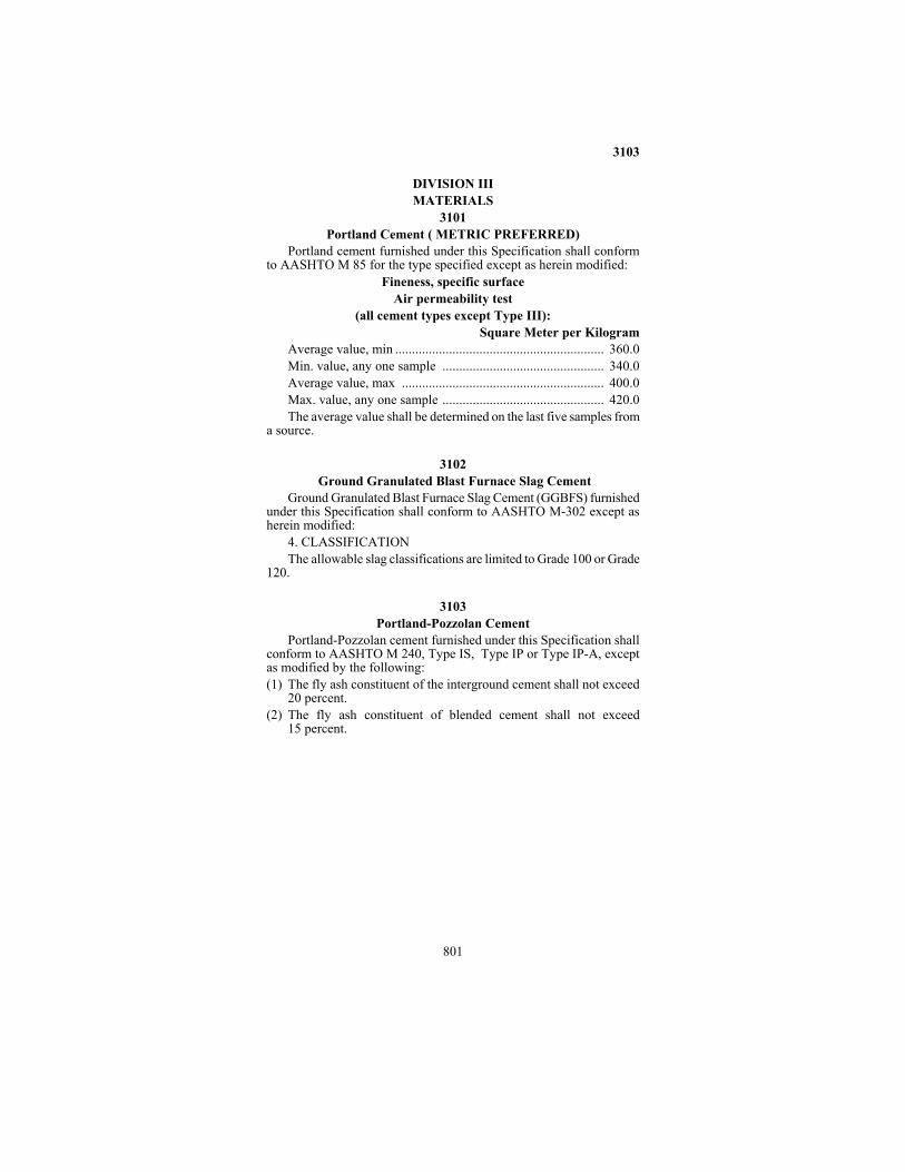
DIVISION III MATERIALS 3101 Portland Cement ( METRIC PREFERRED)
Portland cement furnished under this Specification shall conform to AASHTO M 85 for the type specified except as herein modified:
Fineness, specific surface Air permeability test
(all cement types except Type III): Square Meter per Kilogram
Average value, min .............................................................. 360.0 Min. value, any one sample ................................................ 340.0 Average value, max ............................................................ 400.0 Max. value, any one sample ................................................ 420.0 The average value shall be determined on the last five samples from
a source.
3102 Ground Granulated Blast Furnace Slag Cement
Ground Granulated Blast Furnace Slag Cement (GGBFS) furnished under this Specification shall conform to AASHTO M-302 except as herein modified:
4. CLASSIFICATION The allowable slag classifications are limited to Grade 100 or Grade
120. 3103 Portland-Pozzolan Cement
Portland-Pozzolan cement furnished under this Specification shall conform to AASHTO M 240, Type IS, Type IP or Type IP-A, except as modified by the following: (1) The fly ash constituent of the interground cement shall not exceed
20 percent. (2) The fly ash constituent of blended cement shall not exceed
15 percent.

3105
802
3105 Bagged Portland Cement Concrete Patching Mix Grade 3U18 3105.1 SCOPE
This Specification provides for a dry, bagged concrete patching mix for repairing Portland cement concrete pavement. 3105.2 REQUIREMENTS A Materials
The materials for the patching mix shall meet the following requirements of the type and grade specified.
Cement .................................................................................. 3101 Fine Aggregate ...................................................................... 3126 Coarse Aggregate .................................................................. 3137 Materials to be used with this patching mix to make concrete shall
meet the following requirements: Water...................................................................................... 3906 Admixtures ............................................................................ 3113
B Gradation The coarse and fine aggregate shall be blended at 50-50 ratio by
volume to meet the following gradation: Sieve Size Percent Passing
9.5 mm (3/8"inch) .................................................................. 100 4.75 mm (#4).......................................................................80-100 2.36 mm (#8)........................................................................ 40-80 1.18 mm (#16) ..................................................................... 25-50 600 µm (#30) ...................................................................... 15-35 300 µm (#50) .........................................................................0-18 150 µm (#100) ........................................................................ 0-8 75 µm (#200) .......................................................... 2.3 Maximum
C Mix Proportions The mix proportions shall be as follows per 35-kg (75 pound) bag of dry mix:
Type I Cement .................................................... 8.3 kg (17.8 lbs) Coarse Aggregate ............................................. 13.2 kg (28.3 lbs) Fine Aggregate ................................................. 13.5 kg (28.9 lbs)
D Blending Prior to blending with the cement, the coarse and fine aggregate
shall be dried in a method approved by the Concrete Engineer.

3107
803
The blending device shall be capable of producing the required mix proportions within a tolerance of 2 percent. The proportioning device shall be equipped with a warning device to indicate when the system is out-of-tolerance. The cement and aggregate shall be blended before the mix is bagged.
The blending device shall have the capability to stop the flow of cement to allow sampling of the blended coarse and fine aggregate.
The equipment shall be designed so that sufficient quantities of cement and aggregate may be run out separately to check their masses (weights) and thus ensure that the blending proportions meet mix requirements. E Bags and Batch Identification
The bags shall be moisture-proof, have sufficient strength to resist tearing and hold 35 kg (75 pounds) of mix.
The bags shall be identified by the following statement printed clearly on the bags:
"Mn/DOT GRADE 3U18 CONCRETE PATCH MIX - 35 kg (75 pounds)” The batch shall be identified by the date mixed, such as 07/13/99.
The instructions for mixing into concrete shall be printed on the bag. 3105.3 SAMPLING AND APPROVAL
All materials shall be sampled prior to blending at the bagging site. This shall be construed to mean the individual materials as well as the aggregate blend. Providing the materials meet requirements, the batch will be designated "approved" and identified by the bagging date. Additional field sampling will not be required.
3106 Hydrated Lime
Hydrated lime furnished for use in soil drying or stabilization shall conform to AASHTO M 216.
Hydrated lime furnished for use in mortar for sewer applications shall conform to ASTM C 207, Type S.
Hydrated lime furnished for use in mortar, other than for sewer applications, or road pavement mixtures shall conform to ASTM C 207 for Type N. 3107 Masonry Cement
Masonry cement furnished for use in mortar for sewer applications shall conform to ASTM C 91, Type S.

3107
804
Masonry cements furnished for use in mortar, other than for sewer applications, shall conform to ASTM C 270 and the type specified by the Engineer. 3113 Admixtures for Concrete 3113.1 SCOPE
This Specification covers materials intended for use as admixtures to be added to concrete mixtures in the field. 3113.2 GENERAL
This Specification covers three classes of admixtures, described as follows: Class I - Accelerating, Retarding, and Water-Reducing admixtures.
Type A - Water-reducing Type B - Retarding Type C - Accelerating Type D - Water-reducing and retarding. Type E - Water-reducing and accelerating. Type F - Water-reducing, high range. Type G - Water-reducing, high range and retarding
Class II - Air-Entraining Admixtures Class III - Calcium Chloride 3113.3 REQUIREMENTS A Materials A1 Class I
Class I admixtures shall conform to AASHTO M 194. In addition, Type F and Type G shall require specific approval for use on the intended Project. This approval will only be granted when the Contractor can adequately demonstrate, to the Concrete Engineer, the ability to properly mix, control and place concretes containing the specific admixture. A2 Class II
Class II admixtures shall conform to AASHTO M 154 except as hereinafter provided. (a) Tests for bleeding, bond strength and volume change will not be
required. (b) The air-entraining admixture as used shall have a strength such that
not more than 2.5 liter (2 quarts) of the solution per cubic meter (yard) of concrete will produce the required air content in the concrete.
3113.4
805
(c) Any air-entraining admixture solution made from Vinsol resin shall have a concentration between 14 and 17 percent solids by mass (weight) at the time it is measured and dispensed into the concrete batch. The use of admixtures containing 14 to 30 percent solids may be permitted when used in conjunction with concrete containing fly ash.
A3 Class III Class III admixtures (calcium chloride) shall conform to
AASHTO M 144. B Acceptance B1 For any Class I or Class II admixture proposed for use, the Contractor shall submit certified test reports, including a print of the infrared spectrum of the material, covering tests made by a laboratory approved by the Engineer. Determination as to compliance with these Specifications may be based on the certified test results submitted. B2 When the Contractor proposes to use an admixture that has been previously approved, he shall submit a certification stating that the admixture is the same as that previously approved. If an admixture offered for use is essentially the same (with only minor differences in concentration) as another previously approved material, a certification will be required stating that the product is essentially the same as the approved admixture and that no other admixture or chemical agent is present. B3 When the Contractor proposes to use a Class II admixture that is manufactured by neutralizing Vinsol resin with caustic soda (sodium hydroxide), he may submit a certification concerning the admixture in the following form which may be accepted by the Engineer in lieu of the certified test reports required above.
"This is to certify that the product (trade name) as manufactured and sold by the (company) is an aqueous solution of Vinsol resin that has been neutralized with sodium hydroxide. The ratio of sodium hydroxide to Vinsol resin is one part of sodium hydroxide to (number) parts of Vinsol resin. The percentage of solids based on the residue dried at 105�C is (number). No other additive or chemical agent is present in this solution." B4 Any admixture may be accepted on the basis of the certified test results or certification submitted, with the provision that the Department reserves the right to perform additional tests on samples of the material furnished for the work, to determine its compliance with this Specification and suitability of the admixture for the use intended. 3113.4 SAMPLING AND TESTING
Samples shall be taken in such numbers and sizes as required by the Engineer.

3113.4
806
Tests may be made upon samples taken from the product proposed to be furnished by the Contractor for use on the Project or upon samples submitted and certified by the manufacturer as representative of the admixture to be supplied. 3115 (METRIC PREFERRED) Fly Ash for Use in Portland Cement Concrete
Fly ash furnished under this Specification for use in Portland cement concrete shall conform to ASTM C 618, Class F or Class C, except as modified by the following: Chemical Requirements Class F Class C CaO, %, max 30.0 ........................................... 40.0 Loss on ignition, %, max 3.0 .............................................. 3.0 Available alkalies as Na2O, %, max 3.0 ............................................. 3.0 Physical Requirements Fineness: Air permeability, mm2/kg, min 650 ............................................. 650 Quantity retained when wet sieved on a 45 µm (#325) sieve, %, max.......................................................... 30.0 Water requirement, % of control, max 100 ........................................... 100 Strength activity index with Portland cement, at 7 days, % of control, min 75.0........................................... 75.0 Specific gravity, variation from established value, max ± 0.12 .......................................± 0.12
NOTE: The established value for specific gravity is that value which
is stated in the source approval given by the Materials Engineer.
Fly ash produced at plants where the limestone injection process is
used for controlling air pollutants will be considered unacceptable for use in Portland cement concrete.
All delivery invoices shall show the Class of the fly ash and the source (power plant) from which the fly ash is obtained. The change of

3126.2
807
source or color, or both, of fly ash on a Project shall not be permitted without the written approval of the Concrete Engineer and the Engineer.
Fly ash which meets the requirements of both Class C and Class F shall be considered as being Class C Fly Ash. 3126 Fine Aggregate for Portland Cement Concrete 3126.1 SCOPE
This Specification covers fine aggregate for use in Portland cement concrete. 3126.2 REQUIREMENTS A Composition
The fine aggregate shall be a natural sand consisting of particles of sound, durable rock, except that when fine and coarse aggregates are produced simultaneously and by the same operations from natural gravel deposits, the fine aggregate may contain particles of crushed rock of such nature and quantity as are incidentally produced by the normal operations of crushing and screening the oversize material of the deposit. B Washing
The fine aggregate shall be washed. C Deleterious Substances
The quantity of deleterious substances, as determined by mass (weight), shall not exceed the following limits: C1 Coal and Lignite ...........................................................0.3% C2 BLANK C3 Other deleterious substances such as shale,
alkali, mica, soft and flaky particles, cumulative total ...........................................................2.5%
D Organic Impurities The fine aggregate shall be free of injurious quantities of organic
impurities. Aggregates subjected to the colorimetric test for organic impurities and producing a color darker than the standard shall be rejected unless they pass the mortar strength requirements specified in 3126.2E. E Structural Strength
When subjected to the structural strength tests, mortar specimens containing the fine aggregate shall develop a compressive strength at the age of 3 days when using high early strength Portland cement, or at 7 days when using standard Portland cement, of not less than 90 percent of the strength developed by a mortar prepared in the same manner with

3126.2
808
the same cement and graded Ottawa sand having a fineness modulus of 2.40 with a tolerance of 0.10. F Gradation Requirements
Fine aggregate shall be well graded from coarse to fine; and when tested by means of laboratory sieves, shall conform to the following requirements:
Sieve Size Percent Passing 9.50 mm (3/3 inch) .................................................................. 100 4.75 mm (#4) .................................................................... 95-100 2.36 mm (# 8) (A) ............................................................. 80-100 1.18 mm (# 16)......................................................................55-85 600 µm (# 30) .......................................................................30-60 300 µm (# 50) (B) .................................................................. 5-30 150 µm (# 100) ..................................................................... 0-10 75 µm (#200) .......................................................................0-2.5
(A) If the fine aggregate is used with a coarse aggregate that
meets the requirements for coarse aggregate designation CA-15, the quantity passing the 2.36-mm (# 8) sieve may be decreased to 75 percent.
(B) Fine aggregate of which less than 5 percent passes a 300 µm (# 50) sieve may be used provided an approved inorganic material is added, by separate measurement, to correct the deficiency in gradation.
G Requirements for Uniformity of Grading The gradation requirements specified above represent the extreme
limits that will determine acceptability for use of fine aggregate from all sources of supply. However, the gradation from any one source shall be reasonably uniform and free from wide variation within the gradation limits.
For the purpose of controlling the uniformity of the materials from each individual source, an initial Fineness Modulus will be determined when the work begins. Thereafter, additional determinations will be made as additional material is delivered to the work and any material that shows a deviation from the initially determined Fineness Modulus of more than 0.20 tolerance shall be rejected or, at the discretion of the Engineer, it may be used subject to such adjustments in the mix composition as the Engineer deems necessary to compensate for the variation in gradation.
The Fineness Modulus of fine aggregate is determined by subtracting the total of the cumulative percentages, by mass, passing the
3127.1
809
following standard sieves having square openings, from 7 and dividing by 100. Standard sieves are 9.50 mm (3/8 inch), 4.75 mm (#4), 2.36 mm (#8), 1.18 mm (#16), 600 µm (#30), 300 µm (#50), and 150 µm (# 100). 3126.3 SAMPLING AND TESTING
Sufficient material must be produced and stockpiled prior to starting concrete production to permit proper sampling and testing of the material before it is used. If material is produced from a previously undeveloped source, the following minimum quantities shall be available for sampling and testing prior to the beginning of construction operations:
For concrete pavement construction ....... 900 metric (1000 tons) For all other types of concrete construction .......................At least
one half of the total quantity required for the work or 180 metric tons (200 tons), whichever is the smaller.
When questionable aggregate is encountered, the aggregate shall be separated when produced into distinct units of not more than 90 metric tons (100 tons) nor less than 25 metric tons (28 tons) or the total required (whichever is less). These units shall be kept separate for a sufficient time to permit proper sampling and testing.
Sampling and testing of fine aggregate will be done in accordance with the following: A Sampling, Sieve Analysis, Deleterious Substances,
Quantity of Material Passing the 75-µm (#200) Sieve ...............Mn/DOT Concrete Manual
B Coal and Lignite .....................................AASHTO T 113 C Organic Impurities .................................. AASHTO T 21 D Structural Strength.............................. AASHTO T 71-60 E Specific Gravity and Absorption
The specific gravity and absorption tests will be made in accordance with the procedures on file at the Materials Laboratory. 3127 Fine Aggregate for Bituminous Seal Coat 3127.1 SCOPE
This Specification covers fine aggregate for use in bituminous seal coat.
3127.2
810
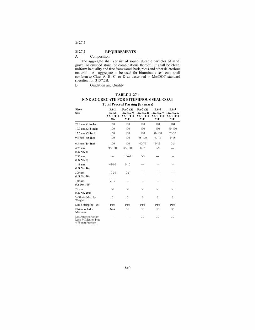
3127.2 REQUIREMENTS A Composition
The aggregate shall consist of sound, durable particles of sand, gravel or crushed stone, or combinations thereof. It shall be clean, uniform in quality and free from wood, bark, roots and other deleterious material. All aggregate to be used for bituminous seal coat shall conform to Class A, B, C, or D as described in Mn/DOT standard specification 3137.2B. B Gradation and Quality TABLE 3127-1 FINE AGGREGATE FOR BITUMINOUS SEAL COAT Total Percent Passing (by mass) Sieve Size
FA-1 Sand
AASHTO M6
FA-2 (A) Size No. 9 AASHTO
M43
FA-3 (A) Size No. 8 AASHTO
M43
FA-4
Size No. 7 AASHTO
M43
FA-5
Size No. 6 AASHTO
M43 25.0 mm (1 inch)
100
100
100
100
100
19.0 mm (3/4 inch)
100
100
100
100
90-100
12.5 mm (½ inch)
100
100
100
90-100
20-55
9.5 mm (3/8 inch)
100
100
85-100
40-70
0-15
6.3 mm (1/4 inch)
100
100
40-70
0-15
0-5
4.75 mm (US No. 4)
95-100
85-100
0-15
0-5
---
2.36 mm (US No. 8)
--
10-40
0-5
---
--
1.18 mm (US No. 16)
45-80
0-10
---
--
--
300 µm (US No. 50)
10-30
0-5
--
--
--
150 µm (Us No. 100)
2-10
--
--
--
--
75 µm (US No. 200)
0-1
0-1
0-1
0-1
0-1
% Shale, Max, by Weight
5
5
3
2
2
Static Stripping Text
Pass
Pass
Pass
Pass
Pass
Flakiness Index, Maximum
N/A
30
30
30
30
Los Angeles Rattler Loss, % Max on Plus 4.75-mm Fraction
--
--
30
30
30

3127.2
811
(A) Except as otherwise specified in the Plans or in the detailed Specifications for a specific type of work, only Classes A, C, or D (as described in 3137.2B) will be permitted.
3127.3 SAMPLING AND TESTING A Sampling, Sieve Analysis, and
Shale Test ..........................Mn/DOT Bituminous Manual B Static Stripping Test..................................AASHTO T 96 C Flakiness Index ................................................ FLH T 508 D Los Angeles Rattler Loss ......................... AASHTO T 96 3128 Mortar Sand
Mortar sand shall conform to AASHTO M 45 and shall be uniformly graded from fine to coarse with the following limits: Percent Passing 2.36-mm (#8).................................................................... 100 Passing 300-µm (# 50) ............................................................... 15-40 Passing 150-µm (# 100) ................................................................0-10 Passing 75-µm (# 200) ................................................................... 0-5 3137 Coarse Aggregate for Portland Cement Concrete 3137.1 SCOPE
This Specification covers coarse aggregate for use in Portland cement concrete. 3137.2 REQUIREMENTS A General
For sources that have not been previously tested, or for sources of questionable quality, the aggregate may be used only if specifically approved by the Engineer and then only after it has been evaluated and determined to be satisfactory for the proposed use.
The Engineer shall be notified at least 4 weeks prior to use of the proposed aggregate, to permit special studies as necessary to determine its suitability. To determine suitability of any aggregate, the Engineer may consider the results of laboratory tests, the behavior of the rock under natural exposure conditions, the behavior of Portland cement concrete in which aggregate from the same or similar geological formations or deposits has been used, or such other tests or criteria as he may deem appropriate.
3127.2
812
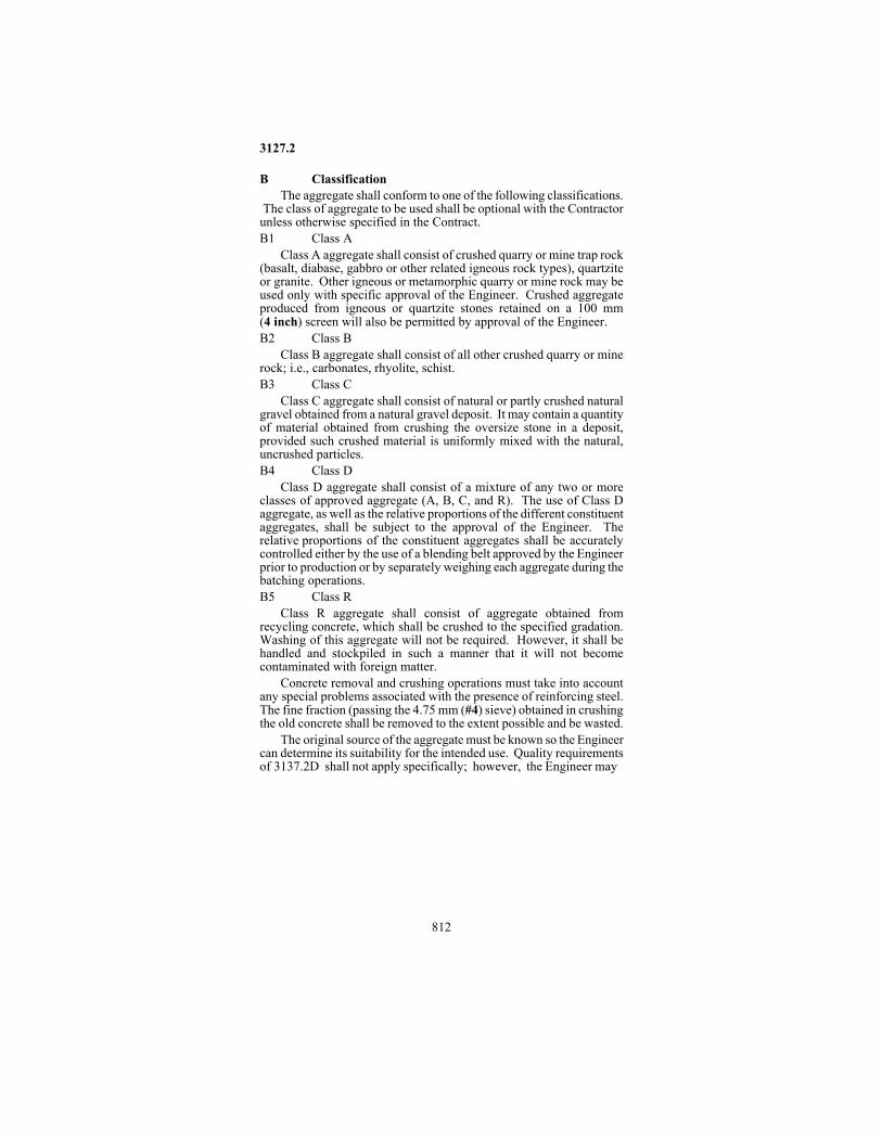
B Classification The aggregate shall conform to one of the following classifications.
The class of aggregate to be used shall be optional with the Contractor unless otherwise specified in the Contract. B1 Class A
Class A aggregate shall consist of crushed quarry or mine trap rock (basalt, diabase, gabbro or other related igneous rock types), quartzite or granite. Other igneous or metamorphic quarry or mine rock may be used only with specific approval of the Engineer. Crushed aggregate produced from igneous or quartzite stones retained on a 100 mm (4 inch) screen will also be permitted by approval of the Engineer. B2 Class B
Class B aggregate shall consist of all other crushed quarry or mine rock; i.e., carbonates, rhyolite, schist. B3 Class C
Class C aggregate shall consist of natural or partly crushed natural gravel obtained from a natural gravel deposit. It may contain a quantity of material obtained from crushing the oversize stone in a deposit, provided such crushed material is uniformly mixed with the natural, uncrushed particles. B4 Class D
Class D aggregate shall consist of a mixture of any two or more classes of approved aggregate (A, B, C, and R). The use of Class D aggregate, as well as the relative proportions of the different constituent aggregates, shall be subject to the approval of the Engineer. The relative proportions of the constituent aggregates shall be accurately controlled either by the use of a blending belt approved by the Engineer prior to production or by separately weighing each aggregate during the batching operations. B5 Class R
Class R aggregate shall consist of aggregate obtained from recycling concrete, which shall be crushed to the specified gradation. Washing of this aggregate will not be required. However, it shall be handled and stockpiled in such a manner that it will not become contaminated with foreign matter.
Concrete removal and crushing operations must take into account any special problems associated with the presence of reinforcing steel. The fine fraction (passing the 4.75 mm (#4) sieve) obtained in crushing the old concrete shall be removed to the extent possible and be wasted.
The original source of the aggregate must be known so the Engineer can determine its suitability for the intended use. Quality requirements of 3137.2D shall not apply specifically; however, the Engineer may

3127.2
813
consider any of those requirements in determining suitability of the aggregate. C Washing
All coarse aggregate except for Class A aggregate shall be washed. All coarse aggregate shall meet the 75-µm (# 200) sieve requirements of 3137.2D1. D Quality Requirements D1 Aggregate for General Use
The following percentages, shall not be exceeded: Percent By Mass (Weight)
(a) Shale, In the fraction retained on the 12.5-mm (½') sieve ................. 0.4 Retained on the 4.75-mm (# 4) sieve as a percentage of the total material ..................................................................... 0.7
(b) Soft Iron Oxide Particles (paint rock and ochre) ..................... 0.3 (c) Total Spall Materials (includes items a and b
percentages of the above, plus other iron oxide particles, unsound cherts, pyrite, and other materials having similar characteristics). In fraction retained on the 12.5-mm (½ inch) sieve ................ 1.0 Retained on the 4.75-mm (# 4) sieve, as a percentage of the total material ..................................................................... 1.5
(d) Soft Particles (exclusive of items a, b, and c above) ..................................................................................... 2.5
(e) Clay Balls and Lumps .............................................................. 0.3 (f) Sum of Materials listed under items c, d, and e
above ....................................................................................... 3.5 (For item c use percent in total sample retained on the 4.75-mm (# 4) sieve)
(g) Slate ........................................................................................ 3.0 (h) Thin or Elongated Pieces (maximum thickness less than
25 percent of the maximum width, or maximum length more than 3 times the maximum width) .................................... 15
(i) Material Passing 75-µm (# 200) sieve, on individual fractions .. 1.0 (j) Los Angeles Rattler Loss,
On total sample ......................................................................... 40 (k) Freezing and Thawing, loss at 16 cycles .................................... 12
3137.2
814
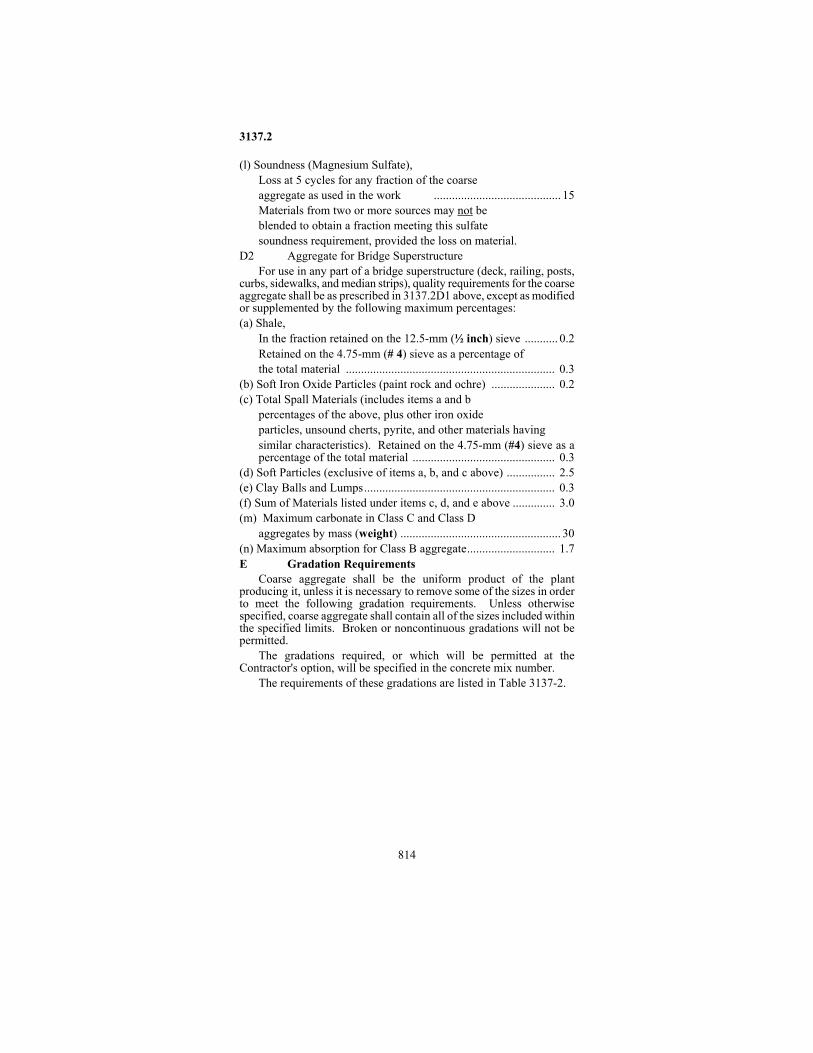
(l) Soundness (Magnesium Sulfate), Loss at 5 cycles for any fraction of the coarse aggregate as used in the work .......................................... 15 Materials from two or more sources may not be blended to obtain a fraction meeting this sulfate soundness requirement, provided the loss on material.
D2 Aggregate for Bridge Superstructure For use in any part of a bridge superstructure (deck, railing, posts,
curbs, sidewalks, and median strips), quality requirements for the coarse aggregate shall be as prescribed in 3137.2D1 above, except as modified or supplemented by the following maximum percentages: (a) Shale,
In the fraction retained on the 12.5-mm (½ inch) sieve ........... 0.2 Retained on the 4.75-mm (# 4) sieve as a percentage of the total material ..................................................................... 0.3
(b) Soft Iron Oxide Particles (paint rock and ochre) ..................... 0.2 (c) Total Spall Materials (includes items a and b
percentages of the above, plus other iron oxide particles, unsound cherts, pyrite, and other materials having similar characteristics). Retained on the 4.75-mm (#4) sieve as a percentage of the total material ............................................... 0.3
(d) Soft Particles (exclusive of items a, b, and c above) ................ 2.5 (e) Clay Balls and Lumps............................................................... 0.3 (f) Sum of Materials listed under items c, d, and e above .............. 3.0 (m) Maximum carbonate in Class C and Class D
aggregates by mass (weight) ..................................................... 30 (n) Maximum absorption for Class B aggregate............................. 1.7 E Gradation Requirements
Coarse aggregate shall be the uniform product of the plant producing it, unless it is necessary to remove some of the sizes in order to meet the following gradation requirements. Unless otherwise specified, coarse aggregate shall contain all of the sizes included within the specified limits. Broken or noncontinuous gradations will not be permitted.
The gradations required, or which will be permitted at the Contractor's option, will be specified in the concrete mix number.
The requirements of these gradations are listed in Table 3137-2.
3137.3
815
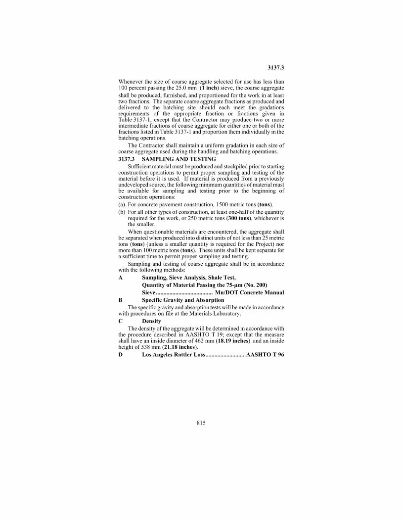
Whenever the size of coarse aggregate selected for use has less than 100 percent passing the 25.0 mm (1 inch) sieve, the coarse aggregate shall be produced, furnished, and proportioned for the work in at least two fractions. The separate coarse aggregate fractions as produced and delivered to the batching site should each meet the gradations requirements of the appropriate fraction or fractions given in Table 3137-1, except that the Contractor may produce two or more intermediate fractions of coarse aggregate for either one or both of the fractions listed in Table 3137-1 and proportion them individually in the batching operations.
The Contractor shall maintain a uniform gradation in each size of coarse aggregate used during the handling and batching operations. 3137.3 SAMPLING AND TESTING
Sufficient material must be produced and stockpiled prior to starting construction operations to permit proper sampling and testing of the material before it is used. If material is produced from a previously undeveloped source, the following minimum quantities of material must be available for sampling and testing prior to the beginning of construction operations: (a) For concrete pavement construction, 1500 metric tons (tons). (b) For all other types of construction, at least one-half of the quantity
required for the work, or 250 metric tons (300 tons), whichever is the smaller. When questionable materials are encountered, the aggregate shall
be separated when produced into distinct units of not less than 25 metric tons (tons) (unless a smaller quantity is required for the Project) nor more than 100 metric tons (tons). These units shall be kept separate for a sufficient time to permit proper sampling and testing.
Sampling and testing of coarse aggregate shall be in accordance with the following methods: A Sampling, Sieve Analysis, Shale Test,
Quantity of Material Passing the 75-µm (No. 200) Sieve ...................................... Mn/DOT Concrete Manual
B Specific Gravity and Absorption The specific gravity and absorption tests will be made in accordance
with procedures on file at the Materials Laboratory. C Density
The density of the aggregate will be determined in accordance with the procedure described in AASHTO T 19; except that the measure shall have an inside diameter of 462 mm (18.19 inches) and an inside height of 538 mm (21.18 inches). D Los Angeles Rattler Loss...........................AASHTO T 96

3137.3
816
E Void Content The procedure for determining voids in the aggregate shall be as
outlined in AASHTO T 19, except that the void content shall be based on an oven-dry and compacted (by rodding) condition of the aggregate, and a value of 1000 kg/m3 (62.3 pounds per cubic foot) for water. F Deleterious Materials
The percentages, by mass (weight), of such materials as coal, lignite, iron oxide particles, slate and similar deleterious substances will be determined by visual analysis of the sample. G Freezing and Thawing
The aggregate will be tested for resistance to freezing and thawing in water and alcohol, and for strain and freeze-thawing, in accordance with the procedures on file at the Materials Laboratory. H Soundness (Magnesium Sulfate)
The sulfate soundness of the aggregate will be determined by using the procedure described in AASHTO T 104, except as modified in the test procedure on file at the Materials Laboratory. I Blank J Soft Particles
The percentage of soft particles will be determined by the Method of Test for Scratch Hardness of Coarse Aggregate, on file at the Materials Laboratory.
3137.3
817
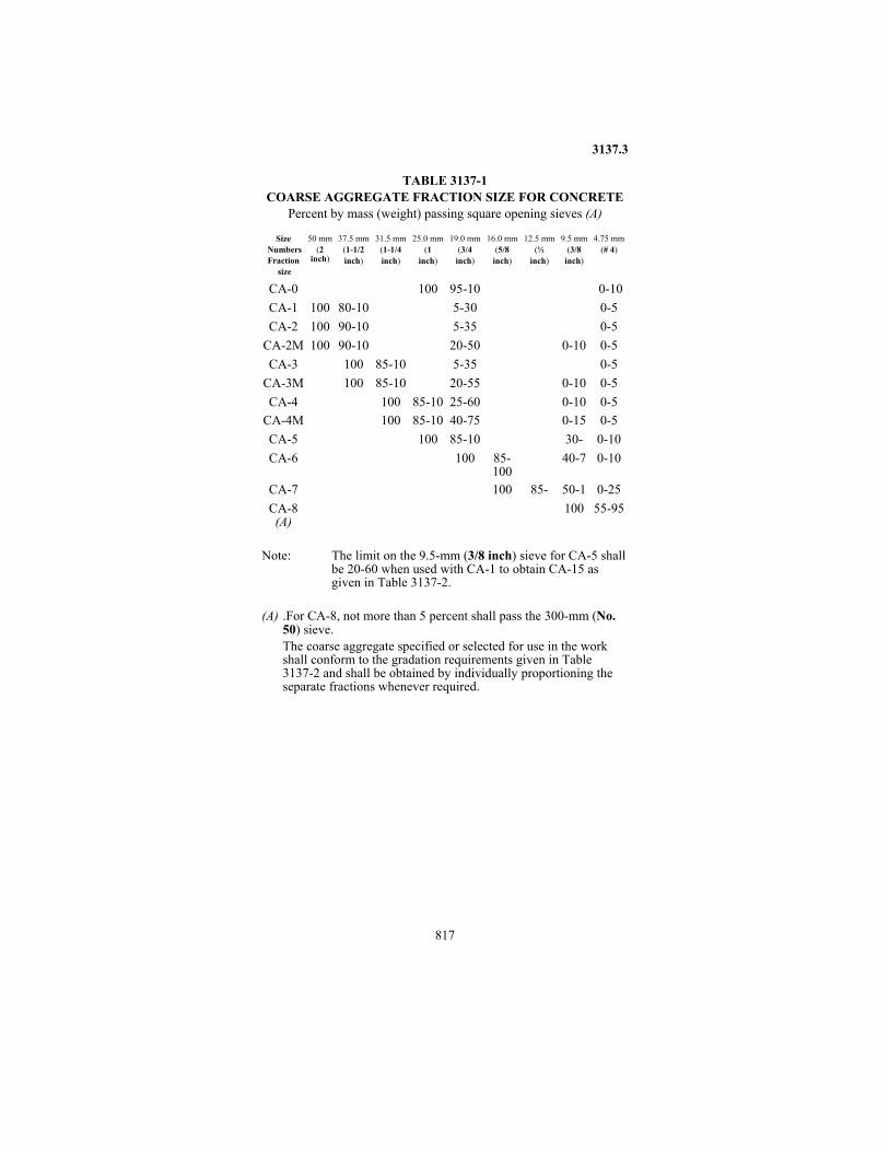
TABLE 3137-1 COARSE AGGREGATE FRACTION SIZE FOR CONCRETE
Percent by mass (weight) passing square opening sieves (A)
Size Numbers Fraction
size
50 mm
(2 inch)
37.5 mm
(1-1/2 inch)
31.5 mm
(1-1/4 inch)
25.0 mm
(1 inch)
19.0 mm
(3/4 inch)
16.0 mm
(5/8 inch)
12.5 mm
(½ inch)
9.5 mm
(3/8 inch)
4.75 mm
(# 4)
CA-0
100
95-10
0-10
CA-1 100
80-10
5-30
0-5
CA-2 100
90-10
5-35
0-5
CA-2M 100
90-10
20-50
0-10
0-5
CA-3
100 85-10
5-35
0-5
CA-3M
100 85-10
20-55
0-10
0-5
CA-4
100 85-10
25-60
0-10
0-5
CA-4M
100 85-10
40-75
0-15
0-5
CA-5
100 85-10
30-
0-10
CA-6
100
85-100
40-7
0-10
CA-7
100
85-
50-1
0-25
CA-8 (A)
100
55-95
Note: The limit on the 9.5-mm (3/8 inch) sieve for CA-5 shall
be 20-60 when used with CA-1 to obtain CA-15 as given in Table 3137-2.
(A) .For CA-8, not more than 5 percent shall pass the 300-mm (No. 50) sieve. The coarse aggregate specified or selected for use in the work shall conform to the gradation requirements given in Table 3137-2 and shall be obtained by individually proportioning the separate fractions whenever required.
3137.3
818
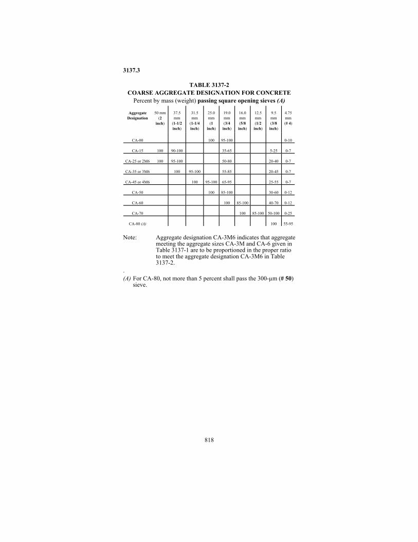
TABLE 3137-2 COARSE AGGREGATE DESIGNATION FOR CONCRETE Percent by mass (weight) passing square opening sieves (A)
Aggregate Designation
50 mm
(2 inch)
37.5 mm
(1-1/2 inch)
31.5 mm
(1-1/4 inch)
25.0 mm (1
inch)
19.0 mm (3/4
inch)
16.0 mm (5/8
inch)
12.5 mm (1/2
inch)
9.5 mm (3/8
inch)
4.75 mm (# 4)
CA-00
100
95-100
0-10
CA-15
100
90-100
35-65
5-25
0-7
CA-25 or 2M6
100
95-100
50-80
20-40
0-7
CA-35 or 3M6
100
95-100
55-85
20-45
0-7
CA-45 or 4M6
100
95-100
65-95
25-55
0-7
CA-50
100
85-100
30-60
0-12
CA-60
100
85-100
40-70
0-12
CA-70
100
85-100
50-100
0-25
CA-80 (A)
100
55-95
Note: Aggregate designation CA-3M6 indicates that aggregate
meeting the aggregate sizes CA-3M and CA-6 given in Table 3137-1 are to be proportioned in the proper ratio to meet the aggregate designation CA-3M6 in Table 3137-2.
. (A) For CA-80, not more than 5 percent shall pass the 300-µm (# 50)
sieve.

819
THIS PAGE HAS
BEEN INTENTIONALLY
LEFT BLANK.

3138
820
3138 Aggregate for Surface and Base Courses 3138.1 SCOPE
This Specification covers the quality of aggregates used in construction of aggregate surfaced roads, shoulders and dense graded base courses. 3138.2 REQUIREMENTS A. Aggregate Composition
The source of supply and quality of the material is subject to approval by the Engineer in accordance with 1601. A1. Virgin Aggregate Composition
Classes 1, 2, 3, 4, 5 and 6 shall meet the following requirements: All aggregate sources (pits and quarries) from which surface and/or
base course aggregates are produced shall be stripped to uncover suitable materials for use. In quarries, all weathered rock will be removed prior to production of the face.
The mixture shall consist of 100 percent virgin aggregates (unless noted otherwise), and shall consist of sound durable particles or fragments of gravel and sand, crushed quarry or mine rock, crushed gravel or stone or any combination thereof; except that, Class 2 aggregates shall consist of 100 percent crushed quarry or mine rock.
The Engineer may allow aggregates containing a limited quantity of binder soil; however, the aggregates shall not contain sod, roots, plants, other organic matter, or other objectionable material. All materials shall be free from lumps or balls of clay. A2. Salvaged/Recycled Aggregate Mixtures
Class 7 Salvaged/recycled aggregate materials may be used or blended with
a combination of virgin and salvaged/recycled aggregates or 100% salvaged/recycled aggregate materials as permitted in accordance with the following requirements. These composite mixtures/ blends shall be designated as Class 7.
The composite mixture/blend shall meet the following requirements: (a) A salvage/recycled mixture shall have a minimum of 10 percent by
mass (weight) salvage/recycle aggregate material incorporated into the mixture to be considered a salvage/recycled mixture.
(b) Virgin aggregates that are incorporated into the mixture shall meet the requirements in Sections 3138.2A1, 3138.2D, and 3138.2E.
(c) The salvaged/recycled aggregate portion of the mixture shall consist of sound durable particles produced by crushing, screening and grading to the required sizes from materials which were

3138.2
821
salvaged from the following sources: Portland cement concrete pavement removal and/or other concrete structural elements, bituminous pavement removal, aggregate bases underlying bituminous and concrete pavements. Incorporation of recycled glass into the aggregate mixture during production will be permitted. The composite mixture may be produced from any combination of these salvaged/recycled aggregate materials (including glass), unless otherwise specifically modified or prohibited in the plans and/or special provisions. (d) The Engineer may allow aggregate containing a limited quantity of
binder soil. However, the composite aggregate mixture/blend shall not contain sod, roots, plants, building rubble, building brick, wood, plaster, reinforcing steel or other similar objectionable or deleterious materials and shall be free of lumps or balls of clay.
(e) The requirements of 3138 A2(a), Salvaged Bituminous Aggregate Mixtures; 3138 A2(b), Salvaged Crushed Concrete Aggregate; and 3138 A2(c), Reclaimed Glass.
(f) Blending of the various types of aggregates (virgin and recycle/salvage aggregates), shall be done during production. The final product shall consist of a uniform blend of all the composite materials. Class 7 may be substituted for Classes 1, 3, 4, 5 and 6 unless
otherwise specifically modified or prohibited in the plans and/or Special Provisions. A2(a). Salvaged Bituminous Aggregate Mixtures
Salvaged bituminous aggregate mixtures may be used in accordance with the following applications and requirements: (a) Aggregate base course.
Salvaged bituminous mixture may be used either alone or in combination with other aggregate materials (virgin and/or salvaged/recycled) in the production of the base course mixture. However, the bitumen content of the composite mixture shall not exceed three percent by mass (by weight).
(b) Surfacing aggregate (travel lanes and/or shoulders). Up to 100 percent salvaged bituminous mixture may be used. (No limit on bitumen content)
A2(b). Salvaged Crushed Concrete Aggregate Crushed concrete aggregate may be used singularly or blended with
virgin and/or other permitted salvaged/recycled aggregate materials in accordance with the following applications and requirements: (1) Aggregate base course applications.
(a) Where drainage layers and/or perforated drainage pipes are not installed or will not be installed:

3138.2
822
i. Crushed concrete may be used in the production of aggregate base course mixtures provided that the final product meets all other requirements of this specification.
(b) Where drainage layers and/or perforated drainage pipes are installed or will be installed. i. Crushed concrete, blended with other permitted
aggregates (virgin and/or recycled), may be used on any type of subgrade soil provided that at least 95% of the crushed concrete aggregate particles are retained on the 4.75 mm (#4) sieve.
ii. Crushed concrete aggregates may be used singularly or blended with other permitted aggregate materials when placed over material meeting the requirements of 3149.2B2, Select Granular, provided that the amount crushed concrete aggregate does not exceed the equivalent of 75 mm (3 inches) of 100 percent crushed concrete; such as, 150 mm (6 inches) of a 50/50 blend of crushed concrete and permitted aggregate material. If crushed concrete aggregate is used (singularly or blended) for the base course and for stabilizing the subgrade at the same location, the total equivalent application rate shall not exceed a 75 mm (3 inch) thickness (approximately 160 kg per square meter (300 pounds per square yard) of surface area)).
iii. Crushed concrete may be used up to 100% in construction of the filter/separation layer under a permeable aggregate base drainage layer (i.e. OGAB, PASB, PCSB) in accordance with the applicable drainage specifications.
(2) Other Applications. With and without drainage layer and/or perforated pipe installation, crushed concrete may be used for:
i. Surfacing and base course(s) in the shoulder area. ii Surfacing aggregate-surfaced roads (including
shoulders). A2(c) Reclaimed Glass
Unless otherwise specifically modified or prohibited in the Plans and/or Special Provisions, up to 10 percent by mass (weight) reclaimed glass may be mixed/blended with virgin and/or salvaged/recycled aggregate materials during the crushing operation in the production of the aggregate base course mixture in accordance with the following:

3138.2
823
1. Sources Reclaimed glass shall consist of eligible secondary glass available from any source willing and able to certify their supply sources and composition of glass as required in paragraph 7, below.
2. Composition Reclaimed glass shall consist only of the following eligible types of glass products: a. container glass used for consumer food and beverages; b. beverage drinking glasses; c. plain ceramic or china dinerware; d. building window glass free of any framing material; and e. other types of glass that can be certified and approved by Mn/DOT’s Office of Environmental Services on an individual source basis.
Reclaimed glass or other salvaged aggregates shall not consist of the following prohibited types of materials: a. any hazardous waste as defined in MPCA Rules 7045; b. hazardous substance in regulated quantities listed in 40 CFR, Table 302.4; c. automobile windshields or other glass from automobiles; d. light bulbs of any type; e. porcelain products; f. laboratory glass; and g. television, computer or other cathode ray monitor tubes.
3. Debris Content The reclaimed glass shall not contain more than 5 percent debris, by visual inspection. Debris includes any non-glass material such as: paper, foil, plastics, metal, corks, wood debris, food residue, or other deleterious materials. The percentage of debris shall be estimated using the American Geophysical Institute Visual Method. (AGI Data Sheet 15.1 and 15.2 Comparison Chart for Estimating Percent Composition, 1982.)
4. Storage Interim storage of reclaimed glass stockpiles shall be on locations with: a. minimum of 1.2 meters (four feet) depth of suitable soils separating groundwater; b. a minimum of 50 meters (150 feet) away from any surface water body; and c. a maximum slope for four percent (4%) if sloped to any surface water body.
5. Ratio of Reclaimed Glass Up to 10 percent by mass (weight) reclaimed glass may be mixed virgin and/or other salvaged/recycled aggregate materials during the crushing operation in the production of the aggregate mixture.

3138.2
824
6. Applications Reclaimed glass blended with other aggregates may be used for aggregate base course mixtures. Reclaimed glass shall not used in aggregate surfacing applications including shoulder surfacing.
7. Certification a. The contractor shall provide documentation certifying
that the reclaimed glass: (i) is only from sources that have given the contractor the certification required in paragraph b) below, sub-item (ii), is comprised of only eligible types of reclaimed glass; (iii) does not contain any prohibited materials; (iv) meets debris content requirements; (v) meets the blending ratio requirements; and (vi) is or will be stored according to storage requirements described in paragraph 4 above.
b. Documentation shall include, at a minimum: (i) written certification from sources of reclaimed glass, such as recycling centers, that a good faith effort of public education was used to inform resident and business of the eligible and prohibited types of glass to be included for recycling, (ii) written certification by recycling centers that their independent sources of reclaimed glass, such as private recyclables haulers, have been notified in writing of these composition and public education requirements and have agreed in writing to comply with them; and (iii) description of the reclaimed glass blending methods used to assure required blending ratios.
A3 Limestone and/or Dolostone The following provisions shall apply in these listed counties:
Anoka - 02 Ramsey - 62 Carver - 10 Scott - 70 Dakota - 19 Washington - 82 Hennepin - 27
All counties in Mn/DOT’s Districts 6 (a) If crushed carbonate (limestone or dolostone) quarry/bedrock is
used in total or in part for base applications, unless exempted below, the portion passing the 75 µm (#200) sieve of the carbonate aggregate insoluble residue shall not exceed 10 percent.

3138.2
825
(b) An exemption to this 10 percent insoluble residue Specification will be made for carbonate rock to be used as temporary by-passes and parking lots. Use on other specific non-exempted applications must be approved by the Engineer. For these exempted applications, the portion passing the 75 µm (# 200) sieve of the carbonate aggregate insoluble residue test shall not exceed 16 percent.
B. Gradation........................................................... TABLE 3138-1 In the event that it is necessary to add a portion of the overburden
or binder soil from an outside source, the materials shall be introduced into the aggregate producing plant at a uniform rate by a separate conveyor simultaneously with the base aggregate. The binder soils or overburden shall meet 3146.
Class 7 aggregate mixtures shall meet the gradation requirements shown in Table 3138-1; except that, when salvaged/recycled bituminous mixture is incorporated into the production of the aggregate base mixture, up to 5 percent by mass (weight) of the total composite mixture may exceed 25.0 mm, (1 inch) provided that these larger particles are bituminous mixture and not other aggregate types, and are not larger than 37.5 mm (1.5 inch). (All gradations will be run on the composite mixture before extraction of the bituminous material.)
If reclaimed glass is incorporated into the aggregate base material, the final product shall conform to the requirements of Class 7.
In the production of Class 7 aggregate materials, the different aggregate types shall be blended at uniform proportions/rates.
At the time of testing Class 7 ( ) shall be further identified as to the type of recycle/salvage aggregate materials that are incorporated into the final product by the following designations:
B - Bituminous Mixture .........................................................7(B) C - Concrete ...........................................................................7(C) BC - Bituminous and Concrete ........................................... 7(BC) G - Glass ................................................................................7(G) BG ....................................................................................... 7(BG) CG........................................................................................7(CG) BCG ................................................................................. 7(BCG) M - Misc. - must be specified in Special Provisions
C Crushing Crushing will be required for Class 5 and 6 aggregates. For these
classes of aggregate, crushing will be required of all stones larger than the maximum size permitted by the gradation requirements and that will pass a grizzly or bar grate having parallel bars spaced 200 mm (8 inch) apart. However, the Engineer may allow rejection of oversize material when excessive crushing results in an unsatisfactory gradation.

3138.2
826
Class 6 aggregates shall contain at least 15 percent crushed material. Class 5 aggregates shall contain at least 10 percent crushed material. The percentage of crushing shall be determined by the procedures described in the Grading and Base Manual. A tolerance of 2 percent will be allowed on each individual test, but the average of all material tested for the project shall meet the specification requirements. It may be necessary to add stones or crushed rock from another source to meet the crushing requirements. D Los Angeles Rattler Loss
The Los Angeles Rattler Loss requirements shall apply only to the crushed quarry or mine rock portion of the aggregate.
Class of Aggregates Los Angeles Rattler Loss 1, 2, 3, 4, 5, 7 ........................................................ 40% maximum 6, ...........................................................................35% maximum The LAR maximum loss shown for Class 7 shall be determined on
the virgin aggregate portion of the mixture prior to the incorporation of the salvage/recycle materials into the final composite mixture. E Shale
Class 3, 4, and 5 aggregate shall contain not more than 10 percent shale in the total sample; except that, when the part passing a 75-µm (# 200) sieve exceeds 7 percent, the percentage of shale in the total sample shall not exceed 7 percent.
Class 6 aggregate shall contain not more than 7 percent shale in the total sample.
The virgin aggregate portion of the Class 7 mixture shall not contain more shale than allowed for the Class of aggregate that the substitution is being made. Testing for compliance shall be performed prior to the incorporation of the salvage/recycled materials into the final composite mixture. 3138.3 SAMPLING AND TESTING
Samples for testing to determine compliance with the aggregate gradation specifications for base and shoulder surfacing will be obtained from the roadway at a time when the material is ready for compaction. The samples may be obtained from the windrow or after blending and spreading of the material on the roadway. However, Classes 1, 2 and 7 shoulder surfacing aggregates may be sampled from a stockpile, tested, and accepted before roadway placement, provided that:
(a) No more than 25 percent of the stockpile samples fail to meet gradation requirements.
(b) The average of all stockpile tests meet requirements.

3138.3
827
(c) The contractor mixes the material during placement to the satisfaction of the Engineer.
The stockpile shall be sampled at the rate of one field gradation test per 1000 metric tons (ton) of aggregate used on the project.
If additives such as calcium chloride or bituminous material are incorporated in a central mixing plant, the aggregate will be sampled before such materials are added.
A Sampling, Sieve Analysis, Shale, and Crushing Test ....... ........................ Mn/DOT Grading and Base Manual
B Los Angeles Rattler Loss ......................... AASHTO T 96 C Sampling and Shale Tests ..................................................
......................................... Mn/DOT Laboratory Manual D Bitumen Content: ............Mn/DOT Laboratory Manual
a) By Extraction........................ Methods 1851 or 1852 or b) Incineration Oven ................................ Methods 1853
E Insoluble Residue............. Mn/DOT Laboratory Manual ........................................................................Method 1221
F Reclaimed Glass ........... American Geophysical Institute Visual Method (AGI Data sheet 15.1 and 15.2, Comparison chart for Estimating Percent Composition 1982)

3138.3
828
TABLE 3138-1 BASE AND SURFACING AGGREGATE
Total Percent Passing Sieve
Size
Class
1
Class
2
Class
3
Class
4
Class
5
Class
6
Class 7(a)
(b)(c)
75 mm (3 inches)
--
--
--
--
--
--
--
50 mm
(2 inches)
--
--
100
100
--
--
--
37.5 mm
(1½ inches)
--
--
--
--
--
--
--
25.0 mm (1 inch)
--
--
--
--
100
100
--
19.0 mm
(3/4 inch)
100
100
--
--
90-100
90-100
--
9.5 mm
(3/8 inch)
65-95
65-90
--
--
50-90
50-85
--
40-85
35-70
35-100
35-100
(A) 35-80
35-70
--
4.75 mm (No. 4)
--
--
--
--
(B) 35-70
--
-- 25-70
25-45
20-100
20-100
(A) 20-65
20-55
--
2.00 mm (No. 10)
--
--
--
--
(B) 20-55
--
--
425 µm (No. 40)
10-45
12-30
5-50
5-35
10-35
10-30
--
75 µm
(No. 200)
8-15
5-13
5-10
4-10
3-10
(A) 3-7 (B) 3-8
NOTES:
(A) Applies when the aggregate contains 60 percent or less of crushed quarry rock.
(B) Applies when the aggregate contains more than 60 percent crushed quarry rock. (a) Refer to Section 3138.2B (b) Class 7 shall meet the gradation requirements for
Class 5 when it is being substituted for Classes 1,3,4 and 5.
(c) Class 7 shall meet the gradation requirements for Class 6 when it is being substituted for Class 6.

3139.2
829
3139 Graded Aggregate for Bituminous Mixtures 3139.1 SCOPE
This specification covers graded aggregate for use in bituminous mixtures. 3139.2 REQUIREMENTS A Composition A1 General
The aggregate shall consist of sound, durable particles of gravel and sand, crushed stone and sand, or combinations thereof. It shall be free of matter such as metal, glass, plastic, brick, rubber, and any other objectionable material. Coarse aggregate shall be free from coatings of clay and silt to the satisfaction of the Engineer.
The Contractor shall not compensate for the lack of fines by adding soil materials such as clay, loam, or silt. Overburden shall not be blended into the bituminous aggregate. A2 Classification
The aggregate shall conform to one of the following classifications. The class of aggregate to be used shall be the Contractor’s option unless otherwise specified in the Contract. A2a Class A
Class A aggregate shall consist of crushed igneous bedrock (specifically; basalt gabbro, granite, rhyolite, diorite and andosite) and rock from the Sioux Quartzite formation. Other igneous or metamorphic rock may be used with specific approval of the Engineer. Class A materials may contain no more than 4.0% non=Class A aggregate. This recognizes the fact that some quarries may contain small pockets of non-Class A material within that source. Intentional blending or addition of non-Class A material is strictly prohibited! A2b Class B
Class B aggregate shall consist of crushed rock from all other bedrock sources as carbonate and metamorphic rocks. (gneiss or schist) A2c Class C
Class C aggregate shall consist of natural or partly crushed natural gravel obtained from a natural gravel deposit. A2d Class D
Class D aggregate shall consist of 100 percent crushed natural gravel. The crushed gravel shall be produced from material retained on a square mesh sieve having an opening at least twice as large as the Specification permits for the maximum size of the aggregate in the composite asphalt mixture. The amount of carryover (material finer than) the selected screen shall not exceed ten percent.

3139.2
830
A2e Class E Class E aggregate shall consist of a mixture of any two or more of
the following: Class A, Class B, and/or Class D. The relative proportions of the constituent aggregates shall be accurately controlled either by the use of a blending belt approved by the Engineer prior to production or by separately weighing each aggregate during batching operations. A3 Bituminous Mixture Components
Components for bituminous mixtures produced under 2331, 2340, 2350, and 2360 shall be Class A, Class B, Class C, Class D, Class E, taconite tailings, steel slag, or combination thereof. The use of Class E aggregate, as well as the relative proportions of the different constituent aggregates, shall be subject to the approval of the Engineer. A3a Steel Slag (SS)
Steel slag may be used in quantities not to exceed 25 percent of the mass of the total aggregate. Stockpiles will be accepted for use if the total expansion, determined by ASTM D4792, is less than 0.50%. A3b Taconite Tailings (TT)
Taconite tailings shall be obtained from ore that is mined westerly of a north-south line located east of Biwabik, MN (R15W-R16W); except that taconite tailings from ore mined in southwestern Wisconsin will also be permitted for use.
Approved taconite tailing sources are on file with the Bituminous Engineer. A3c Aggregate for Type 61 Mixtures
For Mixture Type 61 aggregate, the aggregate(s) used for mixture production shall consist of a single type or a combination of primary aggregate types, or a composite blend of primary and secondary aggregates. If any Type 61 mixture aggregate is blended with any other Type 61 mixture aggregate, the Crushed Stone (CS) gradation requirements shall apply. The Type 61 mixture aggregate may have 20 percent or less (by mass) of secondary aggregate.
The primary aggregate shall consist of material meeting the following requirements: (1) Crushed Stone (CS)
- For wearing course: Crushed stone shall conform to Class A, Class D, or a combination thereof.
- For non-wearing course: Crushed Stone shall conform to Class A, Class B, Class D, or a combination thereof.
(2) Taconite Tailings (TT) Taconite tailings shall be obtained from ore that is mined westerly of a north-south line located east of Biwabik, Mn (R15W-R16W);
3139.2
831
except that taconite tailings from ore mined in southwestern Wisconsin will also be permitted for use. Approved taconite tailing sources are on file with the Bituminous Engineer.
(3) Steel Slag (SS) Steel slag may not exceed 25 percent of the mass of the total aggregate. Stock piles will be accepted for use if the total expansion, determined by ASTM D4792 is less than 0.50%. The secondary aggregate shall consist of sound, durable particles of
gravel and sand, crushed quarry/mine rock or screenings, synthetic aggregates, or combinations thereof. Synthetic aggregates, excluding steel slag, must have the approval of the Engineer prior to use.
A composite aggregate blend shall consist of at least 80 percent (by mass) of a primary type aggregate or combination of primary type aggregates. B Gradation
The aggregates for mixtures produced under 2331 and 2340 shall comply with the gradation requirements in Table 3139-1.
3139.2
832
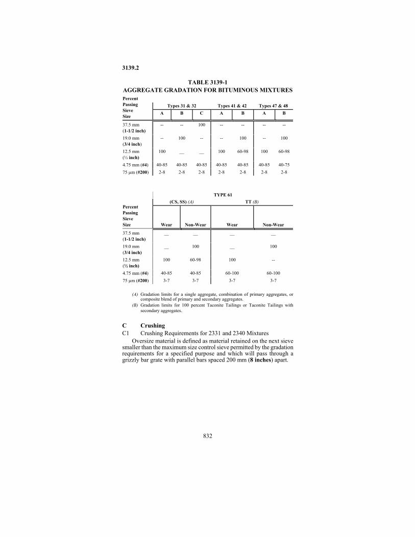
TABLE 3139-1 AGGREGATE GRADATION FOR BITUMINOUS MIXTURES
Types 31 & 32
Types 41 & 42
Types 47 & 48
Percent Passing Sieve Size
A
B
C
A
B
A
B
37.5 mm (1-1/2 inch)
--
--
100
--
--
--
--
19.0 mm (3/4 inch)
--
100
--
--
100
--
100
12.5 mm (½ inch)
100
__
__
100
60-98
100
60-98
4.75 mm (#4)
40-85
40-85
40-85
40-85
40-85
40-85
40-75
75 µm (#200)
2-8
2-8
2-8
2-8
2-8
2-8
2-8
TYPE 61
(CS, SS) (A)
TT (B)
Percent Passing Sieve Size
Wear
Non-Wear
Wear
Non-Wear
37.5 mm (1-1/2 inch)
__
__
__
__
19.0 mm (3/4 inch)
__
100
__
100
12.5 mm (½ inch)
100
60-98
100
--
4.75 mm (#4)
40-85
40-85
60-100
60-100
75 µm (#200)
3-7
3-7
3-7
3-7
(A) Gradation limits for a single aggregate, combination of primary aggregates, or
composite blend of primary and secondary aggregates. (B) Gradation limits for 100 percent Taconite Tailings or Taconite Tailings with
secondary aggregates. C Crushing C1 Crushing Requirements for 2331 and 2340 Mixtures
Oversize material is defined as material retained on the next sieve smaller than the maximum size control sieve permitted by the gradation requirements for a specified purpose and which will pass through a grizzly bar grate with parallel bars spaced 200 mm (8 inches) apart.

3139.2
833
For Mixture Type 31 aggregate, the Contractor has the option of crushing the oversize material or of processing the aggregate to meet requirements.
For Mixture Types 41 aggregate, the fraction above the 4.75 mm (#4) sieve shall be not less than 55 percent crushed (one fractured face). This may require adding oversize material or crushed rock from another source.
For Mixture Type 47 aggregate, the fraction above the 4.75 mm (#4) sieve shall not be less than 70 percent crushed (one fracture face). A minimum of 25 percent of the material which passes the 4.75 mm (#4) sieve shall be Class A, B, D, or E aggregate, taconite tailings, or combination thereof.
For Mixture Type 48 aggregate, the virgin, and, if used, non-asphaltic salvaged aggregate shall meet the crushing requirements for the Type 47 Mixture. In addition, if salvage asphaltic pavement is used in a recycled mixture, the combined aggregate mixture, after extraction of the asphalt cement, shall meet the crushing requirements listed for the Type 47 Mixture, stated above. The minimum quantity requirement of virgin Class A, B, D, or E aggregates or taconite tailings shall be based on the percentage of material which passes the 4.75 mm (#4) sieve after extraction.
Tests to determine compliance with the crushing requirements will only be required on the composite mixture when extraction tests are required. Because of the relatively small quantity of material normally used in an extraction test, the crushing requirement for the composite mixture shall be based on the moving average of four tests.
When extraction tests are not otherwise required, tests to determine compliance with the crushing requirements shall be conducted on the virgin portion of the mixture as listed in the Schedule of Materials Control.
For Mixture Type 61 aggregate, the primary aggregate(s) shall be 100 percent crushed. C2 Manufactured Crushed Fines (minus 4.75 mm (#4) material) for
Bituminous Mixtures (applies to mixtures produced under 2340, 2350, or 2360
All Class A, B, D, and E material that passes the 4.75 mm (#4) sieve will be considered as crushed fines.
To produce Manufactured Crushed Fines (minus 4.75 mm (#4) material) from Class C aggregate, the following procedure can be used. Retained material from a gravel source by passing the gravel over a 9.5 mm (3/8 inch) or larger sieve, prior to mechanical crushing. The amount of carryover (material finer than the selected screen) shall not exceed ten percent. The material which passes the 9.5 mm (3/8 inch) screen shall not be incorporated into the manufactured crushed fines but

3139.2
834
may be used to the extent that it qualifies for natural sand. The material retained on the 9.5 mm (3/8 inch) screen shall be crushed. The material that passes the 4.75 mm (#4) screen, after crushing, will be considered as 100% crushed fines. Material retained on the 4.75 mm (#4) screen after crushing will not be counted as crushed plus 4.75 mm (#4) material, until tested. D Quality Requirements D1 Los Angeles Rattler Loss
The Los Angeles Rattler loss on the coarse aggregate fraction (material retained on the 4.75 mm (#4) sieve) shall not exceed 40 percent for any individual source used within the mix. An aggregate proportion which passes the 4.75 mm (#4) sieve and exceeds 40 percent LAR loss on the coarse aggregate fraction is prohibited from use in the mixture. D2 Spall Materials and Lumps
Spall is defined as shale, iron oxide, unsound cherts, pyrite, highly weathered and/or soft phyllite and argillite (may be scratched will a brass pencil), and other materials having similar characteristics.
Lumps are defined as loosely bonded aggregations and clayey masses. If the percent of lumps measured in the stockpile or cold feed exceed the values listed below, bituminous production shall cease and compliance shall be determined by dry batching. This procedure may be repeated at any time at the discretion of the Engineer.
The following percentages by mass shall not be exceeded: D2a Type 31A, 31B, and 31C Mixture Aggregates Percent
Total Spall in Total Sample ..................................................... 5.0 Lumps in the Fraction Retained on the 4.75 mm (#4) Sieve .... 0.5
D2b Types 41A, 41B, 47A, and 47B Mixture Aggregates Percent Total Spall in the Fraction Retained on the 4.75 mm
(#4) Sieve ........................................................................... 2.5 Shale Content of Fraction Passing 4.75 mm (#4) Sieve ........... 5.0 Lumps in the Fraction Retained on the 4.75 mm (#4) Sieve .... 0.5
D2c Types 61CS and 61TT Mixture Aggregates Percent Total Spall ............................................................................... 1.0 Lumps in the Fraction Retained on 4.75 mm (#4) Sieve.......... 0.5
D2d Type LV Mixture Aggregates Percent Total Spall in Total Sample ...................................................... 5.0 Lumps in the Fraction Retained on the 4.75 mm (#4) Sieve ..... 0.5
3139.2
835
D2e Type MV Mixture Aggregates Percent Total Spall in the Fraction Retained on the 4.75 mm
(#4) Sieve ............................................................................ 2.5 Shale Content of Fraction Passing the 4.75 mm (#4) Sieve ...... 5.0 Lumps in the Fraction Retained on the 4.75 mm (#4) Sieve ..... 0.5
D2f Type HV Mixtures Aggregates Percent Total Spall in Total Sample ...................................................... 1.0 Lumps in the Fraction Retained on 4.75 mm(#4) Sieve............ 0.5
D3 Magnesium Sulfate Soundness D3a Magnesium Sulfate Soundness for Mixtures Produced under
2350 and 2360 The magnesium sulfate soundness loss on the coarse aggregate
fraction (material retained on the 4.75 mm (#4) sieve) shall not exceed the following for any individual source used within the mix:
a) No more than 14% loss on the 19mm (3/4 inch) to 12.5 mm (½ inch) and larger fractions.
b) No more than 18% loss on the 12.5 mm (½ inch) to 9.5 mm (3/8 inch) fraction.
c) No more than 23% loss on the 9.5 mm (3/8 inch) to 4.75 mm (#4) fraction.
d) No more than 18% for the composite loss (applies only if all three size fractions are tested).
An aggregate proportion which passes the 4.75 mm (#4) sieve and exceeds the requirements listed above on the coarse aggregate fraction is prohibited from use in the mixture. D3b Magnesium Sulfate Soundness for Type 61 Mixtures
The magnesium sulfate soundness requirements shall only apply to Class D aggregate (including the Class D portion of combination materials) containing more than 20 percent non-igneous particles by mass. If the wearing course aggregate contains non-igneous particles in excess of 20 percent but less than or equal to 45 percent by mass, the total non-igneous fraction shall not show a magnesium sulfate soundness loss of more than 20 percent. If the wearingcourse aggregates contain non-igneous particles in excess of 45 percent, by mass, the total non-igneous fraction shall not show a magnesium sulfate soundness loss of more than10 percent. D4 Insoluble Residue
If Class B carbonate is used in the mix, the minus 0.075 mm (#200) sieve size portion of the insoluble residue shall not exceed 10 percent.

3139.3
836
3139.3 SAMPLING AND TESTING A Sampling; Sieve Analysis; Lumps, Crushing;
Shale Test; Spall Test:......... Mn/DOT Bituminous Manual B Los Angeles Rattler Test ............................. AASHTO T 96 C Soundness (Magnesium Sulfate).................AASHTO T 104 D Insoluble Residue......Mn/DOT Materials Laboratory 1221 3145
Mineral Filler 3145.1 SCOPE
This Specification covers materials to be used as mineral filler in the construction of bituminous surfaces. 3145.2 REQUIREMENTS A Composition
Mineral filler shall consist of carbonate dust, Portland cement, hydrated lime, crushed rock screenings, fly ash, or rotary lime kiln dust, subject to approval by the Engineer.
Crushed rock screenings to be used as mineral filler shall be of such composition and quality that the bituminous mixture containing the rock screenings will have stability and durability equivalent to those of the comparable mixture containing one of the other acceptable filler materials. The rock screenings shall be free from clay and shale. B Gradation
The mineral filler shall all be finer than a 4.75 mm (#4) sieve and shall contain not less than 25 percent of material passing a 75 µm (#200) sieve.
The portion of the filler passing the 75 µm (#200) sieve shall meet the following gradation (does not apply to cement or hydrated lime): Percent finer than 0.020 mm ................................................... 35-100 Percent finer than 0.005 mm ..................................................... 10-40 Percent finer than 0.001 mm ........................................................1-25 C Condition
Mineral filler which is to be added directly to the dried aggregate for the bituminous mixture shall be thoroughly dry and free from lumps consisting of aggregations of fine particles.
Crushed rock screenings used as mineral filler shall be of uniform gradation and shall be processed and handled in such a manner as will prevent segregation. The rock screenings shall be dried by passing through the dryer.

3149.1
837
3145.3 SAMPLING AND TESTING A Sampling .............................. Mn/DOT Bituminous Manual B Fineness
Sieve Analysis ................................................ AASHTO T 27 Hydrometer Analysis.................................... AASHTO T 88 A (A) This procedure is modified to permit the use of Gum
Arabic as a dispersing agent if flocculation occurs. 3146 Binder Soil 3146.1 SCOPE
This Specification covers soil material for use as a binding agent in soil-stabilized aggregate mixtures for base and surface courses. 3146.2 REQUIREMENTS A Composition
The binder soil shall consist principally of fine soil particles, but it may contain gravel pebbles provided their size does not exceed the maximum size of the aggregate being used. The gradation of the binder soil shall be such that, at the time it is added to the aggregate, 100 percent will pass a 19.0 mm (3/4 inch) sieve and at least 50 percent will pass a 4.75 mm (#4 ) sieve.
The binder soil shall not contain sod, roots, plants, leaf mold, or any other objectionable material. B Physical Properties
The fraction of the binder soil which passes a 425 µm (#40 ) sieve shall have a liquid limit not greater than 45. 3146.3 SAMPLING AND TESTING A Sampling.....................Mn/DOT Grading and Base Manual B Liquid Limit ................................................. AASHTO T 89 C Sieve Analysis............ Mn/DOT Grading and Base Manual 3149 Granular Material 3149.1 SCOPE
This Specification covers granular material for use in bedding or backfilling structures and miscellaneous service facilities; for use in grading construction to correct or improve subgrade and foundation weaknesses; or for other specified purposes.

3149.2
838
3149.2 REQUIREMENTS The source of supply and quality of the material is subject to
approval by the Engineer in accordance with 1601. The material shall consist of sound durable particles of gravel and
sand, crushed quarry or mine rock, crushed gravel or stone, crushed concrete, salvaged bituminous mixture, or any combination thereof, subject to the requirements hereof. The material shall not contain sod, roots, plants, other organic matter, reinforcing steel, or other objectionable material.
Unless otherwise permitted, specific gravity of the material shall be not less than 2.3 nor more than 2.9.
In the production of stabilizing aggregate (3149.2C) and aggregate bedding (3149.2G), crushing will be required of all stones larger than the maximum size permitted by the gradation requirements and that will pass a grizzly or bar grate having parallel bars spaced 200 mm (8 inches) apart. However, the Engineer may allow rejection of oversize material when excessive crushing results in an unsatisfactory gradation. The crushed particles in stabilizing aggregate and aggregate bedding shall be not less than 10 percent of the material. The percentage of crushing shall be determined by mass of the material retained on a 19.0 mm (3/4 inch) sieve. A tolerance of 2 percent will be allowed on each individual test made to determine the percent of crushing, but the average of all material tested for the Project shall meet the Specification requirements. To meet the crushing requirements, it may be necessary to add stones or crushed rock from another source. A Salvaged Bituminous Mixture, Crushed Concrete, and
Crushed Carbonates The Contractor may use salvaged bituminous, crushed concrete and
crushed carbonates as a granular material except as limited below. A1 Salvaged Bituminous Mixture
The Contractor shall not use salvaged bituminous mixture as a filter aggregate (3149.2H and 3149.2J).
The bitumen content in the composite aggregate shall not exceed 3 percent by mass. A2 Crushed Concrete
The Contractor must receive the Engineer's approval before using crushed concrete in proximity to perforated drains for all uses not specifically addressed in the Contract. The Contractor shall not use crushed concrete as a granular material in embankment or backfill where perforated pipe is installed, or is to be installed, or where water moving through these materials may enter the perforated pipe, except as: (a) Granular material (3149) below the invert elevation of any
perforated subsurface drainage pipe.

3149.2
839
(b) Granular material (3149) provided that: (1) All concrete material is larger than the 4.75 mm (#4 ) sieve. (2) Concrete material between the 4.75 mm (#4 ) sieve and the
50 mm (2 inch) sieve does not exceed 15 percent by mass, based on the composite of all material smaller than 50 mm (2 inch).
(3) When the concrete material is larger than 50 mm (2 inch) the limitations described in the above provisions of (2) shall not apply. However, the Contractor shall not place material larger than 50 mm (2 inch) within 600 mm (2 feet) of the location of any perforated pipe drain that will subsequently be placed by machine trencher. Such material must be blended/mixed as appropriate with other non-concrete materials to meet all gradation and construction requirements.
(4) For perforated drains associated with retaining walls/structures, the above provisions (1) through (3) shall apply only to the portion of select granular modified (0-10 percent passing the 75 µm (#200) sieve) above the invert of the perforated pipe and within the zone 500 mm (18 inches) from the pipe centerline and up and away from the structure at a 2 vertical to 1 horizontal slope.
(c) As stabilizing aggregate (3149.2C). However, the application rate shall not exceed the equivalent of 160 kg (300 pounds) per square meter (yard) of surface area (approximately 75 mm (3 inches) thick), such as, 160 kg (300 pounds) of 100 percent crushed concrete, 320 kg (600 pounds) of 50/50 blend of crushed concrete and permitted aggregate, etc. If the crushed concrete aggregate/blends are used as both stabilizing aggregate and aggregate base at the same location, the total equivalent application rate shall not exceed 160 kg (300 pounds) per square meter (yard) of surface area (approximately 75 mm (3 inches) thick) as described above.
A3 Crushed Carbonates................................................. 3138.2A3 B Granular and Select Granular Borrow B1 Granular Borrow
Granular borrow, for general use in embankment or backfill construction, may be any pit-run or crusher-run material that is so graded from coarse to fine that, the ratio of the portion passing the 75 µm (#200) sieve divided by the portion passing the 25.0 mm (1 inch) sieve may not exceed 20 percent by mass. The material shall not contain oversize salvaged bituminous particles or stone, rock, or concrete fragments in excess of the quantity or size permissible for placement as specified. B2 Select Granular Borrow

3149.2
840
Select granular borrow, for special use in embankment or backfill construction or other specified purposes, may be any pit-run or crusher-run material that is so graded from coarse to fine that, the ratio of the portion passing the 75 µm (#200) sieve divided by the portion passing the 25 mm (1 inch) sieve may not exceed 12 percent by mass . The material shall not contain oversize salvaged bituminous particles or stone, rock, or concrete fragments in excess of the quantity or size permissible for placement as specified. C Stabilizing Aggregate
Stabilizing aggregate used in improving subgrade stability shall meet the following gradation requirements:
Sieve Size Percent Passing 25.0 mm (1inch) .................................................................... 100 19.0 mm (3/4 inch) ............................................................90-100 9.5 mm (3/8 inch) ................................................................ 50-95 4.75 mm (#4 )....................................................................... 35-85 2.00 mm (#10) ..................................................................... 20-70 425 µm (#40) ...................................................................... 10-45 75 µm (#200) ..........................................................................7-15 When the aggregate consists totally of crushed concrete the part
passing the 75 µm (#200) sieve shall be not less than 3 percent nor more than 15 percent. (Also see 3149.2A2.)
Stabilizing aggregate shall contain a minimum mass of crushed particles in accordance with the requirements of 3149.2. D Granular Backfill
Granular backfill material may be any pit-run or crusher-run mineral product that will all pass a 75 mm (3 inch) sieve and that is so graded from coarse to fine that, the ratio of the portion passing the 75 µm (#200) sieve divided by the portion passing the 25 mm (1 inch) sieve may not exceed 20 percent by mass. E Aggregate Backfill
Aggregate backfill material shall be a graded mineral product meeting the following gradation requirements:
Sieve Size Percent Passing 50 mm (2 inch) ....................................................................... 100 4.75 mm (#4) ......................................................................35-100 2.00 mm (#10)...................................................................... 20-70 425 µm (#40) ....................................................................... 10-35 75 µm (#200) ..........................................................................3-10

3149.2
841
F Granular Bedding Granular bedding material shall be a graded aggregate product of
which 100 percent will pass the 25.0 mm (1 inch) sieve and not more than 10 percent will pass the 75 µm (#200) sieve. G Aggregate Bedding
Aggregate bedding material shall be a graded mineral product meeting the following gradation requirements:
Sieve Size Percent Passing 25.0 mm (1inch) ..................................................................... 100 19.0 mm (3/4 inch) ............................................................90-100 9.5 mm (3/8 inch) ................................................................ 50-90 4.75 mm (#4)........................................................................ 35-80 2.00 mm (#10)...................................................................... 20-65 425 µm (#40) ...................................................................... 10-35 75 µm (#200) ..........................................................................3-10 Aggregate bedding material shall contain a minimum mass of
crushed particles in accordance with the requirements of 3149.2. H Coarse Filter Aggregate
Coarse filter aggregate shall be a free draining mineral product, excluding crushed carbonate quarry rock, crushed concrete, and salvaged bituminous mixture, and meeting the following gradation requirements:
Sieve Size Percent Passing 25.0 mm (1inch) ..................................................................... 100 19.0 mm (3/4 inch) ............................................................85-100 9.5 mm (3/8 inch) ............................................................... 30-60 4.75 mm (#4)...........................................................................0-10
I Blank J Fine Filter Aggregate
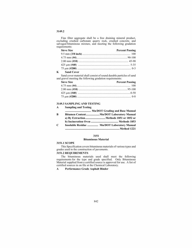
3149.2
842
Fine filter aggregate shall be a free draining mineral product, excluding crushed carbonate quarry rock, crushed concrete, and salvaged bituminous mixture, and meeting the following gradation requirements:
Sieve Size Percent Passing 9.5 mm (3/8 inch) ................................................................... 100 4.75 mm (#4).......................................................................90-100 2.00 mm (#10) ..................................................................... 45-90 425 µm (#40) ........................................................................ 5-35 75 µm (#200) ........................................................................... 0-3
K Sand Cover Sand cover material shall consist of sound durable particles of sand
and gravel meeting the following gradation requirements: Sieve Size Percent Passing 4.75 mm (#4)........................................................................... 100 2.00 mm (#10) ....................................................................95-100 425 µm (#40) .........................................................................0-50 75 µm (#200) ........................................................................... 0-8
3149.3 SAMPLING AND TESTING A Sampling and Testing
.................................... Mn/DOT Grading and Base Manual B Bitumen Content...................Mn/DOT Laboratory Manual
a) By Extraction............................ Methods 1851 or 1852 or b) Incineration Oven ...................................... Methods 1853
C Insoluble Residue ............... Mn/DOT Laboratory Manual ............................................................................Method 1221
3151 Bituminous Material 3151.1 SCOPE
This Specification covers bituminous materials of various types and grades used in the construction of pavements. 3151.2 REQUIREMENTS
The bituminous materials used shall meet the following requirements for the type and grade specified. Only Bituminous Material supplied from a certified source is approved for use. A list of certified sources in on file at the Chemical Laboratory. A Performance Grade Asphalt Binder

3161.2
843
Only Performance Grade (PG) Asphalt Binder is approved for use. The inspection sampling and testing of PG Asphalt Binder shall conform to the Schedule for Materials Control and the Combined State Binder Group Method of Acceptance for Asphalt Binders. B Medium Curing Liquid
Asphalt ......................................................... AASHTO M 82 Modified as follows: In lieu of the viscosity of the residue
requirement, the penetration of the residue at 25ºC (77ºF); 100 g; 5 s, shall be 120 to 250 for all grades. C Rapid Curing Liquid Asphalt......................AASHTO M 81
Modified as follows: In lieu of the viscosity of the residue requirement, the penetration of the residue at 25ºC (77ºF); 100 g; 5 s, shall be 80 to 120 for all grades. D Slow Curing Liquid Asphalt ............... AASHTO M 141-70 E Emulsified Asphalt
Emulsified asphalt shall meet the requirements of AASHTO M 140 (anionic), AASHTO M 208 (cationic) or AASHTO M 316-98 (polymer modified cationic) for the type and grade specified, subject to the following modifications: (1) The ductility at 25ºC (77ºF) shall be a minimum of 600 mm for all
grades. (2) The residue penetration requirements for all hard (h) grades shall be
60-100. (3) The viscosity for HFMS-2, HFMS-2h, and HFMS-2s grades shall
be 50 SFS (Saybolt Furol, seconds) at 50ºC (122ºF), minimum. Polymer modified Cationic Emulsified Asphalt shall meet the requirements of AASHTO M316-98. 3161.3 SAMPLING
Sampling shall be in accordance with the procedures prescribed in AASHTO T-40 and the Schedule for Materials Control. 3161 Coating and Anti-Stripping Additive 3161.1 SCOPE
This Specification covers coating and anti-stripping additives which, when added to bituminous material will improve its coatability on aggregate. 3161.2 REQUIREMENTS A General
The additive shall be completely miscible in all types of bituminous materials and shall show no separation or settlement when the blended

3161.2
844
material is stored for an indefinite length of time at any temperature to which it might be exposed in actual use.
The additive shall have a viscosity of not more than 200 s, Saybolt at 50ºC (122ºF) .
The additive shall have no injurious effect upon the bituminous material. B Stability
The coating or anti-stripping properties of the additive shall not be deleteriously affected by prolonged heating of the blend of additive and bituminous material. C Concentration
The concentration of the additive shall be such that it will meet the requirements of the coating and anti-stripping test, as described below, at a treatment concentration of not more than 1.5 percent. D Packaging
If ordered in drums, the additive shall be shipped in the manufacturer's containers, properly labeled as to the name of the manufacturer, trade name or trade mark, manufacturer's lot number, date of manufacturer and the net mass of the contents.
The additive shall be of uniform consistency from drum to drum in a given shipment. 3161.3 SAMPLING AND TESTING A General
At least one sample shall be taken from each shipment. If a shipment represents more than one lot, each lot may be sampled. B Coating and Anti-Stripping Test B1 Materials
The aggregate used in the test shall consist of 50 percent gray Saint Cloud granite and 50 percent Mendota limestone. It shall be graded to pass a 9.5 mm (3/8 inch) sieve and be retained on a 4.75-mm (#4) sieve, and shall be washed with distilled water until free from dust.
Liquid asphalt, of the kind and grade specified by the Materials Engineer, shall be used in making the test. B2 Procedure ...................................................... AASHTO T 182
For liquid asphalts, the procedure for "wet-aggregates" shall be used.

3166
845
3165 Asphalt Primer for Dampproofing and Waterproofing
Asphalt primer for use with asphalt in dampproofing and waterproofing concrete and masonry surfaces above or below ground level shall conform to AASHTO M 116. 3166 Asphalt for Dampproofing and Waterproofing
Asphalt for use as a mopping coat for dampproofing or as a plying or mopping cement in the construction of a membrane system of waterproofing shall conform to AASHTO M 115. Unless otherwise specified, Type II shall be used.
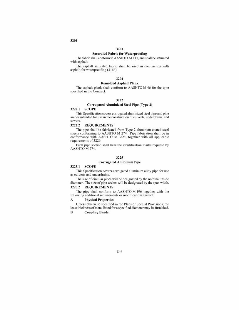
3201
846
3201 Saturated Fabric for Waterproofing
The fabric shall conform to AASHTO M 117, and shall be saturated with asphalt.
The asphalt saturated fabric shall be used in conjunction with asphalt for waterproofing (3166). 3204 Remolded Asphalt Plank
The asphalt plank shall conform to AASHTO M 46 for the type specified in the Contract. 3222 Corrugated Aluminized Steel Pipe (Type 2) 3222.1 SCOPE
This Specification covers corrugated aluminized steel pipe and pipe arches intended for use in the construction of culverts, underdrains, and sewers. 3222.2 REQUIREMENTS
The pipe shall be fabricated from Type 2 aluminum-coated steel sheets conforming to AASHTO M 274. Pipe fabrication shall be in conformance with AASHTO M 36M, together with all applicable requirements of 3226.
Each pipe section shall bear the identification marks required by AASHTO M 274. 3225 Corrugated Aluminum Pipe 3225.1 SCOPE
This Specification covers corrugated aluminum alloy pipe for use as culverts and underdrains.
The size of circular pipes will be designated by the nominal inside diameter. The size of pipe-arches will be designated by the span width. 3225.2 REQUIREMENTS
The pipe shall conform to AASHTO M 196 together with the following additional requirements or modifications thereof: A Physical Properties
Unless otherwise specified in the Plans or Special Provisions, the least thickness of metal listed for a specified diameter may be furnished. B Coupling Bands

3226.2
847
Field joints shall be made with aluminum alloy coupling bands conforming to AASHTO M 196 and to the details shown in the Plans. C Aprons
Aluminum aprons for circular pipes shall be manufactured in accordance with the pertinent requirements of these Specifications for corrugated aluminum pipe and shall conform to the dimensions, design, and details shown in the Plans. D Identification Marks
Each pipe section shall bear the identification marks required by AASHTO M 196. 3225.3 INSPECTION AND TESTING
The sections under Inspection in AASHTO M 196 shall apply. 3226 Corrugated Steel Pipe 3226.1 SCOPE
This Specification covers prefabricated corrugated steel pipe intended to be used in the construction of culverts and underdrains.
For the purposes of this Specification, the unmodified term "pipe" shall be understood to refer to any or all types.
The size of the circular pipe will be designated by the nominal inside diameter. The size of the pipe-arches will be designated by the span width. 3226.2 REQUIREMENTS
Pipe shall conform to AASHTO M 36M for the type specified in the Contract, together with the following modifications or additions thereto: A Blank B Dimensions
Dimensions shall conform to AASHTO M 36M except as modified below: (1) Nominal sheet thickness for each size of pipe shall be as shown in
the Plans. The sheet thickness designated shall be the "Specified Thickness" as given in Table 4 of AASHTO M 218.
(2) Corrugation size shall be 3 8mm by 6.5 mm (1-1/2 inch x 1/4 inch), 68 mm x 13 mm (2-3/4 inch x 1/2 inch), 75 mm by 25 mm (3 inch x 1 inch) , or 125 mm x 25 mm (5 inch x 1 inch) as shown in the Plan. The corrugation dimensions shall be in accordance with Table 1 of AASHTO M 36M for the size furnished.
(3) Corrugation size for spiral ribbed pipe shall be 19 mm x 19 mm x 190 mm (3/4 inch x 3/4 inch x 7-1/2 inch). The corrugation dimensions shall be in accordance with Table 3 of AASHTO M
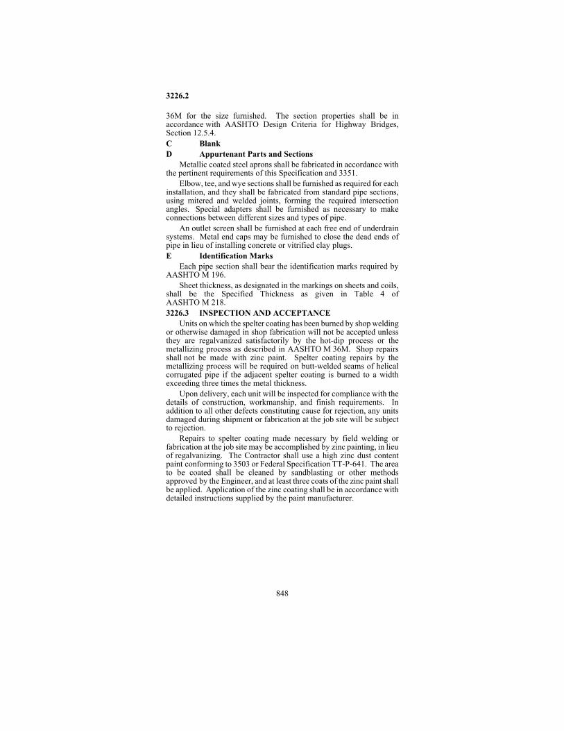
3226.2
848
36M for the size furnished. The section properties shall be in accordance with AASHTO Design Criteria for Highway Bridges, Section 12.5.4. C Blank D Appurtenant Parts and Sections
Metallic coated steel aprons shall be fabricated in accordance with the pertinent requirements of this Specification and 3351.
Elbow, tee, and wye sections shall be furnished as required for each installation, and they shall be fabricated from standard pipe sections, using mitered and welded joints, forming the required intersection angles. Special adapters shall be furnished as necessary to make connections between different sizes and types of pipe.
An outlet screen shall be furnished at each free end of underdrain systems. Metal end caps may be furnished to close the dead ends of pipe in lieu of installing concrete or vitrified clay plugs. E Identification Marks
Each pipe section shall bear the identification marks required by AASHTO M 196.
Sheet thickness, as designated in the markings on sheets and coils, shall be the Specified Thickness as given in Table 4 of AASHTO M 218. 3226.3 INSPECTION AND ACCEPTANCE
Units on which the spelter coating has been burned by shop welding or otherwise damaged in shop fabrication will not be accepted unless they are regalvanized satisfactorily by the hot-dip process or the metallizing process as described in AASHTO M 36M. Shop repairs shall not be made with zinc paint. Spelter coating repairs by the metallizing process will be required on butt-welded seams of helical corrugated pipe if the adjacent spelter coating is burned to a width exceeding three times the metal thickness.
Upon delivery, each unit will be inspected for compliance with the details of construction, workmanship, and finish requirements. In addition to all other defects constituting cause for rejection, any units damaged during shipment or fabrication at the job site will be subject to rejection.
Repairs to spelter coating made necessary by field welding or fabrication at the job site may be accomplished by zinc painting, in lieu of regalvanizing. The Contractor shall use a high zinc dust content paint conforming to 3503 or Federal Specification TT-P-641. The area to be coated shall be cleaned by sandblasting or other methods approved by the Engineer, and at least three coats of the zinc paint shall be applied. Application of the zinc coating shall be in accordance with detailed instructions supplied by the paint manufacturer.

3227.3
849
3227 Bituminous Coated Corrugated Metal Pipe 3227.1 SCOPE
This Specification covers bituminous coated corrugated metal pipe and pipe-arches intended for use in the construction of culverts.
The bituminous coating shall be one of three types, as specified in the Contract, and as defined by the following:
Type A - Fully Bituminous Coated Type B - Half Bituminous Coated, with Paved Invert Type C - Fully Bituminous coated, with Paved Invert
3227.2 REQUIREMENTS The uncoated pipe and connecting bands, together with aprons
when specified, shall conform to 3226. The bituminous coating shall conform to AASHTO M 190, for the
type of coating specified in the Contract. Pipe with Type A coating shall be furnished when no other type is specified.
The coated pipe shall meet AASHTO M 190 for the Shock Test and Flow Test, and shall also pass the Impact Test as described by the following:
A steel ball 57 mm (2-1/4 inches) in diameter and having a mass of 758 g (1.67 pounds) shall be dropped from a height of 2.3 m (7-1/2 feet) through a vertical tube 75 mm (3 inches) in diameter, upon the outside crest of a representative sample. This test shall be conducted with the specimen at a temperature of -1�C (300 F). Failure of the material is indicated by its spalling from the metal on the inside of the pipe or by the formation (on the inside of the pipe) of cracks longer than 13 mm (1/2 inch) from the point of impact. 3227.3 INSPECTION AND TESTING
Sampling and testing will be performed in accordance with the applicable provisions of AASHTO M 190, except as modified by the following: (a) Specimens for the Impervious and Impact tests shall consist of a
segment taken from the coated pipe or coupling band. (b) Bituminous material specimens may be secured from the material
as used or stripped from the coated pipe or band. Inspect the finished product for satisfactory workmanship in all
particulars. The bituminous coating shall be a continuous film: free from cracks, burned areas, blisters, and other injurious defects.

3228
850
3228 Aramid-Bonded Corrugated Steel Pipe 3228.1 SCOPE
This Specification covers corrugated steel pipe having aramid fiber impregnated in the spelter coating during fabrication of the sheets and with a bituminous coating being applied to the pipe after fabrication. When Type C aramid bonded corrugated steel pipe is specified, the pipe shall also have a paved invert. 3228.2 REQUIREMENTS
The pipe and connecting bands shall be fabricated in accordance with 3226, together with the following additional requirements or modifications: A Aramid Bonding
The base metal sheets shall be galvanized on both sides by the hot-dip process, with the spelter being applied at such rate that, when sampled and tested as prescribed, the recoverable quantity of spelter, after the aramid bond has been removed, shall be not less than 460 g per square meter (1-1/2 ounce per square foot). The mass of spelter is the total quantity of galvanizing on both sides of a sheet, expressed as grams per square meter (ounces per square foot) of sheet.
Both sides of the zinc coated metal sheets shall be coated with a layer of aramid fiber applied in sheet form and pressed into the molten zinc. The finished sheets shall show careful workmanship and shall be free from injurious defects such as blisters, areas lacking aramid or zinc spots. B Bituminous Coating
After fabrication of the pipe with aramid bonded sheets, the pipe and coupling bands shall be given a full bituminous coating in accordance with AASHTO M 190 for Type A. C Invert Paving
When a paved invert is specified, the bituminous coated aramid bonded pipe shall also be given the paved invert treatment in accordance with AASHTO M 190 for Type C. D Physical Properties
The finished pipe (coated and paved) shall weigh not less than the theoretical computed mass. E Repair of Damaged Coating
Units on which the coating has been damaged by welding or otherwise damaged in fabrication, shipment, or installation shall be repaired to the Engineer's satisfaction by having the damaged portions cleaned, primed, and recoated with the original materials or approved equals.

3231.1
851
3228.3 INSPECTION AND TESTING Sampling and testing will be performed in accordance with the
applicable provisions of AASHTO M 190, except as modified by the following: (a) Specimens for the impervious and impact tests shall consist of a
segment taken from the coated pipe or coupling band. (b) Bituminous material specimens may be secured from the material
as used or stripped from the coated pipe or coupling-band. (c) Solubility in Trichloroethylene ............................. AASHTO T 44
Inspection of the finished product shall show careful workmanship in all particulars. The bituminous coating shall be a continuous film, free of cracks, burned areas, blisters, and other injurious defects. NOTE: Aramid-Bonded corrugated steel pipe shall conform to this
Specification; however, when this material is specified in the Contract, material meeting 3229, Polymeric Coated Corrugated Steel Pipe, may be furnished as an approved alternate.
3229 Polymeric Coated Corrugated Steel Pipe 3229.1 SCOPE
This Specification covers polymeric coated corrugated steel pipe for use as culverts and underdrains.
Pipe furnished under this Specification shall be fabricated from precoated galvanized steel sheets conforming to AASHTO M 246. Pipe fabrication shall be in conformance with AASHTO M 245 together with all applicable requirements of 3226. 3229.2 REQUIREMENTS
When Type C coating is specified, the polymer coating thickness shall be as shown in the Plans.
In the absence of a prescribed coating type, the pipe shall be furnished with Type B coating. 3231 Galvanized Steel Structural Plate for Pipe, Pipe-Arches, and Arches 3231.1 SCOPE
This Specification covers galvanized corrugated steel structural plate and fasteners for use in the construction of pipe, pipe-arches, underpasses, and special shapes for field assembly.

3231.2
852
3231.2 REQUIREMENTS The structural plates and fasteners shall conform to
AASHTO M 167, together with the following additional requirements or modifications: A Fabrication
The plate thickness and section modulus shall be as shown in the Plans, or a different thickness and section modulus providing equal or greater strength may be furnished. The plate thickness designated shall be the specified thickness as given in Table 3 of AASHTO M 167.
The size and shape of the plates shall be such that the finished structure will have the dimensions shown in the Plans, and that either the longitudinal or transverse seams will be staggered in the finished structure.
All bolt holes shall be punched before the sheets are galvanized. B Workmanship and Finish
All plates shall show careful and finished workmanship. Among other causes for rejection, the following defects are specified as constituting poor workmanship, and the presence of any of these defects in an individual plate or in general in any shipment shall constitute sufficient cause for rejection: (1) Incorrect plate shape, or unevenly lined or spaced bolt holes. (2) Plates with ragged edges, or with illegible or improper markings. (3) Bruised, scaled, broken, or improperly repaired spelter coating. (4) Dents or bends in the metal plate. 3231.3 INSPECTION AND ACCEPTANCE .................... 3226.3 3233 Aluminum Alloy Structural Plate for Pipe, Pipe-Arches, and Arches 3233.1 SCOPE
This Specification covers corrugated aluminum alloy structural plate, accessories and fasteners for use in the construction of pipe, pipe-arches, arches, and special shapes, for field assembly. 3233.2 REQUIREMENTS
The structural plates, accessories and fasteners shall conform to AASHTO M 219, together with the following additional requirements or modifications: A Fabrication
Plate thickness, pipe shape, sheet fabrication details, and assembly bolting shall be as shown in the Plans. B Workmanship and Finish

3236.2
853
All plates shall show careful and finished workmanship. Among other causes for rejection, the following defects are specified as constituting poor workmanship, and the presence of any of these defects in an individual plate or in general in any shipment shall constitute sufficient cause for rejection: (1) Incorrect plate shape, or unevenly lined or spaced bolt holes. (2) Plates with ragged edges, or with illegible or improper markings. (3) Dents or bends in the metal plates. 3236 Reinforced Concrete Pipe 3236.1 SCOPE
This Specification covers reinforced concrete pipe of circular, arch, elliptical, or special shape and design, with appropriate appurtenances, used in the construction of culverts, sewers or underpasses. 3236.2 REQUIREMENTS
Reinforced concrete pipe shall conform to the following AASHTO Specifications, as identified by design, and subject to the additional requirements or modifications contained herein: (a) Circular Pipe .......................................................AASHTO M 170 (b) Pipe-Arch ............................................................AASHTO M 206 (c) Elliptical Pipe......................................................AASHTO M 207
Concrete aprons shall be manufactured in conformance with the Plans, together with the Specifications applying to the pipe design to which they are fitted.
Concrete cattle pass units shall be manufactured in conformance with the Plans and the pertinent requirements of AASHTO M 170 for Class III pipe of equivalent wall thickness. Cattle pass and apron units will not be subjected to external load bearing tests. A Materials A1 Aggregate quality ........................................ 3126 and 3137 A2 Form release agents ..................................................... 3902 A3 Portland cement ......................................... AASHTO M 85
Cement substitutions and the use of admixtures in accordance with 2461.3D and 2461.3E will be permitted except that the calendar date restrictions on their use shall not apply.
Positive slump (wet cast) concrete shall be air-entrained by using either an air-entraining Portland cement or by using standard Portland cement plus an approved air-entraining admixture. The air content shall be maintained within the range of 5 to 8 percent.

3236.2
854
A4 Metal Reinforcement ................................................... 2472 B Pipe Design
Design requirements for pipe shape, diameter, wall thickness, compressive strength of the concrete, and the quantity and type of circumferential reinforcement shall be as shown in the Plans for the different classes of pipe. However, pipe manufactured in conformance with the AASHTO Design Tables will be accepted in the case of elliptical pipe. Where AASHTO design requirements differ from those specified in the Plans, compliance shall be with the Plans, unless the different AASHTO requirements are approved as an alternate prior to manufacture.
Placement of reinforcement shall be in accordance with applicable AASHTO Specification, except as otherwise required by the Plans or approved by the Engineer. Elliptical reinforcement will not be permitted in circular pipe. Wire mesh shall be lapped a minimum of one full mesh or twenty wire diameters, whichever is greater. Laps may be welded for pipe, however, only welders approved by the Materials Engineer may perform this task.
When pipe are furnished for installations where rubber gasket seals are required, the tongue and groove or alternative offset joint design shall be as indicated in the Plans. All surfaces of the joint upon which the gasket may bear shall be smooth and free of spalls, cracks, fractures, and other imperfections that would adversely affect the performance of the rubber gasket sealer. C Manufacture
The Contractor shall use products fabricated in a precast concrete fabrication plant that has been granted plant pre-approval for acceptance of precast concrete products by the Materials Engineer. This program is based on the American Concrete Pipe Association Quality Assurance Manual. Under this program Fabricators are required to set up their total production on a pre-approved basis and certify that products furnished to the Contractor comply with the Contract requirements. Acceptance of products under this program will be limited to each precast concrete Fabricator and to each of the several plants as specifically and formally agreed to by the Materials Engineer. The approval is limited to the identified sizes of round pipe, arch pipe, and appurtenances.
The concrete units shall be cured by the steam or water curing methods, unless the use of a sealing membrane or other effective methods are specifically approved by the Engineer. When steam curing is used, atmospheric temperature in the curing chamber shall not exceed 70ºC (160ºF). The concrete units shall be protected from freezing, after being cast and until the curing is completed.
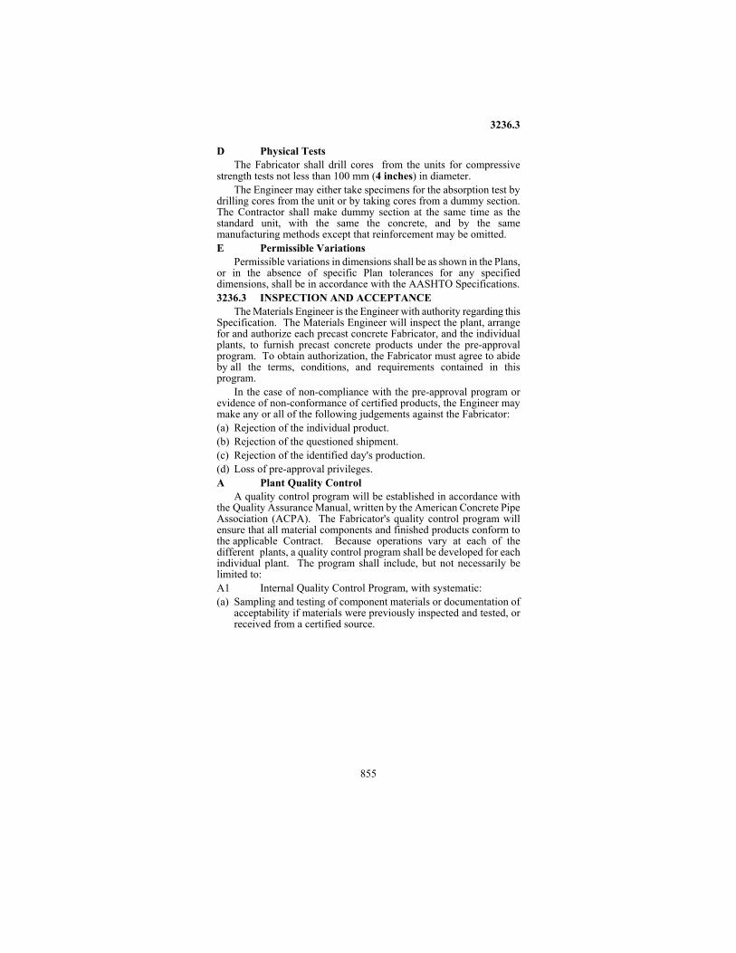
3236.3
855
D Physical Tests The Fabricator shall drill cores from the units for compressive
strength tests not less than 100 mm (4 inches) in diameter. The Engineer may either take specimens for the absorption test by
drilling cores from the unit or by taking cores from a dummy section. The Contractor shall make dummy section at the same time as the standard unit, with the same the concrete, and by the same manufacturing methods except that reinforcement may be omitted. E Permissible Variations
Permissible variations in dimensions shall be as shown in the Plans, or in the absence of specific Plan tolerances for any specified dimensions, shall be in accordance with the AASHTO Specifications. 3236.3 INSPECTION AND ACCEPTANCE
The Materials Engineer is the Engineer with authority regarding this Specification. The Materials Engineer will inspect the plant, arrange for and authorize each precast concrete Fabricator, and the individual plants, to furnish precast concrete products under the pre-approval program. To obtain authorization, the Fabricator must agree to abide by all the terms, conditions, and requirements contained in this program.
In the case of non-compliance with the pre-approval program or evidence of non-conformance of certified products, the Engineer may make any or all of the following judgements against the Fabricator: (a) Rejection of the individual product. (b) Rejection of the questioned shipment. (c) Rejection of the identified day's production. (d) Loss of pre-approval privileges. A Plant Quality Control
A quality control program will be established in accordance with the Quality Assurance Manual, written by the American Concrete Pipe Association (ACPA). The Fabricator's quality control program will ensure that all material components and finished products conform to the applicable Contract. Because operations vary at each of the different plants, a quality control program shall be developed for each individual plant. The program shall include, but not necessarily be limited to: A1 Internal Quality Control Program, with systematic: (a) Sampling and testing of component materials or documentation of
acceptability if materials were previously inspected and tested, or received from a certified source.

3236.3
856
(b) Inspection of product manufacturing including: (1) Reinforcing steel fabrication and placement. (2) Concrete mix design and proportioning. (3) Concrete placement and consolidation. (4) Concrete curing.
(c) Testing of finished products: (1) Strength of concrete cylinders. (2) Three-edge-bearing test (round pipe). (3) Absorption and air content of pipe cores. A core will be
required once during the year from pipe of each class, size, and type of manufacture, to verify the correct steel placement.
(d) Final visual inspection and marking (stamping). (e) Maintenance of plant facilities and equipment in good, accurate
condition. A2 Resident Quality Control Technicians, shall be appointed by
the Fabricator to conduct the quality control testing. They shall:
(a) Be a trained/certified (MN/DOT Level I, Concrete Field Tester or ACI, Grade I) quality control technician and is responsible for insuring the conformance of all pre-approved products to the requirements.
(b) Be knowledgeable of the; (1) Plans and Specification requirements. (2) Product manufacturing operations. (3) Significance of the Specification requirements in producing
quality products. (c) Have authority to correct and stop or to stop any operation that is
found to be causing non-conforming attributes, and to reject all products not meeting these requirements.
(d) Ensure that all requirements which relate to producing pre- approved products are continuously met.
(e) Be responsible for contacting the Mn/DOT inspector for prior approval of all repairs of more than ten percent of the respective surface, inside or outside.
A3 Equipment Calibration................................ 1901, 2461.4D4 A4 System of Record Keeping, shall include but not be limited
to: (a) Component material sources and their acceptable quality test
results, authorized certification or evidence of inspection and testing.

3236.3
857
(b) Test results covering product manufacture and the finished product as listed in the records section of the APCA manual.
(c) Records of manufactured products, by: (1) Date. (2) Size. (3) Class.
(d) A running inventory of pre-approved products in stock. (e) Equipment calibration reports. B Quality Assurance
A quality assurance program of random sampling, testing, and inspection will be performed by a representative of the Materials Engineer at each pipe plant operating under this program. This quality assurance program will consist of but is not limited to: (1) Random sampling and testing of the materials used in the
manufacture of pre-approved products. (2) Random sampling and testing of the pre-approved pipe produced. (3) Observing of the manufacturing process. (4) Review of the manufacturer's quality control tests, inspection,
records, and stockpiling practices. (5) Inspection of pre-approved product inventory.
The inspector should visit the Fabricator's plant at least once per week to perform the tasks listed above. The records file should be checked once a month, and a spot inspection by the Engineer should be done every 6 months. (At least once during seasonal production).
All units will be subject to final inspection upon delivery. C Testing Rates
The Fabricator's testing for the quality control program may be conducted by the manufacturer's own certified personnel, a Professional Engineer, or an independent inspection laboratory.
Because the quality control program must be tailored to each individual plant, the schedule and testing rates may vary from plant to plant. The following is offered as guidelines for the sampling, testing, and inspection of materials and finished products to be included in the quality control program. C1 Concrete - The Fabricator shall test the concrete on each mix
used as follows: (a) Air Entrainment - one test per day for each positive slump mix. (b) Concrete Strength - concrete shall reach 100 percent of the design
strength prior to shipment. The Fabricator shall test concrete cylinders cured with the product (control cylinders), or cores from the product itself. These tests shall be conducted in accordance with AASHTO or ASTM standard procedures.

3236.3
858
STANDARD CYLINDERS (Department tested at 28 days, moist cured) will be made;
- Positive slump: one cylinder per 8 hours production or any fraction thereof. - Zero slump: one cylinder per week.
C2 Load Bearing Test The Fabricator shall conduct Three-Edge Bearing tests in
accordance with AASHTO M170, on each size and class of pipe at the rate of the following schedule. Size Range mm (inch)
Class Range
Test Rates
300 to 450 (12 to 18 inches)
Class 5 & below
1 per 1500 meters (1 per 5000 feet)
525 to 1200 (21 to 48 inches)
Class 5 & below
1 per 900 meters (1 per 3000 feet)
1350 to 1800 (54 to 72 inches)
Class 4 & below
1 per 600 meters (1 per 2000 feet)
1350 to 1800 (54 to 72 inches)
Class 5
1 per 300 meters (1 per 1000 feet)
1950 to 2400 (78 to 96 inches)
All Classes
1 per 300 meters (1 per 1000 feet)
The schedule of testing shall commence anew whenever the mix
design is changed, the production system is shut down for major repairs and renovations, or at the beginning of a new production season.
All pipe shall have developed the specified D-load prior to shipment.
The Fabricator shall give the inspector 48 hour advance notice of the testing being performed. The Engineer reserves the right to select pipe to be tested. The Fabricator may be required to perform additional testing as directed by the Engineer at no additional cost.
For pipe requiring shear steel, notify the inspector at the beginning of a production run. Shear steel must be pinned. This will include, "B" wall pipe, 1350 mm (54 inches), Class 5 and larger. D Pipe Marking
In addition to the marking requirements of AASHTO M170, the word "Certified" and the manufacturing plant identification, shall be stamped inside each unit 600 mm (24 inches) in diameter or larger and outside on each unit less than 600 mm (24 inches) in diameter. Each unit of pipe, or allied product, so marked identifies the unit as being in conformance with all requirements.

3238.2
859
All products manufactured for special projects not meeting the standards of the pre-approved program must be stamped with an identifying Project number or buyers name.
Pre-approved shipments may be accepted if the product is marked CERTIFIED PLANT COMPANY (Actual size 100 mm x 100 mm (4 inches x 4 inches); the company identification, the individual production plant, and that the product is "certified")
The manufacturer of pre-approved materials shall furnish, with each shipment, a certified bill of materials or invoice which identifies the project number, Contractor, the type of material, the number of pieces of each size, class and length of pipe. One copy of the certification document shall accompany the shipment for the Project Engineer. The certification shall be signed by a designated, responsible company representative and shall be stated as follows:
"The materials itemized in this shipment are certified to be in compliance with the applicable Minnesota Department of Transportation Specifications and the Project Plans."
_____________________________ Authorized Signature and Date
The manufacturer of pre-approved materials shall furnish at the end of each calendar year or at regular intervals during the year, an itemized summary report of the year’s shipments to each project, detailing project number, contractor, product shipped, number of pieces, length and tonnage.
Shipment of pre-approved products shall not be made until all quality control tests and inspections have been completed and the materials are found to comply with all requirements. E Stockpiling
Products approved for shipment shall be stockpiled in a manner such that each piece is accessible for quality assurance inspection. The Fabricator shall stockpile special (non-pre-approved) stock in areas separate from the pre-approved stock. 3238 Precast Concrete Box Culverts 3238.1 SCOPE
This Specification covers the construction of precast concrete single and multi-cell box culverts, headwalls, and aprons at a precasting plant. 3238.2 REQUIREMENTS A Fabrication Drawings, Falsework and Forms
3238.2
860
Prior to fabrication of these units, the Contractor shall furnish shop drawings to the Engineer for review by the Office of Bridges and Structures to facilitate the Department's inspection. These drawings shall be complete and comprehensive, and shall include the number of mats, their makeup and configuration, as well as stirrup sizes and spacing for each type of segment required by the Plans.
The minimum length of individual sections shall be 1.2 m (4 feet) with provisions for each section to be tied to the adjacent section with concrete pipe ties as detailed on Mn/DOT Standard Plate 3145 and as required by the Plans. B Materials B1 Concrete ....................................................................... 2461
Mix designations shall be as indicated in the Plans for the specific Items of work. B2 Reinforcement Bars ..................................................... 3301 B3 Steel Fabric .................................................................. 3303
When laps are required, the lap shall be at least one full mesh plus 50 mm (2 inches) for transverse laps or one full mesh plus 50 mm (2 inches) plus 2 end overhangs for longitudinal laps. C Forms
Forms shall be designed to withstand the pressure due to concrete, vibration, and impact without distortion. They shall be set and maintained in a mortar tight condition, free of warp and on a rigid foundation. Joints in the sectional forms shall have a tight fit without offset. Forms shall be set so that the dimensions of the precast unit will conform to the Plans. Forms which preclude the obtaining of dimensional tolerances shall be repaired or replaced prior to casting additional sections of the precast units.
The face of the forms in contact with the concrete shall be treated with form coating material meeting 3902 before the form is set in position. Forms shall be thoroughly cleaned of accumulations of oil, concrete, and other substances prior to use. D Reinforcement Steel
Reinforcement steel shall be accurately placed in the position shown in the Plans, secured with chairs, supported, and tied all in accordance with 2472. The concrete cover on reinforcement bars, at any point, shall not be less than 40 mm (1-1/2 inches) or as stated in the Plans. Reinforcement supports in contact with the precasting forms shall be stainless steel, plastic tipped, or hot or mechanically galvanized. Such coatings shall extend at least 25 mm (1 inch) from the form surface. Tack welding of reinforcement is not permitted unless Grade A706 steel is used and then only when specifically approved by the Materials Engineer.
3238.2
861
E Placement of Concrete Concrete for each precast unit shall not be placed until the forms
and steel placement have been inspected by the Department's representative.
The concrete in each precast unit shall be placed without interruption. The Concrete shall be vibrated internally, externally, or both, as required to produce uniformly dense concrete and in such a manner as to avoid displacement of enclosures or steel units. Internal vibration shall conform with 2401.3 except that internal vibrators shall have a vibrating head not greater than 32 mm (1-1/4 inch) in diameter and shall operate at a frequency of not less than 100 Hz (6000 impulses per minute). F Concrete Curing
The precast concrete units shall be cured by the steam or water curing methods, unless the use of sealing membrane or other methods are authorized by the Engineer. When steam curing is used, it shall be in accordance with 2405.3. The Fabricator shall supply a temperature recording device when a steam cure is used. The device shall be placed as directed by the Engineer, and the records shall be provided to the Engineer.
Concrete shall be cured until a minimum compressive strength of 17 Mpa (2500 pounds per square inch) is obtained as evidenced by control cylinders cured with the product. Control cylinders may be cured apart from the precast unit if measures are taken to ensure that curing conditions for the cylinder are the same as for the precast unit. These measures will include temperature recording devices for both the control cylinders and for the precast concrete unit. G Concrete Finishing
All formed surfaces of the precast units shall have a uniform dense surface finish. Immediately after removal of the forms, the concrete surfaces shall be examined for areas of unsound concrete and defective surfaces due to faulty forms or form assembly, improper concrete placement, improper form removal, and other causes.
Concrete with porosity, honeycomb, or segregated materials shall be removed and replaced, but not until the Department's representative has viewed the extent of the defective concrete and has approved the method of repair and the materials to be used and provided such repair is performed in a timely manner.
Minor surface cavities or irregularities which do not impair the service value of the precast unit and which are satisfactorily repaired shall not constitute cause for rejection. Only mortar approved by the Engineer may be used to repair surface defects.

3238.3
862
3238.3 INSPECTION AND ACCEPTANCE The Materials Engineer is the Engineer with authority regarding this
Specification. Plant inspection will be made of the units and each approved unit
will be stamped with the official mark of the Department. At least 24 hours notice shall be provided before units are to be shipped. All authorized repairs must be made before the unit is stamped, and no units shall be delivered without the official stamp of approval. All units will be subject to final inspection upon delivery.
The inside of each box section shall be marked to identify the Project Number, overfill height, and segment number as shown on the Plans. 3241 Plastic Truss Pipe
Plastic truss pipe, together with the couplings and fittings thereof, shall comply with ASTM D 2680, Acrylonitrile-Butadiene-Styrene (ABS) and Polyvinyl Chloride (PVC) Composite Sewer Piping. Unless otherwise specified, joint type shall be optional with the Contractor.
Each shipment of pipe shall be accompanied by a Certificate of Compliance, furnished by the pipe manufacturer, in accordance with 1603. 3245 Thermoplastic Pipe
Thermoplastic pipe and fittings shall meet one of the following: AASHTO M 278, Class PF 50, Polyvinyl Chloride (PVC) Pipe; ASTM D 2751, Acrylonitrile-Butadiene-Styrene (ABS) Sewer Pipe, SDR 35; ASTM D 3034, Type PSM PVC Sewer Pipe, SDR 35; ASTM F 758, Smooth-Wall PVC, Type PS 46; or ASTM F 949, PVC Corrugated Sewer Pipe.
When perforated pipe is specified, perforations shall conform to the applicable Specification. Unless otherwise specified, perforations shall be 5 to 10 mm (0.2 to 0.4 inch) diameter, spaced 75 mm (3 inches) center-to-center, and have two rows of holes for 100 mm (4 inch) pipe and four rows for 150 to 250 mm (6 to 10 inch) pipe. When perforation dimensions are not indicated in the applicable Specification, they shall conform to any of the configurations indicated for other pipe types permitted herein. Unless otherwise specified, joint type shall be optional with the Contractor.
Each shipment of pipe shall be accompanied by a Certificate of Compliance, furnished by the pipe manufacturer, in accordance with 1603.

3253
863
3247 Corrugated Polyethylene Pipe
Corrugated polyethylene pipe, together with the couplings and fittings, shall comply with AASHTO M 294, and Design Section 18 of the AASHTO Standard Specifications for Highway Bridges.
Each shipment of pipe shall be accompanied by a Certificate of Compliance, furnished by the pipe manufacturer, in accordance with 1603.
Storage and handling of corrugated polyethylene pipe shall be in accordance with the manufacturer's recommendations except that in no case shall corrugated polyethylene pipe be exposed to direct sunlight for a total time of more than 6 months after fabrication. Damaged pipe shall not be used. 3251 Clay Pipe
Clay pipe shall conform to AASHTO M 65 for the size, type, and class specified, subject to the following provisions: (1) Compression joint shall conform to ASTM C 425. (2) When requested by the Engineer, the pipe manufacturer shall
furnish a Certificate of Compliance covering the material delivered. 3252 Cast Iron Soil Pipe
Cast iron soil pipe and fittings shall conform to ASTM A 74 for the class specified. 3253 Nonreinforced Concrete Pipe
Nonreinforced concrete pipe shall conform to the applicable requirements of 3236 and AASHTO M 86 for the specified diameter and strength class, and when perforated pipe is specified the pipe shall also conform to the applicable requirements of AASHTO M 175 for the perforation type specified. Class 1 pipe may be furnished unless a higher strength class is specified.
To determine acceptability of the pipe, crushing tests may be made on concrete cylinders in lieu of the three-edge bearing test, in which case the concrete shall develop a compressive strength of not less than 21 Mpa (3000 pounds per square inch) at 14 days.

3276
864
3276 Drain Tile
Concrete drain tile shall conform to AASHTO M 178. Clay drain tile shall conform to AASHTO M 179 and the class may be Standard unless otherwise specified. 3278 Corrugated Polyethylene Drainage Tubing
Corrugated polyethylene (PE) tubing and fittings shall meet AASHTO M 252. Each shipment of tubing shall be accompanied by a Certificate of Compliance, furnished by the manufacturer, in accordance with 1603.
3301.3
865
3301 Reinforcement Bars
3301.1 SCOPE This specification covers deformed and plain reinforcing steel
intended for use as reinforcement in concrete construction. 3301.2 REQUIREMENTS
Reinforcement bars (other than wire) shall conform to one of the following AASHTO Specifications, as would apply to the size, type and grade required: (a) Billet Steel Bars.................................................... AASHTO M 31 (b) Rail Steel Bars ....................................................AASHTO M 42 (c) Axle Steel Bars ....................................................AASHTO M 53
Type and grade requirements may be indicated in the Plans or Specifications for the class of work involved. If not otherwise specified, reinforcement bars shall be Grade 420 Mpa (60) of any type except as modified by the following provisions: (a) Reinforcement bars for use in any part of a concrete bridge
(including precast units thereof), box culvert, or retaining wall, shall be deformed billet steel bars.
(b) Reinforcement bars for use in all other concrete structures except those described above shall be deformed bars of any type and grade.
(c) Any bar upon which welding is permitted or required shall meet ASTM A 706. (Note: All A 706 bars have a 414 Mpa (60,000 psi) minimal yield point.) When epoxy coated reinforcement bars are specified, coating shall
be in conformance with AASHTO M 284. Application of epoxy coating shall be made in a fusion bonded epoxy coating plant that has been granted "Certification" by the Concrete Reinforcing Steel Institute, or an organization approved by the Materials Engineer.
The plant's quality control office shall maintain documentation containing the data required by certification. This documentation shall contain test data and measurements taken at times and locations approved by the Engineer, ensuring that monitoring, by personnel not directly involved in production, is sufficient for compliance with approved procedures.
All reinforcement shall be fabricated, stored, and placed in accordance with 2472. 3301.3 INSPECTION AND ACCEPTANCE
If the Engineer's review of fabrication work discloses that approved procedures are not being followed, the Fabricator shall immediately correct the procedure. The Engineer will determine what additional

3301.3
866
testing must be done by the Fabricator or, if necessary, what part of the work must be repaired or replaced. 3302 Dowel Bars
Dowel bars shall be fabricated from Grade 40 or 60 steel in accordance with AASHTO M31, M42 or M53 and be epoxy coated in conformance with AASHTO M284.
Shearing will be permitted provided the coating is not damaged and subject to permissible deformation. Any deformation larger than true shape shall not exceed 1 mm (0.04 inch) increase in diameter or thickness and shall not extend more than 10 mm (0.40 inch) from the dowel end. 3303 Steel Fabric
Steel fabric for concrete reinforcement shall conform to AASHTO M 55 or M 221 for plain or deformed wire as specified, with the exception that oversize wire may be permitted, in which case the limitation on the difference between the maximum and minimum diameters shall not apply. Unless otherwise specified, the fabric may be furnished in either flat sheets or rolls. 3305 Spiral Reinforcement
Wire used in the fabrication of spiral cage reinforcement for round columns shall be Cold Drawn Steel Wire for Concrete Reinforcement conforming to AASHTO M 32 for the size shown in the Plans.
In lieu of the cold drawn steel wire specified above, plain or deformed Grade 60 Billet steel bars conforming to 3301, may be substituted.
When the spiral reinforcement is to be spliced by welding, the carbon content shall not exceed 0.28 percent nor shall the manganese content exceed 1.00 percent, as determined from laboratory check tests. 3306 Low Carbon Structural Steel 3306.1 SCOPE
This Specification covers carbon steel shapes, plates, bars, sheets, and strips.

3308.2
867
3306.2 REQUIREMENTS A General
Steel furnished under this Specification shall conform to the following ASTM requirements, the tensile requirements, and 3308.
Steel shapes, plates, and bars shall conform to ASTM A 709/A 709M, Grade 250 (36). Steel sheets and strips shall conform to ASTM A 570/A 570M, Grade 250 (36). B Tensile Requirements
Tensile tests are required for all sizes of shapes and bars. 3308 General Requirements for Structural Steel 3308.1 SCOPE
This Specification shall apply to all steel furnished for structural applications as referenced in 2471. 3308.2 REQUIREMENTS A General
All steel furnished for structural applications shall comply with the requirements of ASTM A 6/A 6M, subject to the additional requirements or modifications set forth herein. B Chemical Analysis
The type of steel shall be noted on the mill test report. C Metallurgical Structure
Structural steel furnished for use in major structural components as defined in 2471.3D1 shall be fully killed and have a fine austenitic grain size. D Quality
Weld repair of the base metal is not permitted without written approval of the Engineer.
Injurious defects such as pipes, seams, unapproved repairs, laminations, cracks, and segregations shall be corrected by the Contractor. Correcting defects and any testing necessary to determine the extent of the defects or to confirm the adequacy of repairs shall be done as required by the Engineer and at no expense to the Department. Defects on plates or rolled beams that reduce the thickness of the material in any given section by more than 30 percent shall be cause for rejection of the material. E Tensile Test
For rolled beams, tensile specimen shall be taken from the mid-thickness of the flange and be oriented longitudinally to the rolling

3308.2
868
direction. The location and orientation of tensile specimens shall be noted on the mill test report. F Impact Tests
Structural steel furnished for use in major structural components as defined in 2471.3D1 shall be impact tested. Impact testing will not be required for minor structural components unless it is specifically required by the Contract.
Structural steel that is impact tested shall meet the requirements of ASTM A 709/A 709M for zone 3 welded material. 3309 High Strength Low Alloy Structural Steel 3309.1 SCOPE
This Specification covers high strength, low alloy structural steel shapes, plates, bars, sheets, and strips. 3309.2 REQUIREMENTS
Shapes, plates, and bars furnished under this Specification shall conform to ASTM A 709/A 709M, Grade 345W (50W), and 3308.
Sheet and strip supplied to this Specification shall conform to ASTM A 606, Type 4 hot rolled material and 3308, except that the minimum yield strength shall be 345 MPa (50,000 psi).
Where the Contract does not specify the type of steel to be furnished, the supplier may furnish the material in any type listed. However, all material for any individual unpainted structure shall be of the same type. 3310 High Strength Low Alloy Columbium-Vanadium Steel 3310.1 SCOPE
This Specification covers high strength, low alloy columbium-vanadium steel shapes, plates, bars, sheets, and strips. 3310.2 REQUIREMENTS
Shapes, plates, and bars furnished under this Specification shall conform to ASTM A 709/A 709M, Grade 345W (50W), and 3308.
Sheet and strip supplied to this Specification shall conform to ASTM A 607, Class 2 hot rolled and 3308 except that the minimum yield strength shall be 345 Mpa (50,000 psi).

3313
869
3312 Stainless Steel
Stainless steel plates, sheet and strip shall conform to ASTM A 167 for Type 302 or 304 material. The finish shall be No. 4 polish except for sheet and strip used in bearing and modular expansion joint assemblies in which case the finish shall be No. 8 polish.
Stainless steel bars shall conform to ASTM A 276 for Type 302 or 304, Condition A (annealed). For pin stock, refer to 3314, Type IV.
Stainless steel for free machining applications (bolt stock, etc.) shall conform to ASTM A 582/A 582M for Type 303, Condition A, cold finished, unless otherwise specified. For bolt stock, refer to 3391.2E.
For descaling and cleaning stainless steel surfaces use ASTM A 380.
If the stainless steel is to be welded, the carbon content shall be no greater than 0.03 percent. 3313 Hot Rolled Bar Steel
Rounds, squares, hexagons, or flats supplied under this Specification shall be one of the following types, as specified in the Contract.
Type I - Carbon Bar Steel Hot rolled carbon bar steel shall conform to ASTM A 576 for Grade
1035 or Grade 1040. In addition, the material shall have a minimum yield strength of 310 Mpa (45,000 psi), a minimum ultimate strength of 420 Mpa (60,000 psi), and a minimum elongation of 20 percent in 50 mm (2 inches).
Type II - Alloy Bar Steel Hot rolled alloy bar steel shall conform to ASTM A 322 for
corresponding Grade AISI A 4140 or 4142. In addition, the material shall have a minimum yield strength of 380 Mpa (55,000 psi), a minimum ultimate strength of 585 Mpa (85,000 psi), and a minimum elongation of 15 percent in 50 mm (2 inches).
Type III - Pre-Heated Alloy Bar Steel (Rounds) Hot rolled, pre-heat treated alloy bar steel shall conform to the
following requirements: The base material shall conform to ASTM A 322 for corresponding Grade AISI A 4140 or 4142. The stock shall be pre-heat treated by quenching and tempering to meet the physical properties in Table 3313-1, but shall still be in a machinable condition.

3313
870
TABLE 3313-1 HOT ROLLED BAR STEEL
Diameter mm (inches)
Minimum Tensile Strength Mpa (psi)
Minimum
Yield Strength Mpa (psi)
Min. Elong. in 50 mm
(2 in.) %
Brinell
Hardness
Under 63 (2-1/2)
860 (125,000)
725 (105,000)
16
269-321
63 to 100 (2-1/2 to 4)
795 (115,000)
655 (95,000)
16
255-321
Over 100 (over 4)
760 (110,000)
585 (85,000)
16
250-321
Type IV - Corrosion Resisting Cold Finished Rounds Hot rolled stainless steel bars used for bridge pins shall be cold
finished to size in a fabrication shop and shall conform to the following: The base material shall be annealed and hot finished free machining, Type No. 303, as specified in ASTM A 276. After turning, the maximum size furnished shall not exceed 140 mm (5-1/2 inches) in pin diameter. 3314 Cold Finished Bar Steel
Rounds, squares, hexagons or flats, supplied under this Specification shall be one of the following types, as specified in the Contract.
Type I - Carbon Bar Steel Cold finished carbon bar steel shall conform to ASTM A 108 for Grade C 1035. In addition, the following strength requirements shall apply unless otherwise specified.
Rounds through 75 mm (2-7/8 inches) diameter and all hexagons and squares up to 75 mm (3 inches) maximum dimension across flats shall have a minimum yield strength of 420 Mpa (60,000 psi), an ultimate strength of 485 Mpa (70,000 psi) minimum, and a minimum elongation of 10 percent in 50 mm (2 inches).
Rounds over 73 mm (2-7/8 inches) in diameter and all flats, hexagons and squares over 75 mm (3 inches) maximum dimension across flats shall have a minimum yield strength of 310 Mpa (45,000 psi), an ultimate strength of 420 MPa (60,000 psi) minimum, and a minimum elongation of 20 percent in 50 mm (2 inches).

3315.2
871
Type II - Alloy Bar Steel Cold finished alloy bar steel shall conform to ASTM A 331 for corresponding grade AISI A 4140 or 4142, annealed and cold finished.
In addition the following strength requirements shall apply, unless otherwise specified.
Rounds through 75 mm (2-15/16 inches) in diameter and all hexagons and squares up to 75 mm (3 inches) maximum dimension across flats shall have a minimum yield strength of 520 MPa (75,000 psi), an ultimate strength of 655 MPa (95,000 psi) minimum, and a minimum elongation of 10 percent in 50 mm (2 inches).
Rounds over 75 mm (2-15/16 inches), all hexagons, squares and flats over 75 mm (3 inches) maximum dimension across flats shall have a minimum yield strength of 380 MPa (55,000 psi), an ultimate strength of 585 MPa (85,000 psi) minimum, and a minimum elongation of 15 percent in 50 mm (2 inches).
Type III - Pre-Heat Treated Alloy Bar Steel (Rounds) Cold finished pre-heat treated alloy bar steel shall conform to the
following requirements. The base material shall conform to ASTM A 331 for corresponding Grade AISI A 4140 or 4142. The stock shall be pre-heat treated by quenching and tempering to meet the physical properties in Table 3313-1, but shall still be in a machinable condition.
Type IV - Corrosion Resisting Cold Finished Rounds Cold finished stainless steel rounds for use as bridge pins shall
conform to ASTM A 276 for Type No. 316, annealed and centerless ground. The maximum size furnished shall not exceed 115 mm (4.5 inch) in pin diameter. 3315 Steel Forgings 3315.1 SCOPE
Material furnished under this Specification shall conform to one of three types, as set forth herein and as specified in the Contract. When the Contract fails to specify a type, Type I shall be furnished. 3315.2 REQUIREMENTS A Material Requirements
Type I - Carbon Steel Forgings Carbon steel forgings shall conform to ASTM A 668/A 668M
Class D, forged from blooms, billets, bars, or slabs meeting ASTM A 711 for Grade C 1035 or Grade C 1040.
Type II - Alloy Steel Forgings
3315.2
872
Alloy steel forgings, for sizes up to and including 225 mm (9 inches) in thickness or diameter, shall conform to ASTM A 668/ A 668M Class G.
Alloy steel forgings, for sizes over 225 mm (9 inches) in thickness or diameter, shall conform to ASTM A 668/A 668M, Class H.
Alloy steel forgings shall be made from alloy steel blooms, billets, bars, or slabs meeting ASTM A 711 for Grades A 4140, A 4142, or A 4145.
Type III - Corrosion Resisting Steel Forgings Corrosion resisting steel forgings shall be made from billets or bars
primarily produced for reforging in compliance with ASTM A 314, Type No. 316.
The steel forgings shall meet the applicable physical and chemical requirements for hot-rolled materials as specified in ASTM A 276. The material shall be Type 316, fully annealed in such a manner as to develop maximum corrosion resisting properties. The forgings shall have a workmanlike finish and shall be free from injurious defects. B Machine Finishing
All machining shall be done after the annealing process has been completed. For finishing, refer to 2471.
A 50 mm (2 inch) round hole shall be bored longitudinally through the center of each type (carbon steel, alloy steel or corrosion resisting steel) pin roller that measures over 225 mm (9 inches) in diameter unless otherwise shown in the Plans or specified in the Contract. C Test Requirements
All applicable physical and chemical tests required by the ASTM Specifications for Type I, II and III material shall be made by the supplier.
Magnetic particle tests shall be made on Type I forgings in accordance with ASTM E 709.
Magnetic particle tests shall be made on Type II forgings in accordance with ASTM A 275/A 275M.
Ultrasonic tests shall be made on Type III forgings in accordance with ASTM A 388/A 388M.
The tests shall be performed according to optimum commercial practice.
All magnetic particle testing shall be done after the machining operations have been completed and shall be made by the supplier. Ultrasonic testing shall be done by the supplier, either before or after machining. However, this requirement shall not preclude the supplier from making such other tests as the supplier may deem necessary during processing. Any serious defects such as bursts, cracks, pipes, internal cracks and flakes, or laminations shall be cause for rejection.

3321.2
873
Certified reports of all tests (physical, chemical, magnetic particle and ultrasonic) shall be furnished to the Structural Metals Engineer. 3321 Gray Iron Castings 3321.1 SCOPE
This Specification covers gray iron castings for drainage or structural use. The castings are classified according to tensile strength, but provisions are made for acceptance of drainage castings and other ornamental or non-stress bearing castings on the basis of flexural tests. 3321.2 REQUIREMENTS
Castings furnished under this Specification shall conform to AASHTO M 105 for the class specified in the Contract, shall be supplied by foundries that have been approved by the State Materials Engineer, subject to the additional requirements or modifications set forth hereinafter. A Class Designation
Where no strength class is specified in the Contract, castings shall be furnished in accordance with the following: (1) Class 40C, or better, shall be furnished for all stress bearing
castings such as bridge rockers, bolsters, and sliding shoes. (2) Class 35B, or better, shall be furnished for all bridge rail posts, light
standard bases, drainage and manhole castings, and other castings subject to vehicle impact or vehicle loading.
B Special Requirements For all drainage castings, the metal shall have a Brinell Hardness
Number within the range of 190 to 265. The lid-to-frame surfaces on all round casting assemblies shall be
machine milled to provide true bearing around the entire circumference. C Test Specimens
Three test bars shall be cast for each heat or tap. When alloys are added in the ladle, three test bars shall be cast for each ladle. Where continuous furnace pouring practice is used, two test bars shall be cast for the beginning and two for the end of cast.
For bridge bearing castings, not less than one test bar shall be cast for each casting, and unless the test bars are cast as an integral part of the bearing castings, the castings and test bars shall be poured in the presence of the Engineer's representative.
Each test bar shall be separately and properly identified to the corresponding castings by the use of symbols, letters or numbers cast on the test bar and casting.

3321.2
874
When proper identification of castings and corresponding test bars cannot be established, the Engineer may require that test specimens be cut from selected castings representative of a lot and make tests on those samples to determine acceptability of the castings. D Foundry Control
Before casting is started, the manufacturer and the Engineer shall establish, in conference, a control procedure for the purpose of correlating casting operations, arranging for foundry inspection, and establishing an approved identification system. Unless otherwise agreed upon by the Engineer, the manufacturer shall identify all castings as follows: (1) Each casting shall bear an identification mark correlating the
casting with test bars by the use of a system of heat numbers or a calendar date and tap number, using numerals not over 13 mm (1/2 inch) in size.
(2) Each casting shall bear an identification mark indicating the source of manufacture, which mark shall either be a symbol not over 38 mm (1-1/2 inches) in greatest dimension or in letter form no greater than 19 mm (3/4 inches) in height and 50 mm (2 inches) in length.
(3) Each casting shall bear the Department's type or style number shown in the Plans, in the size and location indicated. On all castings of sufficient size, the above described identification
marks shall be formed in the casting during manufacture. If the casting size is not sufficient for all marks, stamped metal tags wired to the castings shall be used for those markings that are not formed in the castings. The location of identification marks shall be subject to approval by the Engineer and shall be such that they will not interfere with assembly of parts and will not be removed during any machine finishing operations required. No manufacturer shall place its name on any casting in any other manner than specified above. E Casting Details
All castings shall conform to the dimensions shown in the Plans. Draft shall be provided by increasing the net dimensions. A tolerance of 3 mm (1/8 inch) in the overall general dimensions will be permitted, except that the tolerance in dimensions of grates and covers for drainage casting assemblies, and the openings into which they fit, will be limited to 1.5 mm (1/16 inch). In no case shall the thickness of metal be less than 1.5 mm (1/16 inch) less than the thickness shown in the Plans.
All castings shall have a density of at least 95 percent of the theoretical density of that type (based on 7080 kg/m3 (442 pounds/foot3) ) cast to the exact dimensions shown in the Plans.
All castings shall be poured in closed molds with proper gating, feeders, risers and sprues. They shall completely fill the molds and

3322.2
875
shall not be removed from the molds until properly cooled. Chilling the castings will not be permitted.
On all castings, the inside and re-entrant corners shall be boldly filleted and the outside corners and edges shall be rounded to a radius of not less than 3 mm (1/8 inch). For bridge bearings, a 13 mm (½ inch) fillet shall be used except where interference may result in an assembly. F Workmanship and Finish
All attachments of gates, risers, and sprues shall be carefully removed from the castings and any extensions remaining shall be ground flush to the casting surface. Castings damaged through careless removal of attachments will be rejected. No repairs will be permitted by welding.
All castings shall be free from sponginess, cracks, blow holes, warping, sand inclusions, cold shuts, chilled iron shrinks, and any other defects affecting the strength and value of the casting for the purpose intended. All contact surfaces between different castings in an assembly shall present a firm and even bearing, without rattling or rocking.
All castings shall be thoroughly cleaned of all foundry sand, rust, scale, and other foreign matter. 3321.3 INSPECTION AND TESTING
The manufacturer shall cast the required number of test bars and machine finish all tension test specimens to the specified dimensions. Unless otherwise established by agreement with the Engineer, the manufacturer shall deliver all test specimens to the Materials Laboratory where testing will be done. 3322 Carbon Steel Castings 3322.2 SCOPE
This Specification covers mild to medium strength carbon steel castings for general applications requiring a tensile strength of 485 MPa (70,000 psi) or less. 3322.2 REQUIREMENTS
Castings furnished under this Specification shall conform to ASTM A 27M for the grade specified in the Contract, subject to the additional requirements or modifications set forth hereinafter. A Grade Designations
Where no strength grade is specified in the Contract, the castings shall meet the requirements for Grade 485-250 (70-3L).
All castings shall be supplied in a normalized or normalized and tempered condition.

3322.2
876
B Test Specimens The attachment of test coupons shall preferably be made by the use
of a keel block, but in no case shall the attachment be such that the casting is structurally weakened.
For each casting in excess of 340 kg (750 pounds) , two test coupons shall be cast integrally. For castings of less than 340 kg (750 pounds), two test coupons shall be furnished for each heat, and they shall be cast as ribs integrally with and below a special block not less than 150 x 150 x 50 mm (6 x 6 x 2 inches) . C Foundry Control
Each casting shall have identification markings embossed on the casting, clearly indicating the heat from which the casting was poured, together with the bridge number and piece number. This same information shall also be die marked on the representative test coupons.
All test coupons and castings shall be properly marked for each heat. Coupons shall not be removed until after the castings have been heat treated. Castings without proper identification will be rejected unless the inspector is able to identify corresponding test coupons by matching fractures. D Casting Details
Casting patterns shall be furnished by the Contractor or manufacturer, and they shall be so constructed as to produce a finished casting in true conformity with the dimensions and details shown in the Plans. Draft shall be provided by increasing the net dimensions, with no reduction in the metal thickness as specified.
All sharp angles shall be boldly filleted. Fillets shall be of such size that no reduction in planned clearance will result from their addition. External corners on all castings, except ornamental types, shall be rounded to a 5 mm (3/16 inch) radius.
Proper allowance shall be made for shrinkage and sufficient material shall be provided on all surfaces that are to be finished, so that after finishing is completed the castings will be of the specified size and all finished surfaces will be true and complete.
Split cores will not be permitted between unfinished surfaces of restricted clearance. Face cores shall be one piece unless subsequent machine finishing is to be done. The number and spacing of chaplets shall be such that the strength of the casting will not be impaired by their use. All chaplets shall be completely fused.
The casting shall be accomplished by methods that will ensure complete filling of all corners, arises and edges. Where practicable, castings having one machine surface shall be cast with that surface down. Metal from different melts shall not be used in the same casting.

3324
877
Castings shall not be withdrawn from the mold until they have properly cooled. Quenching of the castings to speed up cooling will not be permitted. E Workmanship and Finish
Any structural defect in a casting such as blow holes shrinks pipes, sand holes cracks, checks, slag inclusions, cold shuts, unfilled arises, warped surfaces, or deformation from core or flask movement, shall be cause for rejection. Castings with minor defects shall not be repaired until the Engineer has given permission. The method of repair to be employed shall be approved by the Engineer.
All extensions, high spots and rough edges resulting from pouring connections shall be ground smooth and flush with the casting surface. All castings shall be thoroughly cleaned of all foundry sand, rust, scale and other foreign matter after which they shall be painted, galvanized or metallized as specified elsewhere in the Contract.
The cleaning, painting, galvanizing and metallizing of castings shall be performed in accordance with applicable provisions of 2471.3L and 2476. 3322.3 INSPECTION AND TESTING
The Engineer shall have the right, when there is reason to suspect the soundness of a casting, to subject the casting to radiographic or magnetic particle inspection. The cost of such inspection shall be borne by the Contractor or manufacturer. 3323 Alloy Steel Castings
Castings furnished under this Specification shall conform to ASTM A 743 Grade CA-15, subject to the additional requirements or modifications set forth herein.
All castings shall be supplied in a normalized or normalized and tempered condition. The reduction of area requirement shall be 30 percent, minimum.
Test specimens, foundry control, casting details, workmanship and finish, and inspection and testing, shall be in accordance with 3322.2B through 3322.2F, except that two test coupons shall be cast integrally with each casting regardless of mass. 3324 Malleable Iron Castings
Castings furnished under this Specification shall conform to ASTM A 47M for the Grade specified in the Contract, subject to the additional requirements or modifications set for herein.

3324
878
Castings that are specified to be galvanized shall be so heat treated that they will meet the requirements for the specified grade after being galvanized. Galvanizing shall be in accordance with ASTM A 153.
Grade 32510 castings shall be furnished for all hardware and ornamental items. Grade 35018 castings shall be furnished for all stress-bearing castings. For Grade 35018 castings, the minimum percent of elongation in 50 mm (2 inches) shall be 12 percent. 3325 Wrought Bronze Plates
Wrought bronze plates furnished under this Specification shall be cold finished and shall conform to ASTM B 100 for Alloy C51000 or C65500, or to ASTM B 169 for Alloy C61400.
In addition, plates furnished according to ASTM B 169 shall meet the following hardness requirements: TABLE 3325-1 WROUGHT BRONZE PLATES
Plate Thickness
Minimum Hardness
mm (inches)
Brinell
Rockwell by conversion
Over 8 to 13 mm (5/16-1/2 inch) incl.
128
121
Over 13 to 50 mm (1/2 to 2 inches) incl.
B73
B70
3327 Bronze Castings - Type 1
Castings furnished under this Specification shall conform to ASTM B 584 for Alloy C83600.
This low strength copper alloy is suitable for name plates and other castings having light detail allowing lightly filleted corners and permitting a natural patina. 3328 Bronze Castings - Type 2
Castings furnished under this Specification shall conform to ASTM B 148 for Alloy C95300 or to ASTM B 584 for Alloy C86500, subject to the following: (1) Chemical composition of Alloy C86500 shall be modified to permit
a maximum manganese content of 3.5 percent.

3329
879
(2) Compliance may be with either of the two designated alloys, unless the Plans specify one or the other. This high strength copper alloy is suitable for bridge bearing plates,
medium pressure bearing sleeves, bright ornamental castings and other items having light detail allowing medium filleted corners and slightly rounded arises and requiring a medium bright finish. 3329 Lubricated Bronze Bearing Plates and Bushings
Bronze bearing plates shall be aluminum bronze conforming to ASTM B 148 for Alloy C95400 or C95500, or to ASTM B 169/B 169 M for Alloy C61400, Temper M20. Bronze bushings shall be manganese bronze conforming to ASTM B 584 for Alloy C86200 or C86300. Bearing plates and bushings shall be articles of standard production.
The bronze bearing plates and bushings shall have recesses that shall be completely filled with lubricating compound. The recesses shall be formed by trepanning, drilling, or the shell molding processes, and shall be as indicated in the Plans but in no case less than 5 mm (3/16 inch) in depth. The recesses shall have straight sides (not grooves) and shall not intersect the edges of the parent plate or bushing. They shall be uniformly spaced in a geometric pattern over the area of the bearing to be lubricated, with adjacent rows overlapping in the direction of motion.
The lubricating compound shall consist of graphite, metallic substances and a lubricant binder (not shellac or other gummy material), which forms a dense, nonplastic, lubricating insert capable of withstanding spalling and atmospheric elements. The top surface of the bearing insert shall be flush with or slightly above the surface of the bearing plate or bushing.
In both cases (bearing plates and bushings) the lubricated area shall comprise from 25 to 30 percent of the total area. If the plate or bushing manufacturer uses a bearing insert in the shape of a hollow cylinder, the net lubricated area shall be a minimum of 20 percent of the total area of the plate or bushing.
Where the Plans do not indicate which surfaces are to be lubricated, all surfaces that have provisions for movement other than flexural, shall have inserts.
Contact surfaces of both bearing plate and bushing shall have a 3.175 µm (125 micro inch) finish or better.
Bearing plates shall be true to detail, flat surfaces truly flat and curved surfaces true to radius with a permitted working tolerance of 500 µm (0.02 inch) between male and female fittings. The minimum net section of the bronze shall be 13 mm (1/2 inch).
3329
880
Bushings shall have a minimum wall thickness of 10 mm (3/8 inch). Machine allowance for I.D. and O.D. operating fit of bushings shall be as recommended by the manufacturer unless otherwise indicated in the Plans.
The bronze and steel portions of bearing plates and bushings shall be assembled in the fabricating shop and matchmarked or bonded together and shipped as a unit. 3331 Sheet Brass
Sheet brass shall conform to ASTM B 36 /B 36M for Alloy C26000 or C26800, in H02, H03, or H04 temper. 3332 Sheet Copper
Sheet copper shall conform to ASTM B 152 for any type of copper that has a total copper plus silver content of not less than 99.9 percent, together with the following modifications and additions: (1) Temper
The Temper shall be Light Cold-Rolled. (2) Resistivity and Embrittlement Tests
These requirements are waived. (3) Bend Test
The copper sheet shall withstand being bent cold through an angle of 180 degrees flat upon itself without evidence of fracture on the outside of the bend portion. 3335 Sheet Lead
Sheet lead shall be prepared from pig lead conforming to ASTM B 29. The thickness shall be within a tolerance of 5 percent of the thickness shown in the Contract. 3336 Wrought and Extruded Aluminum
Aluminum alloy products shall conform to the appropriate ASTM Specification as listed herein. The specific alloy and temper for a given application shall be as specified elsewhere in the Contract.
Sheet and plate products shall conform to ASTM B 209M (B 209), Alloy 1100, Alclad 2024, 3003, 5083, 5154, 5456, 6061, or Alclad 6061.
3348
881
Standard structural shapes, rolled or extruded, shall conform to ASTM B 308/ B 308M, Alloy 6061-T6.
Pipe and tube products shall conform to the following: (1) Drawn, seamless tube--ASTM B 210M (B210), Alloy 6061 or
6063. (2) Seamless pipe and seamless extruded tube--ASTM B 241/ B 241M,
Alloy 6061 or 6063. (3) Extruded structural pipe--ASTM B 429, Alloy 6061 or 6063. Sand
castings shall conform to ASTM B 26/B 26M, Alloy SG70A (356.0) or S5B (443.0). Permanent mold castings shall conform to ASTM B 108, Alloy SG70A (9356.0), SG70B (A356.0), S5B (443.0), or S7A (A444.0). Other miscellaneous aluminum products shall conform to the
requirements specified in the Plans or Special Provisions. 3340 Stainless Steel Clad Plate
Stainless steel clad plate shall conform to ASTM A 264. In addition, the following modifications shall apply.
Cladding shall be Type 316L stainless steel. Unless otherwise specified, the plate shall be clad on one side only to a nominal thickness of 10 percent, minimum 9 percent, of the total plate thickness, but not to exceed 13 mm (1/2 inch) of cladding.
The minimum shear strength of the cladding and the base metal shall be 140 Mpa (20,000 psi) when tested according to ASTM A 264.
The clad surface of the plate shall have a sand blasted and pickled or blast cleaned and pickled finish.
The plate shall be supplied in a heat treated condition. Heat treatment shall be performed in such a manner as to develop maximum corrosion resistant properties of the cladding. 3348 Seven-Wire Strand for Prestressed Concrete
This Specification covers two grades of seven-wire, uncoated, stress-relieved steel strand for use in pretensioned and posttensioned prestressed concrete construction. Grade 250 and Grade 270 have minimum ultimate strength of 1725 Mpa (250,000 psi) and 1860 Mpa (270,000 psi), respectively, based on the nominal area of the strand.
The steel strand shall conform to ASTM A 416. Two copies of the mill certificate and two copies of the stress-strain
curve representative of the lot to be used shall be submitted with samples to the Engineer. The mill certification shall include bond

3348
882
strength test results representative of the current year’s production showing that the manufacturing process produces strand with a bond strength of not less than 248 Mpa (36,000 psi) at a measured free end slip not greater than 2.4 mm (3/32 inch). Bond strength tests shall be performed or certified by an accredited independent testing laboratory and testing shall be done on an embedment length of 457 mm (18 inches) in accordance with standard test procedures on file in the Office of Materials and Road Research. 3351 Sheet Steel Products 3351.1 SCOPE
This Specification covers the fabrication of galvanized sheet steel products for erosion control or other uses, such as open metal flumes or gutters, culvert headwalls or aprons, antiseepage diaphragms, erosion dams, and cribbing. 3351.2 REQUIREMENTS
Wherever in this Specification the term "metal unit" is used, it shall mean any of the products specified. A Materials
The galvanized steel used in the fabrication of metal units shall conform to ASTM A 929/A 929M except as modified hereinafter for different coating classes.
If the Plans or Specifications should specify a galvanized coating requirement other than 610 g per square meter (2 ounces per square foot) of sheet, the pertinent galvanizing provisions of ASTM A 653M /A 653 shall apply in lieu of those in ASTM A 929/A 929M.
The thickness of the steel be as shown in the Plans. Rivets shall be galvanized or sherardized and shall be of the same
base metal as the sheets. Unless otherwise specified, bolts, nuts and washers shall be commercial grade and shall be galvanized in accordance with ASTM A 153/A153M. Other unspecified steel shapes, plates, bars and rods shall be made of steel conforming to 3306 and shall be galvanized in accordance with ASTM A 123/A 123M. B Fabrication
All units furnished under this Specification shall be so fabricated that each unit will conform to the shape and dimensions shown in the Plans, and so as to avoid cracking or breaking the spelter coating on the galvanized sheets.
All units shall be so fabricated that units of the same nominal size and type will be fully interchangeable. No drilling, punching, or drifting to correct defects in manufacture will be allowed. The center

3351.3
883
of rivet or bolt hole shall not be less than twice its diameter from the edge of the metal. All slots, holes and lugs shall be properly located for accurate field assembly in accordance with the Plans.
Rivets shall be driven cold and in such a manner that the plates will be drawn tightly together throughout the entire lap. All rivets shall have neat, workmanlike and full hemispherical heads or heads of a form acceptable to the Engineer. Rivets shall be driven without bending and shall completely fill the hole. 3351.3 INSPECTION AND ACCEPTANCE ................... 3226.3

3352
884
3352 Signs, Delineators and Markers 3352.1 SCOPE
This Specification covers the fabrication of traffic signs, delineators and markers consisting of sign panels complete with legend, route markers and legend components as individual items.
For the purpose of this Specification, the term "legend" shall be understood to mean the border strip and all letters, numerals, and symbols that convey the message on signs. 3352.2 REQUIREMENTS
Fabrication of traffic signs, delineators and markers shall conform to the Minnesota Manual on Uniform Traffic Control Devices for Streets and Highways and the provisions hereof. A Materials
Colors shall conform to the Color Tolerance Charts available from the Federal Highway Administration, Department of Transportation, Washington, D.C., unless otherwise permitted or specified herein. When color tolerance charts are used, color compliance shall be determined by visual comparison with the appropriate chart. A1 Base Material for Sign Panels, Delineators and Markers
All sign base material shall show no warp or twist and shall be flat to the extent that, when mounted, the finished sign, delineator or marker will lay flat against the post or mounting structure. A1a Sheet Aluminum
Sheet aluminum for sign panels, delineators and markers shall conform to ASTM B 209M, for Alloy 5052-H38, or 6061-T6.
The thickness of sheet aluminum for single section sign panels, delineators and markers and for panel sections of multiple section signs and "Overlays" shall be in accordance with the following: Length of Longest Side Thickness (mm) (µm) 460 mm (18 inches) or less ..................... 1600 ± 100 (0.063 + 0.004) Over 460 mm (18 inches) through 760(30 inches) .................................................................... 2030 ± 130(0.080+0.005) Over 760 mm (30 inches)........................ 2540 ± 130 (0.100 + 0.005) Overlays .................................................. 1020 ± 100 (0.040 + 0.004) A1b Extruded Aluminum, Bolted Type
Extruded aluminum sections shall conform to ASTM B 221M, for Alloy 6063-T6.
3352.2
885
Each 300 mm (12 inch) wide panel shall have a mass of at least 1148 g per meter (2.53 pounds per foot) of length and each 150 mm (6 inches) wide panel shall have a mass of at least 463 g per meter (1.02 pounds per foot) of length.
Hardware required to assemble the panel sections and attach to the supports shall be aluminum alloy as recommended by the manufacturer, or stainless steel, except that the nuts for post clip bolts shall be nylon insert stainless steel locknuts conforming to ASTM A 167 for Type 304. A2 Reflective Sheeting
Reflective sheeting shall conform to AASHTO M 268 and shall be of two types designated as Standard No. 1 and Standard No. 2.
Because of possible different application requirements between manufacturers supplying material, the user of this specification shall, by special provisions, ensure that there is compatibility between rolled goods and the user's application procedures and processes. A2a Standard No. 1 Reflective Sheeting
Standard No. 1 reflective sheeting shall conform to AASHTO M 268 Type I, Class 1 (pressure-sensitive). A2b Standard No. 2 Reflective Sheeting
Standard No. 2 reflective sheeting shall conform to AASHTO M 268 Type III, Class 1. Reflectivity of Standard No. 2 shall conform to AASHTO M 268 Table 4. A2c VIP Reflective Sheeting
VIP (Visual Impact Performance) reflective sheeting shall be Wide Angle Prismatic Retroreflective Sheeting manufactured by 3M Company. A3 Pigmented Plastic Film Sign Face
The sign face shall consist of a pigmented, flexible, weather-resistant plastic film. The film shall be free of streaks, blisters, wrinkles, and other surface imperfections.
The film surface shall have high gloss, shall show complete hiding when applied over a contrasting black and white surface and shall be sufficiently flexible to permit application over embossed surfaces. The film applied to aluminum panels in accordance with the established procedure and cured for 48 hours at temperatures of 21ºC to 32ºC (70-90 degrees F) shall have the following characteristics: (a) Shall show no appreciable shrinkage in dimension from the edge of
a panel after being subjected to a temperature of 65ºC (150 degrees F) for 48 hours.
(b) Shall show no separation between film and adhesive when subjected to a temperature of -23ºC (-10 degrees F) for 24 hours.
3352.2
886
(c) Shall withstand immersion in distilled water for 24 hours with no visible effects on adhesion, color or general appearance.
(d) Shall show no delamination between film and adhesive after 24 hours at a temperature of 65ºC (150 degrees F).
A4 Direct Applied Legend Legend applied directly on the sign face, without first being applied
to demountable shapes, shall conform to the following: A4a Standard No. 1 Reflective Sheeting
Legend ............................................................... 3352.2A2a A4b Standard No. 2 Reflective Sheeting
Legend .............................................................. 3352.2A2b A4c Screen Processed Painted Legend
Painted legend shall be applied to the face by direct or reverse screening process. The screen process paints used must have good adhesion when applied to reflective sheeting and enamel surfaces. Screen process paints shall be the type approved by the sheeting manufacturer. A4d Pigmented Plastic Film Legend
The legend shall consist of shapes cut from pigmented plastic film, 3352.2A3, applied directly to the sign face. A5 Fasteners A5a Fasteners for Flat Sheet Sign Panel Sections
Fasteners for assembly of sign panel sections shall be solid pin rivets, consisting of a pin conforming to ASTM B 209M, Alloy 2024-T4 and a collar conforming to ASTM B 209M, Alloy 6061-T6. The pin shall be grooved to provide a firm grip for the swaged collar. Brazier head pins shall be used except that counter sunk head pins or shim collars of aluminum, stainless steel, nylon or vinyl plastic shall be used whenever necessary to eliminate interference with legend components or overlays. A5b Fasteners for Type Overlays
Fasteners used to attach Type Overlays shall be stainless steel self-tapping screws or aluminum alloy pull-through rivets. Nylon washers shall be used under fastener heads to protect the surface of the reflective sheeting. A6 Delineator Reflectors
Reflective sheeting reflectors shall consist of reflective sheeting shaped to plan dimensions and applied directly to the base or face material. A6a Standard No. 1 Reflective Sheeting
Reflectors............................................................ 3352.2A2a

3352.2
887
A6b Standard No. 2 Reflective Sheeting Reflectors........................................................... 3352.2A2b
A6c Blank A6d Markers
Each marker shall consist of a metal plate fabricated in accordance with the details shown in the Plans and the fabrication requirements specified in 3352.2B. The plate shall be aluminum conforming to 3352.2A1. B Fabrication B1 General
Signs, delineators and markers shall be fabricated so as to comply with the detailed Plans of signs and alphabets available from the Department.
It is the essence of these Specifications that, in addition to compliance with the details of fabrication, Plans and Special Provisions, the complete signs, delineators and markers shall be of quality workmanship in all free from cracks, wrinkles, blisters and other blemishes. B2 Design and Dimensions
All finished signs, delineators and markers shall conform with the design, dimensions and punching shown in the Plans or described in the Special Provisions. B3 Surface Treatment of Metal B3a Aluminum Signs
The metal shall be thoroughly cleaned and treated, prior to application of reflectorizing material, to provide a satisfactory base for the sign face material. No chromate type chemical conversion treatment is allowed.
The chemicals or detergents used for cleaning or treating the metal shall be applied in strict accordance with the directions of the manufacturer. Sufficient laboratory facilities to test and control the concentration of the solutions used shall be maintained at the treatment plant. A log of the concentration of treating solutions shall be maintained. B3c Cleaning and Handling
At the time of painting or application of reflectorizing material, all surfaces shall be thoroughly clean. The detergents or cleaners used shall not harm the surface treatment on the metal, if the metal has been previously treated.
After treatment and cleaning, sign base material shall not be handled except by device or clean canvas gloves until after application of sign face material.

3352.2
888
B4 Applying Sign Face and Legend Sheeting Application of reflective sheeting and pigmented plastic film sign
face and legend material shall be in accordance with the recommendations of the manufacturer.
When the sign face consists of two or more pieces of sheeting, the sheeting must be carefully matched for color and brilliance to provide a uniform finish. Alternate successive width sections of sheeting must be reversed and consecutive to ensure that corresponding edges lie adjacent on the finished sign. For adhesive coated sheeting, the joints may be lapped approximately 6 mm (1/4 inch) or butted tightly. Only butt splices will be permitted on signs to be screen processed with transparent color.
Reflective sheeting for background shall be edge sealed or clear coated as recommended by the sheeting manufacturer. The sealing material used shall be as supplied by the sheeting manufacturer, or an approved equal. C Packaging
Before being packed, signs shall be allowed to stand for at least 12 hours. Single panel signs shall be packed in corrugated paper cartons or other containers of sufficient strength so that the package will not break nor will the signs be damaged in any way during shipment. Signs shall be separated by coated paper that will not stick to the sign face material. No package of single-panel signs shall weigh more than 55 kg (125 pounds) , nor be more than 90 mm (3 ½ inches) in thickness. Multiple-panel signs do not require packaging unless shipped by public carrier, but must be delivered at the destination undamaged. 3352.3 SAMPLING, TESTING AND INSPECTION
All signs shall be subject to inspection at the time of manufacture, except that the Engineer may elect to inspect the signs at the destination only. In either case, final acceptance of signs will be made at the destination.
All materials shall be approved prior to use. The manufacturer shall notify the Engineer at least 14 days prior to fabrication of signs. An inspector may be sent to the plant to inspect the raw materials or any phase of the fabrication . When inspection is made at the point of manufacture, each package of signs thus inspected will be stamped with the mark of inspection of the Department or its delegated representative. 3353 Temporary Reflectorized Pavement Marking Tape 3353.1 SCOPE
This Specification covers reflectorized aluminum foil-backed tape used for temporary pavement markings. Due to the difficulty

3354.2
889
encountered in the removal of this tape from pavement surfaces, its usage is usually limited to those sections of a temporary by-pass that will be removed when the construction Project is finished, or where the tape will be covered with an overlay or other construction after the delineation is no longer required. 3353.2 REQUIREMENTS
Pavement marking tape shall consist of an exposed lens retro-reflective system embedded in a binder. The tape shall have an aluminum foil backing that is precoated with a colorless pressure sensitive adhesive.
The marking tape shall be white or yellow as specified, and the color shall conform closely to Federal color standards for pavement marking paint. The tape shall be readily visible when viewed in place with automotive head lights at night.
The precoated pressure sensitive adhesive shall require no activation procedure and shall be resistant to oil, chemicals, acids, solvents, and water.
The marking tape shall have an average thickness of not less than 230 µm (0.009 inch). It shall be flexible, formable, and following application, shall remain conformed to the texture of the pavement. Unless otherwise shown in the Plans, the marking tape shall have a nominal width of 100 mm (4 inches).
When applied in accordance with the manufacturer's recommended procedures, the marking tape shall be weather resistant and shall show no appreciable fading, lifting, or shrinking during the useful life of the marking. The marking tape as applied shall be good in appearance, free of cracks, and its edges shall be true, straight, and unbroken. 3354 Preformed Plastic Markings For Permanent Traffic Lane Delineation and Legends 3354.1 SCOPE
This Specification covers white and yellow 1.5 mm (60 mils) retroreflective pliant polymer sheeting prefabricated for inlay traffic marking on bituminous pavements. 3354.2 GENERAL REQUIREMENTS
This material shall be of high quality and workmanship to provide long life performance as retroreflective marking material. The beads shall be uniformly distributed throughout the polymer with strongly bonded protruding surface beads. The retroreflective pliant polymer, when applied according to the recommendations of the manufacturer, shall provide a neat, durable marking that will not flow or distort due to temperature if the pavement surface remains stable. Although

3354.2
890
reflectivity is reduced by wear, the pliant polymer shall provide a cushioned resilient substrate that reduces bead crushing and loss. The film shall be weather resistant and under normal traffic wear shall show no appreciable fading, lifting, or shrinkage throughout the useful life of the marking, and shall show no significant tearing, roll back, or other signs of poor adhesion. The sheeting shall be provided with a precoated pressure sensitive adhesive.
The primary use of this material is for inlay markings. Where use may be desirable for small applications (not long lines) as an overlay, the material shall be applied with the proper primer system as recommended by the manufacturer and shall be applied prior to September 15th.
The markings shall be provided in a form that will facilitate rapid application and protect the markings in shipment and storage. The manufacturer, when bidding, shall identify all equipment necessary for proper application, and shall make recommendations for application that will ensure an effective performance life. Messages and Symbols shall be precut and be fabricated in conformance with MMUTCD and FHWA publication Standard Alphabets for Highway Signs and Pavement Markings, and shall be furnished in custom kits. An individual letter or symbol shall be made up of separate pieces or segments only to the extent supplied by the manufacturer. Standard rolls of line material may not be used to piece together individual letters or symbols. Lane line widths and colors shall be as specified by the Contracting Agency. The adhesive type shall also be as specified. 3354.3 SPECIFIC REQUIREMENTS A Composition
Resins and Plasticizers, Minimum ......................................... 20% Pigments, Minimum .............................................................. 30% Graded Glass Beads, Minimum ............................................ 33%
B Conformability and Resealing The marking film shall be sufficiently pliant to conform to the
pavement contours, faults, and other irregularities under the action of traffic at normal pavement temperatures. The film shall have resealing characteristics such that it is capable of fusing with itself and previously applied marking film of the same composition under normal conditions of use. C Tensile Stress
The film shall have a minimum tensile stress of 276 kPa (40 psi) at maximum load, when tested according to ASTM D 638M. A sample 150mm x 25mm x 1.5 mm (6 inches x 1 inch x 0.060 inch) shall be tested at a temperature between 21ºC to 27ºC using a jaw speed of 150 mm (6 inches) per minute.
3355.2
891
D Elongation The film shall have a minimum elongation of 15 percent at
maximum load, when tested according to ASTM D 638M. E Skid Resistance
The surface of the retroreflective pliant polymer shall provide an initial minimum skid resistance value of 35 British Pendulum Number (BPN) when tested according at ASTM E 303. F Thickness
The retroreflective pliant polymer film, less adhesive, shall be a standard thickness of 1.5 mm (0.060 inches). G Color
The white material shall be no darker than or yellower than 17778 of Federal Standard Number 595a Colors. The yellow material shall conform to the FHWA Yellow Color Tolerance Chart. H Method of Application
It is required that the plastic material be applied on a clean, dry pavement surface, free of all dirt and foreign matter. The method of application shall be as recommended by the material manufacturer. 3354.4 SAMPLING AND TESTING
The successful bidder will be required to submit samples of the material prior to award of the Contract. Materials will be tested for compliance with the Specifications. The Contractor must submit samples (1 m (3 feet) minimum) of each color to be used, along with a copy of the manufacturer's certification.
Samples shall be labeled with the (a) name of manufacturer; (b) place of manufacture; (c) batch number or lot number; and (d) date of manufacture (month and year). Samples shall be submitted to the Materials Laboratory. 3355 Removable Preformed Plastic Pavement Markings For Traffic Lane Delineation and Legends 3355.1 SCOPE
This Specification covers removable retroreflective preformed plastic pavement markings, white and yellow, for use as temporary traffic markings. 3355.2 GENERAL REQUIREMENTS
The markings shall be precoated with a pressure sensitive adhesive and shall be capable of adhering to asphalt concrete and Portland cement concrete surfaces in accordance with manufacturer's instructions without
3355.2
892
the use of heat, solvents, or other additional adhesive means, and shall be immediately ready for traffic after application.
The markings shall be capable of performing for the duration of a normal construction season and shall then be capable of being removed intact or in large pieces, either manually or with a recommended roll-up device.
The markings shall be provided in specified widths and shapes. Preformed words and symbols shall conform to the applicable shapes and sizes as outlined in the Minnesota Manual on Uniform Traffic Control Devices.
The material shall be packaged in accordance with accepted commercial standards and, when stored in a cool dry area indoors, shall be suitable for use for 1 year after the date of purchase. 3355.3 SPECIFIC REQUIREMENTS A Composition
The removable preformed pavement markings shall consist of a mixture of high quality polymeric materials, pigments, and glass beads, with a reflective layer of beads bonded to the top surface. The material shall be reinforced by a non-metallic medium to facilitate removal. B Color
The white material shall be no darker or yellower than 17778 of Federal Standard Number 595a Colors. The yellow material shall conform to the FHWA Yellow Color Tolerance Chart. C Retroreflectance
The white and yellow film shall have the following initial minimum reflective intensity values at 0.2 degree and 0.5 degree observation angles and 86 degrees entrance angle as measured in accordance with the photometric testing procedure of Federal Test Method Standard 370.
The retroreflective photometric quantity to be measured shall be specific luminance (SL) in units of mcd/lx/m2. (Mcd/square foot/foot candle). The test distance shall be 15 m (49 feet), and the sample size shall be 610 by 760 mm (2 feet x 2.5 feet). The angular aperture of both the photoreceptor and light projector shall be 6 minutes of arc. The reference center shall be the geometric center of the sample, and the reference axis shall be taken perpendicular to the test sample.

3361
893
TABLE 3355-1 SPECIFIC LUMINANCE mcd/lx/m2 (mcd/square foot/foot candle)
White
Yellow
Observation Angle
0.2º
0.5º
0.2º
0.5º
1770
1270
1310
820
D Frictional Resistance
The surface of the retroreflective pavement marking film shall provide a minimum frictional resistance value of 35 British Pendulum Number (BPN) when tested according to ASTM E 303M. E Thickness
The retroreflective pavement marking film, including beads, shall be a minimum of 1.3 mm (50 mils) thick. F Removability
The marking tape, after being in place for a construction season under heavy traffic, shall be removable intact or in large pieces without using heat, solvents, grinding, or blasting. It is required that the supplier furnish material for prequalification testing and approval before furnishing this material for Department Projects. G Marking
Rolls of the material shall be marked to show the (1) name of manufacturer; (2) place of manufacture; (3) batch or lot number; and (4) date of manufacture (month and year). 3355.4 SAMPLING AND TESTING
A 0.5 m2 (5 square foot) sample of each lot or batch of each color shall be submitted for testing prior to use, to the Materials Laboratory.
3361 Structural Steel Tubing
This Specification covers steel tubing for structural use in trusses or bridge rails.
Steel tubing shall conform to the following ASTM requirements and Mn/DOT 3308. Unless otherwise indicated, structural tubing shall meet the requirements for Type A. Either welded or seamless products may be supplied for all applications. All tubing shall be easily weldable using conventional shop welding practices.
Type A - Cold formed Carbon Steel Tubing Type A square or rectangular structural tubing shall meet the
requirements of ASTM A 500 Grade B.

3361
894
Type B - Hot formed Carbon Steel Tubing Type B square or rectangular structural tubing shall meet the
requirements of ASTM A 501. Type C - High Strength Low Alloy Weathering Steel Tubing Type C square or rectangular structural tubing shall meet the
requirements of ASTM A 847 or ASTM A 618 Grades, Ia, Ib, or II. 3362 Structural Steel Pipe 3362.1 SCOPE
This Specification covers steel pipe for structural use in railing. 3362.2 REQUIREMENTS
Steel pipe for structural use shall conform to ASTM A 53/A 53M, A 500, or A 501 (Welded and Seamless Pipe); ASTM A 106 (Seamless Pipe); or ASTM A 135 (Welded Pipe); with the following modifications and additions:
Unless a different mass or wall thickness is specified in the Contract, the mass of pipe furnished shall be not less than the Standard for Schedule 40 of ASTM A 53/A 53M.
The pipe furnished shall have a minimum yield strength of 240 Mpa (35,000 psi).
The hydrostatic test will not be required unless specifically called for in the Contract.
The pipe shall be free from all dirt, grease, loose scale and rust. The pipe shall have plain ends unless threaded ends are called for
in the Contract. The pipe shall be free of mill stamps and large or heavy knurl
marks. Screw fittings 75 mm (3 inches) or less in diameter may be of either
steel or malleable iron. Screw fittings over 75 mm (3 inches) in diameter shall be of cast steel.
Low alloy high strength pipe and tube shall meet the requirements of ASTM A 618, Grade 1. The chemical composition shall meet Section 4--Chemical Composition. Unless otherwise specified, the material shall contain copper as per Sections 4.1.2 and 4.1.3.
Welding fittings shall conform to ASTM A 234/A 234M for Factory-Made Wrought Carbon Steel and Ferritic Alloy Steel Welding Fittings. The grade used shall be the same as that specified for the pipe.

3371.2
895
3363 Aluminum Tube for Pipe Railing
Aluminum alloy extruded tubes for bridge railing shall meet ASTM B 221 for Alloy 6061-T6510. 3364 Wrought Steel Pipe
Wrought steel pipe shall conform to ASTM A 53/A 53M. Unless a different mass or wall thickness is specified in the Contract, the mass of pipe furnished shall be not less than the Standard for Schedule 40 of ASTM A 53/A 53M.
Unless otherwise specified, the pipe and fittings shall be galvanized. Screw fittings 75 mm (3 inches) in diameter or less may be cast
steel or malleable iron. Screw fittings over 75 mm (3 inches) in diameter shall be of cast steel.
Welding fittings shall conform to ASTM A 234/A 234M for Butt Welding Fittings. 3365 Cast Iron Water Pipe
Cast iron water pipe shall conform to ASTM A 377 for the diameter and applicable American Standard specified in the Contract. The pipe shall be coated with either a coal tar dip or a bituminous enamel lining and exterior coating. 3366 Copper Water Tube and Fittings
Copper water tube shall conform to ASTM B 88M for Class K pipe, annealed. Fittings shall be red brass and of the flared type. 3371 Steel Shells for Concrete Piling 3371.1 SCOPE
This Specification covers steel shells for cast-in-place concrete piling. 3371.2 REQUIREMENTS
The steel shells for cast-in-place concrete piles shall be electric welded or seamless steel pipe conforming to one of the following Specifications: ASTM A 252, Grade 2 or 3; or ASTM A 53/A 53M Types E and S, Grade B; or ASTM A 501; except that when fluted

3371.2
896
shells are included as an alternative they shall be cold-rolled fluted steel shells conforming to SAE 1010 or SAE 1015, with a minimum tensile yield strength of the fabricated section of not less than 345 Mpa (50,000 psi), as determined in accordance with ASTM A 370.
The shells may be cylindrical or uniformly tapered, or a combination of these sections. Tapered piles shall have a diameter at the tip of not less than 200 mm (8 inches) and a diameter at the butt of not less than the nominal diameter specified in the Contract.
Steel shell thickness and strength shall be sufficient to withstand driving to substantial refusal as defined in 2452.3E, but in no case shall the nominal wall thickness be less than the thickness indicated in Table 3371-1.

3371.2
897
TABLE 3371-1 STEEL SHELL REQUIREMENTS
Steel Shell Options
Nominal Pile Size Specified
in Plans
Nominal Outside
Diameter
Minimum
Wall Thickness (B)
254 mm
(10 inches)
5.5 mm
(.230 inches)
254 mm
(10 inches) 273 mm
(10 3/4 inches)
5.5 mm
(.230 inches)
310 mm (12 inches)
6.3 mm
(.250 inches) 324 mm
(12 3/4 inches)
6.3 mm
(.250 inches)
310 mm
(12 inches)
(A) 310 mm
(12 inches) Fluted
4.5 mm
(.179 inches)
406 mm (16inches)
6.3 mm
(.250 inches)
406mm
(16 inches) (A) 406 mm
(16 inches) Fluted
5.3mm
(.209 inches)
457 mm (18inches)
8.7 mm
(.344 inches)
457 mm
(18 inches) (A) 457 mm
(18 inches) Fluted
6.3 mm
(.250 inches)
508 mm (20 inches)
508 mm
(20 inches)
9.5 mm
(.375 inches) (A) Fluted and tapered shells shall not be used for exposed
pile-bent piles except when specifically permitted in the Plans or Special Provisions for a particular structure.
(B) Unless otherwise noted in the Plans.

3371.3
898
3371.3 CERTIFICATION AND TESTING Three certified copies of heat number identified mill test reports and
mill shipping papers shall be furnished for the steel to the Engineer before delivery of the material to the Project. The physical test reports and chemical analyses, included in the mill test reports, shall show that the specification requirements are met. The chemical analysis shall also include the actual carbon, manganese, and phosphorus contents. 3372 Steel Piling 3372.1 SCOPE
This Specification covers steel H-piles. 3372.2 REQUIREMENTS
Steel H-piles shall be bearing-pile sections of the size and mass per unit of length specified in the Plans and shall conform to ASTM A 36M for carbon steel shapes of structural quality. 3372.3 CERTIFICATION AND TESTING
The requirements for certification and testing are the same as those in 3371.3. 3373 Steel Sheet Piling
All steel sheet piling shall be of the style, dimensions and mass specified in the Contract and shall conform to ASTM A 328M or to ASTM A 572/A 572M for Grades 290 (42), 345 (50), or 415 (60). 3376 Fence Wire 3376.1 SCOPE
This Specification covers fencing wire of the barbed, woven, and chain link types, together with wire fasteners, tie wires, and tension wire. 3376.2 REQUIREMENTS A Barbed Wire
When size and construction are unspecified, any barbed wire having 4-point full round barbs and 4230 N (950 pounds) minimum strand breaking strength may be furnished. Unless otherwise specified, either zinc coated (galvanized) or aluminum coated steel barbed wire may be furnished.

3379.1
899
Zinc coated steel barbed wire shall conform to AASHTO M 280 for Class 3 coating.
Aluminum coated steel barbed wire shall conform to ASTM A 585, Type I or II. B Woven Wire
Zinc coated steel woven wire shall conform to ASTM A 116, Class 3 coating, for the size and construction specified.
Aluminum coated steel woven wire shall conform to ASTM A 584, for the size and construction specified.
When size and construction are unspecified, any 3.8 mm (No. 9) diameter wire design may be furnished at the Contractor's option.
The vertical stay wires shall be joined to each horizontal line wire by the hinge joint method consisting of not less than one and one-half twists tightly wrapped. C Chain Link
Chain link fabric shall conform to AASHTO M 181 for the type specified. The finished wire size, size of mesh, type of selvage, and height of fabric shall be as shown in the Plans.
Type IV fabric, PVC coated steel, shall be Class A extruded and bonded, or shall be Class B bonded. D Miscellaneous Items
Wire fasteners, tension wire, fittings, and hardware items shall be furnished in compliance with AASHTO M 181, unless otherwise indicated in the Contract or approved by the Engineer.
Staples for attaching wire to wood posts shall be galvanized L or U shaped fasteners produced from 3.8 mm (No. 9) diameter wire, with shank length as specified in 2557.3C2. L-shaped staples shall have barbed, serrated or ring shanks. The staples shall be galvanized after fabrication in accordance with ASTM A 153.
Flat metal bands may be approved for use in lieu of wire fasteners. 3376.3 INSPECTION AND TESTING
Inspection and testing for compliance with the specified requirements shall be done at such time and place as the Engineer elects. 3379 Fence Gates 3379.1 SCOPE
This Specification covers vehicular gates and pedestrian gates with pipe frames.

3379.2
900
3379.2 REQUIREMENTS A General
All pipe, hardware, fittings, fence wire, and appurtenances for each gate assembly shall be of similar material for all gates furnished for the Project. B Materials
The frame shall be of galvanized steel pipe or aluminum alloy pipe. B1 Galvanized Steel Pipe
Galvanized steel pipe shall conform to ASTM A 53 for galvanized Standard Schedule 40 pipe with plain ends. The pipe need not be subjected to hydrostatic test. B2 Aluminum Alloy Pipe
Aluminum alloy pipe shall conform to AASHTO M 181. B3 Fittings and Hardware
Corner fittings, tops, stretcher bars, truss rods, and other required fittings, hardware and appurtenances shall be of good commercial quality steel, malleable iron, wrought iron, or aluminum alloy, steel or iron shall be galvanized in accordance with AASHTO M 181. All galvanizing shall be done after fabrication. B4 Wire
Barbed wire shall conform to 3376.2A. For use with woven wire fence, the gate fabric shall conform to
3376.2B. For use with chain link fence, the gate fabric shall conform to
3376.2C. C Physical Properties
The physical properties of the gate and members shall be as shown in the Plans.
All fittings, hardware, and other required appurtenances shall be fabricated to fasten and fit securely in the proper manner in accordance with the approved design.
Hinges, and catch and locking devices shall be of approved design. 3379.3 INSPECTION AND TESTING A Metal Pipe and Fittings .............................................. 3406 B Blank C Fence Wire and Fasteners.......................................... 3376
3382
901
3381 Wire Rope and Fittings for Cable Guardrail 3381.1 SCOPE
This Specification covers wire rope and accessory fittings for use in cable guardrail construction. 3381.2 REQUIREMENTS
Wire rope and fittings for cable guardrail shall conform to AASHTO M 30, together with the following additional requirements: A Wire Rope Requirements
Unless otherwise specified, the wire rope furnished shall meet the requirements for Type 1 with Class A coating. B Fitting Requirements
Unless otherwise specified, all bolts and nuts used in assembling the guardrail elements shall conform to ASTM A 307.
Dimensions of bolt heads and nuts shall conform to ANSI No. B 18.2 for the type specified in the Plans.
All externally threaded fittings such as end tie rods, anchor rods, post loops and splicing studs that transmit direct tensile stress shall have a minimum tensile strength of 520 Mpa (75,000 psi). All internally threaded fittings such as turnbuckles, cable sockets and nuts shall withstand a proof load equal to 85 percent of the proof load requirements for nuts specified in Table III of ASTM A 307. All expansion assemblies, cable splices and connections shall withstand a proof load equal to the tensile strength required of the attached wire rope cable.
Rectangular plate washers and cable clamps shall be made from steel having a tensile strength of not less than 420 Mpa (60,000 psi). Plain circular washers shall be ferrous metal conforming to ANSI B 27.2, Type A. 3381.3 SAMPLING AND TESTING A Samples for testing shall be of such size and number as
directed by the Engineer. B Testing .......................................................AASHTO M 30 3382 Steel Plate Beams and Fittings for Traffic Barriers (Guardrail)
Steel plate beams and fittings for traffic barrier (guardrail) construction shall conform to AASHTO M 180 for the type and class specified in the Contract. Unless otherwise specified, beams meeting the requirements for Class A, Type I (galvanized), shall be furnished. The triple-spot test will be required on galvanized beams and fittings.

3385
902
3385 Anchor Rods 3385.1 SCOPE
This Specification covers anchor rod material in four general strength levels. Other types of anchor rod material may be specified in the Plans or Special Provisions. 3385.2 REQUIREMENTS
An ASTM or product reference is given for each type of anchor rod material. Unless otherwise indicated, anchor rods shall meet the requirements for Type A and shall be fabricated from single rounds. Types A, B, and C shall be galvanized unless otherwise indicated in the plans or specifications. A Type A - Carbon Steel Anchor Rods
Type A anchor rods shall meet the requirement of ASTM F 1554, Grade 36, Type 2A, with supplementary requirement S3 for permanent grade identification. Nuts and washers shall be as recommended in ASTM F 1554 for Grade 36 anchor rods. B Type B - Intermediate Strength Anchor Rods
Type B anchor rods shall meet the requirements of ASTM F 1554, Grade 55, Type 2A, with supplementary requirement S1 for weldability and supplementary requirement S3 for permanent grade identification. Nuts and washers shall be as recommended in ASTM F 1554 for Grade 55 anchor rods. C Type C - High Strength Anchor Rods
Type C anchor rods shall meet requirements of ASTM F 1554, Grade 105, Type 2A, with supplementary requirement S3 for permanent grade identification and supplementary requirement S5 for Charpy impact testing. Nuts and washers shall be as recommended in ASTM F 1554 for Grade 105 anchor rods. Type C Anchor rods shall not be tack welded or welded to other material to make up an anchorage cage, but shall be held in place mechanically by a means subject to approval by the Engineer. D Type D - Stainless Steel Anchor Rods
Type D anchor rods, nuts, and washers shall be Type 304 or 316 stainless steel and shall meet the requirements of 3391.2 for stainless steel fasteners. Type D anchor rods shall not be tack welded or welded to other material to make up an anchorage cage, but shall be held in place mechanically by a means subject to approval by the Engineer.

3391.2
903
3391 Fasteners 3391.1 SCOPE
This Specification covers various types and grades of fasteners for use in general and structural applications. 3391.2 REQUIREMENTS
Fasteners shall be of the type specified in the Plans. All bolts, nuts and washer dimensions shall conform to ANSI for the type indicated. Unless otherwise specified, threads shall be ANSI Coarse Thread Series and be Class 2A tolerance for bolts and Class 2B tolerance for nuts.
Where minimum bolt strength requirements are indicated, the testing shall be performed in accordance with ASTM A 370, except that a wedge shall not be used for testing other than High Strength Structural Steel Bolts, and reduced dimension specimens shall not be used for test purposes. Yield strength shall be determined by any applicable method specified in ASTM E 8M. In all cases where bolts are supplied with nuts, the nuts shall be capable of withstanding a proof load equal to the required tensile strength of the bolt.
Test bolts and nuts, when required, shall be furnished for all types, in each size and length at a rate of 2 for each increment of 1000, or fraction thereof, of bolts supplied. A Common Structural Steel Bolts
Bolts and nuts shall meet ASTM A 307. Bolts and nuts 13 mm (½ inch) and over in diameter shall be Grade B with heavy hexagon nuts. B High Strength Structural Steel Bolts
This type of bolt shall be used for structural steel work in joint locations where so specified in the Contract. It shall have sufficient grip length to exclude the thread from the shear planes of the members being joined. The bolts, nuts, and hardened washers shall meet ASTM A 325, Type 1 or Type 3, except where used for joining exposed unpainted weathering steel, in which case they shall meet ASTM A 325, Type 3. High strength bolts are intended to be tightened to a torqued tension of 70 percent of their minimum tensile strength. Bolts conforming to ASTM A 325 may be reused once after having been fully tightened.
All ASTM A 325 bolts shall be marked "A325" and shall carry the manufacturer's identifying symbol. Bolts conforming to Type 1 may have three radial lines 120 degrees apart; Bolts conforming to Type 3 shall have the ASTM designation underlined. All ASTM A 325 nuts shall be marked with three equally spaced circumferential lines or with the acceptable alternate designations "2", "2H", "D", "DH", as per ASTM A 194 and A563. All ASTM A 325, Type 3 nuts and washers shall be marked with the numeral "3".
3391.2
904
Bolting material that is not marked as outlined above shall be accompanied by the manufacturer's brochure or other fact sheets describing the manufacturer's system of identification and attesting to the product's conformance with ASTM A 325 Specifications. Bolts shall be identified and tested in accordance with the production lot method. C Bolts for Wood Construction
Unless otherwise specified in the Plans, bolts for wood construction shall conform to the requirements for Common Structural Steel Bolts (3391.2A) and shall in addition, be galvanized by either a mechanical or hot dip process. The mass of coating shall be in conformance with ASTM A 153. D Stud Welded Fasteners
Studs shall be made of defect free weldable carbon steel in accordance with ASTM A 108 cold drawn bars, Grades 1015, 1018, or 1020 and shall be of a size and configuration as called for in the Contract. For the purpose of welding, each stud shall have fluxed tips or fluxed ferrules and shall be equipped with a suitable ceramic ring or ferrule arc shield.
The material for the studs shall have a minimum ultimate strength of 420 Mpa (60,000 psi); a minimum yield strength of 345 Mpa (50,000 psi); a minimum elongation of 20 percent in 50 mm (2 inches); and a minimum reduction of area of 50 percent. The manufacturer shall furnish the Structural Metals Engineer with certified test reports showing compliance with these physical requirements and all bend test requirements of AASHTO Specifications for Highway Bridges.
Threaded studs shall be supplied with nuts capable of developing the minimum ultimate strength requirement of the net cross section area of the threaded portion of the stud.
The dimensional tolerance of head height and head diameter of shear connector studs shall be plus or minus 1.5 mm (1/16 inch).
All containers of studs shall be identified by the heat number of the steel from which the studs were produced. A minimum of two studs from each heat shall be welded to test plates, as directed by the Structural Metals Engineer, using the equipment and procedures to be used in production welding. When tested in tension, the weld shall have an ultimate strength of 420 MPa (60,000 psi) minimum. E Stainless Steel Bolts
Stainless steel bolts and nuts shall be made of material conforming to ASTM A 276, Condition A or B, Type 302, 303, 304, or 316. The finished bolts shall have a minimum yield strength of 205 Mpa (30,000 psi), an ultimate tensile strength of 520 MPa (75,000 psi), and a minimum elongation of 40 percent in 50 mm (2 inches). Bolts, nuts, and washers (when required) shall be given, after all fabrication, a full

3394
905
anneal performed in such a manner as to promote maximum corrosion resistance of the stainless steel. In addition, after heat treatment, the parts shall be given an adequate pacifying treatment in a nitric acid solution. The pacifying treatment shall be done according to standard commercial practice. Bolt dimensions shall conform to the requirements for Regular Hexagon-head Cap Screws, ANSI B 18.2. All surfaces shall be finished in conformance with the American Bolt, Nut and Rivet Manufacturers. Nut dimensions shall conform to the requirements for Regular Finished Hexagon, ANSI B 18.2. Washers (when required) shall be as specified in the Plans. F Blank G Pin Bolts
Pin bolt fasteners shall meet the chemical composition requirements of ASTM A 325 and shall meet the mechanical property requirements of that same Specification in full size tests. They shall have body diameter and bearing areas under the head and nut (or their equivalent) not less than those provided by a bolt and nut of the same nominal dimensions as prescribed in paragraphs 5(a) and 5(b) of ASTM A 325. The pin bolts may differ in other dimensions from those of the specified bolts and nuts. H Tension Indicators
Compressible-washer type direct tension indicators, when used shall meet ASTM F 959. In addition to the testing required therein, three (3) samples of each lot along with the test reports shall be submitted to the Materials Laboratory for testing. Failure of these washers shall be cause for rejection of the lot represented. 3392 Galvanized Hardware
Galvanized hardware and miscellaneous items shall be of the types specified in the Plans. They shall be galvanized either by the hot-dip process in accordance with ASTM A 153, or by the mechanical process in accordance with ASTM B 695, Class 50, Type I. 3394 Galvanized Structural Shapes
Galvanized structural shapes, plates and bars shall be made of the kind of metal specified in the Plans and shall be galvanized in accordance with ASTM A 123.
3399
906
3399 Flap Gates 3399.1 SCOPE
This Specification covers drainage control gates of the flap type, which are designed primarily for direct attachment to the outlet ends of culvert and sewer pipe. However, when so indicated in the Plans, the gates shall include provisions for attachment to the outlet structure as required. 3399.2 REQUIREMENTS A Base Metal
The frame, flap, flange, hinge bars and other basic components of the gate assembly shall be of cast iron, cast steel, structural steel, or other approved metals. Hinge bushings and pins shall be of approved non-corrosive metal. Bronze or brass fittings shall not be used on gates that are to be attached to aluminum alloy drainage structures.
Iron castings shall conform to ASTM A 48, Class 30B or better, or to ASTM A 47/A 47M. Grade 32510. Steel castings shall conform to ASTMA 27, Grade 60-30 or better. Fabricated steel components shall meet 3306 or 3309. B Dimensions and Design
Flap gates shall be of a design that will permit direct attachment to pipe of the type and size specified, or to the outlet structure as required. The gates shall provide practical water tightness against a face pressure and shall open automatically under a back head to permit free outflow.
The flap hinge shall be double pivoted or otherwise designed so as to provide accurate seating of the flap and frame and ensure complete closure of the flap under its own mass. The hinge movement shall be limited by design so as to prevent the flap from becoming lodged in the frame opening.
The gates shall be designed to adequately withstand the seating head indicated in the Plans. If the seating head requirements are not so indicated, gates designed to withstand a 3 m (10 feet) seating head will be acceptable.
The gates shall be designed or installed to hang closed at all times. Suitable flange or hinge fastening adjustments shall be provided as necessary to provide a vertical frame seat when installed. The gate assembly shall include suitable provisions for attachment to the pipe or structure as required, by means of bolts, flanges, compression bands or other devices.
For metal pipe installations, the gates may be shop assembled on a 600 mm (24 inch) section of pipe with rivets or bolts and the stub section of pipe, with gate attached, may be installed on a zero or flat grade when feasible.

3399.3
907
All critical dimensions and design details of the gate assembly shall be subject to approval by the Engineer. Shop drawings shall be furnished upon request. C Fabrication and Assembly
All castings and fabricated steel components shall be finished in a workmanlike manner, and shall be free of injurious defects that will affect the strength and value for the purpose intended. All attachments shall be fully and carefully removed from castings.
The contact surfaces between frame and flap shall be machine milled or ground as necessary to provide true bearing around the entire circumference.
All cast steel and fabricated steel components of the gate assembly, including steel bolts, nuts and washers, shall be galvanized in accordance with ASTM A 153 for the appropriate class of material, except that steel conforming to 3309 may be painted in lieu of galvanizing, in which case the painting shall consist of a prime coat of red lead and one or more finish coats of aluminum paint. Iron castings shall be painted with an asphalt or coal-tar pitch varnish, or shall be galvanized as required for steel castings. Painting and galvanizing shall be done after fabrication and before assembly. 3399.3 INSPECTION AND TESTING
All physical test specimens necessary to make the tests required under this Specification shall be prepared and tested by the manufacturer at no cost to the Department. The manufacturer shall furnish certified test reports giving actual results of each test to the Engineer before delivery of material to the Project. The Engineer may require check tests to be made when results of previous tests are not conclusive.

3401
908
3401 Flanged Channel Sign Posts 3401.1 SCOPE
This Specification covers rerolled rail steel and comparable new billet steel posts for signs, delineators, and guide posts. 3401.2 REQUIREMENTS A Material
The steel used in the manufacture of posts shall be rerolled rail steel or a comparable new billet steel. The steel shall conform to the mechanical requirements of ASTM A 499, Grade 420 and to the chemical requirements of ASTM A 1 for rails having nominal mass of 45 kg per meter (91 pounds per yard) of length or heavier. B Length
The length of the posts shall be as indicated in the Plans or Special Provisions. A variation of more than 13 mm (½ inch) under the specified length will not be permitted. C Mass
The nominal mass of the posts shall be as specified in the Plans, 3.0, 3.7, 4.1, 4.5, or 6.0 kg per meter (2.0, 2.5, 2.75, 3.0, or 4.0 pounds per foot) of length, before punching and exclusive of galvanizing, anchor plates, and other attachments. A variation up to 5 percent under the specified mass will be permitted. D Shape and Dimensions The posts shall be of channel or modified channel section with flanges against which the sign will be placed. The front face of the flanges shall be flat and in the same plane so as to provide smooth, uniform bearing for the sign. The back of the posts shall be flat and parallel to the front. The cross section of the posts shall be symmetrical about the central axis perpendicular to the front and back.
The posts shall be straight, free from excessive bow, twist, and other injurious or unsightly defects.
3401.2
909
TABLE 3401-1 NOMINAL DIMENSIONS Mass per Unit of Length
3.0 kg (2.0
pound)
3.7 kg (2.5
pound)
4.1 kg (2.75
pound)
4.5 kg (3.0
pound) Wide
overall across front
76 mm (3 feet)
76 mm (3 feet)
76 mm (3 feet)
83 mm
(3.25 feet) back surface
25 mm
(1 foot)
25 mm
(1 foot)
25 mm
(1 foot)
32 mm
(1.25 feet) flanges (bearing surface)
13 mm
(½ foot)
13 mm
(½ foot)
13 mm
(½ foot )
16 mm
(5/8 foot) Depth overall, front to back
35 mm (1-3/80
feet)
35 mm (1-3/8 feet)
38 mm (1-1/2 feet)
38 mm (1-1/2 feet)
Thickness of Metal, Flanges & Back
3 mm
(1/8 foot)
3 mm
(1/8 foot)
5 mm (3/16 foot)
4 mm (0.16 foot)
Side
1/8
1/8
1/8
.15 NOTE: Dimension requirements are for flat flange sections. Minor
variation in the thickness requirements will be permitted for alternate sections, with bulbed flange-ends or double ribbed back, or both, specifically designed to increase the section modulus of the post.
E Punching When posts of 3.0 kg per meter (2 pounds per foot)or more per
unit of length are specified, they shall have holes punched along the centerline of the back at the spacing and of the diameter shown in the Plans.
All posts of 3.7 kg per meter (2.5 pounds per foot) or more per unit of length shall have 11 mm (7/16 inch) diameter holes punched along the centerline of the back on either 25 or 75 mm (1 or 3 inch) centers beginning approximately 25 or 38 mm (1 or 1-1/2 inch) from the top and extending the full length of the post. The holes shall be accurately spaced so that the distance between centers of any two holes will not vary more than 1.6 mm (1/16 inch) from multiples of 25 mm (1 inch).
The punching shall be so done that there will be no cracks radiating from the holes.

3401.2
910
F Galvanizing All posts shall be galvanized in accordance with ASTM A 123.
3401.3 INSPECTION AND TESTING The posts will be inspected for compliance with the foregoing
requirements at such time and place as the Engineer may elect. The supplier shall furnish a certified mill analysis giving the
chemical composition of each lot or heat of posts delivered. Samples for testing may be taken by the Engineer from any posts
furnished. If, during the inspection of any lot of posts, it becomes apparent that
the quantity of rejections will exceed 20 percent of the entire lot, the Engineer may reject the entire lot.
3403 Rolled Steel Fence Posts 3403.1 SCOPE
This Specification covers rolled steel posts and angles used for fencing. 3403.2 REQUIREMENTS
Rolled steel line posts and all angle-section post assemblies (for end, gate, corner, or intermediate brace assemblies) shall be furnished in accordance with ASTM A 702 and the details shown in the Plans. 3403.3 INSPECTION AND TESTING
The posts and braces will be inspected for compliance with the foregoing requirements at such time and place as the Engineer may elect.
The supplier shall furnish a certified mill analysis giving the chemical composition of each lot or heat of posts delivered. Samples for testing may be taken by the Engineer from any posts furnished. 3406 Structural Metal Fence Posts 3406.1 SCOPE
This Specification covers tubular metal posts and rails, and metal roll-formed "C" posts, with fittings, for fencing. 3406.2 REQUIREMENTS A Materials
The posts, rails, hardware, and fittings shall be manufactured in accordance with AASHTO M 181. Grade 1 and Grade 2 posts will be allowed, except as follows: Grade 1 posts shall conform to ASTM A 53 for Schedule 40 galvanized steel pipe with plain ends. In addition to
3412.2
911
the requirements of AASHTO M 181, interior coatings on Grade 2 posts will be required to withstand 650 hours of exposure to salt spray with no more than 5 percent red rust, when tested in accordance with ASTM B 117. The Contractor shall obtain prior approval from the Materials Engineer before using Grade 2 posts.
Posts for a Project shall be of the same grade and coating type. Post shall be Grade 1 when welding is required by the Contract. Coatings on posts, hardware, and fittings shall be applied after welding and fabrication activities.
Tie wires, clips, and bands used for fastening chain link fabric to posts, rails, and braces shall be as specified in AASHTO M 181.
Type IV (PVC) posts, rails, frames, sleeves, and hardware items shall be first coated with zinc and then Class B bonded to a minimum vinyl thickness of 250 µm (0.01 inch). B Dimensions
Posts, rails, and stretcher bars shall be as shown in the Contract. The AASHTO M 181 acceptable tolerance shall govern, except that posts more than 13 mm (½ inch) under the specified length will not be accepted.
All fittings and hardware shall be designed and fabricated to fasten to the posts in the proper manner. The tops shall be designed to fit securely over the posts. 3406.3 INSPECTION AND TESTING
Inspection for compliance with the foregoing requirements will be at such time and place as the Engineer may elect.
If, during the inspection of any lot, it becomes apparent that the quantity of rejections will exceed 20 percent of the entire lot, the Engineer may reject the entire lot.
Along with the samples, the Contractor shall provide a manufacturer's certification that the material was manufactured, sampled, tested, and inspected in accordance with these Specifications and has been found to meet these requirements. 3412 Wood Guardrail Posts 3412.1 SCOPE
This Specification covers preservative treated wood posts for use in guardrail construction. It includes both round posts and sawed timber posts of rectangular cross section, together with offset blocks. 3412.2 REQUIREMENTS A Round Posts A1 Species of Wood

3412.2
912
Treated posts shall be of Northern White Cedar, Western Red Cedar, Jack Pine, Norway (Red) Pine, Lodgepole Pine, Ponderosa Pine, or Southern (Yellow) Pine. A2 Seasoning
Wood for treated posts shall be sufficiently air-seasoned, in an approved manner for a suitable length of time and under favorable climatic conditions, or otherwise conditioned as part of the treating process to permit adequate penetration of preservative without damage to the posts. A3 Dimensions and Finish
Only naturally round posts will be accepted. All inner bark shall be shaved off, and all knots shall be closely trimmed.
Bottom end of the posts shall be sawed square. Length, nominal diameter, and top finish of the posts shall be as required by the Plans.
All debarking, trimming, and sizing operations shall be completed prior to preservative treatment. A4 Quality
Knots will be permitted if sound, smoothly trimmed, and plainly do not impair the strength of the posts.
Excessive checking will not be permitted. Checks wider than 6 mm (1/4 inch) will be regarded as excessive.
One way sweep not to exceed 50 mm (2 inch) will be permitted. Winding twist will be permitted unless it is unsightly and
exaggerated. Short kinks will not be permitted. No decay will be permitted except that in Northern White Cedar,
one pipe rot not over 10 mm (3/8 inch) in diameter will be allowed in the top of the post. Butt rot or ring rot will be permitted in Northern White Cedar provided the combination of the two does not exceed 5 percent of the butt area.
Defects of any kind that, in the opinion of the Engineer, give the post an unsightly appearance or impair the strength or durability will be cause for rejection. B Sawed Timber Posts B1 Species and Grade
The species permitted shall be Douglas Fir, Southern (Yellow) Pine, Jack Pine, Norway (Red) Pine, or Ponderosa Pine.
Sawed timber posts shall be of such grade as will meet the following permissible characteristics and limiting provisions: Stained sapwood, splits approximately three-fourths the thickness; seasoning checks--single or opposite each other - with a sum total depth equal to approximately one-half the thickness; heavy torn grain; close grain, slope of grain full length not to exceed 1 in 12; pitch streaks, medium

3413.2
913
pitch pockets; wane approximately one-eighth of any face; shakes approximately one-third the thickness; knots well spaced, sound and tight, knot clusters not permitted; knots may be anywhere, but the knot sizes shall not exceed 30 mm in 130 mm (1-3/16 inches in 5 inch) widths, 40 mm in 150 mm (1-1/2 inches in 6 inch) widths, or 50 mm in 200 mm (2 inches in 8 inch) widths. In rectangular sizes the wider face determines the size of the knots permitted. D2 Dimensions
The posts and offset blocks shall be sawn to the full nominal dimensions shown in the Plans. Surfacing will not be required. Slight variations in sawing will be permitted to the extent that variations from the nominal for dry material shall not exceed 6 mm (1/4 inch) under or 13 mm (½ inch) over. C Preservative Treatment
All posts and offset blocks shall be treated in accordance with 3491. The treated posts and offset blocks shall have a dry surface, a brown color when creosote treated, and shall be free of excess oil. 3412.3 INSPECTION ............................................................. 3426 3413 Wood Fence Posts (Treated) 3413.1 SCOPE
This Specification covers preservative treated wood posts for use in fence construction. 3413.2 REQUIREMENTS A Species of Wood
The posts shall be of Northern White Cedar or any species of pine, except Lodgepole, and shall be cut from live, growing trees. B Seasoning
Posts shall be sufficiently air-seasoned, in an approved manner for a suitable length of time and under favorable climatic conditions, or otherwise conditioned as part of the treating process to permit adequate penetration of preservative without damage to the posts. C Manufacture C1 Peeling
The posts shall have all of the inner bark shaved off and the knots shall be closely trimmed before the posts are treated. C2 End Finish
The ends of all posts shall be cut square unless they are to be set by driving, in which case the larger end may have a blunt point. The length of the point shall not be more than one and one-half times the diameter of the pointed end.

3413.2
914
C3 Dimensions Only naturally round posts will be acceptable. The length and
minimum diameter of the posts shall be as shown in the Plans or specified in the Contract. Posts with a diameter at the small end up to 50 mm (2 inches) greater than the minimum specified will be acceptable.
The diameters of wood posts as shown in the Plans shall in all cases be construed to be the minimum permissible diameter at the small end. C4 Quality
Knots will be permitted if sound, smoothly trimmed, and plainly do not impair the strength of the posts.
Excessive checking will not be permitted. Short kinks will not be permitted. A line drawn between centers of
the butt and tip shall not fall outside the center of the post by more than 2 percent of the post length.
Winding twist will be permitted provided it is not unsightly or exaggerated.
No decay will be permitted except that in Northern White Cedar, one pipe rot not over 6 mm (1/4 inch) in diameter will be allowed.
Defects of any kind that, in the opinion of the Engineer, give the post an unsightly appearance or impair the strength or durability will be cause for rejection. D Preservative Treatment
Posts shall be treated in accordance with 3491. All cutting, trimming and pointing of ends shall be done prior to
treatment. The treated posts shall have a dry surface, a dark brown to black
color when creosote treated and shall be free from dripping or excessive oil. 3413.3 INSPECTION ............................................................... 3426 3426 Structural Timber 3426.1 SCOPE
This Specification covers structural timbers for dimensional lumber, joists and planks, beams and stringers, posts and timbers.
Definitions of Terms .................................................... ASTM D 9 Nomenclature......................................................... ASTM D 1165

3457.1
915
3426.2 REQUIREMENTS A Species of Wood
The species permitted shall be West Coast Douglas Fir or Southern (Yellow) Pine. Other species of wood will be permitted only when provided for in the Plans, in the Special Provisions or in the purchase order. B Standard Sizes
All structural timber furnished shall conform to the dimensions specified for either rough or surfaced stock. C Preservative Treatment
When treated timber is specified, the timber shall be treated in accordance with 3491. D Grading
The Contractor shall provide commercial stress grades of lumber and timber with grade description that meet the stress requirements. The numerical stress values of structural timber and lumber that are indicated in the Contract are the minimum requirements. Stress graded material meeting grading rules developed from ASTM D 245, Methods for Establishing Structural Grades of Lumber as tabulated by the National Design Specification for Wood Construction (NDS) will be acceptable as meeting stress requirements. NOTE: The Standard Grading and Dressing Rules of the West Coast
Lumber Inspection Bureau, the Standard Grading Rules for Western Lumber of the Western Wood Products Association, and the Standard Grading Rules for Southern Pine of the Southern Pine Inspection Bureau, are in conformance with the basic provisions of ASTM D 245.
3426.3 INSPECTION The Department will inspect for treatment as provided in 3491. The Department will make final inspection and acceptance as
follows: (a) In cases of direct purchases by the Department, at the point of
delivery. (b) In cases of materials furnished and installed by a Contractor, at the
site of the work. 3457 Lumber 3457.1 SCOPE
This Specification covers lumber intended for general building purposes.
3457.1
916
Definition of terms....................................................... ASTM D 9 3457.2 REQUIREMENTS
The species permitted shall be Douglas Fir, Norway (Red) Pine, Ponderosa Pine, White Pine, or Southern (Yellow) Pine.
The lumber shall be graded in accordance with grading rules, adopted by regional associations of lumber manufacturers, which conform to the basic provisions of the American Lumber Standards.
Unless otherwise specified, the lumber furnished shall be No. 1 grade.
All lumber shall be grade marked. 3457.3 INSPECTION ............................................................. 3426 3462 Plank for Wearing Course 3462.1 SCOPE
This Specification covers lumber to be used as plank for wearing course on bridges.
Definition of terms....................................................... ASTM D 9 3462.2 REQUIREMENTS
The species permitted shall be Douglas Fir, Norway (Red) Pine, Ponderosa Pine, White Pine, Southern (Yellow) Pine, or Northern White Poplar.
The plank shall be of sound live-cut timber, well seasoned, and free from pocket rot, dry rot, red heart, cavities, bad checks, loose slivers, loose heart, shakes, splits, any incipient decay, unsound, loose or decayed knots, ant or worm holes. Checks in the ends of planks shall not extend more than 225 mm (9 inches) into the piece. All planks shall be free from crook. No plank shall have any corner wane greater than 13 mm (½ inch).
The planks shall be surfaced on 1 side and 1 edge (SISIE), but may be surfaced on 2 edges, shall have lengths of not less than 2 m (6 feet) or more than 5 m (16 feet), shall have a uniform width and thickness through their entire length, shall be straight, and shall have square-sawed ends. Skip on the planed surfaces will be permitted, but not to exceed 15 percent of the surfaced area of any individual plank. All planks having heart center appearing on one side shall be surfaced on the heart side.
All planks furnished for any one bridge shall have the same thickness, which shall in no case be less than 38 mm (1-1/2 inch) after surfacing. Planks furnished for any one bridge may have nominal widths of 150 mm (6 inches), 200 mm (8 inches), or both. The minimum widths after surfacing shall be not less than 140 mm

3457.3
917
(5-1/2 inches) and 185 mm (7-1/4 inches) respectively. All planks of each nominal width furnished for any one bridge shall have the same actual width.
When treated plank are specified, the preservative treatment shall be in accordance with 3491. 3462.3 INSPECTION ............................................................... 3426 3471 Timber Piling 3471.1 SCOPE
This Specification covers timber piling for untreated foundation piles below water level and treated piling. 3471.2 PERMITTED SPECIES A1 For Untreated Piles
Pine, Tamarack, Douglas Fir (Coast Region), Oak, Elm, or Hard Maple. A2 For Treated Piling
Norway (Red) Pine, Jack Pine, Ponderosa Pine, Southern Yellow Pine, or Douglas Fir (Coast Region). A3 For Temporary Structures
If untreated timber piling is permitted for temporary structures, any species that will withstand driving to the required bearing and penetration without damage to the piling may be used. 3471.3 GENERAL REQUIREMENTS
The piling shall satisfactorily withstand driving without breaking or suffering excessive brooming or splitting.
All piling shall be cut from sound, live trees except that fire-killed, blight-killed or wind-felled trees may be used provided the sapwood has not been charred and there is no decay or evidence of attach by insects. Piles shall be free from any defects that might impair their strength or durability. A Quality of Timer
The sapwood thickness at the butt end shall be not less than 19mm (3/4 inch) in Douglas Fir Norway (Red) Pine and Jack Pine, and shall be not less than 50 mm (2 inches) in Southern Yellow Pine and Ponderosa Pine.
For untreated trestle piles the heartwood shall have a diameter not less then 80 percent of the diameter of the pile at the butt.
Checks wider than 6 mm (1/4 inch) will not be permitted.

3471.3
918
B Peeling All piles shall be peeled by removing all of the rough bark and at
least 80 percent of the inner bark. No strip of inner bark remaining on the pile shall be over 20 mm (3/4 inch) wide and 200 mm (8 inches) long, and there shall be at least 25 mm (1 inch) of clean wood surface between any two such strips. Not less than 80 percent of the surface on any circumference shall be cleaned wood. C Straightness
Piles shall be cut above the ground swell and shall have a gradual taper from the point of butt measurement to the tip.
A line drawn from the center of the butt to the center of the tip shall lie wholly within the body of the pile. The distance from such a line to the center of the pile at any point shall not exceed 1 percent of the length of the pile.
Bends may be permitted within the upper 75 percent of the length of the pile (measured from the butt end) provided the deviation of the centerline of the pile from a line stretched from the center of the pile above the bend to the center of the pile below the bend does not exceed 4 percent of the length of the bend and in no case exceeds 64 mm (2-1/2 inches). Within the lower 25 percent of the length of the pile but in no case less than 3 m (10 feet) (measured from the tip end), the deviation in any bend, as determined above, shall not exceed 25 mm (1 inch).
Piles shall be free of twist exceeding on half the circumference in any 6 m (20 feet) of length.
All Piles shall have the ends sawed off square. All knots shall be trimmed close to the body of the pile. D Knots
Piling shall contain no unsound knots. Sound knots will be permitted provided the diameter of any knot does not exceed 100 mm (4 inches) or 35 percent of the minimum diameter of the pile at the section where the knot occurs. The sum of the diameters of all knots occurring in a 300 mm (12 inch) length of any pile shall not exceed twice the diameter of the maximum permissible knot at the section where they occur.
Knot clusters will not be permitted. A knot cluster is two or more knots grouped together, the fibers of the wood being deflected around the entire unit. A group of single knots, with fibers deflected around each knot separately, is not a cluster, even though the knots may be in close proximity. E Density
The number of annual rings in any pile when measured at the butt shall average not less than 4 per 25 mm (1 inch) over the outer 75 mm

3491.2
919
(3 inches) of a representative radial line from the pith. The outer 25 mm (inch) within the measured section shall have a minimum of four rings. F Dimensions
Sound piles shall have a minimum diameter at the tip, measured under the bark, as follows: Length of Pile Tip Diameter
Under 12 m (40 feet) .......................................200 mm (8 inches) 12 to 22 m (40 to 74 feet), Incl. .......................175 mm (7 inches) Over 22 to 27 m (74 to 90 feet) , Incl. . ...........150 mm (6 inches) Over 27 m (90 feet)..........................................125 mm (5 inches)
The minimum diameter measured under the bark at 1 m (3 feet) from the butt shall be as follows for all species: Length of Pile Diameter
Under 8 m (25 feet)....................................... 280 mm (11 inches) 8 to 16 m (25 to 54 feet), Incl. ..................... 300 mm (12 inches) Over 16 m (54 feet)....................................... 330 mm (13 inches) The diameter of the pile at the butt shall not exceed 500 mm
(20 inches). The diameter of a pile shall be considered as its average diameter
and its diameter shall be determined by measuring the circumference and dividing by 3.14 or by averaging the maximum and minimum diameters at the locations specified above for butt and tip diameters. G Preservative Treatment
Piling shall be treated in accordance with 3491 unless otherwise specified in the Contract. 3471.3 INSPECTION ............................................................. 3426 3491 Preservatives and Preservative Treatment of Timber Products 3491.1 SCOPE
This Specification covers wood preservatives and preservative treatment, by pressure process, of lumber, timber, piling, posts, poles, and structural glued laminated members. 3491.2 REQUIREMENTS A Materials A1 Timber Products
Timber, lumber, piling, and posts shall conform to the appropriate Specifications as referenced or as otherwise specified in the Contract.

3491.2
920
A2 Preservatives............................................................. AWPA A2a Creosote Oil......................................................... AWPA P1 A2b Pentachlorophenol ............................................... AWPA P8
Unless otherwise specified, the pentachlorophenol solution for wood treatment shall consist of not less than 5.0 percent of pentachlorophenol in heavy petroleum solvent (AWPA P9, Type A). A2c Ammoniacal Copper Arsenate (ACA)................. AWPA P5 A2d Chromated Copper Arsenate (CCA)
................................ AWPA P5, Types A, B, or C A2e Ammoniacal Copper Zinc Arsenate (ACZA) ...... AWPA P5 A2f Copper Naphthenate for Field Application ................... AWPA P8 B Preservative Treatment
Along with the provisions hereof, preservative treatment shall be in accordance with the requirements and recommendations of AWPA Standard C1 and the applicable AWPA Commodity Standards. B1 Preparation for Treatment B1a General Requirements
Since difficulty may be encountered in obtaining the specified retention and penetration, it is the responsibility of the supplier to select wood materials for treatment that have sufficient sapwood thickness to permit penetration and retention as specified. Suitable conditioning and, for some species, incising prior to the treatment, and the use of treating conditions that do not damage the wood according to AWPA Standards C1 and C3, are additional responsibilities of the supplier. B1b Framing
Bored holes shall be of the diameters specified by the following for different hardware types: (1) For round drift bolts and dowels - equal to diameter of bolt or
dowel. (2) For square drift bolts and dowels - 2 mm (1/16 inch) greater than
least dimension of bolt or dowel. (3) For machine bolts - 2 mm (1/16 inch) greater than diameter of bolt. (4) For rods - 2 mm (1/16 inch) greater than diameter of the rod. (5) For lag screws - not more than 2 mm (1/16 inch) greater than the
body diameter of the screw at the root of the thread. B1c Incising
Incising is a method used to ensure proper penetration of the preservative. All lumber and timbers of species that are difficult to penetrate, such as Douglas Fir, Western Larch, Western Hemlock, Redwood, Jack Pine, and Ponderosa Pine shall be incised before

3491.2
921
treatment provided the incising will not make the material unfit for the use intended. Pines that are predominantly heartwood shall be incised. The Engineer may waive the incising requirement if penetration and retention requirements can be met without incising. B1d Seasoning
All sawn material that is to be treated with an oil-type preservative and be used in buildings or other construction where high moisture content or shrinkage would be objectionable shall be dried to a moisture content of not more than 19 percent before treatment.
When sawn material is treated with chromated copper arsenate the moisture content prior to treatment, as determined by the ASTM D 4442 oven-dried method or a calibrated resistance-type moisture measuring device approved by the Engineer, shall not be more than 19 percent for material 100 mm (4 inches) or less in nominal thickness and not more than 25 percent for material over 100 mm (4 inches) in nominal thickness. The moisture content shall be measured at a depth equivalent to the required penetration.
When treated with ammoniacal copper arsenate, sawn material shall be suitably seasoned or conditioned prior to treatment.
Unless otherwise specified, lumber 100 mm (4 inches) or less in nominal thickness and plywood treated with a waterborne preservative shall be dried after treatment to a moisture content of not more than 19 percent. C Method of Treatment
Unless otherwise specified, the Department will allow any of the preservative material listed in 3491.2, except that the Contractor: (1) Shall not use CCA for treating Douglas Fir. (2) May use copper naphthenate, but only for field treatment of
damaged treated areas. (3) Shall use the same preservative for all of the product furnished for
each Contract item. Treatment with waterborne preservative shall be made by the
full-cell process. D Results of Treatment
Unless otherwise specified, retention of preservatives shall be in conformance with Table 3491-1. Preservative retention shall be determined by the lime ignition assay method or with the AWPA A1 and A2 asome x-ray fluorescence analyzer. Penetration and other treatment requirements shall be in accordance with AWPA Standard C1 and the AWPA Commodity Standards listed in Table 3491-1.

3491.2
922
E Handling Treated Products Care and handling of preservative treated wood products shall be in
accordance with AWPA Standard M4. F Product Marking
The Contractor shall have the species, commercial grade, and the type of treatment marked on the treated material by hammer or heat brand, dye stamp, or metal tag in accordance with AWPA M1 and M6, except that branding of piles shall be on the butt end. The charge number shall be included in the markings on treated piles.
Sawn materials 50 mm (2 inches) or less in nominal thickness and plywood treated with oil-type preservatives may be bundled with the tags being attached to the bundles. In lieu of bundle tags, when such materials are treated with waterborne preservative, the required information may be dye stamped on the outer pieces of the bundle. 3491.3 INSPECTION AND QUALITY ASSURANCE
Inspection of materials and treatment by an independent commercial inspection agency shall be the responsibility of the Contractor and the supplier of the treated wood products. Only agencies approved by the Department's Materials Engineer may be used for materials furnished for Department work. The inspection agency shall be engaged by the Contractor directly or through the Contractor's supplier. No direct compensation will be made for these inspection costs, it being understood that the costs of inspection are included in the Contract bid prices for treated wood products.
This inspection shall be conducted in accordance with AWPA M2. With each shipment of treated materials, a Certificate of Compliance shall be furnished by the supplier in accordance with 1603. This certificate shall be accompanied by the inspection report of the commercial inspection agency and the treating company's report of treatment. A copy of the Certificate of Compliance and supporting reports shall be submitted directly to the Materials Engineer.
The Department reserves the right to conduct its own inspection of the treated products upon delivery to the Project site. Should the results of the Department's inspection disagree with those of the inspection agency, the Department's findings shall be conclusive and binding.

3491.3
923
TABLE 3491-1 (C) MINIMUM PRESERVATIVE RETENTION REQUIREMENTS (AWPA)
Kg retained/m3 (Pound retained/foot3) of Wood
Product and Usage (B)
Creosote
Pentachlo-rophenol
ACA
ACZA
CCA (A)
AWPA Stand.
A Piles
A1 Southern Pine, Ponderosa Pine,
Jack Pine & Red Pine
192 (12.0)
9.6 (0.60)
12.8 (0.80)
12.8 (0.80)
C3
A2 Coastal Douglas Fir
272 (17.0)
13.6 (0.85)
16.0 (1.00)
__
C3
B Posts: Fence, Guide & Sight
B1 Round
128 (8.0)
6.4 (0.40)
6.4 (0.40)
6.4(0.40)
C5
B2 Sawn Four Sides
160 (10.0)
8.0 (0.50)
6.4 (0.50)
6.4 (0.50)
C2
C Posts: Guardrail & Spacer
Blocks, Noise Walls
C1 Round
160 (10.0)
8.0 (0.50)
8.0 (0.50)
8.0 (0.50)
C5
C2 Sawn Four Sides
192 (12.0)
9.6 (0.60)
8.0 (0.50)
8.0(0.50)
C2
D Poles, Lighting D1 Southern Pine, Ponderosa PineD2 Red Pine D3 Coastal Douglas-fir D4 Jack Pine, Lodgepole Pine D5 Western Red Cedar, Western
Larch
--
--------
6.1 (0.38)
8.5 (0.53)7.2 (0.45)9.6 (0.60)
12.8 (0.75)
9.6 (0.60)
9.6 (0.60)9.6 (0.60)9.6 (0.60)9.6 (0.60)
C4
C4C4C4C4
E Lumber and Timber
Bridges, Prefab (Nail Laminated) Panels, other Structural Members, Culverts and other uses
192 (12.0)
9.6 (0.60)
9.6 (0.60)
9.6 (0.60)
C2
F Lumber and Timber (not in
contact with ground or water) F1 Handrails, Sidewalk Plank F2 Noise Wall Facing
--128 (8.0)
--6.4 (0.40
4.0 (0.25)
4.0 (0.25)4.0 (0.25)
C2C2
G Glued-Laminated Structural
Members
192 (12.0)
9.6 (0.60)
__
__
C28
H Plywood
H1 In contact with ground or water
160 (10.0)
8.0 (0.50)
6.4 (0.60)
6.4 (0.40)
C9
H2 For use above ground
128 (8.0)
6.4 (0.40)
4.0 (0.25)
4.0 (0.25)
8

3491.3
924
(A) CCA shall not be used for the treatment of Douglas Fir. (B) Southern Pine is the same as Southern Yellow Pine. Red Pine is the
same as Norway Pine. (C) If the retention in this table differs from AWPA C14, the retention
requirements of AWPA C14 shall govern for Products and Usage "A" through "G" and AWPA C9 shall govern for Products and Usage "H."