3/2 and 4/2 directional poppet valve replaces: 02.03 with
TRANSCRIPT

1/14
Information on available spare parts: www.boschrexroth.com/spc
3/2 and 4/2 directional poppet valvewith solenoid actuation
Type M-.SED
Size 10Component series 1XMaximum operating pressure 350 bar [5076 psi]Maximum flow 40 l/min [10.6 US gpm]
RE 22045/05.08Replaces: 02.03
Table of contents Features
– Direct operated directional poppet valve with solenoid actua-tion
– Porting pattern to ISO 4401-05-04-0-05 and NFPA T3.5.1 R2-D05
– Subplates to data sheet RE 45054 (separate order)– Blocked port is leak-free closed – Reliable operation also after longer periods of standstill under
pressure – Wet-pin DC solenoids with detachable coil (AC voltage pos-
sible with rectifier)– Solenoid coil can be rotated around 90°– For changing the coil, the pressure-tight chamber needs not
to be opened– Electrical connection as individual connection– With concealed manual override, optional– Inductive position switches and proximity sensors (contact-
free and floating), see RE 24830– For further electrical connections, see RE 08010
Features 1Ordering code 2, 3Mating connectors 3Function, section, symbols 4, 5Technical data 6Characteristic curves 7Performance limit 8General notes 8Unit dimensions 9 to 13Throttle insert 13Check valve insert 13
H4666
InhaltTable of contents 1Features 1Ordering code 2 3Mating connectors to DIN EN 175301-803 3Function, section, symbols: 3/2 directional poppet valve 4Function, section, symbols: 4/2 directional poppet valve 5Technical data (for applications outside these parameters, please consult us!) 6Characteristic curves (measured with HLP46, ϑoil = 40 °C ±5 °C [104 °F ±9 °F]) 7Performance limit (measured with HLP46, ϑoil = 40 °C ±5 °C [104 °F ±9 °F]) 8General notes 8Unit dimensions: 3/2 directional poppet valve, variant “UK“ (dimensions in mm) 9Unit dimensions: 3/2 directional poppet valve, variant “CK“ (dimensions in mm) 10Unit dimensions: 4/2 directional poppet valve, variant “D“ (dimensions in mm) 11Unit dimensions: 4/2 directional poppet valve, variant “Y“ (dimensions in mm) 12Unit dimensions: Explanation of items 13Throttle insert 13Check valve insert 13Notes 14Notes 15Notes 16

2/14 Bosch Rexroth AG Hydraulics M-.SED RE 22045/05.08
1) For connection to the AC voltage mains, a DC voltage solenoid must be used, which is controlled via a rectifier (see table above).
In the case of an individual connection, a large mating connec-tor with integrated rectifier may be used (separate order).
2) For mating connectors, separate order, see page 3.
Standard types and devices are shown in the EPS (standard price list).
AC voltage mains (permissible voltage
tolerance ± 10%)
Nominal voltage of DC voltage solenoid when
operated with AC voltage Ord
er-
ing
code
110 V - 50/60 Hz 96 V G96120 V - 60 Hz 110 V G110
230 V - 50/60 Hz 205 V G205
Ordering code
3 main ports = 34 main ports = 4
Poppet valveSize 10 = 10
Main ports 3 4
Sym
bols
a b
A
P T
– = UK
a b
A
P T
– = CK
a b
A
P T
B
– = D
a b
A
P T
B
– = Y
= available
Component series 10 to 19 = 1X (10 to 19: unchanged installation and connection dimensions)Operating pressure 350 bar [5076 psi] = 350Solenoid, wet-pin (oil), with detachable coil = C
DC voltage 24 V = G24DC voltage 205 V = G205 1) DC voltage 96 V = G96 For further ordering code for other voltages, see page 6
M SED 10 1X 350 C

Hydraulics Bosch Rexroth AGRE 22045/05.08 M-.SED 3/14
Further details in clear textSeal material
No code = NBR sealsV = FKM seals
(other seals on request) Attention!
Observe compatibility of seals with hydraulic fluid used!No code = Without check valve insert, without throttle insertP = With check valve insertB12 = Throttle Ø1.2 mm [0.0472 inch]B15 = Throttle Ø1.5 mm [0.0591 inch]B18 = Throttle Ø1.8 mm [0.0709 inch]B20 = Throttle Ø2.0 mm [0.0787 inch]B22 = Throttle Ø2.2 mm [0.0866 inch]
Spool position monitoring No code = Without position switchQMAG24 = Monitored spool position “a“QMBG24 = Monitored spool position “b“
For further details, see RE 24830Electrical connection
K4 2) = Without mating connector Individual connection with component plug to DIN EN 175301-803
For further electrical connections, see RE 08010N9 = With concealed manual overrideNo code = Without manual override
K4 *
Mating connectors to DIN EN 175301-803
For details and further
mating connectors, see RE 08006
Valve side Color
Material no.
Without circuitryWith indicator lamp
12 … 240 VWith rectifier 12 … 240 V
With indicator lamp and Zener diode suppres-
sor circuit 24 V
a Grey R901017010 – – –b Black R901017011 – – –a/b Black – R901017022 R901017025 R901017026
"a"
T A P
T A P
61
5
741132
5
1
7 11
4/14 Bosch Rexroth AG Hydraulics M-.SED RE 22045/05.08
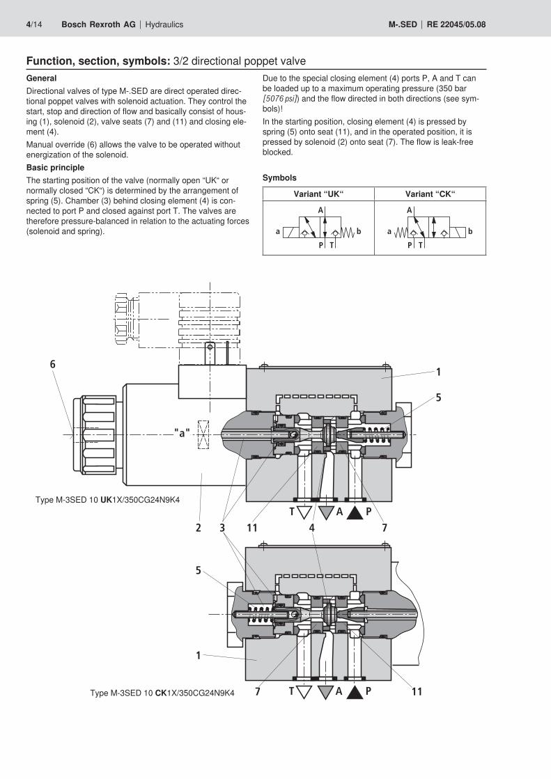
Function, section, symbols: 3/2 directional poppet valveDue to the special closing element (4) ports P, A and T can be loaded up to a maximum operating pressure (350 bar [5076 psi]) and the flow directed in both directions (see sym-bols)!In the starting position, closing element (4) is pressed by spring (5) onto seat (11), and in the operated position, it is pressed by solenoid (2) onto seat (7). The flow is leak-free blocked.
Symbols
Variant “UK“ Variant “CK“
a b
A
P T
a b
A
P T
GeneralDirectional valves of type M-.SED are direct operated direc-tional poppet valves with solenoid actuation. They control the start, stop and direction of flow and basically consist of hous-ing (1), solenoid (2), valve seats (7) and (11) and closing ele-ment (4).Manual override (6) allows the valve to be operated without energization of the solenoid.Basic principleThe starting position of the valve (normally open “UK“ or normally closed “CK“) is determined by the arrangement of spring (5). Chamber (3) behind closing element (4) is con-nected to port P and closed against port T. The valves are therefore pressure-balanced in relation to the actuating forces (solenoid and spring).
Type M-3SED 10 UK1X/350CG24N9K4
Type M-3SED 10 CK1X/350CG24N9K4
T B P A
8
10
„b”
2
61
5
7
49
11
Hydraulics Bosch Rexroth AGRE 22045/05.08 M-.SED 5/14
Function, section, symbols: 4/2 directional poppet valve Attention!
To avoid pressure intensification when single-rod cylin-ders are used, the annulus area of the cylinders must be connected to A.The use of the Plus-1-Plate and the seat arrangement offer the following options:
Variant “D“ Variant “Y“
a b
A
P T
B
a b
A
P T
B
With the help of a sandwich plate, the Plus-1-Plate, under the 3/2 directional poppet valve, the function of a 4/2 direc-tional poppet valve can be realized.
Function of the Plus-1-Plate– Starting position:
The main valve is not operated. Spring (5) holds closing element (4) on seat (11). Port P is closed, and A connected to T. In addition, a pilot line connects A to the large area of control spool (8), which is thus unloaded to the tank. The pressure applied via P now shifts ball (9) onto seat (10). P is now connected to B, and A to T.
– Transitional position: When the main valve is operated, closing element (4) is shifted against spring (5) and pressed onto seat (7). This closes port T, while P, A and B are briefly connected.
– Operated position: P is connected to A. Because the pump pressure acts via A onto the large area of control spool (8), ball (9) is pressed onto seat (12). In this way, B is connected to T, and P to A. Ball (9) in the Plus-1-Plate has a “positive spool overlap“.
Type M-4SED 10 Y1X/350CG24N9K4
Schematic illustration (starting position)
A T B P
T P
A5 7 4 11
9108 12
3/2 direc-tional pop-pet valve
Plus-1-Plate

6/14 Bosch Rexroth AG Hydraulics M-.SED RE 22045/05.08
Technical data (for applications outside these parameters, please consult us!)
When establishing the electrical conection, properly connect the protective earth conductor (PE ).
1) Suitable for NBR and FKM seals2) Suitable only for FKM seals 3) The cleanliness classes specified for components must be
adhered to in hydraulic systems. Effective filtration prevents malfunction and, at the same time, prolongs the service life of components. For the selection of filters, see data sheets RE 50070, RE 50076, RE 50081, RE 50086, RE 50087 and RE 50088.
4) Special voltages on request5) Due to the surface temperatures of solenoid coils, observe
standards ISO 13732-1 and EN 982!
GeneralWeight – 3/2 directional poppet valve kg [lbs] 2.6 [5.7]
– 4/2 directional poppet valve kg [lbs] 3.9 [8.6]
Installation orientation OptionalAmbient temperature range °C [°F] –30 to +50 [–22 to +122] (NBR seals)
–20 to +50 [–4 to +122] (FKM seals)
HydraulicMaximum operating pressure bar [psi] See Performance limit on page 8Maximum flow l/min [US gpm] 40 [10.6]
Hydraulic fluid Mineral oil (HL, HLP) to DIN 51524 1); fast bio-de-gradable hydraulic fluids to VDMA 24568 (see also RE 90221); HETG (rape seed oil) 1); HEPG (polyg-lycols) 2); HEES (synthetic esters) 2); other hydraulic fluids on request
Hydraulic fluid temperature range °C [°F] –30 to +80 [–22 to +176] (NBR seals)–20 to +80 [–4 to +176] (FKM seals)
Viscosity range mm2/s [SUS] 2.8 to 500 [35 to 2320]
Permissible max. degree of contamination of the hydraulic fluid - cleanliness class to ISO 4406 (c)
Class 20/18/15 3)
ElectricalType of voltage DC voltage AC voltageAvailable voltages 4) V 12, 24, 42, 96, 110,
205, 220Only possible via rectifier
(see page 3)Voltage tolerance (nominal voltage) % ±10Power consumption W 30Duty cycle % 100Switching time to ISO 6403 – ON ms 20 to 50
– OFF 5 to 25 (without rectifier)30 to 50 (with rectifier)
Maximum switching frequency 1/h 15000Type of protection to DIN EN 60529 IP 65 with mating connector mounted and lockedMaximum coil temperature 5) °C [°F] 150 [302]

22
20
18
16
14
12
10
8
6
4
2
5 10 15 20 25 30 35 40
2
1
0
[1][0] [2] [3] [4] [5] [10.6]
0
[319]
[0]
[50]
[100]
[150]
[200]
[250]
[300]
[6] [7] [8] [9]
22
20
18
16
14
12
10
8
6
4
2
5 10 15 20 25 30 35 400
[1][0] [2] [3] [4] [5] [10.6]
0
[319]
[0]
[50]
[100]
[150]
[200]
[250]
[300]
[6] [7] [8] [9]
4
3
350
300
250
200
150
100
6 12 18 24 30 36 42
B22
B12 B15 B18 B20
50
0
[1][0] [2] [3] [4] [5] [11]
0
[5076]
[0]
[500]
[1000]
[1500]
[2000]
[2500]
[6] [7] [8] [9] [10]
[3000]
[3500]
[4000]
[4500]
12
10
8
6
4
6 12 18 24 30 36 42
2
0
[1][0] [2] [3] [4] [5] [11]
0
[174]
[0]
[20]
[6] [7] [8] [9] [10]
[40]
[60]
[80]
[100]
[120]
[140]
[160]
Hydraulics Bosch Rexroth AGRE 22045/05.08 M-.SED 7/14
Pres
sure
diff
eren
tial in
bar
[psi
] →
Pres
sure
diff
eren
tial in
bar
[psi
] →
Flow in l/min [US gpm] →Flow in l/min [US gpm] →
Pres
sure
diff
eren
tial in
bar
[psi
] →
Pres
sure
diff
eren
tial in
bar
[psi
] →∆p-qV characteristic curves 3/2 directional poppet valve
Flow in l/min [US gpm] → Flow in l/min [US gpm] →
∆p-qV characteristic curves Check valve insert
∆p-qV characteristic curves Throttle insert
∆p-qV characteristic curves 4/2 directional poppet valve
1 P to A2 A to T
3 A to T P to B
4 B to T P to A
Characteristic curves (measured with HLP46, ϑoil = 40 °C ±5 °C [104 °F ±9 °F])
8/14 Bosch Rexroth AG Hydraulics M-.SED RE 22045/05.08
Performance limit (measured with HLP46, ϑoil = 40 °C ±5 °C [104 °F ±9 °F])
Symbol Remark
Maximum operating pressure in bar [psi] Flow in l/min
[US gpm]P A B T
2-w
ay c
ircui
t UK a b
A
P T With a 2/2-way circuit, port P or T must be plugged by the customer!
350 [5076]
350 [5076]
350 [5076]
40 [10.6]
CK a b
A
P T
350 [5076]
350 [5076]
350 [5076]
40 [10.6]
3-w
ay c
ircui
t UK a b
A
P T
350 [5076]
350 [5076]
350 [5076]
40 [10.6]
CK a b
A
P T
350 [5076]
350 [5076]
350 [5076]
40 [10.6]
4-w
ay c
ircui
t(fl
ow o
nly
poss
ible
in th
e di
-re
ctio
n of
the
arro
w!)
D a b
A
P T
B 3/2 directional valve (sym-bol "UK") in conjunction with Plus-1-Plate: pP ≥ pA ≥ pB ≥ pT
350 [5076]
350 [5076]
350 [5076]
pP/pA/pB
–40 [10.6]
40 [10.6]
Y a b
A
P T
B 3/2 directional valve (sym-bol "CK") in conjunction with Plus-1-Plate: pP ≥ pA ≥ pB ≥ pT
350 [5076]
350 [5076]
350 [5076]
pP/pA/pB
–40 [10.6]
40 [10.6]
Attention!Please observe the general notes below!The performance limit was established when the solenoid had reached the operating temperature, at 10% undervoltage and no precharging of the tank.
Poppet valves can be used according to the symbols and the assigned operating pressures and flows (see Performance limits above). To ensure reliable operation, the following points must strictly be observed:– Poppet valves feature a negative spool overlap, that is, dur-
ing the switching process, a certain amount of leakage oil is produced. However, this process takes place within such a short time so that it is irrelevant in nearly all applications.
– The specified maximum flow must not be exceeded (if re-quired, install throttle insert for limiting the flow, see page 13)!
Plus-1-Plate:– When using the Plus-1-Plate (4/2 directional func-
tion), observe the following lower operating values: pmin = 8 bar [116 psi], qV > 3 l/min [0.8 US gpm].
– Ports P, A, B and T are clearly assigned in accordance with their tasks. They must not be freely interchanged or plugged!
– Port T must always be connected.– Observe the pressure level and pressure distribution!– The fluid may only flow in the direction of the arrow!
General notes
0,01/100[0.0004/4.0]
Rzmax 4
45
63+
1
7,569
A
P
B
TA TB
11
126 7
2.1 2.21.1
748350,5
10
8
96,7
116,4
30 32,5
-0,5
65-0
,5
102,
5
15
max
. 6
15
3 45 5
F1 F2
F3F4
8,5
[1.99] [3.27] (79,5 [3.13]) [2.91]
[Ø0.252]
[Ø0.433]
[2.72]
[0.295]
[0.5
9][3
.81] [Ø
0.23
6]
[1.1
8]
[1.2
8 -0
.019
7]
[2.5
6-0
.019
7 ]
[4.0
4][0
.59]
[0.3
3]
[2.4
8+0.0
394 ]
[Ø1.
77]
Hydraulics Bosch Rexroth AGRE 22045/05.08 M-.SED 9/14
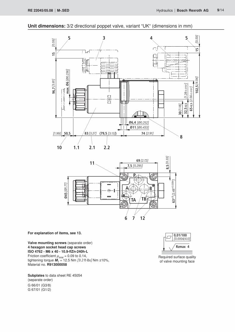
Unit dimensions: 3/2 directional poppet valve, variant “UK“ (dimensions in mm)
Required surface quality of valve mounting face
For explanation of items, see 13.
Valve mounting screws (separate order)4 hexagon socket head cap screws ISO 4762 - M6 x 40 - 10.9-flZn-240h-L Friction coefficient µtotal = 0.09 to 0.14, tightening torque MT = 12.5 Nm [9.2 ft-lbs] Nm ±10%, Material no. R913000058
Subplates to data sheet RE 45054 (separate order)G 66/01 (G3/8) G 67/01 (G1/2)
0,01/100[0.0004/4.0]
Rzmax 4
2.1 2.2 1.2 10
5 4 3 5
8
7 6 12
11
A
P
TA TB
B
20 50,5
102,
515
63+
1
137
96,7
3032,5
-0,5
65-0
,5
15
max
. 6
[1.99][5.39] (133,5 [5.26])
116,4 [Ø0.252]
[Ø0.433]
7,569 [2.72]
[0.295]
[0.5
9][3
.81][Ø
0.23
6]
[1.1
8]
[1.2
8-0
.019
7]
[2.5
6-0
.019
7]
[4.0
4]
[2.4
8+0.0
394 ]
F1 F2
F3F4
[0.5
9]
[0.79]
8,5
[0.3
3]
45
[Ø1.
77]
10/14 Bosch Rexroth AG Hydraulics M-.SED RE 22045/05.08
Unit dimensions: 3/2 directional poppet valve, variant “CK“ (dimensions in mm)
Required surface quality of valve mounting face
For explanation of items, see 13.
Valve mounting screws (separate order)4 hexagon socket head cap screws ISO 4762 - M6 x 40 - 10.9-flZn-240h-L Friction coefficient µtotal = 0.09 to 0.14, tightening torque MT = 12.5 Nm [9.2 ft-lbs] Nm ±10%, Material no. R913000058
Subplates to data sheet RE 45054 (separate order)G 66/01 (G3/8) G 67/01 (G1/2)
0,01/100[0.0004/4.0]
Rzmax 4
2.1 2.2 810
6
91.1
13
5 3 4 5
8050,5
12
48
7483
max
. 6
[1.99] [3.27] (79,5 [3.13]) [2.91]
116,4 [Ø0.252]
[Ø0.433]
96,7
15[0
.59]
[3.8
1] [Ø0.
236]
63+
1
7,569
A
P
B
TA TB
11
136 7
F1 F2
F3F4
[2.72]
[0.295]
[2.4
8+0.0
394 ]
30 32,5
-0,5
65-0
,5
102,
515
[1.1
8]
[1.2
8 -0
.019
7 ]
[2.5
6-0
.019
7]
[4.0
4][0
.59]
[1.8
9]
[3.15]
[0.4
7]
8,5
[0.3
3]
45
[Ø1.
77]
Hydraulics Bosch Rexroth AGRE 22045/05.08 M-.SED 11/14
Unit dimensions: 4/2 directional poppet valve, variant “D“ (dimensions in mm)
Required surface quality of valve mounting face
For explanation of items, see 13.
Valve mounting screws (included in scope of supply)4 hexagon socket head cap screws ISO 4762 - M6 x 90 - 10.9-flZn-240h-L Friction coefficient µtotal = 0.09 to 0.14, tightening torque MA = 12.5 Nm [9.2 ft-lbs] Nm ±10%, Material no. R913000259
Subplates to data sheet RE 45054 (separate order)G 66/01 (G3/8) G 67/01 (G1/2)
0,01/100[0.0004/4.0]
Rzmax 4
2.1 2.2
6
10
9
1.2
80 [3.15]
4 3 5
20 50,5137 [1.99][5.39] (133,5 [5.26])
76 13
11
A
P
TA TB
B
63+
1
7,569 [2.72]
[0.295]
[2.4
8+0.0
394 ]
F1 F2
F3F4
510
2,5
15
3032,5
-0,5
65-0
,5
[1.1
8]
[1.2
8-0
.019
7]
[2.5
6-0
.019
7]
[4.0
4][0
.59]
[0.79]
96,7
15
max
. 6
[0.5
9][3
.81][Ø
0.23
6]
48[1
.89] 11
6,4 [Ø0.252]
[Ø0.433]
12[0
.47]
813
8,5
[0.3
3]
45
[Ø1.
77]
12/14 Bosch Rexroth AG Hydraulics M-.SED RE 22045/05.08
Unit dimensions: 4/2 directional poppet valve, variant “Y“ (dimensions in mm)
Required surface quality of valve mounting face
For explanation of items, see 13.
Valve mounting screws (included in scope of supply)4 hexagon socket head cap screws ISO 4762 - M6 x 90 - 10.9-flZn-240h-L Friction coefficient µtotal = 0.09 to 0.14, tightening torque MT = 12.5 Nm [9.2 ft-lbs] Nm ±10%, Material no. R913000259
Subplates to data sheet RE 45054 (separate order)G 66/01 (G3/8) G 67/01 (G1/2)
Hydraulics Bosch Rexroth AGRE 22045/05.08 M-.SED 13/14
Unit dimensions: Explanation of items
1.1 Solenoid “a“ (for further electrical connections, see RE 08010)
1.2 Solenoid “b“ (for further electrical connections, see RE 08010)
2.1 Dimension for solenoid with concealed manual over-ride “N9“
2.2 Dimension for solenoid without manual override 3 Mating connector without circuitry (separate order,
see page 3)4 Mating connector with circuitry (separate order, see
page 3)5 Space required to remove mating connector6 Nameplate
7 Attention!– On 3/2 directional poppet valves, ports B and TB
are provided as blind countersink.– On 4/2 directional poppet valves, port TB is pro-
vided as blind countersink.8 Identical seal rings for ports A, B and T;
seal ring for port P9 Plus-1-Plate
10 Space required to remove coil11 Porting pattern to ISO 4401-05-04-0-05 and
NFPA T3.5.1 R2-D0512 Valve mounting bores13 Valve mounting screws, see pages 11 and 12
Throttle insert Check valve insertThe use of a throttle insert is required when, due to the giv-en operating conditions, flows can occur during the switch-ing processes, which exceed the performance limit of the valve.
The check valve insert allows free flow from P to A and closes leak-free from A to P.
Examples:– Accumulator operation,– Use as pilot control valve with internal
pilot oil tapping.3/2 directional poppet valveThe throttle insert is to be inserted into port P of the poppet valve.4/2 directional poppet valveThe throttle insert is to be inserted into port P of the Plus-1-Plate. P
3/2 directional poppet valveThe check valve insert is to be inserted in port P of the poppet valve.4/2 directional poppet valveThe check valve insert is to be inserted in port P of the Plus-1-Plate.
P

Bosch Rexroth AG HydraulicsZum Eisengießer 197816 Lohr am Main, Germany Phone +49 (0) 93 52 / 18-0 Fax +49 (0) 93 52 / 18-23 [email protected] www.boschrexroth.de
© This document, as well as the data, specifications and other informa-tion set forth in it, are the exclusive property of Bosch Rexroth AG. It may not be reproduced or given to third parties without its consent.The data specified above only serve to describe the product. No state-ments concerning a certain condition or suitability for a certain applica-tion can be derived from our information. The information given does not release the user from the obligation of own judgment and verifica-tion. It must be remembered that our products are subject to a natural process of wear and aging.
14/14 Bosch Rexroth AG Hydraulics M-.SED RE 22045/05.08
Notes

Bosch Rexroth AG HydraulicsZum Eisengießer 197816 Lohr am Main, Germany Phone +49 (0) 93 52 / 18-0 Fax +49 (0) 93 52 / 18-23 [email protected] www.boschrexroth.de
© This document, as well as the data, specifications and other informa-tion set forth in it, are the exclusive property of Bosch Rexroth AG. It may not be reproduced or given to third parties without its consent.The data specified above only serve to describe the product. No state-ments concerning a certain condition or suitability for a certain applica-tion can be derived from our information. The information given does not release the user from the obligation of own judgment and verifica-tion. It must be remembered that our products are subject to a natural process of wear and aging.
Hydraulics Bosch Rexroth AGRE 22045/05.08 M-.SED 15/14
Notes

Bosch Rexroth AG HydraulicsZum Eisengießer 197816 Lohr am Main, Germany Phone +49 (0) 93 52 / 18-0 Fax +49 (0) 93 52 / 18-23 [email protected] www.boschrexroth.de
© This document, as well as the data, specifications and other informa-tion set forth in it, are the exclusive property of Bosch Rexroth AG. It may not be reproduced or given to third parties without its consent.The data specified above only serve to describe the product. No state-ments concerning a certain condition or suitability for a certain applica-tion can be derived from our information. The information given does not release the user from the obligation of own judgment and verifica-tion. It must be remembered that our products are subject to a natural process of wear and aging.
16/14 Bosch Rexroth AG Hydraulics M-.SED RE 22045/05.08
Notes