323 description of a simulated micro-grid test facility ... cigre paper april...1. introduction...
TRANSCRIPT

323 Description of a Simulated Micro-grid Test Field Facility and Results from
System Testing under Different Load Control Strategies A. Neris*, S. Tselepis, C. Protogeropoulos
Centre for Renewable Energy Sources (CRES) GREECE
Keywords: Micro Grid- Photovoltaic System-Energy Storage-SCADA-Load Control.
1. INTRODUCTION During the last years, considerable interest has grown up for research and development in the field of Dispersed Generation. This term encloses a variety of energy sources with different prime movers, e.g. renewable or co-generation units, connected to the distribution level. A significant portion of this effort concerns the operation of micro-grids in parallel with the mains and in islanding conditions. One of the applications for micro-grids is the electrification of small communities located far from the main grid. In order to investigate operational problems faced in such systems, a simulated micro-grid test facility has been constructed in the framework of EC projects. It is used for the investigation of the optimal way to transform island grids powered by diesel generators, into hybrid ones with the main power contribution coming from distributed PV inverters. Currently, this test facility is being upgraded, through the development of a new SCADA application, the installation of new control and monitoring equipment and finally the connection of the power plant with the public grid. The aim of these activities is the construction of a laboratory that will allow research in a variety of topics related to the autonomous as well as the interconnected operation of the test facility. A description of the main research topics follows hereafter.
• The optimisation of the operation of systems, comprised of local generation, including renewable energy sources and local loads can be achieved with the implementation of an energy management application that will allow maximising the
CIGRE Symposium, Power Systems with Dispersed Generation, Ahtens, Greece, 13-16 April 2005

penetration from renewable sources without sacrificing the security of load supply. Energy management applications require on line information about the system operation. The SCADA system of the test facility constitutes a platform for the development of such applications.
• Renewable energy sources, such as photovoltaic systems, may experience large variances on their output power under variable weather conditions. These variances can cause local problems at the distribution grid regarding voltage regulation and they can also influence the operation of the power system if the penetration from renewable energy sources is large. The use of local energy storage with the appropriate power electronic interface can assist to the compensation of these problems [1]. The micro-grid test facility will be used for research in this direction.
• Power quality is a very broad issue that refers to the electrical interaction between the electricity grid and its customers. Power quality topics that will be examined within the micro-grid test facility concern the interaction of power electronic interfaces for renewable energy sources or storage devices and different types of loads as well as the influence of the power electronic interfaces operation on the voltage quality at the point of coupling with the public grid.
The scope of this paper is to present the structure of the micro-grid test facility, with emphasis on the developed SCADA application. In order to illustrate the capabilities of the test facility, results from experiments for the investigation of the benefits of load control in autonomous island grids are presented and discussed.
2. MICRO-GRID TEST FACILITY DESCRIPTION
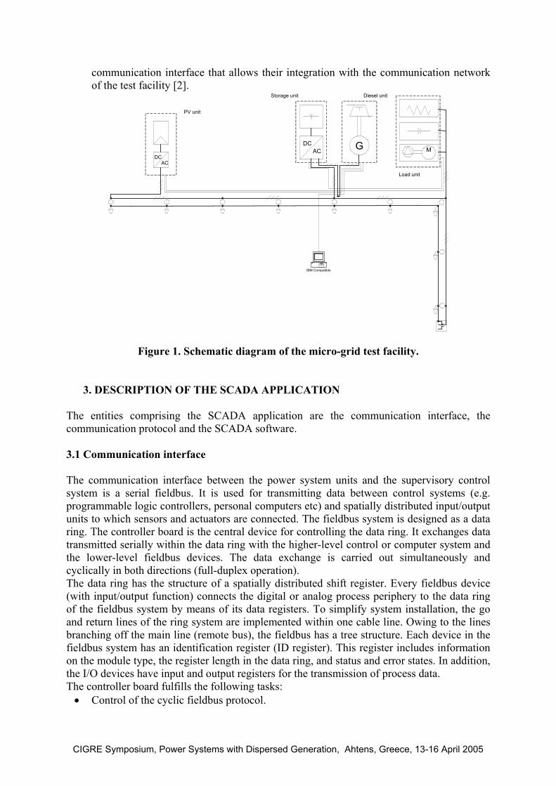
A schematic diagram of the micro-grid test facility is depicted in Figure 1. The units comprising the plant are:
• A 4.4 kWp PV unit connected to the grid through an inverter. The inverter is specifically
designed for grid-connected photovoltaic applications. It regulates the dc voltage for maximum power extraction from the sun. The grid interface of the inverter is equipped with the necessary synchronization and protection functions.
• A 40 kWh battery storage unit connected to the grid through an inverter. The inverter has two modes of operation:
a) Grid-connected mode. In this mode the inverter is synchronised with the voltage produced from the diesel generator. The controllable variables are the active and reactive components of the current injected or absorbed from the inverter. b) Autonomous mode. In this mode the inverter built its own three-phase voltage system. The controllable variables are the frequency and the amplitude of the voltage output. The grid interface of the inverter is equipped with the necessary synchronization and protection functions.
• A 12.5 kVA diesel-generator. The speed regulator of the diesel engine can operate either in isochronous or in droop mode. The first option is used when the diesel-generator regulates the frequency of the grid. The second option is used when the diesel-generator is paralleled with other sources.
• A load unit that includes different type of loads (resistive, capacitive, motors). In this part of the system, a number of load controllers have been installed. These controllers are equipped with an efficient control algorithm that decides when to connect or shed load, based on frequency measurements, in order to match the load to the available generation in autonomous grids. Additionally they are equipped with an appropriate
CIGRE Symposium, Power Systems with Dispersed Generation, Ahtens, Greece, 13-16 April 2005
communication interface that allows their integration with the communication network of the test facility [2].
GDCAC
DCAC
M
IBM Compatible
PV unit
Storage unit Diesel unit
Load unit
Figure 1. Schematic diagram of the micro-grid test facility.
3. DESCRIPTION OF THE SCADA APPLICATION
The entities comprising the SCADA application are the communication interface, the communication protocol and the SCADA software.
3.1 Communication interface The communication interface between the power system units and the supervisory control system is a serial fieldbus. It is used for transmitting data between control systems (e.g. programmable logic controllers, personal computers etc) and spatially distributed input/output units to which sensors and actuators are connected. The fieldbus system is designed as a data ring. The controller board is the central device for controlling the data ring. It exchanges data transmitted serially within the data ring with the higher-level control or computer system and the lower-level fieldbus devices. The data exchange is carried out simultaneously and cyclically in both directions (full-duplex operation). The data ring has the structure of a spatially distributed shift register. Every fieldbus device (with input/output function) connects the digital or analog process periphery to the data ring of the fieldbus system by means of its data registers. To simplify system installation, the go and return lines of the ring system are implemented within one cable line. Owing to the lines branching off the main line (remote bus), the fieldbus has a tree structure. Each device in the fieldbus system has an identification register (ID register). This register includes information on the module type, the register length in the data ring, and status and error states. In addition, the I/O devices have input and output registers for the transmission of process data. The controller board fulfills the following tasks:
• Control of the cyclic fieldbus protocol.
CIGRE Symposium, Power Systems with Dispersed Generation, Ahtens, Greece, 13-16 April 2005
• Transfer of input/output data between fieldbus devices and the control/computer system. • Monitoring of the fieldbus system. • Error Detection (determination of the error type and location; error message to the
control or computer system. • Optical and software-related indications concerning the operating state, errors and the
state of selected inputs/outputs. • Storage of known (defined) bus configurations. 3.2 Communication protocol and SCADA software
The communication protocol used for the processing of the information transmitted through the serial bus system is OPC (OLE for process control). OPC is structured according to the conventional client/server principle. The client, in this case is the SCADA software that runs on the same computer with the server. At its lowest level, the OPC server is an I/O driver that can interchange data with the connected physical device (fieldbus controller board). The client and server exchange data using specified methods. The specifications are provided and published from OPC Foundation [3]. This foundation is an independent nonprofit organisation established by automation industry leaders. The data exchanged are:
• Measurements/analogue data (signals). • Set points sent to the generators and the battery converter. • Binary signals/status data. • Binary control commands to the generators, the battery inverter and the loads of the
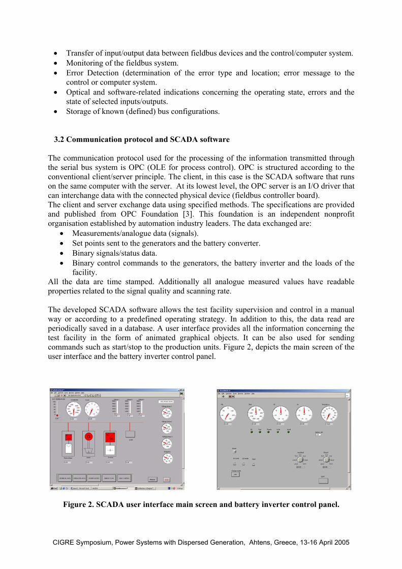
facility. All the data are time stamped. Additionally all analogue measured values have readable properties related to the signal quality and scanning rate. The developed SCADA software allows the test facility supervision and control in a manual way or according to a predefined operating strategy. In addition to this, the data read are periodically saved in a database. A user interface provides all the information concerning the test facility in the form of animated graphical objects. It can be also used for sending commands such as start/stop to the production units. Figure 2, depicts the main screen of the user interface and the battery inverter control panel.
Figure 2. SCADA user interface main screen and battery inverter control panel.
CIGRE Symposium, Power Systems with Dispersed Generation, Ahtens, Greece, 13-16 April 2005
4. LOAD CONTROL EXPERIMENTAL RESULTS In island grids powered by diesel generators and renewable energy sources, it is highly desirable to:
• Maximise the use of renewable energy sources. • Reduce the diesel generators usage. • Run the diesel generator more efficiently. • Provide best use of excess generation. • Provide good power quality.
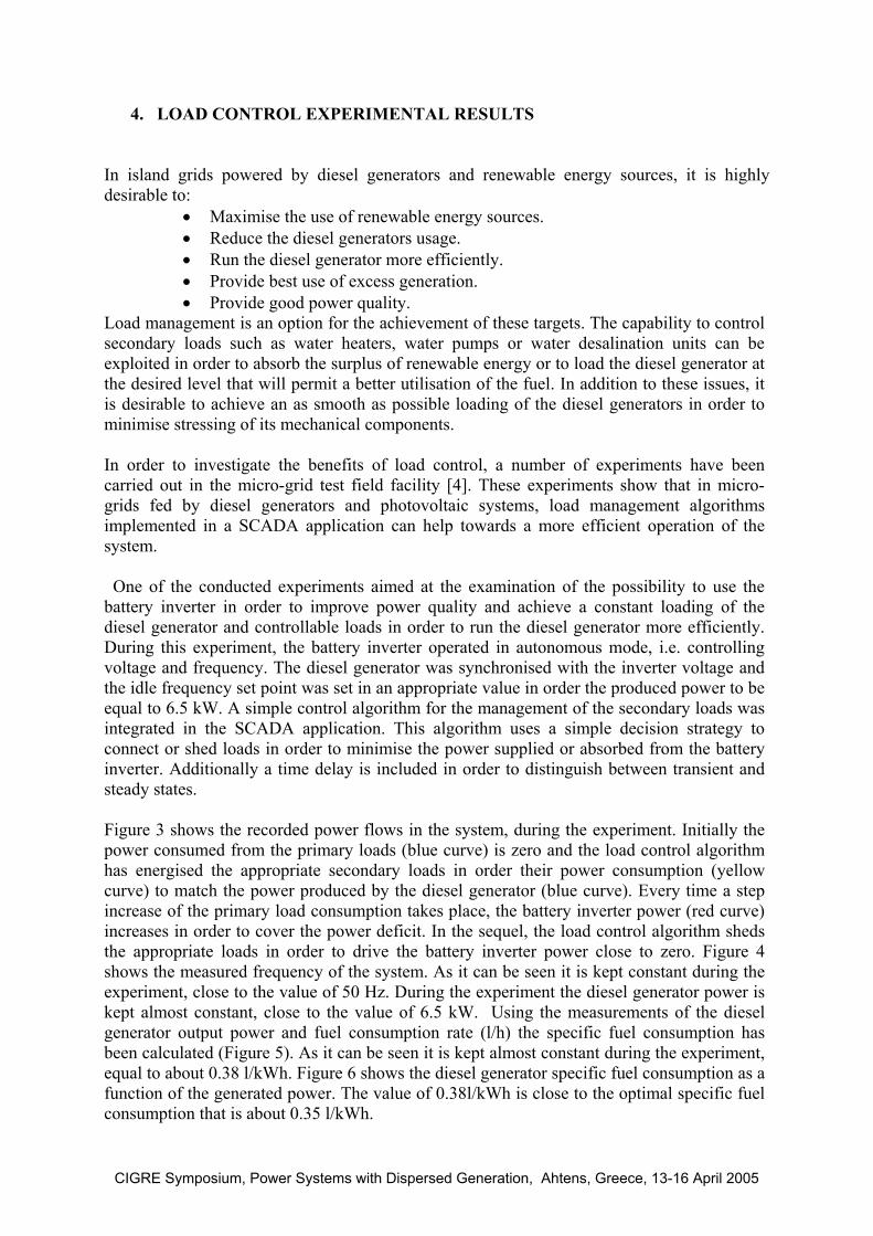
Load management is an option for the achievement of these targets. The capability to control secondary loads such as water heaters, water pumps or water desalination units can be exploited in order to absorb the surplus of renewable energy or to load the diesel generator at the desired level that will permit a better utilisation of the fuel. In addition to these issues, it is desirable to achieve an as smooth as possible loading of the diesel generators in order to minimise stressing of its mechanical components. In order to investigate the benefits of load control, a number of experiments have been carried out in the micro-grid test field facility [4]. These experiments show that in micro-grids fed by diesel generators and photovoltaic systems, load management algorithms implemented in a SCADA application can help towards a more efficient operation of the system. One of the conducted experiments aimed at the examination of the possibility to use the battery inverter in order to improve power quality and achieve a constant loading of the diesel generator and controllable loads in order to run the diesel generator more efficiently. During this experiment, the battery inverter operated in autonomous mode, i.e. controlling voltage and frequency. The diesel generator was synchronised with the inverter voltage and the idle frequency set point was set in an appropriate value in order the produced power to be equal to 6.5 kW. A simple control algorithm for the management of the secondary loads was integrated in the SCADA application. This algorithm uses a simple decision strategy to connect or shed loads in order to minimise the power supplied or absorbed from the battery inverter. Additionally a time delay is included in order to distinguish between transient and steady states. Figure 3 shows the recorded power flows in the system, during the experiment. Initially the power consumed from the primary loads (blue curve) is zero and the load control algorithm has energised the appropriate secondary loads in order their power consumption (yellow curve) to match the power produced by the diesel generator (blue curve). Every time a step increase of the primary load consumption takes place, the battery inverter power (red curve) increases in order to cover the power deficit. In the sequel, the load control algorithm sheds the appropriate loads in order to drive the battery inverter power close to zero. Figure 4 shows the measured frequency of the system. As it can be seen it is kept constant during the experiment, close to the value of 50 Hz. During the experiment the diesel generator power is kept almost constant, close to the value of 6.5 kW. Using the measurements of the diesel generator output power and fuel consumption rate (l/h) the specific fuel consumption has been calculated (Figure 5). As it can be seen it is kept almost constant during the experiment, equal to about 0.38 l/kWh. Figure 6 shows the diesel generator specific fuel consumption as a function of the generated power. The value of 0.38l/kWh is close to the optimal specific fuel consumption that is about 0.35 l/kWh.
CIGRE Symposium, Power Systems with Dispersed Generation, Ahtens, Greece, 13-16 April 2005
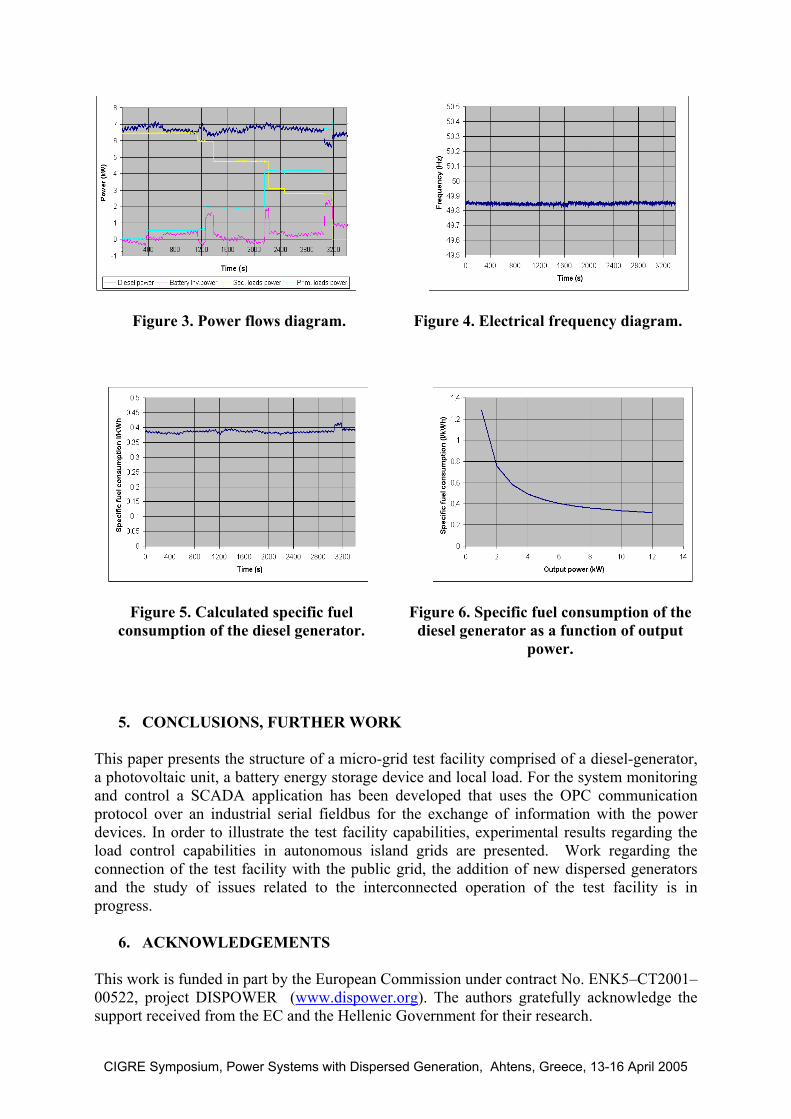
Figure 3. Power flows diagram. Figure 4. Electrical frequency diagram.
Figure 5. Calculated specific fuel consumption of the diesel generator.
Figure 6. Specific fuel consumption of the diesel generator as a function of output
power.
5. CONCLUSIONS, FURTHER WORK
This paper presents the structure of a micro-grid test facility comprised of a diesel-generator, a photovoltaic unit, a battery energy storage device and local load. For the system monitoring and control a SCADA application has been developed that uses the OPC communication protocol over an industrial serial fieldbus for the exchange of information with the power devices. In order to illustrate the test facility capabilities, experimental results regarding the load control capabilities in autonomous island grids are presented. Work regarding the connection of the test facility with the public grid, the addition of new dispersed generators and the study of issues related to the interconnected operation of the test facility is in progress.
6. ACKNOWLEDGEMENTS
This work is funded in part by the European Commission under contract No. ENK5–CT2001–00522, project DISPOWER (www.dispower.org). The authors gratefully acknowledge the support received from the EC and the Hellenic Government for their research.
CIGRE Symposium, Power Systems with Dispersed Generation, Ahtens, Greece, 13-16 April 2005
7. REFERENCES 1. K.C.Kalaitzakis, G.J.Vachtsevanos, On the Control and Stability of Grid Connected
Photovoltaic Sources (IEEE Transactions on Energy Conversion, Vol.2, No.3, December 1987, p. 556-562).
2. I.B.Williamson, R.B.Kemsley, P.Taylor, D.Rolinson, S.Tselepis, A.Neris, Intelligent load control strategies utilising communication capabilities to improve the power quality of inverter based renewable energy power systems, (International Conference RES for Island Tourism and Desalination, Hersonissos, Crete, Greece, May 26-28, 2003).
3. www.opcfoundation.org 4. A. Neris, S.Tselepis, Power quality measurements in mini-grids including
photovoltaic units and battery storage, (2nd European PV-Hybrid and Mini-Grid Conference, Kassel, Germany, September 25-26, 2003, p. 346-351).
SUMMARY
One of the applications for micro-grids is for the electrification of small communities away from the main grid. In order to investigate operational problems faced in such systems, a simulated micro grid test facility has been constructed in the framework of EC projects. It is used for the investigation of the optimal way to transform island grids powered by diesel generators, into hybrid ones with the main power contribution coming from distributed PV inverters. Currently, the test facility is being upgraded, through the development of a new SCADA application; the installation of new control and monitoring equipment, new dispersed generators and finally the connection of the power plant with the public grid. In this paper the structure of the micro grid test facility with emphasis on the SCADA application is described. The SCADA application is based in OPC technology. The communication interface between the power system units and the supervisory control system is an industrial serial bus. In order to illustrate the capabilitities of the test facility, experimental results regarding the benefits of load control in autonomous island grids are provided and discussed.
CIGRE Symposium, Power Systems with Dispersed Generation, Ahtens, Greece, 13-16 April 2005