3.3.2 electrical design criteria - facilities. 3, design standards 3.3 building systems 3.3.2...
TRANSCRIPT

Chap. 3, Design Standards 3.3 Building Systems
3.3.2 Electrical Design Criteria
28 June, 2013 3-112
3.3.2 ELECTRICAL DESIGN CRITERIA
3.3.2.1 General Design Criteria
3.3.2.1.1 Installation Design Requirements
• In atriums or other multi-story open areas, accessibility and maintenance shall be a consideration when
mounting lights.
• Ensure maintenance and accessibility provisions for servicing and replacement of equipment.
• Provide adequate working area around equipment for service.
• There must be permanent access to the roof if any equipment needing service is mounted on the roof.
• Access doors to crawl spaces shall be located as close as possible to electrical equipment under floor.
3.3.2.1.2 Evaluation or Commissioning
• List of items or systems requiring testing, evaluation, verification, or commissioning:
o Commissioning report: The entire emergency systems, UPS systems and lighting control systems
shall fall under the scope of the Commissioning process and be subject to the protocols listed in
the independent Commissioning guidelines.
o Operations and Maintenance Manuals: shall be provided as required by the independent Close-out
Guidelines.
3.3.2.2 Power Distribution System
3.3.2.2.1 Power System Overview
3.3.2.2.1.1 Utilization Voltages
Primary Voltages:
13.27kV, 3 Phase, 3 Wire
Secondary Voltages:
Normal 480Y/277V, 3 Phase, 4 Wire
208Y/120V, 3 Phase, 4 Wire
Emergency/Standby 480Y/277V, 3 Phase, 4 Wire
208Y/120V, 3 Phase, 4 Wire
Branch Circuits:
General Use Receptacles 120V

Chap. 3, Design Standards 3.3 Building Systems
3.3.2 Electrical Design Criteria
28 June, 2013 3-113
Special Purpose Receptacles 208V, 1 phase and 208V, 3 phase
Fluorescent Lighting 277V
Special Purpose Incandescent
Lighting
120V
Motors 1/3 HP and smaller 120V
Motors 1/2 HP and larger 480V, 3 phase
3.3.2.2.1.2 Primary Service
• Information related to available fault current and feeder information is provided on a project by
project basis by Mason Facilities Management Services.
• Required information from the project team includes projected loads as well as the location of
service entrance equipment.
• Information related to the specific feeder(s) to be connected to, manhole(s) to be connected to,
available fault current(s) and related information will be provided by Mason Facilities
Management Services.
3.3.2.2.1.3 Electrical Metering
• Provide digital electric meters for all new buildings.
• Meter Location: Meters shall be located on the substation mains and/or the main service to each
facility and/or the distribution main. The addition of meters on branch distribution equipment will
be determined on a project basis by Facilities Management Services.
• Meter Installation: All metering devices shall have a minimum ¾” conduit with 2 pair 18 AWG
stranded individually and overall shielded cable installed from the new meter location to the main
telephone backboard. All devices shall be interconnected in a series (daisy chain) configuration.
3.3.2.2.1.4 Primary Feeder Equipment and Distribution Equipment
• Manholes and Handholes
o Facilities Management Services will identify connection location(s) and designated
manholes(s) or handhole(s) for each project. Facilities Management Services will also
provide details and fault current information for each manhole or handhole.
3.3.2.2.1.5 Medium Voltage Feeders
• 33% spare capacity shall be included for each feeder. Conduits shall not be more than two-thirds
filled.

Chap. 3, Design Standards 3.3 Building Systems
3.3.2 Electrical Design Criteria
28 June, 2013 3-114
• For every conduit provided for the project, an equal number of spare conduits shall be provided
from the manhole to the Main Electrical Room. Conduits shall be a minimum of 5”. Wire size
shall be a maximum of 500 MCM.
3.3.2.2.1.6 Grounding
• Provide an electrode system consisting of all code required grounding electrodes bonded together
including metal underground water pipes, metal frame of building or structure, concrete encased
electrodes, and ground rods.
• The grounding shall consist of a three ground rods in a tripose arrangement connected with 4/0
AWG bare copper ground conductor under a minimum of 1 foot of cover. The ground rods shall
be copper clad steel rods 3/4” diameter x 10’-0” long with top1’-0” below grade.
• Ground rods shall be located as minimum one at each lightning protection down conductor, three
at the service entrance location spaced at least one rod length from each other and at least the same
distance from other grounding electrodes and at no more than 60 foot intervals around the
perimeter.
• The building main electrical room shall be provided with a connection to the grounding electrode
system for bonding the neutral conductor at the transformer secondary overcurrent protective
device. The grounding electrode system shall also be extended to ground buses located distributed
electrical rooms for supplemental grounding and bonding of separately derived systems.
• A separate connection to the grounding electrode system shall be extended to ground buses located
in the main communication and intermediate distributed communication rooms.
• All underground connections and connections to structural steel shall be welded connections.
Above ground exposed connections will be bolted connections.
• All feeders and branch circuits shall have an insulated equipment grounding conductor.
• Electrical classified, hazardous, areas shall be provided with a supplemental ground bus to ensure
exposed metal surfaces are at an equipotential level.
3.3.2.2.1.7 Medium Voltage Termination
• Conductor terminations may be cold or heat shrink type termination kits rated 15kV, 95kV BIL
with current rating same as the cable. Splice kits are not acceptable.
3.3.2.2.1.8 Power Shut Off Notification
• 14-day written notification is required prior to any power shut down. Written approval will be
given by Facilities Management services including the approved date and time of shut down. This
information is to be included in the General Notes section of the drawings, typically located on
sheet E-000.
3.3.2.2.2 Normal Power Distribution Equipment
3.3.2.2.2.1 Substations

Chap. 3, Design Standards 3.3 Building Systems
3.3.2 Electrical Design Criteria
28 June, 2013 3-115
• Design engineer will provide the final trip setting for the Main Breakers prior to equipment start-
up.
• Buildings and their equipment shall be served by unit substations where applicable as required for
the load. Generally, substations shall be single ended type, and the secondary or building
distribution system voltage shall be as follows:
o 480Y/277 volt 3 phase 4 wire 60 HZ for buildings with large power loads utilizing 277 volt
for most lighting, and small 480 to 120/208 volt transformer for receptacles, lighting and
small equipment loads as required.
o 208Y/120 volt 3 phase 4 wire 60 HZ for buildings with small power loads that can be readily
served by this voltage.
• Substations shall consist of a medium voltage load break primary switch, dry type ventilated
power transformer and main secondary low voltage switchboard.
• Substation shall be exterior or interior as directed by Mason Facilities Management Division.
• Secondary switchboard main breaker will be set to trip on its lowest setting during construction
and will be adjusted to calculated load required set points during commissioning.
• Due to the increasing use of solid state devices for personal computers, data processing units,
electronic ballasts, and variable speed drives in a facility, the building electrical system in a
facility must be designed to accommodate these non-linear loads. Where these loads are
prevalent, the design must include transformers designed for non-linear load applications and over
sizing of distribution panel neutrals by 200% as well as the neutral conductors of the system
feeding these panels.
3.3.2.2.2.2 Primary Feeders
• All primary feeders shall consist of conduit and copper wire.
3.3.2.2.2.3 Secondary Distribution Transformers
• Secondary distribution transformers and all downstream transformers shall be of explosion
resistant, fire-resistant, air insulated, dry type construction, cooled by the natural circulation of
air through the windings. Only copper windings shall be specified.
3.3.2.2.2.4 Distribution and Branch Circuit Panelboards
• Panelboards that are not located in the same room as their distribution breaker shall have a
main breaker provided in the panel. Exceptions may be made for panels located on the same floor
as their distribution breaker, determined on case by case basis.
3.3.2.2.2.5 Variable Frequency Controllers
• See Chapter 4 of the Design Manual.
3.3.2.2.2.6 Secondary Feeders

Chap. 3, Design Standards 3.3 Building Systems
3.3.2 Electrical Design Criteria
28 June, 2013 3-116
• All secondary feeders shall consist of conduit and copper wire.
3.3.2.2.2.7 Branch Circuits
• Ratings and Size: Branch circuits shall be at minimum #12AWG.
• Acceptable Conduit Types:
o Conduit shall be specified as Electrical Metallic Tubing (EMT) or Intermediate Metal Conduit
(IMC).
o Flexible metal conduit (FMC) is acceptable for up to 6 foot max for final terminations to
motor loads and light fixtures.
• Conduit Size and Fill
o A minimum of ¾” conduit shall be specified. A minimum of ½”conduit is acceptable for
distribution to receptacles.
o No more than 9 conductors (3-phase, 3 neutral and 3 ground) shall be installed in a common
conduit.
• Usage
o Branch circuits shall be comprised of like usage. Branch circuits with computer equipment
shall have only computers on the circuit. Printers and computers shall not be placed on the
same circuit. In general, motors and computers shall not be placed on the same circuit.
Branch circuits with computers on them shall be limited to maximum (4) computers per
circuit.
o Electrical wiring system shall be designed and installed with as much flexibility as practical
and reasonable.
o In demolition associated with renovations all wire shall be removed back to the panelboard
and all accessible conduits shall be removed.
o Other branch circuits shall have a maximum of 6-8 receptacles per circuit to allow for future
receptacles.
o Receptacles (and light fixtures) shall be circuited such that the room or area has a diversity of
circuits. For example, all outlets in one office shall not be on the same circuit. The failure of
one circuit should not take down an entire area.
o Corridor outlets shall be on a separate circuit with only other corridor outlets.
• J-boxes for Branch Circuits
o At least one j-box shall be provided for the receptacle branch circuits feeding each room.
Branch circuits shall enter the room, connect to the j-box and then continue to the appropriate
receptacles. If the circuit continues to an adjacent room, the connection shall be j-box to j-
box.

Chap. 3, Design Standards 3.3 Building Systems
3.3.2 Electrical Design Criteria
28 June, 2013 3-117
• Commercial Cooking Systems
o All electrical shunts and other associated shut off devices shall be labeled.
3.3.2.2.2.8 Wiring Devices
• Plate Colors and Labeling
o The preferred device plate is plastic. Plate colors typically are specified by the architect.
White shall be the default color. For receptacles with special power requirements, plate
colors shall match receptacle colors.
o All device plates shall be labeled with originating panel and circuit numbers. The preferred
labeling method is black lettering on clear ½” labeling tape.
• Projects that include pre-wired workstations are also required to have each receptacle labeled with
panel and circuit number. A note shall indicate as such on both the electrical drawings as well as
the furniture plans.
• Receptacle Colors:
o The default receptacle color shall be white.
o For emergency receptacles, receptacle and plate shall be red.
o For UPS receptacles, receptacle and plate shall be orange.
o For receptacles with isolated ground, receptacle shall be white with an orange triangle. No
preference on plate color.
• Receptacle Orientation
o All receptacles shall be orientated with the ground up.
o For receptacles located in wiremold, receptacle orientation shall be specified by the engineer
on the documents. All receptacles included in the wiremold shall face the same direction.
• GFCI
o Along with code required locations, all Janitors Closets shall be provided with GFCI outlets.
3.3.2.2.3 Emergency and Standby Power
3.3.2.2.3.1 Terminology
• At Mason, the term “emergency system” refers to the entire system supported by a generator.
• The Emergency System, as defined by Article 700, is more commonly referred to as the Life
Safety System.
• The Legally Required Standby Systems (Article 701) and the Optional Standby Systems
(Article 702) are more commonly referred to as the Standby System.
Chap. 3, Design Standards 3.3 Building Systems
3.3.2 Electrical Design Criteria
28 June, 2013 3-118
• Regardless of terminology, all code requirements for the generator systems are to be met.
3.3.2.2.3.2 Acceptable Power Sources
• Order of Preference for Sources
o The preferred method of providing emergency (life safety) power to a building is via
generator.
o In cases where it is not physically feasible to include a generator, a central inverter type
battery system is acceptable.
o In cases where a central inverter type battery system is not feasible, individual local batteries
will be permitted.
o For projects in existing buildings, the method being employed in the building shall be
followed unless otherwise directed by Facilities Management Services.
• Generators
o For existing buildings, where a life safety generator is available, all code required life safety
devices shall be fed by the generator.
o Generators shall be sized with a 20 ~ 30% spare capacity.
o Generator Distribution Board: In the cases where one generator feeds multiple transfer
switches, a distribution board with circuit breakers shall be provided.
o Emergency generators rated 50KW or less shall be natural gas fuel (where available at the
site) with propane backup. Fuel tanks shall not be located underground. Propane tanks shall
be furnished by the Owner. Emergency generators rated above 50KW shall be diesel.
Provide a minimum 8-hour operation fuel tank built into the base of the unit wherever
possible.
o Provide load bank for generators to use when cycling for maintenance. At a minimum,
provide a connection for a portable load bank.
o Consider emergency generator exhaust path in relation t make-up air and building openings.
o Provide grounding system for generator per NEC.
o Generator shall provide operational status to the Fire Alarm Annunciator.
• Generator Fuel Storage Requirements
o Fuel for all generators shall be diesel fuel located in a belly tank. Buried fuel tanks are
unacceptable. Fuel tanks shall be able to sustain full load for a minimum of 8 hours. Lab
buildings shall have a minimum of 24 hour fuel capacity at full load.
o Where a fuel tank is located in-doors or in confined spaces, a remote fill apparatus shall be
provided. The remote fill location should be coordinated with Facilities Management

Chap. 3, Design Standards 3.3 Building Systems
3.3.2 Electrical Design Criteria
28 June, 2013 3-119
Services. Where the remote fill is located outside, tamper resistant and vandalism resistant
devices shall be provided.
o Where fuel storage devices are specified with annunciator panels, annunciator panel shall
interface with the University BMS System for status and alarms.
• Generator Communication: All generators, regardless of the usage, shall communicate with the
University EMCS System. Provisions shall be made to have monitoring contacts from the
generator status panel to communicate with the University BMS System for status updates.
• Automatic Transfer Switch: Automatic transfer switches shall be provided for the connection of
generators. At least two ATS shall be provided to support both emergency (life safety) and
standby loads. One ATS may be provided if only emergency (life safety) load is to be supported as
determined by Facilities Management Services. ATS shall be designed by the engineer.
• Commissioning: Generator and transfer switches shall be commissioned.
• Battery Backup
o Battery backup for life safety lights and exit signs may be acceptable in instances where a
generator is not available or not feasible.
o Central inverter systems with battery backup shall be provided when a generator system is not
feasible. Batteries shall provide a minimum of 90 minutes per code. An automatic battery
charging means shall be provided per code.
o Individual battery systems shall be a last resort.
• UPS Systems
o UPS Systems used consist of two types. One type is the large scale, multi-module type that
requires separate space and large scale battery systems. The second type is the small, local,
under the desk type or “shoe box” UPS. This section covers only the large, central type, UPS
systems.
o Acceptable UPS Configurations: UPS systems shall include a UPS module comprised of
solid-state electronics consisting of a rectifier, an inverter and associated controls. UPS
systems may be either the non-redundant or parallel redundant configurations depending on
the application.
o UPS Batteries: Batteries for the UPS system are typically valve regulated lead acid (VRLA)
batteries due to space constraints. Batteries shall provide a minimum of 30 minutes at full
UPS load. Each UPS module shall be provided with the necessary battery strings for that
module. If more than one module is provided, each shall have its own battery strings to
maintain for a minimum of 30 minutes, regardless of the other module(s).
o Maintenance By-pass Provisions: Each module shall be specified with individual maintenance
by-pass provisions to allow for maximum maintainability of the system.
o Distribution: Distribution for large scale UPS systems are typically provided via power
distribution units (PDU) and remote distribution cabinets (RDC). Different manufacturers

Chap. 3, Design Standards 3.3 Building Systems
3.3.2 Electrical Design Criteria
28 June, 2013 3-120
have different names for these units. PDUs and RDCs models with branch circuit monitoring
is preferred, where available.
o Typical Manufacturers: Large UPS system manufacturers include Emerson Liebert and
Powerware.
o UPS, regardless of the usage, shall communicate with the University EMCS System.
3.3.2.2.3.3 Systems on Generator Power
• Required Systems: All buildings shall be provided with a generator. All required systems shall be
provided emergency power (whether life safety, legally required standby or optional standby
power) to meet code requirements.
• Other Systems: The following systems shall be provided generator power on the proper code
branch where available.
o All access control and/or security devices shall be provided with emergency power.
o All building management system (BMS) devices shall be provided with emergency power.
o Elevator(s) shall be provided with generator power in some applications.
o At least (1) emergency outlet shall be provided in each electrical room, mechanical room,
elevator machine room and other machine rooms.
o At least (1) emergency light fixture shall be provided in each electrical room, mechanical
room, elevator machine room and other machine rooms.
o All domestic eater booster pumps.
3.3.2.2.3.4 Roll Up Generators
• Where the building conditions and the Facilities Management Services require roll up generator
provisions, the following shall be met:
o An adequately sized breaker, meant to accommodate the critical loads in a building, shall be
provided within the main switchgear. A separate section with key interlocks can be provided,
or a remote disconnect can be provided to allow for the safe and efficient connections of a
temporary generator. Options on where the breaker is located and how connections are made
will be determined on a project by project basis by Facilities Management Services.
o For New Buildings - Without a Generator: For a new building, where a permanent generator
has not been specified, roll up generator provisions shall be provided, as directed by Mason.
o For New Buildings - With a Life Safety Generator: For a new building, where a permanent
life safety emergency generator has been specified, roll up generator provisions shall be
provided, as directed by Mason.
o For New Buildings - With a Life Safety & Standby Generator: For a new building, where a
permanent generator has been provided for both life safety power and standby power, roll up
generator provisions are not required.

Chap. 3, Design Standards 3.3 Building Systems
3.3.2 Electrical Design Criteria
28 June, 2013 3-121
o For Existing Buildings - Adding a Life Safety Generator: For an existing building, where a
project involves the addition of a life safety emergency generator, roll up generator provisions
should be considered. In buildings where provisions can be included without major
modifications to existing switchgear and excessive cost to the project, roll up provisions shall
be provided. All other buildings shall be reviewed on a case by case basis.
o For Existing Buildings - Adding a Standby Generator: For an existing building, where a
project involves the addition of a stand by generator in addition to a life safety generator or to
replace an existing generator, roll up provisions are not required.
3.3.2.2.3.5 Fire Pumps
• Concrete encased cable or MI cable is acceptable for feeding the fire pump.
• When the fire pump is provided with generator power, a separate ATS shall be specified as per
code.
3.3.2.3 Lighting System Criteria
3.3.2.3.1 Lighting System Overview
• New buildings shall have lighting provided at 277V. Light fixtures specified for new buildings shall
take into account cost, accessibility, ease of maintenance and availability of replacement parts.
Specialty fixtures should be kept to a minimum.
• Existing buildings may have lighting provided at either 120V or 277V depending on the age of the
facility. Light fixtures specified for existing buildings shall match the existing look and feel of the
building. New fixtures being specified shall also take into account cost, accessibility, ease of
maintenance and availability of replacement parts.
3.3.2.3.1.1 Normal Lighting Distribution Equipment
• Branch Circuits:
o Branch circuits shall be at minimum #12AWG.
o Conduit shall be specified as Electrical Metallic Tubing (EMT) or Intermediate Metal Conduit
(IMC).
o Flexible metal conduit (FMC) is acceptable for up to 6 foot max for final terminations to light
fixtures.
• Conduit Size and Fill:
o A minimum of 3/4” conduit shall be specified.
o No more than 7 conductors (3-phase, 3 neutral and 1 ground) shall be installed in a common
conduit.
o 20% spare capacity shall be left on each circuit for future lights.

Chap. 3, Design Standards 3.3 Building Systems
3.3.2 Electrical Design Criteria
28 June, 2013 3-122
• Usage: Light fixtures shall be circuited such that the room or area has a diversity of circuits where
feasible. It is preferred that all lights in one office not be on the same circuit where multiple
circuits exist in the area in order to minimize the failure of one circuit taking down an entire area.
• J-boxes for Branch Circuits: At least one j-box shall be provided for the lighting branch circuits
feeding each room. Branch circuits shall enter the room, connect to the j-box and then continue to
the appropriate light fixtures. If the circuit continues to an adjacent room, the connection shall be
j-box to j-box.
3.3.2.3.1.2 Lighting Fixtures
• Fixtures shall be specified with cost and availability in mind.
• Fixtures shall have standard parts and be easily maintained.
• Cut sheets of all planned fixtures should be submitted with the project plans and specifications.
• Lenses: In general, Classroom, Hall and Corridor fixtures shall have prismatic lenses. In general,
Office and Conference room fixtures shall have parabolic lenses.
• Standard light fixtures are 2-3-, or 4-lamp, 2’x4’ fluorescent lay-in fixtures with electronic ballasts
and T-8 lamps. T-8 lamps shall have low mercury content, a color rendering index of 75 or
greater and a color temperature of 4100k in academic and general buildings. High mercury
content lamps are unacceptable.
• Light fixtures shall be selected to permit the use of lamps that are on State contract, readily
available from multiple manufacturers and are in typical use at the University.
• No lighting fixtures shall be specified for which the manufacturer will require a minimum order
for the purchase of replacements. Non-catalog and custom lighting fixtures are to be economically
justified and avoided whenever possible.
• Ballasts shall be warranted for 60 months from date of manufacture and shall have harmonic
distortion of less than 15%. Ballasts shall be of the parallel lamp connection design such that
lamps remain fully lit if any of the companion lamps fail.
• Mason requires the use of light emitting diode (LED) lighted exit signs with diffused lenses. Only
red lettered exit signs will be used. Exit lights shall be equal to Lithnia Modular xs/sl series.
• Typical locations for occupancy sensors include small rooms such as individual restrooms, one
person offices, and small storage rooms like closets, supply rooms or recycling rooms, areas of
rescue assistance and conference room and classrooms. Wall switches also be provided in
conference rooms and classrooms such that lights may be controlled by switches when space is
occupied.
• Locate light fixture schedule on drawings. Schedule shall contain a description fixture, not simply
a model number.
• Use of fluorescent dimming systems is discouraged. When approved, the ballasts shall have a
dimming range of 100% to 1%.

Chap. 3, Design Standards 3.3 Building Systems
3.3.2 Electrical Design Criteria
28 June, 2013 3-123
• Provide dimming capability for classrooms to allow note taking while viewing a projections
screen.
• Specify standard lamps not requiring special order or premium price. The following illumination
levels are recommended by Mason. Illumination levels referenced are maintained levels measured
at a 30” height from the floor or at an actual work surface and represent an average level for the
area.
Lighting Levels
Area/Room Name Maintained Foot Candles
Offices & Secretarial Areas 30 - 35
Laboratories 30 (Ambient)
75 - 80 (Task + Ambient)
Study Areas & Classrooms 30 - 75
Conference Rooms & Meeting Rooms 30 40
Lecture Hall Auditorium/Multi Purpose 35 - 50
Corridors & Stairwells 5 - 10 (at Floor)
Reception/Lobby, Lounge 25 - 30
Mechanical, Electrical Rooms 20
Telephone & Elevator Machine Rooms 20
Receiving Areas 25
Storage Areas 25
Rest & Locker Rooms 25 ~ 30
Critical work areas such as tissue labs, culture plate
areas, instrument room, etc.
90 - 100 (Task/Ambient)
• Fluorescent fixtures are generally preferred. Use of the more efficient H.I.D. fixtures is
encouraged only where practical indoors. Incandescent lighting may be used only for special
effect architectural lighting or for limited dimming applications.
• Fluorescent fixtures of the static recessed type shall be used for most hung ceiling applications.
They shall be 2’ x 4’, 1’ x 4’, or 2’ x 2’ based on ceiling grid, size of room or area, and
architectural arrangement. Generally lenses shall be plastic injection molded prismatic type of
100% virgin acrylic. In areas requiring low brightness, numerous CRT’s, or similar equipment,
parabolic type louvered fixture shall be used. Commercial fluorescent fixtures shall be used where
applicable for surface or stem mounted fixture shall be metal with hinged shielding lens of 100%
virgin acrylic prismatic type. Industrial type fluorescent fixtures with bulb protection shall be
used in mechanical equipment rooms, storage and receiving areas and similar spaces.
• Stairwells in buildings shall have sufficient fixtures so that loss of one lamp or ballast will not
leave the area dark. Please use wall mounted fixtures in stairwells that can be serviced from a 6’
ladder.
• Lighting fixtures in garages shall be sealed and watertight.
3.3.2.3.1.3 Lighting Power Density
Chap. 3, Design Standards 3.3 Building Systems
3.3.2 Electrical Design Criteria
28 June, 2013 3-124
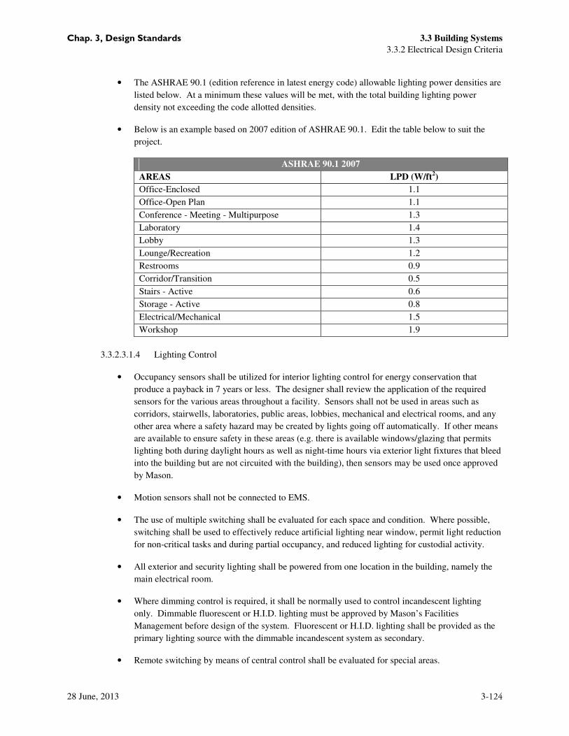
• The ASHRAE 90.1 (edition reference in latest energy code) allowable lighting power densities are
listed below. At a minimum these values will be met, with the total building lighting power
density not exceeding the code allotted densities.
• Below is an example based on 2007 edition of ASHRAE 90.1. Edit the table below to suit the
project.
ASHRAE 90.1 2007
AREAS LPD (W/ft2)
Office-Enclosed 1.1
Office-Open Plan 1.1
Conference - Meeting - Multipurpose 1.3
Laboratory 1.4
Lobby 1.3
Lounge/Recreation 1.2
Restrooms 0.9
Corridor/Transition 0.5
Stairs - Active 0.6
Storage - Active 0.8
Electrical/Mechanical 1.5
Workshop 1.9
3.3.2.3.1.4 Lighting Control
• Occupancy sensors shall be utilized for interior lighting control for energy conservation that
produce a payback in 7 years or less. The designer shall review the application of the required
sensors for the various areas throughout a facility. Sensors shall not be used in areas such as
corridors, stairwells, laboratories, public areas, lobbies, mechanical and electrical rooms, and any
other area where a safety hazard may be created by lights going off automatically. If other means
are available to ensure safety in these areas (e.g. there is available windows/glazing that permits
lighting both during daylight hours as well as night-time hours via exterior light fixtures that bleed
into the building but are not circuited with the building), then sensors may be used once approved
by Mason.
• Motion sensors shall not be connected to EMS.
• The use of multiple switching shall be evaluated for each space and condition. Where possible,
switching shall be used to effectively reduce artificial lighting near window, permit light reduction
for non-critical tasks and during partial occupancy, and reduced lighting for custodial activity.
• All exterior and security lighting shall be powered from one location in the building, namely the
main electrical room.
• Where dimming control is required, it shall be normally used to control incandescent lighting
only. Dimmable fluorescent or H.I.D. lighting must be approved by Mason’s Facilities
Management before design of the system. Fluorescent or H.I.D. lighting shall be provided as the
primary lighting source with the dimmable incandescent system as secondary.
• Remote switching by means of central control shall be evaluated for special areas.

Chap. 3, Design Standards 3.3 Building Systems
3.3.2 Electrical Design Criteria
28 June, 2013 3-125
• Contractor shall provide the initial lighting control setup.
• Daylighting:
o For daylighting to fully recognize energy savings and become a true sustainability strategy,
automatic daylighting controls are needed. These controls switch or dim lighting
automatically and maintain a target light level. The more usable daylight falls on the task
plane, the less electric light is needed.
o Daylight harvesting strategies have been demonstrated to produce 35-40 percent energy
savings in office spaces according to the New Buildings Institute. For this reason, the
ASHRAE Advanced Energy Design Guides and Advanced Buildings Benchmark encourage
daylight harvesting controls.
o For continuous occupied space automatic controls that constantly adjust the electric lighting
in response to the available daylight shall be used. The best type makes use of dimmable
ballasts controlled by photo-sensors operating fluorescent lamps. Past studies have shown
that on/off controls tend to annoy those working in the space and occupants may not bother to
use manual lighting controls to turn off lights when enough daylight is available.
o Fluorescent dimming ballasts allow energy savings of nearly 85 percent at 10 percent lighting.
Energy consumed and light level change is a linear and nearly directly proportional
relationship as lights are dimmed. Energy consumption decreases continuously as the lights
are dimmed with maximum energy savings at minimum illumination.
o Fluorescent dimming ballasts with 0-10V control will be used to dim the lights to within 10
percent.
3.3.2.3.1.5 Emergency Lighting
• Emergency and exit lighting shall be provided in each building to meet IBC and NFPA codes.
These lights shall be connected to buildings emergency power source.
• Emergency lighting, either electric or photoilluminescent, must be posted at each stairwell door
and building exit. SFPC 1011.1.
• Emergency lighting shall be provided as required by code; including toilet areas, outdoors at all
egress doors, mechanical/main electrical room and in laboratory areas.
• Emergency system wiring shall be in separate conduits, and its distribution through separate
panelboards and motor control centers, etc. as required for a complete system to serve exit lights,
safety lighting in corridors and stairwells, in general assembly areas, and mechanical equipment
rooms and electrical rooms for essential loads, for security systems, fire alarm, and as required.
3.3.2.3.1.6 Switching and Dimming
• Switching Requirements
o All switching shall be bi-level (a, b).

Chap. 3, Design Standards 3.3 Building Systems
3.3.2 Electrical Design Criteria
28 June, 2013 3-126
o Location: Switches shall be located on the wall opposite the side of the door swing. Switch
leg “a” shall be the closest switch to the door.
• Dimming
o The dimming standard for classrooms is Lutron Radio Touch. Lecture hall and auditorium
standard is the Lutron Grafik system.
• Back of House Locations
o Back of house locations, including electrical rooms, mechanical rooms, elevator machine
rooms, storage rooms and the like, shall be provided with a digital time switch. As permitted
by Mason.
o The preferred digital time switch is The Watt Stopper model TS-400. Equals may be
submitted for approval.
• Exceptions: Certain exceptions and substitutions may be made on a case by case basis by
Facilities Management Services. For example, color temperature of a bulb may be adjusted to
match existing fixtures in an area. All exceptions will be made at the discretion of Mason.
Cut sheets or documentation shall be provided where necessary in order to approve
substitutions and exceptions.
• General Requirements
o The preferred dimming manufacturer is Lutron.
o The preferred manufacturer for occupancy sensors is WattStopper.
o Incandescent bulbs, even in limited quantity are not energy efficient and should not be
specified.
o Bulbs longer than 4’ are not acceptable.
o U lamps are not acceptable.
o Biax lamps above 42 watts are not acceptable.
3.3.2.4 Documentation
3.3.2.4.1 Standards and Code Requirements
• All equipment shall be UL listed, shall be provided with proper identification related to the UL listing,
as well as appropriate listing documentation.
• All equipment and electrical spaces shall meet the minimum code requirements including all Fairfax
City codes and amendments.
3.3.2.4.2 Code References
• All drawing sets shall include code references to the specific code being applied including
International Building Code (IBC), International Energy Conservation Code (IECC) the Virginia

Chap. 3, Design Standards 3.3 Building Systems
3.3.2 Electrical Design Criteria
28 June, 2013 3-127
Statewide Code, National Electrical Code (NEC) and Fairfax City Code Amendments. This reference
shall be made on the E-000 sheet.
3.3.2.4.3 Single Line (One-Line) Diagram Requirements:
o Single line diagrams shall be of the most accurate and descriptive nature allowed by the available
information. Site surveys and earlier drawings shall be used as references to ensure that the single
line being depicted is as up-to-date as possible.
o Projects that include multiple story buildings, regardless if the project scope includes only one
floor*, shall have a “riser” style single line diagram. The single line shall be broken up into floors
and the equipment, both existing and new, shall be shown on the appropriate floor.
o The basement (or lowest level of the building) shall be shown on the bottom of the sheet. The
roof (or highest level of the building) shall be shown on the top of the sheet. Floor delineations
shall be in the form of horizontal lines labeled with Mason’s recognized floor name.
o Projects that include single story buildings or areas may have a “flow” type single line diagram.
o Projects including multiple electrical rooms on one floor shall have single line diagrams that
indicate the room number of each electrical room the gear is located in for quick reference.
o Exceptions may be made by Facilities Management Services in the case of smaller TI projects
that do not require the installation of major pieces of equipment. In these cases, determined
on a project by project basis, the existing single line may be used and amended as necessary.
• All Single Line Diagram sheets shall include the following information:
o All connected building equipment, including panels, generators, switchboards, utility equipment,
mechanical gear, etc.
o Names, locations and ratings of all gear
o Feeder schedule for equipment included in scope of work
o Feeder schedules that do not fit on the single line, due to the amount of equipment being shown,
shall be located on an adjacent sheet. The single line sheet shall make reference to the adjacent
sheet with the feeder schedule. Sheet notes shall be provided as necessary.
• Single Line Diagram sheet numbering:
o Single line diagrams shall be located in the 700 series sheet numbers, regardless of how many
sheets are in the set.
o Normal single line diagrams shall be first in the series. Emergency single line diagrams shall
come next in the series.
o For smaller projects, single line diagrams may be combined with panel schedules to minimize the
page usage. In such cases, the combined single line / panel schedule sheet shall still be located in
the 700 series sheet numbers.

Chap. 3, Design Standards 3.3 Building Systems
3.3.2 Electrical Design Criteria
28 June, 2013 3-128
3.3.2.4.4 Load Summary
• The load summary can be in the form of panel schedules or a table. The load summary shall include
all equipment loads being fed into the main switchgear. Existing equipment may require metering to
determine connected load.
3.3.2.4.5 Scope of work
• The equipment related to the scope of work of the project shall be highlighted or some other way
indicated as included in the project. All building equipment shall be shown as reference and may be
indicated as such.
3.3.2.4.6 Equipment Support
• Support and anchorage of all equipment and conduit.
• Provide fittings for seismic expansion and deflection.
• Provide vibration isolation and seismic anchorage.
3.3.2.4.7 Schedule Requirements
3.3.2.4.7.1 Panel Schedules
• All electrical drawing sets shall include panel schedules. These sheets shall include any and all
panels affected by the project scope, regardless of whether the gear is directly or indirectly
affected.
• Any panel being referenced by a home run in the floor plans shall have an individual panel
schedule and a load summary.
• Panel schedules shall indicate where the panel is located, especially in the cases of large projects
with several Electrical Rooms.
• Reference boxes should be included on each sheet in the drawing set that includes panel
schedules. The reference box should indicate where on the page each panel schedule is located
for quick reference.
3.3.2.4.7.2 Light Fixture Schedule
• A light fixture schedule shall be provided for all projects and shall be included in the electrical
drawing set. The light fixture schedule shall be in table form including all of the pertinent
information necessary for the sub-contractor. Information should include length, ballast type,
wattage, manufacturer and location. See below example light fixture schedule:

Chap. 3, Design Standards 3.3 Building Systems
3.3.2 Electrical Design Criteria
28 June, 2013 3-129
Type Description Manufacturer
and Catalog
No.
Lamps Input
Watts
Volts Comments
Qty. Description
3.3.2.4.8 Circuiting and Identification Requirements
• Each home run shall indicate the corresponding panel name and the circuit number(s).
• Lighting plans and/or reflected ceiling plans shall show the respective lighting panel in its proper
location in each electrical room to provide clear indication of home run destination.
3.3.2.4.9 Special criteria/requirements
3.3.2.4.9.1 Equipment Naming
Naming Categories
Emergency
EL Emergency-Life Safety (as defined by NEC Article 700)
ER Legally Required Stand by (as defined by NEC Article 701)
E Optional Stand by (as defined by NEC Article 702)
Type
U Unit Substation
DB Distribution Board
G Generator
Voltage
H 480 or 480/277
L 208/120V

Chap. 3, Design Standards 3.3 Building Systems
3.3.2 Electrical Design Criteria
28 June, 2013 3-130
Area
N North
S South
E East
W West
*Segments A, B, C, D are also acceptable
Floor
B Basement
1 First
2 Second
3 Third
R Roof
M Mezzanine
Alpha
A Panel
AA Sub panel to A
*Alpha category is sequential. The second panel follows with B and so on.
• Conventions: See Naming Categories above for the selection options in each category.
o Switchboards/Distribution Boards/Panels Naming Convention
Panels shall be named based on the following criteria –
(Emergency) Type Voltage (Area) Floor Alpha
Example 1: a standard 120/208V, panel located on the south side of the second floor
LS2A
Example 2: a 480V emergency standby distribution board located on the north side of the
second floor
EDBHN2
o ATS Naming Convention
ATS shall be named based on the following criteria –
(Emergency) A Voltage (Area) Floor (Alpha)
Example 1: an emergency stand by 480V ATS in the second floor
EAH2
Example 2: the first of two normal 480V ATS on the roof

Chap. 3, Design Standards 3.3 Building Systems
3.3.2 Electrical Design Criteria
28 June, 2013 3-131
AHBA
o Transformer Naming Convention
Transformers shall be named based on the following criteria–
(Emergency) T (Area) Floor (Alpha)
Example 1: a life safety transformer in the south area of the third floor
ELTS3
Example 2: the first of two normal transformers on the fourth floor
T4A
o New or Renovated Buildings: For new buildings and completely renovated buildings, panels
shall be named in relation to the floor the panel is located on and the type of power the panel
is providing. See Conventions section above for additional information.
o Existing Buildings: For existing buildings, panels shall be named in coordination with
existing panels. If no pattern is evident in the existing building for panel naming. See
Conventions section above for additional information. Verify there is no existing panel
with the same name as the new panel in existing buildings.
o Specialty Areas: For buildings with specialty areas, such as a kitchen that includes dedicated
equipment for that specialty area separate than the base building, naming of the dedicated
equipment shall correspond to the specialty area.
For example, a server room added to an existing building will add a dedicated ATS, generator,
distribution board, transformer and panel. The naming convention for this equipment will
include an S. Coordinate with Facilities Management Services for naming convention for
specialty areas.
3.3.2.4.10 Lighting Floor Plan Fixture Labeling
• On the electrical lighting floor plans and/or reflected ceiling plans, each light fixture shall have the
following information:
o Fixture type – in capital letters
o Circuit Number – including panel and circuit
o Switch leg (where applicable) – in lowercase letters
3.3.2.4.11 Coordination
• Light fixtures shall be coordinated with location of equipment, especially in back of house spaces.
Coordination of light locations shall not be left to the contractor or “with field conditions.”

Chap. 3, Design Standards 3.3 Building Systems
3.3.2 Electrical Design Criteria
28 June, 2013 3-132
3.3.2.4.12 Field Verifications
• Expectations: Where existing building is involved, the engineer is expected to visit the project
site once initiated to confirm the existing conditions, including but not limited to project space,
electrical rooms, existing panels, etc. Drawings shall accurately reflect current existing conditions.
• Requests
o Requests for access to the facility and equipment shall be made through the university Project
Manager. Requests shall include areas for access and a brief overview of the plan for the visit.
o Requests for meter data or to meter equipment shall also be made through the university Project
Manager.
3.3.2.4.13 Electrical Coordination Study
• The electrical design will include a short circuit and coordination study to identify overcurrent
protection devices which will provide a selectively coordinated system for the emergency systems in
the building. The design will also include a preliminary arch flash hazard analysis to identify potential
arc flash hazards and to develop strategies to mitigate the hazards. The study shall be submitted to
Mason for review.
• In order to provide a baseline database for operation and maintenance of the building, the project
specifications will require the following studies to be performed by the installing contractor. All
electrical studies will be performed by a registered professional engineer and submitted for review and
approval by the electrical engineer and Owner prior to releasing any equipment and shall include the
following:
o Short circuit: Study shall be conducted at tall busses in the system. Study shall be performed for
both utility, generator and transition mode. Study shall assume full contribution from all motor
loads. A full report shall be provided showing fault currents in all configurations and associated
X/R ration.
o Coordination: Study circuit: Study shall provide all settings for programmable trip units and
adjustable breakers. Study shall include copies of all TC curves used and graphic and test data
indicating proper coordination.
o Arc Flash: Study shall indicate working distance for all panels. Study shall include all labeling
required per NFPA 70E. Labels will be required in electronic format and installation of labels will
be included as a requirement of the specification.
3.3.2.4.14 Estimated Load Summary
• Use tables below to calculate the normal and standby building loads:

Chap. 3, Design Standards 3.3 Building Systems
3.3.2 Electrical Design Criteria
28 June, 2013 3-133
Building Electrical Load Summary
Loads KW KVA Load Growth SUB-TOTAL @ Demand
KW KVA
Lighting
General Power
Manuf.
Mechanical
Elevator
Other
TOTALS
BLDG SF =
Expansion= W/sf kVA/sf
Total SF =
Standby Power Load Summary
Loads KW KVA Load Growth SUB-TOTAL @ Demand
KW KVA
Emergency
Legally
Required
Optional
Standby
Fire Pump
Elevators
TOTALS
BLDG SF =
W/sf kVA/sf
TI Total SF =
3.3.2.5 Fire Alarm System
• A non-coded digital addressable fire alarm system shall be designed for each existing and new building to
meet the NFPA and local codes. The fire alarm system shall be connected to building’s emergency power
source.
• The preferred system is NOTIFIER.
• Per 2009 Virginia Statewide Fire Prevention Code 908.1 for H-use buildings, install a digital voice fire
alarm system that uses standard smoke detectors and manual pull stations.
• All new construction shall be equipped with fire alarm system that includes a building wide Public
Announcement system. The microphone shall be placed in a locked cabinet in the lobby, fire control room,
or other space accessible to building management and first responders. When an emergency occurs,
building management must have access to the system microphone to make announcements.
• The digital voice fire alarm public announcement system shall be capable of interconnecting with a remote
receiver. The receiver would be used to make building or campus-wide announcements from a central
transmitter. SFPC 907.6
• Fire alarm smoke detectors provide in dorm rooms should be supervisory only.
Chap. 3, Design Standards 3.3 Building Systems
3.3.2 Electrical Design Criteria
28 June, 2013 3-134
• All fire alarm devices shall be provided with copper stranded wire, maximum size #12AWG. All wiring
for fire alarm devices shall be in conduit.
• All system wiring and cable must be in conduit.
• The design documents shall include requirements for demolition and remove the old/un-used system and
system components. Abandoning old, un-used and inactive systems and system components is not allowed.
• Fire detection equipment that is located on a pitched roof must have the appropriate tie-offs and guide rails
to facilitate a safe ascent to and descent from the equipment.
• Mason inspectors will perform system testing prior to performance of specified third party inspection and
testing.
3.3.2.5.1 Fire Alarm Plans:
• A full Fire Alarm System design is required as part of the design documents.
• Plans shall be complete and in accordance with BCOM requirements for submittal/approval.
• Devices powered with 120V (or greater) shall be shown on electrical power floor plans with circuit
designations for coordination.
• Fire alarm devices shall be shown on dedicated Fire Alarm plan and shall not be mixed with power
plans.
• Provide a fire alarm operations matrix; Mason will provide an example matrix upon request.
3.3.2.6 Lightning Protection
• Each building shall be considered individually to determine the necessity for lightning protection. The
building location, height, proximity and height of surrounding facilities, etc. shall be analyzed in
determining the need for this protection. If lightning protection is to be provided, it shall be designed and
specified to comply with NFPA #780 “Lightning Protection Code” and the completed system and its
installation must have U.L. master label.