333233d, electric driver for high pressure airless sprayer …€¦ · electric driver for high...
TRANSCRIPT
333233DEN
Repair-Parts
Electric Driver forHigh Pressure Airless SprayerElectric driver for application of protective coatings. For professional use only.Not approved for use in explosive atmospheres or hazardous locations.
Model 24V016
Important Safety InstructionsRead all warnings and instructions in thismanual. Save these instructions.
2 333233D
ContentsRelated Manuals . . . . . . . . . . . . . . . . . . . . . . . . . 2
Warnings . . . . . . . . . . . . . . . . . . . . . . . . . . . . . . . . . 3Installation . . . . . . . . . . . . . . . . . . . . . . . . . . . . . . . . 5
Power Supply . . . . . . . . . . . . . . . . . . . . . . . . . . . 5Connect Power . . . . . . . . . . . . . . . . . . . . . . . . . . 5Grounding . . . . . . . . . . . . . . . . . . . . . . . . . . . . . . 6Install Vented Oil Cap Before Using Equipment . 7
Setup . . . . . . . . . . . . . . . . . . . . . . . . . . . . . . . . . . . . . 7Pressure Relief Procedure . . . . . . . . . . . . . . . . . . . 7Operation . . . . . . . . . . . . . . . . . . . . . . . . . . . . . . . . . 7Maintenance . . . . . . . . . . . . . . . . . . . . . . . . . . . . . . . 8
Preventative Maintenance Schedule . . . . . . . . . . 8Change the Oil . . . . . . . . . . . . . . . . . . . . . . . . . . 8Check Oil Level . . . . . . . . . . . . . . . . . . . . . . . . . . 8Bearing Pre-Load . . . . . . . . . . . . . . . . . . . . . . . . 8
Troubleshooting . . . . . . . . . . . . . . . . . . . . . . . . . . . . 9Power Saving Mode . . . . . . . . . . . . . . . . . . . . . . 9Error Codes . . . . . . . . . . . . . . . . . . . . . . . . . . . . . 9
Repair . . . . . . . . . . . . . . . . . . . . . . . . . . . . . . . . . . . 12Replace Shaft Bearing Assembly . . . . . . . . . . . 12Replace Fan Fuses . . . . . . . . . . . . . . . . . . . . . . 13Replace Fan Assembly . . . . . . . . . . . . . . . . . . . 13Replace Electronics Cover . . . . . . . . . . . . . . . . 15Repair Token Cable . . . . . . . . . . . . . . . . . . . . . . 18Software Update Procedure . . . . . . . . . . . . . . . 19
Parts . . . . . . . . . . . . . . . . . . . . . . . . . . . . . . . . . . . . 20Electric Driver . . . . . . . . . . . . . . . . . . . . . . . . . . 20Parts List - Electric Driver (24V016) . . . . . . . . . 21Mounting Hole Pattern . . . . . . . . . . . . . . . . . . . . 22
Wiring Diagram . . . . . . . . . . . . . . . . . . . . . . . . . . . . 23Dimensions . . . . . . . . . . . . . . . . . . . . . . . . . . . . . . . 24Technical Data . . . . . . . . . . . . . . . . . . . . . . . . . . . . 25Graco Standard Warranty . . . . . . . . . . . . . . . . . . . 26
Related ManualsManuals are available at www.graco.com.
Component manuals in English:
333208 Electric High Pressure Sprayer Manual
Warnings
333233D 3
WarningsThe following warnings are for the setup, use, grounding, maintenance, and repair of this equipment. The exclama-tion point symbol alerts you to a general warning and the hazard symbols refer to procedure-specific risks. Whenthese symbols appear in the body of this manual or on warning labels, refer back to these Warnings. Product-specifichazard symbols and warnings not covered in this section may appear throughout the body of this manual whereapplicable.
WARNINGELECTRIC SHOCK HAZARDThis equipment must be grounded. Improper grounding, setup, or usage of the system can cause electricshock.• Turn off and disconnect power at main switch before disconnecting any cables and before servicing
or installing equipment.• Connect only to grounded power source.• All electrical wiring must be done by a qualified electrician and comply with all local codes and
regulations.
FIRE AND EXPLOSION HAZARDFlammable fumes, such as solvent and paint fumes, in work area can ignite or explode. To help preventfire and explosion:• Use equipment only in well ventilated area.• Eliminate all ignition sources; such as pilot lights, cigarettes, portable electric lamps, and plastic drop
cloths (potential static arc).• Keep work area free of debris, including solvent, rags and gasoline.• Do not plug or unplug power cords, or turn power or light switches on or off when flammable fumes
are present.• Ground all equipment in the work area. See Grounding instructions.• Use only grounded hoses.• Hold gun firmly to side of grounded pail when triggering into pail. Do not use pail liners unless they
are antistatic or conductive.• Stop operation immediately if static sparking occurs or you feel a shock. Do not use equipment
until you identify and correct the problem.• Keep a working fire extinguisher in the work area.
Warnings
4 333233D
EQUIPMENT MISUSE HAZARDMisuse can cause death or serious injury.• Do not operate the unit when fatigued or under the influence of drugs or alcohol.• Do not exceed the maximum working pressure or temperature rating of the lowest rated system compo-
nent. See Technical Data in all equipment manuals.• Use fluids and solvents that are compatible with equipment wetted parts. See Technical Data in all equip-
ment manuals. Read fluid and solvent manufacturer’s warnings. For complete information about yourmaterial, request MSDS from distributor or retailer.
• Do not leave the work area while equipment is energized or under pressure.• Turn off all equipment and follow the Pressure Relief Procedure when equipment is not in use.• Check equipment daily. Repair or replace worn or damaged parts immediately with genuine manufac-
turer’s replacement parts only.• Do not alter or modify equipment. Alterations or modifications may void agency approvals and create
safety hazards.• Make sure all equipment is rated and approved for the environment in which you are using it.• Use equipment only for its intended purpose. Call your distributor for information.• Route hoses and cables away from traffic areas, sharp edges, moving parts, and hot surfaces.• Do not kink or over bend hoses or use hoses to pull equipment.• Keep children and animals away from work area.• Comply with all applicable safety regulations.
MOVING PARTS HAZARDMoving parts can pinch, cut or amputate fingers and other body parts.• Keep clear of moving parts.• Do not operate equipment with protective guards or covers removed.• Pressurized equipment can start without warning. Before checking, moving, or servicing equipment, follow
the Pressure Relief Procedure and disconnect all power sources.
PERSONAL PROTECTIVE EQUIPMENTWear appropriate protective equipment when in the work area to help prevent serious injury, including eye injury,hearing loss, inhalation of toxic fumes, and burns. This protective equipment includes but is not limited to:• Protective eyewear, and hearing protection.• Respirators, protective clothing, and gloves as recommended by the fluid and solvent manufacturer.
WARNING
Installation
333233D 5
Installation
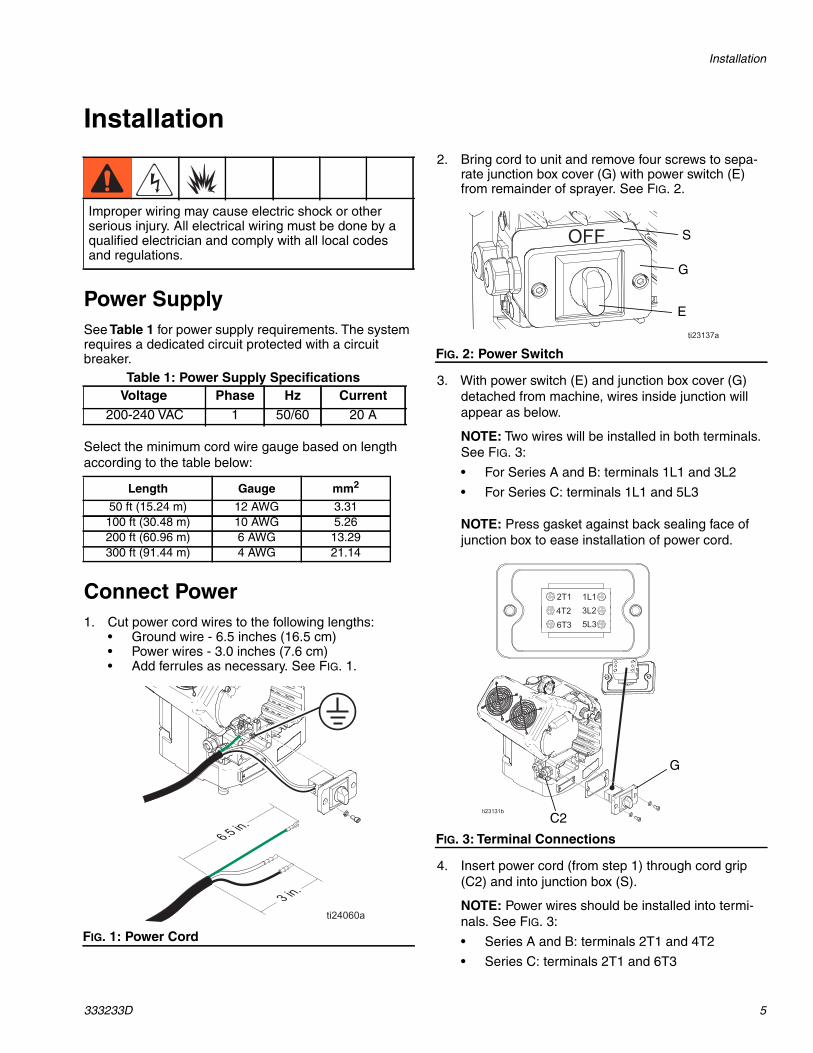
Power SupplySee Table 1 for power supply requirements. The systemrequires a dedicated circuit protected with a circuitbreaker.
Select the minimum cord wire gauge based on lengthaccording to the table below:
Connect Power1. Cut power cord wires to the following lengths:
• Ground wire - 6.5 inches (16.5 cm)• Power wires - 3.0 inches (7.6 cm)• Add ferrules as necessary. See FIG. 1.
2. Bring cord to unit and remove four screws to sepa-rate junction box cover (G) with power switch (E)from remainder of sprayer. See FIG. 2.
3. With power switch (E) and junction box cover (G)detached from machine, wires inside junction willappear as below.
NOTE: Two wires will be installed in both terminals.See FIG. 3:
• For Series A and B: terminals 1L1 and 3L2
• For Series C: terminals 1L1 and 5L3
NOTE: Press gasket against back sealing face ofjunction box to ease installation of power cord.
4. Insert power cord (from step 1) through cord grip(C2) and into junction box (S).
NOTE: Power wires should be installed into termi-nals. See FIG. 3:
• Series A and B: terminals 2T1 and 4T2
• Series C: terminals 2T1 and 6T3
Improper wiring may cause electric shock or otherserious injury. All electrical wiring must be done by aqualified electrician and comply with all local codesand regulations.
Table 1: Power Supply SpecificationsVoltage Phase Hz Current
200-240 VAC 1 50/60 20 A
Length Gauge mm2
50 ft (15.24 m) 12 AWG 3.31100 ft (30.48 m) 10 AWG 5.26200 ft (60.96 m) 6 AWG 13.29300 ft (91.44 m) 4 AWG 21.14
FIG. 1: Power CordGROUNDPOWER
FIG. 2: Power Switch
FIG. 3: Terminal Connections
E
G
S
C2
G
Installation
6 333233D
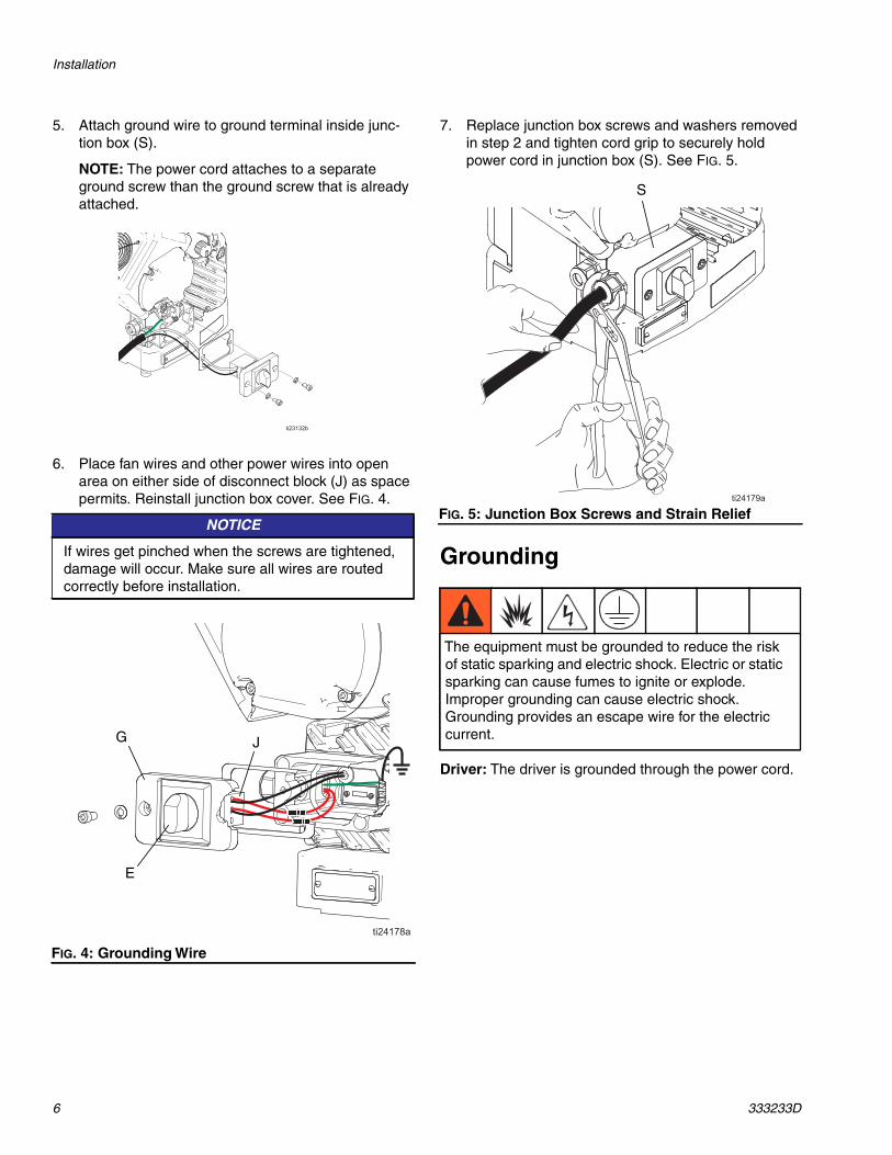
5. Attach ground wire to ground terminal inside junc-tion box (S).
NOTE: The power cord attaches to a separateground screw than the ground screw that is alreadyattached.
6. Place fan wires and other power wires into openarea on either side of disconnect block (J) as spacepermits. Reinstall junction box cover. See FIG. 4.
7. Replace junction box screws and washers removedin step 2 and tighten cord grip to securely holdpower cord in junction box (S). See FIG. 5.
Grounding
Driver: The driver is grounded through the power cord.
NOTICE
If wires get pinched when the screws are tightened,damage will occur. Make sure all wires are routedcorrectly before installation.
FIG. 4: Grounding Wire
G J
E
FIG. 5: Junction Box Screws and Strain Relief
The equipment must be grounded to reduce the riskof static sparking and electric shock. Electric or staticsparking can cause fumes to ignite or explode.Improper grounding can cause electric shock.Grounding provides an escape wire for the electriccurrent.
S
Setup
333233D 7
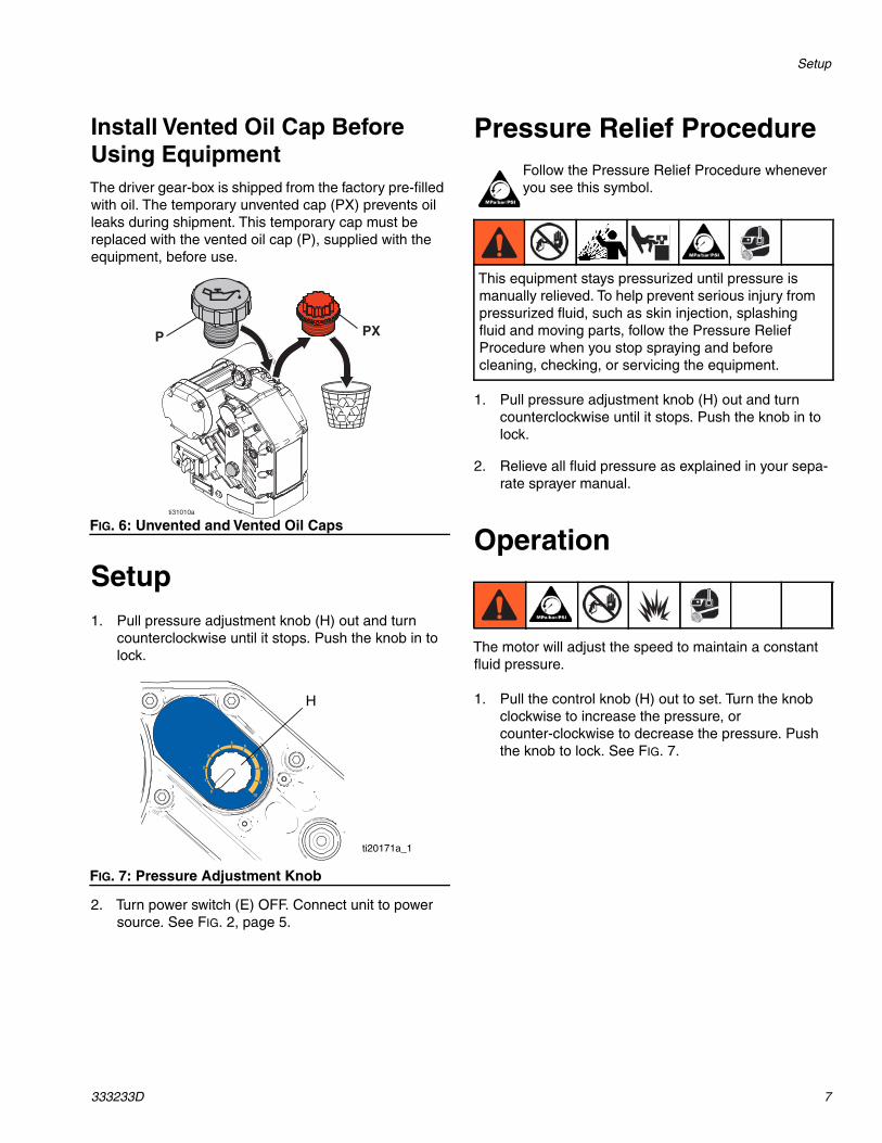
Install Vented Oil Cap BeforeUsing EquipmentThe driver gear-box is shipped from the factory pre-filledwith oil. The temporary unvented cap (PX) prevents oilleaks during shipment. This temporary cap must bereplaced with the vented oil cap (P), supplied with theequipment, before use.
Setup1. Pull pressure adjustment knob (H) out and turn
counterclockwise until it stops. Push the knob in tolock.
2. Turn power switch (E) OFF. Connect unit to powersource. See FIG. 2, page 5.
Pressure Relief ProcedureFollow the Pressure Relief Procedure wheneveryou see this symbol.
1. Pull pressure adjustment knob (H) out and turncounterclockwise until it stops. Push the knob in tolock.
2. Relieve all fluid pressure as explained in your sepa-rate sprayer manual.
Operation
The motor will adjust the speed to maintain a constantfluid pressure.
1. Pull the control knob (H) out to set. Turn the knobclockwise to increase the pressure, orcounter-clockwise to decrease the pressure. Pushthe knob to lock. See FIG. 7.
FIG. 6: Unvented and Vented Oil Caps
FIG. 7: Pressure Adjustment Knob
PXP
ti31010a
H
ti20171a_1
This equipment stays pressurized until pressure ismanually relieved. To help prevent serious injury frompressurized fluid, such as skin injection, splashingfluid and moving parts, follow the Pressure ReliefProcedure when you stop spraying and beforecleaning, checking, or servicing the equipment.
Maintenance
8 333233D
Maintenance
Preventative MaintenanceSchedule
The operating conditions of your particular systemdetermine how often maintenance is required. Establisha preventative maintenance schedule by recording whenand what kind of maintenance is needed, and thendetermine a regular schedule for checking your system.
Change the OilNOTE: Change the oil after a break-in period of 200,000to 300,000 cycles. After the break-in period, change theoil once per year.
1. Place a minimum 2 quart (1.9 liter) container underthe oil drain port. Remove the oil drain plug (15).Allow all oil to drain from the driver.
2. Reinstall the oil drain plug (15). Torque to 18-23 ft-lb(25-30 N•m).
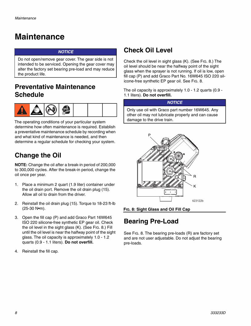
3. Open the fill cap (P) and add Graco Part 16W645ISO 220 silicone-free synthetic EP gear oil. Checkthe oil level in the sight glass (K). (See FIG. 8.) Filluntil the oil level is near the halfway point of the sightglass. The oil capacity is approximately 1.0 - 1.2quarts (0.9 - 1.1 liters). Do not overfill.
4. Reinstall the fill cap.
Check Oil Level
Check the oil level in sight glass (K). (See FIG. 8.) Theoil level should be near the halfway point of the sightglass when the sprayer is not running. If oil is low, openfill cap (P) and add Graco Part No. 16W645 ISO 220 sil-icone-free synthetic EP gear oil. See FIG. 8.
The oil capacity is approximately 1.0 - 1.2 quarts (0.9 -1.1 liters). Do not overfill.
Bearing Pre-Load
See FIG. 8. The bearing pre-loads (R) are factory setand are not user adjustable. Do not adjust the bearingpre-loads.
NOTICE
Do not open/remove gear cover. The gear side is notintended to be serviced. Opening the gear cover mayalter the factory set bearing pre-load and may reducethe product life.
NOTICE
Only use oil with Graco part number 16W645. Anyother oil may not lubricate properly and can causedamage to the drive train.
FIG. 8: Sight Glass and Oil Fill Cap
P
K
R
Troubleshooting
333233D 9
Troubleshooting
Power Saving ModeWhen fast blinking is displayed, the sprayer has enteredPower Saving Mode mode. When the sprayer is on andpressurized but the pump has not moved any material in30 minutes, the sprayer will enter Power Saving Modeand will only control up to 75% of the maximum pressure.
Power Saving Mode will be exited when:
• Material starts to dispense and causes the pump tomove, OR
• The pressure knob is adjusted, OR
• Power is cycled OFF and ON
Error CodesError codes can take two forms:
Alarm: alerts you to the alarm cause and shuts downthe pump.
Deviation: alerts you to the problem, but pump maycontinue to run past the set limits until the system’sabsolute limits are reached.
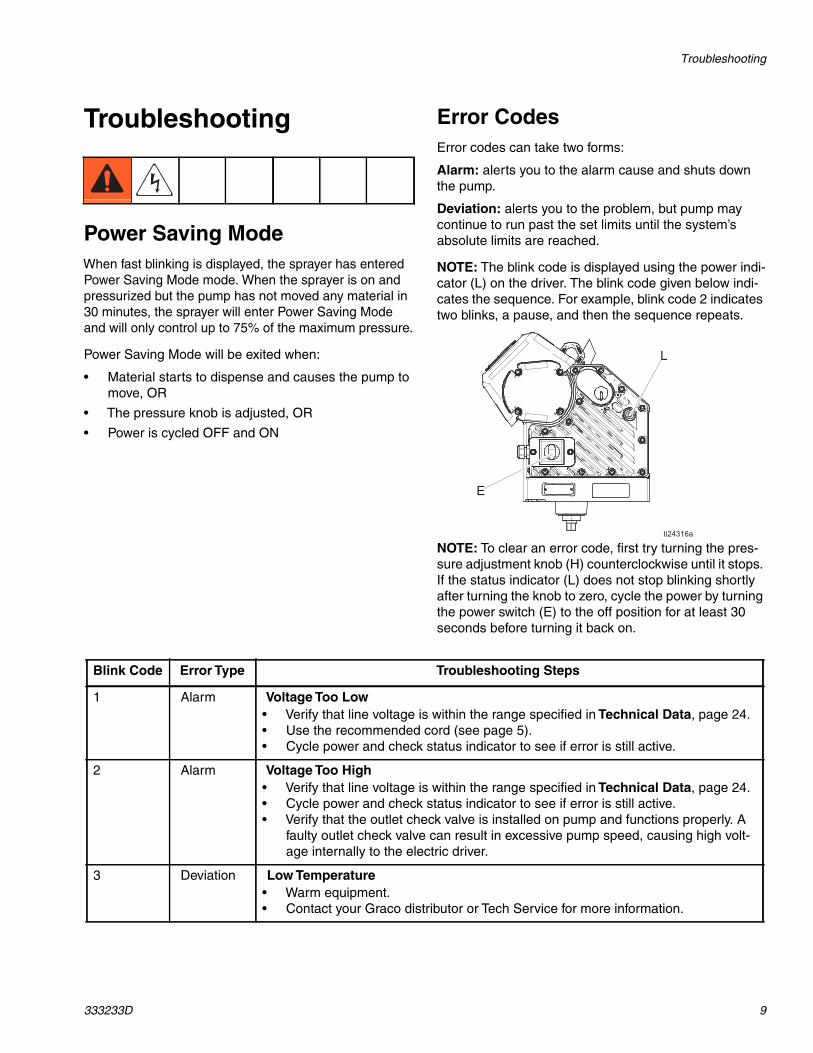
NOTE: The blink code is displayed using the power indi-cator (L) on the driver. The blink code given below indi-cates the sequence. For example, blink code 2 indicatestwo blinks, a pause, and then the sequence repeats.
NOTE: To clear an error code, first try turning the pres-sure adjustment knob (H) counterclockwise until it stops.If the status indicator (L) does not stop blinking shortlyafter turning the knob to zero, cycle the power by turningthe power switch (E) to the off position for at least 30seconds before turning it back on.
Blink Code Error Type Troubleshooting Steps
1 Alarm Voltage Too Low• Verify that line voltage is within the range specified in Technical Data, page 24.• Use the recommended cord (see page 5).• Cycle power and check status indicator to see if error is still active.
2 Alarm Voltage Too High• Verify that line voltage is within the range specified in Technical Data, page 24.• Cycle power and check status indicator to see if error is still active.• Verify that the outlet check valve is installed on pump and functions properly. A
faulty outlet check valve can result in excessive pump speed, causing high volt-age internally to the electric driver.
3 Deviation Low Temperature• Warm equipment.• Contact your Graco distributor or Tech Service for more information.
Troubleshooting
10 333233D
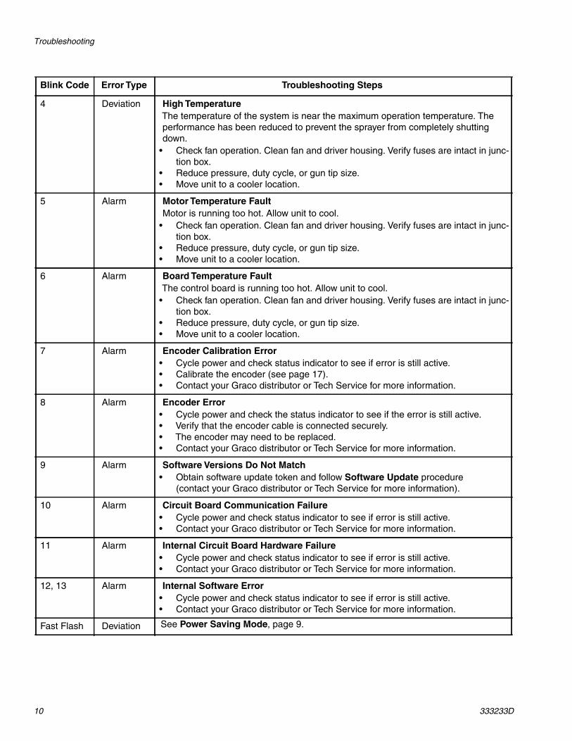
4 Deviation High TemperatureThe temperature of the system is near the maximum operation temperature. Theperformance has been reduced to prevent the sprayer from completely shuttingdown.
• Check fan operation. Clean fan and driver housing. Verify fuses are intact in junc-tion box.
• Reduce pressure, duty cycle, or gun tip size.• Move unit to a cooler location.
5 Alarm Motor Temperature FaultMotor is running too hot. Allow unit to cool.
• Check fan operation. Clean fan and driver housing. Verify fuses are intact in junc-tion box.
• Reduce pressure, duty cycle, or gun tip size.• Move unit to a cooler location.
6 Alarm Board Temperature FaultThe control board is running too hot. Allow unit to cool.
• Check fan operation. Clean fan and driver housing. Verify fuses are intact in junc-tion box.
• Reduce pressure, duty cycle, or gun tip size.• Move unit to a cooler location.
7 Alarm Encoder Calibration Error• Cycle power and check status indicator to see if error is still active.• Calibrate the encoder (see page 17).• Contact your Graco distributor or Tech Service for more information.
8 Alarm Encoder Error• Cycle power and check the status indicator to see if the error is still active.• Verify that the encoder cable is connected securely.• The encoder may need to be replaced.• Contact your Graco distributor or Tech Service for more information.
9 Alarm Software Versions Do Not Match• Obtain software update token and follow Software Update procedure
(contact your Graco distributor or Tech Service for more information).
10 Alarm Circuit Board Communication Failure• Cycle power and check status indicator to see if error is still active.• Contact your Graco distributor or Tech Service for more information.
11 Alarm Internal Circuit Board Hardware Failure• Cycle power and check status indicator to see if error is still active.• Contact your Graco distributor or Tech Service for more information.
12, 13 Alarm Internal Software Error• Cycle power and check status indicator to see if error is still active.• Contact your Graco distributor or Tech Service for more information.
Fast Flash Deviation See Power Saving Mode, page 9.
Blink Code Error Type Troubleshooting Steps
Troubleshooting
333233D 11
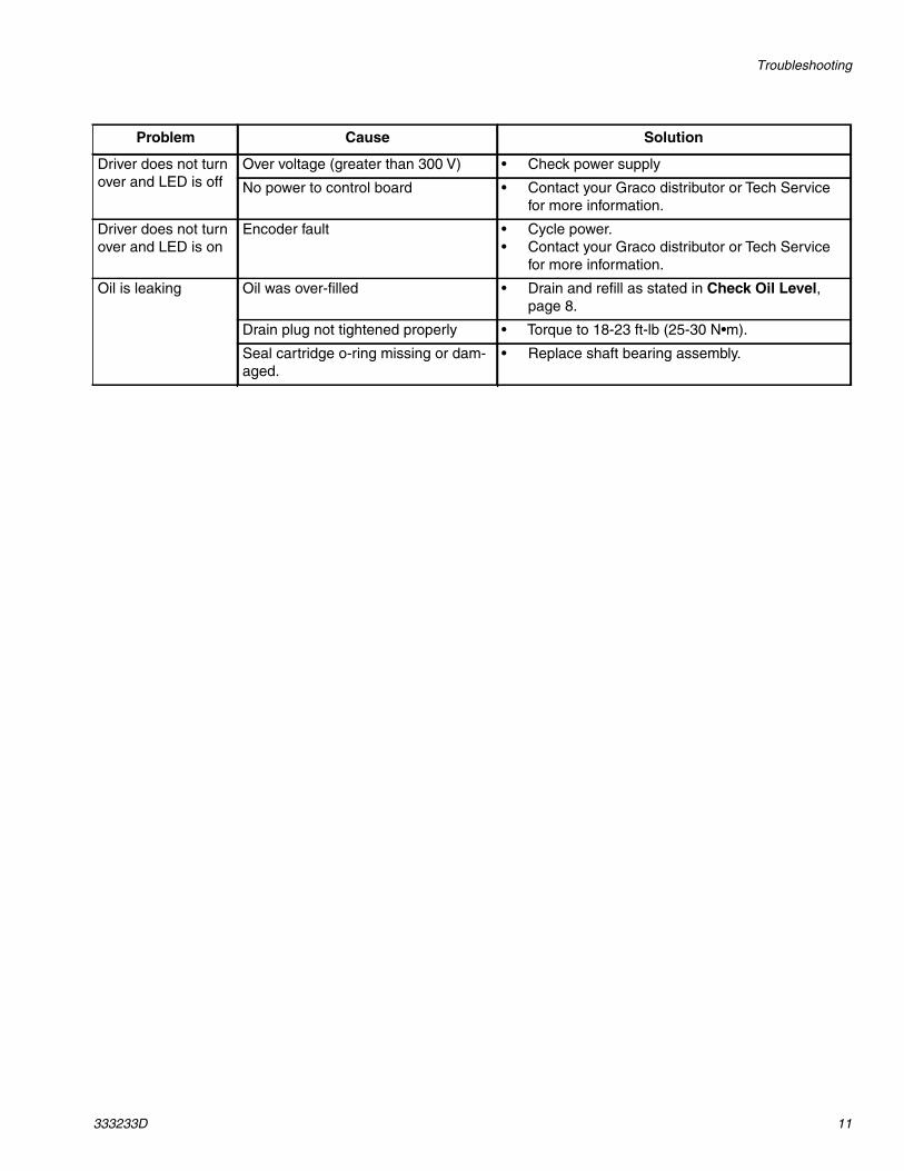
Problem Cause Solution
Driver does not turnover and LED is off
Over voltage (greater than 300 V) • Check power supply
No power to control board • Contact your Graco distributor or Tech Servicefor more information.
Driver does not turnover and LED is on
Encoder fault • Cycle power.• Contact your Graco distributor or Tech Service
for more information.
Oil is leaking Oil was over-filled • Drain and refill as stated in Check Oil Level,page 8.
Drain plug not tightened properly • Torque to 18-23 ft-lb (25-30 N•m).
Seal cartridge o-ring missing or dam-aged.
• Replace shaft bearing assembly.
Repair
12 333233D
Repair
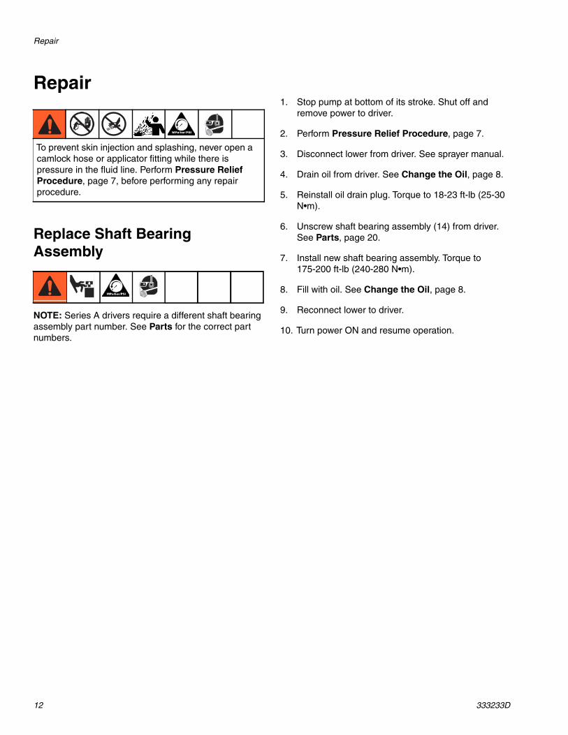
Replace Shaft BearingAssembly
NOTE: Series A drivers require a different shaft bearingassembly part number. See Parts for the correct partnumbers.
1. Stop pump at bottom of its stroke. Shut off andremove power to driver.
2. Perform Pressure Relief Procedure, page 7.
3. Disconnect lower from driver. See sprayer manual.
4. Drain oil from driver. See Change the Oil, page 8.
5. Reinstall oil drain plug. Torque to 18-23 ft-lb (25-30N•m).
6. Unscrew shaft bearing assembly (14) from driver.See Parts, page 20.
7. Install new shaft bearing assembly. Torque to175-200 ft-lb (240-280 N•m).
8. Fill with oil. See Change the Oil, page 8.
9. Reconnect lower to driver.
10. Turn power ON and resume operation.
To prevent skin injection and splashing, never open acamlock hose or applicator fitting while there ispressure in the fluid line. Perform Pressure ReliefProcedure, page 7, before performing any repairprocedure.
Repair
333233D 13
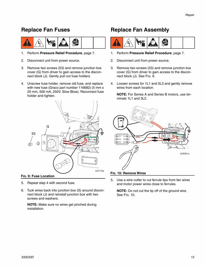
Replace Fan Fuses
1. Perform Pressure Relief Procedure, page 7.
2. Disconnect unit from power source.
3. Remove two screws (53) and remove junction boxcover (G) from driver to gain access to the discon-nect block (J). Gently pull out fuse holders.
4. Unscrew fuse holder, remove old fuse, and replacewith new fuse (Graco part number 116682) (5 mm x20 mm, 500 mA, 250V, Slow Blow). Reconnect fuseholder and tighten.
5. Repeat step 4 with second fuse.
6. Tuck wires back into junction box (S) around discon-nect block (J) and reinstall junction box with twoscrews and washers.
NOTE: Make sure no wires get pinched duringinstallation.
Replace Fan Assembly
1. Perform Pressure Relief Procedure, page 7.
2. Disconnect unit from power source.
3. Remove two screws (53) and remove junction boxcover (G) from driver to gain access to the discon-nect block (J). See FIG. 9.
4. Loosen screws for 1L1 and 5L3 and gently removewires from each location.
NOTE: For Series A and Series B motors, use ter-minals 1L1 and 3L2.
5. Use a wire cutter to cut ferrule tips from fan wiresand motor power wires close to ferrules.
NOTE: Do not cut the tip off of the ground wire.See FIG. 10.
FIG. 9: Fuse Location
53
G J
FIG. 10: Remove Wires
Repair
14 333233D
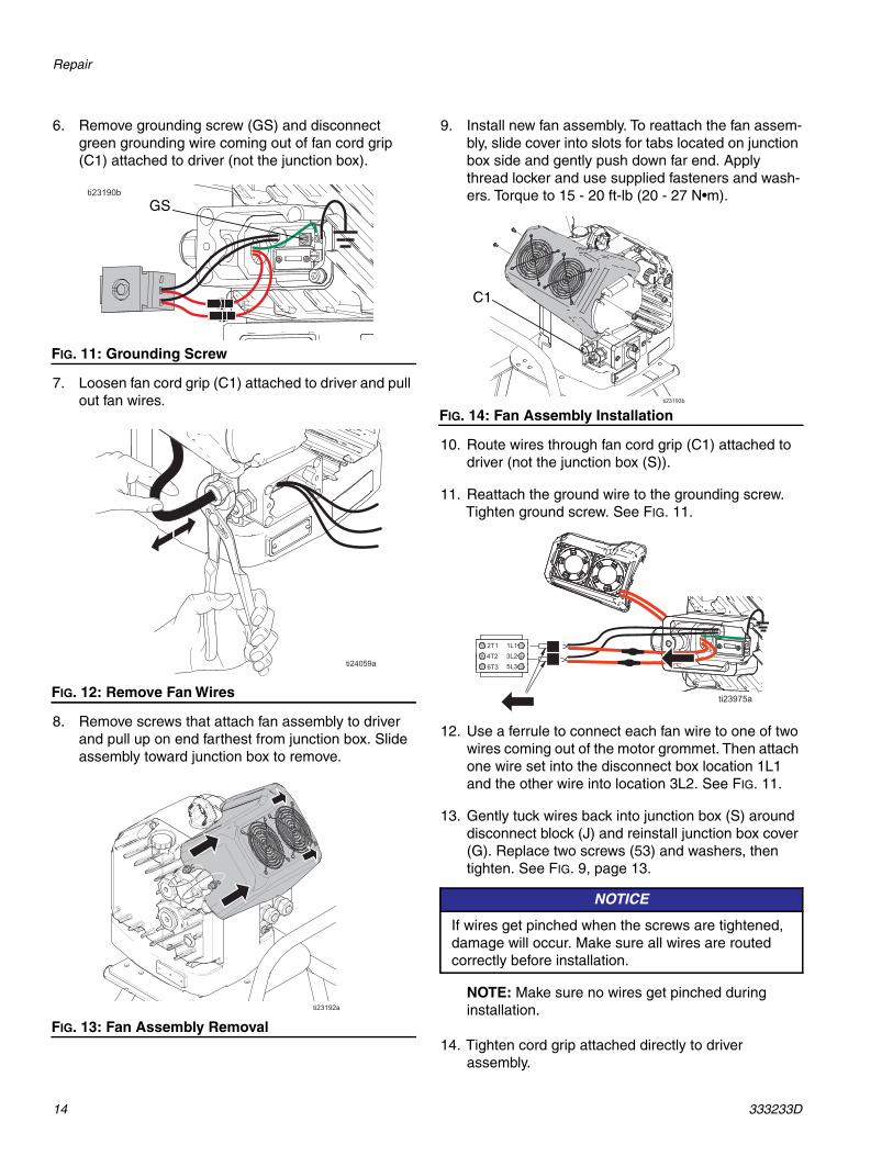
6. Remove grounding screw (GS) and disconnectgreen grounding wire coming out of fan cord grip(C1) attached to driver (not the junction box).
7. Loosen fan cord grip (C1) attached to driver and pullout fan wires.
8. Remove screws that attach fan assembly to driverand pull up on end farthest from junction box. Slideassembly toward junction box to remove.
9. Install new fan assembly. To reattach the fan assem-bly, slide cover into slots for tabs located on junctionbox side and gently push down far end. Applythread locker and use supplied fasteners and wash-ers. Torque to 15 - 20 ft-lb (20 - 27 N•m).
10. Route wires through fan cord grip (C1) attached todriver (not the junction box (S)).
11. Reattach the ground wire to the grounding screw.Tighten ground screw. See FIG. 11.
12. Use a ferrule to connect each fan wire to one of twowires coming out of the motor grommet. Then attachone wire set into the disconnect box location 1L1and the other wire into location 3L2. See FIG. 11.
13. Gently tuck wires back into junction box (S) arounddisconnect block (J) and reinstall junction box cover(G). Replace two screws (53) and washers, thentighten. See FIG. 9, page 13.
NOTE: Make sure no wires get pinched duringinstallation.
14. Tighten cord grip attached directly to driverassembly.
FIG. 11: Grounding Screw
FIG. 12: Remove Fan Wires
FIG. 13: Fan Assembly Removal
GS
FIG. 14: Fan Assembly Installation
NOTICE
If wires get pinched when the screws are tightened,damage will occur. Make sure all wires are routedcorrectly before installation.
C1
Repair
333233D 15
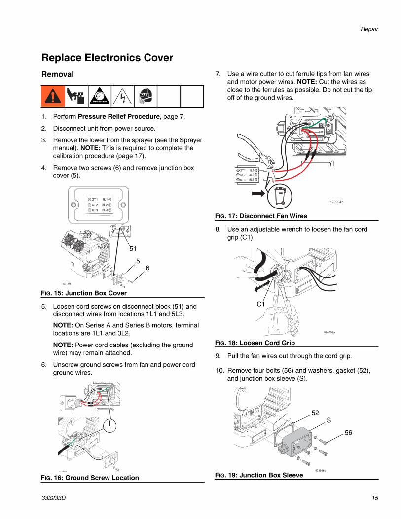
Replace Electronics Cover
Removal
1. Perform Pressure Relief Procedure, page 7.
2. Disconnect unit from power source.
3. Remove the lower from the sprayer (see the Sprayermanual). NOTE: This is required to complete thecalibration procedure (page 17).
4. Remove two screws (6) and remove junction boxcover (5).
5. Loosen cord screws on disconnect block (51) anddisconnect wires from locations 1L1 and 5L3.
NOTE: On Series A and Series B motors, terminallocations are 1L1 and 3L2.
NOTE: Power cord cables (excluding the groundwire) may remain attached.
6. Unscrew ground screws from fan and power cordground wires.
7. Use a wire cutter to cut ferrule tips from fan wiresand motor power wires. NOTE: Cut the wires asclose to the ferrules as possible. Do not cut the tipoff of the ground wires.
8. Use an adjustable wrench to loosen the fan cordgrip (C1).
9. Pull the fan wires out through the cord grip.
10. Remove four bolts (56) and washers, gasket (52),and junction box sleeve (S).
FIG. 15: Junction Box Cover
FIG. 16: Ground Screw Location
65
51
FIG. 17: Disconnect Fan Wires
FIG. 18: Loosen Cord Grip
FIG. 19: Junction Box Sleeve
C1
56
52S
Repair
16 333233D
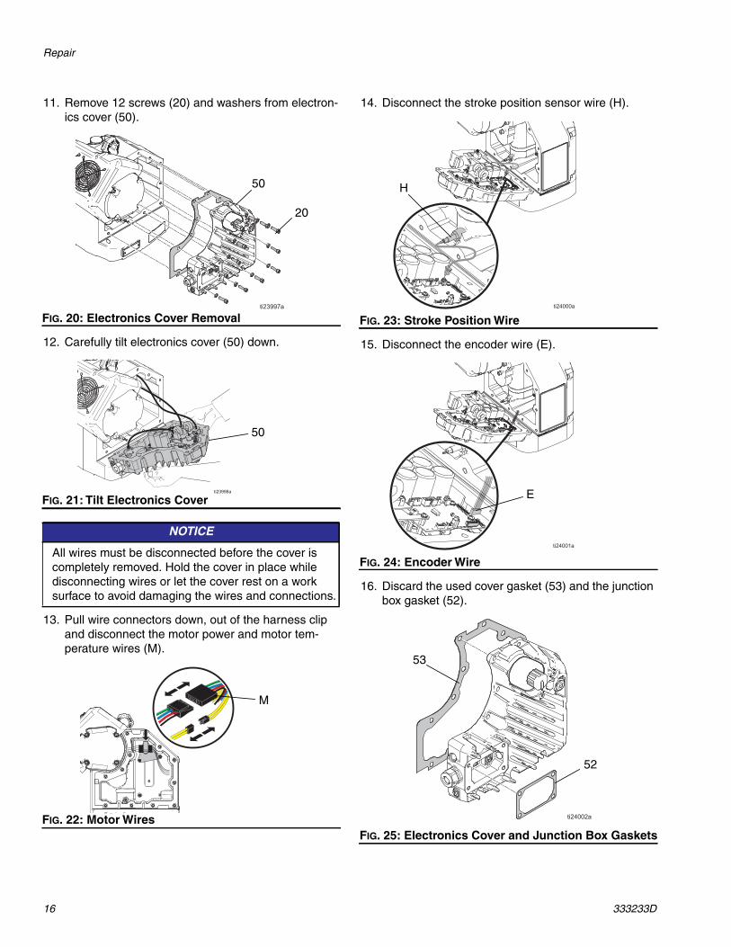
11. Remove 12 screws (20) and washers from electron-ics cover (50).
12. Carefully tilt electronics cover (50) down.
13. Pull wire connectors down, out of the harness clipand disconnect the motor power and motor tem-perature wires (M).
14. Disconnect the stroke position sensor wire (H).
15. Disconnect the encoder wire (E).
16. Discard the used cover gasket (53) and the junctionbox gasket (52).
FIG. 20: Electronics Cover Removal
FIG. 21: Tilt Electronics Cover
NOTICE
All wires must be disconnected before the cover iscompletely removed. Hold the cover in place whiledisconnecting wires or let the cover rest on a worksurface to avoid damaging the wires and connections.
FIG. 22: Motor Wires
50
20
50
M
FIG. 23: Stroke Position Wire
FIG. 24: Encoder Wire
FIG. 25: Electronics Cover and Junction Box Gaskets
H
E
53
52
Repair
333233D 17
Installation
1. Install the new cover gasket (included in the elec-tronics cover kit). See FIG. 25, page 16.
2. Reconnect all wires.
3. Install electronics cover (50) and tighten 12 screws(20). Torque to 15-20 ft-lb (20-27 N•m). See FIG. 20,page 16.
4. Install new junction box gasket.
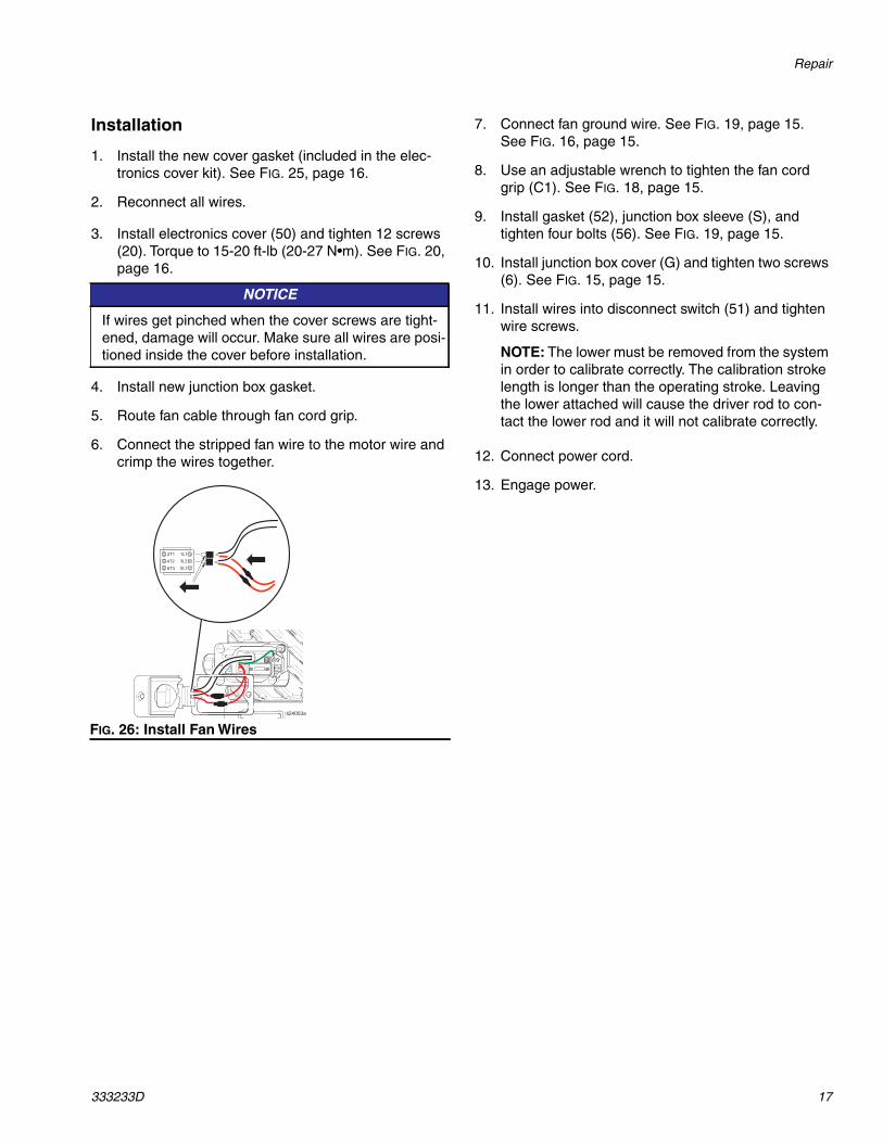
5. Route fan cable through fan cord grip.
6. Connect the stripped fan wire to the motor wire andcrimp the wires together.
7. Connect fan ground wire. See FIG. 19, page 15.See FIG. 16, page 15.
8. Use an adjustable wrench to tighten the fan cordgrip (C1). See FIG. 18, page 15.
9. Install gasket (52), junction box sleeve (S), andtighten four bolts (56). See FIG. 19, page 15.
10. Install junction box cover (G) and tighten two screws(6). See FIG. 15, page 15.
11. Install wires into disconnect switch (51) and tightenwire screws.
NOTE: The lower must be removed from the systemin order to calibrate correctly. The calibration strokelength is longer than the operating stroke. Leavingthe lower attached will cause the driver rod to con-tact the lower rod and it will not calibrate correctly.
12. Connect power cord.
13. Engage power.
NOTICE
If wires get pinched when the cover screws are tight-ened, damage will occur. Make sure all wires are posi-tioned inside the cover before installation.
FIG. 26: Install Fan Wires
Repair
18 333233D
Calibration
NOTE: The driver must be de-coupled from the lowerand must be able to cycle freely with no obstructions.
1. Cycle power to the driver by first turning the powerswitch (S) to OFF, and then to ON again.
2. Wait for the status indicator LED (L) to turn on solidor start blinking.
3. Within 30 seconds, rapidly turn the pressure controlknob (N) back and forth from 0 to 10 at least fivetimes and then set the knob back to 0. If the statusindicator LED (L) was solid before, it will begin blink-ing an encoder calibration error (code 8) during thecalibration process.
4. The driver output shaft (H) will run up and downslowly over the course of several minutes.
5. Midway through the auto-calibration process, thedriver output shaft (H) will pause as it moves to thenext step.
6. The driver output shaft (H) will move up and downfaster 5-6 times.
7. Ensure the auto-calibration process is completebefore continuing. Wait for the LED to stop blinking.
Repair Token Cable
1. Perform Pressure Relief Procedure, page 7.
2. Disconnect unit from power source.
3. Remove 12 screws (20) and washers fromelectronics cover (50). See FIG. 20, page 16.
4. Carefully tilt electronics cover (50) down.See FIG. 21, page 16.
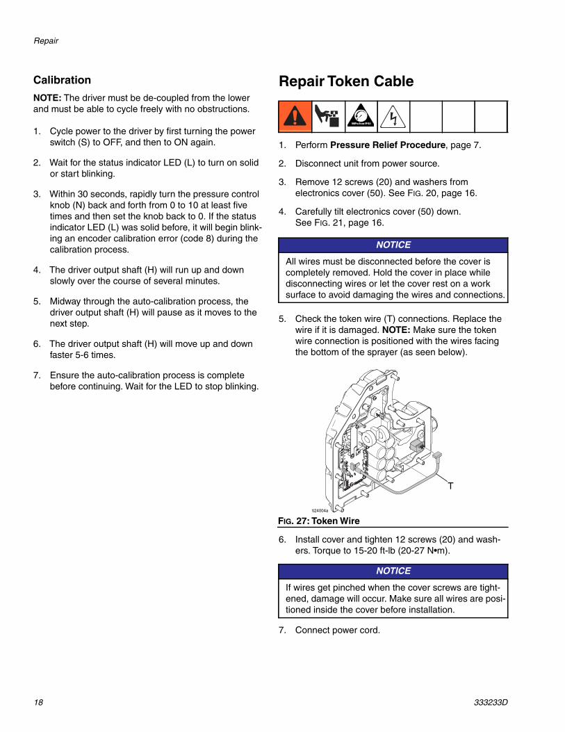
5. Check the token wire (T) connections. Replace thewire if it is damaged. NOTE: Make sure the tokenwire connection is positioned with the wires facingthe bottom of the sprayer (as seen below).
6. Install cover and tighten 12 screws (20) and wash-ers. Torque to 15-20 ft-lb (20-27 N•m).
7. Connect power cord.
NOTICE
All wires must be disconnected before the cover iscompletely removed. Hold the cover in place whiledisconnecting wires or let the cover rest on a worksurface to avoid damaging the wires and connections.
FIG. 27: Token Wire
NOTICE
If wires get pinched when the cover screws are tight-ened, damage will occur. Make sure all wires are posi-tioned inside the cover before installation.
T
Repair
333233D 19
Software Update Procedure
1. Perform Pressure Relief Procedure, page 7.
2. Disconnect unit from power source.
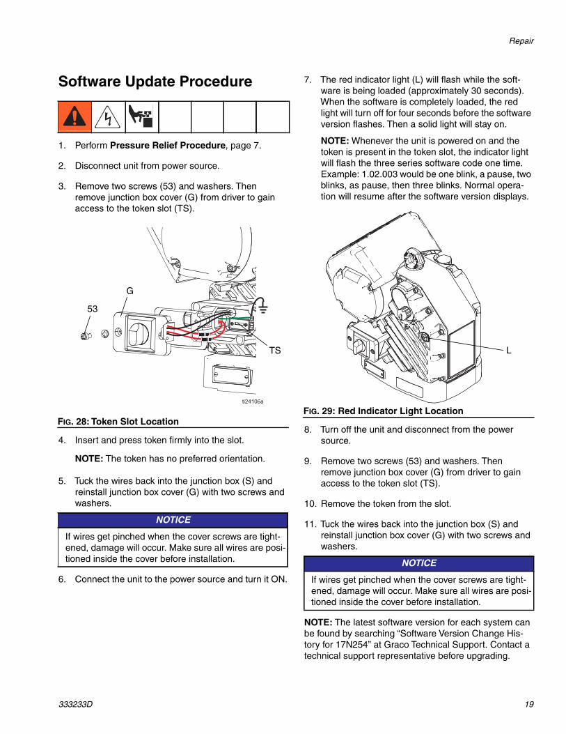
3. Remove two screws (53) and washers. Thenremove junction box cover (G) from driver to gainaccess to the token slot (TS).
4. Insert and press token firmly into the slot.
NOTE: The token has no preferred orientation.
5. Tuck the wires back into the junction box (S) andreinstall junction box cover (G) with two screws andwashers.
6. Connect the unit to the power source and turn it ON.
7. The red indicator light (L) will flash while the soft-ware is being loaded (approximately 30 seconds).When the software is completely loaded, the redlight will turn off for four seconds before the softwareversion flashes. Then a solid light will stay on.
NOTE: Whenever the unit is powered on and thetoken is present in the token slot, the indicator lightwill flash the three series software code one time.Example: 1.02.003 would be one blink, a pause, twoblinks, as pause, then three blinks. Normal opera-tion will resume after the software version displays.
8. Turn off the unit and disconnect from the powersource.
9. Remove two screws (53) and washers. Thenremove junction box cover (G) from driver to gainaccess to the token slot (TS).
10. Remove the token from the slot.
11. Tuck the wires back into the junction box (S) andreinstall junction box cover (G) with two screws andwashers.
NOTE: The latest software version for each system canbe found by searching “Software Version Change His-tory for 17N254” at Graco Technical Support. Contact atechnical support representative before upgrading.
FIG. 28: Token Slot Location
NOTICE
If wires get pinched when the cover screws are tight-ened, damage will occur. Make sure all wires are posi-tioned inside the cover before installation.
53
G
TS
FIG. 29: Red Indicator Light Location
NOTICE
If wires get pinched when the cover screws are tight-ened, damage will occur. Make sure all wires are posi-tioned inside the cover before installation.
L
Parts
20 333233D
Parts
Electric Driver
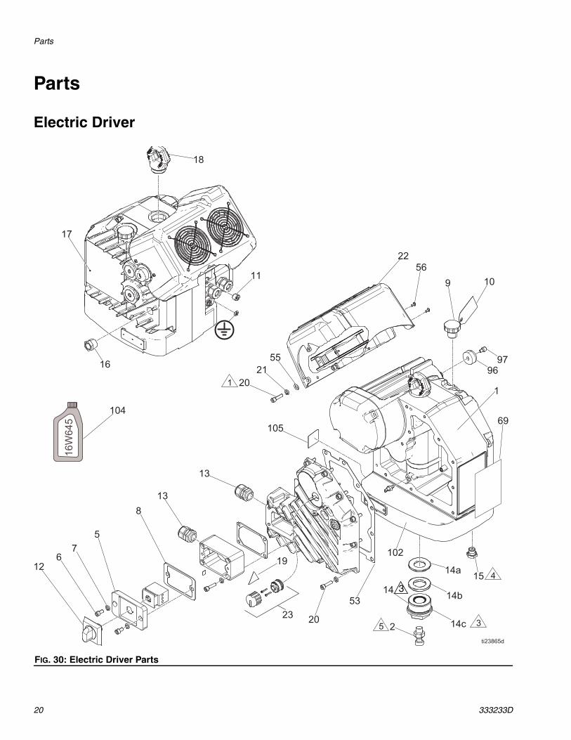
FIG. 30: Electric Driver Parts
3
Parts
333233D 21
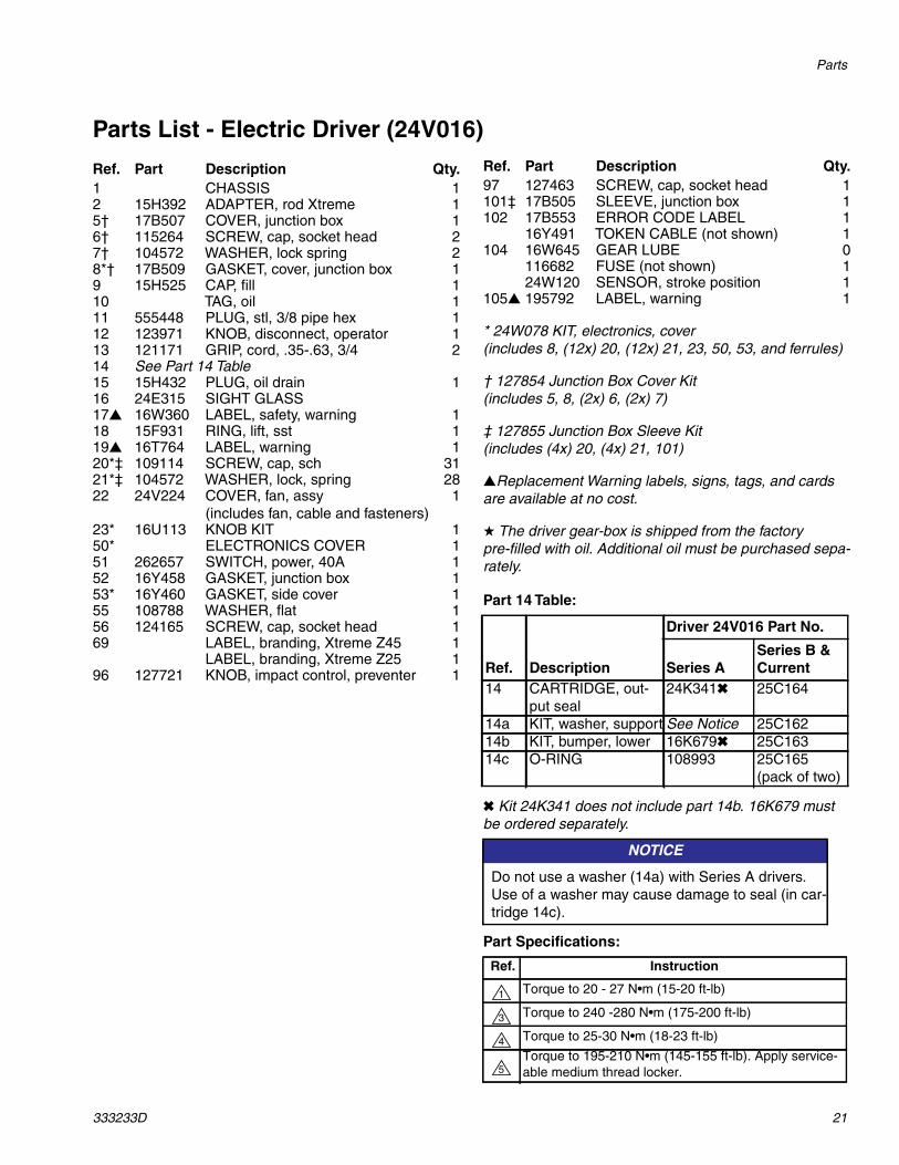
Parts List - Electric Driver (24V016)
Part 14 Table:
✖ Kit 24K341 does not include part 14b. 16K679 mustbe ordered separately.
Part Specifications:
Ref. Part Description Qty.1 CHASSIS 12 15H392 ADAPTER, rod Xtreme 15† 17B507 COVER, junction box 16† 115264 SCREW, cap, socket head 27† 104572 WASHER, lock spring 28*† 17B509 GASKET, cover, junction box 19 15H525 CAP, fill 110 TAG, oil 111 555448 PLUG, stl, 3/8 pipe hex 112 123971 KNOB, disconnect, operator 113 121171 GRIP, cord, .35-.63, 3/4 214 See Part 14 Table15 15H432 PLUG, oil drain 116 24E315 SIGHT GLASS17▲ 16W360 LABEL, safety, warning 118 15F931 RING, lift, sst 119▲ 16T764 LABEL, warning 120*‡ 109114 SCREW, cap, sch 3121*‡ 104572 WASHER, lock, spring 2822 24V224 COVER, fan, assy
(includes fan, cable and fasteners)1
23* 16U113 KNOB KIT 150* ELECTRONICS COVER 151 262657 SWITCH, power, 40A 152 16Y458 GASKET, junction box 153* 16Y460 GASKET, side cover 155 108788 WASHER, flat 156 124165 SCREW, cap, socket head 169 LABEL, branding, Xtreme Z45 1
LABEL, branding, Xtreme Z25 196 127721 KNOB, impact control, preventer 1
97 127463 SCREW, cap, socket head 1101‡ 17B505 SLEEVE, junction box 1102 17B553 ERROR CODE LABEL 1
16Y491 TOKEN CABLE (not shown) 1104 16W645 GEAR LUBE 0
116682 FUSE (not shown) 124W120 SENSOR, stroke position 1
105▲ 195792 LABEL, warning 1
* 24W078 KIT, electronics, cover(includes 8, (12x) 20, (12x) 21, 23, 50, 53, and ferrules)
† 127854 Junction Box Cover Kit(includes 5, 8, (2x) 6, (2x) 7)
‡ 127855 Junction Box Sleeve Kit(includes (4x) 20, (4x) 21, 101)
▲Replacement Warning labels, signs, tags, and cardsare available at no cost.
★ The driver gear-box is shipped from the factorypre-filled with oil. Additional oil must be purchased sepa-rately.
Ref. Description
Driver 24V016 Part No.
Series ASeries B &Current
14 CARTRIDGE, out-put seal
24K341✖ 25C164
14a KIT, washer, support See Notice 25C16214b KIT, bumper, lower 16K679✖ 25C16314c O-RING 108993 25C165
(pack of two)
NOTICE
Do not use a washer (14a) with Series A drivers.Use of a washer may cause damage to seal (in car-tridge 14c).
Ref. Instruction
Torque to 20 - 27 N•m (15-20 ft-lb)
Torque to 240 -280 N•m (175-200 ft-lb)
Torque to 25-30 N•m (18-23 ft-lb)
Torque to 195-210 N•m (145-155 ft-lb). Apply service-able medium thread locker.
Ref. Part Description Qty.
1
3
4
5
Parts
22 333233D
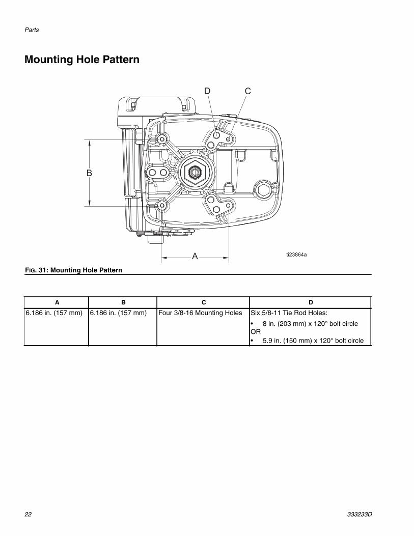
Mounting Hole Pattern
FIG. 31: Mounting Hole Pattern
A B C D
6.186 in. (157 mm) 6.186 in. (157 mm) Four 3/8-16 Mounting Holes Six 5/8-11 Tie Rod Holes:
• 8 in. (203 mm) x 120° bolt circleOR• 5.9 in. (150 mm) x 120° bolt circle
Wiring Diagram
333233D 23
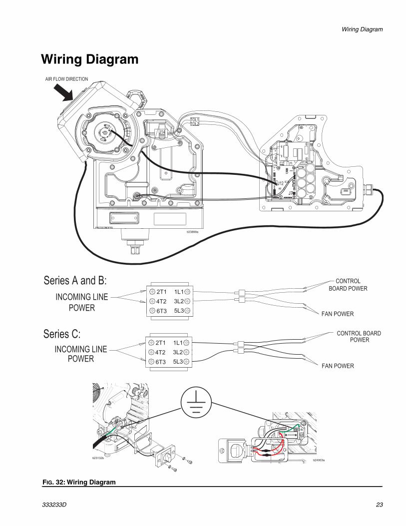
Wiring Diagram
FIG. 32: Wiring Diagram

Dimensions
24 333233D
Dimensions
Driver DimensionsA width 15.30 in (0.390 m)B depth 18.3 in (0.465 m)C mounted height 18.3 in (0.465 m)D total height 21.5 in (0.545 m)
-A-
A
B
C
D
Technical Data
333233D 25
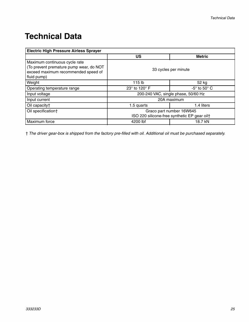
Technical Data
† The driver gear-box is shipped from the factory pre-filled with oil. Additional oil must be purchased separately.
Electric High Pressure Airless SprayerUS Metric
Maximum continuous cycle rate(To prevent premature pump wear, do NOTexceed maximum recommended speed offluid pump)
33 cycles per minute
Weight 115 lb 52 kgOperating temperature range 23° to 120° F -5° to 50° CInput voltage 200-240 VAC, single phase, 50/60 HzInput current 20A maximumOil capacity† 1.5 quarts 1.4 litersOil specification† Graco part number 16W645
ISO 220 silicone-free synthetic EP gear oil†Maximum force 4200 lbf 18.7 kN

All written and visual data contained in this document reflects the latest product information available at the time of publication.Graco reserves the right to make changes at any time without notice.
This manual contains English. MM 333233
Graco Headquarters: MinneapolisInternational Offices: Belgium, China, Japan, Korea
GRACO INC. AND SUBSIDIARIES • P.O. BOX 1441 • MINNEAPOLIS MN 55440-1441 • USA
Copyright 2016, Graco Inc. All Graco manufacturing locations are registered to ISO 9001.www.graco.com
Revision D, March 2017
Graco Standard WarrantyGraco warrants all equipment referenced in this document which is manufactured by Graco and bearing its name to be free from defects inmaterial and workmanship on the date of sale to the original purchaser for use. With the exception of any special, extended, or limited warrantypublished by Graco, Graco will, for a period of twelve months from the date of sale, repair or replace any part of the equipment determined byGraco to be defective. This warranty applies only when the equipment is installed, operated and maintained in accordance with Graco’s writtenrecommendations.
This warranty does not cover, and Graco shall not be liable for general wear and tear, or any malfunction, damage or wear caused by faultyinstallation, misapplication, abrasion, corrosion, inadequate or improper maintenance, negligence, accident, tampering, or substitution ofnon-Graco component parts. Nor shall Graco be liable for malfunction, damage or wear caused by the incompatibility of Graco equipment withstructures, accessories, equipment or materials not supplied by Graco, or the improper design, manufacture, installation, operation ormaintenance of structures, accessories, equipment or materials not supplied by Graco.
This warranty is conditioned upon the prepaid return of the equipment claimed to be defective to an authorized Graco distributor for verification ofthe claimed defect. If the claimed defect is verified, Graco will repair or replace free of charge any defective parts. The equipment will be returnedto the original purchaser transportation prepaid. If inspection of the equipment does not disclose any defect in material or workmanship, repairs willbe made at a reasonable charge, which charges may include the costs of parts, labor, and transportation.
THIS WARRANTY IS EXCLUSIVE, AND IS IN LIEU OF ANY OTHER WARRANTIES, EXPRESS OR IMPLIED, INCLUDING BUT NOT LIMITEDTO WARRANTY OF MERCHANTABILITY OR WARRANTY OF FITNESS FOR A PARTICULAR PURPOSE.
Graco’s sole obligation and buyer’s sole remedy for any breach of warranty shall be as set forth above. The buyer agrees that no other remedy(including, but not limited to, incidental or consequential damages for lost profits, lost sales, injury to person or property, or any other incidental orconsequential loss) shall be available. Any action for breach of warranty must be brought within two (2) years of the date of sale.
GRACO MAKES NO WARRANTY, AND DISCLAIMS ALL IMPLIED WARRANTIES OF MERCHANTABILITY AND FITNESS FOR APARTICULAR PURPOSE, IN CONNECTION WITH ACCESSORIES, EQUIPMENT, MATERIALS OR COMPONENTS SOLD BUT NOTMANUFACTURED BY GRACO. These items sold, but not manufactured by Graco (such as electric motors, switches, hose, etc.), are subject tothe warranty, if any, of their manufacturer. Graco will provide purchaser with reasonable assistance in making any claim for breach of thesewarranties.
In no event will Graco be liable for indirect, incidental, special or consequential damages resulting from Graco supplying equipment hereunder, orthe furnishing, performance, or use of any products or other goods sold hereto, whether due to a breach of contract, breach of warranty, thenegligence of Graco, or otherwise.
FOR GRACO CANADA CUSTOMERSThe Parties acknowledge that they have required that the present document, as well as all documents, notices and legal proceedings entered into,given or instituted pursuant hereto or relating directly or indirectly hereto, be drawn up in English. Les parties reconnaissent avoir convenu que larédaction du présente document sera en Anglais, ainsi que tous documents, avis et procédures judiciaires exécutés, donnés ou intentés, à la suitede ou en rapport, directement ou indirectement, avec les procédures concernées.
Graco InformationFor the latest information about Graco products, visit www.graco.com.For patent information, see www.graco.com/patents.
TO PLACE AN ORDER contact your Graco distributor or call to identify the nearest distributor.Phone: 612-623-6921 or Toll Free: 1-800-328-0211 Fax: 612-378-3505