340cf elsd installation and operation · 1.3 nebulization chamber drain ... 3.4.2 shut down...
TRANSCRIPT

340CF ELSDInstallation and Operation Guide
Part #69-5243-095Copyright © 2006
Revision G, July 25, 2016


ELSDSafety
iii
ELSDSafety
General Warnings Before installing, operating, or maintaining this equipment, it isimperative that all hazards and preventive measures are fullyunderstood. While specific hazards may vary according tolocation and application, take heed of the following generalwarnings:
WARNINGLiquids associated with this instrument may be classifiedas carcinogenic, biohazard, flammable, or radioactive.Should these liquids be used, it is highly recommended thatthis application be accomplished in an isolatedenvironment designed for these types of materials inaccordance with federal, state, and local regulatory laws,and in compliance with your company’s chemical/hygieneplan in the event of a spill.
AVERTISSEMENTEviter de répandre des liquides dangereux. Les liquides quisont analysés dans cet instrument peuvent êtrecancérigènes, hasards biologiques, inflammables, ouradioactifs. Si vous devez utiliser tels liquides, il est trèsrecommandé que vous le faites à l'intérieur d'unenvironnement isolé conçu pour tels liquides. Cetenvironnement isolé devrait être construit selon lesrèglements fédéraux, provinciaux, et locaux, aussi que leplan de votre compagnie qui concerne l'évènement d'unaccident avec les matières hasardeuses.
WARNINGAvoid hazardous practices! If you use this instrument inany way not specified in this manual, the protectionprovided by the instrument may be impaired.
AVERTISSEMENTÉviter les usages périlleux! Si vous utilisez cet instrumentd’une manière autre que celles qui sont specifiées dans cemanuel, la protection fournie de l’instrument peut êtreaffaiblie; cela augmentera votre risque de blessure.
WARNINGIf this system uses flammable organic solvents, TeledyneIsco recommends that you place this system in awell-ventilated environment, designed for these types ofmaterials. This environment should be constructed inaccordance with federal, state, and local regulations. Itshould also comply with your organization’s plan

ELSDSafety
iv
concerning chemical and hygiene mishaps. In all cases usegood laboratory practices and standard safety procedures.
AVERTISSEMENTCe système peut utiliser des dissolvants organiquesinflammables. Pour réduire le péril qui peut être causé parl'accumulation des vapeurs explosives, Teledyne Iscorecommande que vous installez ce système dans unenvironnement bien-aéré qui est conçu pour les matièreshasardeuses. Cet environnement devrait être construitselon les règlements fédéraux, provinciaux, et locaux.Aussi, il devrait se conformer au plan de votre organisationqui concerne les mésaventures de l'hygiène ou dechimique. En tout cas, utilisez toujours de pratiquesbonnes de la laboratoire et des procédures standardes dela sûreté.
Hazard Severity Levels This manual applies Hazard Severity Levels to the safety alerts,These three levels are described in the sample alerts below.
CAUTIONCautions identify a potential hazard, which if not avoided, mayresult in minor or moderate injury. This category can also warnyou of unsafe practices, or conditions that may cause propertydamage.
WARNINGWarnings identify a potentially hazardous condition, whichif not avoided, could result in death or serious injury.
DANGERDANGER – limited to the most extreme situationsto identify an imminent hazard, which if notavoided, will result in death or serious injury.

ELSDSafety
v
Hazard Symbols The equipment and this manual use symbols used to warn ofhazards. The symbols are explained below.
Hazard Symbols
Warnings and Cautions
The exclamation point within the triangle is a warning sign alerting you ofimportant instructions in the instrument’s technical reference manual.
The lightning flash and arrowhead within the triangle is a warning sign alert-ing you of “dangerous voltage” inside the product.
Symboles de sécurité
Ce symbole signale l’existence d’instructions importantes relatives au pro-duit dans ce manuel.
Ce symbole signale la présence d’un danger d’électocution.
Warnungen und Vorsichtshinweise
Das Ausrufezeichen in Dreieck ist ein Warnzeichen, das Sie daraufaufmerksam macht, daß wichtige Anleitungen zu diesem Handbuchgehören.
Der gepfeilte Blitz im Dreieck ist ein Warnzeichen, das Sei vor “gefährlichenSpannungen” im Inneren des Produkts warnt.
Advertencias y Precauciones
Esta señal le advierte sobre la importancia de las instrucciones del manualque acompañan a este producto.
Esta señal alerta sobre la presencia de alto voltaje en el interior delproducto.

ELSDSafety
vi

vii
340CF ELSD
Table of Contents
Section 1 Quick Start Guide
1.1 Connecting to the CombiFlash® Rf200 . . . . . . . . . . . . . . . . . . . . . . . . . . . . . . . . . . 1-11.2 Connecting to the CombiFlash® Torrent . . . . . . . . . . . . . . . . . . . . . . . . . . . . . . . . . 1-41.3 Nebulization Chamber Drain . . . . . . . . . . . . . . . . . . . . . . . . . . . . . . . . . . . . . . . . . . 1-61.4 Basic Operation . . . . . . . . . . . . . . . . . . . . . . . . . . . . . . . . . . . . . . . . . . . . . . . . . . . . . 1-6
Section 2 Introduction
2.1 Overview . . . . . . . . . . . . . . . . . . . . . . . . . . . . . . . . . . . . . . . . . . . . . . . . . . . . . . . . . . 2-12.2 Servicing . . . . . . . . . . . . . . . . . . . . . . . . . . . . . . . . . . . . . . . . . . . . . . . . . . . . . . . . . . 2-12.3 Operating Principles . . . . . . . . . . . . . . . . . . . . . . . . . . . . . . . . . . . . . . . . . . . . . . . . . 2-1
2.3.1 Nebulization . . . . . . . . . . . . . . . . . . . . . . . . . . . . . . . . . . . . . . . . . . . . . . . . . . 2-22.3.2 Evaporation . . . . . . . . . . . . . . . . . . . . . . . . . . . . . . . . . . . . . . . . . . . . . . . . . . 2-32.3.3 Detection . . . . . . . . . . . . . . . . . . . . . . . . . . . . . . . . . . . . . . . . . . . . . . . . . . . . . 2-3
2.4 Specifications . . . . . . . . . . . . . . . . . . . . . . . . . . . . . . . . . . . . . . . . . . . . . . . . . . . . . . . 2-4
Section 3 Installation
3.1 Unpacking . . . . . . . . . . . . . . . . . . . . . . . . . . . . . . . . . . . . . . . . . . . . . . . . . . . . . . . . . 3-13.2 Connections . . . . . . . . . . . . . . . . . . . . . . . . . . . . . . . . . . . . . . . . . . . . . . . . . . . . . . . . 3-1
3.2.1 Power . . . . . . . . . . . . . . . . . . . . . . . . . . . . . . . . . . . . . . . . . . . . . . . . . . . . . . . 3-13.2.2 Exhaust . . . . . . . . . . . . . . . . . . . . . . . . . . . . . . . . . . . . . . . . . . . . . . . . . . . . . 3-13.2.3 Location . . . . . . . . . . . . . . . . . . . . . . . . . . . . . . . . . . . . . . . . . . . . . . . . . . . . . 3-13.2.4 Communication . . . . . . . . . . . . . . . . . . . . . . . . . . . . . . . . . . . . . . . . . . . . . . . 3-13.2.5 Digital I/O Connections . . . . . . . . . . . . . . . . . . . . . . . . . . . . . . . . . . . . . . . . . 3-23.2.6 Gas Connections . . . . . . . . . . . . . . . . . . . . . . . . . . . . . . . . . . . . . . . . . . . . . . . 3-23.2.7 Fluid Connections . . . . . . . . . . . . . . . . . . . . . . . . . . . . . . . . . . . . . . . . . . . . . 3-23.2.8 Nebulization Chamber Drain . . . . . . . . . . . . . . . . . . . . . . . . . . . . . . . . . . . . 3-2
3.3 Connection to Teledyne Isco Instruments . . . . . . . . . . . . . . . . . . . . . . . . . . . . . . . . 3-33.3.1 Connecting to the CombiFlash® Rf200 . . . . . . . . . . . . . . . . . . . . . . . . . . . . 3-33.3.2 Connecting to the CombiFlash® Rf200 with 4X Module . . . . . . . . . . . . . . . 3-53.3.3 Connecting to the CombiFlash® Torrent Module . . . . . . . . . . . . . . . . . . . . 3-6
3.4 Conversion for HPLC Applications . . . . . . . . . . . . . . . . . . . . . . . . . . . . . . . . . . . . . 3-63.4.1 Operating Temperatures . . . . . . . . . . . . . . . . . . . . . . . . . . . . . . . . . . . . . . . . 3-93.4.2 Shut Down Procedure . . . . . . . . . . . . . . . . . . . . . . . . . . . . . . . . . . . . . . . . . . 3-9
3.5 Installation Qualification Checklist . . . . . . . . . . . . . . . . . . . . . . . . . . . . . . . . . . . . 3-10
Section 4 Operation
4.1 Instrument Controls . . . . . . . . . . . . . . . . . . . . . . . . . . . . . . . . . . . . . . . . . . . . . . . . . 4-14.1.1 Status Indicator Lights . . . . . . . . . . . . . . . . . . . . . . . . . . . . . . . . . . . . . . . . . 4-14.1.2 Status Alarm . . . . . . . . . . . . . . . . . . . . . . . . . . . . . . . . . . . . . . . . . . . . . . . . . 4-14.1.3 MENU|POWER Key . . . . . . . . . . . . . . . . . . . . . . . . . . . . . . . . . . . . . . . . . . . 4-14.1.4 Autozero Key . . . . . . . . . . . . . . . . . . . . . . . . . . . . . . . . . . . . . . . . . . . . . . . . . 4-24.1.5 Display Screens . . . . . . . . . . . . . . . . . . . . . . . . . . . . . . . . . . . . . . . . . . . . . . . 4-2
4.2 Operation . . . . . . . . . . . . . . . . . . . . . . . . . . . . . . . . . . . . . . . . . . . . . . . . . . . . . . . . . . 4-94.2.1 Start Up Procedure . . . . . . . . . . . . . . . . . . . . . . . . . . . . . . . . . . . . . . . . . . . . 4-94.2.2 Choosing Operating Conditions . . . . . . . . . . . . . . . . . . . . . . . . . . . . . . . . . . 4-9

340CF ELSDTable of Contents
viii
4.3 Operating Modes . . . . . . . . . . . . . . . . . . . . . . . . . . . . . . . . . . . . . . . . . . . . . . . . . . . 4-124.3.1 Automatic Operation (Default) . . . . . . . . . . . . . . . . . . . . . . . . . . . . . . . . . . 4-134.3.2 Manual Operation . . . . . . . . . . . . . . . . . . . . . . . . . . . . . . . . . . . . . . . . . . . . 4-13
4.4 Mobile Phase Considerations . . . . . . . . . . . . . . . . . . . . . . . . . . . . . . . . . . . . . . . . . 4-134.5 Default Method . . . . . . . . . . . . . . . . . . . . . . . . . . . . . . . . . . . . . . . . . . . . . . . . . . . . 4-14
List of Figures1-1 Preparing the Rf200 connection ports . . . . . . . . . . . . . . . . . . . . . . . . . . . . . . . . . . . 1-11-2 Connecting the Rf ports to the ELSD . . . . . . . . . . . . . . . . . . . . . . . . . . . . . . . . . . . 1-21-3 Connecting gas supply to ELSD . . . . . . . . . . . . . . . . . . . . . . . . . . . . . . . . . . . . . . . 1-21-4 Rf external detector cable connections . . . . . . . . . . . . . . . . . . . . . . . . . . . . . . . . . . 1-31-5 Replace the PEEK tee with the metal tee fitting . . . . . . . . . . . . . . . . . . . . . . . . . . 1-41-6 Torrent: disconnect tubing from bottom column connection . . . . . . . . . . . . . . . . . 1-51-7 Tee fitting for Torrent to ELSD . . . . . . . . . . . . . . . . . . . . . . . . . . . . . . . . . . . . . . . . 1-51-8 Attach drain adaptor; prime with mobile phase if desired . . . . . . . . . . . . . . . . . . 1-62-1 Thermo-Split chamber: Cooling . . . . . . . . . . . . . . . . . . . . . . . . . . . . . . . . . . . . . . . . 2-22-2 Thermo-Split chamber: Heating . . . . . . . . . . . . . . . . . . . . . . . . . . . . . . . . . . . . . . . 2-22-3 Evaporation and detection . . . . . . . . . . . . . . . . . . . . . . . . . . . . . . . . . . . . . . . . . . . . 2-33-1 Attach drain adaptor; prime with mobile phase if desired . . . . . . . . . . . . . . . . . . 3-23-2 Preparing the Rf200 connection ports . . . . . . . . . . . . . . . . . . . . . . . . . . . . . . . . . . . 3-33-3 Connecting the Rf ports to the ELSD . . . . . . . . . . . . . . . . . . . . . . . . . . . . . . . . . . . 3-33-4 Connecting gas supply to ELSD . . . . . . . . . . . . . . . . . . . . . . . . . . . . . . . . . . . . . . . 3-43-5 Rf external detector cable connections . . . . . . . . . . . . . . . . . . . . . . . . . . . . . . . . . . 3-43-6 Component arrangement for connection with Rf200 and 4X module . . . . . . . . . . 3-53-7 Coupler for connecting 4X tubing . . . . . . . . . . . . . . . . . . . . . . . . . . . . . . . . . . . . . . 3-53-8 Case top removal: Remove screws . . . . . . . . . . . . . . . . . . . . . . . . . . . . . . . . . . . . . . 3-63-9 ELSD Interior . . . . . . . . . . . . . . . . . . . . . . . . . . . . . . . . . . . . . . . . . . . . . . . . . . . . . . 3-73-10 Removal of Liquid Inlet plug . . . . . . . . . . . . . . . . . . . . . . . . . . . . . . . . . . . . . . . . . 3-73-11 Disconnect PTFE line from pump . . . . . . . . . . . . . . . . . . . . . . . . . . . . . . . . . . . . . 3-83-12 Disconnect pump harness . . . . . . . . . . . . . . . . . . . . . . . . . . . . . . . . . . . . . . . . . . . 3-84-1 Spray Chamber Temperature Effects – Sub-ambient . . . . . . . . . . . . . . . . . . . . . 4-104-2 Spray Chamber Temperature Effects – Elevated . . . . . . . . . . . . . . . . . . . . . . . . . 4-114-3 Drift Tube Temperature Effects . . . . . . . . . . . . . . . . . . . . . . . . . . . . . . . . . . . . . . 4-12
List of Tables2-1 340CF ELSD Specifications . . . . . . . . . . . . . . . . . . . . . . . . . . . . . . . . . . . . . . . . . . 2-43-1 Suggested Operating Temperatures for HPLC Gradient Separations . . . . . . . . . 3-95-1 Installation Qualification Checklist . . . . . . . . . . . . . . . . . . . . . . . . . . . . . . . . . . . 3-10

1-1
340CF ELSD
Section 1 Quick Start Guide
This section provides information specific to connecting theELSD unit to a Teledyne Isco instrument. For general infor-mation about installing the ELSD, refer to Section 3.2.
1.1 Connecting to theCombiFlash® Rf200
The CombiFlash Rf200 uses RFID (Radio Frequency Identifi-cation) technology to automate setting the parameters for purifi-cation runs and fraction collection.
To connect the ELSD to the Rf200:
1. On the Rf, disconnect the tubing from ports C and D.(Retain the tubing assembly in case it is needed againlater.)
Figure 1-1 Preparing the Rf200 connection ports
2. Connect the shorter tubing assembly to port C, and the lon-ger tubing assembly to port D (refer to Figure 1-2).
3. Connect the other ends of the tubing to either side of thetee fitting on the rear panel of the ELSD.
Disconnectports C & D

340CF ELSDSection 1 Quick Start Guide
1-2
Figure 1-2 Connecting the Rf ports to the ELSD
4. Connect a 65 ±5psi inert gas supply (such as nitrogen) tothe brass fitting on the lower left rear panel of the ELSD,with 1/8" O.D. tubing.
Figure 1-3 Connecting gas supply to ELSD
5. Connect the external detector cable (Isco part#250-0000-20) to the Rf (Figure 1-4).
6. Connect the other end of the cable to the ELSD, takingcare to observe polarity as indicated by the small tab onthe ground side of the connector (see Figure 1-4).
183cm
60cm

340CF ELSDSection 1 Quick Start Guide
1-3
Figure 1-4 Rf external detector cable connections
Ground(CU)
Ground
Rf200 Connection ELSD Connection

340CF ELSDSection 1 Quick Start Guide
1-4
1.2 Connecting to theCombiFlash® Torrent
The CombiFlash Torrent system is designed to handle a varietyof large-scale purification needs, with various methods of sampleintroduction and collection.
Connection of the Torrent to the ELSD requires the connectionpackage, part #60-5247-021. The package contains the following:
1. Tee fitting with reducer
2. Two 0.25" mounting spacers for tee
3. Two #6x1" pan head screws/flat washers/lock washers
4. 1 pc 1/16 OD x 0.02" ID x 6" long tubing
5. 1 pc 0.25 OD x 0.188" ID x 100cm long black PTFE tubingw/ metal nut and ferrule swaged on each end
6. 1 pc 0.25 OD x 0.188" ID x 100cm long black PTFE tubingw/ nut and ferrule swaged one end and a union on theother end
To connect the ELSD to the Torrent:
1. With a 3/32" Allen wrench, remove the PEEK tee fitting andmetal tubing from the rear panel of the ELSD unit (refer toFigure 1-5).
2. Using the two long screws with lock and flat washers,mount the metal tee fitting on the rear panel, aligning thetwo standoffs over the ELSD’s threaded mounting holes,and the mounting holes in the tee over the two standoffs.
Figure 1-5 Replace the PEEK tee with the metal tee fitting
3. Locate the 6" piece of tubing. Attach one end to the bottomof the metal tee fitting and the other end to the ELSD liq-uid inlet (refer to Figure 1-7). Tighten fittings to finger,tight.
4. On the Torrent, disconnect the black PTFE tubing endfrom the bottom column connection (Figure 1-6).
Standoffs (place overthreaded holes)
Threadedmounting holes
340CF ELSDSection 1 Quick Start Guide
1-5
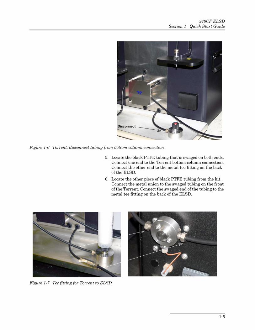
Figure 1-6 Torrent: disconnect tubing from bottom column connection
5. Locate the black PTFE tubing that is swaged on both ends.Connect one end to the Torrent bottom column connection.Connect the other end to the metal tee fitting on the backof the ELSD.
6. Locate the other piece of black PTFE tubing from the kit.Connect the metal union to the swaged tubing on the frontof the Torrent. Connect the swaged end of the tubing to themetal tee fitting on the back of the ELSD.
Figure 1-7 Tee fitting for Torrent to ELSD
Disconnect
Union

340CF ELSDSection 1 Quick Start Guide
1-6
1.3 NebulizationChamberDrain
Attach the stainless steel drain tube to the nebulization chamberdrain port located on the front of the instrument. Direct theoutlet of the tube to a collection vessel and empty the vesselwhen full.
Ensure that the instrument’s internal “P” trap is full duringoperation. Restricting the drain port with liquid is veryimportant to ensure detection sensitivity. Introduce 10 mL ofmobile phase into the drain using a squirt bottle or syringe.
Figure 1-8 Attach drain adaptor; prime with mobile phase if desired
1.4 Basic Operation Startup
1. Press MENU|POWER to turn on the ELSD.
2. Following power-up diagnostics, press MENU|POWER tobegin warm-up.
3. Turn on the gas supply to 65 ±5 psi.
Wait for the asterisk (*) to stop flashing before using it.
The signal displayed should be near 20mV. If not, pressAUTOZERO.
Shutdown
Press and hold MENU|POWER until the unit shuts down (about 5seconds).

2-1
340CF ELSD
Section 2 Introduction
2.1 Overview ELSDs are near universal detectors, primarily used in High Per-formance Liquid Chromatography (HPLC) though they havebeen used successfully in other types of chromatography as well.Their principal requirement is that the analyte be less volatilethan the mobile phase. An ELSD cannot detect highly volatileanalytes. However, most analytes of interest are less volatilethan the eluting solvents.
Evaporative light scattering detectors complement ultraviolet(UV) detection because they can detect most analytes, even thosethat do not absorb UV radiation, are stable during gradient elu-tions, and respond to the relative mass of the analyte – animportant feature that is useful when detecting unknown mate-rials. The ELSD is superior to the refractive index detector(RID), it can be used with gradient chromatography, it is not sus-ceptible to ambient temperature changes, and it does not producenegative peaks, which can be difficult to quantify. The ELSD doesnot respond to the mobile phase disruption seen as solvent frontpeaks in the void volume with UV and RI detectors, so earlyeluting analytes can be easily quantified. Mass spectrometry(MS) detection is also a universal detector, but its high cost andcomplexity have kept it from being widely used.In fact, the oper-ation requirements of MS closely match that of the ELSD. Thisallows the less expensive and complicated ELSD to be used as amethod development detector for methods to be used on the MSsystems.
2.2 Servicing A periodic maintenance kit is available from Teledyne Isco (part#60-5247-024). The kit contains instructions, parts, andequipment for servicing the ELSD. Contact the factory for moreinformation.
The ELSD should be cleaned and calibrated once a year by aqualified technician. Use water with a mild detergent, or fortougher stains, use Isopropyl Alcohol (IPA).
2.3 Operating Principles The ELSD employs a unique method of detection. The processinvolves the nebulization of the column eluent, transforming itinto an aerosol cloud. As this cloud travels through a heated zonewithin the instrument, the more volatile mobile phase evapo-rates, leaving a smaller cloud of analyte particles. These particlespass through a beam of light, scattering some of the light, whichis converted into an electronic signal.

340CF ELSDSection 2 Introduction
2-2
2.3.1 Nebulization Nebulization transforms the liquid phase leaving the column intoan aerosol cloud of fine droplets. The size and uniformity of thedroplets are extremely important in achieving sensitivity andreproducibility. The ELSD uses a special concentric flow nebu-lizer and a constant flow of an inert gas to ensure a narrowdroplet size distribution. Our nebulizer is constructed entirelyfrom PTFE, which accumulates deposits less than either glass orstainless steel.
To handle flow rates and mobile phases common in HPLC, allELSDs need a way to divert part of the aerosol cloud to waste.The ELSD uses a patent pending Thermo-Split technology.Our Thermo-Split chamber combines a gentle bend with tem-perature controlled walls. When the aerosol exiting the nebulizerencounters a cool environment, it partially condenses into largerparticles whose momentum carries them into the wall and downthe drain.
With cooling, the particles con-dense and increase in size. Theyare carried into the walls of thebend and exit via the drain.
Figure 2-1 Thermo-Split chamber: Cooling
With heat, the particles decreasein size and all pass the bend inthe Thermo-Split chamber.
Figure 2-2 Thermo-Split chamber: Heating
With the Temperature control option installed, the temperatureof the Spray Chamber may be elevated. As the aerosol traversesthe chamber, it partially evaporates, shifting the particle size dis-tribution low enough for essentially all the particles to negotiatethe bend. These operating conditions may be useful for specialapplications. Under these conditions a majority of the aerosolparticles pass through the chamber and are carried into theevaporative zone.

340CF ELSDSection 2 Introduction
2-3
2.3.2 Evaporation After passing through thenebulization chamber, theaerosol cloud is propelledthrough the heated evap-oration tube, assisted bythe carrier gas. In theevaporation tube, thesolvent is volatilized toproduce part i c les ordroplets of pure analyte.
The temperature of thedrift tube is set at thetemperature required toevaporate the solvent.The temperature is keptas low as possible to avoidparticle shape distortion,evaporat ion of theanalyte or when workingwith thermally sensitivecompounds.
Figure 2-3 Evaporation and detection
2.3.3 Detection The particles emerging from the evaporation tube enter theoptical cell, where the sample particles pass through the lightemitted by a low-power laser. The particles scatter the light,which is detected by a silicon photodiode located at a 90° anglefrom the laser. A light trap is located opposite the laser to collectthe light not scattered by particles. The quantity of light detectedis proportional to the solute concentration and solute particlesize distribution. The photodiode produces a signal, which is sentto the outputs for collection.
340CF ELSDSection 2 Introduction
2-4
2.4 Specifications
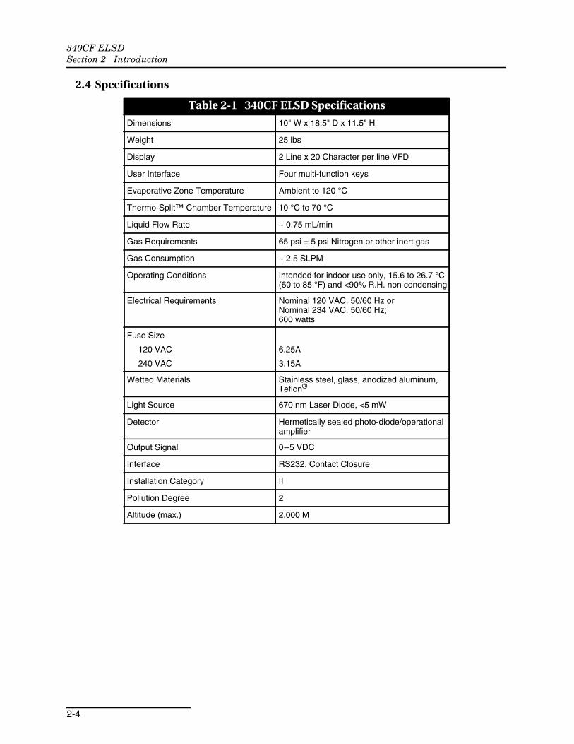
Table 2-1 340CF ELSD Specifications
Dimensions 10" W x 18.5" D x 11.5" H
Weight 25 lbs
Display 2 Line x 20 Character per line VFD
User Interface Four multi-function keys
Evaporative Zone Temperature Ambient to 120 °C
Thermo-Split™ Chamber Temperature 10 °C to 70 °C
Liquid Flow Rate ~ 0.75 mL/min
Gas Requirements 65 psi ± 5 psi Nitrogen or other inert gas
Gas Consumption ~ 2.5 SLPM
Operating Conditions Intended for indoor use only, 15.6 to 26.7 °C(60 to 85 °F) and <90% R.H. non condensing
Electrical Requirements Nominal 120 VAC, 50/60 Hz orNominal 234 VAC, 50/60 Hz;600 watts
Fuse Size
120 VAC
240 VAC
6.25A
3.15A
Wetted Materials Stainless steel, glass, anodized aluminum,Teflon®
Light Source 670 nm Laser Diode, <5 mW
Detector Hermetically sealed photo-diode/operationalamplifier
Output Signal 0–5 VDC
Interface RS232, Contact Closure
Installation Category II
Pollution Degree 2
Altitude (max.) 2,000 M

3-1
340CF ELSD
Section 3 Installation
3.1 Unpacking Unpack carefully and confirm that all the items are present. TheELSDs come in a high quality shipping container, engineered toavoid damage in transit. Save the shipping container and pack-aging for future shipments.
3.2 Connections The following sections provide general connection information forthe ELSD unit. For information about connecting the ELSD toTeledyne Isco instruments, refer to Section 3.3.
3.2.1 Power The ELSD operates at 120V or 234V, 50/60 Hz. Confirm that theELSD is configured for the correct voltage before plugging it intoline voltage. The voltage configuration is listed on the serial tag.If the voltage listed is incorrect, please contact your localTeledyne Isco representative.
Plug the modular power cord provided into the power inputmodule on the back of the detector. The power cord is the dis-connect device for the unit. Therefore, select a power outlet thatis nearby and unobstructed, allowing easy access for discon-nection in the event of an emergency.
3.2.2 Exhaust The ELSD exhaust is a ½" O.D. stainless steel tube. Use ½" I.D.tubing to connect to a fume hood during operation. Alternately,connect tubing and direct to a cooled collection vessel for laterdisposal.
3.2.3 Location The ELSD rear panel has a fan for cooling. Position theinstrument so that the rear panel is at least 5cm from any wall orobject, to allow free movement of air.
3.2.4 Communication
An output jack can be found on the back of the ELSD for con-nection to The CombiFlash Rf200. The maximum signal output is5V.
CAUTIONObserve polarity when connecting to this output. Refer toSection 3.3 for complete details about connection.
Analog Voltage Output
Circuitcommon
340CF ELSDSection 3 Installation
3-2
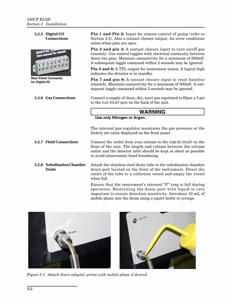
3.2.5 Digital I/OConnections
Pin 1 and Pin 2: Input for remote control of pump (refer toSection 4.3). Also a contact closure output. An error conditionsexists when pins are open.
Pin 3 and pin 4: A contact closure input to turn on/off gasremotely. Gas control toggles with electrical continuity betweenthese two pins. Maintain connectivity for a minimum of 500mS.A subsequent toggle command within 2 seconds may be ignored.
Pin 5 and 6: A TTL output for instrument status. A logical highindicates the detector is in standby.
Pin 7 and pin 8: A contact closure input to reset baselineremotely. Maintain connectivity for a minimum of 500mS. A sub-sequent toggle command within 2 seconds may be ignored.
3.2.6 Gas Connections Connect a supply of clean, dry, inert gas regulated to 65psi ± 5 psito the GAS INLET port on the back of the unit.
WARNINGUse only Nitrogen or Argon.
The internal gas regulator maintains the gas pressure at thefactory set value displayed on the front panel.
3.2.7 Fluid Connections Connect the outlet from your column to the LIQUID INLET on thefront of the unit. The length and volume between the columnoutlet and the detector inlet should be kept as short as possibleto avoid unnecessary band broadening.
3.2.8 Nebulization ChamberDrain
Attach the stainless steel drain tube to the nebulization chamberdrain port located on the front of the instrument. Direct theoutlet of the tube to a collection vessel and empty the vesselwhen full.
Ensure that the instrument’s internal “P” trap is full duringoperation. Restricting the drain port with liquid is veryimportant to ensure detection sensitivity. Introduce 10 mL ofmobile phase into the drain using a squirt bottle or syringe.
Figure 3-1 Attach drain adaptor; prime with mobile phase if desired
Rear Panel Connectorfor Digital I/O
1 2 3 4 5 6 7 8

340CF ELSDSection 3 Installation
3-3
3.3 Connection toTeledyne IscoInstruments
This section provides information specific to connecting theELSD unit to a Teledyne Isco instrument.
3.3.1 Connecting to theCombiFlash® Rf200
The CombiFlash Rf200 uses RFID (Radio Frequency Identifi-cation) technology to automate setting the parameters for purifi-cation runs and fraction collection.
To connect the ELSD to the Rf200:
1. On the Rf200, disconnect the tubing assembly from ports Cand D. (Retain the tubing assembly in case it is neededagain later.)
Figure 3-2 Preparing the Rf200 connection ports
2. Connect the shorter tubing assembly to port C, and the lon-ger tubing assembly to port D.
3. Connect the other ends of the tubing to either side the teefitting on the rear panel of the ELSD.
Figure 3-3 Connecting the Rf ports to the ELSD
Disconnectports C & D
183cm
60cm

340CF ELSDSection 3 Installation
3-4
4. Connect an inert gas supply (such as nitrogen) to the brassfitting on the lower left rear panel of the ELSD, with 1/8"O.D. line.
Figure 3-4 Connecting gas supply to ELSD
5. Connect the external detector cable (Isco part#250-0000-20) to the Rf200 (Figure 3-5).
6. Connect the other end of the cable to the ELSD, takingcare to observe polarity as indicated by the small tab onthe ground side of the connector.
Figure 3-5 Rf external detector cable connections
Ground(CU)
Ground
Rf200 Connection ELSD Connection

340CF ELSDSection 3 Installation
3-5
3.3.2 Connecting to theCombiFlash® Rf200with 4X Module
1. Place the ELSD next to the Rf200, opposite the 4X module,as shown in Figure 3-6.
2. Connect the 4X tubing to the Rf200, except for the tubingmarked "D," according to the 4X instructions.
Figure 3-6 Component arrangement for connection withRf200 and 4X module
3. Connect the 4X tubing marked "D" to the shorter tubingassembly from the 340C kit, using the coupler, as shown inFigure 3-7.
Figure 3-7 Coupler for connecting 4X tubing
4. Connect the other end of the shorter tubing assembly tothe tee fitting on the back of the ELSD detector.
4X Module Rf200 ELSD
4X Module
ELSD tee fitting

340CF ELSDSection 3 Installation
3-6
5. Connect the longer tubing assembly to the D port on theRf200, and to the other side of the tee fitting on the back ofthe ELSD detector.
3.3.3 Connecting to theCombiFlash® TorrentModule
The CombiFlash Torrent system is designed to handle a varietyof large-scale purification needs, with various methods of sampleintroduction and collection.
The Torrent can be configured for use with Teledyne Isco’s 340CFELSD.
The data connection between the Torrent and the ELSD must bemade via the DETECTOR port on the rear panel of either aTeledyne Isco Foxy R2 fraction collector or a Teledyne Isco frac-tionation valve.
For complete information about connecting to the CombiFlashTorrent, refer to Section 2 of the Torrent user manual.
3.4 Conversion for HPLCApplications
The following instructions are for preparation of the ELSD forHPLC applications. Additional fittings/connectors for HPLCpump connection are user-supplied.
Before performing conversion steps, disconnect the power cordfrom the back of the unit.
1. Turn the ELSD onto its side and remove the case top byremoving the four screws holding it in place (Figure 3-8.Turn the ELSD upright again.
Figure 3-8 Case top removal: Remove screws
Refer to Figure 3-9 for component locations in subsequent steps.

340CF ELSDSection 3 Installation
3-7
Figure 3-9 ELSD Interior
2. Remove the four 1/4" nuts holding the gusset in place.
3. Remove the 5/16" nut and the Liquid Inlet plug from thefront panel.
Figure 3-10 Removal of Liquid Inlet plug
4. Cut the tape to free the PTFE line from the drift tube.
5. Disconnect the PTFE line from the internal pump.
Liquid Inletplug
(hiddenbehind
gusset)
Tape(cut)
PTFE tubing
PTFE tubingpumpconnection
Pump motor
1/4" nuts (4)
Drift tube
Removegusset
Removenut

340CF ELSDSection 3 Installation
3-8
Figure 3-11 Disconnect PTFE line from pump
6. Route the line from the pump out through the Liquid Inletopening in the front panel.
7. Disconnect the harness from the pump motor.
Figure 3-12 Disconnect pump harness
8. On the Home Screen, set the Gain (GX) to HPLC.

340CF ELSDSection 3 Installation
3-9
3.4.1 OperatingTemperatures
3.4.2 Shut Down Procedure For HPLC applications, the ELSD must count down to thestandby state.
Press MENU|POWER until the standby countdown begins. Theunit will enter standby at the end of five minutes. Once the unitis in the standby state, turn off the laser and heaters.
If there are no leaks between your gas source and the ELSD, youdo not have to turn the gas off at the source.
Table 3-1 Suggested Operating Temperatures for HPLC Gradient Separations
Solvent @ 1.0mL/min. Drift Tube Temperature, °C Spray Chamber Temperature, °C
90/10 Water/METHANOL 45 15
90/10 Methanol/WATER 65 50
50/50 Methanol/Water 60 30
Acetonitrile 60 50
Methanol 60 50
Water 45 10

340CF ELSDSection 3 Installation
3-10
3.5 InstallationQualificationChecklist
Table 5-1 may be completed to verify and document the installationprocedures contained in this section of the manual.
Table 5-1 Installation Qualification Checklist
Step DescriptionInstallerInitials
OperatorInitials
3.1 Unpacking
3.1 Unpacking
Connections
3.2.1 Power
3.2.2 Exhaust
3.2.4 Communication
3.2.5 Digital I/O Connections
3.2.6 Gas Connections
3.2.7 Fluid Connections
3.2.8 Nebulization Chamber Drain
3.3.1 Connecting to the CombiFlash® Rf200
3.3.3 Connecting to the CombiFlash® TorrentModule
Certification of Section 3 Completion
Installer Name (print):
Installer Signature:
Date:
Operator Name (print):
Operator Signature:
Date:
Comments:

4-1
340CF ELSD
Section 4 Operation
4.1 Instrument Controls The ELSD is controlled via four multi-function keys on the frontpanel labeled MENU|POWER, ▲, ▼, and AUTOZERO. The ELSDfeatures a 2 line vacuum florescent display and a row of statuslights to aid in the operation of the detector.
4.1.1 Status Indicator Lights The status lights below the display provide a visual indication ofthe conditions of the ELSD. From left to right the function of thestatus lights are:
1. Spray Chamber Heater: The yellow light is illuminatedwhen the heater is active, blinks when the spray chamberis being controlled at the set temperature, and off when thespray chamber is cooling to a lower temperature.
2. Drift Tube heater: The yellow light is illuminated when theheater is active, blinks when the drift tube is being con-trolled at the set temperature, and off when the drift tubeis cooling to a lower temperature.
3. Optic Cell Heater: The yellow light is illuminated when theheater is active, blinks when the optical cell is being con-trolled at the set temperature, and off when the optics cellis cooling to a lower temperature.
4. Laser power: The green light is illuminated when the laseris on and stable and off when the laser is off. The lightblinks when laser power is low or unstable.
5. Gas Supply: The green light is on when the nebulizer gaspressure is within factory set limits, and the gas valve isopen. The green light will blink if a pressure error exists.The green light will be off if the gas valve has been turnedoff.
6. Ready Condition: The green light is illuminated when alloperating conditions are met and no error conditions exist.
4.1.2 Status Alarm The status alarm sounds when the detector status changes fromnot ready to ready or from ready to not ready. The alarm is 10short beeps repeated every 30 seconds. Pressing the AUTOZEROkey resets the alarm. The alarm can be disabled via the ControlPage menu screen.
4.1.3 MENU|POWER Key The MENU|POWER key is a multi-function key. An audible beep isheard when the key is activated. When the instrument is off,press the MENU|POWER key to turn the ELSD on. Note that whenthe power cord is plugged in the MENU|POWER key is dimly illu-minated from behind with a blue light. When the MENU|POWERkey is used to turn on the ELSD, the backlighting expands to the

340CF ELSDSection 4 Operation
4-2
other keys. Once the ELSD is powered up the MENU|POWER keyis used to view error conditions, cycle through the menu, acceptchanges to set points, enter standby mode, and turn the poweroff.
Error condition exist when the ready light is not illuminated andwhen the * appears in the upper right corner of the display. Pressthe MENU|POWER key and a description of the error is displayedin the window. The display will cycle through all error conditions.
Pressing the MENU|POWER key once, when no error conditionsexist, or twice times, if an error condition exists, enters the menuscreen.
Pressing the MENU|POWER key twice, when no error conditionsexist, or three times, if an error condition exists, enters thestand-by count down screen. Standby mode should be used whenthe system is being shutdown. When the detector enters stand-bycount down mode a timer is started. After the time had expiredthe gas solenoid is closed, shutting off the flow of the nebuli-zation gas, the laser is turned off, and the heaters are disabled.
To turn the power off, press and hold the MENU|POWER key for 5seconds. Wait at least 10 seconds before turning the instrumenton, after it has been turned off.
4.1.4 Autozero Key When the AUTOZERO key is depressed the ELS Detection signalwill reset to about 20mV. An audible beep is heard when the keyis activated. When the detector is in the menu mode, theAUTOZERO functions as an escape key, abolishing any changesmade. The AUTOZERO key is also used to reset the status alarm.
4.1.5 Display Screens The ELSD uses one of four screens to aid in the operation of thedetector:
Startup Screen
The “>” moves from left to the right while the program is loaded.The process ends when “>” reaches the far right.
After loading the program, the system begins running diag-nostics. Pressing the MENU|POWER key exits the start-up processwithout completing the diagnostics. If the MENU|POWER key ispressed before the completion of the diagnostics, the ELSDenters a special diagnostic mode.
Program Loading
>>>>>>>>
Running Diagnostics
Checking Laser Power

340CF ELSDSection 4 Operation
4-3
When the ELSD finishes the start-up process it enters thestand-by mode. Press the MENU|POWER key to exit and enter theHOME Screen.
Home Screen
Pushing ▲ or ▼keys will circulate XX section to review oper-ation condition. SC, DT, OC and ET sections display their setpoints to the degree for 5 seconds when selected. Then theydisplay the actual temperatures to the tenth of a degree.
Pushing MENU|POWER key will bring up the Menu screen. If thekey is pushed within 5 seconds after an arrow key was pushed,the selection at XX will be displayed. Otherwise, the timer pagewill always be the first menu page displayed.
If there is an asterisk (*) at the upper right corner, pushingMENU|POWER key will bring up a screen to explain what’s wrong:
XX = SC, DT, OC, ET, RST, BLN, GAS, FLT or BFT, CL, GX,FS
SC = Spray Chamber (setpoint: 10°C to 70°C;readout range: -10.0°C to 120.0°C)
DT = Drift Tube (setpoint: 22°C to 120°C;readout range: -10.0°C to120.0°C)
OC = Optical Cell (setpoint: 22°C to 70°C;readout range: -10.0°C to 120.0°C)
ET = Exhaust Tube (setpoint: 22°C to 70°C;readout range: -10.0°C to 120.0°C)
RST= Reset baseline to about 20mV.
BLN = Baseline reading (5000.000 – 0.000mV)
GAS = Gas (0.0 to130.0psi)
FLT or BFT = Baseline Filter(OFF, weight 1 to 10, FLT or BFT)
CL = Calibration (default 20%, or 1V; 100% = 5V)
GX = Gain (PREP (default) or HPLC (x10 resolution)
FS = Full Scale (10mv or 5V (default))
ELSD is in Standby Mode
Diagnostics Complete
Push PWR to exit
Laser Power OK
ELS DetectionXX
20.000mV 20.0°C

340CF ELSDSection 4 Operation
4-4
RST/BLN Screen
When RST is selected from the menu screen, it will display “RSTBaseline” for 5 seconds. Pushing MENU|POWER key during thisperiod will reset the ELS Detection signal to about 20mV. [Usingthe AUTOZERO key can also reset the baseline.] After 5 seconds,the display changes to BLN and displays the voltage offset by theautozero function. This value is important to note for each set ofoperating conditions. If the value is high, greater than 500mV,the mobile phase is not being evaporated completely and thetemperature set points should be modified. Other contaminatesin the system can also affect this reading.
Menu Screen
Pressing the MENU|POWER key once, when no error conditionsexist, or twice times, if an error condition exists, enters the menuscreen.
Push ▲ or ▼ keys to select the menus.
Push MENU|POWER twice to return to the Home screen.
Available Menus:• [Spray Chamber Page] Sets Spray Chamber temper-
ature.
• [Drift Tube Page] Sets Drift Tube, optical cell andexhaust tube temperatures.
• [Control Page] Sets Run/Standby mode, on/off Laser,on/off Alarm.
• [Timer] Sets duration of the shut down time.
• [Filter Page] Sets the type and weight of filter for noisefiltration
• [Load Method Page] Loads one of ten methods.
• [Save Method Page] Saves a method
• [Calibration Page] Attenuates or amplifies the detectoroutput
• [Detector Gain Page] Changes Gain
• [Full Scale Page] Changes Full Scale
ELS Detection RST
20.000mV Baseline
ELS Detection BLN
20.000mV 221.22
<<MENU>>
[Spray Chamber Page]

340CF ELSDSection 4 Operation
4-5
Spray Chamber Page
The reading under SPRAY CHAMBER is the current temper-ature. The reading under SET is the setpoint.
Pushing ▲ or ▼ keys to change a setpoint at 1°C increment.
Pushing MENU|POWER key to accept the change and go back toHome screen.
Pushing AUTOZERO key to abolish the change and go back toHome screen.
Drift Tube Page
The reading under DRIFT TUBE is the current temperature.The reading under SET is the setpoint. The temperatures of theoptical cell and the exhaust tube are controlled at the same tem-perature as that of DRIFT TUBE but their maximum temper-ature is limited.
Pushing ▲ or ▼ keys to change a set point at 1°C increment.
Pushing MENU|POWER key to accept the change and go back toHome screen.
Pushing AUTOZERO key to abolish the change and goes back toHome screen.
Control Page
[Run], [Standby], [Laser Off] or [Laser On], [Turn off Sound] or[Turn on Sound]
Use ▲ or ▼ keys to select an action.
Push MENU|POWER key to take an action and go back Homescreen.
Push AUTOZERO key to keep the current state and go back Homescreen.
If the display reads Laser Off or Laser On, pushing MENU|POWERkey will turn the laser off or on. The laser may take up to 30minutes to stabilize when it has been turned off, and on again.
If the display reads Turn off Sound or Turn on Sound, pushingMENU|POWER key will turn the status alarm off or on. The statusalarm sounds when the detector status changes from not ready to
SPRAY CHAMBER SET
10.0°C 10°C
DRIFT TUBE SET
40.0°C 40°C
Power Control:
[Run]

340CF ELSDSection 4 Operation
4-6
ready or from ready to not ready. The alarm is 10 short beepsrepeated every 30 seconds. Pressing the AUTOZERO key resets thealarm.
Timer Page
1 min to 60 min
Use ▲ or ▼ keys to extend or reduce countdown interval.
Push MENU|POWER key to save the modified countdown intervalbut cancel countdown and return to home screen.
Push AUTOZERO key to cancel the countdown, keep the previousinterval and go back Home screen.
The timer default value is 5 minutes and is the recommendedtime. The time can be increased up to 60 minutes or decreaseddown to 1 min.
Filter Page
OFF, 1 to 10, FLT or BFT
Use ▲ or ▼ keys to select an action.
Push MENU|POWER key to take an action and go back Homescreen.
Push AUTOZERO key to keep the current state and go back Homescreen.
There are two filter types to choose from FLT and BFT. The filtertype is selected at the top of the menu after weight 10. Select FLTor BFT and push the MENU|POWER KEY to enter. Then enter thefilter menu again and selected the appropriate filter weight.Filter weight is the level of baseline noise filtration. OFF indi-cates no filtration. 10 is maximum filtration. In most cases, selectBFT for baseline filtering. The FLT setting applies a RC filter tothe entire signal. For high-speed chromatography, less than a 5sec peak width, select BFT and turn the weight OFF. If the peakwidths are 5 to 30 seconds use the BFT filter with a weight of 1 to10. For peak widths greater than 30 seconds, select the FLTsetting with a weight of 1 to 10. When the baseline filter is on, adramatic operation condition change (e.g. turning on/off attachedequipment), may upset the filter and cause baseline drifting. Thebaseline will stabilize again in a few minutes.
STANDBY COUNTDOWN
Set: 05min 05:00
DEPRESS PWR button 5
sec to turn off ELSD
Filter Weight:
1

340CF ELSDSection 4 Operation
4-7
Load Method Page
If the number selected has no method saved, METHOD NOTAVAILABLE will be displayed. If the non-volatile memory IC chipis damaged, the same message will be displayed.
NoteMethod Zero (0) contains a default method for normal andreverse phase purifications on a CombiFlash system when theELSD is shipped from the factory. Default method settings arelisted in Section 4.5.
Save Method Page
Up to 8 methods can be saved. Use the ▲ or ▼ keys to select amethod number and the MENU|POWER key to save the currentconditions to the selected method number. A method includesSpray Chamber Temperature Setpoint, Drift Tube TemperatureSetpoint, Filter Weight, Calibration Factor, and Detector Gain.
Calibration Page
20% to 100% in 1% increments
Use ▲ or ▼ keys to select an action. Use 20% with Combi-Flash systems.
Push MENU|POWER key to take an action and go back Homescreen.
Push AUTOZERO key to keep the current state and go back Homescreen.
This feature scales the detector output. This feature is useful tomatch individual detectors to each other for standardizationwithin a lab, or set the full scale output to a value other than 5Vor 10mV. At 100%, the signal is neither amplified nor attenuated.
LOAD METHOD:
0 1 2 3 4 5 6 7 8 9
SAVE METHOD:
0 1 2 3 4 5 6 7 8
Calibration:
100%

340CF ELSDSection 4 Operation
4-8
Detector Gain Page
Use ▲ or ▼ keys to select an action.
Push MENU|POWER key to take an action and go back Homescreen.
Push AUTOZERO key to keep the current state and go back Homescreen.
There are two gain settings: PREP and HPLC. Use the HPLCsetting for all analytical scale analysis. Analyte quantities from10ng to 10,000ng can be quantified on Normal. PREP should beused for flash and preparative chromatography.
Full Scale Page
Selections are 10mV or 5V. Use 5V for CombiFlash systems.
Using the Calibration parameter can also modify the full scale.See Calibration page section for details.
Error Condition Screen
If any of the detector parameters are not met, the Ready statusindicator will not illuminate and the * will appear in the upperright corner of the home screen. Press the MENU|POWER key formore information about the affected parameter.
Standby Countdown Screen
Pressing the MENU|POWER key twice, when no error conditionsexist, or three times, if an error condition exists, enters thestandby countdown screen. Press MENU|POWER and hold for 5seconds if you wish to turn off the detector immediately. It is rec-ommended that the standby mode be activated when shuttingdown the detector. The timer allows enough time for the vapor tobe expelled from the detector before the gas is turned off elimi-nating the possibility of condensation in the optics cell. After thetime had expired the gas solenoid is closed, shutting off the flowof the nebulization gas, the laser is turned off, and the heatersare disabled. If there are no leaks between the gas source and thedetector, the user will not need to return to the system after thestandby sequence has started. The system runs the diagnostictests, then enters standby mode. Press MENU|POWER to exitstandby and begin running the detector.
AMPLIFIER GAIN:
HPLC Prep
FULL SCALE:
10mV
STANDBY COUNTDOWN
Set: 05min 05:00
DEPRESS PWR button 5
sec to turn off ELSD

340CF ELSDSection 4 Operation
4-9
4.2 Operation If this is the first time you have operated the detector, pleaserefer to the Quick Start Guide.
4.2.1 Start Up Procedure It is very important that you reproduce the QC tests found in theQuick Start Guide before beginning your analysis.
1. Make all connections; gas, liquid, power, communications,exhaust, and drain as described in Section 2.
2. Turn on the power to the ELSD. Allow the system to runthrough the start-up sequence and then push theMENU|POWER key to exit standby and enter the Homescreen.
3. Allow the Drift Tube and Spray Chamber temperatures toreach thermal equilibrium as indicated by the blinking ofthe corresponding status lights. Set the spray chamber anddrift tube temperatures if needed.
4. When temperatures reach setpoints, turn on the regulatedgas flow and gradually increase the gas pressure to 65psi ±5 psi. If you use an on-off valve to turn on the gas, makesure the upstream gas pressure is below 70psi before youturn on the valve. Gas pressure higher than 70psi may per-manently damage the detector.
5. When the temperatures reach the setpoints and the systemis pressurized, the pump will automatically start to deliverthe mobile phase to the detector. Monitor the Thermo-Splitdrain on the front of the unit. It may take up to 10 minutes(flowrate=0.75ml/min) to see liquid coming out of the draintube if running reverse phase solvent. If running normalphase solvents, there may not be any flow from the draintube.
6. An asterisk (*) may be blinking at the upper right cornerindicating the detector is not ready yet. The pump will notrun if the detector is not ready. You can depressMENU|POWER key to check what is not ready.
7. When the detector is ready, begin data collection systemand monitor the baseline.
8. Press the AUTOZERO key to rest the baseline to approx.20mV. Repeated autozeros may be necessary until thebaseline stabilizes.
9. When the baseline is stable (variation is less than 1.0mVwhen FS is set as 5V) and the “*” has disappeared theReady status light will be illuminated.
10. Run the sample and begin purification.
4.2.2 Choosing OperatingConditions
The drift tube temperature and the Thermo-Split spray chambertemperature are selected to provide the maximum detectorresponse with minimum baseline noise. The temperatures areselected based on the solvent volatility and mobile phaseflowrate. Some experimentation will be required to optimize theELSD.

340CF ELSDSection 4 Operation
4-10
When setting the ELSD temperatures for a new method, select25°C for spray chamber temperature and 55°C for drift tube tem-perature. These temperatures should then be adjusted for thebest signal to noise ratio during method optimization. For thebest performance, a mobile phase that is highly organic and vol-atile requires an ambient or elevated spray chamber temper-ature and moderately high drift tube temperature. When highlyaqueous or high boiling point organic mobile phases with thedetector, the best performance will at sub-ambient spraychamber temperatures and moderate drift tube temperatures.
Thermo-Split Spray Chamber Temperature
The Thermo-Split Spray Chamber can operate from 10°C to70°C. The Spray Chamber temperature controls the vapor phasesplit ratio. For an easily evaporated mobile phase, the split ratiocan be set low. To achieve this, the Thermo-Split chamber isheated. As the aerosol traverses the chamber, it partially evapo-rates, shifting the particle size distribution low enough for essen-tially all the particles to negotiate the bend. So, when highlyorganic mobile phases are used, the Thermo-Split chamber isused at ambient or elevated temperatures. Under these condi-tions a majority of the aerosol particles pass through thechamber and are carried into the evaporative zone.
For difficult to evaporate mobile phases, or high flow rates thesplit ratio needs be high so the Thermo-Split chamber is cooled.When the aerosol exiting the nebulizer encounters a cooled envi-ronment, it partially condenses into larger particles whosemomentum carries them into the wall and down the drain. Bymaking the walls suitably cold, 99+% of an aqueous stream canbe diverted away from the evaporative zone.
As an example, the following data was collected with 90% waterand 10% methanol at 1ml/min, a more difficult to evaporatemobile phase. The recommended conditions for this mobile phaseare 15°C Spray Chamber and 45°C Drift Tube. Figure 4-1 showsthe effect of Spray Chamber temperature on the resulting peakswhen the drift tube temperature is held constant.
Figure 4-1 Spray Chamber Temperature Effects – Sub-ambient
340CF ELSDSection 4 Operation
4-11
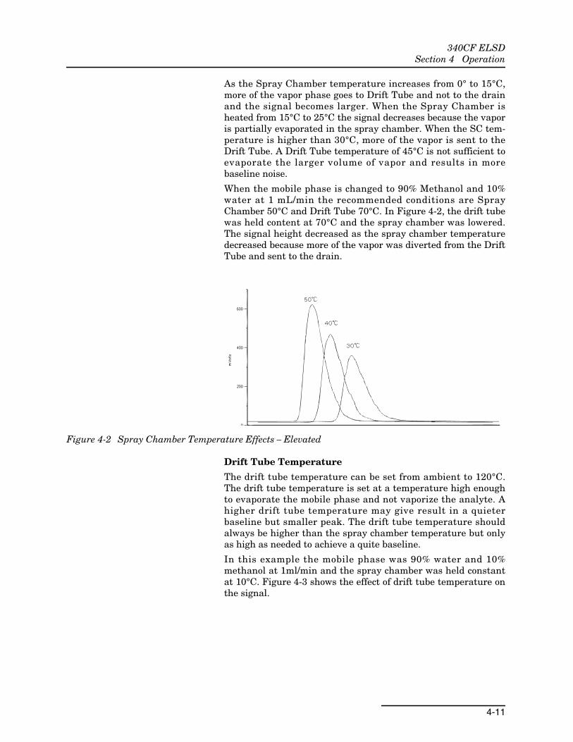
As the Spray Chamber temperature increases from 0° to 15°C,more of the vapor phase goes to Drift Tube and not to the drainand the signal becomes larger. When the Spray Chamber isheated from 15°C to 25°C the signal decreases because the vaporis partially evaporated in the spray chamber. When the SC tem-perature is higher than 30°C, more of the vapor is sent to theDrift Tube. A Drift Tube temperature of 45°C is not sufficient toevaporate the larger volume of vapor and results in morebaseline noise.
When the mobile phase is changed to 90% Methanol and 10%water at 1 mL/min the recommended conditions are SprayChamber 50°C and Drift Tube 70°C. In Figure 4-2, the drift tubewas held content at 70°C and the spray chamber was lowered.The signal height decreased as the spray chamber temperaturedecreased because more of the vapor was diverted from the DriftTube and sent to the drain.
Figure 4-2 Spray Chamber Temperature Effects – Elevated
Drift Tube Temperature
The drift tube temperature can be set from ambient to 120°C.The drift tube temperature is set at a temperature high enoughto evaporate the mobile phase and not vaporize the analyte. Ahigher drift tube temperature may give result in a quieterbaseline but smaller peak. The drift tube temperature shouldalways be higher than the spray chamber temperature but onlyas high as needed to achieve a quite baseline.
In this example the mobile phase was 90% water and 10%methanol at 1ml/min and the spray chamber was held constantat 10°C. Figure 4-3 shows the effect of drift tube temperature onthe signal.

340CF ELSDSection 4 Operation
4-12
Figure 4-3 Drift Tube Temperature Effects
The effect of temperature on signal between 45°C and 50°C issmall, but as the drift tube temperature increased above 60°Cthe signal height decreased.
A drift tube temperature setting that is too high could vaporizethe analyte and cause a loss of sensitivity. If the analyte is ther-mally labile, use a lower temperature to improve sensitivity.However, there will be a point where the temperature is not highenough to evaporate the mobile phase and the increase in noisewill negate the increase in signal. Optimize for the best signal tonoise ratio.
Mobile Phase Flow rate
Mobile phase flowrate will also affect the optimum temperatureset point. The higher the flowrate of an aqueous mobile phase,the lower the spray chamber temperature will need to be. Highflowrates of volatile mobile phases may require a higher drifttube temperature. The ELSD may perform best at sub-ambientspray chamber temperatures if the flowrate is extremely high,even for volatile mobile phases.
Gradient Separations:Suggested Operating Temperatures
For gradient separations, select the system temperaturesrequired for the least volatile segment of the gradient program.
4.3 Operating Modes The ELSD normally operates in automatic mode. A manual modeto run the pump remotely is available, however (refer toSection 3.2.4). To switch operating modes:
1. Press MENU|POWER until you reach [TIMER PAGE].
2. Use the arrow keys to scroll to [CONTROL PAGE].
3. Press MENU|POWER.
4. Use the arrow keys to scroll to [SETUP PUMP CONTROLMODE].
5. Press MENU|POWER.
6. Use an arrow key to toggle between AUTO and MANUAL.

340CF ELSDSection 4 Operation
4-13
7. Press MENU|POWER to return to the home screen.If temperature setpoints are reentered or operating conditionschange, the pump stops automatically in either mode. The screenwill display the message NOT READY. Press MENU|POWER todisplay information about why the pump stopped.
4.3.1 Automatic Operation(Default)
In automatic mode, the pump will not run until all temperaturesetpoints are met and gas pressure is correct. When all operatingconditions are met or restored, the pump automatically activates.
4.3.2 Manual Operation In manual mode, when all operating conditions are met orrestored, the screen will display the message ALMOST READY andprompt you to press AUTOZERO to restart the pump.
4.4 Mobile PhaseConsiderations
Selecting a Solvent
High purity mobile phase solvents with low boiling points arerecommended for use with the ELSD. Solvents should be spectralor HPLC grade. Dirty or contaminated solvents will causebaseline noise and drift, blocked fluid paths, and a build up inthe detector. All solvents used should have less than 1ppm ofresidue after evaporation and filtered to less than 0.45µm. Sol-vents can be evaluated by pumping them directly into thedetector, and comparing the noise to other known solvents. Wehave found that not all HPLC grade solvents are acceptable foruse with an ELSD. Preservatives commonly used in Tetrahydro-furan (THF), will increase the noise level. If unstabilized THF isused, ensure that it is fresh. THF can contain peroxides that canincrease noise and are potentially explosive if taken to dryness.
Mobile Phase Flowrate and Composition
The recommended flowrate for the ELSD is 0.25mL/min to3mL/min. The mobile phase flowrate will affect baseline noise. Ingeneral, more baseline noise will be generated by higher flowrateof a mobile phase.
The ELSD will operate with common HPLC solvents that are vol-atile enough to form a vapor under the operating conditions. Thisincludes common HPLC solvents such as water, methanol, aceto-nitrile, acetone, isopropyl alcohol, and THF. Normal phase sol-vents such as dichloromethane and hexane may also be used.Note that solvents with higher boiling points will generallyresult in more baseline noise. These should be used in limitedpercentages or at a lower flowrates.
Buffer Compatibility
The ELSD is not compatible with mobile phase modifiers thatare not volatile, such as salts. Some modifiers are volatile andcan be used. These include but are not limited to acetic acid, tri-fluoroacetic aid (TFA), formic acid, triethylamine, and ammonia.The concentration of buffer in the mobile phase should be as lowas possible.

340CF ELSDSection 4 Operation
4-14
Column Pre-Treatment
Chromatographic columns may introduce particles into themobile phase, which may lead to increased noise and blockedfluid paths. It is recommended that the chromatographic columnbe flushed with at least 10 column volumes before it is connectedto the ELSD.
4.5 Default Method The ELSD’s default method (Method 0) is factory-set with runparameters that typically produce optimal sensitivity across abroad range of solvent types.
Spray Chamber (SC): 35 °C
Drift Tube (DT): 45 °C
Filter (FLT): 5
Calibration (CL): 20%
Gain (GX): PREP
Full Scale (FS): 5V

Compliance Statements
DECLARATION OF CONFORMITY
Application of Council Directive: 2004/108/EC -The EMC Directive 2002/96/EC – The WEEE Directive 73/23/EEC – The Low Voltage Directive
Manufacturer's Name: Teledyne Isco, Inc.
Manufacturer's Address:
4700 Superior, Lincoln, Nebraska 68504 USA Mailing Address: P.O. Box 82531, Lincoln, NE 68501
Equipment Type/Environment: Laboratory Equipment for Light Industrial/Commercial Environments
Trade Name/Model No: 330 ELSD or 340CF ELSD
Year of Issue: 2010
Standards to which Conformity is Declared: EN 61010-1 2nd edition Safety Requirements for Electrical Equipment for Measurement, Control, and Laboratory Use
EN 61326-1:2006 EMC Requirements for Electrical Equipment for Measurement, Control, and Laboratory Use
Standard Description Severity Applied Performance Criteria
EN61000-4-2 Electrostatic Discharge Level 2 - 4kV contact discharge Level 3 - 8kV air discharge
A
EN61000-4-3 Radiated RF Immunity 80 MHz to 2.7Ghz 80% AM at 1kHz Level 2 - 3V/m
A
EN61000-4-4 Electrical Fast Transient Level 2 - 1kV on AC lines A
EN61000-4-5 Surge on AC Lines Level 2 - 1kV common mode, Level 2 - 0.5KV differential mode
A
EN61000-4-6 Conducted RF on AC lines 150 kHz to 80 MHz, Level 1 - 1V rms, 80% modulated
A
EN61000-4-11 Voltage Dips/Interruptions 0% during half cycle A
CISPR11/ EN 55011
RF Emissions Group 1, Class A Industrial, Scientific, and Medical Equipment
N/A
EN61000-3-2, 3-3 Harmonic, Flicker N/A N/A
The undersigned, hereby declares that the design of the equipment specified above conforms to the above Directive(s) and Standards
as of November 1, 2010. USA Representative
William Foster Vice President of Engineering
60-5242-065


Warranty
Teledyne Isco One Year Limited Factory Service Warranty* This warranty exclusively covers Teledyne Isco
instruments, providing a one-year limited warranty
covering parts and labor.
Any instrument that fails during the warranty period due to
faulty parts or workmanship will be repaired at the factory
at no charge to the customer. Teledyne Isco’s exclusive
liability is limited to repair or replacement of defective
instruments. Teledyne Isco is not liable for consequential
damages.
Teledyne Isco will pay surface transportation charges both
ways within the 48 contiguous United States if the
instrument proves to be defective within 30 days of
shipment. Throughout the remainder of the warranty period,
the customer will pay to return the instrument to Teledyne
Isco, and Teledyne Isco will pay surface transportation to
return the repaired instrument to the customer. Teledyne
Isco will not pay air freight or customer’s packing and
crating charges. This warranty does not cover loss, damage,
or defects resulting from transportation between the
customer’s facility and the repair facility.
The warranty for any instrument is the one in effect on date
of shipment. The warranty period begins on the shipping
date, unless Teledyne Isco agrees in writing to a different
date.
Excluded from this warranty are normal wear; expendable
items such as charts, ribbon, lamps, tubing, and glassware;
fittings and wetted parts of valves; and damage due to
corrosion, misuse, accident, or lack of proper maintenance.
This warranty does not cover products not sold under the
Teledyne Isco trademark or for which any other warranty is
specifically stated.
No item may be returned for warranty service without a
return authorization number issued by Teledyne Isco.
This warranty is expressly in lieu of all other warranties
and obligations and Teledyne Isco specifically disclaims
any warranty of merchantability or fitness for a
particular purpose.
The warrantor is Teledyne Isco, 4700 Superior, Lincoln, NE
68504, U.S.A.
* This warranty applies to the USA and countries where Teledyne Isco does not have an authorized dealer.
Customers in countries outside the USA, where Teledyne Isco has an authorized dealer, should contact their
Teledyne Isco dealer for warranty service.
Before returning any instrument for repair, please call, fax, or e-mail the Teledyne Isco Service Department for instructions. Many problems can often be diagnosed and corrected over the phone, or by e-mail, without returning the instrument to the factory. Instruments needing factory repair should be packed carefully, and shipped to the attention of the service department. Small, non-fragile items can be sent by insured parcel post. PLEASE BE SURE TO ENCLOSE A NOTE EXPLAINING THE PROBLEM.
Shipping Address: Teledyne Isco - Attention Repair Service 4700 Superior Street Lincoln, NE 68504 USA
Mailing Address: Teledyne Isco PO Box 82531 Lincoln, NE 68501 USA
Phone: Repair service: (800) 775-2965 (lab instruments) (866) 298-6174 (samplers & flow meters)
Sales & General Information: (800) 228-4373 (USA & Canada) Fax: (402) 465-3001 Email: [email protected]
February 28, 2012 P/N 60-1002-040 Rev G
