3.5 differential equilibrium relationship
TRANSCRIPT

446.201A (Solid Mechanics) Professor Youn, Byeng Dong
Ch. 3 Forces and Moments Transmitted by Slender Members 1 / 16
3.5 Differential Equilibrium Relationship à The conditions of equilibrium combined with a limiting process will lead us to differential equations connecting the load, the shear force, and the bending moment.
à Integration of these relationships for particular cases furnishes us with an alternative method for evaluating shear forces and bending moments.
446.201A (Solid Mechanics) Professor Youn, Byeng Dong
Ch. 3 Forces and Moments Transmitted by Slender Members 2 / 16
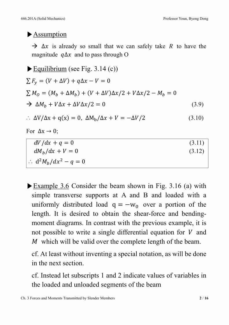
▶Assumption
à ∆ is already so small that we can safely take to have the magnitude ∆ and to pass through O
▶Equilibrium (see Fig. 3.14 (c)) ∑ = ( + ∆) + ∆ − = 0 ∑ = ( + ∆) + ( + ∆)∆/2 + ∆/2 − = 0
à ∆ + ∆ + ∆∆/2 = 0 (3.9)
∴ ∆V/∆x + q(x) = 0, ∆M/∆ + = −∆/2 (3.10)
For ∆x → 0; / + = 0 (3.11) / + = 0 (3.12)
∴ d/ − = 0
▶Example 3.6 Consider the beam shown in Fig. 3.16 (a) with simple transverse supports at A and B and loaded with a uniformly distributed load q = −w over a portion of the length. It is desired to obtain the shear-force and bending-moment diagrams. In contrast with the previous example, it is not possible to write a single differential equation for and which will be valid over the complete length of the beam.
cf. At least without inventing a special notation, as will be done in the next section.
cf. Instead let subscripts 1 and 2 indicate values of variables in the loaded and unloaded segments of the beam

446.201A (Solid Mechanics) Professor Youn, Byeng Dong
Ch. 3 Forces and Moments Transmitted by Slender Members 3 / 16
▷For 0 < x < a / − = 0
à − = / + + = 0
à + (1/2) + =

446.201A (Solid Mechanics) Professor Youn, Byeng Dong
Ch. 3 Forces and Moments Transmitted by Slender Members 4 / 16
▷For a < x < L / = 0
à = / + = 0
à + =
▷B.C.
i) (0) = 0
ii) () = 0
iii) = , =
iv) x = a, =
∴ = (1/2)( + )/ = (1/2)()/ = 0, = (1/2)
∴ = − (1/2)( + )/ (0 ≤ x ≤ a) = (1/2)/ (a ≤ x ≤ L) = (1/2)( + )/ − (1/2)w (0 ≤ x ≤ a) = (1/2) − (1/2)/ (a ≤ x ≤ L)
à Clearly if the loading requires separate representations for a number of segments each with its own differential equation form, it becomes very awkward to carry along the additional arbitrary constants which are later eliminated by matching the V’s and M’s at the junctions of the segments.
3.6 Singularity Function à We have seen that the procedure just outlined becomes fairly

446.201A (Solid Mechanics) Professor Youn, Byeng Dong
Ch. 3 Forces and Moments Transmitted by Slender Members 5 / 16
cumbersome unless a special mathematical apparatus is available to handle discontinuous loadings. This section introduces a family of singularity functions specifically designed for this purpose. Figure 3.17 shows five members of the family.
▶() =< − >= 0( − ) ≤ ≥ (3.15)
(where, n = 0, 1, 2, 3, ⋯ )
▶() =< − >= 0±∞ ≠ =
(where, n = −1, −2, −3, ⋯ )
& ∫ < − > =< − >/( + 1) (3.16)
cf. () =< − >= ( − ) < − >
< − > =< − > ∫ < − > =< − > (3.17)
< − > is called the unit concentrated load or the unit impulse function, which is also known as the Dirac delta function. < − > is called the unit concentrated moment or the unit doublet function.

446.201A (Solid Mechanics) Professor Youn, Byeng Dong
Ch. 3 Forces and Moments Transmitted by Slender Members 6 / 16

446.201A (Solid Mechanics) Professor Youn, Byeng Dong
Ch. 3 Forces and Moments Transmitted by Slender Members 7 / 16
▶Example 3.7 We consider the problem studied in Example 3.6 again, but we shall utilize the singularity functions.
à Fully aware of the cases ① and ②. Case ② is more powerful than case ①.

446.201A (Solid Mechanics) Professor Youn, Byeng Dong
Ch. 3 Forces and Moments Transmitted by Slender Members 8 / 16
① Solve by calculating the support reactions separately (When the problem requires the maximum shear force and moment) () = − + < − > (a) () = − < − >+ (b)
B.C.) (0) = = −
From ∑ = 0; − = − ( + /2) (c)
∴ = −/2 + < − >+ ( + /2) + (d)
B.C.) (0) = 0;
∴ = 0
② Solve by putting the support reactions into the unknown constants (When the problem requires the support reactions) () = ⟨⟩ − ⟨⟩ + ⟨ − ⟩ + ⟨ − ⟩ (e)
Since (−∞) = 0, −() = ∫ = ⟨⟩ − ⟨⟩ + ⟨ − ⟩ + ⟨ − ⟩ (f)
Since (−∞) = 0, () = − ∫ = ⟨⟩ − ⟨⟩ + ⟨ − ⟩ + ⟨ − ⟩ (g)
à If we make x just slightly larger than x=L, the shear force (V) and the bending moment (Mb) should vanish, that is, = − + ( − ) + = 0 à Shear force balance = − + ( − ) = 0 à Bending moment balance

446.201A (Solid Mechanics) Professor Youn, Byeng Dong
Ch. 3 Forces and Moments Transmitted by Slender Members 9 / 16
à R =
cf. The satisfaction of the equilibrium requirements for every differential element of the beam implies satisfaction of the equilibrium requirements of the entire beam.
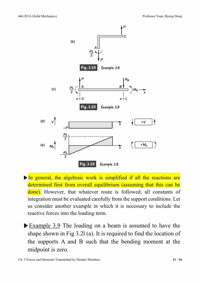
▶Example 3.8 In Fig. 3.20 (a) the frame is built-in at and subjected to a load at . It is desired to obtain shear-

446.201A (Solid Mechanics) Professor Youn, Byeng Dong
Ch. 3 Forces and Moments Transmitted by Slender Members 10 / 16
force and bending-moment diagrams for the segment .
Sol) Since there is no loading between A and B, () = 0
∴ from / + = 0;
∴ () = (a)
where = − because of the assumed concentrated force at A.
Integrating again using dM/ + = 0 we find () = + (b)
Now, (0) = −/2
∴ = −/2
∴ () = −
() = − /2
446.201A (Solid Mechanics) Professor Youn, Byeng Dong
Ch. 3 Forces and Moments Transmitted by Slender Members 11 / 16
▶In general, the algebraic work is simplified if all the reactions are determined first from overall equilibrium (assuming that this can be done). However, that whatever route is followed, all constants of integration must be evaluated carefully from the support conditions. Let us consider another example in which it is necessary to include the reactive forces into the loading term.
▶Example 3.9 The loading on a beam is assumed to have the shape shown in Fig 3.2l (a). It is required to find the location of the supports A and B such that the bending moment at the midpoint is zero.

446.201A (Solid Mechanics) Professor Youn, Byeng Dong
Ch. 3 Forces and Moments Transmitted by Slender Members 12 / 16
Sol) = = /2 (a)
Here, = ∫ () = ∫ sin = 2/ (b)
∴ () = − sin + ⟨ − ⟩ + ⟨ − ( − )⟩ (c)
à () = − cos − ⟨ − ⟩ − ⟨ − ( − )⟩ + (d)
B.C.) (0) = 0 à = / (e) = − − sin + ⟨ − ⟩ + ⟨ − ( − )⟩ + (f)
B.C.) (0) = 0 à = 0
cf. will vanish at = /2 if = /.

446.201A (Solid Mechanics) Professor Youn, Byeng Dong
Ch. 3 Forces and Moments Transmitted by Slender Members 13 / 16
3.7 Fluid Force In many applications structural components are subjected to forces due to fluids in contact with the structure.
à In a liquid at rest the pressure at a point is the same in all directions.
▶A simple equilibrium consideration for a fluid under the action of gravity as shown in Fig 3.22.

446.201A (Solid Mechanics) Professor Youn, Byeng Dong
Ch. 3 Forces and Moments Transmitted by Slender Members 14 / 16
∆ + ∆∆ − ( + ∆)∆ = 0
In the limit, dp/dz = γ
B.C.) if = at = 0 = +
∴ Fluid pressure acts normal to a surface and is a linear function of depth.
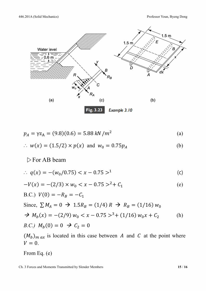
▶Example 3.10 Fig. 3.23 shows a 1.5-m-square gate which is retaining the water at half the length of the gate as shown. If it is assumed that the total pressure load on the gate is transmitted to the supports at , , , and by means of symmetrically located simply supported beams AB and DE, find the maximum bending moment in the beams. The bottom edge DA of the gate is 0.6 m below the water line, and = 9.8 /.
446.201A (Solid Mechanics) Professor Youn, Byeng Dong
Ch. 3 Forces and Moments Transmitted by Slender Members 15 / 16
= γz = (9.8)(0.6) = 5.88 / (a)
∴ () = (1.5/2) × () and = 0.75 (b)
▷For AB beam
∴ () = −(/0.75) < − 0.75 > (c) −() = −(2/3) × < − 0.75 >+ (e)
B.C.) (0) = − = −
Since, ∑ = 0 à 1.5 = (1/4) à = (1/16)
à () = −(2/9) < − 0.75 >+ (1/16) + (h)
B.C.) (0) = 0 à = 0 () is located in this case between and at the point where = 0.
From Eq. (e)

446.201A (Solid Mechanics) Professor Youn, Byeng Dong
Ch. 3 Forces and Moments Transmitted by Slender Members 16 / 16
() = 0 = (4.41)⟨ − 0.75⟩ − (4.41)
∴ = 1.056
à () = 319 ∙