3501b ez slide - frank's hospital workshop€¦ · page 3 3501b ez slide general purpose...
TRANSCRIPT

SURGICAL TABLE
3501B EZ SLIDE
OPERATORS MANUAL
1/07


Page 1
1/07
Although current at the time of publication, SKYTRON’s policy of continuous development makes thismanual subject to change without notice.
TABLE OF CONTENTS
Title Page
EQUIPMENT LABELS AND SPECIFICATIONS................................................................................... 2
3501B E-Z Slide General Purpose Surgical Table Specifications ........................................................ 3
SPECIAL USER ATTENTION............................................................................................................... 4
SECTION I INTRODUCTION............................................................................................................... 101-1. General ................................................................................................................................ 101-2. Power Requirements ........................................................................................................... 101-3. Pendant Control Unit ........................................................................................................... 111-4. Floor Lock/Brake System ..................................................................................................... 11
SECTION II OPERATION .................................................................................................................... 122-1. Electrical Power ................................................................................................................... 122-2. AC 120V Operation .............................................................................................................. 122-3. Battery Operation ................................................................................................................. 132-4. Automatic Shut-Off .............................................................................................................. 132-5. Charging the Battery ............................................................................................................ 142-6. Positioning Functions ........................................................................................................... 15
a. Floor Lock/Brake system ................................................................................................. 15b. Trendelenburg ................................................................................................................. 16c. Lateral Tilt ........................................................................................................................ 16d. Back Section ................................................................................................................... 17e. Elevation .......................................................................................................................... 17f. Top Slide ......................................................................................................................... 18g. Leg Section ..................................................................................................................... 18h. Flex Positioning ............................................................................................................... 19i. Kidney Lift ........................................................................................................................ 19j. Return To Level ............................................................................................................... 20
2-7. Emergency Back-up controls ............................................................................................... 212-8. Emergency Brake Release .................................................................................................. 222-9. Head Section ....................................................................................................................... 222-10. Leg and Back Section Removal ........................................................................................... 23
SECTION III MAINTENANCE .............................................................................................................. 263-1. Preventive Maintenance ...................................................................................................... 263-2. Cleaning Recommendations ................................................................................................ 263-3. Service ................................................................................................................................. 27

Page 2
3501B EZ SLIDE EQUIPMENT LABELS
15
14
13
12 1110
87
9
6
5
3
21
1
1514
131211
1098
7
654
32
POSSIBLE EXPLOSION HAZARD
IF USED IN THE PRESENCE OF
FLAMMABLE ANESTHETICS.
DANGER
Grounding reliability can only be achieved whenthe equipment is connected to an equivalentreceptacle marked "Hospital Only" or "Hospital Grade"
DANGER - EXPLOSION HAZARD. DO NOT USE INTHE PRESENCE OF FLAMMABLE ANAESTHETICS
DANGER - RISQUE D'EXPLOSION. NE PASEMPLOYER EN PRESENCE D'ANESTHESIQUESINFLAMMABLES
Table Capacity:Lift 700 lbs.Articulate 600 lbs.
See OperatorsManual for Limitations.
THIS PRODUCT COMPLIES WITH RADIA-TION PERFORMANCE STANDARD 21 CFRAT THE TIME OF MANUFACTURE
Manufactured:
Model No.
WARNINGUSE HEAD SECTION AS FOOT EXTENSION ONLY - WHEN REVERSING PATIENT ON TABLE REFER TO OPERATOR MANUAL.
DO NOT SIT ON END OF LEG SECTION(S) AS LOADSIN EXCESS OF 140 LBS, MAY CAUSE INSTABILITYTHAT COULD CAUSE THE TABLE TO BE TIPPED OVER.
WARNING
4
4
16
16 TWIST TO LOCK OR RELEASE PLUG
D6-035-38D3-035-60 right D3-035-61 left
D6-032-47 D6-032-46
D6-017-05
D6-065-26 D6-067-33D6-011-34
D6-011-32 D6-031-43 D6-065-22
D6-034-21 D6-065-21 D6-067-27
L1-010-00

Page 3
3501B EZ Slide General Purpose Surgical Table Specifications
Electrical Specifications
Power requirements
Current Leakage
Power Cord
120 VAC, 60Hz, 450 Watts
Less than 100 micro amps
15 feet w/hospital grade connector (removable)
12-1/2" 18-1/4" 25" 23"
14-1/2"
19-3/4"
5-1/2"
3"
83"
TOP VIEW
90˚
60˚
14-1/2"
40-1/2"
SIDE VIEW
8-1/2"
6"
19"
21-3/4"
45" MAX26" MIN
END VIEW
ENTELA CERTIFIED
TO UL2601-1
CAN/CSA601.1, IEC 60601-2-46

Page 4
Prior to use, all personnel that may operate thistable must be instructed in the correct opera-tional procedures. This table is designed foruse by trained and qualified personnel for hu-man medical purposes only.
Initial use should not begin until after the usershave been instructed by the manufacturer'srepresentative.
A routine instructional program must be imple-mented by the facility for proper usage instruc-tions for all personnel that may operate thistable.
The maximum lifting capacity of the 3501BEZ Slide table is 700 pounds and the maximumarticulation weight capacity is 600 pounds.When lifting or articulating large patients, payclose attention to the patient position as well asthe positioning guidelines and limitations listedin the operation instructions.
The extreme positioning capabilities of the 3501BE-Z Slide Table requires special attention for pos-sible interference points when using multiple func-tion positioning. As with the operation of anysurgical table, a certain amount of care should beexercised to position the patient safely. Althoughthe thick pads and sheets substantially protect thepatient, pinch points, located at the joints of the topsection should always be considered. BE SURETHAT THE ARMS, HANDS AND FINGERS OFTHE PATIENT AND THOSE OF THE OPERAT-ING ROOM PERSONNEL ARE CLEAR OF ALLMOVING PARTS BEFORE MOVING THE TABLE.Proper restraints should always be used for patientsafety.
Certain accessories such as the Uro-Drain Tray,Armboards and X-Ray top can be damaged whenchanging the position of the table top sections.Always look first to see if a desired movement isgoing to interfere with any accessories in use.
The operator has the ultimate responsibility ofpreventing damage to the table and surroundingequipment or possible injury to the patient or staff.
The operator must ensure proper positioning ismaintained to prevent compromising respiration,nerve pathways or circulation.
In general, common sense will dictate when thereis a potential hazard.
The following precautions should be reviewedby all personnel prior to operating the table.
WARNING
Indicates a possibility of personal injury.
CAUTION
Indicates a possibility of damage toequipment.
NOTEIndicates important facts or helpful hints.
Do not use worn or damaged accessories, theyrepresent an injury hazard.
Remove possible obstacles before lowering ortilting the operating table
SPECIAL USER ATTENTION
Do not place objects on the base of the table, adanger of damage exists during positioning.
Use caution when articulating the table top, pinchhazards exist.

Page 5
NOTE
Activating any function button will acti-vate the brake system. Using the TABLEUP function to set the brakes providesa visual assurance that the brakes arelocked without altering the table posi-tion, except when emergency brake isreleased.
WARNING
Prior to operating the table, observeall table caution labels and review theSPECIAL USER ATTENTION sectionin the front of this manual.
WARNING
Possible explosion hazard exists if tableis used in the presence of FLAMMABLEANESTHETICS.
NOTE
An equalization terminal is located un-der the main power panel. This is pro-vided as an alternate pathway to re-duce the risk of static shock hazards.Always follow recommended ground-ing procedures to ensure patient andstaff safety.
NOTE
The table will operate correctly on bat-tery power with the power cord con-nected to a wall outlet or disconnected.
NOTE
Battery Operation must be turned OFFat the pendant control. It cannot beturned OFF using the main powerswitch.
NOTE
Turning the Main Power Switch ON willchange the table operation to 120 VACpower.
NOTE
When the red light starts to blink (indi-cating low power in battery) the tablewill operate for approximately 5 con-tinuous minutes, typically long enoughto use the table for the rest of the day.
NOTE
The charging system operates ONLYwhen the table is in AC120V operationmode.
NOTE
The table can be operated on 120VACpower while the battery is being re-charged.
NOTE
If the table is stored for a period greaterthan 6 months, the batteries should beremoved and stored in a dry, clean con-dition at a storage temperature of 68° F(20° C). Batteries should be rechargedevery 6 months of product storage.
SPECIAL USER ATTENTION

Page 6
WARNING
•DO NOT unlock brakes when a patientis on the table. An uneven patientweight load may cause instability.
•If circumstances demand table brakesto be unlocked, the patient must becentered and evenly distributed on thetable top (i.e. supine or prone position)with the table lowered to its lowestheight position. The maximum patientweight should not exceed 500 pounds.Table top slide must be centered (indi-cated by a red LED light on the pendantcontrol) prior to unlocking brakes.Patient's head must be on the headsection. Head section must be attachedin its normal orientation to the table'sback section.
•Prior to unlocking brakes, check forobstructions on the floor that mightprevent the table from moving smoothlyto new location. Relock the brakes im-mediately once the final position isreached and before commencing sur-gery. Table brakes should remain lockedat all times if patient weight exceeds500 pounds.
NOTE
With an evenly distributed patient weightload, all table positioning functions willoperate smoothly and quietly with apatient weight of up to 600 pounds(700 pounds lift).
WARNING
To maximize patient safety, utilizeproper restraint methods during extremeTrendelenburg positioning.
WARNING
To maximize patient safety, utilizeproper restraint methods during extremelateral tilt positioning.
NOTE
If the table top is slid toward the footend, the back section will not go belowhorizontal. An audible alarm will sound.
NOTE
To prevent damage to the kidney lift, asafety interlock prevents the back sec-tion from going more than 45° abovehorizontal if the kidney lift is not all theway down. An audible alarm will sound.
NOTE
If the leg section is positioned morethan 45° below horizontal, the top willnot slide toward the head end. Anaudible alarm will sound.
NOTE
If the back section is positioned belowhorizontal, the top will not slide towardthe foot end. An audible alarm willsound.
CAUTION
The Leg section may hit the table baseor the floor if both the leg and elevationsystems are placed in their full downposition.
SPECIAL USER ATTENTION

Page 7
CAUTION
The EMERGENCY BRAKE LOCKswitch does not activate the brake sys-tem timer. The switch must be helduntil the brakes are completely locked,approximately 10 seconds.
NOTE
The emergency back-up controlswitches will function when the table isoperating on 120VAC power, batterypower, or turned off.
WARNING
•DO NOT unlock brakes when a patientis on the table. An uneven patientweight load may cause instability.
•If circumstances demand table brakesto be unlocked, the patient must becentered and evenly distributed on thetable top (i.e. supine or prone position)with the table lowered to its lowestheight position. The maximum patientweight should not exceed 500 pounds.Table top slide must be centered (indi-cated by a green LED light on thependant control) prior to unlockingbrakes. Patient's head must be on thehead section. Head section must beattached in its normal orientation to thetable's back section.
•Prior to unlocking brakes, check forobstructions on the floor that mightprevent the table from moving smoothlyto new location. Relock the brakes im-mediately once the final position isreached and before commencing sur-gery. Table brakes should remain lockedat all times if patient weight exceeds500 pounds.
NOTE
If the top is slid toward the head end theleg section will only go down 45°. Anaudible alarm will sound.
NOTE
When FLEX button is activated and ifthe top is slid toward the foot end, theback section will not go below horizon-tal. An audible alarm will sound.
NOTE
Return to Level will lower the kidney lift.
NOTE
To prevent damage to the kidney lift, asafety interlock prevents the kidney liftfrom going up if the back section is 45°above horizontal. An audible alarm willsound .
NOTE
Elevation and brake system functionsare not affected by the return to levelfunction.
CAUTION
The safety interlock system is not op-erational when the emergency back-up control switches are used.
SPECIAL USER ATTENTION

Page 8
NOTE
The Emergency Brake Release Valvemust be closed and tightened (clock-wise) before activating any function.
•If the Emergency Brake Release Valvehas been operated, the UNLOCK buttonon the pendant control will have to bepressed before brakes will lock again.
WARNING
Consult manufacturer's instructionswhen using high frequency surgicalequipment, cardiac defibrillator and car-diac defibrillator monitors.
WARNING
When an antistatic pathway is required,the table has to be used on an antistaticfloor.
WARNING
The antistatic properties of the tableare dependent on the use of the originalpad set which was furnished with thetable or an alternate approved replace-ment.
SPECIAL USER ATTENTION
WARNING
Certain accessories may limit weightcapacities. Check with your SKYTRONrepresentative.
CAUTION
Consult SKYTRON prior to using ac-cessories produced by other manufac-turers.
NOTE
Always follow current AORN JournalGuidelines to ensure proper cleaningand disinfection procedure.
WARNING
Always follow OSHA blood-borne patho-gens standards for protective clothing,including gloves, masks and eye pro-tection when cleaning the surgical table.
CAUTION
Thoroughly read and follow themanufacturer's directions for all clean-ing fluids. DO NOT use cleaners con-taining phenolics.

Page 9
CAUTION
When using spray cleaners DO NOTspray fluids directly into electrical re-ceptacles or micro switches.
CAUTION
Before replacing pads on the table, makesure the pads and all mating surfacesare completely dry. Moisture trappedbetween the pads and mating surfacesmay cause distortion of table tops.
WARNING
SKYTRON assumes no liability for tableperformance, table damage or injury topatient or staff when accessories notsold or serviced by SKYTRON areused on SKYTRON surgical tables.

Page 10
main power ON/OFF switch is located on theelectrical panel on the front edge of the table base.See figure 1-2.
The battery charging indicator and an optional footcontrol connector are also located on the electricalpanel.
Figure 1-1. 3501B EZ Slide
1-1. General
SKYTRON’s 3501B EZ Slide Surgical Table is anelectro-hydraulically operated, general purpose sur-gical table. See figure 1-1.
The electro-hydraulic positioning functions oper-ated by the hand-held, push button, pendant con-trol unit are: Trendelenburg, lateral tilt, back sec-tion, elevation, leg section, top slide, flex/reflex,kidney lift, return to level and the floor lock/brakesystem.
Manual controls are provided for head sectionpositioning, emergency brake release and leg sec-tion removal.
1-2. Power Requirements
The 3501B EZ Slide Surgical Table requires a120VAC, 60 Hz electrical power supply. The tableis equipped with a removable 15 foot long powercord with a three prong, hospital grade plug. The
SECTION I INTRODUCTION
Figure 1-2. Electrical Panel
MAIN POWERSWITCH
BATTERYINDICATOR
OPTIONALFOOT CONTROL
CONNECTORPOWERCORD
REMOVABLELEG SECTIONSEAT
SECTIONREMOVABLE
BACK SECTIONHEADSECTION
SIDERAIL
HEAD SECTIONLOCKING KNOB
SERVICEACCESS COVER
POWERCORD
MAIN POWERSWITCH
EMERGENCYBRAKE RELEASE
FLOOR/LOCKBRAKE (4)
PENDANTCONTROL
LEG SECTIONRELEASE LEVER

Page 11
1-3. Pendant Control Unit
The hand-held pendant control unit (figure 1-3)has a non-slip rubber cover which assures a posi-tive grip during use. A spring clip hanger is locatedon the back of the control for storage. When thePendant Control is not in use, it should be stored ona convenient side or end rail.
Figure 1-3. Pendant Control Unit
The function push buttons are identified with abbre-viated descriptions for all functions. See figure1-4. When illuminated the Trendelenburg andtable up buttons are red, the remaining buttons areall green.
Figure 1-4. Function Buttons
1-4. Floor Lock/Brake System
The floor lock/brake system consists of four self-leveling, hydraulic brake cylinders which raise andsupport the table base off from the casters. Pressthe TABLE UP button on the pendant control to setthe table’s brakes. An electronic timer will activatethe brake system until the brakes are completelyset, approximately 8-10 seconds.
NOTE
Activating any function button will acti-vate the brake system. Using the TABLEUP function to set the brakes providesa visual assurance that the brakes arelocked without altering the table posi-tion, except when emergency brake isreleased.
POWERINDICATOR
FUNCTIONBUTTONS
SIDE RAILCLIP
AC120V POWER ONINDICATOR LIGHT
(GREEN)
TABLE UP(BRAKE LOCK)
LATERALTILT LEFT
BACK UP
LEG UP
SLIDE HEAD
FLEX
KIDNEYLIFT UP
RETURNTO LEVEL
BATTERY
LATERALTILT RIGHT
BACK DOWN
TABLE DOWN
LEG DOWN
SLIDE FOOT
REFLEX
KIDNEYLIFT DOWN
BRAKEUNLOCK
REVERSETRENDELENBURG
TRENDELENBURG
Page 12
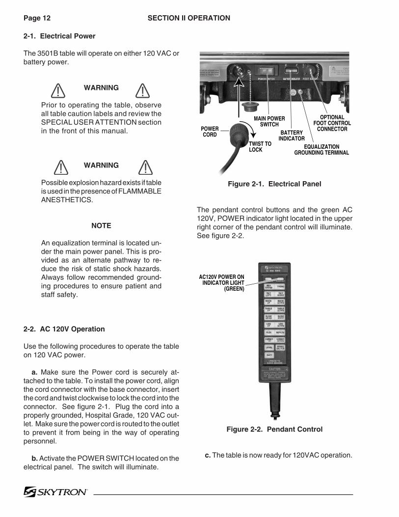
2-1. Electrical Power
The 3501B table will operate on either 120 VAC orbattery power.
WARNING
Prior to operating the table, observeall table caution labels and review theSPECIAL USER ATTENTION sectionin the front of this manual.
WARNING
Possible explosion hazard exists if tableis used in the presence of FLAMMABLEANESTHETICS.
NOTE
An equalization terminal is located un-der the main power panel. This is pro-vided as an alternate pathway to re-duce the risk of static shock hazards.Always follow recommended ground-ing procedures to ensure patient andstaff safety.
2-2. AC 120V Operation
Use the following procedures to operate the tableon 120 VAC power.
a. Make sure the Power cord is securely at-tached to the table. To install the power cord, alignthe cord connector with the base connector, insertthe cord and twist clockwise to lock the cord into theconnector. See figure 2-1. Plug the cord into aproperly grounded, Hospital Grade, 120 VAC out-let. Make sure the power cord is routed to the outletto prevent it from being in the way of operatingpersonnel.
b. Activate the POWER SWITCH located on theelectrical panel. The switch will illuminate.
SECTION II OPERATION
Figure 2-1. Electrical Panel
The pendant control buttons and the green AC120V, POWER indicator light located in the upperright corner of the pendant control will illuminate.See figure 2-2.
MAIN POWERSWITCH
TWIST TOLOCK
BATTERYINDICATOR
POWERCORD
EQUALIZATIONGROUNDING TERMINAL
OPTIONALFOOT CONTROL
CONNECTOR
Figure 2-2. Pendant Control
c. The table is now ready for 120VAC operation.
AC120V POWER ONINDICATOR LIGHT
(GREEN)

Page 13
2-3. Battery Operation
a. Make sure the Main Power Switch indicatorlight, on the electrical panel, is OFF. See figure 2-2. If the indicator light is ON, turn AC120V opera-tion OFF with the main power switch.
NOTE
The table will operate correctly on bat-tery power with the power cord con-nected to a wall outlet or disconnected.
b. Press the BATT button on the hand-heldpendant control. The pendant control buttons, thered BATTERY indicator light, located in the upperright corner of the pendant control and the BatteryIndicator on the electrical panel will illuminate.
c. The table is now ready for BATTERY opera-tion.
d. To extend the battery charge life, turn theBATTERY power OFF with the pendant controlwhen the table is not going to be used.
NOTE
Battery Operation must be turned OFFat the pendant control. It cannot beturned OFF using the main powerswitch.
2-4. Automatic Shut-Off
a. To prevent unnecessary discharge of thebattery, a timer is built into the battery circuit. Thistimer will automatically shut the battery power OFFafter 1½ hours of table inactivity.
b. To turn the table ON again, press the BATTbutton on the pendant control, the pendant controlbuttons and the red indicator light will illuminate.
NOTE
Turning the Main Power Switch ON willchange the table operation to 120 VACpower.

Page 14
b. If the battery needs to be charged whenoperating the table on battery power, the red indi-cator light on the pendant control will begin to blink.
NOTE
When the red light starts to blink (indi-cating low power in battery) the tablewill operate for approximately 5 con-tinuous minutes, typically long enoughto use the table for the rest of the day.
NOTE
The charging system operates ONLYwhen the table is in AC120V operationmode.
c. To recharge the battery, make sure the powercord is connected, plugged into a 120VAC walloutlet and the main POWER SWITCH - ON.
NOTE
The table can be operated on 120VACpower while the battery is being re-charged.
d. A full battery charge will last approximately 2weeks under normal operating conditions. How-ever, it is recommended to charge the batteries atthe end of each week to establish a normal routineprotocol. Lead acid batteries last longer if they arenot permitted to fully discharge. The table features(2) 12 volt, sealed, lead acid batteries which re-quire no manual maintenance. Lead acid gel bat-teries, under a proper charging program, featurean approximate normal life of 4 years.
NOTE
If the table is stored for a period greaterthan 6 months, the batteries should beremoved and stored in a dry, clean con-dition at a storage temperature of 68° F(20° C). Batteries should be rechargedevery 6 months of product storage.
2-5. Charging the Battery
Batteries should be charged:• When the table is placed into initialservice• As indicated by Battery Indicator• Every week under normal serviceconditions
a. Battery Indicator The Battery Indicatorconsists of ten lighted bars, 3 red, 4 yellow and 3green. See figure 2-3. Each bar represents apercentage of the battery charge condition. Whenall ten bars are illuminated, the batteries are fullycharged. The following list shows the batterycharge level as indicated by the lighted bars;
3 green 100% -Fully charged2 green 89%1 green 78%4 yellow 67%3 yellow 56%2 yellow 45% -Needs Charging (BATT
indicator on pendant will flash)1 yellow 34% -Needs Charging3 red 23% -Needs Charging
(poor performance)2 red 12% -Needs Charging
(intermittent performance)1 red 1% -Needs Charging
(inoperable)
During charging, the bars will light in sequence tothe respective charge level, turn off and light insequence again.
Figure 2-3. Battery Indicator
BATTERYINDICATOR

Page 15
Figure 2-4. Pendant Control Function Buttons
a. Floor Lock/Brake System. To activate thebrakes without affecting table positioning, pressthe TABLE UP button. See figure 2-5. Theelevation cylinder will not function until the brakesare completely extended.
2-6. Positioning Functions
The hand-held pendant control (figure 2-4) acti-vates the following table functions:
Figure 2-5. Brake System Activation
Press the BRAKE UNLOCK button on the pendantcontrol to release the four self-leveling brake feet inorder to move the table. See figure 2-5. The brakedelay circuit automatically retracts the brake sys-tem. It takes approximately 7-8 seconds to totallyrelease the system.
WARNING
•DO NOT unlock brakes when a patientis on the table. An uneven patientweight load may cause instability.
•If circumstances demand table brakesto be unlocked, the patient must becentered and evenly distributed on thetable top (i.e. supine or prone position)with the table lowered to its lowestheight position. The maximum patientweight should not exceed 500 pounds.Table top slide must be centered (indi-cated by a red LED light on the pendantcontrol) prior to unlocking brakes.Patient's head must be on the headsection. Head section must be attachedin its normal orientation to the table'sback section.
•Prior to unlocking brakes, check forobstructions on the floor that mightprevent the table from moving smoothlyto new location. Relock the brakes im-mediately once the final position isreached and before commencing sur-gery. Brake should remain locked at alltimes if patient weight exceeds 500pounds.
NOTE
With an evenly distributed patient weightload, all table positioning functions willoperate smoothly and quietly with apatient weight of up to 600 pounds(700 pounds lift).
AC120V POWER ONINDICATOR LIGHT
(GREEN)
TABLE UP(BRAKE LOCK)
LATERALTILT LEFT
BACK UP
LEG UP
SLIDE HEAD
FLEX
KIDNEYLIFT UP
RETURNTO LEVEL
BATTERY
LATERALTILT RIGHT
BACK DOWN
TABLE DOWN
LEG DOWN
SLIDE FOOT
REFLEX
KIDNEYLIFT DOWN
BRAKEUNLOCK
REVERSETRENDELENBURG
TRENDELENBURG
TABLE UP(BRAKE LOCK)
BRAKEUNLOCK
Page 16
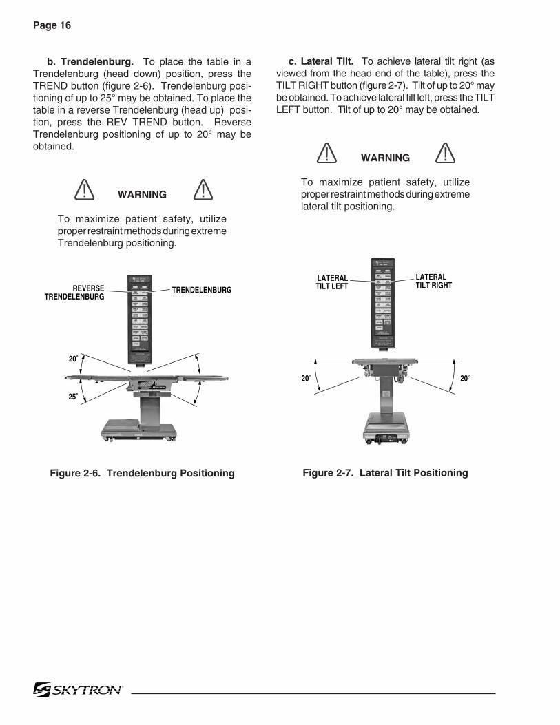
b. Trendelenburg. To place the table in aTrendelenburg (head down) position, press theTREND button (figure 2-6). Trendelenburg posi-tioning of up to 25° may be obtained. To place thetable in a reverse Trendelenburg (head up) posi-tion, press the REV TREND button. ReverseTrendelenburg positioning of up to 20° may beobtained.
WARNING
To maximize patient safety, utilizeproper restraint methods during extremeTrendelenburg positioning.
Figure 2-6. Trendelenburg Positioning
c. Lateral Tilt. To achieve lateral tilt right (asviewed from the head end of the table), press theTILT RIGHT button (figure 2-7). Tilt of up to 20° maybe obtained. To achieve lateral tilt left, press the TILTLEFT button. Tilt of up to 20° may be obtained.
WARNING
To maximize patient safety, utilizeproper restraint methods during extremelateral tilt positioning.
Figure 2-7. Lateral Tilt Positioning
25˚
20˚
REVERSETRENDELENBURG
TRENDELENBURG
20˚ 20˚
LATERALTILT LEFT
LATERALTILT RIGHT

Page 17
d. Back Section. To raise the back section,press the BACK UP button (figure 2-8). The backsection will raise up to 90° above horizontal. Tolower the back section, press the BACK DOWNbutton. The back section will go down to 40° belowhorizontal.
NOTE
If the table top is slid toward the footend, the back section will not go belowhorizontal. An audible alarm will sound.
NOTE
To prevent damage to the kidney lift, asafety interlock prevents the back sec-tion from going more than 45° abovehorizontal if the kidney lift is not all theway down. An audible alarm will sound.
Figure 2-8. Back Section Positioning
e. Elevation. To raise table top, press theTABLE UP button (figure 2-9). The table will lift apatient weight of 700 pounds up to a maximumheight of 45". To lower the table top, press theTABLE DOWN button. The table top will go downto a minimum height of 26" (minus pad).
Figure 2-9. Elevation Function
90˚
40˚
BACK UP BACK DOWN
45"
TABLEUP
TABLEDOWN
26"

Page 18
f. Top Slide. To move the table top toward thehead end, press the SLIDE HEAD button. Fromcenter position, the top will slide up to 7-1/2". Seefigure 2-10.
NOTE
If the leg section is positioned morethan 45° below horizontal, the top willnot slide toward the head end. Anaudible alarm will sound.
To move the table top toward the foot end, pressthe SLIDE FOOT button. From center position, thetop will slide up to 13-1/2". Slide function will stopand SLIDE/CTR Indicator will illuminate when tableis centered.
NOTE
If the back section is positioned belowhorizontal, the top will not slide towardthe foot end. An audible alarm willsound.
g. Leg Section. To lower the leg section, pressthe LEG DOWN button (figure 2-11). The legsection will go down to 98° below horizontal. Toraise the leg section, press the LEG UP button.The leg section will go up to level.
CAUTION
The Leg section may hit the table baseor the floor if both the leg and elevationsystems are placed in their full downposition.
NOTE
If the top is slid toward the head end, theleg section will only go down 45°. Anaudible alarm will sound.
Figure 2-11. Leg Section PositioningFigure 2-10. Top Slide
98˚
2˚
LEG UP LEG DOWN
7-1/2"
SLIDE HEAD SLIDE FOOT
13-1/2"

Page 19
Figure 2-13. Kidney Lift Positioning
j. Return To Level. To return the table top to alevel position, press the LEVEL button (figure 2-14).
NOTE
Elevation and brake system functionsare not affected by the return to levelfunction.
h. Flex Positioning. To place the table top ina flex position from horizontal, press the FLEXbutton (figure 2-12). To return the table top to ahorizontal position or into a reflex position, pressthe REFLEX button.
NOTE
When FLEX button is activated and ifthe top is slid toward the foot end, theback section will not go below horizon-tal. An audible alarm will sound.
Figure 2-12. Flex/Reflex Positioning
i. Kidney Lift. To raise the built-in kidney lift,press the KIDNEY UP button (figure 2-13). Up to5-1/2" of lift can be achieved. Press the KIDNEYDOWN button to lower the kidney lift.
NOTE
Return to Level will lower the kidney lift.
NOTE
To prevent damage to the kidney lift, asafety interlock prevents the kidney liftfrom going up if the back section is 45°above horizontal. An audible alarm willsound . Figure 2-14. Return To Level
FLEX REFLEX
5-1/2"
KIDNEY UP KIDNEY DOWN
RETURNTO LEVEL

Page 20
Figure 2-16. Emergency Back-Up Controls
CAUTION
The EMERGENCY BRAKE LOCKswitch does not activate the brake sys-tem timer. The switch must be helduntil the brakes are completely locked,approximately 10 seconds.
NOTE
The emergency back-up controlswitches will function when the table isoperating on 120VAC power, batterypower, or turned off.
c. Switches are provided for Trendelenburg,lateral tilt, back section, elevation, leg section,kidney down and brake lock. These switches arespring-loaded so they return to the neutral orcenter position when released.
2-7. Emergency Back-up Controls
a. The emergency back-up control switches arelocated under the access door on the serviceaccess cover in the table base. See figure 2-15.
Figure 2-15. Emergency Controls Location
b. In the event of either a power failure or aproblem with the hand-held pendant control, thetable can be operated using the emergency back-up switches. Simply push the desired emergencyswitch in the appropriate direction to operate thetable functions. See figure 2-16.
CAUTION
The safety interlock system is not op-erational when the emergency back-up control switches are used.
FUNCTION CONTROLACCESS DOOR
REVTREND
TILTRIGHT
BACKUP
TABLEUP
LEGUP
BRAKELOCK
TREND TILTLEFT
BACKDOWN
TABLEDOWN
LEGDOWN
KIDNEYDOWN

Page 21
2-8. Emergency Brake Release.
In case of a power failure or an electrical problemwithin the table, the emergency brake releasesystem can be used to move the table. The controlknob for this function is located on the side of thetable base and is identified by an EMERGENCYBRAKE RELEASE label. Turn the knob counter-clockwise to release the brakes. See figure 2-17.
WARNING
•DO NOT unlock brakes when a patientis on the table. An uneven patientweight load may cause instability.
•If circumstances demand table brakesto be unlocked, the patient must becentered and evenly distributed on thetable top (i.e. supine or prone position)with the table lowered to its lowestheight position. The maximum patientweight should not exceed 500 pounds.Table top slide must be centered (indi-cated by a green LED light on thependant control) prior to unlockingbrakes. Patient's head must be on thehead section. Head section must beattached in its normal orientation to thetable's back section.
•Prior to unlocking brakes, check forobstructions on the floor that mightprevent the table from moving smoothlyto new location. Relock the brakes im-mediately once the final position isreached and before commencing sur-gery. Table brakes should remain lockedat all times if patient weight exceeds500 pounds.
Figure 2-17. Emergency Brake Release
NOTE
The Emergency Brake Release Valvemust be closed and tightened (clock-wise) before activating any function.
•If the Emergency Brake Release Valvehas been operated, the UNLOCK buttonon the pendant control will have to bepressed before brakes will lock again.
SERVICE ACCESSCOVER
POWERCORD
EMERGENCYBRAKE RELEASE
BRAKE (4)

Page 22
Figure 2-19. Repositioning Head Section(for use as a Foot Extension)
2-9. Head Section
a. A quick release positioning bar located underand to the front of the head section (figure 2-18) isused to raise or lower the head section. Pull therelease bar toward the head end to allow thesection to pivot up or down. Positioning from 60°above horizontal to 90° below horizontal in 15°increments is available. Release the bar to lock thehead section in position.
2-10. Leg Section Removal.
NOTE
The leg section with the x-ray top + padattached weighs 31 lbs. It is recom-mended that the x-ray top and pad beremoved before detaching the leg section.
a. To remove the leg section, position the tabletop height to elbow height, and simultaneouslydepress both release levers and pull the leg sectionout. See figure 2-20. Press the LEG-DOWNbutton on the pendant control to position the legsection attachment pins down and out of the way.
Figure 2-18. Head Section Adjustment
b. By loosening two locking knobs beneath theback section, an additional 2" of longitudinal ad-justment can be achieved. If desired, the headsection may be removed by loosening the lockingknobs and pulling it straight out of the back section.
3501B EZ Slide Table has the capability of attach-ing the head section to the leg section for use as afoot extension ONLY. Do Not reverse the patienton the table without first consulting with SKYTRON.
Two locking knobs are located on the inside of theleg section for securing the head section. Seefigure 2-19.
Figure 2-20. Leg Section Release Levers
b. To Install Leg Section, press and hold theLEG-UP button until the leg section attachmentpins completely stop before reinstalling the legsection to the table. Pull out on the leg section afterinstallation to make sure the release levers arecompletely locked.
HEAD SECTIONRELEASE BAR
HEADSECTION
FOOT/LEGSECTION
LOCKINGKNOB
LOCKINGKNOB
(RECESSED)
FOOT/LEG SECTION
LOCKINGLEVERS
Page 23
2-11. Positioning
The use of certain optional accessories availablefrom SKYTRON further extend the positioningcapabilities of the 3501B E-Z Slide Table. Refer tothe following "Positioning Guidelines" or contactyour SKYTRON representative for further details.
WARNING
Certain accessories may limit weightcapacities. Check with your SKYTRONrepresentative.
CAUTION
Consult SKYTRON prior to using ac-cessories produced by other manufac-turers.
WARNING
Consult manufacturer's instructionswhen using high frequency surgicalequipment, cardiac defibrillator and car-diac defibrillator monitors.
WARNING
When an antistatic pathway is required,the table has to be used on an antistaticfloor.
WARNING
The antistatic properties of the tableare dependent on the use of the originalpad set which was furnished with thetable or an alternate approved replace-ment.

Page 24
3-2. Cleaning Recommendations
NOTE
Always follow current AORN JournalGuidelines to ensure proper cleaningand disinfection procedure.
The following procedures should be followed whencleaning the surgical table between cases.
Place table top in level position prior to startingcleaning procedure.
WARNING
Always follow OSHA blood-borne patho-gens standards for protective clothing,including gloves, masks and eye pro-tection when cleaning the surgical table.
Remove major contaminants from the table withdisposable materials following appropriate biohaz-ard waste disposal procedures.
Remove all table pads and place them on a flatsurface for cleaning.
CAUTION
Thoroughly read and follow themanufacturer's directions for all clean-ing fluids. DO NOT use cleaners con-taining phenolics.
Apply cleaning fluid liberally to top and sides ofeach pad and wipe with a clean lint-free cloth.
Using a clean, damp, lint-free cloth, wipe the padsto remove the cleaning fluid.
Using a clean, dry, lint-free cloth, wipe the pads toremove all moisture.
3-1. Preventive Maintenance
The following preventive maintenance checks andservices are recommended to ensure the service-ability and proper operation of your SKYTRONSurgical Table, and should only be performed byqualified SKYTRON trained personnel.
a. During normal cleaning, a general visualexamination should be made checking for leaks,loose bolts or parts, and cracked, chipped, ormissing paint. Any necessary repairs should bemade.
b. Semi-annually the following checks and ser-vices should be performed:
1. Check all hydraulic fittings, mini-valves andslave cylinders for proper operation andany signs of leaks.
2. Check the hydraulic speed controls andadjust if necessary.
3. Pressure check (with a gauge) the pres-sure relief valve.
4. Check all mechanical adjustments and ad-just as necessary.
5. Check hydraulic fluid level.
6. Lubricate the slider assembly.
7. Check function of foot leg release levers,lubricate as necessary.
SECTION III MAINTENANCE

Page 25
Repeat the steps to clean the bottom of the eachpad.
CAUTION
When using spray cleaners DO NOTspray fluids directly into electrical re-ceptacles or micro switches.
Repeat cleaning procedure for all table surfacesincluding the top, sides, elevation column, baseand all accessories.
CAUTION
Before replacing pads on the table, makesure the pads and all mating surfacesare completely dry. Moisture trappedbetween the pads and mating surfacesmay cause distortion of table tops.
WARNING
SKYTRON assumes no liability for tableperformance, table damage or injury topatient or staff when accessories notsold or serviced by SKYTRON areused on SKYTRON surgical tables.
When the cleaning procedure is complete, replaceall pads and accessories as applicable.
Remove pendant control from table side rail andapply cleaning solution to the pendant control andcord.
Use a clean cloth dampened with water to removecleaning solution.
Use another clean damp cloth to remove anyremaining residue.
Install pendant control on side rail for storage whencleaning procedure is complete.
3-3. Service
Table maintenance can be performed by trainedmaintenance personnel using SKYTRON autho-rized replacement parts and service techniques.Service instructions and parts are available fromSKYTRON.
Preventive Maintenance contracts are availablethrough your local SKYTRON representative.
To obtain service instructions, replacement parts,factory service or preventive maintenance con-tracts, contact the SKYTRON representative listedbelow.
Or contact:SKYTRON5000 36th Street S.E.Grand Rapids, MI 495121-800-SKYTRON (1-800-759-8766)Fax. 1-616-957-5053

5000 36th Street S.E., Grand Rapids, MI 495121-800-SKYTRON or 1-616-957-0500 • FAX 1-616-957-5053

SURGICAL TABLE
3501B EZ SLIDE
PARTS CATALOG
1/07


Page 1
1/07
Although current at the time of publication, SKYTRON's policy of continuous development makes thismanual subject to change without notice.
INTRODUCTION
This manual contains the exploded views and replacement parts lists for the service-able components of the SKYTRON Model 3501B EZ SLIDE Surgical Table.
Each serviceable part in these exploded views is identified by a reference number.Use this number to locate necessary part information in the parts list adjacent to the ex-ploded view.
Always use the complete SKYTRON part number and description when orderingreplacement parts.
Always use the complete table serial number (S.N.) when ordering replacementparts.
Special Tools and Maintenance Items listed on page 40.
AbbreviationsAs Required ........................................... A/ROptional ................................................... optSerial Number ....................................... S.N.Not Shown............................................... NS

Page 2

Page 3
3501B EZ SLIDE EQUIPMENT LABELS
15
14
13
12 1110
87
9
6
5
3
21
1
1514
131211
1098
7
654
32
POSSIBLE EXPLOSION HAZARD
IF USED IN THE PRESENCE OF
FLAMMABLE ANESTHETICS.
DANGER
Grounding reliability can only be achieved whenthe equipment is connected to an equivalentreceptacle marked "Hospital Only" or "Hospital Grade"
DANGER - EXPLOSION HAZARD. DO NOT USE INTHE PRESENCE OF FLAMMABLE ANAESTHETICS
DANGER - RISQUE D'EXPLOSION. NE PASEMPLOYER EN PRESENCE D'ANESTHESIQUESINFLAMMABLES
Table Capacity:Lift 700 lbs.Articulate 600 lbs.
See OperatorsManual for Limitations.
THIS PRODUCT COMPLIES WITH RADIA-TION PERFORMANCE STANDARD 21 CFRAT THE TIME OF MANUFACTURE
Manufactured:
Model No.
WARNINGUSE HEAD SECTION AS FOOT EXTENSION ONLY - WHEN REVERSING PATIENT ON TABLE REFER TO OPERATOR MANUAL.
DO NOT SIT ON END OF LEG SECTION(S) AS LOADSIN EXCESS OF 140 LBS, MAY CAUSE INSTABILITYTHAT COULD CAUSE THE TABLE TO BE TIPPED OVER.
WARNING
4
4
16
16 TWIST TO LOCK OR RELEASE PLUG
D6-035-38D3-035-60 right D3-035-61 left
D6-032-47 D6-032-46
D6-017-05
D6-065-26 D6-067-33D6-011-34
D6-011-32 D6-031-43 D6-065-22
D6-034-21 D6-065-21 D6-067-27
L1-010-00

Page 4
1. Head Section Assembly ...................................... Page 8. 2. Back Section Assembly ......................................Page 10.
3. Leg Section Assembly ...................................... Page 12. 4. Side Frame Assemblies ......................................Page 14.

Page 5
5. Back & Leg Section Cylinder Assemblies ......... Page 16. 6. Kidney Lift Assembly ........................................... Page 18.
7. Slide Assembly ................................................. Page 20. 8. Lateral Tilt Assembly ........................................... Page 22.

Page 6
9. Trendelenburg Assembly .................................. Page 24. 10. Elevation Assembly ........................................... Page 28.
11. Hydraulic Components ................................... Page 30. 12. Electro Mini-Valve Assembly ............................. Page 34.
Page 7
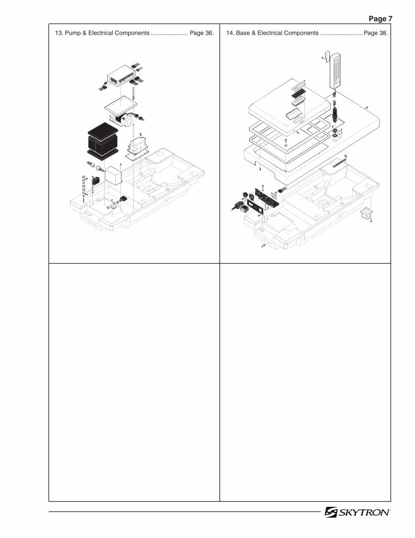
13. Pump & Electrical Components ...................... Page 36. 14. Base & Electrical Components ......................... Page 38.

Page 81. HEAD SECTION ASSEMBLY
3501B.0711.01
1
2
4
89
12
17
2223
1314
1516
17
21
18
1920
1011
3
57
252627
2829
3031
1817
24
6

Page 9
Item Part No. Description Qty.
1-010-55-P PAD SET, regular .........................................................................................................opt.1-010-55-S PAD SET, soft ..............................................................................................................opt.D3-067-00 COMPLETE HEAD SECTION .......................................................................................1
1 D3-010-19 SCREW, phillips head ...................................................................................................42 D3-067-01 TOP, head section .........................................................................................................13 D3-010-18-H VELCRO, hook ............................................................................................................A/R4 5-010-01-8 BUSHING, x-ray top ......................................................................................................25 D4-010-14 O-RING, P-12 ................................................................................................................26 D3-067-02 SHAFT, extension, head section (roll pin) .....................................................................27 D6-050-33 PIN, roll, M5 x 20 ...........................................................................................................28 D3-032-80 GEAR, trunnion, right ....................................................................................................1
D3-032-81 GEAR, trunnion, left ......................................................................................................19 D6-010-41-1 SCREW, set, M8 x 15 (plated) .......................................................................................2
10 D6-010-38-1 BOLT, allen, M6 x 15 (plated) ........................................................................................211 D6-010-40-1 WASHER, lock, M6 (plated) ..........................................................................................212 D3-067-03 FRAME, head section ...................................................................................................113 D3-034-22 BUSHING, head section ................................................................................................214 D6-010-53-1 BOLT, allen, M8 x 20 (plated) ........................................................................................215 D3-032-34 STUD, side rail mount, M8 x 45 .....................................................................................216 D3-067-04 RAIL, side, head section ...............................................................................................217 D3-032-35 STUD, side rail mount, M8 x 40 .....................................................................................418 D3-010-01 COLLAR, side rail ..........................................................................................................619 D6-010-38 BOLT, allen, M6 x 15 ......................................................................................................420 D6-010-40 WASHER, lock, M6 ........................................................................................................421 D3-067-05 PLUNGER, release, right ..............................................................................................1
D3-067-06 PLUNGER, release, left .................................................................................................122 D6-010-13 NUT, hex, M8 .................................................................................................................623 D6-010-09 WASHER, lock, M8 ........................................................................................................624 D3-032-33 RAIL, accessory ............................................................................................................125 D3-067-07 SPRING, release ...........................................................................................................226 D3-032-40 BLOCK, bearing ............................................................................................................227 D6-010-11 SCREW, set, M5 x 8 (plated) .........................................................................................228 D6-010-13-1 NUT, hex, M8 (plated) ....................................................................................................229 D3-010-24 RELEASE BAR, head section .......................................................................................130 D6-010-09 WASHER, lock, M8 ........................................................................................................231 D6-010-08 NUT, acorn, M8 .............................................................................................................2
1. HEAD SECTION ASSEMBLY
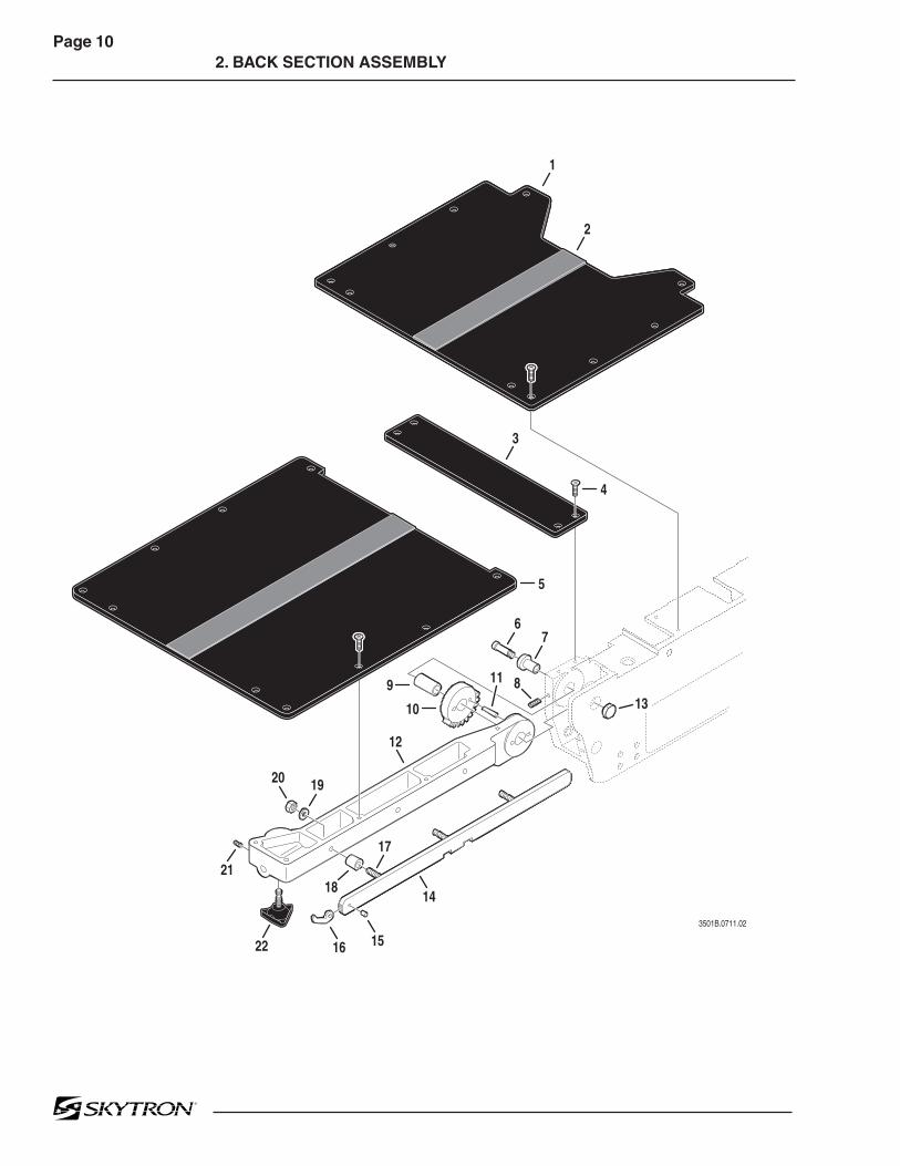
Page 102. BACK SECTION ASSEMBLY
3501B.0711.02
1
3
8
6
12
20
17
19
21
22
1418
1516
11
7
4
5
9
10
2
13

Page 11
Item Part No. Description Qty.
2. BACK SECTION ASSEMBLY
1-010-55-P PAD SET, regular .........................................................................................................opt.1-010-55-S PAD SET, soft ..............................................................................................................opt.
1 D3-035-37 TOP, seat section ...........................................................................................................12 D3-010-18-H VELCRO, hook ............................................................................................................A/R3 D3-035-01 TOP, seat section, small ................................................................................................14 D3-010-19 SCREW, phillips ..........................................................................................................A/R5 D3-035-45 TOP, back section ..........................................................................................................16 D6-032-28 BOLT, allen ....................................................................................................................27 D3-035-34 CAP, back section ..........................................................................................................18 D6-010-50 SCREW, set M6 x 15 .....................................................................................................49 D3-032-21 BUSHING, back section ................................................................................................2
10 D3-035-41 GEAR, spur, back section .............................................................................................211 D6-032-30 PIN, spur gear ...............................................................................................................412 D3-035-46 FRAME, back section, right ...........................................................................................1
D3-035-47 FRAME, back section, left .............................................................................................113 D3-032-36 CAP, back section, axis .................................................................................................214 D3-035-48 SIDE RAIL, back section, right ......................................................................................1
D3-035-49 SIDE RAIL, back section, left ........................................................................................115 D3-010-41 PIN, rail stop ..................................................................................................................216 D3-010-43 RAIL STOP, large ..........................................................................................................217 D3-032-34 STUD, side rail mount, M8 x 45 .....................................................................................618 D3-010-01 COLLAR, side rail ..........................................................................................................619 D6-010-09-1 WASHER, lock, M8 (plated) ..........................................................................................620 D6-010-13-1 NUT, M8 (plated) ...........................................................................................................621 D6-060-38 SCREW, set, M5 x 10 ....................................................................................................222 D3-010-17 KNOB, retaining .............................................................................................................2

Page 123. LEG SECTION ASSEMBLY
3501B.0711.03
1
2
10
10
9
6
8
20
4
7
3
5
11
1213
15
14
2123
2526
16
19
22
2417
18

Page 13
Item Part No. Description Qty.
3. LEG SECTION ASSEMBLY
1-010-55-P PAD SET, regular .........................................................................................................opt.1-010-55-S PAD SET, soft ..............................................................................................................opt.
1 D3-035-50 TOP, foot / leg section ....................................................................................................12 D3-010-18-H VELCRO, hook ............................................................................................................A/R3 D3-010-19 SCREW, phillips ...........................................................................................................104 D6-031-01 KNOB, locking ...............................................................................................................25 D3-035-51 FRAME, foot / leg section, right .....................................................................................1
D3-035-52 FRAME, foot / leg section, left .......................................................................................16 D3-010-43 STOP, rail, large .............................................................................................................27 D3-010-41 PIN, rail stop ..................................................................................................................28 D3-035-53 RAIL, side, foot / leg section, right .................................................................................1
D3-035-54 RAIL, side, foot / leg section, left ...................................................................................19 D3-032-35 STUD, side rail mount, M8 x 40 .....................................................................................2
10 D3-032-34 STUD, side rail mount, M8 x 45 .....................................................................................411 D3-010-01 COLLAR, side rail ..........................................................................................................612 D6-010-09-1 WASHER, lock, M8 (plated) ..........................................................................................613 D6-010-13-1 NUT, M8 (plated) ...........................................................................................................614 D3-032-51 SPRING, back section, right ..........................................................................................1
D3-032-51-1 SPRING, back section, left ............................................................................................115 D6-010-65-1 BOLT, allen, M5 x 35 (plated) ........................................................................................216 D6-032-37 PIN, roll, M4 x 30 ...........................................................................................................217 D6-010-87 SCREW, set, M6 x 20 ....................................................................................................218 D3-034-31 LEVER, axis, foot / leg section, right .............................................................................1
D3-034-32 LEVER, axis, foot / leg section, left ...............................................................................119 D3-030-05 AXIS, foot / leg section ..................................................................................................220 D3-035-55 LEVER, release, right ....................................................................................................1
D3-035-56 LEVER, release, left ......................................................................................................121 D6-067-01 SCREW, phillips, button head, M3 x 8 ...........................................................................222 D6-010-79 SCREW, phillips, button head, M3 x 5 ...........................................................................223 D3-035-57 HINGE ...........................................................................................................................224 D3-034-46 STOP, rubber .................................................................................................................225 D6-010-76 NUT, hex, M5 .................................................................................................................226 D6-010-83 BOLT, allen, M5 x 30 ......................................................................................................2

Page 144. SIDE FRAME ASSEMBLIES
3501B.0711.04
1 24
5
11 15
22
24
23
17
6
7
8
13
3
16
18
19
26
27
30
25
28
2931
32
21
20
10
12
9
14

Page 15
Item Part No. Description Qty.
4. SIDE FRAME ASSEMBLIES
1 D6-060-07 BOLT, allen, M4 x 8 ........................................................................................................22 D6-035-19 WASHER, flat, M4 .........................................................................................................23 D5-036-07 MICRO-SWITCH ...........................................................................................................14 D5-036-08 BRACKET, micro-switch mounting ................................................................................15 D3-035-08 FRAME, side, left ...........................................................................................................16 D6-066-18 SCREW, countersunk phillips, M4 x 15 .........................................................................47 D5-032-17 MICRO-SWITCH ...........................................................................................................28 D3-035-20 BRACKET, micro-switch mounting, left ..........................................................................1
D3-035-21 BRACKET, micro-switch mounting, right .......................................................................19 D3-035-58 COVER, micro-switch ....................................................................................................1
10 D6-035-04 SCREW, phillips, M4 x 6 ................................................................................................211 D3-035-20 BRACKET, slide bar, left ................................................................................................112 D6-010-53 BOLT, allen, M8 x 20 ......................................................................................................813 D3-035-22 ACTUATOR, slide, micro-switch ....................................................................................114 D6-010-28-1 BOLT, allen, M5 x 6 ........................................................................................................315 D3-035-19 BAR, slide ......................................................................................................................216 D6-010-33 BOLT, allen, M8 x 25 ......................................................................................................817 D3-035-13 COVER, hose, left .........................................................................................................1
D3-035-14 COVER, hose, right .......................................................................................................118 D6-043-10 SCREW, phillips, M4 x 8 ................................................................................................619 D3-035-59 BRACKET, slide bar, right ..............................................................................................120 D6-010-13-1 NUT, M8 (plated) ...........................................................................................................621 D6-010-09-1 WASHER, lock, M8 (plated) ..........................................................................................622 D3-035-07 FRAME, side, right ........................................................................................................123 D3-035-60 NAMEPLATE, decal, 3501B, right .................................................................................1
D3-035-61 NAMEPLATE, decal, 3501B, left ...................................................................................124 D3-010-43 STOP, rail (large) ...........................................................................................................225 D3-010-41 PIN, rail stop ..................................................................................................................226 D3-032-34 STUD, side rail mount, M8 x 45 .....................................................................................627 D3-035-04 SIDE RAIL, seat section, right .......................................................................................1
D3-035-05 SIDE RAIL, seat section, left .........................................................................................128 D3-010-01 COLLAR, side rail ..........................................................................................................629 D3-035-30 AXIS, eccentric cam ......................................................................................................230 D6-035-05 SCREW, set, M6 x 8 ......................................................................................................231 D3-035-29 ROLLER, support ..........................................................................................................232 D3-035-28 SPACER, nylon ..............................................................................................................2

Page 165. BACK & LEG SECTION CYLINDER ASSEMBLIES
3501B.0711.05
1
2
768
8
8
910
2930
1232
2526
27
31
38
31
39
32
24
20
23 38
44
11
3430
3
28
36
35
37
29
14
33
4
5
4342
30
40
412930
13
20
2019
1822
17
1615
2134
30
Page 17
Item Part No. Description Qty.
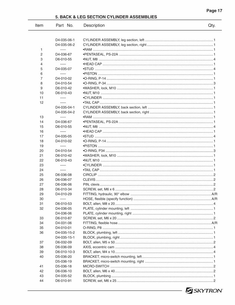
5. BACK & LEG SECTION CYLINDER ASSEMBLIES
D4-035-06-1 CYLINDER ASSEMBLY, leg section, left .......................................................................1D4-035-06-2 CYLINDER ASSEMBLY, leg section, right .....................................................................1
1 ----- •RAM .............................................................................................................................12 D4-036-67 •PENTASEAL, PS-22A ..................................................................................................13 D6-010-55 •NUT, M8 .......................................................................................................................44 ----- •HEAD CAP ...................................................................................................................15 D4-035-07 •STUD ...........................................................................................................................46 ----- •PISTON ........................................................................................................................17 D4-010-02 •O-RING, P-14 ...............................................................................................................18 D4-010-54 •O-RING, P-34 ...............................................................................................................39 D6-010-42 •WASHER, lock, M10 ....................................................................................................1
10 D6-010-43 •NUT, M10 .....................................................................................................................111 ----- •CYLINDER ...................................................................................................................112 ----- •TAIL CAP ......................................................................................................................1
D4-035-04-1 CYLINDER ASSEMBLY, back section, left ....................................................................1D4-035-04-2 CYLINDER ASSEMBLY, back section, right ..................................................................1
13 ----- •RAM .............................................................................................................................114 D4-036-67 •PENTASEAL, PS-22A ..................................................................................................115 D6-010-55 •NUT, M8 .......................................................................................................................416 ----- •HEAD CAP ...................................................................................................................117 D4-035-05 •STUD ...........................................................................................................................418 D4-010-02 •O-RING, P-14 ...............................................................................................................119 ----- •PISTON ........................................................................................................................120 D4-010-54 •O-RING, P34 ................................................................................................................321 D6-010-42 •WASHER, lock, M10 ....................................................................................................122 D6-010-43 •NUT, M10 .....................................................................................................................123 ----- •CYLINDER ...................................................................................................................124 ----- •TAIL CAP ......................................................................................................................125 D6-036-08 CIRCLIP ........................................................................................................................226 D6-036-07 CLEVIS ..........................................................................................................................227 D6-036-06 PIN, clevis ......................................................................................................................228 D6-010-34 SCREW, set, M6 x 6 ......................................................................................................229 D4-010-29 FITTING, hydraulic, 90° elbow ....................................................................................A/R30 ----- HOSE, flexible (specify function) .................................................................................A/R31 D6-010-53 BOLT, allen, M8 x 20 ......................................................................................................432 D4-036-05 PLATE, cylinder mounting, left ......................................................................................1
D4-036-06 PLATE, cylinder mounting, right ....................................................................................133 D6-010-87 SCREW, set, M6 x 20 ....................................................................................................234 D4-031-06 FITTING, flexible hose .................................................................................................A/R35 D4-010-01 O-RING, P8 ...................................................................................................................136 D4-035-15-2 BLOCK, plumbing, left ...................................................................................................1
D4-035-15-1 BLOCK, plumbing, right .................................................................................................137 D6-032-09 BOLT, allen, M5 x 50 ......................................................................................................238 D6-036-09 AXIS, eccentric cam ......................................................................................................439 D6-010-10-3 BOLT, allen, M4 x 10 ......................................................................................................440 D5-036-20 BRACKET, micro-switch mounting, left ..........................................................................1
D5-036-19 BRACKET, micro-switch mounting, right .......................................................................141 D5-036-18 MICRO-SWITCH ...........................................................................................................242 D6-036-10 BOLT, allen, M6 x 40 ......................................................................................................243 D4-035-52 BLOCK, plumbing ..........................................................................................................144 D6-010-91 SCREW, set, M6 x 25 ....................................................................................................2
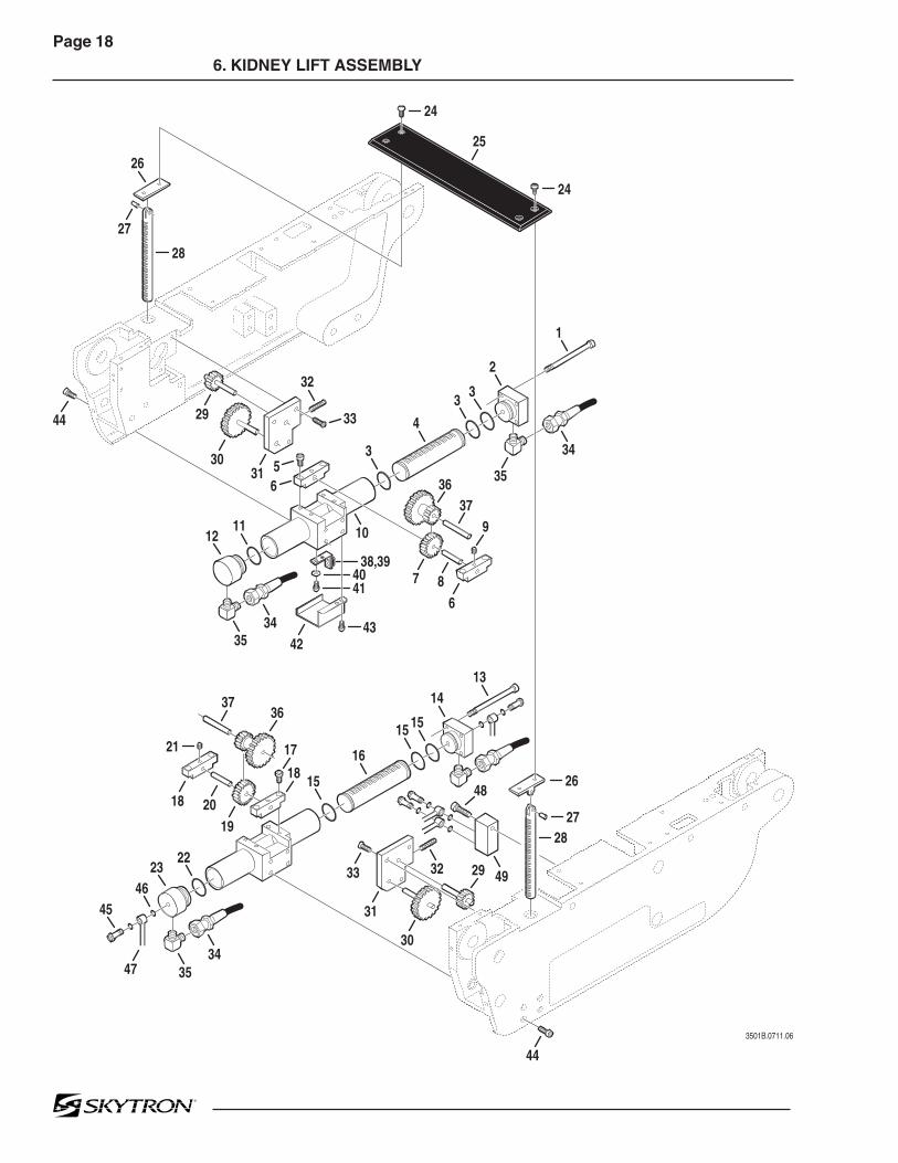
Page 186. KIDNEY LIFT ASSEMBLY
3501B.0711.06
1
2
33
4
5
33
6
3
10
32
26
28
24
24
11
1314
1515
3534
32
16
15
49
12
2223
4645
38,394041
34 4335
34
35
7
42
2944
25
27
3031
19
33
2827
26
31
30
44
2018
21
47
8
9
6
17
36
3736
29
48
37
18

Page 19
Item Part No. Description Qty.
6. KIDNEY LIFT ASSEMBLY
D4-035-09-1 CYLINDER ASSEMBLY, kidney lift, left .........................................................................11 D6-035-01 •BOLT, allen, M6 X 100 ..................................................................................................42 ----- •END CAP, left cylinder ..................................................................................................13 D4-010-57 •O-RING, P-21 ...............................................................................................................34 D4-035-09-4 •PISTON, kidney lift .......................................................................................................15 D6-010-70 •BOLT, allen, M5 x 10 ....................................................................................................46 D4-035-10 •PILLOW BLOCK ...........................................................................................................27 D4-035-11 •GEAR ...........................................................................................................................18 D4-035-11-1 •SHAFT .........................................................................................................................19 D6-010-34 •SCREW, set, M6 x 6 .....................................................................................................2
10 D4-035-09-3 •CYLINDER, kidney lift ..................................................................................................111 D4-010-12 •O-RING, P-24 ...............................................................................................................112 ----- •HEAD CAP, left cylinder ...............................................................................................1
D4-035-09-2 CYLINDER ASSEMBLY, kidney lift, right .......................................................................113 D6-035-01 •BOLT, allen, M6 x 100 ..................................................................................................414 ----- •END CAP, right cylinder ...............................................................................................115 D4-010-57 •O-RING, P-21 ...............................................................................................................316 D4-035-09-4 •PISTON, kidney lift .......................................................................................................117 D6-010-70 •BOLT, allen, M5 x 10 ....................................................................................................418 D4-035-10 •PILLOW BLOCK ...........................................................................................................219 D4-035-11 •GEAR ...........................................................................................................................120 D4-035-11-1 •SHAFT .........................................................................................................................121 D6-010-34 •SCREW, set, M6 x 6 .....................................................................................................222 D4-010-12 •O-RING, P-24 ...............................................................................................................123 ----- •HEAD CAP, right cylinder .............................................................................................124 D5-035-42-1 SCREW, round head phillips, M5 x 10 ..........................................................................425 D5-035-42 TOP, kidney lift ...............................................................................................................126 D3-032-39-1 PIVOT, kidney lift ...........................................................................................................227 D6-031-24 PIN, roll, M5 x 15 ...........................................................................................................228 D3-032-52 SHAFT, kidney lift ..........................................................................................................229 D4-035-14 GEAR ............................................................................................................................230 D4-035-13 GEAR ............................................................................................................................231 D3-035-62 COVER, gear .................................................................................................................232 D6-035-02 SCREW, set, M5 x 25 ....................................................................................................233 D6-035-03 SCREW, countersunk, phillips, M5 x 15 ........................................................................634 ----- HOSE, flexible (specify function) .................................................................................A/R35 D4-010-29 FITTING, hydraulic, 90° elbow ....................................................................................A/R36 D4-035-12 GEAR ............................................................................................................................237 D4-035-12-1 SHAFT ...........................................................................................................................238 D5-036-22 MICRO-SWITCH ...........................................................................................................139 D5-036-23 BRACKET, micro-switch mounting ................................................................................140 D6-035-19 WASHER, flat, M4 .........................................................................................................241 D6-060-07 BOLT, allen, M4 x 8 ........................................................................................................242 D5-036-21 COVER, micro-switch ....................................................................................................143 D6-060-07 BOLT, allen, M4 x 8 ........................................................................................................244 D6-010-67 BOLT, allen, M5 x 15 ......................................................................................................845 D4-010-24 BOLT, plumbing, M6 ....................................................................................................A/R46 D4-010-08 O-RING, P-7 ................................................................................................................A/R47 ----- OIL LINE (specify function) .........................................................................................A/R48 D6-010-91 BOLT, allen, M6 x 25 ......................................................................................................149 D4-036-20 VALVE, bypass ..............................................................................................................1

Page 20
7. SLIDE ASSEMBLY
3501B.0711.07
1
6
34
9
16
58
12
13
14
15
2223
25
262729
30
2
17
1819
31
3233
34
10
11
20
353637
38
21
7
2124
28

Page 21
Item Part No. Description Qty.
7. SLIDE ASSEMBLY
1 D6-035-08 SCREW, flat head, M4 x 8 .............................................................................................42 D2-035-01 COVER, hose ................................................................................................................13 D6-035-08 SCREW, flat head, M4 x 8 ............................................................................................. 84 D2-035-02 COVER, lateral tilt frame, left .........................................................................................1
D2-035-03 COVER, lateral tilt frame, right ......................................................................................15 D2-035-04 FRAME, lateral tilt ..........................................................................................................16 D6-010-04 SCREW, set, M8 x 30 ....................................................................................................67 D5-032-15 MICRO-SWITCH ...........................................................................................................28 D2-035-05 BRACKET, micro-switch ................................................................................................19 D6-060-07 BOLT, allen, M4 x 8 ........................................................................................................2
10 D6-035-04 SCREW, button head, M4 x 8 ........................................................................................211 D2-035-06 COVER, micro-switch ....................................................................................................112 D2-035-07 AXIS, slide roller, eccentric cam ....................................................................................613 D2-035-08 ROLLER, slide ..............................................................................................................1214 D2-035-10 RETAINER, slide roller ..................................................................................................415 D6-010-33 BOLT, allen, M8 x 25 .....................................................................................................1616 D2-035-09 AXIS, slide roller ............................................................................................................617 D6-010-17-1 BOLT, allen, M8 x 15 (plated) ........................................................................................218 D4-010-29 FITTING, hydraulic, 90° elbow ....................................................................................A/R19 ----- HOSE, hydraulic ..........................................................................................................A/R20 D2-035-49 COVER, slide cylinder, head end ..................................................................................1
D2-035-50 COVER, slide cylinder, foot end ....................................................................................121 D6-043-10 SCREW, phillips, M4 x 8 ................................................................................................822 D2-035-51 COVER, slide cylinder, center .......................................................................................1
D4-035-51 CYLINDER ASSEMBLY, slide ........................................................................................123 D6-035-03 •SCREW, flat head, M5 x 15 ..........................................................................................424 D4-035-20 •COVER, gear case .......................................................................................................125 D6-010-75 •SCREW, set, M5 x 5 .....................................................................................................126 D6-035-02 •SCREW, set, M5 x 25 ...................................................................................................127 D4-035-17 •COLLAR, gear ..............................................................................................................428 D4-035-19 •GEAR ...........................................................................................................................1
D4-035-19-1 •GEAR, bearing .............................................................................................................129 D4-035-18 •GEAR ...........................................................................................................................130 ----- •HOUSING & TUBE, 3501B slide cylinder ....................................................................131 ----- •RAM .............................................................................................................................132 D4-010-02 •O-RING, P-14 ...............................................................................................................233 ----- •PISTON ........................................................................................................................234 D4-035-21 •SCRAPER, SWA-30 .....................................................................................................235 D4-035-22 •SEAL, piston, SKY-22...................................................................................................236 D6-010-09 •WASHER, lock, M8 ......................................................................................................237 D6-010-53 •BOLT, allen, M8 x 20 ....................................................................................................238 D4-010-12 •O-RING, P-24 ...............................................................................................................2

Page 228. LATERAL TILT ASSEMBLY
3501B.0711.08
1
2
11,1210
13
15
29
3
5
14
1719
2221
21
20
3031
22
16
5
6
7 8 9
4
18
2324
25
262524
23
26
26
27
32
28
2726
28

Page 23
Item Part No. Description Qty.
8. LATERAL TILT ASSEMBLY
1 D6-010-53 BOLT, allen, M8 x 20 ......................................................................................................22 D6-067-23 SCREW, countersunk, phillips, M4 x 8 ..........................................................................23 D5-035-20 ACTUATOR PLATE, micro-switch ..................................................................................14 D2-036-01 MOUNT, Trendelenburg pivot housing ...........................................................................15 D6-036-16 WASHER, thrust ............................................................................................................26 D6-036-17 BEARING, thrust ...........................................................................................................17 D6-036-18 COVER, bearing ............................................................................................................18 D6-010-09 WASHER, lock, M8 ........................................................................................................19 D6-010-53 BOLT, allen, M8 x 20 ......................................................................................................1
10 D6-060-07 BOLT, allen, M4 x 8 ........................................................................................................411 D5-032-16 MICRO-SWITCH ...........................................................................................................212 D2-035-15 BLOCK, micro-switch mounting, left ..............................................................................1
D2-035-16 BLOCK, micro-switch mounting, right ............................................................................113 D2-035-14 BRACKET, micro-switch mounting ................................................................................214 D2-036-02 HOUSING, Trendelenburg pivot .....................................................................................115 D2-036-03 AXIS, lateral-tilt pivot .....................................................................................................116 D5-036-27 ACTUATOR PLATE, micro-switch ..................................................................................117 D6-067-23 SCREW, countersunk, phillips, M4 x 8 ..........................................................................418 D5-036-28 ACTUATOR PLATE, micro-switch ..................................................................................119 D2-035-52 LEVER, lateral-tilt ..........................................................................................................120 D6-010-54 BOLT, allen, M8 x 30 ......................................................................................................421 ----- HOSE, flexible (specify function) .................................................................................A/R22 D4-010-29 FITTING, hydraulic, 90° elbow ......................................................................................223 D6-010-33 BOLT, allen, M8 x 25 ......................................................................................................824 D4-035-53 CAP, end ........................................................................................................................225 D4-035-23 O-RING, S-50 ................................................................................................................226 D4-010-04 O-RING, P-44 ................................................................................................................427 D4-035-25 PISTON .........................................................................................................................228 D4-036-39 ROD, connecting ...........................................................................................................229 D6-031-18 BOLT, allen, M8 x 90 ......................................................................................................430 D2-035-33 BEARING, sealed roller .................................................................................................131 D6-036-20 CIRCLIP ........................................................................................................................132 D4-035-54 HOUSING, lateral tilt cylinder ........................................................................................1

Page 249. TRENDELENBURG ASSEMBLY
42
3501B.0711.09
1
23
10
15
16
11
12
13
18
32
5052
4551
4443
41
28
27
29
31
30
2526
16
14
17
17
53
20
33
19
22
3534
3638
3739
2123
24
40
46474849
4
5
6
7
89

Page 25
Item Part No. Description Qty.
9. TRENDELENBURG ASSEMBLY
D4-036-43 CYLINDER ASSEMBLY, Trendelenburg ........................................................................11 D4-036-44 •ROD .............................................................................................................................12 ----- •RETAINER NUT, ball joint ............................................................................................13 D6-010-51 •BOLT, allen, M6 x 10 ....................................................................................................44 D4-060-23 •O-RING, P-20 ...............................................................................................................15 D4-036-46 •CAP, end, top................................................................................................................16 D4-035-29 •O-RING, P-65 ...............................................................................................................17 D4-010-56 •O-RING, P-10A ............................................................................................................18 D4-036-47 •PISTON ........................................................................................................................19 D4-010-06 •O-RING, P-60 ...............................................................................................................1
10 D6-010-43 •NUT, M10 .....................................................................................................................111 D4-036-48 •CYLINDER ...................................................................................................................112 D4-010-10 •O-RING, G-65 ..............................................................................................................113 D4-036-49 •CAP, end, bottom..........................................................................................................114 D4-036-50 •NUT, bottom end cap....................................................................................................115 D4-010-29 FITTING, hydraulic, 90° elbow ......................................................................................116 ----- HOSE, flexible (specify function) .................................................................................A/R17 D4-036-51 SHIM..............................................................................................................................218 D4-031-06 FITTING, flexible hose ...................................................................................................119 D6-010-51 BOLT, allen, M6 x 10 ......................................................................................................220 D2-036-16 GUIDE, hose .................................................................................................................221 D2-036-11 AXIS, Trendelenburg cylinder ........................................................................................122 D6-060-38 SCREW, set, M5 x 10 ....................................................................................................223 D6-010-53 BOLT, allen, M8 x 20 ......................................................................................................424 D2-036-12 MOUNT, Trendelenburg cylinder ....................................................................................1
D2-035-59 SLIDER ASSEMBLY ......................................................................................................125 ----- SLIDER, section #1 (not available separately) ..............................................................126 D3-035-63 SLIDE RAIL ...................................................................................................................227 D6-010-38 BOLT, allen, M6 x 15 .....................................................................................................1428 D3-065-27 SLIDE, bearing ..............................................................................................................429 ----- SLIDER, section #2 (not available separately) ..............................................................130 D6-010-27 SCREW, set, M10 x 15 ..................................................................................................831 D6-010-38 BOLT, allen, M6 x 15 .....................................................................................................1632 D2-035-53 PLATE, Trendelenburg tilt, right .....................................................................................1
D2-035-54 PLATE, Trendelenburg tilt, left .......................................................................................133 D6-035-11 BOLT, allen, M8 x 35 ......................................................................................................634 D2-035-42 BRACKET......................................................................................................................135 D6-035-13 BOLT, allen ....................................................................................................................236 D2-035-39 BRACKET, shroud .........................................................................................................137 D6-010-51 BOLT, allen, M6 x 10 ......................................................................................................238 D6-010-53 BOLT, allen, M8 x 20 ......................................................................................................339 D2-036-08 BRACKET......................................................................................................................140 D6-060-07 BOLT, allen, M4 x 8 ........................................................................................................241 D2-035-55 CAP, slider section #1 ....................................................................................................142 D6-010-54 BOLT, allen, M8 x 30 ......................................................................................................243 D5-036-31 TERMINAL STRIP .........................................................................................................244 D6-011-20 SCREW, phillips, M3 x 10 ..............................................................................................845 D2-035-32 COVER, terminal strip ...................................................................................................146 D5-032-16 MICRO-SWITCH ...........................................................................................................247 D2-035-29 BRACKET, micro-switch mounting, right .......................................................................1
D2-035-28 BRACKET, micro-switch mounting, left ..........................................................................148 D6-035-19 WASHER, flat, M4 .........................................................................................................4

Page 26
9. TRENDELENBURG ASSEMBLY (continued)
42
3501B.0711.09
1
23
10
15
16
11
12
13
18
32
5052
4551
4443
41
28
27
29
31
30
2526
16
14
17
17
53
20
33
19
22
3534
3638
3739
2123
24
40
46474849
4
5
6
7
89

Page 27
Item Part No. Description Qty.
9. TRENDELENBURG ASSEMBLY (continued)
49 D6-065-08 BOLT, allen, M4 x 12 ......................................................................................................450 D2-035-30 COVER, micro-switch, right ...........................................................................................1
D2-035-31 COVER, micro-switch, left .............................................................................................151 D6-035-19 WASHER, flat, M4 .........................................................................................................452 D6-065-08 BOLT, allen, M4 x 12 ......................................................................................................453 D2-035-22 AXIS, Trendelenburg pivot .............................................................................................2

Page 2810. ELEVATION ASSEMBLY
3501B.0711.10
1
2223
25
2
3
424 5
6
8
10
11
1213
15
16
31
17
21
18
726
27
28
29
30
14
19
20
9

Page 29
Item Part No. Description Qty.
10. ELEVATION ASSEMBLY
D4-036-52 CYLINDER ASSEMBLY.................................................................................................11 D4-036-53 •CUSHION, rubber ........................................................................................................12 ----- •CAP ..............................................................................................................................13 ----- •ROD, primary piston .....................................................................................................14 D4-010-56 •O-RING, P-10A ............................................................................................................15 ----- •PISTON, primary ..........................................................................................................16 D4-036-57 •RING, back-up..............................................................................................................17 D4-050-01 •O-RING, P-29 ...............................................................................................................18 D6-010-42 •WASHER, lock, M10 ....................................................................................................19 D6-010-43 •NUT, hex, M10 ..............................................................................................................1
10 ----- •TUBE, secondary piston ..............................................................................................111 D4-034-68 •O-RING, P-31 ...............................................................................................................112 ----- • PISTON, secondary ....................................................................................................113 D4-036-63 •RING, back-up..............................................................................................................114 D4-010-54 •O-RING, P-36 ...............................................................................................................115 ----- •CAP, elevation tube ......................................................................................................116 ----- •TUBE, elevation cylinder ..............................................................................................117 D4-040-40 •O-RING, P-39 ...............................................................................................................118 ----- •BASE, elevation cylinder ..............................................................................................119 D6-010-38 BOLT, allen, M6 x 15 ......................................................................................................220 D4-010-31 FITTING, flexible hose ...................................................................................................121 ----- HOSE, flexible (specify function) .................................................................................A/R22 D6-010-38 BOLT, allen, M6 x 15 .....................................................................................................1623 D3-065-27 SLIDE, bearing ..............................................................................................................4
----- FITTING, grease ............................................................................................................424 D3-035-63 SLIDE RAIL ...................................................................................................................225 D6-010-38 BOLT, allen, M6 x 15 .....................................................................................................1426 ----- SLIDER SECTION #4 ....................................................................................................127 D6-035-16 BOLT, allen, M12 x 40 ....................................................................................................628 D2-035-56 SHROUD, elevation, upper ............................................................................................129 D2-035-57 SHROUD, elevation, middle ..........................................................................................130 D2-035-58 SHROUD, elevation, lower .............................................................................................131 D6-050-31 SCREW, phillips, M5 x 15 ..............................................................................................4

Page 3011. HYDRAULIC COMPONENTS
78
80
83
82
81
79
3501B.0711.11
1
23
22
26
31
32
2728
28
52
29
24
25
5455
34
38
23
3011
4
5
17
58
64
59
6768
69
70
73
6
7
20
7
8
9
1315
16
18
6263
19
1514
13
14
35
4546
47
51
50
4849
36
21
1011
12
33
39
41
4243
37
44
34
53
57
6365
60
61
31
40
30
1256
6621
7172
74 75
76
77

Page 31
Item Part No. Description Qty.
11. HYDRAULIC COMPONENTS
-- D4-031-23 PRESSURE RELIEF VALVE .........................................................................................11 ------ •CAP, pressure relief valve (not available separately) ...................................................12 D4-031-67 •O-RING, P-10 ...............................................................................................................13 D6-034-14 •SCREW ........................................................................................................................34 ------ •BODY, pressure relief valve (not available separately) .................................................15 D4-010-51 •O-RING, P-16 ...............................................................................................................16 D4-031-12 •SPRING........................................................................................................................17 D4-031-23-4 •VALVE, relief, 5mm dia. (steel) .....................................................................................18 ------ •HOUSING, relief valve (5mm dia. valve) (not available separately) .............................19 D4-010-24 BOLT, plumbing, M6 ....................................................................................................A/R
10 D4-010-08 O-RING, P-7 ................................................................................................................A/R11 D4-032-49 OIL LINE ......................................................................................................................A/R12 D4-032-64 HOSE, flexible, pump return ..........................................................................................113 D6-010-76 NUT, M5 .........................................................................................................................414 D6-010-77 WASHER, lock, M5 ........................................................................................................415 D6-032-14 STUD, M5 x 345 ............................................................................................................216 D4-010-52 O-RING, P-4 ................................................................................................................A/R17 D6-010-65 BOLT, allen, M5 x 35 ......................................................................................................418 D4-067-33 ELECTRO / MINI VALVE ASSEMBLY, (3-way), 24vdc, elevation ................................A/R
D4-067-35 ELECTRO / MINI VALVE ASSEMBLY, (4-way), 24vdc.................................................A/R19 D4-010-40 CAP, end ........................................................................................................................120 D6-010-64 BOLT, allen, M5 x 40 ......................................................................................................221 ------ OIL LINE (specify function) .........................................................................................A/R22 D4-010-26 BOLT, plumbing, M6 (long) ..........................................................................................A/R23 D4-036-66 TERMINAL, plumbing ....................................................................................................124 D4-010-31 FITTING, flexible hose .................................................................................................A/R25 ------ HOSE, flexible (specify function) .................................................................................A/R26 D6-032-13 BOLT, allen, M6 x 140....................................................................................................227 D6-010-85 WASHER, flat, M6 .........................................................................................................228 D6-031-16 BUSHING, isolation .......................................................................................................429 D4-032-81 STAND-OFF ..................................................................................................................230 ------ OIL LINE (specify function) .........................................................................................A/R31 ------ FLEXIBLE HOSE (specify function) ............................................................................A/R32 ------ OIL LINE (specify function) .........................................................................................A/R33 D4-032-51 FLEXIBLE TUBE ...........................................................................................................134 ------ OIL LINE, (specify function) ........................................................................................A/R-- D4-017-15 EMERGENCY BRAKE RELEASE ASSEMBLY .............................................................135 D4-041-15 •O-RING, P18 ................................................................................................................136 D4-017-19 •PLUNGER ....................................................................................................................137 D4-010-08 •O-RING, P-7 .................................................................................................................138 D4-017-16 •BLOCK, emergency brake release ...............................................................................139 D6-017-34 •PLUG, cap ....................................................................................................................240 D4-010-08 •O-RING, P-7 .................................................................................................................241 D6-017-32 •SPACER .......................................................................................................................142 D4-017-18 •PILOT PLUNGER .........................................................................................................143 D4-017-17 •VALVE ..........................................................................................................................144 D6-017-33 •SPRING........................................................................................................................145 D6-035-06 •SCREW, set, M6 x 25 ...................................................................................................246 D6-010-41 •NUT, hex, M6 ................................................................................................................247 D6-017-31 •RING, retaining ............................................................................................................148 D6-010-87 •SCREW, set, M6 x 20 ...................................................................................................149 D6-017-30 •KNOB ...........................................................................................................................1

Page 32
11. HYDRAULIC COMPONENTS (continued)
78
80
83
82
81
79
3501B.0711.11
1
23
22
26
31
32
2728
28
52
29
24
25
5455
34
38
23
3011
4
5
17
58
64
59
6768
69
70
73
6
7
20
7
8
9
1315
16
18
6263
19
1514
13
14
35
4546
47
51
50
4849
36
21
1011
12
33
39
41
4243
37
44
34
53
57
6365
60
61
31
40
30
1256
6621
7172
74 75
76
77

Page 33
Item Part No. Description Qty.
11. HYDRAULIC COMPONENTS (continued)
50 D6-060-38 •SCREW, set, M5 x 10 ...................................................................................................151 D6-017-29 •DECAL .........................................................................................................................152 D6-010-99 BOLT, allen, M5 x 60 ......................................................................................................253 D4-067-34 ELECTRO / MINI VALVE ASSEMBLY (3-way), 24vdc, brake (blue dot) .....................A/R54 D6-010-73 BOLT, allen, M6 x 12 ......................................................................................................455 D1-036-04 PLATE, electro / mini valve assembly mounting ............................................................156 D6-032-63 FITTING, flexible hose ...................................................................................................157 D5-034-33 FITTING.........................................................................................................................158 D6-010-76 NUT, hex, M5 .................................................................................................................459 D6-010-77 WASHER, lock, M5 ........................................................................................................460 D4-034-32 PUMP / MOTOR ASSEMBLY ........................................................................................161 D5-034-33-1 FITTING.........................................................................................................................162 D4-032-67 FITTING, flexible hose ...................................................................................................163 D4-032-66 TUBE, suction ...............................................................................................................164 D4-031-65 ISOLATION MOUNT, motor ...........................................................................................465 D4-030-12 FITTING, hydraulic, 90° .................................................................................................166 D6-010-67 BOLT, allen, M5 x 15 ......................................................................................................467 D4-031-14 COVER, oil tank ............................................................................................................168 D4-031-13 GASKET, oil tank cover .................................................................................................169 D4-031-11 STRAINER, oil ...............................................................................................................170 D4-030-19 TUBE, induction ............................................................................................................171 D6-010-51 BOLT, allen, M6 x 10 ......................................................................................................272 D6-010-85 WASHER, flat, M6 .........................................................................................................273 D4-036-64 RESERVOIR, oil tank ....................................................................................................174 D4-036-65 PLATE, oil tank receiving ...............................................................................................175 D4-010-39 CAP, oil filler ..................................................................................................................176 D4-010-38 FITTING, oil filler ...........................................................................................................177 D4-010-37 GASKET, oil filler ...........................................................................................................178 D6-010-30 BOLT, allen, M6 x 20 ......................................................................................................479 D6-010-36 WASHER .......................................................................................................................480 D6-010-39 BOLT, allen, M6 x 45 .....................................................................................................1681 D4-031-96 PAD, brake, self-leveling, hard .......................................................................................2
D4-031-97 PAD, brake, self-leveling, soft ........................................................................................282 D4-031-95-1 SEAT, brake, rubber .......................................................................................................483 D4-035-47 CYLINDER ASSEMBLY, brake ......................................................................................4

Page 3412. ELECTRO / MINI-VALVE ASSEMBLY
3501B.0711.12
2
34
5
6
11
1213
14
14
17
15
16
789
10
2928
26
27
2524
23
2221 19
27
26
25
24
232221
18
19
20
2928
18
1

Page 35
Item Part No. Description Qty.
12. ELECTRO / MINI-VALVE ASSEMBLY
1 D6-010-65 BOLT, allen, M5x35........................................................................................................22 D4-010-41 PLUG, cap ...................................................................................................................A/R3 D4-010-08 O-RING, P-7 ................................................................................................................A/R4 D4-010-42 SPRING, return ...........................................................................................................A/R5 D4-010-25 VALVE, non-return .......................................................................................................A/R6 ----- VALVE BLOCK, 4-way (not available separately) ........................................................A/R
----- VALVE BLOCK, 3-way (not available separately) ........................................................A/R7 ----- BALL, check (not available separately) .......................................................................A/R8 D4-050-12 O-RING, P-5 ................................................................................................................A/R9 ----- SPRING (not available separately) ..............................................................................A/R
10 ----- PLUG (not available separately) ..................................................................................A/R11 D4-010-20 O-RING, P-3 ................................................................................................................A/R12 ----- VALVE, needle, speed control (not available separately) ............................................A/R13 D4-010-19 O-RING, P-6 ................................................................................................................A/R14 D4-010-01 O-RING, P-8 ................................................................................................................A/R15 ----- PILOT PLUNGER (not available separately) ...............................................................A/R16 ----- VALVE BLOCK (not available separately) ...................................................................A/R17 ----- VALVE BLOCK (not available separately) ...................................................................A/R18 D4-010-52 O-RING, P-4 ................................................................................................................A/R19 D4-010-51 O-RING, P16 ...............................................................................................................A/R20 ----- SPOOL VALVE (not available separately) ...................................................................A/R21 D4-034-28 RETAINER, spool valve ...............................................................................................A/R22 D4-034-29 SPRING, return, spool valve .......................................................................................A/R23 ----- GUIDE, bushing (not available separately) ..................................................................A/R24 D4-010-14 O-RING, P-12 ..............................................................................................................A/R25 D4-034-31 PLUNGER, spool valve ...............................................................................................A/R26 D5-067-37 SOLENOID, 24VDC .....................................................................................................A/R
D5-067-02 •PIN, connector ...........................................................................................................A/R27 D5-034-37 HOUSING, solenoid ....................................................................................................A/R28 D6-010-78 WASHER, lock, M3 ........................................................................................................829 D6-010-79 SCREW, phillips, M3x5 ..................................................................................................8

Page 36
13. PUMP & ELECTRICAL COMPONENTS
3501B.0711.13
17
2
3
65
8
9
12
16
17
19
13
14
15
20
27
272728
2829
212322
2524
18
1011
4
26
2930
31
3234
33
34

Page 37
Item Part No. Description Qty.
13. PUMP & ELECTRICAL COMPONENTS
1 D5-036-02 RELAY BOX ...................................................................................................................12 D5-067-32 CONNECTOR, 2-pin, female .........................................................................................13 D5-067-30 CONNECTOR, 26-pin, female (CN-10) .........................................................................14 D5-067-28 CONNECTOR, 16-pin, female (CN-1A) .........................................................................15 D5-067-27 CONNECTOR, 20-pin, female (CN1B) ..........................................................................16 D5-067-26 CONNECTOR, 7-pin, female (CN-7) .............................................................................17 D5-067-24 CONNECTOR, 12-pin, female (CN-3) ...........................................................................18 D6-032-21 BOLT, allen, M5 x 105....................................................................................................29 D1-032-23 TRAY, relay box .............................................................................................................1
10 D5-067-33 CONNECTOR, 4-pin, female .........................................................................................111 D5-067-34 CONNECTOR, 4-pin, male ............................................................................................112 D1-032-22 STAND-OFF ..................................................................................................................213 D1-032-21 COVER, battery .............................................................................................................114 D5-032-43 BATTERY, 12V ...............................................................................................................215 D1-032-20 TRAY, battery .................................................................................................................116 D6-032-18 BOLT, allen ....................................................................................................................417 D5-035-21 TRANSFORMER ...........................................................................................................118 D1-036-03 PLATE, transformer mounting .......................................................................................119 D6-032-17 SCREW, phillips ............................................................................................................420 D5-032-60 CONNECTOR, 6-pin, male ............................................................................................221 D5-032-59 CONNECTOR, 6-pin, female .........................................................................................122 D5-067-22 CAPACITOR / RECTIFIER UNIT ...................................................................................123 D6-010-28 BOLT, allen, M5 x 6 ........................................................................................................224 D6-060-07 BOLT, allen, M4 x 8 ........................................................................................................225 D5-034-49 BUZZER ........................................................................................................................126 D6-034-13 STAND-OFF ..................................................................................................................227 D6-010-76 NUT, hex, M5 .................................................................................................................328 ----- GROUND WIRE ..........................................................................................................A/R29 D6-017-28 WASHER, lock, M5 ........................................................................................................230 D6-035-02 SCREW, set, M5 x 25 ....................................................................................................131 D6-067-22 NUT ...............................................................................................................................132 D6-067-23 SCREW, phillips, countersunk, M4 x 8 ..........................................................................233 D5-067-35 BRACKET, circuit breaker .............................................................................................134 D5-067-36 CIRCUIT BREAKER ASSEMBLY, 15A ..........................................................................1

Page 3814. BASE & ELECTRICAL COMPONENTS
2501B.0711.14
9
16
10
11
13
17
18
19
20
2221
15
232425
30
3233
34 35
31 29
14
12
67
34
8
36
3738
39
40
5
2827
26
1
2

Page 39
Item Part No. Description Qty.
14. BASE & ELECTRICAL COMPONENTS
D5-035-18 PENDANT CONTROL ASSEMBLY ...............................................................................11 D5-031-14 •HOOK, pendant ............................................................................................................12 D5-035-22 •CORD ASSEMBLY, pendant control .............................................................................13 D6-011-20 SCREW, phillips, countersunk, M3 x 10 ........................................................................44 D5-034-06 CONNECTOR, 7-pin, female .........................................................................................15 D5-034-05 GASKET, connector .......................................................................................................16 D6-067-03 SCREW, phillips, countersunk, M3 x 6 ..........................................................................47 D6-035-39 COVER ..........................................................................................................................18 D6-050-37 SCREW, phillips, M4 x 8 ................................................................................................19 D6-036-01 SCREW, phillips, M4 x 8 ................................................................................................4
10 D5-034-38 FACEPLATE, 6-switch ...................................................................................................111 D5-034-39 COVER, switch assembly ..............................................................................................112 D5-034-40 SWITCH PLATE ASSEMBLY.........................................................................................1
D5-034-41 •SWITCH, toggle, 2-position ..........................................................................................613 D1-034-01 COVER, service access ................................................................................................114 D6-050-37 SCREW, phillips, countersunk, M4 x 8 ..........................................................................415 D6-010-51 BOLT, allen, M6 x 10 ......................................................................................................216 D6-010-85 WASHER, flat, M6 .........................................................................................................217 D1-034-03 FRAME ..........................................................................................................................118 D1-034-04 GASKET ........................................................................................................................119 D3-035-64 HOUSING, base ............................................................................................................120 D6-010-67 BOLT, allen, M5 x 15 .....................................................................................................1021 D6-010-51 BOLT, allen, M6 x 10 ......................................................................................................322 D6-010-40 WASHER, lock, M6 ........................................................................................................323 D5-067-38 CONNECTOR, 12-pin, female .......................................................................................124 D6-067-25 SCREW .........................................................................................................................225 D5-067-39 BATTERY INDICATOR ASSEMBLY...............................................................................126 D1-036-02 BRACKET......................................................................................................................127 D5-065-06 COVER ..........................................................................................................................128 D6-034-05 SCREW, phillips, M6 x 7 ................................................................................................429 D6-060-41 SCREW, allen, M4 x 3 ...................................................................................................430 D1-036-01 FACEPLATE ..................................................................................................................131 D5-034-46 SWITCH, on/off (includes cover) ...................................................................................132 D5-066-31 POWER CORD ASSEMBLY ..........................................................................................133 D6-034-05 SCREW, phillips, M6 x 7 (plated) ..................................................................................234 D5-066-32 COVER, w/chain ............................................................................................................135 D5-066-30 CONNECTOR, 3-prong .................................................................................................136 D6-034-20 EQUALIZATION TERMINAL ..........................................................................................137 D6-010-51 BOLT, allen, M6 x 10 ......................................................................................................138 D6-065-28 SPRING .........................................................................................................................139 D1-010-30 CASTER, 105HBP.........................................................................................................440 D6-010-96 BOLT, allen, M10 x 20 ...................................................................................................16

Page 40
Item Part No. Description Qty.
6-050-02 GAUGE, oil pressure ............................................................................................... A/RD6-010-89 GREASE, slider ..................................................................................................... 2.8 ozD6-010-90 OIL, hydraulic ........................................................................................................... QtD4-011-02 HOSE, hydraulic, specify length .............................................................................. A/RD4-011-03 FITTING, hydraulic hose end .................................................................................. A/R
SPECIAL TOOLS & MAINTENANCE ITEMS


5000 36th Street S.E. • Grand Rapids, MI 495121.800.SKYTRON • 1.616.957.0500 • FAX 1.616.957.5053

SURGICAL TABLEMAINTENANCE MANUAL
MODEL 3501B EZ SLIDE
1/07


Page 1
TABLE OF CONTENTSTitle Page
1/07
Although current at the time of publication, SKYTRON'S policy of continuous development makes thismanual subject to change without notice.
SECTION I HYDRAULIC SYSTEM......................................................................................................... 6
1-1. General ......................................................................................................................................... 61-2. Component Operation .................................................................................................................. 7
a. Motor/Pump Operation ............................................................................................................. 7b. Pressure Relief Valve ............................................................................................................... 7c. Mini-Valves ............................................................................................................................... 8d. Hydraulic Cylinders (Slave Cylinders) .................................................................................... 10e. Elevation Cylinder Return Circuit ........................................................................................... 12f. Brake System ......................................................................................................................... 12g. Emergency Brake Release..................................................................................................... 13h. Flex/Reflex System ................................................................................................................. 13
1-3. Hydraulic Adjustments ................................................................................................................ 14a. Fluid Level .............................................................................................................................. 14b. Bleeding The Hydraulic System ............................................................................................. 14c. Pressure Relief Valve ............................................................................................................. 14d. Speed Controls ....................................................................................................................... 15
SECTION II MECHANICAL TABLE ADJUSTMENTS........................................................................... 16
2-1. Back Section Gear Mesh Adjustment ......................................................................................... 162-2. Hydraulic Cylinder Adjustment .................................................................................................... 16
a. Back Section .......................................................................................................................... 16b. Leg Section ............................................................................................................................ 16c. Trendelenburg Cylinder Ball Joint ........................................................................................... 17
2-3. Head Section Adjustment ........................................................................................................... 172-4. Slide Roller Adjustment ............................................................................................................... 182-5. Side Rails ..................................................................................................................................... 182-6. Casters ........................................................................................................................................ 18
SECTION III HYDRAULIC TROUBLESHOOTING ............................................................................... 19
3-1. Precautions ................................................................................................................................. 193-2. Troubleshooting Notes ................................................................................................................ 193-3. ELEVATION DIAGNOSIS CHART ............................................................................................. 203-4. TRENDELENBURG DIAGNOSIS CHART ................................................................................. 213-5. LATERAL - TILT DIAGNOSIS CHART ....................................................................................... 223-6. FLEX SYSTEM DIAGNOSIS CHART.......................................................................................... 233-7. BACK SECTION DIAGNOSIS CHART........................................................................................ 243-8. LEG SECTION DIAGNOSIS CHART .......................................................................................... 253-9. SLIDE DIAGNOSIS CHART ........................................................................................................ 263-10. KIDNEY LIFT DIAGNOSIS CHART............................................................................................ 273-11. BRAKE CIRCUIT DIAGNOSIS CHART...................................................................................... 283-12. Flexible Hose Identification and Placement ................................................................................ 293-13. Kidney Lift System ....................................................................................................................... 30

Page 2
TABLE OF CONTENTS (continued)Title Page
WARNING
Indicates a possibility of personal injury.
CAUTION
Indicates a possibility of damage toequipment.
NOTE
Indicates important facts or helpful hints.
SECTION IV ELECTRICAL SYSTEM ................................................................................................... 32
4-1. General ....................................................................................................................................... 324-2. Components ............................................................................................................................... 32
SECTION V ELECTRICAL TROUBLESHOOTING ............................................................................... 34
5-1. General ....................................................................................................................................... 345-2. Troubleshooting Notes ................................................................................................................ 345-3. Main Switch ................................................................................................................................ 345-4. Batteries ...................................................................................................................................... 355-5. Capacitor / Rectifier / AC120V Transformer ................................................................................ 365-6. Pendant Control .......................................................................................................................... 375-7. Auxiliary Switches ....................................................................................................................... 395-8. Relay Box ................................................................................................................................... 405-9. Main Wire Harness Continuity Tests .......................................................................................... 425-10. Solenoids .................................................................................................................................... 435-11. Motor/Pump Assembly................................................................................................................ 445-12. Return-to-Level / Positioning Inhibit Micro-Switches ................................................................... 455-13. Micro-Switch Troubleshooting ..................................................................................................... 46

Page 3BASIC RECOMMENDED TOOLS:
1/8". 1/4" STRAIGHT BLADE SCREWDRIVERS#2 PHILLIPS SCREWDRIVERHYDRAULIC PRESSURE GAUGE SKYTRON P.N. 6-050-02METRIC ALLEN WRENCHES 1.5mm-8mmADJUSTABLE CRESCENT WRENCHDIGITAL VOLTMETER, TRUE RMSMETRIC OPEN END WRENCHES 7mm-18mmLEVEL (CARPENTERS)GREASE GUNBEARING GREASE P.N. D6-010-89-1
BASIC RECOMMENDED MAINTENANCE PROCEDURES
The basic items notes below should be inspected at a minimal interval period of 6 months (dependant onusage). For optimal usage, safety and longevity of the product, have it serviced only by an authorizedSkytron representative with authentic Skytron replacement parts.
• Check Power Cord (if applicable)• Check Pendant Control (if applicable)• Check Oil Level in Reservoir• Check For Hydraulic Leaks• Check Pressure Relief Valve Setting• Check All Table Functions• Check Side Rails and Gravity Stops• Check Velcro• Check Lateral Tilt Housing Bolts• Lubricate Elevation Slider Assembly with Mobilux EP (Extreme Pressure) Grease P/N D6-010-89-1• Tighten X-Ray Top Stand-Offs, Use Blue Loc-Tite• Lubricate Casters• Check brake pads for wear and inspect brake cylinders for proper operation.• Inspect the Trendelenburg Cylinder & Ball Joint Retainer Nut
Only facility-authorized Skytron trained, maintenance personnel should troubleshoot theSkytron 3501B EZ SLIDE Surgical Table. Trouble shooting by unauthorized personnelcould result n personal injury or equipment damage.
How to contact us:SKYTRON
5000 36th St. SE, Grand Rapids, MI 49512PH: 1-800-759-8766 (SKY-TRON)
FAX: 616-957-5053

Page 43501B EZ SLIDE EQUIPMENT LABELS
15
14
13
12 1110
87
9
6
5
3
21
1
1514
131211
1098
7
654
32
POSSIBLE EXPLOSION HAZARD
IF USED IN THE PRESENCE OF
FLAMMABLE ANESTHETICS.
DANGER
Grounding reliability can only be achieved whenthe equipment is connected to an equivalentreceptacle marked "Hospital Only" or "Hospital Grade"
DANGER - EXPLOSION HAZARD. DO NOT USE INTHE PRESENCE OF FLAMMABLE ANAESTHETICS
DANGER - RISQUE D'EXPLOSION. NE PASEMPLOYER EN PRESENCE D'ANESTHESIQUESINFLAMMABLES
Table Capacity:Lift 700 lbs.Articulate 600 lbs.
See OperatorsManual for Limitations.
THIS PRODUCT COMPLIES WITH RADIA-TION PERFORMANCE STANDARD 21 CFRAT THE TIME OF MANUFACTURE
Manufactured:
Model No.
WARNINGUSE HEAD SECTION AS FOOT EXTENSION ONLY - WHEN REVERSING PATIENT ON TABLE REFER TO OPERATOR MANUAL.
DO NOT SIT ON END OF LEG SECTION(S) AS LOADSIN EXCESS OF 140 LBS, MAY CAUSE INSTABILITYTHAT COULD CAUSE THE TABLE TO BE TIPPED OVER.
WARNING
4
4
16
16 TWIST TO LOCK OR RELEASE PLUG
D6-035-38D3-035-60 right D3-035-61 left
D6-032-47 D6-032-46
D6-017-05
D6-065-26 D6-067-33D6-011-34
D6-011-32 D6-031-43 D6-065-22
D6-034-21 D6-065-21 D6-067-27
L1-010-00
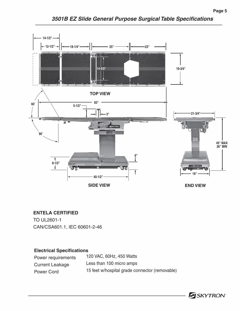
Page 5
3501B EZ Slide General Purpose Surgical Table Specifications
Electrical Specifications
Power requirements
Current Leakage
Power Cord
120 VAC, 60Hz, 450 Watts
Less than 100 micro amps
15 feet w/hospital grade connector (removable)
12-1/2" 18-1/4" 25" 23"
14-1/2"
19-3/4"
5-1/2"
3"
83"
TOP VIEW
90˚
60˚
14-1/2"
40-1/2"
SIDE VIEW
8-1/2"
6"
19"
21-3/4"
45" MAX26" MIN
END VIEW
ENTELA CERTIFIED
TO UL2601-1
CAN/CSA601.1, IEC 60601-2-46

Page 6
Figure 1-1. Hydraulic Block Diagram
1-1. General
The hydraulic system (with the exception of thehydraulic cylinders and hoses) is contained within thebase of the table. The hydraulic valves and pump areelectrically controlled by the use of a hand-held pushbutton pendant control. The power requirements forthe table are 120 VAC, 5 amp, 60 Hz.
The table contains the following components. Re-fer to the block diagram (figure 1-1) for relationship.
a. Oil Reservoir - Main oil supply. Approximatelytwo quarts.
b. Motor/Pump Assembly - A positive displace-ment gear type pump provides the necessary oilpressure and volume.
c. Pressure Relief Valve - Provides an alternate oilpath when the hydraulic cylinders reach the end oftheir stroke.
d. Electro/Hydraulic Mini-Valve Assemblies -Thesedirect the fluid to the appropriate hydraulic cylin-ders.
e. Hydraulic Lines, Fittings, Connections - Theyprovide a path for the hydraulic oil.
f. Hydraulic Cylinders - They convert the hydraulicfluid pressure and volume into mechanical motion.
SECTION I HYDRAULIC SYSTEM
82206-101
ELEV SLIDE
BRAKE
KIDNEYLEGBACKFLEXTILTTREND
1
1
3
2
25
4 27 7 9
6 8
4 8 10
1110
1 5 7 9 11 12 13
MOTOR/PUMP
ASSEMBLY
PLUMBINGTERMINAL
ELEVATIONCYLINDER
TRENDELENBURGCYLINDER
TILTCYLINDER
BACK SECTION KIDNEY LIFT
SLIDE
LEG SECTION
MINI-VALVES
(4) BRAKE ASSEMBLIES
3
2 4 5
6 7 8 9
1213
10 11
EMERGENCYBRAKE RELEASE
14
3
6
12 13

Page 71-2. Component Operation
a. Motor/Pump Operation
The motor/pump assembly is a gear type pumpthat provides the oil pressure and volume for theentire hydraulic system. The pump has an inletside and an outlet side. The inlet side is connectedto the reservoir which provides the oil supply. Thereservoir has a very fine mesh screen strainerwhich prevents foreign material from entering theoil system.
The output line of the pump is connected to themain oil galley which is internal and common to allthe hydraulic mini-valves and pressure relief valve.Also, common to the hydraulic mini-valves andpressure relief valve is an oil galley that internallyconnects to the oil reservoir to provide a return pathfor the hydraulic oil. See figure 1-2.
Figure 1-4. Pressure Relief Valve Functioning
Figure 1-3. Pressure Relief Valve NotFunctioning
Figure 1-2.
b. Pressure Relief Valve
This device provides an alternate oil path back tothe reservoir when the hydraulic cylinders reachthe end of their stroke and the pump continues torun. If this path were not provided, the pump motorwould stall because the oil cannot be compressed.The pressure relief valve is directly connected tothe mini-valve bodies and shares both the commoninternal main pressure oil galley, and the return oilgalley that internally connects to the reservoir. Seefigure 1-3.
The main component of the valve is an adjustablespring loaded plunger that when it is pushed offfrom its seat by the oil pressure the oil then flowsback into the reservoir. See figure 1-4. Turning theadjustment nut clockwise increases the amount ofoil pressure required to open the valve, and turningit counterclockwise decreases the amount of oilpressure. (See adjustment section for specifica-tion.)
82206-102
MAIN PRESSUREOIL GALLERY (internal)
MINI-VALVES
OIL RESERVOIR
PUMPOUTLETPUMP
INLET
PRESSURERELIEF VALVE
MOTOR/PUMPASSEMBLY
MAIN RETURNOIL GALLERY
(internal)82206-103
PRESSURE RELIEFADJUSTMENT NUT
PRESSUREGAUGE
SPRINGLOADED
PLUNGER
PRESSURE
RETURN
82206-104
PRESSURE RELIEFADJUSTMENT NUT
PRESSUREGAUGE
SPRINGLOADED
PLUNGER
OIL LINEFROMPUMP
OIL RESERVOIR

Page 8
Figure 1-5. Mini-Valve in Neutral Position
c. Mini-Valves
The operation of the mini-valves is identical for alltable functions except the elevation and brakecircuits. These two hydraulic circuits use a 3-way(single check valve) type mini-valve. All other func-tions use a 4-way (dual check valve) type mini-valve.
Either type mini-valve is controlled by two pushingtype, electrically operated solenoids. The sole-noids push the spool valve (located in the lowerportion of the valve) one way or the other. Thismotion opens the main supply galley (which haspump pressure) allowing the oil to flow through thevarious parts of the mini-valve to the function. Thespool valve also opens an oil return circuit whichallows the oil to return to the oil reservoir.
The main components of the mini-valve and theirfunctions are listed below:
1. Spool Valve - Opens the main oil galley(pump pressure) to either mini-valve outlet de-pending on which direction the spool valve ispushed. Also it provides a return path for the oilreturning back into the reservoir.
2. Pilot Plunger - There are two plungers in afour-way mini-valve (one in a 3-way mini-valve),one under each check valve. The purpose of thepilot plungers is to mechanically open the returncheck valve allowing the oil to return back into thereservoir.
3. Check Valve - Two are provided in each four-way mini-valve to seal the oil in the cylinders and oillines and prevent any movement of the table. Onecheck valve is provided in a 3-way mini-valve.
4. Speed Controls - There are two speedcontrols in each 4-way mini-valve. They are needlevalve type controls which restrict the volume of oilreturning back into the reservoir, thereby control-ling the speed of the table surface movement. A 3-way mini-valve has only one speed adjustment.
The speed controls are always located in the returnoil circuit to allow the movement of the cylinder to becontrolled. Also, by using this control method, itdoes not matter what size cylinder and piston isused because the speed is controlled by restricting
the return oil. If the pump puts out more volume toa slave cylinder than is allowed by the speedcontrol, the pressure relief valve opens and pro-vides an alternate path for the pump oil to return tothe reservoir.
The following material depicts the three operatingpositions of the mini-valve. The movement of theslave cylinder piston (extend or retract) is deter-mined by which port of the Mini-Valve is activated.
Mini-Valve in Neutral Position(No fluid flow) See figure 1-5.
• Spool Valve Centered - This closes off both oilpressure and oil return galleys.
• Pilot Plungers Both Closed -The pilot plung-ers control the opening of the check valves. If theyare closed, the check valves must be closed.
• Check Valves - Both check valves are closedtrapping the oil in the cylinder and oil lines.
• Speed Control - When the mini-valve is in theneutral position, the speed control does not affectanything.
OIL RETURN(RETURN)
OIL GALLERY(PRESSURE)
SPOOLVALVE
SOLENOIDPISTON
PILOTPLUNGER
CHECKVALVE
SPEEDCONTROL
BALLVALVE OIL LINEOIL LINE
82206-105

Page 9Mini-Valve Right Port Activated(See figure 1-6)
Right Mini-Valve Port is Supply LineLeft Mini-Valve Port is Return Line
Mini-Valve Left Port Activated(See figure 1-7.)
Left Mini-Valve Port is Supply LineRight Mini-Valve Port is Return Line
Figure 1-7. Mini-Valve Left Port Activated
• Spool Valve -Pushed to the right by electricsolenoid. This opens the internal oil pressuregalley allowing the fluid to go through the checkvalve and on to the cylinder. Also, the spool valveopens the oil return line providing an oil paththrough the internal oil galley back to the reservoir.
• Pilot Plunger Valve - Right pilot plunger valveis pushed up by the incoming oil pressure mechani-cally opening the check valve located above it in thereturn circuit. This action allows the oil from thereturn side of the slave cylinder to go back into thereservoir. The left pilot plunger valve is notaffected in this operation mode.
• Check Valves - Both check valves are openedin this operation mode. The left check valve ispushed open by the oil pressure created by thepump. The oil then continues through the lines andsupplies the inlet pressure to move the slavecylinder piston. The right check valve is held openmechanically by the pilot plunger and allows the oilfrom the return side of the slave cylinder to gothrough the mini-valve back to the reservoir.
• Speed Control - The left speed control(output side) does not have any effect in thisoperation mode because the oil is routed aroundthe speed control through a bypass valve to theoutput port. The right speed control controls thespeed of the table function by restricting the flow ofoil going back into the reservoir.
Figure 1-6. Mini-Valve Right Port Activated
• Spool Valve - Pushed to the left by electricsolenoid. This opens the internal oil pressuregalley allowing the fluid to go through the checkvalve and on to the cylinder. Also, the spool valveopens the oil return line providing an oil paththrough the internal oil galley back to the reservoir.
• Pilot Plunger Valve - Left pilot plunger valveis pushed up by the incoming oil pressure mechani-cally opening the check valve located above it in thereturn circuit. This action allows the oil from thereturn side of the slave cylinder to go back into thereservoir. The right pilot plunger valve is notaffected in this operation mode.
• Check Valves - Both check valves are openedin this operation mode. The right check valve ispushed open by the oil pressure created by thepump. The oil then continues through the lines andsupplies the inlet pressure to move the slavecylinder piston. The left check valve is held openmechanically by the pilot plunger and allows the oilfrom the return side of the slave cylinder to gothrough the mini-valve back to the reservoir.
• Speed Control - The right speed control(output side) does not have any effect in thisoperation mode because the oil is routed aroundthe speed control through a bypass valve to theoutput port. The left speed control controls thespeed of the table function by restricting the flow ofoil going back into the reservoir.
INLET OUTLET
82206-106
INLETOUTLET
82206-107

Page 10
Figure 1-9. Slide Cylinder Assy.
3. Lateral Tilt Assembly - The lateral tilt assem-bly consists of two cylinders, pistons and connect-ing rods. The connecting rods attach to the lateraltilt lever which connects to the table center columnassembly. The cylinder housing attaches to thetable top and is attached to the center columnassembly by pivots. See figure 1-10.The pistons and connecting rods are attached to anon-movable surface. Therefore, when hydraulicfluid is pumped into one side, the cylinder housingitself moves around the lateral tilt lever causing thetable top to tilt to one side.To tilt the table top in the opposite direction, fluid ispumped into the opposite cylinder.
d. Hydraulic Cylinders (Slave Cylinders)
There are several different types of hydraulic cylin-ders used in the table that activate the controlfunctions. With the exception of the elevation andbrake cylinders, all operate basically the sameway. The control functions are listed below.
Back Section ------ 2 double action cylindersLeg Section ------- 2 double action cylindersTrendelenburg ---- 1 double action cylinderLateral Tilt --------- 1 double action cylinderElevation ----------- 1 single action cylinderKidney Lift --------- 2 double action cylindersBrakes -------------- 4 single action cylindersSlide ----------------- 1 double action cylinder
1. Trendelenburg, Back Section and Leg Sec-tion Cylinders - The double action cylinders areclosed at one end and have a movable piston withhydraulic fluid on both sides. Connected to thispiston is a ram or shaft that exits out of the other endof the cylinder. Through the use of a ball andsocket, a gear, or clevis and pin arrangement, thisram is connected to a movable table surface.The movable surface can be moved one way orthe other by pumping hydraulic fluid into the cylin-der on either side of the piston. Obviously, if oil ispumped into one side of the cylinder, a return pathmust be provided for the oil on the other side. Seefigure 1-8.
When hydraulic fluid is pumped into one side of thecylinder, the pistons are pushed in one direction,the gear arrangement rotates and causes the tabletop to slide. Oil pressure can be applied to eitherpiston, making the table slide end for end. Seefigure 1-9.
Figure 1-10. Lateral Tilt Cylinder Assembly
Figure 1-8. Back Section Cylinder
2. Slide Cylinder Assembly - This cylinderarrangement has two pistons, one on each end ofa ram which has rack gear teeth cut into its topsurface. These teeth mesh with a gear arrange-ment that drives a rack gear connected to thebottom of the side frame.
RACK GEAR
82206-109
RAM
O-RINGSO-RINGS PISTONS
82206-108
BACKSECTION
O-RING RAM PISTON
HYDRAULICLINE
HYDRAULICLINE
82206-110
LATERALTILT LEVER
CONNECTING RODS
PISTON

Page 11
Figure 1-12. Kidney Lift Cylinder Assembly
6. Brake Cylinders - The brake cylinders aresingle action type similar to the elevation cylinder.The movable piston's ram is connected to a brakepad. See figure 1-13. Oil pumped into the top of thecylinder pushes the piston down raising the tablebase off its casters. An internal return springpushes the piston up to return the oil through themini-valve to the reservoir.
4. Elevation Cylinder - This single action cylin-der does not have hydraulic fluid on both sides ofthe piston. It depends on the weight of the table topassembly to lower it.The cylinder is set in the center of the elevationmain column. The two stage cylinder is elevated bythe driven force of the oil pressure. When lowering,the oil that is accumulated in the cylinder is returnedto the oil reservoir through the mini-valve due to thetable top weight.A slider support assembly is used to support theweight of the upper table section. A stainless steelshroud covers the flexible hydraulic hoses andslider. See figure 1-11.
Figure 1-11. Elevation Cylinder Assembly
5. Kidney Lift Cylinders - The two kidney liftcylinders have a ram that has rack gear teeth cutinto the top surface. O-Rings on each end of theram allow the ram to also serve as the pistons.The rack teeth cut into the top of the ram mesheswith a pinion gear. This gear meshes with othergears to supply the up or down drive for the kidneylift bars, depending on which direction the oil ispumped into the cylinder. See figure 1-12. Figure 1-13. Single Action Brake Cylinder
O-RINGS
RAMPINION
GEAR
O-RINGS
82206-112
82206-113
OIL LINE
RETURN SPRING
BRAKE PAD
PISTON
ELEVATIONCYLINDER
SHROUD
ELEVATIONCOLUMN
SECONDARYPISTON
PRIMARYPISTON
90606-113

Page 12
3. Manually controlled emergency brake re-lease.
4. Plumbing terminal, flexible hoses, copperlines and "O" rings.
5. Portions of the electrical system.
Figure 1-15. Brake System Block Diagram
Each corner of the cast-iron table base has ahydraulic brake cylinder. These single action cyl-inders are hydraulically connected in parallel to themini-valve and all four are activated together. It isnormal for one corner of the table to raise before theothers due to the weight distribution of the table.
An electronic timer in the relay box is activatedwhen any function on the pendant control ispushed momentarily. The pump/motor and brakesystem mini-valve are activated and the brakecylinders are completely set. The electronic timerruns for approx. 8-10 seconds.
The brakes are released by pushing the BRAKEUNLOCK button momentarily. An electronic timerin the relay box activates the brake function hy-draulic mini-valve and pump/motor.
Figure 1-14. Elevation Return Circuit
f. Brake System
The brake system consists of the following compo-nents: (figure 1-15)
1. Single action slave cylinders (4 each).
2. 3-way (single check valve type) mini-valve.
e. Elevation Cylinder Return Circuit
A three-way (single check valve type) mini-valvecontrols both the elevation and return circuits. Theelevation circuit operation within the mini-valve isidentical to the operation of the four-way valvespreviously described (inlet pressure opens thecheck valve allowing the oil to enter the cylinder). Inthe return position, inlet pressure pushes the pilotplunger up and opens the return check valve. Seefigure 1-14. The open check valve allows a path forthe oil in the elevation cylinder to return to thereservoir. When the pilot plunger valve is opened,the continuing pump pressure opens the pressurerelief valve which provides a return oil path to thereservoir.
The mini-valve used in the elevation circuit con-tains only one check valve (all four-way mini-valvesuse two check valves). The check valve is used totrap the oil in the elevation cylinder thereby sup-porting the table top. When the top is being loweredthe check valve is mechanically held open by thepilot plunger through pump pressure.
82206-114
TO RESERVOIR THROUGHPRESSURE RELIEF VALVE
INLET
RETURN TORESERVOIR
EMERGENCYBRAKE
RELEASE
82206-115
BRAKE
BRAKE
BRAKE
BRAKE
PLUMBINGTERMINAL
MOTOR/PUMPASSEMBLY
BRAKEMINI
VALVEPRESSURE
RELIEFVALVE

Page 13
When activated, the return hydraulic circuit oper-ates similar to the elevation cylinder return circuit.Return springs inside the single action brake cylin-ders retract the brake pads and provide the pres-sure to return the hydraulic oil back to the reservoir.The electronic timer operates the return circuit forapproximately 8-10 seconds.
g. Emergency Brake Release
The emergency brake release is simply a manuallyoperated bypass valve connected in parallel to thebrake cylinders and the oil reservoir. See figure 1-16. When the valve is opened (turned counter-clockwise) a return circuit for the brake hydraulicfluid is opened. The return springs force the pistonsup pushing the hydraulic oil back into the reservoirand retracting the brake pads.
Figure 1-16.
NOTE
•The emergency brake release valvemust be tightened securely when not inuse.
•If the emergency brake release valvehas been operated, the UNLOCK but-ton on the pendant control may have tobe pressed before brakes will lock again.
If the emergency brake release valve is open, thebrakes will release slowly- depending on how faropen the valve is, this could take anywhere from afew minutes to several hours.
h. Flex/Reflex System
The Flex/Reflex system incorporates an additionalmini-valve which connects the Trendelenburg andback section hydraulic systems in a series. WhenFLEX is activated by the pendant control, the Flex/Reflex mini-valve opens the oil pressure path to theReverse Trendelenburg piston. The return oil pathfrom the Trendelenburg piston is routed throughthe back section cylinder to the mini-valve returnport. See figure 1-17
Figure 1-17. Flex/Reflex System
SERVICE ACCESSCOVER
POWERCORD
EMERGENCYBRAKE RELEASE
BRAKE (4)
82206-116 FLEX/REFLEX
27
3 7PLUMBINGTERMINAL
2TREND. 7
BACKUP
MINI-VALVES
6BACKDOWN
2 6
3REV.
TREND.
82206-117

Page 14
Figure 1-19.
2. Raise the table top until the piston reachesthe end of its stroke and stalls. Observe readingon pressure gauge and turn the adjustment nut(clockwise to increase oil pressure, counterclock-wise to decrease) until desired reading is obtained.Pressure should be 8MPA (80KG/CM2 -1138 PSI).An erratic reading and/or inability to adjust to therecommended setting may indicate the need forreplacement of the pressure relief valve.
1-3. Hydraulic Adjustments
a. Fluid Level.
The fluid level should be approximately 1/2" belowthe filler hole or gasket surface. If additional fluid isneeded, remove the filler vent cap with a phillipsscrewdriver and add fluid through this openingusing a funnel. See figure 1-18.
NOTE
The elevation cylinder should be com-pletely down, the brakes released andall the other control functions in theirneutral position when checking oil level.
NOTE
Whenever a hydraulic line or compo-nent is replaced, bleed the air out of thelines using the pump pressure by acti-vating the function before making thefinal connection. Then operate the func-tion until it stalls in both directions.
c. Pressure Relief Valve
The pressure relief valve is adjusted by turning theadjustment nut until the desired pressure is reached.
To adjust:
1. Remove the plumbing bolt securing thebrake system line to the pressure relief valve andattach a hydraulic pressure gauge to the main oilgalley using a long 6mm plumbing bolt. See figure1-19.
Figure 1-18.
The type of oil that should be used is Mobil DTE #25or equivalent. This is a very high quality hydraulicoil. The table requires approximately two quarts ofoil to operate properly. Excercise caution whendetermining equivalance to avoid damage to thehydraulic system.
b. Bleeding The Hydraulic System
To purge the air from the hydraulic system, operateeach function back and forth at least two or threetimes.
82206-118
FILLER CAP
FITTING
GASKET
OIL TANKRESERVOIR
82206-119
PRESSURERELIEFVALVE
PRESSUREGAUGE
PLUMBINGBOLT

Page 15
Figure 1-20.
d. Speed Controls
The speed controls restrict the volume of oil return-ing back to the reservoir thereby controlling thespeed of each control function.
All four-way mini-valves, have two speed controlslocated in the ends of each valve body. All three-way mini-valves have only one speed control.
One speed control adjusts one direction of aparticular function and the opposite speed controladjusts the other direction. They are adjustable byusing a small straight blade screwdriver andturning the adjustment screw clockwise to de-crease the speed and counterclockwise toincrease the speed. See figure 1-20.
Any control function should move in either direc-tion at the same rate. If the rate of a certain functionis too slow, open the speed control slightly andrecheck. Use the second hand on a watch and timea particular function. Match that time in the oppo-site direction by opening or closing the speedcontrol. Approximate operating times are as fol-lows:
Lateral Tilt 7 secondsLeg Up 25 secondsLeg Down 15 secondsKidney Lift 7 secondsSlide 20 seconds
A pressure gauge should be used to set the speedof the back section, Trendelenburg and flex controlfunctions.
To adjust:
1. Attach the pressure gauge onto the main oilgalley as shown in figure 1-19.
2. The gauge should read the following valueswhen operating the various control functions ineither direction. Turn the speed controls untildesired values are obtained.
Back Section Up 65KG/CM2 -925PSIDn 65KG/CM2 -925PSI
Trendelenburg Up 65KG/CM2 -925PSIDn 65KG/CM2 -925PSI
Flex 70KG/CM2 -995PSIReflex 70KG/CM2 -995PSI
NOTE
When adjusting Flex/Reflex speed con-trols, set Reflex last.
Elevation - There is not a speed adjustment forraising the table. The speed control will only affectthe rate of descent and it should equal the rate ofelevation.
ELEV SLIDEKIDNEYLEGBACKFLEXTILTTREND
1 32
54 2
7 7 96 8
1110 12
13
MINI-VALVES
82206-120
BRAKE
1
2 4 6 8 10 12 14
16
3 5 7 9 11 13 15
1. TABLE DOWN2. REVERSE TREND.3. TRENDELENBURG4. TILT RIGHT5. TILT LEFT6. REFLEX7. FLEX8. BACK UP
9. BACK DOWN10. FOOT DOWN11. FOOT UP12. KIDNEY UP13. KIDNEY DOWN14. SLIDE FOOT15. SLIDE HEAD16. BRAKES

Page 16 SECTION II MECHANICAL TABLE ADJUSTMENTS
2-1. Back Section Gear Mesh Adjustment
The gear mesh is adjusted by the use of an eccen-tric cam. This cam moves the gear teeth closertogether to eliminate gear lash. This adjustmentarrangement compensates for any wear betweenthe gears that might occur.
To adjust:
Loosen the cam locking allen set screw. Use anallen wrench to rotate the eccentric cam. Seefigure 2-1. Tighten the locking set screw whenadjustment is complete.
Any twisting or flexing of the back section as itapproaches the stalled position indicates that oneof the cylinders is not reaching its fully extendedposition at the same time as the other. Thiscondition would require an adjustment.
To adjust:
Remove the seat section top for access to the camlocking set screws and loosen the set screws. Usean allen wrench to turn the cylinder eccentric camsas required to shift either cylinder fore or aft asneeded so no twisting or flexing of the back sectionis observed when it is stalled in the full up position.See figure 2-2. Tighten the set screws and replacethe seat section top when the adjustment is com-pleted.
Figure 2-1. Eccentric Cam Adjustment
2-2. Hydraulic Cylinder Adjustment
The hydraulic cylinder rams that control both theback and leg sections must move together so thatthese sections are not twisted when operated. Thisis accomplished by the use of eccentric cams thatmove the cylinder bodies fore and aft to adjust theireffective stroke.
NOTE
Adjust gear mesh before adjusting ec-centric cams for the back section.
a. Back Section
Position the back section all the way up until itstalls. Both sides of the back section should stopmoving at the same time and should not show anysigns of twisting.
Figure 2-2. Back Section Adjustment
b. Leg Section
Position the leg section all the way up. Both sidesof the leg section should stop moving at the sametime and should not show any signs of twisting.
Any twisting or flexing of the leg section as itapproaches the stalled position indicates that oneof the cylinders is not reaching its fully extendedposition at the same time as the other and anadjustment is required.
82206-201
SET SCREWALLENWRENCH
ECCENTRICCAM
82206-202
BACK SECTION
SET SCREW
BACK SECTIONCYLINDER
ECCENTRIC CAM
SEAT SECTION TOP
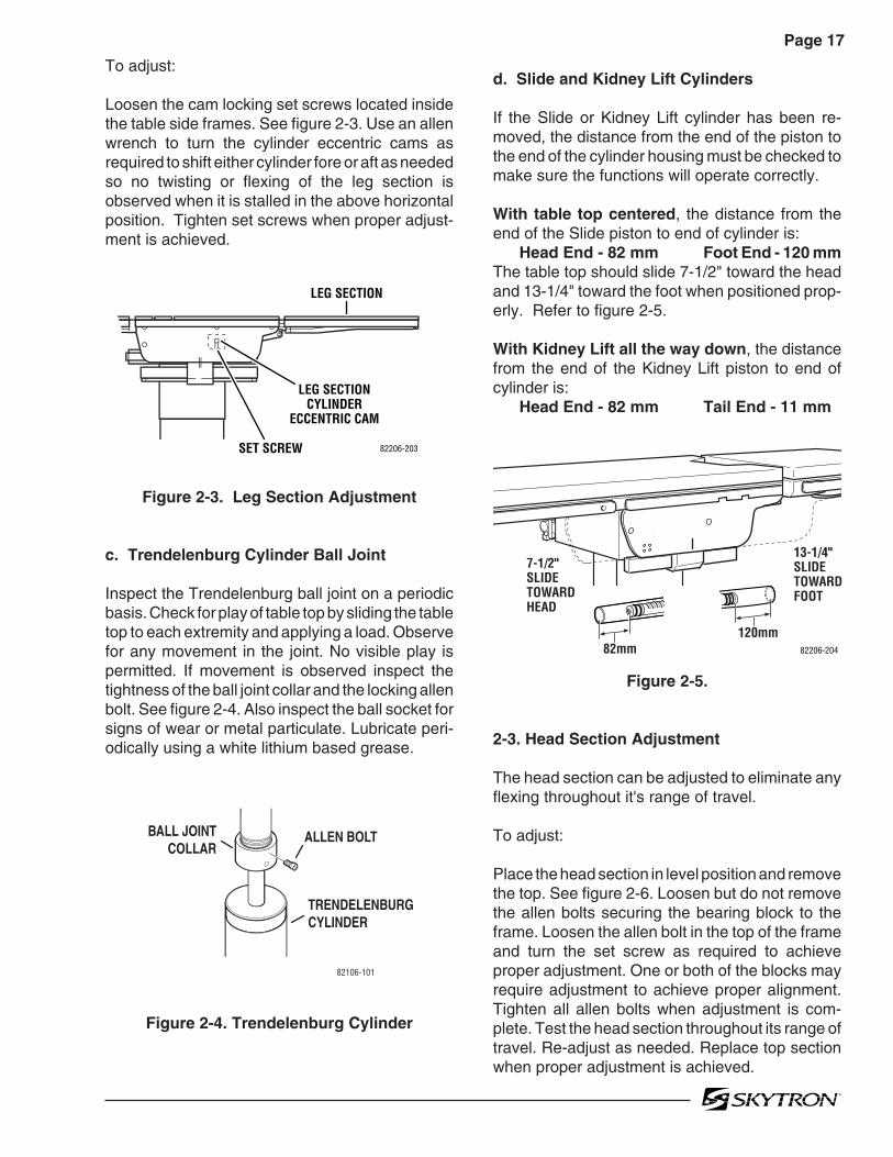
Page 17
To adjust:
Loosen the cam locking set screws located insidethe table side frames. See figure 2-3. Use an allenwrench to turn the cylinder eccentric cams asrequired to shift either cylinder fore or aft as neededso no twisting or flexing of the leg section isobserved when it is stalled in the above horizontalposition. Tighten set screws when proper adjust-ment is achieved.
Figure 2-3. Leg Section Adjustment
c. Trendelenburg Cylinder Ball Joint
Inspect the Trendelenburg ball joint on a periodicbasis. Check for play of table top by sliding the tabletop to each extremity and applying a load. Observefor any movement in the joint. No visible play ispermitted. If movement is observed inspect thetightness of the ball joint collar and the locking allenbolt. See figure 2-4. Also inspect the ball socket forsigns of wear or metal particulate. Lubricate peri-odically using a white lithium based grease.
d. Slide and Kidney Lift Cylinders
If the Slide or Kidney Lift cylinder has been re-moved, the distance from the end of the piston tothe end of the cylinder housing must be checked tomake sure the functions will operate correctly.
With table top centered, the distance from theend of the Slide piston to end of cylinder is:
Head End - 82 mm Foot End - 120 mmThe table top should slide 7-1/2" toward the headand 13-1/4" toward the foot when positioned prop-erly. Refer to figure 2-5.
With Kidney Lift all the way down, the distancefrom the end of the Kidney Lift piston to end ofcylinder is:
Head End - 82 mm Tail End - 11 mm
LEG SECTION
SET SCREW
LEG SECTIONCYLINDER
ECCENTRIC CAM
82206-203
82mm120mm
7-1/2"SLIDETOWARD HEAD
13-1/4"SLIDETOWARD FOOT
82206-204
Figure 2-4. Trendelenburg Cylinder
Figure 2-5.
2-3. Head Section Adjustment
The head section can be adjusted to eliminate anyflexing throughout it's range of travel.
To adjust:
Place the head section in level position and removethe top. See figure 2-6. Loosen but do not removethe allen bolts securing the bearing block to theframe. Loosen the allen bolt in the top of the frameand turn the set screw as required to achieveproper adjustment. One or both of the blocks mayrequire adjustment to achieve proper alignment.Tighten all allen bolts when adjustment is com-plete. Test the head section throughout its range oftravel. Re-adjust as needed. Replace top sectionwhen proper adjustment is achieved.
ALLEN BOLT
TRENDELENBURGCYLINDER
BALL JOINTCOLLAR
82106-101

Page 18
Figure 2-6. Head Section Adjustment
2-4. Slide Roller Adjustment
The pivot pins on the slide rollers are eccentriccams. The rollers can be adjusted if required tomaintain proper top slide operation.
To adjust:
Remove the Seat section top, the hose cover andthe right and left lateral tilt frame covers for accessto the top rollers.
1. Align the table top so the rollers to beadjusted are contacting the slide bars.
2. Loosen the adjustment cam set screw andadjust the roller using an 8mm Allen wrench. Seefigure 2-7. To avoid any possible binding in theslide mechanism, adjust the roller on the oppositeside of the table in the same manner (cam turnedtoward same end of table on each side).
3. Lubricate rollers and slides with white lithiumbased grease.
4. Adjust rollers so top slides smoothly with noup or down movement of the table top.
5. When adjustment is complete, tighten setscrews, replace covers and top section.
Figure 2-7.
2-5. Side Rails
Inspect each of the side rail sections. Make surethat all retaining hardware is tight. Inspect thegravity stops. Make sure that each gravity stopmoves freely. Clean, lubricate or replace as neces-sary. See figure 2-8.
Figure 2-8.
2-6. Casters
Clean and lubricate each of the casters. Removeany debris caught in the casters and old grease.Lubricate using a grease gun and conventionalwheel bearing grease. The casters should rotatefreely providing a smooth movement of the tableduring positioning. Replace worn or defective cast-ers as required.
SLIDEROLLER
8mm ALLENWRENCH
SET SCREW
82206-206
GRAVITYSTOP
SIDERAIL
82106-102
82206-205
ALLENBOLT
ALLENBOLTS
ADJUSTMENTSET SCREW

Page 19
Once the problem has been determined, concen-trate on that particular hydraulic circuit or controlfunction.
Listed below are the hydraulic components thatare common with all hydraulic circuits. If there is aproblem with any of them, it could affect all controlfunctions.
1. Motor/Pump Assembly2. Reservoir3. Pressure Relief Valve4. Certain Oil Lines and Galleys
If there was a problem in the following components,only one control function would normally be af-fected.
1. Mini-Valve2. Slave Cylinder3. Oil Lines
NOTE
Whenever a hydraulic line or compo-nent is replaced, bleed the air out of thelines using the pump pressure beforemaking the final connection. After allconnections are tight, cycle the controlfunction back and forth two or threetimes to purge the remaining air fromthe system.
CAUTION
When installing new "O" rings use hy-draulic oil or white lithium grease tothoroughly lubricate the "O" rings andcylinder. Keep everything clean.
Each complete oil circuit is shown on the followingpages. When troubleshooting a particular function,refer to the appropriate oil circuit diagram and thelist of possible problems.
SECTION III HYDRAULIC TROUBLESHOOTING
3-1. Precautions
Before attempting to troubleshoot any hydraulicproblem on the table, please read through the pre-cautions and notes below.
CAUTION
When disconnecting any of the hydrau-lic lines, fittings, joints, hoses, etc., forthe following control functions, be surethese table surfaces are in their downposition or completely supported.
ElevationBack SectionLeg SectionKidney Lift
When working on the Trendelenburgor lateral tilt hydraulic circuits, be sureto support the table top. When workingon the brake system make sure thebrakes are completely retracted.
WARNING
Failure to follow these precautions mayresult in an uncontrolled oil spray anddamage to the table or personal injury.
3-2. Troubleshooting Notes
When troubleshooting a table malfunction, firstdetermine the following:
1. Does the problem affect all control func-tions?
2. Does the problem affect only one controlfunction?
3. If the problem affects one control function isit in both directions?
4. Is the problem intermittent?
5. Is the problem no movement of a tablesurface or does the table surface lose position?

Page 20
ProblemTable will not elevate properly
Table will not descend properly
Table loses elevation
ReasonPressure Relief Valve Not Set ProperlyLow on OilSpool Valve Not CenteredDefective PumpDefective Mini-ValveDefective Solenoid or WiringDefective Relay Box or Pendant ControlLeaking Cylinder HoseUneven Weight Distribution
Incorrect Speed AdjustmentDefective Check ValveSpool Valve Not CenteredGalled Slider AssemblyDefective Solenoid or WiringDefective Relay Box or Pendant ControlUneven Weight Distribution
Defective Check ValveLeaking Mini-ValveLoose Fittings, Joints, HosesLeaking "O" Ring Inside Cylinder
3-3. ELEVATION DIAGNOSIS CHART
Figure 3-1. Elevation Circuit
SPEED CONTROL
CHECK VALVE
MINIVALVE
MAIN PLUMINGTERMINALCOPPER
LINE
FLEXIBLEHOSE
SECONDARYPISTON O-RING
PRIMARYPISTON O-RING
82206-301

Page 21
ReasonIncorrect Speed AdjustmentSpool Valve Not CenteredDefective Check ValvesLow on OilPinched HoseDefective Mini-ValvePressure Relief Valve Not Set ProperlyDefective Solenoid or WiringDefective Relay Box or Pendant ControlWorn Ball Joint or Retainer Nut
Defective or Dirty Check ValveOil Leakage in CircuitAir Inside CylinderPinched HoseLow on Oil
ProblemTrendelenburg function moves improperly
Trendelenburg function chatters or loses position
3-4. TRENDELENBURG DIAGNOSIS CHART
Figure 3-2. Trendelenburg Circuit
82206-302
SPEEDCONTROL
CHECKVALVE FLEXIBLE
HOSE
MINI-VALVE
INTERNAL OIL RETURN TO RESERVOIR
INTERNALOIL FROM PUMP
COPPERLINE
PLUMBINGTERMINAL
TRENDELENBURGCYLINDER

Page 22
ProblemLateral tilt function moves improperly
Lateral tilt function chatters or loses position
ReasonIncorrect Speed AdjustmentSpool Valve Not CenteredDefective Check ValvesLow on OilPinched HoseDefective Mini-ValvePressure Relief Valve Not Set ProperlyDefective SolenoidDefective Relay Box or Pendant Control
Defective or Dirty Check ValvesOil Leakage in CircuitAir Inside CylinderPinched HoseLow on Oil
3-5. LATERAL TILT DIAGNOSIS CHART
Figure 3-3. Lateral Tilt Circuit
82206-303
LATERAL TILTCYLINDER
FLEXIBLEHOSE
LEFT CIRCUIT
RIGHT CIRCUIT
PLUMBINGTERMINAL
MINI-VALVE
COPPERLINE
INTERNALOIL RETURN
TO RESERVOIR
INTERNAL OILFROM PUMP
CHECKVALVE
SPEED CONTROL
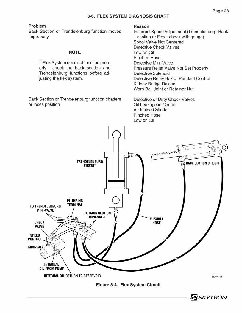
Page 233-6. FLEX SYSTEM DIAGNOSIS CHART
ReasonIncorrect Speed Adjustment (Trendelenburg, Back section or Flex - check with gauge)Spool Valve Not CenteredDefective Check ValvesLow on OilPinched HoseDefective Mini-ValvePressure Relief Valve Not Set ProperlyDefective SolenoidDefective Relay Box or Pendant ControlKidney Bridge RaisedWorn Ball Joint or Retainer Nut
Defective or Dirty Check ValvesOil Leakage in CircuitAir Inside CylinderPinched HoseLow on Oil
ProblemBack Section or Trendelenburg function movesimproperly
NOTE
If Flex System does not function prop-erly, check the back section andTrendelenburg functions before ad-justing the flex system.
Back Section or Trendelenburg function chattersor loses position
Figure 3-4. Flex System Circuit
82206-304
TO TRENDELENBURGMINI-VALVE
TO BACK SECTIONMINI-VALVE
SPEEDCONTROL
CHECKVALVE
PLUMBINGTERMINAL
TRENDELENBURGCIRCUIT
BACK SECTION CIRCUIT
MINI-VALVE
INTERNAL OIL RETURN TO RESERVOIR
INTERNALOIL FROM PUMP
FLEXIBLEHOSE

Page 24
Figure 3-5. Back Section Circuit
3-7. BACK SECTION DIAGNOSIS CHART
ReasonIncorrect Speed AdjustmentSpool Valve Not CenteredDefective Check ValvesLow on OilPinched HoseDefective Mini-ValvePressure Relief Valve Not Set ProperlyDefective SolenoidDefective Relay Box or Pendant ControlKidney Bridge RaisedLoose Retaining HardwareMicroswitch out of adjustmentLoose Table Top
Defective or Dirty Check ValvesOil Leakage in CircuitAir Inside CylinderPinched HoseLow on Oil
ProblemBack Section function moves improperly
Back Section function chatters or loses position
82206-305
BACK SECTIONCYLINDER
DOWN CIRCUITNOTE: ONE SIDE SHOWN FOR CLARITY
UP CIRCUIT
FLEXIBLEHOSE
SPEEDCONTROL
CHECKVALVE
COPPERLINE
MINI-VALVE
INTERNAL OIL RETURN TO RESERVOIR
INTERNALOIL FROM PUMP
PLUMBINGTERMINAL

Page 253-8. LEG SECTION DIAGNOSIS CHART
ReasonIncorrect Speed AdjustmentSpool Valve Not CenteredDefective Check ValvesLow on OilPinched HoseDefective Mini-ValvePressure Relief Valve Not Set ProperlyDefective SolenoidDefective Relay Box or Pendant ControlLoose Retaining HardwareMicroswitch out of adjustmentLoose Table Top
Defective or Dirty Check ValvesOil Leakage in CircuitAir Inside CylinderPinched HoseLow on Oil
ProblemLeg function moves improperly
Leg function chatters or loses position
Figure 3-6. Leg Section Circuit
82206-306
LEG SECTIONCYLINDER
DOWN CIRCUIT
UP CIRCUIT
SPEEDCONTROL
CHECKVALVE
COPPERLINE
MINI-VALVE
INTERNAL OIL RETURN TO RESERVOIR
INTERNALOIL FROM PUMP
PLUMBINGTERMINAL
FLEXIBLEHOSE
NOTE: ONE SIDE SHOWN FOR CLARITY

Page 26
Figure 3-7. Slide Circuit
3-9. SLIDE DIAGNOSIS CHART
ProblemSlide function moves improperly
Slide function chatters or loses position
ReasonIncorrect Speed AdjustmentSpool Valve Not CenteredDefective Check ValveLow on OilPinched HoseDefective Mini-ValvePressure Relief Valve Not Set ProperlyDefective SolenoidDefective Relay Box or Pendant ControlLoose Retaining HardwareMicroswitch out of adjustmentLoose Table Top
Defective or Dirty Check ValveOiI Leakage in CircuitAir Inside CylinderPinched HoseLow on Oil
82206-307
SLIDECYLINDER ASSEMBLY
PISTON
PISTON
SPEEDCONTROL
CHECKVALVE
MINI-VALVE
INTERNAL OIL RETURN TO RESERVOIR
INTERNALOIL FROM PUMP
PLUMBINGTERMINAL
COPPERLINE

Page 27 3-10. KIDNEY LIFT DIAGNOSIS CHART
ProblemKidney Lift moves improperly
Kidney Lift chatters or loses position
ReasonIncorrect Speed AdjustmentSpool Valve Not CenteredDefective Check ValveLow on OilPinched HoseDefective Mini-ValvePressure Relief Valve Not Set ProperlyDefective SolenoidDefective Relay Box or Pendant ControlBypass Valve out of Adjustment
Defective or Dirty Check ValveOiI Leakage in CircuitAir Inside CylinderPinched HoseLow on OilLift Rods Binding
Figure 3-8. Kidney Lift Circuit
82206-308
SPEEDCONTROL
CHECKVALVE
MINI-VALVE
INTERNAL OIL RETURN TO RESERVOIR
INTERNALOIL FROM PUMP
PLUMBINGTERMINAL
FLEXIBLEHOSE
COPPERLINE
KIDNEY LIFTCYLINDER
KIDNEY LIFTCYLINDER
BYPASSVALVE
DOWN CIRCUIT
UP CIRCUIT
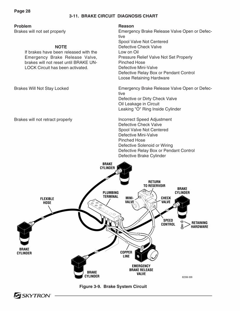
Page 28
Figure 3-9. Brake System Circuit
3-11. BRAKE CIRCUIT DIAGNOSIS CHART
ProblemBrakes will not set properly
NOTEIf brakes have been released with theEmergency Brake Release Valve,brakes will not reset until BRAKE UN-LOCK Circuit has been activated.
Brakes Will Not Stay Locked
Brakes will not retract properly
ReasonEmergency Brake Release Valve Open or Defec-tiveSpool Valve Not CenteredDefective Check ValveLow on OilPressure Relief Valve Not Set ProperlyPinched HoseDefective Mini-ValveDefective Relay Box or Pendant ControlLoose Retaining Hardware
Emergency Brake Release Valve Open or Defec-tiveDefective or Dirty Check ValveOil Leakage in CircuitLeaking "O" Ring Inside Cylinder
Incorrect Speed AdjustmentDefective Check ValveSpool Valve Not CenteredDefective Mini-ValvePinched HoseDefective Solenoid or WiringDefective Relay Box or Pendant ControlDefective Brake Cylinder
BRAKECYLINDER
82206-309
CHECKVALVE
SPEEDCONTROL
MINI-VALVE
PLUMBINGTERMINAL
FLEXIBLEHOSE
BRAKECYLINDER
BRAKECYLINDER
BRAKECYLINDER
EMERGENCYBRAKE RELEASE
VALVE
RETURNTO RESERVOIR
COPPERLINE
RETAININGHARDWARE

Page 293-12. Flexible Hose Identification and Placement
The flexible hydraulic hoses used in the table arenumber coded to aid in the correct placement of the
Figure 3-10. Flexible Hoses
hoses from the plumbing terminal to their respec-tive hydraulic cylinders. Figure 3-10 shows thecorrect placement of the flexible hydraulic hosesand their respective number codes.
MOTOR/ PUMPASSEMBLY
EMERGENCYBRAKE
RELEASE
PLUMBINGTERMINAL
ELEVATION
1
240
600
L.F.
750
L.R.
670
R.R.
600
R.F.
TO BRAKE CYLINDERS
PRESSURERELIEFVALVE
ASSEMBLY
MINI-VALVES
1 32 4
5 76
98 10
11 132
7
1 5
2 4
97
6
3
105140115
140130140
150135120
100 100 135100 120
BRAKEMINI-VALVEASSEMBLY
400
11
KIDNEYCYL.LEFT
KIDNEYCYL.
RIGHT
10
90
LEG SECTION
9
8
LEG SECTION
9
8
150
800
240
80
1900
2060
4 5TILT
BACK SECTION
7
6
BACK SECTION
7
6
1200
2210
11
2600
2450
10
13
SLIDECYLINDER
21702170
2400
2500
1150
1000
2300
8
1470
1370
2
3
TRENDELENBURG
COMPENSATINGVALVE
1270
12
130
12
14
360
300
40
40
80
14
3501B
31.6280
DCPUMP 230
80240
82506-310
12
13

Page 30
3-13. Kidney Lift System
The Kidney Lift cylinders are connected in series sothat both cylinders operate simultaneously.
Hydraulic pressure on one side of the lead pistoncauses the piston to move. The piston movementforces the hydraulic fluid on the other side of thepiston through the system to the other cylinder.This simultaneously activates the other piston. Abypass valve is connected to the right cylinderassembly for initial setup and adjustment of thekidney lift system. Refer to figure 3-9 for valvelocation. Use the following procedures to bleed oradjust the system if needed.
a. Bleeding the System
If the hydraulic lines or cylinders have been discon-nected from the kidney lift system for any reason,use the following procedure to bleed the air fromthe system.
1. Remove the kidney lift top section and beginthe procedure with both pistons in the down posi-tion (chambers A & C) as shown in figure 3-11.
2. Make sure the bypass valve is closed (valvescrew tight) and activate "KIDNEY DOWN". Thehydraulic fluid will fill cavity "D" as shown in figure3-11.
Figure 3-11.
Figure 3-12.
3. Open the bypass valve by loosening thescrew in the bottom of the valve and activate"KIDNEY UP". Hydraulic fluid fills cavity "A" andpushes the piston into cavity "B". The open valveallows a path for air to escape from cavity "B"without affecting the piston in "C". See figure 3-12.
82206-311
LEFT CYLINDER
RIGHT CYLINDER
D C
B A
BYPASS VALVE (closed)
KIDNEY LIFTDOWN
82206-312
LEFT CYLINDER
RIGHT CYLINDER
D C
B A
BYPASS VALVE (open)
KIDNEY LIFTUP

Page 31
Figure 3-13.
5. Repeat steps 3 and 4 as needed to removeany remaining air in the system.
6. With both pistons in the full down position,activate "KIDNEY DOWN" to apply full systempressure and close the bypass valve (tighten thescrew).
4. Leave the bypass valve open and activate"KIDNEY DOWN". Hydraulic pressure keeps thepiston in chamber "C", the hydraulic fluid passesthrough the bypass valve and fills cavity "B" push-ing the piston into cavity "A". See figure 3-13.
b. Cylinder Adjustment
If either of the kidney lift cylinders reaches the endof the down stroke before the other one, an adjust-ment is needed. Use the following procedure toadjust the system.
1. If the right side bottoms out before the leftside, open the bypass valve and activate "KIDNEYDOWN" to align the cylinders.
2. If the left side bottoms out before the rightside, activate "KIDNEY UP" to raise the cylinders.When the cylinders are at the full up position, openthe valve and activate "KIDNEY UP" to align thecylinders. Close the valve before lowering thecylinders.
3. When the adjustment is complete, makesure the cylinders are completely down, activate"KIDNEY DOWN" and tighten the screw to closethe valve.
82206-313
LEFT CYLINDER
RIGHT CYLINDER
D C
B A
BYPASS VALVE (open)
KIDNEY LIFTDOWN

Page 32
4-1. General
The complete electrical system (with the excep-tion of the hand-held pendant control and the returncircuit micro-switches) is contained within the baseof the table. The pump motor and the hydraulicvalves are controlled electrically with the pendantcontrol.
The electrically operated functions are as follows:
- ELEVATION - Up and Down
- TRENDELENBURG - Head up and down
- LATERAL TILT - Right and left
- BACK SECTION - Up and Down
- LEG SECTION - Up and Down
- TOP SLIDE
- FLEX / REFLEX
- KIDNEY LIFT - Up and down
- LEVEL - Return to level
- BRAKE UNLOCK - Brake release
The power requirements are 120 VAC, 60 Hz. Themain power on-off switch is an enclosed DPSTcircuit breaker type and the power cord is a three-wire, fifteen foot long, removable, UL listed cordwith a three-prong hospital grade plug.
4-2. Components
Refer to figure 4-1 for the relationship of the elec-trical components.
a. Wires, Connectors, Switches, Fuse - Theseprovide the path for the various electrical circuits.
b. Relay Box - Contains the step down trans-former, full wave rectifier, micro-processor andrelay switches. The relay switches are activated bythe pendant control signal to the micro-processorand in turn energize the solenoids.
c. Hand-Held Pendant Control - Containscircuit board mounted switches and a micro-pro-cessor which activate the relay box. Operates on5 VDC.
d. Solenoids - These electrically open andclose the hydraulic ports of the mini-valve to directthe fluid to the correct cylinders. They operate on24 volts.
e. Motor/Pump Assembly - 24 VDC motor withinternal thermal protection.
SECTION IV ELECTRICAL SYSTEM

Page 33
Figure 4-1. 3501B Electrical Circuit Block Diagram
82206.401
MINI-VALVES
CN1B
CN1A
CN2
SOLENOID COILS 24VDC
HN1 HN2
HN4
HN3
MAINPOWERSWITCH
BATTERYINDICATOR
FOOTCONTROL
CONNECTOR
15ACIRCUIT
BREAKER
TWIST-LOCK POWER CORD
RELAY BOX
BUZZER
CN3
CN8
HN5HN9
CN11 CN10
CN4
PUMP
CN7
HN8
TRANSFORMER
CAPACITOR/RECTIFIER BOX
PENDANTCONTROL
BATTERIES
TM1
TM2
BASECONNECTOR

Page 34
5-1. General
The battery table components operate on 24VDC.The internal charging system also incorporates thecomponents to transform the 120VAC input to24VDC output to the components.
5-2. Troubleshooting Notes
The basic operation of each component will bedefined along with a figure and an explanation onhow to check it out.
Certain defective components could cause theentire table to stop functioning or only one controlfunction to stop. It would depend on what part of thecomponent failed. Other defective componentswould only cause one control function to stop.
The following defective components could causeall control functions to be affected:
a. Motor/Pump Assemblyb. Main Switch Circuit and Wiringc. Pendant control
The following defective components could causeall control functions to be affected or only onecontrol function:
a. Relay Boxb. Pendant Controlc. Auxiliary Switches
The component listed below would only affect onecontrol function:
Solenoid
When troubleshooting an electrical circuit, start atthe problem and work back to the power source.
NOTE
•Battery table troubleshooting should be-gin by switching the operating mode. Forexample; if a function fails in the AC120Vmode, switch to the BATTERY mode. Ifthe function now operates, the problem isprobably located between the power cordand the relay box. If the function also failsin battery operation, use the auxiliaryswitches. If the function now operates,the problem is probably in the pendantcontrol, connectors or wiring from thependant control to the relay box.•All connector pins are numbered usuallywith very small numbers.
5-3. Main Switch
The main power supply, 120 VAC, 60 HZ, comesin through the power cord and through thePower Switch. The Power Switch opens bothlines when in the "OFF" position. The PowerSwitch is also a 10 Amp circuit breaker that is usedto protect the complete electrical system.
a. Main Switch Test
The following test will determine if line voltage isapplied to connector HN1, which in turn wouldsupply 120VAC power to the table.
1. Plug the power cord into the 120VAC supply(wall receptacle) and turn the main switch ON.
2. Disconnect connector HN1. See figure 5-1.Leave all other connectors connected.
CAUTION
Line voltage (120 VAC) will be mea-sured in this test. Do not touch uninsu-lated connector pins or meter test leads.
3. Use an AC voltmeter capable of measuring120 VAC and measure the voltage between pins 1and 2 (black and white wires) located in connectorHN1. See figure 5-1. You should receive linevoltage 120 VAC.
Figure 5-1. Connector HN1 Test
SECTION V ELECTRICAL TROUBLESHOOTING
82206-501
BLACK
WHITE
2
1
HN
1

Page 35
b. Test Results
If the correct voltage is obtained, everything isgood up to this point and the problem would haveto be in another area. If you do not receive thecorrect measurements, the problem would haveto be in the wires, Power Switch, Power Cord, ormain electrical Power Cord connector (3 pin twistlock connector).
Check the continuity from the power cord baseconnector, through the switch and wiring to con-nector HN1. Remove the power cord, disconnectHN1 (black and white wires), and test as shown infigure 5-2.
a. Battery System Test
1. Disconnect the main power cord and usinga DC voltmeter, test each individual battery at itsterminals. Meter should read 12VDC ± 1V.
2. To accurately test the batteries, they must betested under a full load. Disconnect the main powercord and make sure all other connectors are con-nected.
3. Turn BATTERY power ON and elevate thetable to its full up position.
4. Continue to press the TABLE UP button on thependant control so that the pump motor continues torun and using a DC voltmeter, check the voltage dropof each battery individually. See figure 5-3.
5. Meter should read 12VDC ± 1VDC.
Figure 5-2. Base Connector to HN1 Continuity Test
5-4. Batteries
The BATTERY operating mode is powered by two12 volt batteries connected in series to provide the24 volt operating power.
The battery system voltage should be 24VDC at arange of 22VDC to 26VDC. If the battery chargelevel falls below 23.5 volts the BATTERY operationindicator on the pendant control will blink indicatingthat the batteries require recharging. The built-incharging system automatically keeps the batteriesat the proper charge level when the AC120V oper-ating mode is ON. The charging system will oper-ate while the table is being operated in the AC120Vmode.
Figure 5-3.
b. Test Results
A reading of 11 volts or below indicates the batteryneeds charging.
After batteries have been fully charged, repeat thefull load test. If either battery's voltage drops below11VDC it should be replaced.
82206-502
BLACK
WHITEHN1
BASECONNECTOR
2
82206-503
BATT1 BATT2
+
-
+
-

Page 36
b. Test Results
If the correct voltage is obtained, everything isgood up to this point and the problem would haveto be in another area.If you do not receive the correct measurements,the problem may be in the wires, connectors, ortransformer. The transformer is located in the rearof the base under the stainless steel base cover.The stainless steel cover will have to be discon-nected and lifted from the base for access to thetransformer for further testing.
c. Capacitor / Rectifier Unit Test
1. Make sure all connectors are connected,connect the power cord and turn AC120V operationON. Test connectors HN2 and HN3 using a voltme-ter. See figure 5-5.
5-5. Capacitor / Rectifier / AC120V Transformer
The Capacitor / Rectifier Unit contains the batterycharging system as well as the components forAC120V operation (except the transformer).
a. Transformer Test
1. Confirm 120VAC input at HN1 using MainSwitch test in 5-3a.
2. Connect HN1, disconnect HN2 (brown andred wires) and using an AC voltmeter, test thetransformer output at HN2. See figure 5-4.
3. Meter should read 22VAC.
Figure 5-4. Connector HN2 Test
Figure 5-5. Connector HN3
2. Test connector HN2 at pins 1 (red) and 3(brown). Meter should read AC23V.
3. Test connector HN3 at pins 1 (purple) and 2(black, ground). Meter should read DC30V.
4. Test connector HN3 at pins 5 (orange) and2 (black, ground). Meter should read DC27V.
82206-504
BROWN
RED
HN2
3
1
82206-505
RED
BROWNHN2
HN3 1
25
2
HN3 CONNECTOR WIRE COLORS
1. PURPLE2. BLACK3. YELLOW4. GRAY5. ORANGE

Page 37
e. Charging Indicator Test
Charging Indicator contains 10 LEDs, 3 red, 4yellow and 3 green.
All Indicators illuminated indicates full charge.Indicators flash when charging is in process.The following list shows the battery charge level asindicated by the lighted LED's:
3 green 100% -Fully charged2 green 89%1 green 78%4 yellow 67%3 yellow 56%2 yellow 45% -Needs Charging (BATT
indicator on pendant will flash)1 yellow 34% -Needs Charging3 red 23% -Needs Charging
(poor performance)2 red 12% -Needs Charging
(intermittent performance)1 red 1% -Needs Charging
(inoperable)
Main Power Switch must be ON and power cordattached and plugged into outlet for charging sys-tem to operate.
Test output from relay box at CN3 pin 11 commonand pin 1 (lowest charge) meter should read approx.1.8 VDC. See figure 5-6.
Figure 5-6
5-6. Pendant Control
The Pendant Control is part of the solid state, multi-plex, logic control system. The pendant controlcontains illuminated, circuit board mounted switchesand a micro processor. The encoded output from thependant control is serial bit stream logic.
The output signal is transmitted to the micro pro-cessors in the relay box where the logic is decodedand the appropriate relays for the selected functionare activated.
Pendant Control troubleshooting should begin byswitching the operating mode of the table. Forexample; if a function fails when operating the tablein the AC120V mode, switch to the BATTERYmode. If the function now operates, the problem isnot the pendant control and probably is a problemlocated between the power cord and the relay box.If the function also fails when in battery operation,use the auxiliary switches to operate the function.If the function now operates, the problem is prob-ably in the pendant control, connectors or wiringfrom the pendant control to the relay box.
d. Test Results
If you do not receive the correct readings, theconnectors, wires, or the Capacitor/Rectifier Unitmay be defective.
NOTE
Normal charging time for a fully dis-charged battery is approximately 8hours.
82206-506
1
11
CN3

Page 38
a. Pendant Control Test
There are some serviceable components withinthe Pendant Control. The cord is detachable andcan be tested for continuity between the pins on theconnectors. Use the following procedure to test thependant control cord. See figure 5-7.
Figure 5-7. Pendant Control Test
Disconnect the cord from the table connector andfrom the pendant control connector and using anohmmeter, test the continuity between the corre-sponding pins in the connectors.
b. Test Results
If you do not receive the correct readings, thewiring or connector pins may be faulty.
Figure 5-8. Table Connector Continuity Test
d. Test Results
If the correct readings are not obtained, test thewiring from the table connector HN8 to connectorHN7 (located behind the Pendant Connector Hous-ing) and from connector CN7 to HN7. Disconnectconnector HN7 and using an ohmmeter, test thecontinuity between the corresponding pins in con-nectors HN7 to CN7 and HN7 to HN8. Refer tofigure 5-8.
If the correct readings are obtained, this part ofthe circuit is okay and the problem may be thePendant Control or the Relay Box. ContactSKYTRON if all tests performed indicate that theproblem is located in the Pendant Control.
c. Table Connector HN8 Test
If correct readings are received, test the wiring fromthe table connector to connector CN7 at the RelayBox. Disconnect connector CN7 from the RelayBox and using an ohmmeter, test the continuitybetween the corresponding pins in connectorsCN7 and the table connector HN8. See figure 5-8.
82306-507
Test LeadsBase Conn.
Pin1234
1627
567
543
Pend. Conn.Pin
Base Conn.Pin
Pend. Conn.Pin
BLACK 1
GREEN 4RED 3
WHITE 6
2 BROWN
5 BLUE
7 YELLOW
1 BLACK3 RED4 GREEN7 YELLOW
2 BROWN
6 WHITE
BLUE 5
BASE END PENDANT END
82306-508
CN7
HN81
1
LT. GREEN/WHITE
CN7 CONNECTOR HN8 CONNECTOR
1234567
1234567
LT. GREEN / WHITELT. GREENGREEN / BLACKGREEN / REDGRAYGRAY / WHITE- - -

Page 39
5-7. Auxiliary Switches
The following tests will determine if the auxiliaryswitches are functioning properly.
a. Switch Test
Disconnect connector CN2 at the Relay Box andusing an ohmmeter check for continuity at theconnector pins (pin 1A common) while activatingthe appropriate switch. See figure 5-9. Metershould read 0 ohms.
Figure 5-9. Auxiliary Switch Connector CN2
Figure 5-10. Auxiliary Switch Test
82306-509
1
SW1CN2
TABLE UP
TABLE DOWN
TREND
REV TREND
TILT RIGHT
TILT LEFT
BACK UP
BACK DOWN
KIDNEY DOWN
BRAKE LOCK
LEG UP
LEG DOWN
PUMP MOTOR
GROUND
SW2
SW3
SW4
SW5
SW6
2
3
4
5
6
7
8
9
10
11
12
13
14
15
16
PIN NO
1 (A1)2 (B1)3 (A2)4 (B2)5 (A3)6 (B3)7 (A4)8 (B4)
RedGreen / White
BrownYellowOrangeGreen
Brown / WhiteBlue
9 (A5)10 (B5)11 (A6)12 (B6)13 (A7)14 (B7)15 (A8)16 (B8)
----
BlackBlue / White
GrayYellow / White
Red / WhiteOrange / White
COLOR PIN NO COLOR
CN2
B8/B2 B8/A3 B8/A4 B8/A1 B8/A7 B8/B6
B8/A2 B8/B3 B8/B4 B8/B1 B8/B7 B8/A6
REVTREND
TILTRIGHT
BACKUP
TABLEUP
LEGUP
BRAKELOCK
TREND TILTLEFT
BACKDOWN
TABLEDOWN
LEGDOWN
KIDNEYDOWN
1(A1)
6(B3)
82306-510
b. Test Results
If proper meter readings are not received, test theindividual switches as necessary. Using an ohmme-ter, test the operation of an individual switch with the(+) test lead at the center terminal of the switch andthe (-) test lead at the terminal opposite the directionof the switch actuation. Refer to figure 5-10. Metershould read 0 ohms. If the switches check out, theproblem would have to be in the wires, the switchcircuit board or connector CN2.

Page 40
5-8. Relay Box
The power supply is directly connected to the relaycontacts. When these contacts are closed, 24volts is supplied to the solenoids which are mountedon the hydraulic mini-valves. One relay is used tosupply power to the pump/motor and is alwaysactivated no matter what control function is se-lected. The brake locking circuit relay is alsoactivated when any control function other thanBRAKE UNLOCK is initially selected.
Also, inside the relay box is a step-down trans-former and full-wave rectifier which decreases thevoltage to 5-6 volts. This low voltage potentialcontrols the relays by the use of the hand-heldpendant control buttons. Basically the relays en-able a 5-6 volt potential to control the 24 volt circuit.
The following tests will determine if the relay box isfunctioning correctly.
a. Checking Relay Box Input Power
1. Connect power cord to table. Plug the powercord into the 120VAC supply (wall receptacle).Disconnect connector CN4, leave all other connec-tors connected.
2. Using a DC voltmeter, test input power forboth the BATTERY and AC120V operating modes.See figure 5-11. Meter should read approximately24 -28 volts.
b. Test Results:
If you do not receive the correct meter readings,the problem is in the input wiring, connectors orcomponents. If the correct readings are obtained,proceed to the next step.
Figure 5-11. Relay Box Input
c. Checking Output to Pump
1. Make sure all connectors are connected andactivate the AC120V operating mode. See figure 5-12.
82306-511
1-RED (+)2-BLUE (-)
2
1CN4
BATTERY MODE TEST (main power OFF)
5-PURPLE (+)6-BLACK (-)
CN4
AC120V MODE TEST (main power ON)
CONNECTOR CN4 COLOR CODE
123456
REDBLUEREDBLACKPURPLEBLACK
7 8 9101112
WHITEWHITEYELLOWGRAYORANGE - - -
6
5
HN4
82306-517
1
2
Figure 5-12. Output to Pump
2. Test HN4 at pin 1(+) and pin 2(-) with a DCvoltmeter. Meter should read approximately 24-28volts when any function button is activated. If novoltage is present, use an ohmmeter to test thecontinuity from HN4 to CN4 (red and black wires).

Page 41
Figure 5-13. Solenoid Output Connectors
NOTE
•Before deciding the relay box is de-fective, check the wires and pins in theconnector blocks to make sure theyare not loose or making a bad connec-tion with their mate.•If the battery power is ON and no tablefunctions have been activated for 3hours, the power off circuit will interruptthe battery power.
f. Checking Output to Pendant Control
The output to the Pendant Control can not betested without specialized equipment. If all testshave been conducted and it appears that the RelayBox is faulty, contact SKYTRON.
d. Checking Output to Solenoids
This test checks the voltage that is used toenergize the solenoids.
1. Activate either BATTERY or AC120V oper-ating mode.
NOTE
•The Brake Lock function is activatedby pressing any function button (exceptBRAKE UNLOCK). A timer in the RelayBox allows continuous output for about7 seconds. If the brakes are alreadylocked, no output is provided.
•The BRAKE UNLOCK button activatesanother timer in the relay box whichallows continuous output for the brakerelease function for approximately 7seconds. If the brakes are alreadyreleased (using the BRAKE UNLOCKbutton) no output is provided.
2. Test connectors CN1A and CN1B from theback while attached to the relay box. All connec-tors should be connected.
3. Activate each of the pendant control buttonsand measure the output voltage for the corre-sponding connector pins with a DC voltmeter. Seefigure 5-13. Meter should read 24 volts.
e. Test Results:
If you do not receive the correct meter readings, therelay box is defective and should be replaced.
82306-512
CN1A
CN1B
CN1A CONNECTOR
FUNCTION PINS
Table UpTable DownTrendelenburgRe. TrendelenburgTilt RightTilt LeftReflexFlex
1 - 23 - 45 - 67 - 89 - 1011 - 1213 - 1415 - 16
CN1B CONNECTOR
FUNCTION PINS
Back UpBack DownSlide To FootSlide To HeadKidney DownKidney UpLeg UpLeg DownBrake SetBrake Unlock
1 - 23 - 45 - 67 - 89 - 1011 - 1213 - 1415 - 1617 - 1819 - 20

Page 42
Figure 5-15.
c. CN4 to Capacitor / Rectifier Unit Test
1. Disconnect connectors CN4, and HN3.Leave all other connectors connected.
2. Using an ohmmeter, test for continuitybetween pins of CN4, and HN3. See figure 5-16.
Figure 5-16. CN4 and HN3
HN4
CN41 3
WIRE COLOR / PIN NUMBER CODES
HN4 CN43478
REDBLACKWHITEWHITE
1234
82306-514
PIN TEST COMBINATIONS
HN3 CN4569
1011
-----
12345
82306-515
CN4HN3
1
5
Figure 5-14.
NOTE
The 15 amp battery protection circuitbreaker is in the line between CN4 pin1 and the battery connector. Test thecontinuity of the circuit breaker if cor-rect meter reading is not received.
b. CN4 to Pump Test
1. Disconnect connectors CN4 and HN4. Leaveall other connectors connected.
2. Using an ohmmeter, test for continuitybetween the pins of CN4 and pins on HN4. Seefigure 5-15.
82306-513CN4
(+) RED(-) BLUE
12
5-9. Main Wire Harness Continuity Tests
If correct meter readings are not received in testsbetween components, before replacing the com-ponents, test the Main Wire Harness to be sure allconnectors and wires are making a good connec-tion.
a. CN4 to Batteries Test
1. Disconnect connectors CN4 and the (+) and(-) connectors from the batteries. Leave all otherconnectors connected.
2. Using an ohmmeter, test for continuitybetween pin 1 of CN4 and battery (+) connector.Also test between pin 2 of CN4 and battery (-)connector. See figure 5-14.

Page 43
5-10. Solenoids
The solenoids are energized by 24 volt potentialthat is controlled by the relay box. The solenoidwindings are protected from excessive heat byan internal thermal fuse that will open afterapprox. 7 minutes of continuous operation. Thesolenoid must be replaced if the internal thermalfuse has been blown. The solenoids are mounteddirectly on either side of the hydraulic mini-valvesand push the spool valve in one direction or theother depending upon which solenoid is activated.
a. Solenoid Test
The resistance of the solenoid coil can bechecked out using an ohmmeter R x 1 scale.
1. Disconnect connectors CN1A and CN1B.Measure the resistance between the two pins atthe connector for the solenoid in question as shownin figure 5-17. Polarity of meter leads is notimportant.
2. The meter should read approximately 16ohms at room temperature.
3. Measure the resistance between eitherpin and ground.
4. Meter should read infinity.
b. Test Results:
If the solenoid does not check out with the meter,it is more than likely defective and must bereplaced.
Figure 5-17. Solenoid Test
82306-516
ELEVATION
Up
Down
TREND.
Trend
ReverseTrend.
LATERALTILT
Right
Left
FLEX
Reflex
Flex
BRAKE
Unlock
Lock
BACKSECTION
Up
Down
Down
Up
KIDNEY
Up
Down
SLIDE
Foot
Head
LEGSECTION
1 2 5 6
CN1A9 10 13 14 1 2 15 16 11 12 19 20
3 4 7 8 11 12 15 16 3 4 13 14 9 10 17 18
5 6
7 8
CN1B
CN1A CN1B
1
2
19
20
17
18
15
16
13
14
11
12
9
10
7
8
5
6
3
4
1
2
CN1B
1
2
15
16
13
14
11
12
9
10
7
8
5
6
3
4
1
2
CN1A
BLUE DOT

Page 44
Figure 5-18. Motor Input Voltage
NOTE
If the pump has been activated continu-ously for 1-1/2 to 2 minutes, the thermalrelay will interrupt the power to thepump.
b. Thermal Protector Test
The Thermal Protector is built in to the pump motorand is used to interrupt the current flow to the pumpmotor to protect it from possible damage due tooverheating.
NOTEWhenever there are several compo-nents of the same type, a defectiveunit can also be detected by substi-tuting a known good unit or wire con-nector. In some cases this may befaster than using a multi-meter.
5-11. Motor/Pump Assembly
The hydraulic pump motor is a thermally protected24 volt DC electric motor. The oil pump unit isattached to the bottom of the motor and is a geartype displacement pump with a pumping capacityof .4 liter per min. The Motor/Pump Assembly ismounted on insulators in the base of the table.
a. Motor/Pump Test
1. Make sure all connectors are connected andactivate the AC120V operating mode. See figure5-18.
2. Test HN4 at pin 1(+) and pin 2(-) with a DCvoltmeter. Meter should read approximately 24-28volts when any function button is activated. If novoltage is present, use an ohmmeter to test thecontinuity from HN4 to CN4 (red and black wires).
1. Turn OFF both BATTERY and AC120Voperating modes.
2. Use an ohmmeter to test for continuitybetween terminals 3 and 4 on the connector HN4.See figure 5-19.
Figure 5-19. Thermal Protector
3. The Thermal Relay should reset itself afterapproximately one minute.
4. The Thermal Relay should activate after 1-1/2 to 2 minutes of continuous pump operation.
c. Motor Resistance Test
The motor can be statically checked for resistanceusing an ohmmeter. This test is not 100% accuratebecause you are checking the motor with very lowvoltage from the meter and without any load.
1. Using an ohmmeter R x 1 scale, measure theresistance between the pins 1 and 2 of HN4. Seefigure 5-20.
2. The meter should read 1 to 2 ohms at roomtemperature.
3. Measure the resistance between either pinand ground.
4. Meter should read infinity.
Figure 5-20. Motor Connector HN4
d. Test Results:
If you do not receive the correct meter readings, themotor or wiring is defective.
HN4
82306-517
1
2
82306.518
HN4
3
4
82306.519
HN4
1
2

Page 45
5-12. Return-to-Level / Positioning Inhibit Micro-Switches.
The return-to-level feature is activated by a singlebutton on the pendant control and automaticallylevels the major table functions, lateral tilt, Trende-lenburg, back section, and leg section.
The kidney lift has a back section-up inhibit switchto prevent the table back section from damagingthe kidney lift when the lift is raised. The backsection still has the capability to be lowered andraised, but will not raise more than 45° abovehorizontal until the kidney lift is completely down. Ifthe back section is raised more than 45° abovehorizontal, the system will not allow the kidney lift tobe raised. An audible alarm will sound if the kidneylift inhibit switch is activated and either function isactivated - raising back section when Kidney lift isup or raising kidney bridge when back section isabove horizontal.
The slide function has inhibit switches to preventdamage to the back and leg sections. If the backsection is below horizontal the top will not slidetoward the foot end. If the leg section is loweredmore than 45° below horizontal the top will not slide
Figure 5-21.
toward the head end. Likewise, if the top is slidtoward the foot end, the back section will not gobelow horizontal. If the top is slid toward the headend, the leg section will not go more than 45° belowhorizontal.
The return-to-level / positioning inhibit system con-sists of 15 micro-switches, 3 electrical connectors,2 terminal strips and the related wiring. The micro-switches are mounted on or adjacent to the functionthey control and are wired for normally open ornormally closed operation. The micro-switches areeither cam or lever actuated and can be adjusted atthe individual switch mounting brackets. Propermicro-switch operation depends on all top sectionsbeing properly secured. Check top section fasten-ers.
The micro-switches operate on low voltage, andcontrol the function circuits (pump/motor and ap-propriate solenoid valves) when activated by thependant control LEVEL button.
The micro-switches are wired to the relay boxthrough a riser cord and to the 26 pin connectorCN10. See figure 5-21 for switch location andidentification.
82306-520
CS-5
CS-3
CS-4
NS-7
NS-1
NS-2
NS-4
NS-3
CS-2CS-1
HEAD SECTION
NS-1NS-2NS-3NS-4NS-5
TRENDELENBURGREVERSE TRENDELENBURGTILT LEFTTILT RIGHTBACK-DOWN TO LEVEL/SLIDE INHIBIT
NS-6NS-7CS-1CS-2 CS-3
BACK-UP TO LEVELLEG-DOWN TO LEVELSLIDE/LEG-DOWN INHIBITSLIDE/BACK-DOWN INHIBIT KIDNEY/BACK 45º UP INHIBIT
CS-4CS-5
LED-DOWN 45º/SLIDE INHIBITBACK-UP 45º/KIDNEY-UP INHIBIT
FOOT SECTION
NS-6
NS-5

Page 46
NOTE
It is normal for the back section to moveup if the LEVEL button is pushed whenconnector CN10 is disconnected fromthe relay box.
All of the micro-switches are connected to the relaybox via a wiring harness and the micro-switch risercord using connectors CN10, HN10, HN11 andterminal strips TM1 and TM2. The terminal stripsare located under the hose cover on the top of theelevation column. Connectors HN10 and HN11are located under the slider shroud in the samearea as the hydraulic hoses. Connector CN10plugs into the relay box and is the most convenientlocation to make circuit continuity checks. Seefigure 5-22 for connector pin locations.
Figure 5-22. Return / Inhibit Micro-Switch Test
5-13. Micro-Switch Troubleshooting
If a problem is suspected in the return / positioningcircuits, disconnect the connector CN10 from theRelay Box to eliminate the circuits. Ensure that alltable functions operate properly using the PendantControl. If the functions do not work properly usingthe Pendant Control, refer to the appropriate testsection and make all needed repairs before work-ing on the return circuits.
82306-521
1
2
NS-1
CN10
1
2
3
4
5
6
7
8
9
10
11
12
13
14
15
16
17
18
19
20
21
22
23
24
25
26
(TM1)
(TM1)NS-2
2
4
6
CS-4
CS-2
CS-5
4
5
7
NS-4
NS-6
3NS-3
NS-5
NS-7
CS-1
CS-3 5
1
6
3
8
8
(TM1)
(TM1)
(TM1)
(TM1)
(TM2)
(TM2)
(TM2)
(TM2)
(TM2)
(TM2)
(TM2)
(TM1)
(TM1)
WHITE
BLUE
YELLOW
GREEN
RED
RED/WH.
BROWN
ORANGE
ORANGE/WH.
LT. BLUE
PINK
PURPLE
BLACK
BLACK/WH.
BROWN/WH.
LEGEND
TM1
TM2

Page 47
a. Switch Test
Turn Main Power ON, lock the table brakes, andplace the table top sections in a level position withthe Kidney Lift down. Disconnect connector CN10from the relay box and using an ohmmeter, test thewiring and switch operation at the appropriate pinnumbers for the micro-switch in question as shownin figures 5-23 through 5-30.
NOTE
Be sure to isolate the circuit when mak-ing continuity checks.
NOTE
If you do not receive the proper continu-ity results at connector CN10 it does notnecessarily mean the micro-switch isdefective. There could be a problemwith the riser cord between connectorCN10 and terminal strips TM1 andTM2, or in the wiring from the switch toconnector. Further tests will have to bemade to determine the exact problem.
Figure 5-23. Trendelenburg Return Switches
82306-522
NCWHITE
LIGHT BLUEBLUE
WHITE
LIGHT BLUE
BLUECOM NCNO
COM
HEAD-DOWN TO LEVEL / TEST AT PINS 1 & 23
NS-1 TRENDELENBURG
Table Position
LevelHead-UpHead-Down
Switch Position
OpenOpenClosed
Meter Reading
InfinityInfinity0
HEAD-UP TO LEVEL / TEST AT PINS 2 & 23
NS-2 REVERSE TRENDELENBURG
When table is in Trendelenburg Position,NS-1 brings the top back to level.
When table is in Reverse Trendelenburg Position,NS-2 brings the top back to level.
Table Position
LevelHead-UpHead-Down
Switch Position
OpenClosedOpen
Meter Reading
Infinity0Infinity
NS-1
NS-2
(CN10)
NOTM1-1
TM1-5
TM1-2
1
23
2

Page 48
Figure 5-25. Back Section Return Switches
NOTE
When CN-10 is disconnected, Back-Down function will not operate.
Figure 5-24. Lateral Tilt Return Switches
82306-523
TEST AT PINS 3 & 23
NS-3 LATERAL TILT-LEFT
Table Position
LevelTilt-RightTilt-Left
Switch Position
OpenOpenClosed
Meter Reading
InfinityInfinity0
TEST AT PINS 4 & 23
NS-4 LATERAL TILT-RIGHT
Table Position
LevelTilt-RightTilt-Left
Switch Position
OpenClosedOpen
Meter Reading
Infinity0Infinity
NS-4 NS-3
NC NCCOM COMNO
YELLOW
LIGHT BLUE
GREEN
YELLOWLIGHT BLUE
GREEN
(CN10)TM1-3
TM1-5
TM1-4
3
23
4
NO
When table is in Tilt-Left Position,NS-3 brings the top back to level.
When table is in Tilt-Right Position,NS-4 brings the top back to level.
82306-524
TEST AT PINS 5 & 24
NS-5 BACK SECTION DOWN
Table Position
LevelBack-DownBack-Up
Switch Position
ClosedOpenClosed
Meter Reading
0Infinity0
TEST AT PINS 5 & 6
NS-6 BACK SECTION UP
Table Position
LevelBack-DownBack-Up
Switch Position
OpenOpenClosed
Meter Reading
InfinityInfinity0
NS-5
NCCOM
RED
PINK
RED
PINK
NO
When the Back Section is Down, NS-5 brings the Back SectionUp to level and will not allow Top Slide toward foot.
When the Back Section is Up,NS-6 brings the Back Section Down to level.
TM1-6
TM1-8
5
24
NS-6
NC COM
RED/WHITE
RED
RED/WHITE
RED
NO
TM1-7
TM1-6
6
5
(CN10)
(CN10)

Page 49
Figure 5-27. Leg Down / Back Down Inhibit Switches
82306-526
TEST AT PINS 9 & 23
CS-1 BACK-DOWN INHIBIT
TablePosition
CenterSlide HDSlide FT
SwitchPosition
ClosedClosedOpen
MeterReading
00Infinity
When Top is slid toward Foot,CS-1 will not allow Back Sectionto go below horizontal.
TEST AT PINS 10 & 23
CS-2 LEG-DOWN 45º INHIBIT
TablePosition
CenterSlide HDSlide FT
SwitchPosition
OpenClosedOpen
MeterReading
Infinity0Infinity
When Top is slid toward Head,CS-2 will not allow Leg Section togo more than 45º below horizontal.
CS-1
CS-2
NC
NC
COM
COM
NO
BLACK
BLACK/WHITE
LT. BLUE
BLACKBLACK/WHITE
LT. BLUE
(CN10)
TM2-3
TM2-4
TM1-5
9
10
23
NO
Figure 5-26. Leg Section Return Switch
82306-525
TEST AT PINS 7 & 26
NS-7 LEG SECTION DOWN
Table Position
LevelLeg-Down
Switch Position
OpenClosed
Meter Reading
Infinity0
When the Leg Section is Down,NS-7 brings the Leg Section Up to level.
NS-7
NC N0
COM
NC
PURPLE
BROWN
PURPLE
BROWN
(CN10)
TM2-8
TM2-1
26
7

Page 50
Figure 5-29. Slide to Head Inhibit Switch
82306-528
TEST AT PINS 8 & 26
CS-4 SLIDE INHIBIT
Table Position
LevelLeg-Down
Switch Position
OpenClosed
Meter Reading
Infinity0
When the Leg Section is below horizontal, CS-4 will not allow Top to slide toward Head.
CS-4
NC N0
COM
NC
PURPLE
BROWN/WHITE
PURPLE
BROWN/WHITE
(CN10)
TM2-8
TM2-2
26
8
Figure 5-28. Back Up Inhibit Switches
82306-527
TEST AT PINS 11 & 26
CS-3 BACK-UP INHIBIT
Table Position
Kidney Lift-DownKidney Lift-Up
Switch Position
OpenClosed
Meter Reading
Infinity0
PURPLE
ORANGE
PURPLE
ORANGE
(CN10)
CS-3
NC
COM
NO
When Kidney Lift is Up, CS-3 will not allow Back Section to gomore than 45º above horizontal.
11
26
TM2-5
TM2-8

Page 51
b. Switch Adjustment.
If proper readings are not obtained during test or iftable does not properly return to level, check thetighness of the table top section fasteners to makesure the sections are secure and use the followingprocedure to adjust the switches.
1. Apply table brakes and (using a level) levelthe table top using the TRENDELENBURG andLATERAL-TILT function buttons on the pendantcontrol.
2. Carefully loosen the allen bolts securing theswitch bracket and adjust the switches as needed.See figure 5-31.
Figure 5-31. Micro-Switch Adjustment.
Figure 5-30. Kidney Lift Inhibit Switch
82306-529
PINK
ORANGE/WHITE
PINKORANGE/WHITE
(CN10)
CS-5
COM
NC
TEST AT PINS 12 & 24
CS-5 KIDNEY LIFT INHIBIT
Table Position
Back-Up < 45ºBack-Up > 45º
Switch Position
OpenClosed
Meter Reading
Infinity0
When the Back Section is more than 45º above horizontal,CS-5 will not allow Kidney Lift to operate.
12
24
TM2-6
TM1-8NO
82306-530
MICRO-SWITCH
ALLEN BOLTS
MICRO-SWITCHBRACKET
WASHERS


5000 36th Street S.E. • Grand Rapids, MI 495121.800.SKYTRON • 1.616.957.0500 • FAX 1.616.957.5053