352'8&7 0$18$/ - onyx solar
TRANSCRIPT
MANUALPRODUCT
[email protected] • Phone: +34 920 21 00 50 • www.onxysolar.com © Copyright 2011 Onyx Solar Energy S.L. – All Rights Reserved - Todos los derechos reservados
1
200227
This manual offers all the required information about the usage of the photovoltaic
architectonic glazing manufactured by Onyx Solar. Instructions must be totally read through and
the steps herein exposed must be followed. The company shall not be liable for any damages,
losses or expenses derived from the failure to comply with the conditions specified in this
document.
El siguiente manual ofrece toda la información necesaria sobre el uso del vidrio
arquitectónico fotovoltaico fabricado por Onyx Solar. Por favor, lea la guía en su totalidad, y siga
los pasos aquí expuestos. La empresa no se hace responsable de los daños, pérdidas o gastos
derivados del incumplimiento de las condiciones establecidas en este documento.

[email protected] • Phone: +34 920 21 00 50 • www.onxysolar.com © Copyright 2011 Onyx Solar Energy S.L. – All Rights Reserved - Todos los derechos reservados
2
200227
INDEX
1. MANUAL FOR ELECTRICAL AND MECHANICAL INSTALLATION ....................................................................... 3
2. HANDLING AND PACKAGING ................................................................................................................. 27
3. PREVENTIVE MAINTENANCE AND CLEANING............................................................................................. 32
4. STANDARDS & CERTIFICATIONS ............................................................................................................... 34
5. WARRANTY ........................................................................................................................................... 46
ANNEX I: JUCTION BOXES DATA SHEETS .............................................................................................................. 52
[email protected] • Phone: +34 920 21 00 50 • www.onxysolar.com © Copyright 2011 Onyx Solar Energy S.L. – All Rights Reserved - Todos los derechos reservados
3
200227
1. MANUAL FOR ELECTRICAL AND
MECHANICAL INSTALLATION MANUAL DE INSTALACIÓN ELÉCTRICA Y MECÁNICA

[email protected] • Phone: +34 920 21 00 50 • www.onxysolar.com © Copyright 2011 Onyx Solar Energy S.L. – All Rights Reserved - Todos los derechos reservados
4
200227
HIGHLIGHTS
DANGER! ELECTRICAL RISK
Read carefully the instructions of this manual. Reservations in the
maintenance provided by this manual must be completed with the
components’ manufacturer information and/or supplemented
following local regulations as the OSHA Laws & Regulations and
ISOs.
Photovoltaic glass produce electricity when exposed to light (DC)
Photovoltaic glass must never be installed or manipulated near
places where flammable gases are easily developed
Do not try modifying electronic configuration of the junction boxes.
Use tools covered with insulating materials
Never try modifying directly or indirectly the electrical production
with punctual luminous energy sources
Eliminate voltage by covering the module with and opaque
material.
Never eliminate voltage by short-circuit
Keep photovoltaic glass away from children
DESTACADOS
¡PELIGRO! RIESGO ELÉCTRICO
Leer cuidadosamente las instrucciones de este manual. Los contenidos
que proporciona este manual deben ser completados con la
información del fabricante de los componentes y/o completarse
siguiendo las normas locales como las Leyes y Reglamentos OSHA y
normas ISOs.
Los vidrios fotovoltaicos producen electricidad cuando se exponen a
la luz (CC).
Los vidrios fotovoltaicos nunca se deben instalar o manipular cerca de
lugares donde haya gases inflamables, ya que se pueden propagar
con facilidad.
No intente modificar la configuración eléctrica de las cajas de
conexiones. Utilice en cualquier caso las herramientas recubiertas con
materiales aislantes.
Nunca trate de modificar directa o indirectamente la producción
eléctrica con fuentes de energía luminosas puntuales
Se eliminará la tensión, cubriendo el módulo con material opaco
cuando sea necesario.
Nunca deberá eliminarse la tensión por cortocircuito.
Mantener los vidrios fotovoltaicos fuera del alcance de los niños.
[email protected] • Phone: +34 920 21 00 50 • www.onxysolar.com © Copyright 2011 Onyx Solar Energy S.L. – All Rights Reserved - Todos los derechos reservados
5
200227
FRAGILE MATERIAL
Photovoltaic glass can weigh up to 120 Kg/sqm and must be
replaced following a suitable safety plan and in the same way they
were installed: lifted one by one with the support of assistant
machinery and a suction cup (vacuum lifter system) as rigging
system.
The Photovoltaic glass must be fully disconnected from its next
modules before any replacement.
You must pay special attention to the packaging, storage and
posterior transportation, following these manual recommendations.
MATERIAL FRÁGIL
Los vidrios fotovoltaicos pueden llegar a pesar hasta 120 Kg/m² y
deben ser reemplazadas después de un plan de seguridad adecuado
y en la misma forma en que fueron instaladas: levantado una a una,
con el apoyo de la maquinaria auxiliar y una ventosa (sistema de
elevación por vacío).
Los vidrios fotovoltaicos deben estar completamente desconectadas
del resto de módulos antes de su sustitución.
Se debe prestar especial atención al embalaje, almacenamiento y su
posterior transporte, siguiendo las recomendaciones de este manual.
[email protected] • Phone: +34 920 21 00 50 • www.onxysolar.com © Copyright 2011 Onyx Solar Energy S.L. – All Rights Reserved - Todos los derechos reservados
6
200227
ELECTRICAL RISK
Photovoltaic glasses as solar panels produce direct current. If one of them is
exposed to the light of sun it may produce electric shock or burns. This risk
increases when various modules are interconnected. For this it is mandatory
to handle with care, always use suitable protection equipment using gloves
and pole detection.
Other equipments that form the final group of a photovoltaic installation
such as batteries, inverters and photovoltaic regulators can also mean risk.
GENERAL RECOMMENDATIONS
Cover the front side of the modules with opaque material and stick
with adhesive tape. This way voltage in the cells will be suppressed.
Never eliminate voltage of the modules by short-circuit.
Installation and future connection of modules must be done
by a qualified electrician or under supervision of a authorized
person.
The installation must take place under suitable weather
conditions (avoid rain, snow…) in order to avoid electric shocks.
Only use suitable tools to work on electrical installations,
covered with insulating material.
RIESGO ELÉCTRICO
Los vidrios fotovoltaicos, como otro tipo de paneles solares, producen
corriente continua. Con su exposición al sol pueden producir descargas
eléctricas o quemaduras. Este riesgo se incrementa cuando se
interconectan diferentes módulos entre sí. Para evitar cualquier riesgo
eléctrico, es obligatorio manipularlo con cuidado, siempre usando un
equipo de protección adecuado, guantes y detección de polo.
El resto de equipos que forman el grupo final de una instalación
fotovoltaica, tales como baterías, inversores y reguladores fotovoltaicos
también contienen un posible riesgo eléctrico.
RECOMENDACIONES GENERALES
Cubrir la parte frontal de los módulos con material opaco. El voltaje
del circuito deberá ser suspendido. Nunca utilizándose un corto-
circuito como método de eliminación de la corriente.
La instalación y futura conexión de los módulos deben ser
realizadas por un electricista cualificado o bajo la supervisión de una
persona autorizada.
La instalación debe llevarse a cabo bajo condiciones
climáticas favorables (evitándose la lluvia, nieve...) con el fin de
evitar descargas eléctricas.
Utilizar únicamente herramientas recubiertas con material
aislante adecuadas para trabajar en instalaciones eléctricas.
[email protected] • Phone: +34 920 21 00 50 • www.onxysolar.com © Copyright 2011 Onyx Solar Energy S.L. – All Rights Reserved - Todos los derechos reservados
7
200227
As values of the electrical characteristic have been calculated
under standard measuring conditions according to UNE- EN 61215
norm (1000W/m2, AM 1.5, 25˚C), there may be the case that a
higher voltage with respect to the stipulated can be produced. For
this reason equipments such as regulators or cables must be
prepared to support this possible increase. For limit temperature
cases the limit value for the correction factor is 1,25.
As said “Section 690-8 of the National Electrical Code”, for an
additional multiplying factor of 125 percent (80 percent derating),
which may be applicable.
The electrical characteristics are within ±5 percent or ±10 percent of
the indicated values of Isc, Voc, and Pmax under standard test
conditions (irradiance of 100 mW/cm2, AM 1.5 spectrum, and a cell
temperature of 25°C ).
All equipments, junction boxes, cable must be suitable for
photovoltaic installations. Never touch bare wires. If cables are not
to be connected immediately insulate them for protection. Never
manipulate junction boxes extracting for instance the diodes
placed by the manufacturer.
Never try modifying the electronic set up of the junction boxes or
take out for example the protection diodes.
Modules must never be installed or manipulated near places where
flammable gases are easily developed, sparks can be produced.
Keep children away from the photovoltaic modules.
Las características eléctricas han sido elaboradas bajo condiciones
de medición estándar según la norma UNE -EN 61215 (1000W/m2,
AM 1,5, 25˚C), puede darse el caso en el que se produzca un
voltaje más alto del estipulado. Por esta razón, los equipos tales
como los reguladores o los cables deben estar preparados para
tolerar este posible aumento. Para los casos de temperatura límite,
el valor límite para el factor de corrección es 1,25.
Como se ha dicho "Artículo 690-8 del Código Eléctrico Nacional",
puede ser aplicado un factor multiplicador adicional de 125 % (y
80 % de reducción de potencia).
Las características eléctricas están dentro de ± 5 % o ± 10 % de los
valores indicados de Isc, Voc, Pmax y bajo condiciones de prueba
estándar (irradiancia de 100 mW/cm2, espectro AM 1,5 y una
temperatura de célula de 25 ° C).
Todos los equipos, cajas de conexión, cables, etc. deben ser
los adecuados para instalaciones fotovoltaicas. Nunca se debe
entrar en contacto con las partes activas del cableado. Si los
cables no se van a conectar, aíslense inmediatamente para su
protección. Nunca manipular las cajas de conexión, y en concreto,
los diodos colocados por el fabricante.
Nunca intente modificar el conjunto electrónico de las cajas de
conexión, por ejemplo, los diodos de protección.
Los módulos nunca se deben instalar o manipular cerca de lugares
donde haya gases inflamables, o se puedan producir chispas.
Mantener las unidades BIPV fuera del alcance de los niños.

[email protected] • Phone: +34 920 21 00 50 • www.onxysolar.com © Copyright 2011 Onyx Solar Energy S.L. – All Rights Reserved - Todos los derechos reservados
8
200227
MECHANICAL INSTALLATION OF PV GLASS
Location Analysis: the access and security of the location where the
PV glass are to be installed and the surface must be analyzed in
detail, specially orientation and shadows that may appear over the
surface must be studied so as to design an installation that offers the
highest output.
The support structure must bear all possible mechanical loads
(wind, snow…), calculated according to the region where it would
be located and satisfying the local Building Codes. Both structure
and supports must be of a very resistant material such as stainless
steel, galvanized iron or anodized aluminum.
Structural systems to integrate the PV glass in façades, canopies
and skylights: for this type of installation it is required fixing structures
in stainless steel, galvanized iron or anodized aluminum adapted to
allow an easy fixing and maintenance over any main structure
being wooden, tailed or made of steel. Typically used structural
systems consist in primary and secondary structures are shown
below:
Profile of galvanized steel with frame, presser, adaptable
excluder and aluminum lid. EPDM Joints in contact with triple or
double laminated BIPV glass units.
Profile with anodized aluminum frame. EPDM joints and dividers
for the laminated glass and structural silicon for waterproof.
INSTALACIÓN MECÁNICA DE LOS VIDRIOS FOTOVOLTAICOS
Análisis del lugar: el acceso, la seguridad de la localización y la
superficie donde las unidades de vidrio fotovoltaico se van a
instalar debe ser analizado al detalle. Deben ser estudiadas la
orientación y las sombras que puedan aparecer sobre la superficie
con el fin de diseñar una instalación que funcione en las mejores
condiciones.
La estructura de soporte debe aguantar todos los posibles
esfuerzos mecánicos (viento, nieve...), calculados de acuerdo a la
región donde se encuentra y acorde a los códigos de construcción
locales. La estructura y los soportes deben ser de un material muy
resistente, tal como acero inoxidable, acero galvanizado o de
aluminio anodizado.
Los sistemas estructurales para la integración arquitectónica en
fachadas, cubiertas y lucernarios: para este tipo de instalación se
requiere estructuras de fijación en acero inoxidable, acero
galvanizado o de aluminio anodizado adaptado para permitir una
fijación fácil. Los sistemas estructurales tipo utilizados consisten en
estructuras primarias y secundarias como se muestran a
continuación:
Perfil de acero galvanizado con marco, presores, y tapeta de
aluminio. EPDM en contacto con el triple o doble vidrio
laminado BIPV.
Perfil con marco de aluminio anodizado. Las juntas y las uniones
con EPDF en contacto con el vidrio laminado e incluso silicona
estructural impermeable.

[email protected] • Phone: +34 920 21 00 50 • www.onxysolar.com © Copyright 2011 Onyx Solar Energy S.L. – All Rights Reserved - Todos los derechos reservados
9
200227
Profile with anodized aluminum frame. EPDF joints and dividers
for the laminated glass and screwed anodized aluminum lid with
silicon for waterproof.
Profile with anodized aluminum frame of rectangular tube. EPDF
joints and metallic divides for the glass and structural silicon.
Profiles designed in galvanized steel or aluminum for IGU
(insulating Glass Units) and adapted by means of offset to hold
the connections of the PV glass.
Vertical structure for PV ventilated façades
BAPV on a rooftop where module is not fully integrated, it is a
recommended distance of more than 5 cm (2”) between the
roof and the backside of BAPV so as to allow an air flow and
avoid condensations.
The mounting/framing design and procedures must comply with
local codes and requirements from all relevant authorities. The
mounting/framing design must be certified by a registered
professional engineer. System designer and mechanical installer are
responsible for load calculations and for proper design of support
structure and its installation.
Perfil del marco de aluminio anodizado. Las juntas y las uniones
con EPDF para el vidrio laminado y atornillado con tapeta de
aluminio anodizado con silicona impermeable.
Perfil con marco de aluminio anodizado de tubo rectangular.
Las juntas con EPDF y piezas metálicas, unido al vidrio mediante
silicona estructural.
Los perfiles diseñados en acero galvanizado o de aluminio de
las unidades de vidrio aislante con cámara de aire y adaptada
por medio de decalajes para mantener las cajas de conexiones
de los vidrios fotovoltaicos.
Montantes verticales para fachadas ventiladas fotovoltaicas.
Los BAPV en una cubierta donde el módulo no está totalmente
integrado, con una distancia recomendada de más de 5 cm
(2") entre el techo y la parte trasera de BAPV para permitir un
flujo de aire, y evitar condensaciones.
Tanto el diseño como el montaje de la estructura y sus
procedimientos deben cumplir con la normativa y los requisitos
de todas las autoridades pertinentes. El diseño de la estructura
y su montaje debe ser certificado por un ingeniero cualificado.
El diseñador del sistema y el instalador son los responsables de
los cálculos de carga y diseño de la estructura de soporte y de
su instalación.

[email protected] • Phone: +34 920 21 00 50 • www.onxysolar.com © Copyright 2011 Onyx Solar Energy S.L. – All Rights Reserved - Todos los derechos reservados
10
200227
PV VENTILATED FAÇADE STRUCTURAL DETAIL: DETALLE ESTRUCTURAL DE UNA FACHADA VENTILADA FOTOVOLTAICA:
Primary and mounting structure. Estructura primaria y de montaje.
[email protected] • Phone: +34 920 21 00 50 • www.onxysolar.com © Copyright 2011 Onyx Solar Energy S.L. – All Rights Reserved - Todos los derechos reservados
11
200227
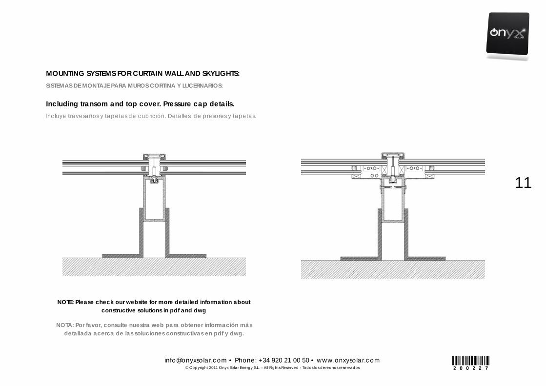
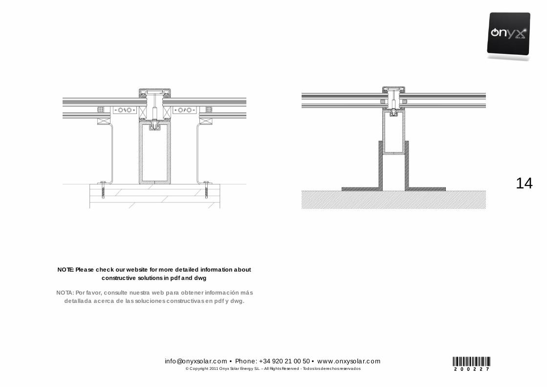
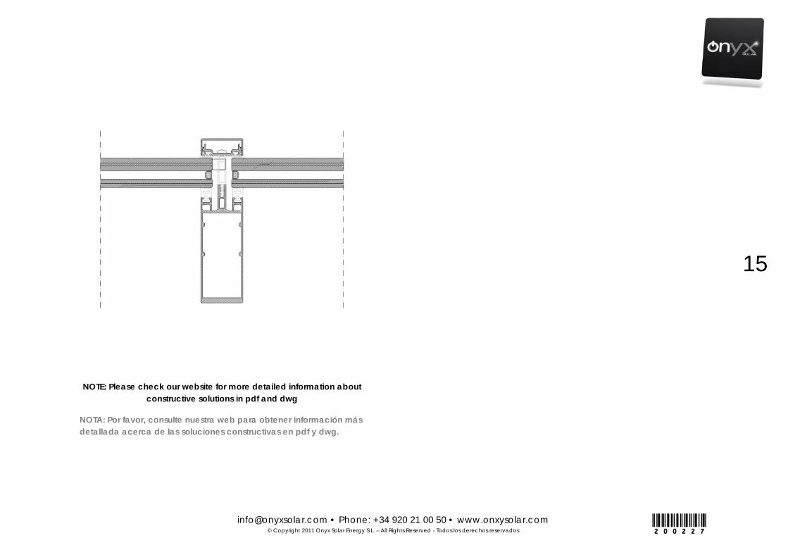
MOUNTING SYSTEMS FOR CURTAIN WALL AND SKYLIGHTS: SISTEMAS DE MONTAJE PARA MUROS CORTINA Y LUCERNARIOS:
Including transom and top cover. Pressure cap details. Incluye travesaños y tapetas de cubrición. Detalles de presores y tapetas.
NOTE: Please check our website for more detailed information about constructive solutions in pdf and dwg
NOTA: Por favor, consulte nuestra web para obtener información más detallada acerca de las soluciones constructivas en pdf y dwg.
[email protected] • Phone: +34 920 21 00 50 • www.onxysolar.com © Copyright 2011 Onyx Solar Energy S.L. – All Rights Reserved - Todos los derechos reservados
12
200227
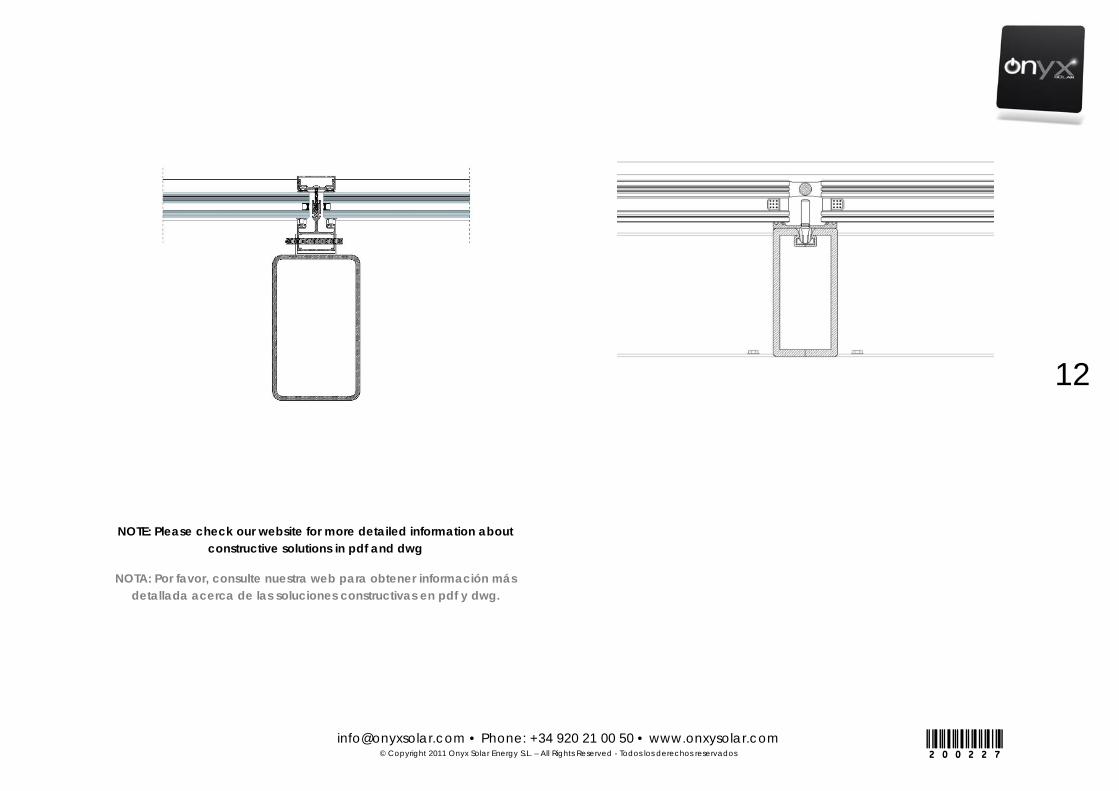
NOTE: Please check our website for more detailed information about constructive solutions in pdf and dwg
NOTA: Por favor, consulte nuestra web para obtener información más detallada acerca de las soluciones constructivas en pdf y dwg.

[email protected] • Phone: +34 920 21 00 50 • www.onxysolar.com © Copyright 2011 Onyx Solar Energy S.L. – All Rights Reserved - Todos los derechos reservados
13
200227
NOTE: Please check our website for more detailed information about constructive solutions in pdf and dwg
NOTA: Por favor, consulte nuestra web para obtener información más detallada acerca de las soluciones constructivas en pdf y dwg.
[email protected] • Phone: +34 920 21 00 50 • www.onxysolar.com © Copyright 2011 Onyx Solar Energy S.L. – All Rights Reserved - Todos los derechos reservados
14
200227
NOTE: Please check our website for more detailed information about constructive solutions in pdf and dwg
NOTA: Por favor, consulte nuestra web para obtener información más detallada acerca de las soluciones constructivas en pdf y dwg.
[email protected] • Phone: +34 920 21 00 50 • www.onxysolar.com © Copyright 2011 Onyx Solar Energy S.L. – All Rights Reserved - Todos los derechos reservados
15
200227
NOTE: Please check our website for more detailed information about constructive solutions in pdf and dwg
NOTA: Por favor, consulte nuestra web para obtener información más detallada acerca de las soluciones constructivas en pdf y dwg.
[email protected] • Phone: +34 920 21 00 50 • www.onxysolar.com © Copyright 2011 Onyx Solar Energy S.L. – All Rights Reserved - Todos los derechos reservados
16
200227
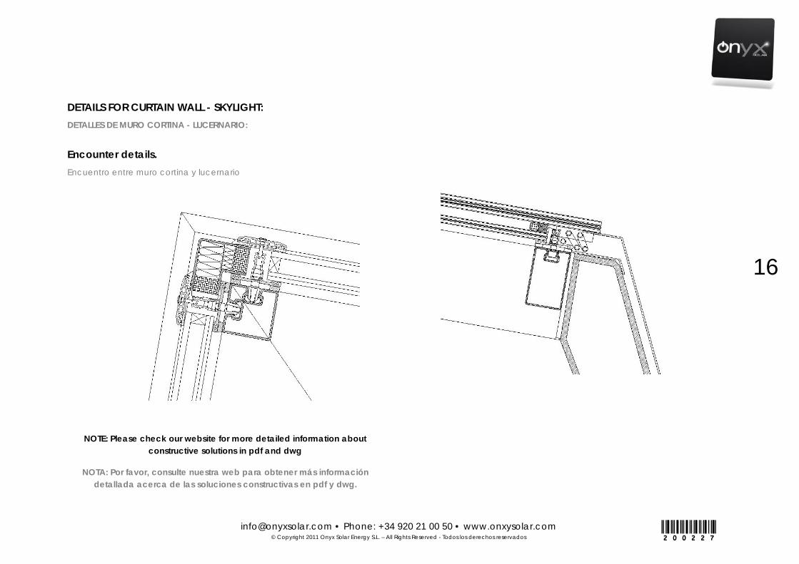
DETAILS FOR CURTAIN WALL - SKYLIGHT: DETALLES DE MURO CORTINA - LUCERNARIO:
Encounter details. Encuentro entre muro cortina y lucernario
NOTE: Please check our website for more detailed information about constructive solutions in pdf and dwg
NOTA: Por favor, consulte nuestra web para obtener más información detallada acerca de las soluciones constructivas en pdf y dwg.

[email protected] • Phone: +34 920 21 00 50 • www.onxysolar.com © Copyright 2011 Onyx Solar Energy S.L. – All Rights Reserved - Todos los derechos reservados
17
200227
STRUCTURAL SYSTEM FOR OPERABLE SKYLIGHTS: SISTEMA ESTRUCTURAL PARA LUCERARIOS PRACTICABLES:
Details. Detalles.
NOTE: Please check our website for more detailed information about constructive solutions in pdf and dwg
NOTA: Por favor, consulte nuestra web para obtener información más detallada acerca de las soluciones constructivas en pdf y dwg.

[email protected] • Phone: +34 920 21 00 50 • www.onxysolar.com © Copyright 2011 Onyx Solar Energy S.L. – All Rights Reserved - Todos los derechos reservados
18
200227
SYSTEMS FOR ROOF TOP INSTALLATION: INSTALACIÓN DE SISTEMAS PARA CUBIERTAS:
Details. Detalles.
NOTE: Please check our website for more detailed information about constructive solutions in pdf and dwg
NOTA: Por favor, consulte nuestra web para obtener información más detallada acerca de las soluciones constructivas en pdf y dwg.
MOUNTING SYSTEMS FOR PV WALKABLE FLOOR: SISTEMAS DE MONTAJE PARA SUELO PV TRANSITABLE:
Details. Detalles.
[email protected] • Phone: +34 920 21 00 50 • www.onxysolar.com © Copyright 2011 Onyx Solar Energy S.L. – All Rights Reserved - Todos los derechos reservados
19
200227
ELECTRICAL INSTALLATION OF PV GLASS
Modules are classified at the production line depending on their
power. They are already prepared to be connected in series or in
parallel.
Series or parallel assembly?
This will depend on the voltage required. If a high voltage is
required we will connect the modules in series because final
voltage will be V= V1+V2+…….Vn and the intensity value
I=I1=I2……..=In
If on the other hand we are interested in obtaining high current
intensities we will go for a connection in parallel: I=I1+I2……..In.
V= V1=V2=…….=Vn.
The maximum recommended configuration for modules
connected in series is 1000V voltage (600V for USA). Isolation is
guaranteed up to this voltage.
In a parallel connection you can connect as many modules as
the gadget to which it is connected admits (i.e: inverter,
combiner box, regulator or other suitable equipment).
Always use suitable cables: high voltages or currents can
produce short-circuit and degrade them by overheating. Please
follow local/national electrical codes.
INSTALACIÓN ELÉCTRICA DE UNIDADES DE VIDRIO FOTOVOLTAICO
Los submódulos se clasifican en la línea de producción en función
de su potencia. Estos ya están preparados para ser conectados en
serie o en paralelo.
¿Montaje en Serie o montaje en paralelo?
Esto dependerá de la tensión necesaria. Si se requiere un alto
voltaje se conectará los módulos en serie porque el voltaje final
será V=V1+V2+.......Vn y el valor de intensidad I=I1=I2=........In
Si por el contrario estamos interesados en el incremento de
intensidad de corriente vamos a realizar una conexión en
paralelo: I = I1 + I2........ In. En donde la tensión se mantiene
constante V = V1 = V2 =....... = Vn.
La configuración máxima recomendada para los módulos
conectados en serie es de 1000V (600 V para EE.UU.). El
aislamiento está garantizado hasta este voltaje.
En una conexión en paralelo se pueden conectar tantos
módulos como esta conexión admita (por ejemplo: inversor,
caja de protección, regulador u otro equipo adecuado).
Utilizar siempre cables adecuados: las altas tensiones o
corrientes pueden producir cortocircuitos y degradarlos por
sobrecalentamiento. Por favor, siga la normativa eléctrica
nacional y local.

[email protected] • Phone: +34 920 21 00 50 • www.onxysolar.com © Copyright 2011 Onyx Solar Energy S.L. – All Rights Reserved - Todos los derechos reservados
20
200227
Please read carefully the manual of all additional equipments
needed in a PV system such as inverters, regulator, batteries…
Recommendations of the manufacturers must be followed.
Protections: For certain BOS and applications (especially BOS for
thin film technology) it would be necessary the integration of
short-circuit current limiting fuses per a given number of strings to
increase electrical safety and optimized maintenance.
BIPV units must be connected and interconnected by an electrical
installer with proven experience in PV installations and low-voltage
systems. The PV installation design must be certified by a registered
professional electrical engineer. The PV BOS design and installation
procedure must comply with local codes and requirements from all
relevant authorities.
PV systems, as any electrical devices, require good ventilation ensuring
proper thermal dispersion. Any solution preventing the aforementioned
as: as silicone sealed of wiring, wrong cabling tubing de-ratio values,
unproper wiring tubing sections, etcs MUST be avoided.
Por favor, lea atentamente el manual de todos los equipos
adicionales necesarios en un sistema fotovoltaico, como
inversores, reguladores, baterías... Las recomendaciones de los
fabricantes deben ser seguidas.
Protecciones: Para ciertos balances de sistema y aplicaciones
(especialmente balances hechos para la tecnología de capa
fina), será necesaria la integración de un límite para el
cortocircuito a través de la caja de protección con su
correspondiente fusible de protección. Se pueden colocar más
elementos de corte para ganar en flexibilidad en la instalación.
Las conexiones e interconexiones entre las unidades BIPV deberán ser
realizadas por un instalador eléctrico autorizado con la experiencia
adecuada y comprobada en instalaciones fotovoltaicas y sistemas de
bajo voltaje. El diseño de la instalación PV debe ser certificado por un
ingeniero cualificado. En el proceso de diseño de la instalación y en la
ejecución de la instalación fotovoltaica se debe tener en cuenta el
cumplimiento de la normativa local exigible correspondiente y cumplir
con todos los requisitos de las autoridades pertinentes.
Los sistemas fotovoltaicos, así como cualquier componente eléctrico,
requieren buena ventilación para garantizar la adecuada dispersión
térmica. Se debe evitar cualquier solución como: el sellado del
cableado o componentes eléctricos con silicona, mala relación entre
el cableado y su canalización, cableado no adecuado,
canalizaciones no adecuadas, etc.
[email protected] • Phone: +34 920 21 00 50 • www.onxysolar.com © Copyright 2011 Onyx Solar Energy S.L. – All Rights Reserved - Todos los derechos reservados
21
200227
There is risk of fall while installing the modules on the structure,
for these reason workers must wear the necessary security systems such
as harness, gloves or adequate footwear.
To avoid any type of risk while assembling the system, whether
isolated or for grid connection, all elements, including structure, must
be earth connected. It is installer’s responsibility to find the most suitable
earth system based in washers/screws system, clamps, etc. Any
galvanization effect should be avoided.
For thin film projects the Balance of System should be carried out taken into
account the following points:
1. Negative grounding should be carried out.
2. It is desired to use inverters with transformers
3. If it is not possible to use inverters with transformers, then the possibility of
installing transformers separately should be considered.
If (2) and (3) is not possible, then negative grounding becomes more critical
and shall be faced.
Existe riesgo de caída durante la instalación de los módulos
sobre la estructura, los trabajadores deben usar los sistemas de
seguridad necesarios, tales como arneses, guantes y calzado
adecuado.
Para evitar cualquier tipo de riesgo, durante el montaje del
sistema, ya sea aislado o de conexión a la red, todos los elementos,
incluyendo la estructura, deben estar conectados a tierra. Es
responsabilidad del instalador encontrar el sistema de tierra más
adecuado, basado en el sistema de arandela/tornillo, abrazaderas,
etc. Debe evitarse la aparición de corrosión.
Para proyectos con tecnología de silicio amorfo la instalación de
conexionado se debe realizar teniendo en cuenta los siguientes puntos:
1. Se debe realizar conexión del conductor negativo a tierra
2. Se deben utilizar inversores eléctricos con transformador
3. Si no es posible utilizar inversores con los transformadores, debe
considerarse la posibilidad de instalar transformadores externos.
Si (2) y (3) no son posibles, se debe asumir una situación más crítica y una
instalación no optimizada.

[email protected] • Phone: +34 920 21 00 50 • www.onxysolar.com © Copyright 2011 Onyx Solar Energy S.L. – All Rights Reserved - Todos los derechos reservados
22
200227
JUNCTION BOX, WIRING AND CONNECTORS:
Junction Box:
Onyx Solar PV glasses are designed allowing different Junction Box (JB)
implementation depending on each product type, standard or customized.
JB can be placed at any point in the rear glass, can be welding or no-
potting compatible, and can hold a variable number of by-pass diodes.
In the case of edge junction boxes, the Junction Boxes are designed to be
run within a structure as aluminum/steel frames allowing both, good
ventilation and absence of moisture. Direct exposure to external outdoors
conditions should be avoided.
As general characteristics it should be pointed out that any JB system used
by Onyx shows IP-65 protection grade
Onyx Solar usually produces BIPV units using the following junction boxes:
CAJA DE CONEXIONES (JB), CABLEADO Y CONECTORES:
Caja de conexiones:
Las unidades de vidrio fotovoltaico Onyx Solar están diseñadas para
fabricarse con diferentes tipos de cajas de conexiones (JB), y su aplicación
será en función de cada tipo de producto, estándar o personalizado. Las
JB se pueden colocar en cualquier punto en el vidrio trasero, se pueden
soldar, y pueden contener un número variable de diodos de by-pass.
En el caso de cajas de conexiones laterales, éstas están diseñadas para
colocarse dentro de una perfilería estructural de aluminio o acero, y se
deberá garantizar tanto la ventilación como la ausencia de humedad.
Debe evitarse la exposición directa a condiciones ambientales del exterior.
Como características generales, cabe señalar que cualquier caja de
conexiones utilizada por Onyx garantizará un grado de protección IP- 65.
Onyx Solar fabrica las unidades de vidrio BIPV usando los siguientes
modelos de cajas de conexiones:
[email protected] • Phone: +34 920 21 00 50 • www.onxysolar.com © Copyright 2011 Onyx Solar Energy S.L. – All Rights Reserved - Todos los derechos reservados
23
200227
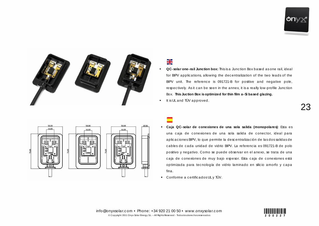
QC-solar one-rail Junction box: This is a Junction Box based as one rail, ideal
for BIPV applications, allowing the decentralization of the two leads of the
BIPV unit. The reference is 091721-B for positive and negative pole,
respectively. As it can be seen in the annex, it is a really low-profile Junction
Box. This Juction Box is optimized for thin film a-Si based glazing.
It is UL and TÜV approved.
Caja QC-solar de conexiones de una sola salida (monopolares): Esta es
una caja de conexiones de una sola salida de conector, ideal para
aplicaciones BIPV, lo que permite la descentralización de las dos salidas de
cables de cada unidad de vidrio BIPV. La referencia es 091721-B de polo
positivo y negativo. Como se puede observar en el anexo, se trata de una
caja de conexiones de muy bajo espesor. Esta caja de conexiones está
optimizada para tecnología de vidrio laminado en silicio amorfo y capa
fina.
Conforme a certificados UL y TÜV.

[email protected] • Phone: +34 920 21 00 50 • www.onxysolar.com © Copyright 2011 Onyx Solar Energy S.L. – All Rights Reserved - Todos los derechos reservados
24
200227
Note: Further information including technical specifications can be found in
ANNEX I
Multi-contact: This Junction Box is selected for crystalline applications
counting on two dipoles and 3 diodes for cell string protection and
allowing 4 ribbon entries. These characteristics allow high power and
large photocurrents as typically found in crystalline technology. It is
compatible with MC4/LC4 connectors and it is UL and TÜV approved.
The product reference is: PV-JBMF-U02.
Multi-Contact: Esta caja de conexiones se selecciona para
aplicaciones de tecnología de silicio cristalino contando con dos
dipolos y permite la conexión mediante 3 diodos para la protección de
las series de células. Estas características permiten más potencia e
intensidades más elevadas, como se encuentran típicamente en la
tecnología cristalina. Es compatible con conectores MC4/LC4 y es UL y
TÜV. La referencia del producto es: PV- JBMF -U02.
Nota: Se puede encontrar más información en las especificaciones
técnicas incluidas en el ANEXO I

[email protected] • Phone: +34 920 21 00 50 • www.onxysolar.com © Copyright 2011 Onyx Solar Energy S.L. – All Rights Reserved - Todos los derechos reservados
25
200227
Wiring:
Onyx Solar uses wiring classified as solar wiring with variable length, and
sections from 2,5 to 4mm2 (AWG 14, 12). These sections allow:
Nominal Current: 42 A
Nominal Voltage: 600/ 1000 VAC 1800 VDC
Max Acceptable Operating Temperature: from -40 to 85 ºC
Connectors:
Photovoltaic field attachable connectors, with crimp contact.
Use specific connectors for photovoltaic panels
Never disconnect nor connect while the circuit is loaded
Disconnected connectors should be protected from filth and water
Note: connectors are usually LC4, MC4, MC4 compatible or Tyco.
Cableado:
Onyx Solar utiliza el cableado clasificado como cableado solar con
longitud variable, las secciones son de 2,5 a 4mm2 (AWG 14, 12). Estas
secciones permiten:
Corriente nominal: 42 A
Voltaje nominal: 600/1000 VCA 1800 VDC
Max temperatura aceptable de funcionamiento: -40 a 85ºC
Conectores:
Conectores acoplables al campo fotovoltaico, con contactos de
crimpado.
Utilice conectores específicos para los paneles fotovoltaicos.
Nunca desconecte ni conecte mientras el circuito está en carga.
Los conectores desconectados deben estar protegidos de la
suciedad y el agua.
Nota: Los conectores son generalmente LC4, MC4, MC4 compatible o Tyco.

[email protected] • Phone: +34 920 21 00 50 • www.onxysolar.com © Copyright 2011 Onyx Solar Energy S.L. – All Rights Reserved - Todos los derechos reservados
26
200227
General Notes:
To avoid any type of risk while assembling the system, whether
isolated or for grid connection, firstly the panel or the structure must be earth
connected.
Once all the modules have been placed they will be inter
connected.
Connection is really simple due to its extensions of quick plugging.
Junction boxes are fixed while manufacturing; they must be
protected from mechanical stress to keep inside connections in good
conditions. We must also keep the sealing intact.
Disposition of the connections allows to modify panel exit voltages,
this part will only be altered by the installer if previously authorized by
the supplying company, becoming ONYX SOLAR free of any
responsibility if this is not done.
Never change the protection diodes without previous authorization
from the JB manufacturer.
NOTE: Please kindly see the ANNEX JUCTION BOX/WIRING of this manual for
further details. There, specifications of different JBs and connectors used by
Onyx solar are provided. Further information can be provided upon request.
Notas generales:
Para evitar cualquier tipo de riesgo, durante el montaje del sistema,
ya sea aislado o de conexión a red, la estructura debe estar conectada a
tierra.
Una vez que todos los módulos se han colocado serán interconectados.
La conexión es muy sencilla gracias a sus extensiones de conexión
rápida.
Las cajas de conexiones se fijan en el proceso de fabricación, deben
estar protegidas de tensiones mecánicas para mantener las
interconexiones en buenas condiciones. También se debe mantener el
sellado intacto.
La disposición de las conexiones permite modificar los voltajes de salida
de los paneles, esta parte sólo se ve alterada por el instalador si es
autorizado previamente por la empresa suministradora, quedando Onyx
Solar libre de cualquier responsabilidad en caso de no hacerlo.
Nunca cambie los diodos de protección sin la previa autorización del
fabricante de cajas de conexión.
NOTA: Por favor, vea el ANEXO CAJA DE CONEXIONES/CABLEADO de este
manual para más detalles. Allí, se proporcionan especificaciones de
diferentes cajas de conexión y conectores utilizados por Onyx Solar. Se
puede proporcionar más información por petición del cliente.
[email protected] • Phone: +34 920 21 00 50 • www.onxysolar.com © Copyright 2011 Onyx Solar Energy S.L. – All Rights Reserved - Todos los derechos reservados
27
200227
2. HANDLING AND PACKAGING
MANIPULACIÓN Y EMBALAJE

[email protected] • Phone: +34 920 21 00 50 • www.onxysolar.com © Copyright 2011 Onyx Solar Energy S.L. – All Rights Reserved - Todos los derechos reservados
28
200227
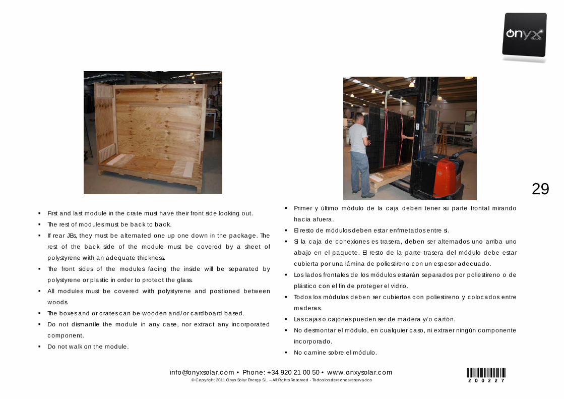
The BIPV units are usually not packaged
as conventional PV modules. Special
care should be taken when dealing with
glazing lites. In this sense, from our
experience we have designed safety
wood crates, where we take into
account the fragile nature of glazing,
weight and thickness. Depending on
dimensions, the wood crate
accommodates 6-34 BIPV units each and it is designed to resist loads from
glazing weight, torsion, or vibration.
The crates are based on maritime wood and imbedded in anti-cracking /
anti-crashing polymeric material. Desiccants are placed inside the unit load
to absorb any moisture.
Within the crate, the BIPV units are packed in vertical position for an
optimal distribution. First and last BIPV units are positioned face towards the
exterior being the rest organized back to back with alternating junction box
position. The BIPV modules are covered with polystyrene sheets using the
right thickness to protect the glazing against cracking or scratching.
Please see the diagram and pictures for better understanding.
You must pay special attention to the packaging, storage and
posterior transportation, well tying the modules up because the glass could
fracture and it would become useless. To avoid any torsion, modules must
be packaged in vertical position.
Las unidades BIPV normalmente no son
empaquetadas como los módulos fotovoltaicos
convencionales. Se debe tener especial cuidado
al tratarse de un material muy frágil como es el
vidrio o acristalamientos. En este sentido, a partir
de nuestra experiencia hemos diseñado cajas de
madera de seguridad teniendo en cuenta la
fragilidad del vidrio, el peso y el grosor.
Dependiendo de las dimensiones, la caja de
madera de 6-34 unidades BIPV cada una, está diseñado para resistir cargas
de acristalamiento peso, de torsión, o vibración.
Las cajas se basan en madera marítima y las unidades son embebidas en
un material polimérico anti-cracking/anti-rotura. Se introducen desecantes
dentro de cada caja para evitar la acumulación de humedad.
Dentro de la caja, las unidades BIPV se embalan en posición vertical para
una distribución óptima. La primera y última unidad BIPV se colocan cara
hacia el exterior; siendo el resto organizado en función de la posición de la
caja de conexiones alterna. Los módulos BIPV están cubiertos con láminas
de poliestireno utilizando el espesor adecuado para proteger el vidrio
contra grietas o arañazos.
Por favor, vea el diagrama y las fotos para una mejor comprensión.
Debe prestarse especial atención al transporte del embalaje,
almacenamiento; y tras la apertura, a la fijación de los módulos, dado que
el vidrio podría romperse. Para evitar cualquier tipo de torsión, los módulos
deben ser empaquetados en posición vertical.
[email protected] • Phone: +34 920 21 00 50 • www.onxysolar.com © Copyright 2011 Onyx Solar Energy S.L. – All Rights Reserved - Todos los derechos reservados
29
200227
First and last module in the crate must have their front side looking out.
The rest of modules must be back to back.
If rear JBs, they must be alternated one up one down in the package. The
rest of the back side of the module must be covered by a sheet of
polystyrene with an adequate thickness.
The front sides of the modules facing the inside will be separated by
polystyrene or plastic in order to protect the glass.
All modules must be covered with polystyrene and positioned between
woods.
The boxes and or crates can be wooden and/or cardboard based.
Do not dismantle the module in any case, nor extract any incorporated
component.
Do not walk on the module.
Primer y último módulo de la caja deben tener su parte frontal mirando
hacia afuera.
El resto de módulos deben estar enfrnetados entre si.
Si la caja de conexiones es trasera, deben ser alternados uno arriba uno
abajo en el paquete. El resto de la parte trasera del módulo debe estar
cubierta por una lámina de poliestireno con un espesor adecuado.
Los lados frontales de los módulos estarán separados por poliestireno o de
plástico con el fin de proteger el vidrio.
Todos los módulos deben ser cubiertos con poliestireno y colocados entre
maderas.
Las cajas o cajones pueden ser de madera y/o cartón.
No desmontar el módulo, en cualquier caso, ni extraer ningún componente
incorporado.
No camine sobre el módulo.
[email protected] • Phone: +34 920 21 00 50 • www.onxysolar.com © Copyright 2011 Onyx Solar Energy S.L. – All Rights Reserved - Todos los derechos reservados
30
200227
The panel is a physical body that supports certain voltage, distortion,
torsion…regulated by the competent norms but during installation and
without acknowledge of these norms it is recommendable to take certain
precautions. The panel must be transported being held from the longest
sides to avoid non desirable torsion effects.
Never bang the panel on any of its sides, specially the angles.
NOTE: Onyx designs different packaging and crating depending on specific
BIPV solution. Onyx reserves the right to change packaging design without
previous notice.
On-site Storage: Onyx Solar Photovoltaic Glass is a laminated glass product,
and as such, special attention shall be paid in regards to storage conditions:
the product shall be stored inside its original package/crate until installation
at the jobsite; crates should always be kept and stand on dry-soil areas, and
the glass should always be protected as needed to prevent damage to
glass and glazing materials from condensation, temperature changes or
other causes, especially after removed from its original package.
El panel es un cuerpo físico que soporta un determinado voltaje, una
resistencia a la deformación y torsión. Se debe tener conocimiento de los
límites según la norma. El panel debe ser transportado retenido a partir de
los lados más largos para evitar los efectos de torsión no deseables.
Nunca golpee el vidrio en cualquiera de sus lados, especialmente los
ángulos.
NOTA: los diferentes diseños de embalajes de Onyx dependen de la
solución específica BIPV. Onyx se reserva el derecho de cambiar el diseño
de embalajes sin previo aviso.
Almacenaje en obra: El vidrio fotovoltaico de Onyx Solar es un producto de
vidrio laminado y como tal, se debe tener especial atención con respecto
a las condiciones de almacenaje: el producto debe almacenarse dentro
de su embalaje/cajón hasta la instalación en obra; los cajones siempre
deben mantenerse almacenados en lugares secos y el vidrio siempre
deberá protegerse de posibles daños ocasionados por la condensación,
cambios bruscos de temperatura o de otras causas, especialmente
después de haberse extraido de su embalaje original.

[email protected] • Phone: +34 920 21 00 50 • www.onxysolar.com © Copyright 2011 Onyx Solar Energy S.L. – All Rights Reserved - Todos los derechos reservados
31
200227
lenght width heigth1245x300 mm 49"x11 13/16" 0,37 3.2+3.2 mm 6,54 34 222 264 0,398 1300 510 600
3.2+3.2 mm 12,60 34 428 483 0,597 1300 510 900 +Spacer 6 mm/4+4 27,00 28 756 836 1,055 1300 902 900 +Spacer 12 mm/4+4 27,00 28 756 847 1,252 1300 1070 900 +Spacer 16 mm/4+4 27,00 26 702 797 1,327 1300 1134 900 +Spacer 20 mm/4+4 27,00 26 702 803 1,448 1300 1238 900 +Double Spacer 12 mm/4/4+4 34,20 23 787 894 1,565 1300 1338 900
3.2+3.2 mm 13,84 34 470 525 0,597 1300 510 900 +Spacer 6 mm/4+4 29,65 28 830 910 1,055 1300 902 900 +Spacer 12 mm/4+4 29,65 28 830 921 1,252 1300 1070 900 +Spacer 16 mm/4+4 29,65 26 771 865 1,327 1300 1134 900 +Spacer 20 mm/4+4 29,65 26 771 872 1,448 1300 1238 900 +Double Spacer 12 mm/4/4+4 37,55 22 826 932 1,523 1300 1302 9003.2+5T mm 17,00 34 578 635 0,636 1300 544 900 +Spacer 6 mm/4+4 32,81 27 886 967 1,079 1300 922 900 +Spacer 12 mm/4+4 32,81 27 886 977 1,268 1300 1084 900 +Spacer 16 mm/4+4 32,81 26 853 950 1,367 1300 1168 900 +Spacer 20 mm/4+4 32,81 26 853 956 1,488 1300 1272 900 +Double Spacer 12 mm/4/4+4 40,71 21 855 960 1,521 1300 1300 9006T+3.2+6T mm 61,85 14 866 940 0,819 1300 420 1500 +Spacer 6 mm/4+4 92,78 9 835 938 1,536 1300 788 1500 +Spacer 12 mm/4+4 92,78 9 835 950 1,843 1300 945 1500 +Spacer 16 mm/4+4 92,78 9 835 958 2,048 1300 1050 1500 +Spacer 20 mm/4+4 92,78 9 835 967 2,252 1300 1155 1500 +Double Spacer 12 mm/4/4+4 108,24 7 758 906 2,662 1300 1365 1500
6T+3.2+6T mm 62,53 14 875 965 0,964 2550 420 900 +Spacer 6 mm/4+4 93,80 9 844 973 1,807 2550 788 900 +Spacer 12 mm/4+4 93,80 9 844 991 2,169 2550 945 900 +Spacer 16 mm/4+4 93,80 8 750 908 2,410 2550 1050 900 +Spacer 20 mm/4+4 93,80 8 750 920 2,651 2550 1155 900 +Double Spacer 12 mm/4/4+4 109,44 7 766 958 3,133 2550 1365 900
6T+3.2+6T mm 92,08 9 829 915 0,770 1900 270 1500 +Spacer 6 mm/4+4 138,12 6 829 939 1,443 1900 506 1500 +Spacer 12 mm/4+4 138,12 6 829 949 1,731 1900 608 1500 +Spacer 16 mm/4+4 138,12 6 829 956 1,924 1900 675 1500 +Spacer 20 mm/4+4 138,12 6 829 963 2,116 1900 743 1500 +Double Spacer 12 mm/4/4+4 161,14 5 806 953 2,501 1900 878 1500
6T+3.2+6T mm 122,31 7 856 962 0,803 2550 210 1500 +Spacer 6 mm/4+4 183,46 4 734 863 1,506 2550 394 1500 +Spacer 12 mm/4+4 183,46 4 734 872 1,807 2550 473 1500 +Spacer 16 mm/4+4 183,46 4 734 879 2,008 2550 525 1500 +Spacer 20 mm/4+4 183,46 4 734 885 2,209 2550 578 1500 +Double Spacer 12 mm/4/4+4 214,04 3 642 807 2,611 2550 683 1500
1641x989 mm 64 5/8" x 39"
1,62 4T+tedlar/PYE 23,50 24 564 715 2,652 1700 1200 1300
4T+4T mm 32,46 24 779 930 2,652 1700 1200 13005T+5T mm 40,57 20 811 963 2,652 1700 1200 13006T+6T mm 48,69 17 828 979 2,652 1700 1200 13008T+8T mm 64,92 12 779 930 2,652 1700 1200 13004T+tedlar/PYE 14,16 24 340 447 1,440 1600 1200 7504T+4T mm 11,75 24 282 389 1,440 1600 1200 750
600x600 mm 23 5/8"x23 5/8"
0,36 6T+3.2+6T mm 14,40 34 490 544 0,597 1300 510 900
LOG
ISTIC
INFO
RMA
TION
GLASS SIZE SQM CONFIGURATION PIECES/BOX (UNITS)
WEIGHT WITH PALLET BOX (KG)
VOLUME OF PALLET BOX (M3)
1200x600 mm 47 1/4"x23 5/8"
2,30
1,56
1,55
0,72
1245x1242 mm 49"x49"
2462x635 mm 97"x25"
1245x1849 mm 49"x73"
DIMENSIONS OF PALLET BOX (mm)
1245x2456 mm 49"x96 3/4"
WEIGHT/PIECE (KG)
WEIGHT WITHOUT PALLET BOX (KG)
1245x635 mm 49"x25"
0,79
3,06
The information given is only indicative and can be changed at any time without notice.
1,401650x850 mm 65" x 33 1/2"
1475x480 mm 58" x 18 7/8"
0,71
Logistic Information for standard photovoltaic glass:
Información Logística de vidrios fotovoltaicos estándar:
[email protected] • Phone: +34 920 21 00 50 • www.onxysolar.com © Copyright 2011 Onyx Solar Energy S.L. – All Rights Reserved - Todos los derechos reservados
32
200227
3. PREVENTIVE MAINTENANCE AND
CLEANING MANTENIMIENTO PREVENTIVO Y LIMPIEZA
[email protected] • Phone: +34 920 21 00 50 • www.onxysolar.com © Copyright 2011 Onyx Solar Energy S.L. – All Rights Reserved - Todos los derechos reservados
33
200227
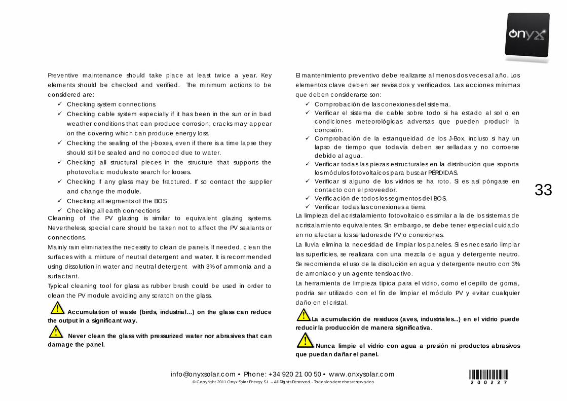
Preventive maintenance should take place at least twice a year. Key elements should be checked and verified. The minimum actions to be considered are: Checking system connections. Checking cable system especially if it has been in the sun or in bad
weather conditions that can produce corrosion; cracks may appear on the covering which can produce energy loss.
Checking the sealing of the j-boxes, even if there is a time lapse they should still be sealed and no corroded due to water.
Checking all structural pieces in the structure that supports the photovoltaic modules to search for looses.
Checking if any glass may be fractured. If so contact the supplier and change the module.
Checking all segments of the BOS. Checking all earth connections
Cleaning of the PV glazing is similar to equivalent glazing systems. Nevertheless, special care should be taken not to affect the PV sealants or connections. Mainly rain eliminates the necessity to clean de panels. If needed, clean the surfaces with a mixture of neutral detergent and water. It is recommended using dissolution in water and neutral detergent with 3% of ammonia and a surfactant. Typical cleaning tool for glass as rubber brush could be used in order to clean the PV module avoiding any scratch on the glass.
Accumulation of waste (birds, industrial…) on the glass can reduce the output in a significant way.
Never clean the glass with pressurized water nor abrasives that can damage the panel.
El mantenimiento preventivo debe realizarse al menos dos veces al año. Los elementos clave deben ser revisados y verificados. Las acciones mínimas que deben considerarse son: Comprobación de las conexiones del sistema. Verificar el sistema de cable sobre todo si ha estado al sol o en
condiciones meteorológicas adversas que pueden producir la corrosión.
Comprobación de la estanqueidad de los J-Box, incluso si hay un lapso de tiempo que todavía deben ser selladas y no corroerse debido al agua.
Verificar todas las piezas estructurales en la distribución que soporta los módulos fotovoltaicos para buscar PÉRDIDAS.
Verificar si alguno de los vidrios se ha roto. Si es así póngase en contacto con el proveedor.
Verificación de todos los segmentos del BOS. Verificar todas las conexiones a tierra
La limpieza del acristalamiento fotovoltaico es similar a la de los sistemas de acristalamiento equivalentes. Sin embargo, se debe tener especial cuidado en no afectar a los selladores de PV o conexiones. La lluvia elimina la necesidad de limpiar los paneles. Si es necesario limpiar las superficies, se realizara con una mezcla de agua y detergente neutro. Se recomienda el uso de la disolución en agua y detergente neutro con 3% de amoníaco y un agente tensioactivo. La herramienta de limpieza típica para el vidrio, como el cepillo de goma, podría ser utilizado con el fin de limpiar el módulo PV y evitar cualquier daño en el cristal.
La acumulación de residuos (aves, industriales...) en el vidrio puede reducir la producción de manera significativa.
Nunca limpie el vidrio con agua a presión ni productos abrasivos que puedan dañar el panel.
[email protected] • Phone: +34 920 21 00 50 • www.onxysolar.com © Copyright 2011 Onyx Solar Energy S.L. – All Rights Reserved - Todos los derechos reservados
34
200227
4. STANDARDS & CERTIFICATIONS
NORMATIVAS Y CERTIFICADOS
[email protected] • Phone: +34 920 21 00 50 • www.onxysolar.com © Copyright 2011 Onyx Solar Energy S.L. – All Rights Reserved - Todos los derechos reservados
35
200227
DEPENDING ON THE FINAL BIPV GLASS CONFIGURATION, IT CAN COMPLY WITH THE FOLLOWING STANDARDS:
Photovoltaic glass:
• IEC 61646: Thin-film terrestrial photovoltaic (PV) modules Design
qualification and type approval
• IEC 61215: Crystalline silicon terrestrial photovoltaic (PV) modules –
Design qualification and type approval
• IEC 61730-1: Safety qualification for PV modules of crystalline silicon
for construction use.
• UL 1703: Flat-Plate Photovoltaic Modules and Panels
• ISO 12543-4:2011. Glass in building - Laminated glass and laminated
safety glass
• EN 13501:2007. Fire classification of construction products and
building elements
• EN 356:2001. Resistance against hand stroke
• EN 410:2011. Glass in building - Determination of luminous and solar
characteristics of glazing.
• EN 12150:2005. Glass in building - Thermally toughened soda lime
silicate safety glass.
• EN 12600:2003. Glass in building - Pendulum test - Impact test
method and classification for flat glass
DEPENDIENDO DE LA CONFIGURACION FINAL, EL VIDRIO FV PUEDE CUMPLIR CON LAS SIGUIENTES NORMATIVAS:
Vidrio Fotovoltaico:
IEC 61646: Módulos fotovoltaicos (FV) de lámina delgada para uso
terrestre. Cualificación del diseño y homologación.
IEC 61215: Módulos fotovoltaicos (FV) de silicio cristalino para uso
terrestre. Cualificación del diseño y homologación.
IEC 61730-1: Cualificación de la seguridad de los módulos fotovoltaicos
(FV). Parte 1: Requisitos de construcción.
UL 1703: Módulos y Paneles Fotovoltaicos de Placa Plana.
ISO 12543-4:2011. Vidrio para la edificación. Vidrio laminado y vidrio
laminado de seguridad.
EN 13501:2007. Clasificación en función del comportamiento frente al
fuego de los productos de construcción y elementos para la
edificación.
EN 356:2001. Vidrio de construcción. Vidrio de seguridad. Ensayo y
clasificación de la resistencia al ataque manual.
EN 410:2011. Vidrio para la edificación. Determinación de las
características luminosas y solares de los acristalamientos.
EN 12150:2005. Vidrio para la edificación. Vidrio de silicato sodocálcico
de seguridad templado térmicamente.
EN 12600:2003. Vidrio para la edificación. Ensayo pendular. Método de
ensayo al impacto y clasificación para vidrio plano.

[email protected] • Phone: +34 920 21 00 50 • www.onxysolar.com © Copyright 2011 Onyx Solar Energy S.L. – All Rights Reserved - Todos los derechos reservados
36
200227
Interlayers:
ANSI Z97.1. Safety Glazing Materials Used in Buildings –
Safety Performance Specifications and Methods of Test.
ASTM D792. Standard Test Methods for Density and Specific
Gravity (Relative Density) of Plastics by Displacement.
ASTM E1269. Standard Test Method for Determining Specific
Heat Capacity by Differential Scanning Calorimetry.
ASTM D1004. Standard Test Method for Tear Resistance
(Graves Tear) of Plastic Film and Sheeting.
ASTM D542. Standard Test Method for Index of Refraction of
Transparent Organic Plastics.
ASTM E1354. Standard Test Method for Heat and Visible
Smoke Release Rates for Materials and Products Using an
Oxygen Consumption Calorimeter.
ASTM F433. Standard Practice for Evaluating Thermal
Conductivity of Gasket Materials.
ASTM D1929. Standard Test Method for Determining Ignition
Temperature of Plastics.
EN 410:2011. Glass in building - Determination of luminous
and solar characteristics of glazing.
JIS K6771. Flexible vinyl tube.
Encapsulantes:
ANSI Z97.1. Materiales de Vidrio de Seguridad usados en
Edificación - Especificaciones de Desempeño de
Seguridad y Métodos de Prueba.
ASTM D792. Métodos de Prueba Estándar para la Densidad
y Gravedad específica (Densidad Relativa) de plásticos
por Desplazamiento.
ASTM E1269. Método de Prueba Estándar para determinar
la capacidad calorífica específica mediante Análisis
Térmico Diferencial.
ASTM D1004. Método de Prueba Estándar para la
Resistencia al Desgarro de láminas de plástico.
ASTM D542. Método de Prueba Estándar para medir el
Índice de refracción de plásticos orgánicos transparentes.
ASTM E1354. Método de prueba estándar para el calor y
las tasas de emisiones visibles de humo Materiales y
Productos usando un calorímetro de consumo de oxígeno.
ASTM F433. Práctica estándar para la evaluación de la
conductividad térmica de los materiales de las juntas.
ASTM D1929. Método de prueba estándar para determinar
la temperatura de ignición de los plásticos.
EN 410:2011. Vidrio para la edificación. Determinación de
las características luminosas y solares de los
acristalamientos
JIS K6771. Tubo flexible de vinilo.

[email protected] • Phone: +34 920 21 00 50 • www.onxysolar.com © Copyright 2011 Onyx Solar Energy S.L. – All Rights Reserved - Todos los derechos reservados
37
200227
One Rail Junction Box:
UL approved.
TÜV approved to IEC 61215 ed. 2 approved.
Anti-Slip:
UNE ENV 12633:2003. Method of determination of
unpolished and polished slip/skid resistance value.
DIN 51130: Ramp Method Standard Footwear.
DIN 51097: Ramp Method Barefoot.
ASTM C 1028-07: Standard Test Method for Determining the
Static Coefficient of Friction of Ceramic Tile and Other Like-
Surfaces by the Horizontal Dynamometer Pull-Meter
Method.
Caja de conexiones Monopolar:
UL aprobada.
TÜV aprobada para IEC 61215 ed. 2 aprobada.
Anti-Deslizante:
UNE ENV 12633:2003. Método para la determinación del
valor de la resistencia al deslizamiento/resbalamiento de
los pavimentos pulidos y sin pulir.
DIN 51130: Método de rampa, Pies calzados.
DIN 51097: Método de rampa, Pies descalzos.
ASTM C 1028-07: Método de prueba estándar para
determinar el coeficiente de fricción estática de Baldosa
Cerámicas y Otras superficies similares por el método de
Dinamómetro Horizontal.

[email protected] • Phone: +34 920 21 00 50 • www.onxysolar.com © Copyright 2011 Onyx Solar Energy S.L. – All Rights Reserved - Todos los derechos reservados
38
200227
STANDARDS AND CERTIFICATIONS FOR PV FLOOR GLASS
ADA requirements of Slip coefficient *Slip resistance is based on the frictional
force needed on the walking surface to keep the shoes and crutches from
slipping while walking under otherwise slippery conditions. While the
dynamic coefficient of friction during walking varies in a complex and non-
uniform way, the static coefficient of friction, which can be measured in
several ways, provides a close approximation of the slip resistance of a
surface. The Occupational Safety and Health Administration recommend
that walking surfaces have a static coefficient of friction of 0.5. A research
project sponsored by the Architectural and Transportation Barriers
Compliance Board (Access Board) conducted tests with persons with
disabilities and concluded that a higher coefficient of friction was needed.
A static coefficient of friction of 0.6 is recommended for accessible routes
and 0.8 for ramps.
NORMATIVAS Y CERTIFICACIONES PARA EL SUELO FV
Requisitos de la ADA de Coeficiente de deslizamiento *La resistencia al
deslizamiento se basa en la fuerza de fricción necesaria para evitar que el
tacón de un zapato o la punta de una muleta se deslicen sobre una
superficie transitable bajo condiciones probables de encontrar en esa
superficie. Mientras que el coeficiente de fricción dinámico durante la
marcha varía de una forma compleja y no uniforme, el coeficiente estático
de fricción, que se puede medir de varias maneras, proporciona una
estrecha aproximación de la resistencia al deslizamiento de una superficie.
La Administración de Seguridad y Salud recomiendan que las superficies
transitables tengan un coeficiente de fricción estática de 0,5. Un proyecto
de investigación patrocinado por la Junta de Cumplimiento de Barreras
Arquitectónicas y de Transporte (Access Board) llevó a cabo pruebas con
personas con discapacidad y concluyó que un mayor coeficiente de
fricción era necesario para tales personas. Se recomienda un coeficiente
estático de fricción de 0,6 para rutas accesibles y 0,8 para las rampas.
DESCRIPTION
DESCRIPCIÓN
UNE ENV 12633 Pendulum method / Prueba pendular
DIN 51130 Ramp method Shod foot / Pie calzado en rampa
DIN 51097 Ramp method Bare foot / Pie descalzo en rampa
ASTM C 1028-07 Coefficient Dry / coeficiente seco
Coefficient Wet / coeficiente húmedo
EN 101:91 MOHS Surface hardness / dureza superficial
UL 410 Slip coefficient / coeficiente de deslizamiento
Scale 4
> 0,6
FLOOR GLASS CERTIFICATION
CERTIFICACIÓN DE SUELO
CLASIFICATION
CLASIFICACIÓNClass 3
R-12
Class B
≥ 0,7
≥ 0,6
[email protected] • Phone: +34 920 21 00 50 • www.onxysolar.com © Copyright 2011 Onyx Solar Energy S.L. – All Rights Reserved - Todos los derechos reservados
39
200227
Any type of manipulation or installation that is not contained in the
norms stipulated in this document, along with any other concerns, the
installer must be consulted with the supplier company to receive proper
instructions.
Cualquier tipo de manipulación o instalación que no esté contenida en
las normas estipuladas en este documento y que pueda significar alguna
duda para el instalador, debe ser consultado con la empresa proveedora
para recibir la información correspondiente.
[email protected] • Phone: +34 920 21 00 50 • www.onxysolar.com © Copyright 2011 Onyx Solar Energy S.L. – All Rights Reserved - Todos los derechos reservados
40
200227

[email protected] • Phone: +34 920 21 00 50 • www.onxysolar.com © Copyright 2011 Onyx Solar Energy S.L. – All Rights Reserved - Todos los derechos reservados
41
200227
[email protected] • Phone: +34 920 21 00 50 • www.onxysolar.com © Copyright 2011 Onyx Solar Energy S.L. – All Rights Reserved - Todos los derechos reservados
42
200227
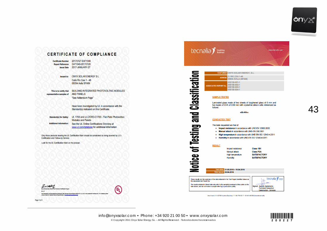
[email protected] • Phone: +34 920 21 00 50 • www.onxysolar.com © Copyright 2011 Onyx Solar Energy S.L. – All Rights Reserved - Todos los derechos reservados
43
200227
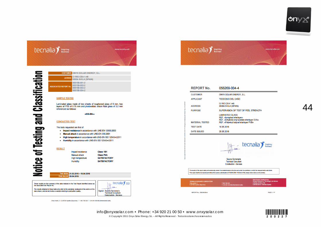
[email protected] • Phone: +34 920 21 00 50 • www.onxysolar.com © Copyright 2011 Onyx Solar Energy S.L. – All Rights Reserved - Todos los derechos reservados
44
200227

[email protected] • Phone: +34 920 21 00 50 • www.onxysolar.com © Copyright 2011 Onyx Solar Energy S.L. – All Rights Reserved - Todos los derechos reservados
45
200227
[email protected] • Phone: +34 920 21 00 50 • www.onxysolar.com © Copyright 2011 Onyx Solar Energy S.L. – All Rights Reserved - Todos los derechos reservados
46
200227
5. WARRANTY
CERTIFICADO DE GARANTÍA DEL PRODUCTO

[email protected] • Phone: +34 920 21 00 50 • www.onxysolar.com © Copyright 2011 Onyx Solar Energy S.L. – All Rights Reserved - Todos los derechos reservados
47
200227
Onyx Solar Energy S.L., a company dedicated to the development of BIPV solutions for buildings and other sustainable building solutions, guarantees the quality of the glass/glass modules according to the technical specifications and applicable regulations described in this submittal. Terms and conditions of the glass/glass PV Module warranty are expressed as follows:
1. WARRANTY DESCRIPTION
A) LIMITED WARRANTY FOR MATERIALS AND MANUFACTURING DEFECTS.
Onyx Solar Energy S.L guarantees during a period of 5 years, starting from the initial purchase date, that the PV Module is free from any defect in material or manufacture.
If, during the WARRANTY term, your PV Module became inoperative as a consequence of any defect in the manufacturing or the materials, Onyx Solar Energy S.L (after verifying the communicated defect) reserves the right to choose between repairing the defective module, substituting an equivalent one or refunding the price of the defective module.
Onyx Solar Energy S.L., empresa dedicada al desarrollo de soluciones de Integración Fotovoltaica para Edificios (BIPV, por sus siglas en inglés) y otras soluciones sostenibles para la construcción, garantiza la calidad de sus vidrios fotovoltaicos de acuerdo a las especificaciones técnicas y a las legislaciones pertinentes descritas en este manual. Los términos y condiciones de la garantía de los vidrios/módulos de vidrio fotovoltaicos se expresan a continuación:
1. DESCRIPCIÓN DE LA GARANTÍA
A) GARANTÍA PARA MATERIALES POR DEFECTOS DE MATERIALES Y FABRICACIÓN.
Onyx Solar Energy S.L garantiza que durante un periodo de 5 años desde la fecha de compra, el modulo fotovoltaico estará libre de defectos en sus materiales o fabricación.
Si, durante el periodo de validez de esta garantía, el modulo fotovoltaico adquirido resulta inoperativo como consecuencia de cualquier defecto en la fabricación o en los materiales, Onyx Solar Energy S.L (tras verificar el defecto comunicado) se reserva el derecho a elegir entre reparar el modulo defectuoso, substituirlo por uno equivalente o devolver el precio del módulo defectuoso.
[email protected] • Phone: +34 920 21 00 50 • www.onxysolar.com © Copyright 2011 Onyx Solar Energy S.L. – All Rights Reserved - Todos los derechos reservados
48
200227
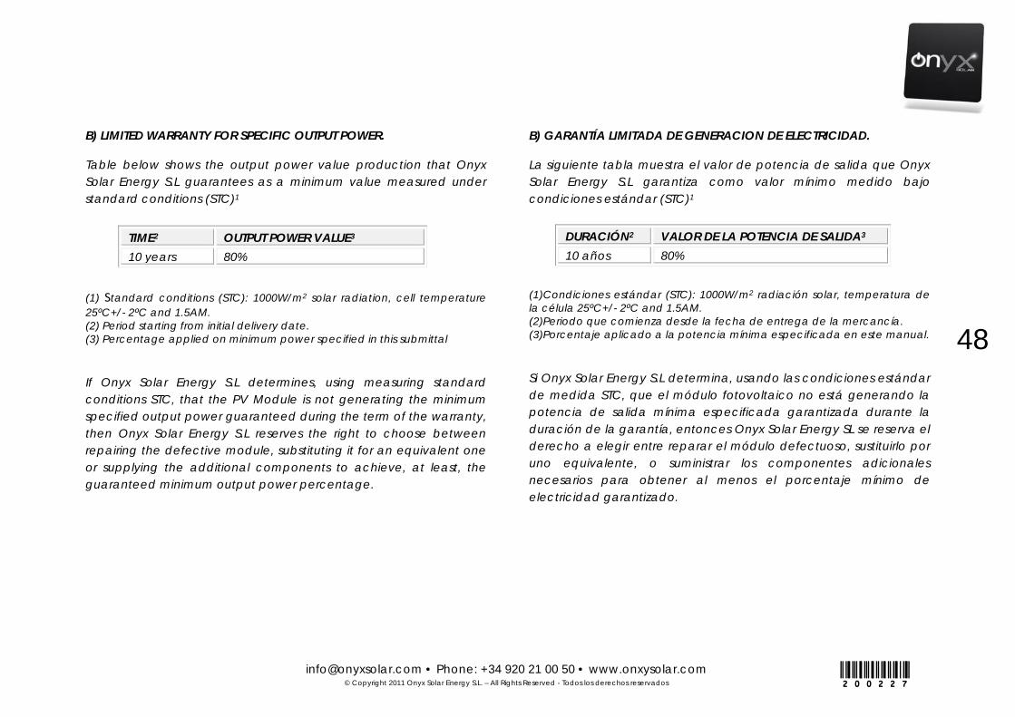
B) LIMITED WARRANTY FOR SPECIFIC OUTPUT POWER.
Table below shows the output power value production that Onyx Solar Energy S.L guarantees as a minimum value measured under standard conditions (STC)1
(1) Standard conditions (STC): 1000W/m2 solar radiation, cell temperature 25ºC+/- 2ºC and 1.5AM. (2) Period starting from initial delivery date. (3) Percentage applied on minimum power specified in this submittal
If Onyx Solar Energy S.L determines, using measuring standard conditions STC, that the PV Module is not generating the minimum specified output power guaranteed during the term of the warranty, then Onyx Solar Energy S.L reserves the right to choose between repairing the defective module, substituting it for an equivalent one or supplying the additional components to achieve, at least, the guaranteed minimum output power percentage.
B) GARANTÍA LIMITADA DE GENERACION DE ELECTRICIDAD.
La siguiente tabla muestra el valor de potencia de salida que Onyx Solar Energy S.L garantiza como valor mínimo medido bajo condiciones estándar (STC)1
(1)Condiciones estándar (STC): 1000W/m2 radiación solar, temperatura de la célula 25ºC+/- 2ºC and 1.5AM. (2)Periodo que comienza desde la fecha de entrega de la mercancía. (3)Porcentaje aplicado a la potencia mínima especificada en este manual.
Si Onyx Solar Energy S.L determina, usando las condiciones estándar de medida STC, que el módulo fotovoltaico no está generando la potencia de salida mínima especificada garantizada durante la duración de la garantía, entonces Onyx Solar Energy SL se reserva el derecho a elegir entre reparar el módulo defectuoso, sustituirlo por uno equivalente, o suministrar los componentes adicionales necesarios para obtener al menos el porcentaje mínimo de electricidad garantizado.
TIME2 OUTPUT POWER VALUE3
10 years 80% DURACIÓN2 VALOR DE LA POTENCIA DE SALIDA3
10 años 80%
[email protected] • Phone: +34 920 21 00 50 • www.onxysolar.com © Copyright 2011 Onyx Solar Energy S.L. – All Rights Reserved - Todos los derechos reservados
49
200227
2. GENERAL TERMS.
The following conditions will be applicable to the PV glass/glass modules provided by Onyx Solar Energy S.L for this project and guaranteed according to the section above.
Onyx Solar Energy S.L can, according to its own criteria, use new pieces or new products or refurbished products to repair the module or substitute the module under this WARRANTY with a new or refurbished one.
Onyx Solar Energy S.L reserves the right to supply a different but equivalent module to attend the accepted claims in the case that the manufacturing of the original module may have ceased or that the initial specifications have been modified.
Onyx Solar Energy S.L is not responsible for, and the client hereby accepts responsibility for the costs of any local work and any cost associated to the installation, elimination, reinstallation or transportation of the module and/or any other associate component serviced during the WARRANTY period.
The warranty offered herein will be applicable only while the (i) product is property of the initial purchaser that acquired the product for his own use and not in order to resell or (ii) acquired as a result of the purchase of the building where the product is installed.
The validity of the present warranty will not be extended beyond the original period specified and described in sections A) and B) of the present certificate.
2. TÉRMINOS GENERALES.
Las siguientes condiciones serán aplicables a los vidrios/módulos de vidrio fotovoltaicos suministrados por Onyx Solar Energy S.L para este proyecto y garantizados de acuerdo a la sección anterior.
Onyx Solar Energy S.L puede, a su elección, utilizar partes o productos nuevos o restaurados para reparar el panel o la sustitución del panel bajo GARANTÍA con uno restaurado o por uno nuevo.
Onyx Solar Energy S.L se reserva el derecho a suministrar un módulo equivalente diferente del suministrado inicialmente, para atender las reclamaciones de garantía en el caso de que haya cesado la fabricación del módulo original o las especificaciones iniciales hayan sido modificadas.
Onyx Solar Energy S.L no es responsable de, y el cliente acepta hacerse cargo de los costes de cualquier mano de obra local o cualquier coste asociado a la instalación, eliminación, reinstalación o transporte del módulo y/o cualquier otro componente asociado sujeto a servicio durante la garantía proporcionada.
La garantía aquí ofrecida será aplicable solo si el producto es (i) propiedad del comprador inicial que adquirió este producto para su uso propio y no para reventa o (ii) si fue adquirido como resultado de la compra de la propiedad inmobiliaria donde el producto fue instalado.
La validez de la presente garantía no se extenderá más allá del periodo original especificado y descrito en las secciones A) y B) del presente certificado.
[email protected] • Phone: +34 920 21 00 50 • www.onxysolar.com © Copyright 2011 Onyx Solar Energy S.L. – All Rights Reserved - Todos los derechos reservados
50
200227
3. EXCLUSIONS AND LIMITATION OF WARRANTY
The warranties herein offered do not cover damage, failure or defects caused by:
• Not following the installation, functioning or maintenance instructions offered by Onyx Solar Energy S.L
• Reparations, modifications or manipulation of the modules object of the present WARRANTY done by any other person that is not a technician authorized by Onyx Solar Energy S.L, or if the PV glass/glass modules are connected to non-recommended equipment.
• Misuse or negligent acts. • Damage caused by over tension, atmospheric discharge,
fire, floods, plague, acts of god, accidental breakage, actions by third parties and other events or accidents beyond reasonable control by Onyx Solar Energy S.L and those that do not occur under normal operating conditions.
• Breakage of the laminates if the modules are installed on systems not recommended by Onyx Solar Energy S.L.
PV modules with manipulated series number or non-recognizable identification shall not be subject to the WARRANTY.
Onyx Solar Energy S.L does NOT give any WARRANTY, explicit or implicit, different from the warranties herein expressed and is not guaranteeing nor responsible for suitability of the module for any purpose.
3. EXCLUSIONES Y LIMITACIONES DE LA GARANTÍA
Las garantías aquí ofrecidas no cubren el daño, fallo o defecto causado por:
• No seguir las instrucciones de instalación, funcionamiento o mantenimiento establecidas por Onyx Solar Energy S.L
• Reparaciones, modificaciones o manipulaciones de los módulos objeto de la presente GARANTÍA realizadas por cualquier persona que no sea un técnico autorizado por Onyx Solar Energy S.L, o si módulos de vidrio fotovoltaicos han sido conectados a equipos no recomendados.
• Mal uso o negligencia. • Daño causado por excesiva tensión, descarga atmosférica,
fuego, inundaciones, plagas, actos de fuerza mayor, daños accidentales, acción de terceras partes o cualquier otro suceso o accidente fuera del control razonable de Onyx Solar Energy S.L y aquellos que no ocurren bajo condiciones operativas normales.
• Daños de los laminados si los módulos están instalados en sistemas no recomendados por Onyx Solar Energy S.L..
Aquellos módulos fotovoltaicos con números de serie manipulados o sin identificación reconocible no estarán sujetos a esta GARANTÍA.
Onyx Solar Energy S.L NO concede ninguna GARANTÍA, explícita o implícita, diferente a las garantías aquí expresadas y no garantiza ni es en ningún caso responsable de la idoneidad o validez del módulo para ningún fin determinado.
[email protected] • Phone: +34 920 21 00 50 • www.onxysolar.com © Copyright 2011 Onyx Solar Energy S.L. – All Rights Reserved - Todos los derechos reservados
51
200227
4. CLAIM FOR THE SERVICE UNDER WARRANTY AND/OR INFORMATION ABOUT THE OPTIONS FOR DISPOSITION AND RECYCLING.
Onyx Solar Energy S.L is not responsible for any special, incidental, consequential or punitive damage that may result from the use or lack of use or failure of the module to perform the guaranteed function, including but not limited to damages for requested services, costs of substitution services, lost benefits or savings, and expenses resulting from lawsuit against third parties. The maximum responsibility of Onyx Solar Energy S.L under any WARRANTY, explicit or implicit or established by law or due to any manufacturing or design defect, is limited to the purchase price of the product. The buyer’s exclusive remedy for non-compliance of the WARRANTY or for manufacturing or design defect is only the one herein stated.
If at any time any controversy shall arise between BUYER and Onyx Solar Energy S.L regarding the warranties provided in this certificate, the parties hereto agree to attend mediation. In the event mediation is unsuccessful, both parties agree to submit any dispute to binding arbitration, before one arbitrator in Ávila, Spain, under the rules of Arbitration of the “Corte Española de Arbitraje”, and that any award shall be enforceable in a court of competent jurisdiction.
To obtain technical service under WARRANTY or options for waste and/or recycling, please contact Onyx Solar Energy. The contact numbers can be found at http://www.onyxsolar.com
4. RECLAMACIÓN DE SERVICIOS BAJO GARANTÍA Y/O INFORMACIÓN SOBRE LAS OPCIONES DE DESECHO Y RECICLAJE.
Onyx Solar Energy S.L no es responsable de ningún daño especial, incidental, consecuente, punitivo o por daños o perjuicios que pueda resultar del uso o falta de uso o fallo del módulo para realizar su función garantizada, incluyendo daños por servicios solicitados, costes de servicios de sustitución, beneficios o ahorros perdidos, y gastos derivados de procesos legales contra terceras partes. La máxima responsabilidad de Onyx Solar Energy S.L bajo cualquier GARANTÍA explícita o implícita o establecida por ley o debida a cualquier defecto de fabricación o diseño, está limitada al precio de compra del producto. La compensación exclusiva para el comprador por el no cumplimiento de esta GARANTÍA o por defecto de fabricación o diseño es solamente la aquí expuesta.
Si en cualquier momento surge cualquier controversia entre el COMPRADOR y Onyx Solar Energy S.L relacionada con las garantías estipuladas en este certificado, las partes acuerdan someterse a mediación. En caso de que la mediación no sea efectiva, ambas partes están de acuerdo en someterse a arbitraje vinculante, frente a un árbitro, en Ávila, España, bajo las normas de arbitraje de la Corte Española de Arbitraje y a que el laudo recibido sea vinculante y ejecutable ante cada tribunal de jurisdicción competente.
Para obtener servicio técnico bajo GARANTÍA u opciones para el desecho o reciclaje, por favor contacte a Onyx Solar Energy. Nuestros teléfonos de contacto pueden encontrase en http://www.onyxsolar.com
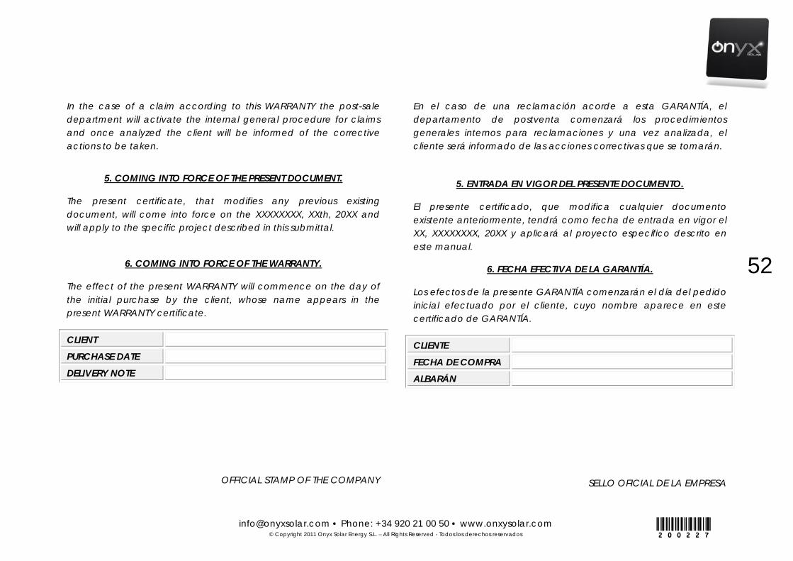
[email protected] • Phone: +34 920 21 00 50 • www.onxysolar.com © Copyright 2011 Onyx Solar Energy S.L. – All Rights Reserved - Todos los derechos reservados
52
200227
In the case of a claim according to this WARRANTY the post-sale department will activate the internal general procedure for claims and once analyzed the client will be informed of the corrective actions to be taken.
5. COMING INTO FORCE OF THE PRESENT DOCUMENT.
The present certificate, that modifies any previous existing document, will come into force on the XXXXXXXX, XXth, 20XX and will apply to the specific project described in this submittal.
6. COMING INTO FORCE OF THE WARRANTY.
The effect of the present WARRANTY will commence on the day of the initial purchase by the client, whose name appears in the present WARRANTY certificate.
CLIENT
PURCHASE DATE
DELIVERY NOTE
OFFICIAL STAMP OF THE COMPANY
En el caso de una reclamación acorde a esta GARANTÍA, el departamento de postventa comenzará los procedimientos generales internos para reclamaciones y una vez analizada, el cliente será informado de las acciones correctivas que se tomarán.
5. ENTRADA EN VIGOR DEL PRESENTE DOCUMENTO.
El presente certificado, que modifica cualquier documento existente anteriormente, tendrá como fecha de entrada en vigor el XX, XXXXXXXX, 20XX y aplicará al proyecto específico descrito en este manual.
6. FECHA EFECTIVA DE LA GARANTÍA.
Los efectos de la presente GARANTÍA comenzarán el día del pedido inicial efectuado por el cliente, cuyo nombre aparece en este certificado de GARANTÍA.
CLIENTE
FECHA DE COMPRA
ALBARÁN
SELLO OFICIAL DE LA EMPRESA

[email protected] • Phone: +34 920 21 00 50 • www.onxysolar.com © Copyright 2011 Onyx Solar Energy S.L. – All Rights Reserved - Todos los derechos reservados
53
200227
ANNEX I: JUNCTION BOXES AND WIRING SPECIFICATIONS ANEXO I: ESPECIFICACIONES DE LAS CAJAS DE CONEXIONES Y CABLEADO
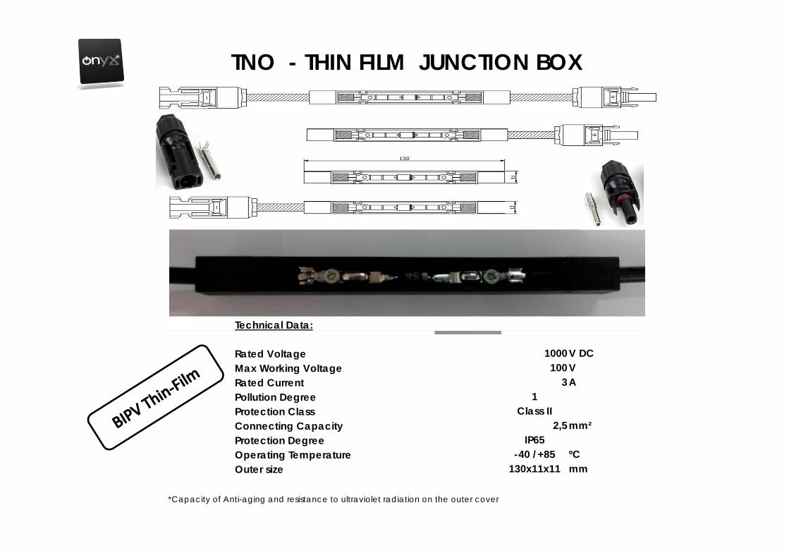
TNO - THIN FILM JUNCTION BOX
Technical Data:
Rated Voltage 1000V DCMax Working Voltage 100V Rated Current 3APollution Degree 1Protection Class Class IIConnecting Capacity 2,5mm²Protection Degree IP65Operating Temperature -40 /+85 ºCOuter size 130x11x11 mm
*Capacity of Anti-aging and resistance to ultraviolet radiation on the outer cover

TNO - THIN FILM JUNCTION BOX
Technical Data:
Rated Voltage 1000 V DCMax Working Voltage 100 V Rated Current 9 APollution Degree 1Protection Class Class IIConnecting Capacity 4 mm²Protection Degree IP65Operating Temperature -40 /+85 ºCOuter size 130x11x11 mm
*Capacity of Anti-aging and resistance to ultraviolet radiation on the outer cover
Multi-Contact
PV-JB/WL-V CRISTALINO
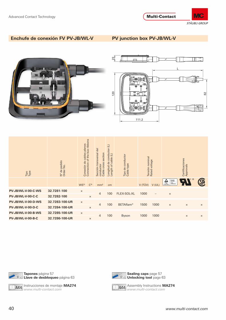
Advanced Contact Technology
40 www.multi-contact.com
Sealing caps page 57 Unlocking tool page 63
MAIch bin eine Montageanleitung.
Man sollte mich unbedingt le-
sen, bevor man das Produkt ver-
wendet! Ich beinhalte wertvolle
Hinweise zur korrekten Montage
und zum richtigen Einsatz des
Produktes. Im Moment ist die
Schrift zwar ein bischen klein,
aber später geht das dann ganz
gut zu lesen, da die MA dann
Assembly Instructions MA274 www.multi-contact.com
Tapones página 57Llave de desbloqueo página 63
MAIch bin eine Montageanleitung.
Man sollte mich unbedingt le-
sen, bevor man das Produkt ver-
wendet! Ich beinhalte wertvolle
Hinweise zur korrekten Montage
und zum richtigen Einsatz des
Produktes. Im Moment ist die
Schrift zwar ein bischen klein,
aber später geht das dann ganz
gut zu lesen, da die MA dann
Instrucciones de montaje MA274 www.multi-contact.com
Enchufe de conexión FV PV-JB/WL-V PV junction box PV-JB/WL-V
Tip
oTy
pe
Nº
de
ped
ido
Ord
er N
o.
Co
nex
ión
de
cab
les
pla
no
sC
on
nec
tio
n o
f th
e b
us
rib
bo
ns
Sec
ció
n t
ran
sver
sal d
el
con
du
cto
r
Cab
le c
ross
sec
tio
n
Lon
git
ud
de
con
du
cto
r (L
)Le
ng
th o
f ca
ble
(L)
Tip
o d
e co
nd
uct
or
Cab
le t
ype
Ten
sió
n n
om
inal
R
ated
vo
ltag
e
Cer
tifi
caci
on
esA
pp
rova
lsWS1) C1) mm² cm V (TÜV) V (UL)
2)
PV-JB/WL-V-00-C-WS 32.7281-100 ×4 100 FLEXSOLXL 1000 – ×
PV-JB/WL-V-00-C-C 32.7282-100 ×
PV-JB/WL-V-00-D-WS 32.7283-100-UR ×4 100 BETAflam® 1500 1000 × × ×
PV-JB/WL-V-00-D-C 32.7284-100-UR ×
PV-JB/WL-V-00-B-WS 32.7285-100-UR ×4 100 Byson 1000 1000 × ×
PV-JB/WL-V-00-B-C 32.7286-100-UR ×

Advanced Contact Technology
www.multi-contact.com 41
■ Junction box for electrical connection of vertical ribbon conductors on crystalline modules
■ The low profile construction of the box allows it to be in-stalled directly under the module frame. Ribbon termination is achieved by welding, soldering, or, optionally, by terminal clips.
■ The box is fixed to the panel with silicone. Additional protec-tion given by the projecting cover, which prevents kinking of the cables at the point where they emerge from the cable sleeve.
■ Fully NEC 2011 compliant requiring the special tool PV-MS-PLS to disconnect the cable couplers.
■ Compatible with MC4 ■ Custom versions on request (see page 71): – Individual lead lengths – Equipped with MC3 and MC4 connectors – Cable colours red or blue (only TÜV types) – Can be produced on request with alternative bypass diode
of type VSB2045 10 A. ■ Includes PSA tape strips for fixturing during installation.
1) WS Welding / Soldering C Clamping
2) Depending on cable type3) Other versions on request, see page 71
■ Enchufe de conexión para módulos cristalinos para el contacto eléctrico de bandas de conexión colocadas verticalmente
■ La construcción plana posibilita una instalación del enchufe directamente debajo de la estructura modular de armazón. La conexión se realiza mediante soldadura directa, soldadura con metal de aportación u opcionalmente con bornes.
■ El enchufe se sujeta sobre el panel con silicona. La construc-ción con tapa que sobresale ofrece una protección adicional de las boquillas de paso de los cables que impide que se doblen los cables a la salida de la boquilla de paso.
■ Bloqueo de los conectores conforme a NEC 2011 me-diante cierre snap-in para una seguridad de conexión máxima,desbloqueable sólo con herramienta PV-MS-PLS.
■ Enchufe compatible con MC4 ■ Producciones especiales a pedido (véase página 71): – Longitudes de conductor individuales – Equipamiento con conectores MC3 y MC4 – Colores de conductor: rojo o azul (sólo variante TÜV) – Es posible, a petición, la fabricación con diodo de bypass
alternativo modelo VSB2045 10 A ■ Incluye tiras de cinta adhesiva para fijar durante la instalación.
1) WS Soldadura / Soldadura C Bornes
2) Dependiendo del tipo de conductor3) Otras variantes, a petición, véase página 71
Datos técnicos Technical dataSistema de conectores Connector system MC4-EVO 33)
Corriente nominal Rated current 12 A (SBX3040)3)
Corriente de test 1,25 x I Test current 1,25 × I 15 A
Tensión nominal Rated voltage 1000 V DC / 1500 V DC (IEC)2)
600 V DC / 1000 V DC (UL)2)
Rango de temperatura ambiente Ambient temperature range -40 °C...+85 °CTipo de protección, enchufado
desenchufadoDegree of protection, mated
unmatedIP65 IP2X
Resistencia de contacto de los conectores Contact resistance of plug connectors ≤ 0,35 mΩ (MC4, MC4-EVO 3)≤ 0,5 mΩ (MC3)
Material de contacto Contact material Cobre, estañado Copper, tin plated
Material aislante Insulation material PPEConectores del sistema de bloqueo Locking system plug connectors (UL) Locking typeClase de inflamabilidad Flame class UL94-5VAResistencia al amoníaco (conforme a DLG) Ammonia resistance (acc. to DLG) 1500 h, 70 °C / 70 % RH, 750 ppmTest de rociado con niebla salina grado de intensidad 5 Salt mist spray test, degree of severity 5 IEC 60068-2-52
Certificación de TÜV Componente reconocido según la norma UL 4703 Certificación de la CSA conforme a la norma UL 4703
TÜV certified UL recognized component, in accordance with UL 4703CSA certified according, in accordance with UL 4703
R60040598 E335016
250725
Adecuado para tipo de módulo Intended for Module type Cristalino / CrystallinePolos Poles 2Diodos Diodes 3Cantidad de cables planos Number of bus ribbons 4Orientación de los cables planos Orientation of bus ribbons Vertical / Vertical
Conexión de cables planos Connection of the bus ribbons Soldadura / Soldadura / Bornes Welding / Soldering / Clamping
Instalación Instalación Silicona / SiliconeApropiado para montaje automático Suitable for semi-automated assembly Sí / Yes
QC
091721-B-02Series(THIN FILM) MONOPOLAR Y BIPOLAR
