35bd moduboot 35sr moduboot ceiling mounted diffusers for ... · 35bd moduboot 35sr moduboot...
TRANSCRIPT
35BD Moduboot35SR ModubootCeiling Mounted Diffusersfor Variable Air VolumeSystems
Selection Manual
1 - INTRODUCTION.........................................................................................................................................................................41.1 - General .........................................................................................................................................................................................41.2 - Comparative air diffusion tests ....................................................................................................................................................41.3 - Air Distribution ............................................................................................................................................................................51.4 - Technical description....................................................................................................................................................................71.5 - Optimix® Moduboot.....................................................................................................................................................................81.6 - Diffuser Types ..............................................................................................................................................................................91.7 - Total Quality...............................................................................................................................................................................11
2 - INTEGRATION OF MODUBOOTS WITH FALSE CEILINGS..........................................................................................112.1 - T-bar ceilings..............................................................................................................................................................................122.2 - Fixed plaster ceilings..................................................................................................................................................................122.3 - Open lattice ceilings ...................................................................................................................................................................13
3 - AIR THROW...............................................................................................................................................................................133.1 - Using the air throw curves .........................................................................................................................................................13
4 - SOUND LEVELS ........................................................................................................................................................................14
5 - SELECTION GUIDE .................................................................................................................................................................165.1 - Preliminary.................................................................................................................................................................................165.2 - Selection procedure ....................................................................................................................................................................16
6 - CODIFICATION.........................................................................................................................................................................176.1 - Supply or return air Moduboot...................................................................................................................................................176.2 - Supply/return air Moduboot .......................................................................................................................................................17
7 - PACKING ....................................................................................................................................................................................207.1 - Moduboot packing .....................................................................................................................................................................207.2 - Return air and dummy diffusers packing ...................................................................................................................................207.3 - Reception....................................................................................................................................................................................20
8 - PHYSICAL AND PERFORMANCE DATA.......................................................................................................................20-87
9 - ACCESSORIES...........................................................................................................................................................................889.1 - Return air diffuser ......................................................................................................................................................................889.2 - Dummy diffuser .........................................................................................................................................................................919.3 - Installation accessories...............................................................................................................................................................92
10 - SPECIAL APPLICATIONS.....................................................................................................................................................9410.1 - Diffuser length..........................................................................................................................................................................9410.2 - Diffuser finish ..........................................................................................................................................................................9410.3 - Diffuser profile .........................................................................................................................................................................9410.4 - Plenum......................................................................................................................................................................................9410.5 - Active diffuser length...............................................................................................................................................................9410.6 - Master/slave arrangement ........................................................................................................................................................95
11 - GUIDE SPECIFICATION .......................................................................................................................................................96
The photograph of the Moduboots shown on the front cover is for illustrative purposes only and is not part of any offer forsale or contract. The manufacturer reserves the right to change the design at any moment without prior warning.
List of contents
35BD units Models Diffuser length Page
Moduboot supply or return air 2 slot ....................................... AG............................................................................................600 mm.............................................21Moduboot supply or return air 2 slot ....................................... AG............................................................................................600 mm.............................................22Moduboot supply or return air 2 slot ....................................... AH............................................................................................600 mm.............................................23Moduboot supply or return air 3 slot ....................................... VH/MH ....................................................................................600 mm.............................................24Moduboot supply or return air 4 slot ....................................... GH/JH ......................................................................................600 mm.............................................25Moduboot supply or return air 5 slot ....................................... BH/QH .....................................................................................600 mm.............................................26Moduboot supply or return air 5 slot ....................................... CH ............................................................................................600 mm.............................................27
Moduboot supply or return air 2 slot ....................................... AG............................................................................................1200 mm...........................................28Moduboot supply or return air 2 slot ....................................... AG............................................................................................1200 mm...........................................29
Moduboot supply or return air 2 slot .......................................AH.............................................................................................1200-1350 mm .................................30Moduboot supply or return air 3 slot .......................................VH/MH .....................................................................................1200-1350 mm .................................31Moduboot supply air Optimix® 3 slot.....................................SH..............................................................................................1200-1350 mm .................................32Moduboot supply air Optimix® 3 slot.....................................EH/FH .......................................................................................1200-1350 mm .................................33Moduboot supply or return air 4 slot .......................................GH/JH .......................................................................................1200-1350 mm .................................34Moduboot supply air Optimix® 4 slot.....................................KH/XH ......................................................................................1200-1350 mm .................................35Moduboot supply air Optimix® 4 slot.....................................UH.............................................................................................1200-1350 mm .................................36Moduboot supply or return air 5 slot .......................................BH/QH ......................................................................................1200-1350 mm .................................37Moduboot supply or return air 5 slot .......................................CH .............................................................................................1200-1350 mm .................................38Moduboot supply air Optimix® 5 slot.....................................LH/NH ......................................................................................1200-1350 mm .................................39
Moduboot supply or return air 2 slot .......................................AG.............................................................................................1500 mm...........................................40Moduboot supply or return air 2 slot .......................................AG.............................................................................................1500 mm...........................................41Moduboot supply or return air 2 slot .......................................AH.............................................................................................1500 mm...........................................42Moduboot supply or return air 3 slot .......................................VH/MH ....................................................................................1500 mm...........................................43Moduboot supply air Optimix® 3 slot.....................................SH..............................................................................................1500 mm...........................................44Moduboot supply air Optimix® 3 slot.....................................EH/FH .......................................................................................1500 mm...........................................45Moduboot supply or return air 4 slot .......................................GH/JH .......................................................................................1500 mm...........................................46Moduboot supply air Optimix® 4 slot.....................................KH/XH ......................................................................................1500 mm...........................................47Moduboot supply air Optimix® 4 slot.....................................UH.............................................................................................1500 mm...........................................48Moduboot supply or return air 5 slot .......................................BH/QH ......................................................................................1500 mm...........................................49Moduboot supply or return air 5 slot .......................................CH .............................................................................................1500 mm.......................................... 50Moduboot supply air Optimix® 5 slot.....................................LH/NH ......................................................................................1500 mm.......................................... 51
35SR units Models Diffuser length Page
Moduboot supply/return air 3 slot ...........................................VH/MH .....................................................................................1200-1350 mm .................................52Moduboot supply/return air Optimix® 3 slot ..........................EH/FH .......................................................................................1200-1350 mm ................................ 53Moduboot supply/return air Optimix® 3 slot ..........................SH..............................................................................................1200-1350 mm .................................54Moduboot supply/return air 4 slot ...........................................GH.............................................................................................1200-1350 mm ................................ 55Moduboot supply/return air 4 slot ...........................................JH ..............................................................................................1200-1350 mm .................................56Moduboot supply/return air Optimix® 4 slot ..........................XH.............................................................................................1200-1350 mm .................................57Moduboot supply/return air Optimix® 4 slot ..........................UH.............................................................................................1200-1350 mm .................................58Moduboot supply/return air Optimix® 4 slot ..........................KH.............................................................................................1200-1350 mm .................................59Moduboot supply/return air 5 slot ...........................................CH/QH ......................................................................................1200-1350 mm ................................60Moduboot supply/return air 5 slot ...........................................BH .............................................................................................1200-1350 mm .................................61Moduboot supply/return air Optimix® 5 slot ..........................LH .............................................................................................1200-1350 mm ................................62Moduboot supply/return air Optimix® 5 slot ..........................NH.............................................................................................1200-1350 mm .................................63
Moduboot supply/return air 3 slot ...........................................VH/MH .....................................................................................1500 mm...........................................64Moduboot supply/return air Optimix® 3 slot ..........................EH/FH .......................................................................................1500 mm.......................................... 65Moduboot supply/return air Optimix® 3 slot ..........................SH..............................................................................................1500 mm...........................................66Moduboot supply/return air 4 slot ...........................................GH.............................................................................................1500 mm.......................................... 67Moduboot supply/return air 4 slot ...........................................JH ..............................................................................................1500 mm...........................................68Moduboot supply/return air Optimix® 4 slot ..........................XH.............................................................................................1500 mm...........................................69Moduboot supply/return air Optimix® 4 slot ..........................UH.............................................................................................1500 mm...........................................70Moduboot supply/return air Optimix® 4 slot ..........................KH.............................................................................................1500 mm...........................................71Moduboot supply/return air 5 slot ...........................................CH/QH ......................................................................................1500 mm...........................................72Moduboot supply/return air 5 slot ...........................................BH .............................................................................................1500 mm...........................................73Moduboot supply/return air Optimix® 5 slot ..........................LH .............................................................................................1500 mm...........................................74Moduboot supply/return air Optimix® 5 slot ..........................NH.............................................................................................1500 mm...........................................75
Moduboot supply/return air 3 slot ...........................................VH/MH .....................................................................................1800 mm...........................................76Moduboot supply/return air Optimix® 3 slot ..........................EH/FH .......................................................................................1800 mm...........................................77Moduboot supply/return air Optimix® 3 slot ..........................SH..............................................................................................1800 mm...........................................78Moduboot supply/return air 4 slot ...........................................GH.............................................................................................1800 mm...........................................79Moduboot supply/return air 4 slot ...........................................JH ..............................................................................................1800 mm...........................................80Moduboot supply/return air Optimix® 4 slot ..........................XH.............................................................................................1800 mm...........................................81Moduboot supply/return air Optimix® 4 slot ..........................KH.............................................................................................1800 mm...........................................82Moduboot supply/return air Optimix® 4 slot ..........................UH.............................................................................................1800 mm...........................................83Moduboot supply/return air 5 slot ...........................................BH .............................................................................................1800 mm...........................................84Moduboot supply/return air 5 slot ...........................................CH/QH ......................................................................................1800 mm...........................................85Moduboot supply/return air Optimix® 5 slot ..........................NH.............................................................................................1800 mm...........................................86Moduboot supply/return air Optimix® 5 slot ..........................LH .............................................................................................1800 mm...........................................87
Index
4
1 - INTRODUCTION
1.1 - General
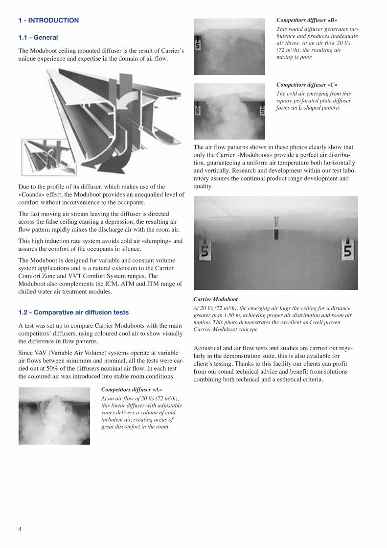
The Moduboot ceiling mounted diffuser is the result of Carrier�sunique experience and expertise in the domain of air flow.
Due to the profile of its diffuser, which makes use of the«Coanda» effect, the Moduboot provides an unequalled level ofcomfort without inconvenience to the occupants.
The fast moving air stream leaving the diffuser is directedacross the false ceiling causing a depression, the resulting airflow pattern rapidly mixes the discharge air with the room air.
This high induction rate system avoids cold air «dumping» andassures the comfort of the occupants in silence.
The Moduboot is designed for variable and constant volumesystem applications and is a natural extension to the CarrierComfort Zone and VVT Comfort System ranges. TheModuboot also complements the ICM, ATM and ITM range ofchilled water air treatment modules.
1.2 - Comparative air diffusion tests
A test was set up to compare Carrier Moduboots with the maincompetitors� diffusers, using coloured cool air to show visuallythe difference in flow patterns.
Since VAV (Variable Air Volume) systems operate at variableair flows between minimum and nominal, all the tests were car-ried out at 50% of the diffusers nominal air flow. In each testthe coloured air was introduced into stable room conditions.
The air flow patterns shown in these photos clearly show thatonly the Carrier «Moduboots» provide a perfect air distribu-tion, guaranteeing a uniform air temperature both horizontallyand vertically. Research and development within our test labo-ratory assures the continual product range development andquality.
Carrier Moduboot
At 20 l/s (72 m3/h), the emerging air hugs the ceiling for a distancegreater than 1.50 m, achieving proper air distribution and room airmotion. This photo demonstrates the excellent and well provenCarrier Moduboot concept.
Acoustical and air flow tests and studies are carried out regu-larly in the demonstration suite, this is also available forclient�s testing. Thanks to this facility our clients can profitfrom our sound technical advice and benefit from solutionscombining both technical and a esthetical criteria.
Competitors diffuser «A»
At an air flow of 20 l/s (72 m3/h),this linear diffuser with adjustablevanes delivers a column of coldturbulent air, creating areas ofgreat discomfort in the room.
Competitors diffuser «B»
This round diffuser generates tur-bulence and produces inadequateair throw. At an air flow 20 l/s(72 m3/h), the resulting airmixing is poor.
Competitors diffuser «C»
The cold air emerging from thissquare perforated plate diffuserforms an L-shaped pattern.
5
1.3 - Air Distribution
Air distribution is a fundamental comfort factor.
The Carrier «Moduboot» diffuser uses the «Coanda» effect forair distribution.
The design of the Carrier Moduboot linear diffuser maintainsthe Coanda effect down to 15% of nominal unit air flow. Atlower air flows, the air velocity is such that the air feels still,and cold air drafts are avoided. At lower air flows it is unlikelythat the space would be occupied, since it is mainly the occu-pants, lighting and other internal gains that make up the spaceheat load.
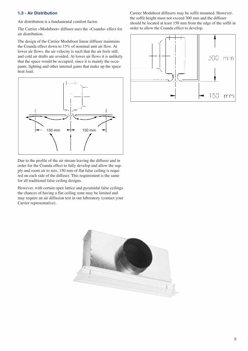
Due to the profile of the air stream leaving the diffuser and inorder for the Coanda effect to fully develop and allow the sup-ply and room air to mix, 150 mm of flat false ceiling is requi-red on each side of the diffuser. This requirement is the samefor all traditional false ceiling designs.
However, with certain open lattice and pyramidal false ceilingsthe chances of having a flat ceiling zone may be limited andmay require an air diffusion test in our laboratory (contact yourCarrier representative).
Carrier Moduboot diffusers may be soffit mounted. However,the soffit height must not exceed 300 mm and the diffusershould be located at least 150 mm from the edge of the soffit inorder to allow the Coanda effect to develop.
150 mm 150 mm
6
1.3.1 - Air distribution models
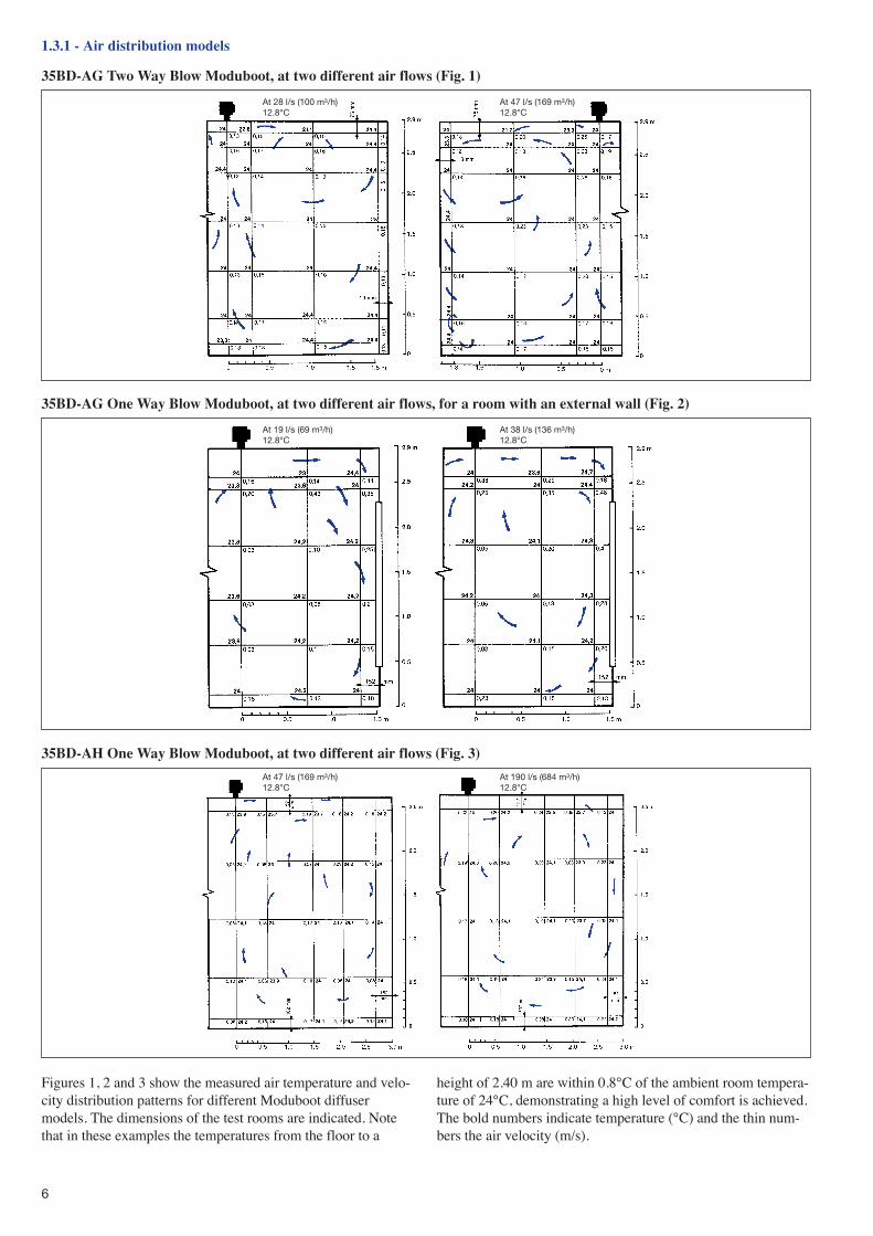
35BD-AG Two Way Blow Moduboot, at two different air flows (Fig. 1)
Figures 1, 2 and 3 show the measured air temperature and velo-city distribution patterns for different Moduboot diffusermodels. The dimensions of the test rooms are indicated. Notethat in these examples the temperatures from the floor to a
height of 2.40 m are within 0.8°C of the ambient room tempera-ture of 24°C, demonstrating a high level of comfort is achieved.The bold numbers indicate temperature (°C) and the thin num-bers the air velocity (m/s).
35BD-AG One Way Blow Moduboot, at two different air flows, for a room with an external wall (Fig. 2)
35BD-AH One Way Blow Moduboot, at two different air flows (Fig. 3)
At 28 l/s (100 m3/h)12.8°C
At 47 l/s (169 m3/h)12.8°C
At 19 l/s (69 m3/h)12.8°C
At 38 l/s (136 m3/h)12.8°C
At 47 l/s (169 m3/h)12.8°C
At 190 l/s (684 m3/h)12.8°C
7
NOTE:Due to excellent air distribution and the high induction rateresulting from the Coanda effect, Moduboots permit tempera-ture differences of up to 14 K between the supply and roomair without causing any discomfort to the occupants.
1.4 - Technical description
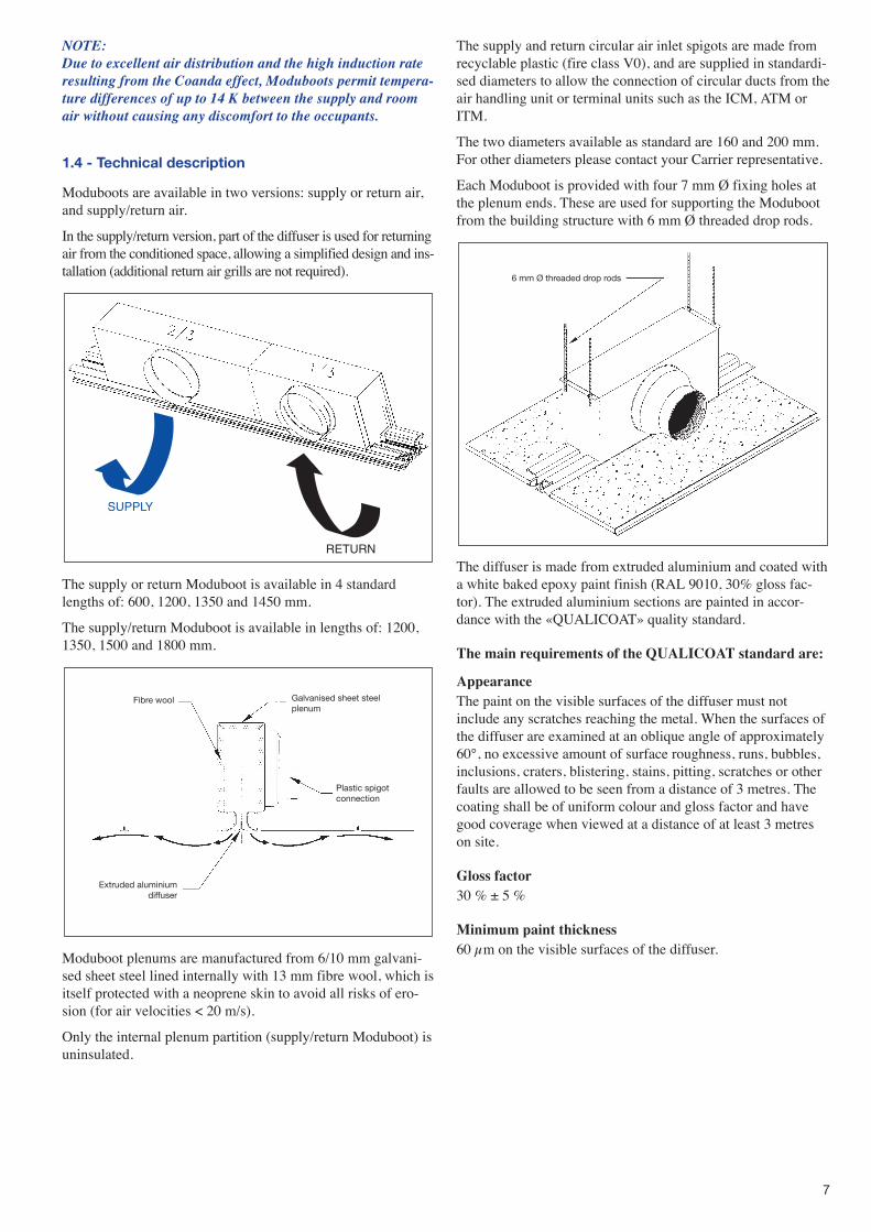
Moduboots are available in two versions: supply or return air,and supply/return air.
In the supply/return version, part of the diffuser is used for returningair from the conditioned space, allowing a simplified design and ins-tallation (additional return air grills are not required).
The supply or return Moduboot is available in 4 standardlengths of: 600, 1200, 1350 and 1450 mm.
The supply/return Moduboot is available in lengths of: 1200,1350, 1500 and 1800 mm.
Moduboot plenums are manufactured from 6/10 mm galvani-sed sheet steel lined internally with 13 mm fibre wool, which isitself protected with a neoprene skin to avoid all risks of ero-sion (for air velocities < 20 m/s).
Only the internal plenum partition (supply/return Moduboot) isuninsulated.
The supply and return circular air inlet spigots are made fromrecyclable plastic (fire class V0), and are supplied in standardi-sed diameters to allow the connection of circular ducts from theair handling unit or terminal units such as the ICM, ATM orITM.
The two diameters available as standard are 160 and 200 mm.For other diameters please contact your Carrier representative.
Each Moduboot is provided with four 7 mm Ø fixing holes atthe plenum ends. These are used for supporting the Modubootfrom the building structure with 6 mm Ø threaded drop rods.
The diffuser is made from extruded aluminium and coated witha white baked epoxy paint finish (RAL 9010, 30% gloss fac-tor). The extruded aluminium sections are painted in accor-dance with the «QUALICOAT» quality standard.
The main requirements of the QUALICOAT standard are:
AppearanceThe paint on the visible surfaces of the diffuser must notinclude any scratches reaching the metal. When the surfaces ofthe diffuser are examined at an oblique angle of approximately60°, no excessive amount of surface roughness, runs, bubbles,inclusions, craters, blistering, stains, pitting, scratches or otherfaults are allowed to be seen from a distance of 3 metres. Thecoating shall be of uniform colour and gloss factor and havegood coverage when viewed at a distance of at least 3 metreson site.
Gloss factor30 % ± 5 %
Minimum paint thickness60 µm on the visible surfaces of the diffuser.
Fibre wool Galvanised sheet steelplenum
Plastic spigotconnection
Extruded aluminiumdiffuser
6 mm Ø threaded drop rods
SUPPLY
RETURN
8
NOTE:The Moduboot diffusers are manufactured from extruded alu-minium sections. During the fabrication process these sectionsare painted and then cut to the required length before beingassembled. Consequently the ends of the finished diffuser arenot covered with paint.
It is important to take this into account when installing the dif-fusers in the false ceiling, and when selecting the accessories(see the sections �integration of the diffusers in the false cei-ling�).
The diffusers are available with 2, 3, 4 or 5 slots and with orwithout the �Optimix®� damper blade.
The painted part of the diffuser is protected by a pealable adhe-sive strip, it is recommended that this be left in place until theinstallation is finished in order to protect the diffuser againstany possible damage.
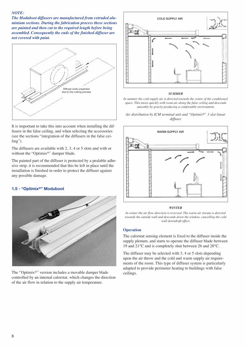
1.5 - “Optimix®” Moduboot
The �Optimix®� version includes a movable damper bladecontrolled by an internal calorstat, which changes the directionof the air flow in relation to the supply air temperature.
SUMMER
In summer the cold supply air is directed towards the centre of the conditionedspace. This mixes quickly with room air along the false ceiling and descends
smoothly by gravity producing a comfortable environment.
Air distribution by ICM terminal unit and “Optimix®” 3 slot lineardiffuser.
WINTER
In winter the air flow direction is reversed. The warm air stream is directedtowards the outside wall and descends down the window, cancelling the cold
wall downdraft effect.
Operation
The calorstat sensing element is fixed to the diffuser inside thesupply plenum, and starts to operate the diffuser blade between19 and 21°C and is completely shut between 26 and 28°C.
The diffuser may be selected with 3, 4 or 5 slots dependingupon the air throw and the cold and warm supply air require-ments of the room. This type of diffuser system is particularlyadapted to provide perimeter heating to buildings with falseceilings.
Diffuser ends unpainteddue to the cutting process
COLD SUPPLY AIR
WARM SUPPLY AIR
9
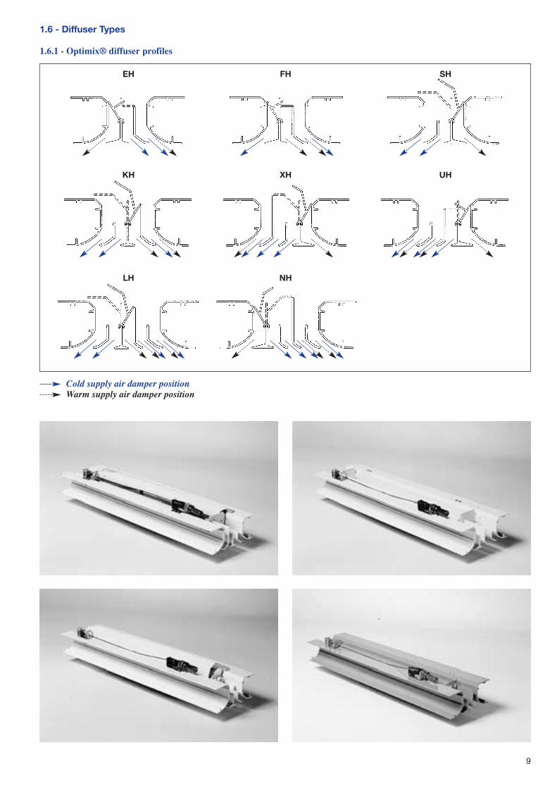
1.6 - Diffuser Types
1.6.1 - Optimix® diffuser profiles
EH FH SH
KH XH UH
LH NH
Cold supply air damper positionWarm supply air damper position
10
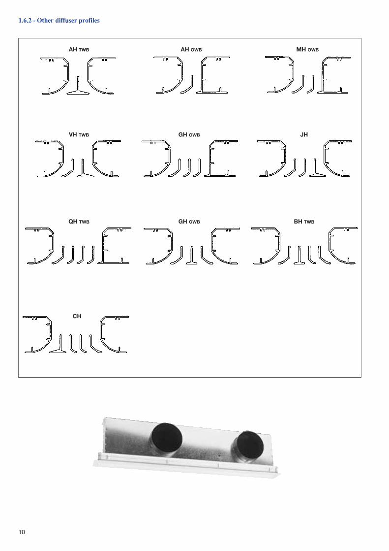
1.6.2 - Other diffuser profiles
AH TWB
VH TWB GH OWB JH
QH TWB
CH
GH OWB BH TWB
AH OWB MH OWB
11
1.7 - Total Quality
Carrier�s total quality concept is not just limited to the product quality but extends also to the design, performance reliability andfabrication processes.
Units are tested in Carrier�s own research and development laboratory and/or at the �Centre Technique des Industries Aérauliqueset Thermiques� (CETIAT), guaranteeing the quality of the performance data; Carrier has been accredited with L.R.Q.A. certifica-tion in accordance with the standard ISO 9001 since 1989.
ISO 9001 certification encompasses product design, production and delivery and also after sales support.
2 - INTEGRATION OF MODUBOOTS IN FALSECEILINGS
Carrier Moduboots integrate perfectly with all types of falseceiling where they are practically invisible with only the dis-creet white profile of the aluminium diffuser being noticeable.
The diffuser can be used to support the false ceiling andbecome an integral part of the ceiling decoration (maximumload per metre length: 15 kg/m).
Moduboots are compatible with most currently available falseceiling designs.� T-bar, both exposed and hidden T-bar � Plaster� Open lattice
Moduboots should ideally be positioned parallel to the perime-ter wall, either using a TWB diffuser installed in the middle ofthe room or OWB diffuser installed near to the perimeter.
The exceptional characteristics of the diffuser and wide airflow range provide the Moduboot with a high degree installa-tion flexibility.
The proximity of light fittings, misalignment of the false cei-ling or any other objects projecting less than 15 mm will notaffect the diffusion performance.
In every case the orientation of the T-bar, the false ceilingmodule and the location of the light fittings will always governthe position of the Moduboots.
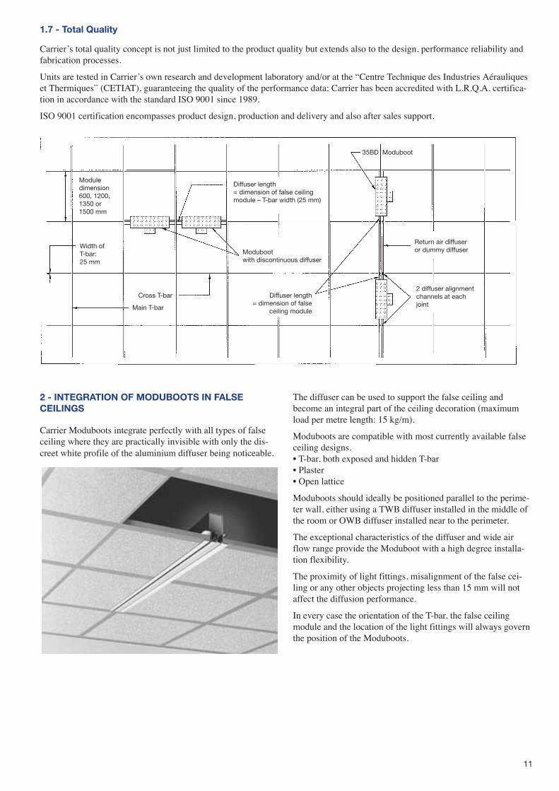
Moduledimension600, 1200,1350 or1500 mm
Diffuser length= dimension of false ceilingmodule – T-bar width (25 mm)
Diffuser length= dimension of false
ceiling module
Moduboot with discontinuous diffuser
Width ofT-bar:25 mm
35BD Moduboot
Return air diffuser or dummy diffuser
2 diffuser alignmentchannels at eachjoint
Cross T-bar
Main T-bar
12
2.1 - Integration of Moduboots in T-bar ceilings
Exposed T-bar false ceilings are made up from �T� shapedmetal profiles suspended inverted by wire hangers or drop rods.
The T-bars are positioned at standard intervals of 600, 1200,1350, or 1500 mm. T-bar cross members are located betweenthe main T-bar members to form the ceiling design.
2.1.1 - Continuous T-bar ceilings
In these ceiling systems the Moduboots, return air diffusers andthe dummy diffusers are installed in a continuous line parallelwith the main the T-bar members. The diffusers are installedend to end, each one having the same length as the ceilingmodule. With this arrangement T-bar end and filler trim acces-sories are not required.
Continuous diffuser arrangement
The diffusers are aligned using 2 diffuser alignment channels ateach joint (available as accessory items).
2.1.2 - Discontinuous T-bar ceilings
With these ceiling systems the Moduboots, return air diffusers,and dummy diffuser are installed perpendicular to the main T-bar ceiling members. The ends of adjacent diffusers are separa-ted by the width of the T-bar. The diffusers are aligned using T-bar mounting brackets at each diffuser end. With this arrange-ment T-bar end and filler trim accessories are not required.
Discontinuous diffuser arrangement
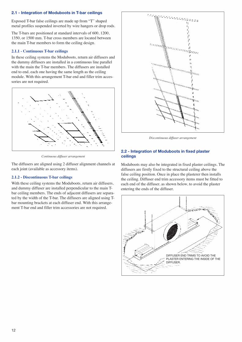
2.2 - Integration of Moduboots in fixed plasterceilings
Moduboots may also be integrated in fixed plaster ceilings. Thediffusers are firstly fixed to the structural ceiling above thefalse ceiling position. Once in place the plasterer then installsthe ceiling. Diffuser end trim accessory items must be fitted toeach end of the diffuser, as shown below, to avoid the plasterentering the ends of the diffuser.
DIFFUSER END TRIMS TO AVOID THEPLASTER ENTERING THE INSIDE OF THEDIFFUSER.
13
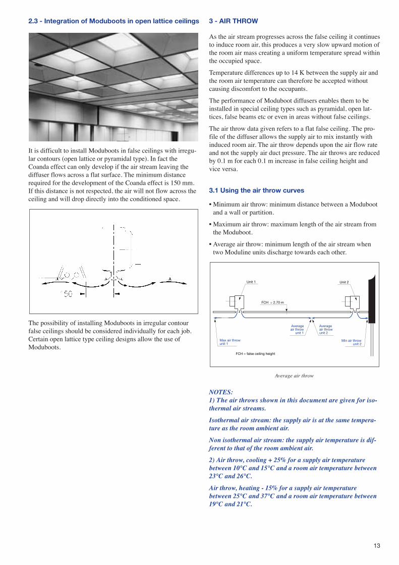
2.3 - Integration of Moduboots in open lattice ceilings
It is difficult to install Moduboots in false ceilings with irregu-lar contours (open lattice or pyramidal type). In fact theCoanda effect can only develop if the air stream leaving thediffuser flows across a flat surface. The minimum distancerequired for the development of the Coanda effect is 150 mm.If this distance is not respected, the air will not flow across theceiling and will drop directly into the conditioned space.
The possibility of installing Moduboots in irregular contourfalse ceilings should be considered individually for each job.Certain open lattice type ceiling designs allow the use ofModuboots.
3 - AIR THROW
As the air stream progresses across the false ceiling it continuesto induce room air, this produces a very slow upward motion ofthe room air mass creating a uniform temperature spread withinthe occupied space.
Temperature differences up to 14 K between the supply air andthe room air temperature can therefore be accepted withoutcausing discomfort to the occupants.
The performance of Moduboot diffusers enables them to beinstalled in special ceiling types such as pyramidal, open lat-tices, false beams etc or even in areas without false ceilings.
The air throw data given refers to a flat false ceiling. The pro-file of the diffuser allows the supply air to mix instantly withinduced room air. The air throw depends upon the air flow rateand not the supply air duct pressure. The air throws are reducedby 0.1 m for each 0.1 m increase in false ceiling height andvice versa.
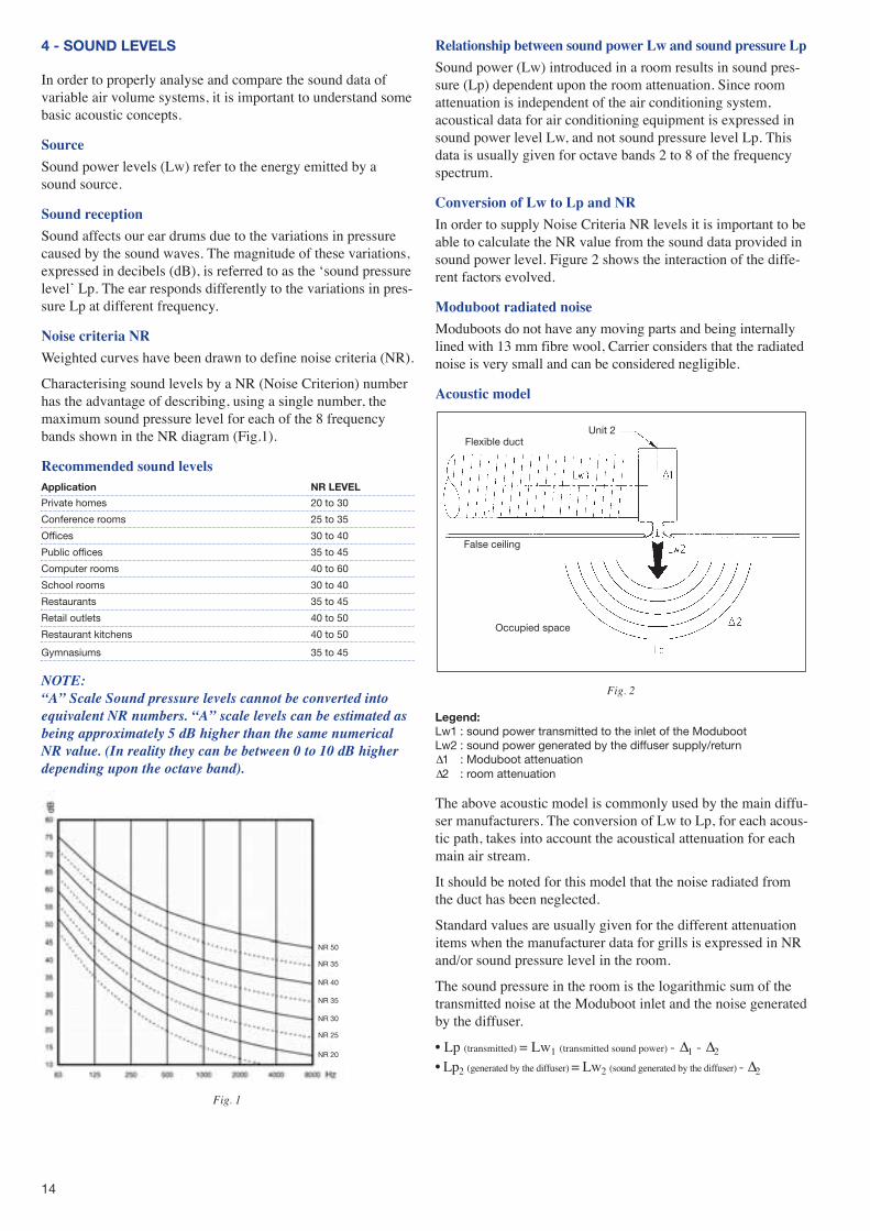
3.1 Using the air throw curves
� Minimum air throw: minimum distance between a Modubootand a wall or partition.
� Maximum air throw: maximum length of the air stream fromthe Moduboot.
� Average air throw: minimum length of the air stream whentwo Moduline units discharge towards each other.
Average air throw
NOTES:1) The air throws shown in this document are given for iso-thermal air streams.
Isothermal air stream: the supply air is at the same tempera-ture as the room ambient air.
Non isothermal air stream: the supply air temperature is dif-ferent to that of the room ambient air.
2) Air throw, cooling + 25% for a supply air temperature between 10°C and 15°C and a room air temperature between23°C and 26°C.
Air throw, heating - 15% for a supply air temperature between 25°C and 37°C and a room air temperature between19°C and 21°C.
Averageair throwunit 2
Averageair throw
unit 1
Min air throwunit 2
Max air throwunit 1
FCH = 2.70 m
Unit 1 Unit 2
FCH = false ceiling height
14
4 - SOUND LEVELS
In order to properly analyse and compare the sound data ofvariable air volume systems, it is important to understand somebasic acoustic concepts.
Source
Sound power levels (Lw) refer to the energy emitted by asound source.
Sound reception
Sound affects our ear drums due to the variations in pressurecaused by the sound waves. The magnitude of these variations,expressed in decibels (dB), is referred to as the �sound pressurelevel� Lp. The ear responds differently to the variations in pres-sure Lp at different frequency.
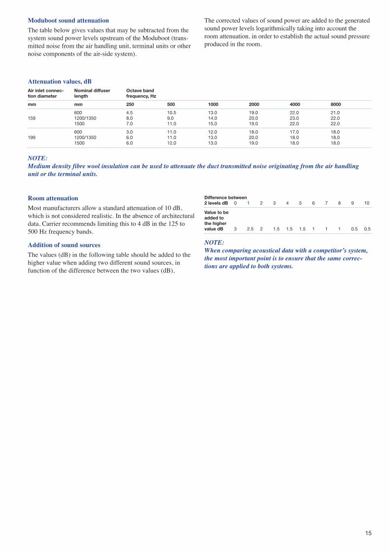
Noise criteria NR
Weighted curves have been drawn to define noise criteria (NR).
Characterising sound levels by a NR (Noise Criterion) numberhas the advantage of describing, using a single number, themaximum sound pressure level for each of the 8 frequencybands shown in the NR diagram (Fig.1).
Recommended sound levelsApplication NR LEVEL
Private homes 20 to 30
Conference rooms 25 to 35
Offices 30 to 40
Public offices 35 to 45
Computer rooms 40 to 60
School rooms 30 to 40
Restaurants 35 to 45
Retail outlets 40 to 50
Restaurant kitchens 40 to 50
Gymnasiums 35 to 45
NOTE:“A” Scale Sound pressure levels cannot be converted intoequivalent NR numbers. “A” scale levels can be estimated asbeing approximately 5 dB higher than the same numericalNR value. (In reality they can be between 0 to 10 dB higherdepending upon the octave band).
Fig. 1
Relationship between sound power Lw and sound pressure Lp
Sound power (Lw) introduced in a room results in sound pres-sure (Lp) dependent upon the room attenuation. Since roomattenuation is independent of the air conditioning system,acoustical data for air conditioning equipment is expressed insound power level Lw, and not sound pressure level Lp. Thisdata is usually given for octave bands 2 to 8 of the frequencyspectrum.
Conversion of Lw to Lp and NR
In order to supply Noise Criteria NR levels it is important to beable to calculate the NR value from the sound data provided insound power level. Figure 2 shows the interaction of the diffe-rent factors evolved.
Moduboot radiated noise
Moduboots do not have any moving parts and being internallylined with 13 mm fibre wool, Carrier considers that the radiatednoise is very small and can be considered negligible.
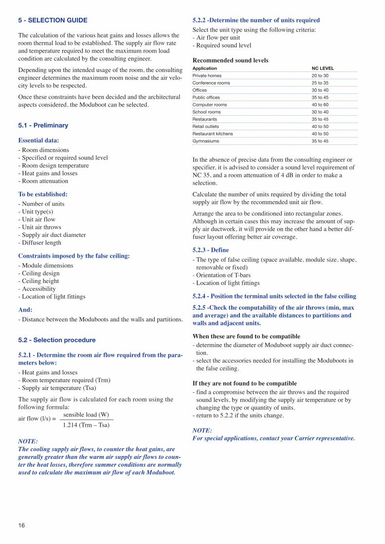
Acoustic model
Fig. 2
Legend:Lw1 : sound power transmitted to the inlet of the ModubootLw2 : sound power generated by the diffuser supply/return∆1 : Moduboot attenuation ∆2 : room attenuation
The above acoustic model is commonly used by the main diffu-ser manufacturers. The conversion of Lw to Lp, for each acous-tic path, takes into account the acoustical attenuation for eachmain air stream.
It should be noted for this model that the noise radiated fromthe duct has been neglected.
Standard values are usually given for the different attenuationitems when the manufacturer data for grills is expressed in NRand/or sound pressure level in the room.
The sound pressure in the room is the logarithmic sum of thetransmitted noise at the Moduboot inlet and the noise generatedby the diffuser.
� Lp (transmitted) = Lw1 (transmitted sound power) - ∆1 - ∆2
� Lp2 (generated by the diffuser) = Lw2 (sound generated by the diffuser) - ∆2
Flexible duct
False ceiling
Occupied space
Unit 2
NR 50
NR 35
NR 40
NR 35
NR 30
NR 25
NR 20
15
Moduboot sound attenuation
The table below gives values that may be subtracted from thesystem sound power levels upstream of the Moduboot (trans-mitted noise from the air handling unit, terminal units or othernoise components of the air-side system).
The corrected values of sound power are added to the generatedsound power levels logarithmically taking into account theroom attenuation, in order to establish the actual sound pressureproduced in the room.
Attenuation values, dBAir inlet connec- Nominal diffuser Octave bandtion diameter length frequency, Hz
mm mm 250 500 1000 2000 4000 8000
600 4.5 10.5 13.0 19.0 22.0 21.0159 1200/1350 8.0 9.0 14.0 20.0 23.0 22.0
1500 7.0 11.0 15.0 19.0 22.0 22.0
600 3.0 11.0 12.0 18.0 17.0 18.0199 1200/1350 6.0 11.0 13.0 20.0 18.0 18.0
1500 6.0 12.0 13.0 19.0 18.0 18.0
NOTE:Medium density fibre wool insulation can be used to attenuate the duct transmitted noise originating from the air handlingunit or the terminal units.
Room attenuation
Most manufacturers allow a standard attenuation of 10 dB,which is not considered realistic. In the absence of architecturaldata, Carrier recommends limiting this to 4 dB in the 125 to500 Hz frequency bands.
Addition of sound sources
The values (dB) in the following table should be added to thehigher value when adding two different sound sources, infunction of the difference between the two values (dB),
Difference between2 levels dB 0 1 2 3 4 5 6 7 8 9 10
Value to beadded tothe higher value dB 3 2.5 2 1.5 1.5 1.5 1 1 1 0.5 0.5
NOTE:When comparing acoustical data with a competitor’s system,the most important point is to ensure that the same correc-tions are applied to both systems.
16
5 - SELECTION GUIDE
The calculation of the various heat gains and losses allows theroom thermal load to be established. The supply air flow rateand temperature required to meet the maximum room loadcondition are calculated by the consulting engineer.
Depending upon the intended usage of the room, the consultingengineer determines the maximum room noise and the air velo-city levels to be respected.
Once these constraints have been decided and the architecturalaspects considered, the Moduboot can be selected.
5.1 - Preliminary
Essential data:
- Room dimensions - Specified or required sound level - Room design temperature- Heat gains and losses- Room attenuation
To be established:
- Number of units- Unit type(s) - Unit air flow- Unit air throws - Supply air duct diameter- Diffuser length
Constraints imposed by the false ceiling:
- Module dimensions - Ceiling design- Ceiling height- Accessibility- Location of light fittings
And:
- Distance between the Moduboots and the walls and partitions.
5.2 - Selection procedure
5.2.1 - Determine the room air flow required from the para-meters below:
- Heat gains and losses- Room temperature required (Trm)- Supply air temperature (Tsa)
The supply air flow is calculated for each room using thefollowing formula:
air flow (l/s) = sensible load (W)
1.214 (Trm � Tsa)
NOTE:The cooling supply air flows, to counter the heat gains, aregenerally greater than the warm air supply air flows to coun-ter the heat losses, therefore summer conditions are normallyused to calculate the maximum air flow of each Moduboot.
5.2.2 -Determine the number of units required
Select the unit type using the following criteria:- Air flow per unit- Required sound level
Recommended sound levelsApplication NC LEVEL
Private homes 20 to 30
Conference rooms 25 to 35
Offices 30 to 40
Public offices 35 to 45
Computer rooms 40 to 60
School rooms 30 to 40
Restaurants 35 to 45
Retail outlets 40 to 50
Restaurant kitchens 40 to 50
Gymnasiums 35 to 45
In the absence of precise data from the consulting engineer orspecifier, it is advised to consider a sound level requirement ofNC 35, and a room attenuation of 4 dB in order to make aselection.
Calculate the number of units required by dividing the totalsupply air flow by the recommended unit air flow.
Arrange the area to be conditioned into rectangular zones.Although in certain cases this may increase the amount of sup-ply air ductwork, it will provide on the other hand a better dif-fuser layout offering better air coverage.
5.2.3 - Define
- The type of false ceiling (space available, module size, shape,removable or fixed)
- Orientation of T-bars- Location of light fittings
5.2.4 - Position the terminal units selected in the false ceiling
5.2.5 -Check the computability of the air throws (min, maxand average) and the available distances to partitions andwalls and adjacent units.
When these are found to be compatible- determine the diameter of Moduboot supply air duct connec-
tion. - select the accessories needed for installing the Moduboots in
the false ceiling.
If they are not found to be compatible- find a compromise between the air throws and the required
sound levels, by modifying the supply air temperature or bychanging the type or quantity of units.
- return to 5.2.2 if the units change.
NOTE:For special applications, contact your Carrier representative.
17
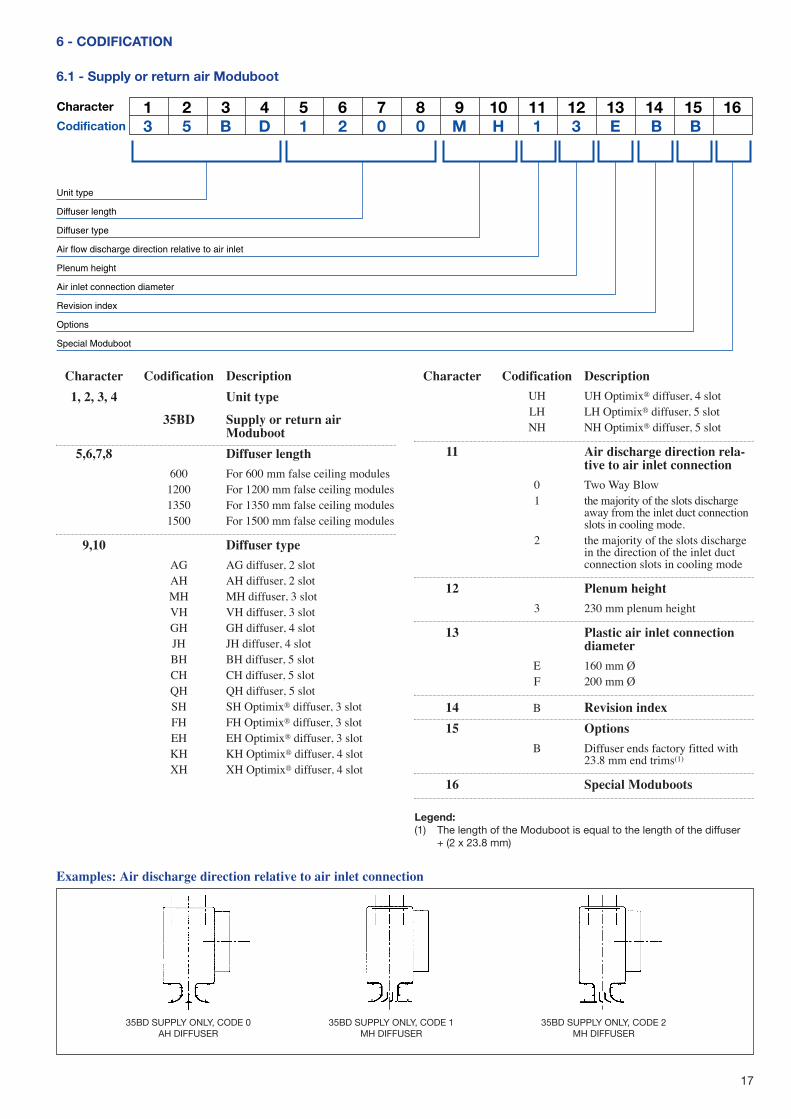
6 - CODIFICATION
6.1 - Supply or return air Moduboot
1 2 3 4 5 6 7 8 9 10 11 12 13 14 15 163 5 B D 1 2 0 0 M H 1 3 E B B
Unit type
Diffuser length
Diffuser type
Air flow discharge direction relative to air inlet
Plenum height
Air inlet connection diameter
Revision index
Options
Special Moduboot
Character
Codification
Character Codification Description
1, 2, 3, 4 Unit type
35BD Supply or return airModuboot
5,6,7,8 Diffuser length
600 For 600 mm false ceiling modules1200 For 1200 mm false ceiling modules1350 For 1350 mm false ceiling modules1500 For 1500 mm false ceiling modules
9,10 Diffuser type
AG AG diffuser, 2 slotAH AH diffuser, 2 slotMH MH diffuser, 3 slotVH VH diffuser, 3 slotGH GH diffuser, 4 slotJH JH diffuser, 4 slotBH BH diffuser, 5 slotCH CH diffuser, 5 slotQH QH diffuser, 5 slotSH SH Optimix® diffuser, 3 slotFH FH Optimix® diffuser, 3 slotEH EH Optimix® diffuser, 3 slotKH KH Optimix® diffuser, 4 slotXH XH Optimix® diffuser, 4 slot
Character Codification Description
UH UH Optimix® diffuser, 4 slotLH LH Optimix® diffuser, 5 slotNH NH Optimix® diffuser, 5 slot
11 Air discharge direction rela-tive to air inlet connection
0 Two Way Blow1 the majority of the slots discharge
away from the inlet duct connectionslots in cooling mode.
2 the majority of the slots dischargein the direction of the inlet ductconnection slots in cooling mode
12 Plenum height
3 230 mm plenum height
13 Plastic air inlet connectiondiameter
E 160 mm ØF 200 mm Ø
14 B Revision index
15 Options
B Diffuser ends factory fitted with23.8 mm end trims(1)
16 Special Moduboots
Examples: Air discharge direction relative to air inlet connection
35BD SUPPLY ONLY, CODE 0AH DIFFUSER
35BD SUPPLY ONLY, CODE 1MH DIFFUSER
35BD SUPPLY ONLY, CODE 2MH DIFFUSER
Legend:(1) The length of the Moduboot is equal to the length of the diffuser
+ (2 x 23.8 mm)
18
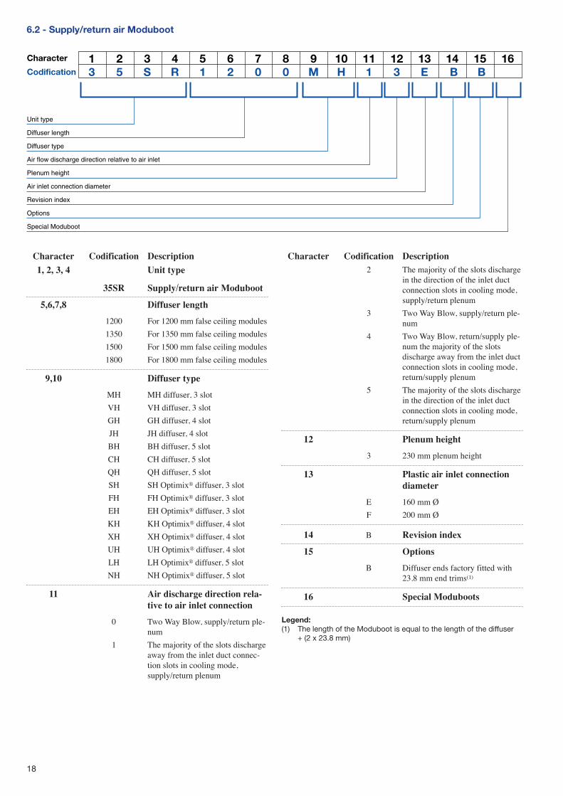
6.2 - Supply/return air Moduboot
1 2 3 4 5 6 7 8 9 10 11 12 13 14 15 163 5 S R 1 2 0 0 M H 1 3 E B B
Unit type
Diffuser length
Diffuser type
Air flow discharge direction relative to air inlet
Plenum height
Air inlet connection diameter
Revision index
Options
Special Moduboot
Character
Codification
Character Codification Description
1, 2, 3, 4 Unit type
35SR Supply/return air Moduboot
5,6,7,8 Diffuser length
1200 For 1200 mm false ceiling modules
1350 For 1350 mm false ceiling modules
1500 For 1500 mm false ceiling modules
1800 For 1800 mm false ceiling modules
9,10 Diffuser type
MH MH diffuser, 3 slot
VH VH diffuser, 3 slot
GH GH diffuser, 4 slot
JH JH diffuser, 4 slot
BH BH diffuser, 5 slot
CH CH diffuser, 5 slot
QH QH diffuser, 5 slot
SH SH Optimix® diffuser, 3 slot
FH FH Optimix® diffuser, 3 slot
EH EH Optimix® diffuser, 3 slot
KH KH Optimix® diffuser, 4 slot
XH XH Optimix® diffuser, 4 slot
UH UH Optimix® diffuser, 4 slot
LH LH Optimix® diffuser, 5 slot
NH NH Optimix® diffuser, 5 slot
11 Air discharge direction rela-tive to air inlet connection
0 Two Way Blow, supply/return ple-num
1 The majority of the slots dischargeaway from the inlet duct connec-tion slots in cooling mode,supply/return plenum
Character Codification Description2 The majority of the slots discharge
in the direction of the inlet ductconnection slots in cooling mode,supply/return plenum
3 Two Way Blow, supply/return ple-num
4 Two Way Blow, return/supply ple-num the majority of the slotsdischarge away from the inlet ductconnection slots in cooling mode,return/supply plenum
5 The majority of the slots dischargein the direction of the inlet ductconnection slots in cooling mode,return/supply plenum
12 Plenum height
3 230 mm plenum height
13 Plastic air inlet connectiondiameter
E 160 mm Ø
F 200 mm Ø
14 B Revision index
15 Options
B Diffuser ends factory fitted with23.8 mm end trims(1)
16 Special Moduboots
Legend:(1) The length of the Moduboot is equal to the length of the diffuser
+ (2 x 23.8 mm)
19
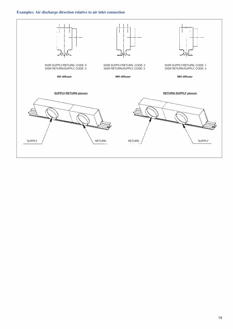
Examples: Air discharge direction relative to air inlet connection
35SR SUPPLY/RETURN, CODE: 035SR RETURN/SUPPLY, CODE: 3
SUPPLY SUPPLYRETURN RETURN
GH diffuser
SUPPLY-RETURN plenum
MH diffuser
RETURN-SUPPLY plenum
MH diffuser
35SR SUPPLY/RETURN, CODE: 235SR RETURN/SUPPLY, CODE: 5
35SR SUPPLY/RETURN, CODE: 135SR RETURN/SUPPLY, CODE: 4
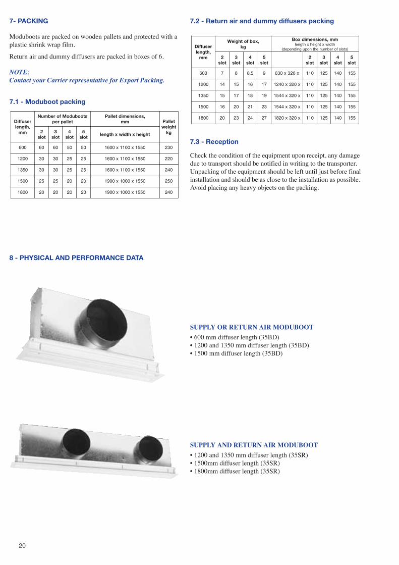
7- PACKING
Moduboots are packed on wooden pallets and protected with aplastic shrink wrap film.
Return air and dummy diffusers are packed in boxes of 6.
NOTE: Contact your Carrier representative for Export Packing.
7.1 - Moduboot packing
resuffiD,htgnel
mm
stoobudoMforebmuNtellaprep
,snoisnemidtellaPmm tellaP
thgiewgk2
tols3
tols4
tols5
tolsthgiehxhtdiwxhtgnel
006 06 06 05 05 0551x0011x0061 032
0021 03 03 52 52 0551x0011x0061 022
0531 03 03 52 52 0551x0011x0061 042
0051 52 52 02 02 0551x0001x0091 052
0081 02 02 02 02 0551x0001x0091 042
7.2 - Return air and dummy diffusers packing
7.3 - Reception
Check the condition of the equipment upon receipt, any damagedue to transport should be notified in writing to the transporter.Unpacking of the equipment should be left until just before finalinstallation and should be as close to the installation as possible.Avoid placing any heavy objects on the packing.
resuffiD,htgnel
mm
,xobfothgieWgk
mm,snoisnemidxoBhtdiwxthgiehxhtgnel
)stolsforebmunehtnopugnidneped(
2tols
3tols
4tols
5tols
2tols
3tols
4tols
5tols
006 7 8 5.8 9 x023x036 011 521 041 551
0021 41 51 61 71 x023x0421 011 521 041 551
0531 51 71 81 91 x023x4451 011 521 041 551
0051 61 02 12 32 x023x4451 011 521 041 551
0081 02 32 42 72 x023x0281 011 521 041 551
8 - PHYSICAL AND PERFORMANCE DATA
SUPPLY OR RETURN AIR MODUBOOT
� 600 mm diffuser length (35BD)� 1200 and 1350 mm diffuser length (35BD)� 1500 mm diffuser length (35BD)
SUPPLY AND RETURN AIR MODUBOOT
� 1200 and 1350 mm diffuser length (35SR)� 1500mm diffuser length (35SR)� 1800mm diffuser length (35SR)
20
21
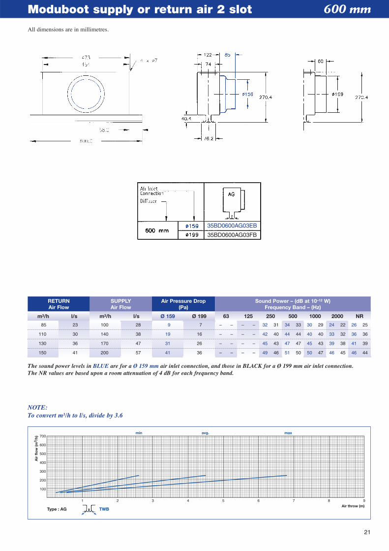
Moduboot supply or return air 2 slot 600 mm
Type : AG TWB
1 2 3 4 5 6 7 8 9Air throw (m)
min avg. max
100
200
300
400
500
600
700
Air
flo
w (m
3 /h)
The sound power levels in BLUE are for a Ø 159 mm air inlet connection, and those in BLACK for a Ø 199 mm air inlet connection.The NR values are based upon a room attenuation of 4 dB for each frequency band.
NOTE:To convert m3/h to l/s, divide by 3.6
RETURNAir Flow
m3/h l/s m3/h l/s Ø 159 Ø 199 63 125 250 500 1000 2000 NR
SUPPLYAir Flow
Air Pressure Drop(Pa)
Sound Power – (dB at 10–12 W)Frequency Band – (Hz)
85 23 100 28 9 7 – – – – 32 31 34 33 30 29 24 22 26 25
110 30 140 38 19 16 – – – – 42 40 44 44 40 40 33 32 36 36
130 36 170 47 31 26 – – – – 45 43 47 47 45 43 39 38 41 39
150 41 200 57 41 36 – – – – 49 46 51 50 50 47 46 45 46 44
35BD0600AG03EB
35BD0600AG03FB
All dimensions are in millimetres.
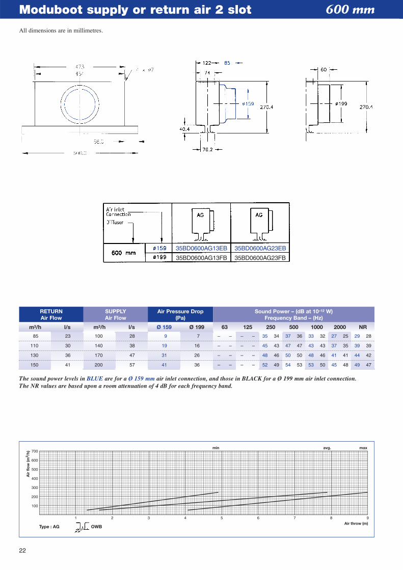
Moduboot supply or return air 2 slot
Type : AG
1 2 3 4 5 6 7 8 9Air throw (m)
min avg. max
100
200
300
400
500
600
700
Air
flo
w (m
3 /h)
OWB
RETURNAir Flow
m3/h l/s m3/h l/s Ø 159 Ø 199 63 125 250 500 1000 2000 NR
SUPPLYAir Flow
Air Pressure Drop(Pa)
Sound Power – (dB at 10–12 W)Frequency Band – (Hz)
The sound power levels in BLUE are for a Ø 159 mm air inlet connection, and those in BLACK for a Ø 199 mm air inlet connection.The NR values are based upon a room attenuation of 4 dB for each frequency band.
85
110
130
150
100
140
170
200
9
19
31
41
7
16
26
36
–
–
–
–
–
–
–
–
–
–
–
–
–
–
–
–
35
45
48
52
34
43
46
49
36
47
50
53
32
43
46
50
25
35
41
48
28
39
42
47
37
47
50
54
33
43
48
53
27
37
41
45
29
39
44
49
23
30
36
41
28
38
47
57
600 mm
35BD0600AG13EB
35BD0600AG13FB
35BD0600AG23EB
35BD0600AG23FB
22
All dimensions are in millimetres.
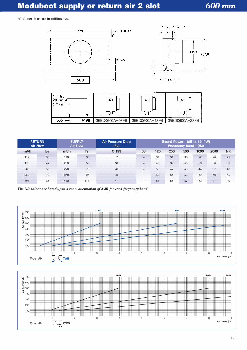
23
Moduboot supply or return air 2 slot
Type : AH
1 2 3 4 5 6 7 8 9Air throw (m)
min avg. max
100
200
300
400
500
600
700
Air
flo
w (m
3 /h)
TWB
Type : AH
1 2 3 4 5 6 7 8 9Air throw (m)
min avg. max
100
200
300
400
500
600
700
Air
flo
w (m
3 /h)
OWB
RETURNAir Flow
m3/h l/s m3/h l/s Ø 199 63 125 250 500 1000 2000 NR
SUPPLYAir Flow
Air Pressure Drop(Pa)
Sound Power – (dB at 10–12 W)Frequency Band – (Hz)
The NR values are based upon a room attenuation of 4 dB for each frequency band.
119 33 140 38 7 – 34 31 30 22 20 22
170 47 200 56 16 – 45 39 40 36 30 32
200 55 270 75 26 – 50 47 48 44 37 40
255 70 340 94 36 – 53 51 53 49 43 45
307 85 410 113 41 – 57 56 57 52 47 49
600 mm
35BD0600AH03FB 35BD0600AH13FB 35BD0600AH23FB
All dimensions are in millimetres.
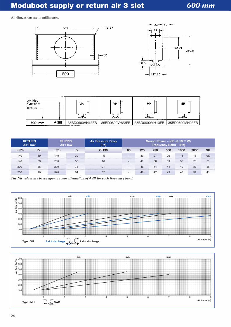
Type : VH 2 slot discharge
1 2 3 4 5 6 7 8 9Air throw (m)
min min avg. avg. max max
100
200
300
400
500
600
700
Air
flo
w (m
3 /h)
1 slot discharge
Moduboot supply or return air 3 slot
Type : MH OWB
1 2 3 4 5 6 7 8 9Air throw (m)
min avg. max
100
200
300
400
500
600
700
Air
flo
w (m
3 /h)
RETURNAir Flow
m3/h l/s m3/h l/s Ø 199 63 125 250 500 1000 2000 NR
SUPPLYAir Flow
Air Pressure Drop(Pa)
Sound Power – (dB at 10–12 W)Frequency Band – (Hz)
140 39 140 39 5 - 30 27 26 18 16 <20
140 39 200 55 10 - 41 38 39 35 26 31
200 55 270 75 21 - 46 44 44 40 33 36
250 70 340 94 32 - 49 47 49 45 39 41
The NR values are based upon a room attenuation of 4 dB for each frequency band.
600 mm
35BD0600VH13FB 35BD0600VH23FB 35BD0600MH13FB 35BD0600MH23FB
24
All dimensions are in millimetres.
25
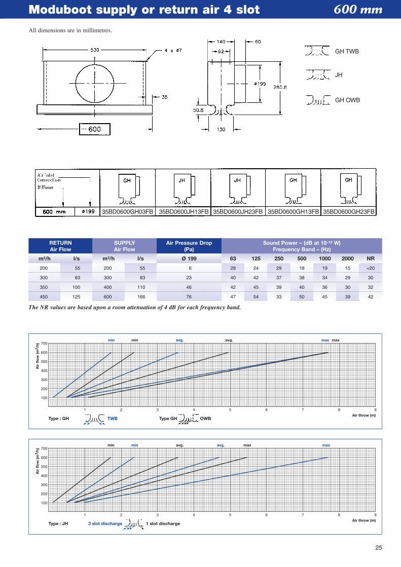
Moduboot supply or return air 4 slot
Type : JH 3 slot discharge 1 slot discharge
1 2 3 4 5 6 7 8 9Air throw (m)
min min avg. avg. max max
100
200
300
400
500
600
700
Air
flo
w (m
3 /h)
Type : GH TWB Type GH OWB
1 2 3 4 5 6 7 8 9Air throw (m)
min min avg. avg. max max
100
200
300
400
500
600
700
Air
flo
w (m
3 /h)
RETURNAir Flow
m3/h l/s m3/h l/s Ø 199 63 125 250 500 1000 2000 NR
SUPPLYAir Flow
Air Pressure Drop(Pa)
Sound Power – (dB at 10–12 W)Frequency Band – (Hz)
200 55 200 55 6 28 24 29 18 19 15 <20
300 83 300 83 23 40 42 37 38 34 29 30
350 100 400 110 46 42 45 39 40 36 30 32
450 125 600 166 76 47 54 33 50 45 39 42
The NR values are based upon a room attenuation of 4 dB for each frequency band.
600 mm
35BD0600GH03FB 35BD0600JH13FB 35BD0600JH23FB 35BD0600GH13FB 35BD0600GH23FB
All dimensions are in millimetres.
GH TWB
JH
GH OWB
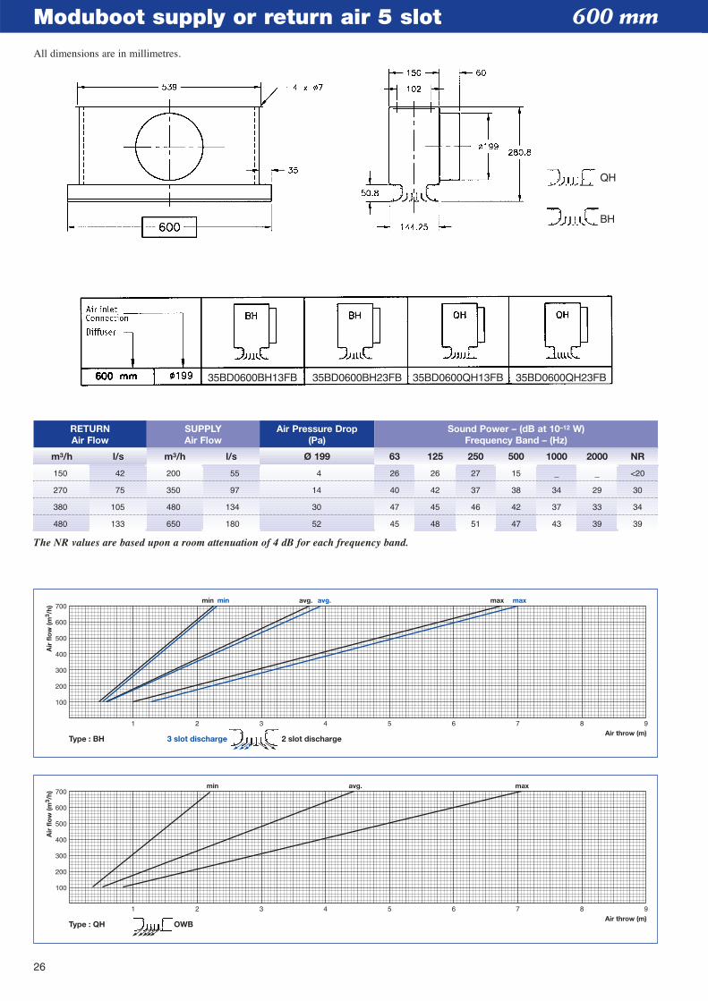
Moduboot supply or return air 5 slot
Type : QH OWB
1 2 3 4 5 6 7 8 9Air throw (m)
min avg. max
100
200
300
400
500
600
700
Air
flo
w (m
3 /h)
Type : BH 3 slot discharge 2 slot discharge
1 2 3 4 5 6 7 8 9Air throw (m)
min min avg. avg. max max
100
200
300
400
500
600
700
Air
flo
w (m
3 /h)
RETURNAir Flow
m3/h l/s m3/h l/s Ø 199 63 125 250 500 1000 2000 NR
SUPPLYAir Flow
Air Pressure Drop(Pa)
Sound Power – (dB at 10–12 W)Frequency Band – (Hz)
150 42 200 55 4 26 26 27 15 _ _ <20
270 75 350 97 14 40 42 37 38 34 29 30
380 105 480 134 30 47 45 46 42 37 33 34
480 133 650 180 52 45 48 51 47 43 39 39
The NR values are based upon a room attenuation of 4 dB for each frequency band.
600 mm
35BD0600BH13FB 35BD0600BH23FB 35BD0600QH13FB 35BD0600QH23FB
26
All dimensions are in millimetres.
QH
BH
27
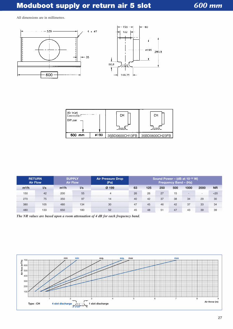
Moduboot supply or return air 5 slot
Type : CH
1 2 3 4 5 6 7 8 9Air throw (m)
min min avg. avg. max max
100
200
300
400
500
600
700
Air
flo
w (m
3 /h)
4 slot discharge 1 slot discharge
RETURNAir Flow
m3/h l/s m3/h l/s Ø 199 63 125 250 500 1000 2000 NR
SUPPLYAir Flow
Air Pressure Drop(Pa)
Sound Power – (dB at 10–12 W)Frequency Band – (Hz)
150 42 200 55 4 26 26 27 15 - - <20
270 75 350 97 14 40 42 37 38 34 29 30
380 105 480 134 30 47 45 46 42 37 33 34
480 133 650 180 52 45 48 51 47 43 39 39
The NR values are based upon a room attenuation of 4 dB for each frequency band.
600 mm
35BD0600CH13FB 35BD0600CH23FB
All dimensions are in millimetres.
28
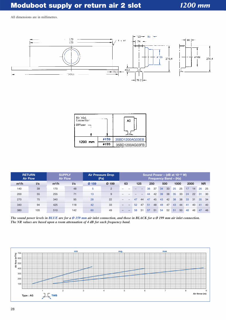
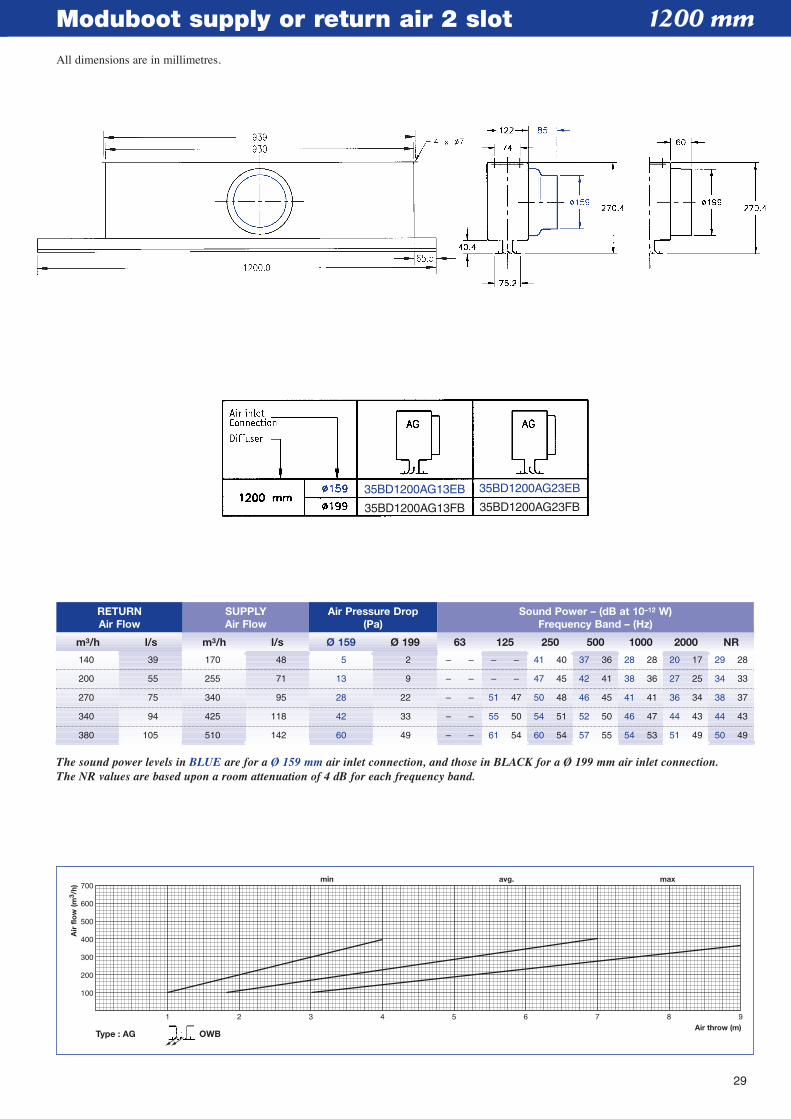
Moduboot supply or return air 2 slot
Type : AG
1 2 3 4 5 6 7 8 9Air throw (m)
min avg. max
100
200
300
400
500
600
700
Air
flo
w (m
3 /h)
TWB
RETURNAir Flow
m3/h l/s m3/h l/s Ø 159 Ø 199 63 125 250 500 1000 2000 NR
SUPPLYAir Flow
Air Pressure Drop(Pa)
Sound Power – (dB at 10–12 W)Frequency Band – (Hz)
The sound power levels in BLUE are for a Ø 159 mm air inlet connection, and those in BLACK for a Ø 199 mm air inlet connection.The NR values are based upon a room attenuation of 4 dB for each frequency band.
140 39 170 48 5 2 – – – – 38 37 34 33 25 25 17 14 26 25
200 55 255 71 13 9 – – – – 44 42 39 38 35 33 24 22 31 30
270 75 340 95 28 22 – – 47 44 47 45 43 42 38 38 33 31 35 34
340 94 425 118 42 33 – – 52 47 51 48 49 47 43 44 41 40 41 40
380 105 510 142 60 49 – – 58 51 57 51 54 52 51 50 48 46 47 46
1200 mm
35BD1200AG03EB
35BD1200AG03FB
All dimensions are in millimetres.
29
Moduboot supply or return air 2 slot
Type : AG OWB
1 2 3 4 5 6 7 8 9Air throw (m)
min avg. max
100
200
300
400
500
600
700
Air
flo
w (m
3 /h)
RETURNAir Flow
m3/h l/s m3/h l/s Ø 159 Ø 199 63 125 250 500 1000 2000 NR
SUPPLYAir Flow
Air Pressure Drop(Pa)
Sound Power – (dB at 10–12 W)Frequency Band – (Hz)
The sound power levels in BLUE are for a Ø 159 mm air inlet connection, and those in BLACK for a Ø 199 mm air inlet connection.The NR values are based upon a room attenuation of 4 dB for each frequency band.
140 39 170 48 5 2 – – – – 41 40 37 36 28 28 20 17 29 28
200 55 255 71 13 9 – – – – 47 45 42 41 38 36 27 25 34 33
270 75 340 95 28 22 – – 51 47 50 48 46 45 41 41 36 34 38 37
340 94 425 118 42 33 – – 55 50 54 51 52 50 46 47 44 43 44 43
380 105 510 142 60 49 – – 61 54 60 54 57 55 54 53 51 49 50 49
1200 mm
35BD1200AG13EB
35BD1200AG13FB
35BD1200AG23EB
35BD1200AG23FB
All dimensions are in millimetres.
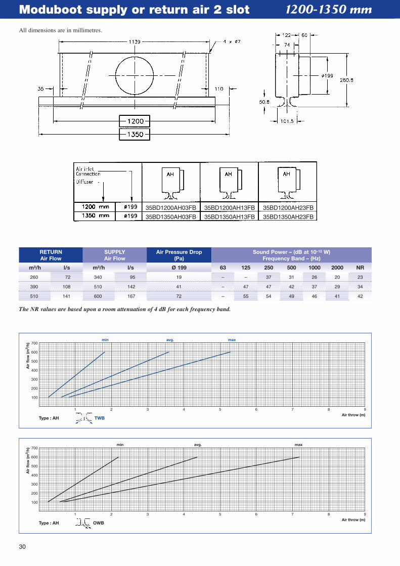
Moduboot supply or return air 2 slot
Type : AH OWB
1 2 3 4 5 6 7 8 9Air throw (m)
min avg. max
100
200
300
400
500
600
700
Air
flo
w (m
3 /h)
Type : AH
1 2 3 4 5 6 7 8 9Air throw (m)
min avg. max
100
200
300
400
500
600
700
Air
flo
w (m
3 /h)
TWB
RETURNAir Flow
m3/h l/s m3/h l/s Ø 199 63 125 250 500 1000 2000 NR
SUPPLYAir Flow
Air Pressure Drop(Pa)
Sound Power – (dB at 10–12 W)Frequency Band – (Hz)
The NR values are based upon a room attenuation of 4 dB for each frequency band.
260 72 340 95 19 – – 37 31 26 20 23
390 108 510 142 41 – 47 47 42 37 29 34
510 141 600 167 72 – 55 54 49 46 41 42
1200-1350 mm
35BD1200AH03FB
35BD1350AH03FB
35BD1200AH13FB
35BD1350AH13FB
35BD1200AH23FB
35BD1350AH23FB
30
All dimensions are in millimetres.
31
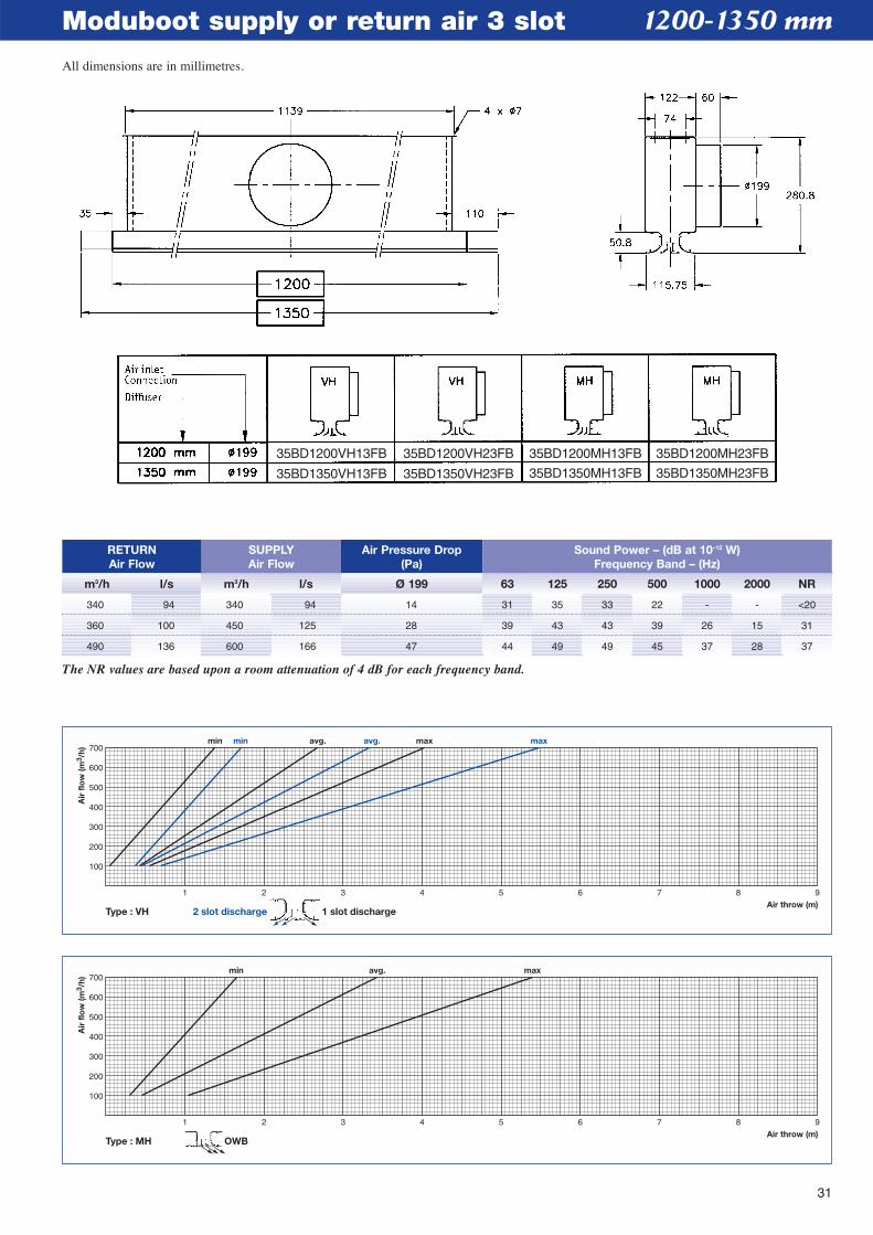
Moduboot supply or return air 3 slot
Type : MH OWB
1 2 3 4 5 6 7 8 9Air throw (m)
min avg. max
100
200
300
400
500
600
700
Air
flo
w (m
3 /h)
Type : VH
1 2 3 4 5 6 7 8 9Air throw (m)
min min avg. avg. max max
100
200
300
400
500
600
700
Air
flo
w (m
3 /h)
2 slot discharge 1 slot discharge
RETURNAir Flow
m3/h l/s m3/h l/s Ø 199 63 125 250 500 1000 2000 NR
SUPPLYAir Flow
Air Pressure Drop(Pa)
Sound Power – (dB at 10–12 W)Frequency Band – (Hz)
340 94 340 94 14 31 35 33 22 - - <20
360 100 450 125 28 39 43 43 39 26 15 31
490 136 600 166 47 44 49 49 45 37 28 37
The NR values are based upon a room attenuation of 4 dB for each frequency band.
1200-1350 mm
35BD1200VH13FB
35BD1350VH13FB
35BD1200VH23FB
35BD1350VH23FB
35BD1200MH13FB
35BD1350MH13FB
35BD1200MH23FB
35BD1350MH23FB
All dimensions are in millimetres.
32
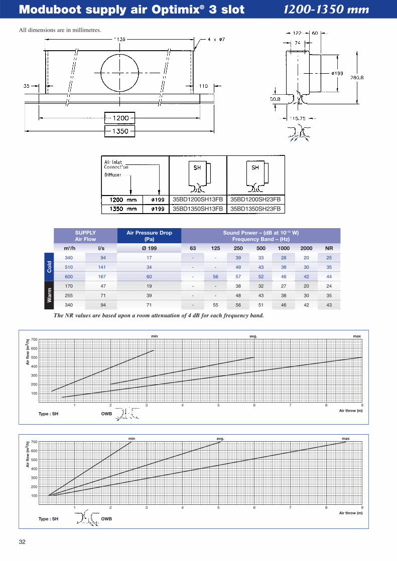
Moduboot supply air Optimix® 3 slot
Type : SH OWB
1 2 3 4 5 6 7 8 9Air throw (m)
min avg. max
100
200
300
400
500
600
700
Air
flo
w (m
3 /h)
1 2 3 4 5 6 7 8 9Air throw (m)
min avg. max
100
200
300
400
500
600
700
Air
flo
w (m
3 /h)
Type : SH OWB
1200-1350 mm
m3/h l/s Ø 199 63 125 250 500 1000 2000 NR
SUPPLYAir Flow
Air Pressure Drop(Pa)
Sound Power – (dB at 10–12 W)Frequency Band – (Hz)
340 94 17 - - 39 33 28 20 25
510 141 34 - - 49 43 38 30 35
600 167 60 - 56 57 52 46 42 44
170 47 19 - - 38 32 27 20 24
255 71 39 - - 48 43 38 30 35
340 94 71 - 55 56 51 46 42 43
The NR values are based upon a room attenuation of 4 dB for each frequency band.
Co
ldW
arm
35BD1200SH13FB
35BD1350SH13FB
35BD1200SH23FB
35BD1350SH23FB
All dimensions are in millimetres.
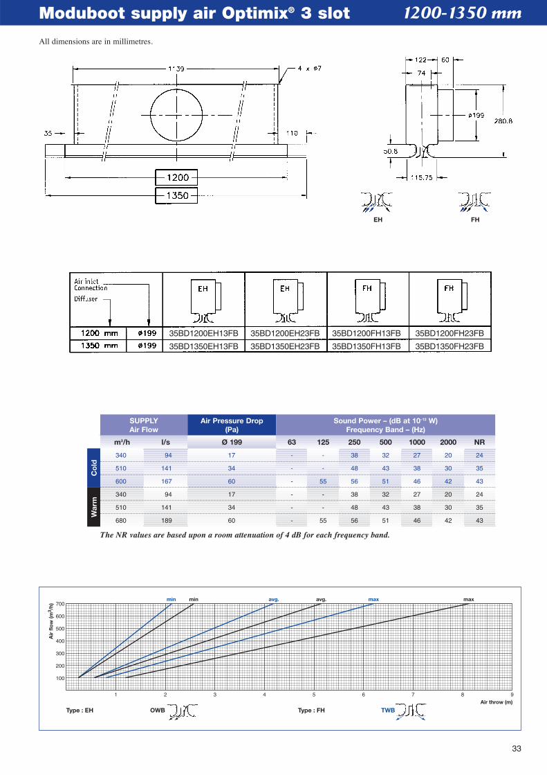
33
Moduboot supply air Optimix® 3 slot
1 2 3 4 5 6 7 8 9Air throw (m)
min avg. maxmin avg. max
100
200
300
400
500
600
700
Air
flo
w (m
3 /h)
Type : EH Type : FH TWBOWB
1200-1350 mm
m3/h l/s Ø 199 63 125 250 500 1000 2000 NR
SUPPLYAir Flow
Air Pressure Drop(Pa)
Sound Power – (dB at 10–12 W)Frequency Band – (Hz)
340 94 17 - - 38 32 27 20 24
510 141 34 - - 48 43 38 30 35
600 167 60 - 55 56 51 46 42 43
340 94 17 - - 38 32 27 20 24
510 141 34 - - 48 43 38 30 35
680 189 60 - 55 56 51 46 42 43
The NR values are based upon a room attenuation of 4 dB for each frequency band.
Co
ldW
arm
EH FH
35BD1200EH13FB
35BD1350EH13FB
35BD1200EH23FB
35BD1350EH23FB
35BD1200FH13FB
35BD1350FH13FB
35BD1200FH23FB
35BD1350FH23FB
All dimensions are in millimetres.
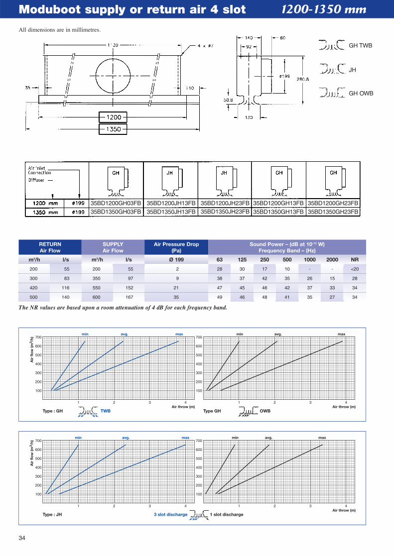
34
Moduboot supply or return air 4 slot
1 2 3 4Air throw (m)
100
200
300
400
500
600
700
100
200
300
400
500
600
700min avg. max
Air
flo
w (m
3 /h)
1 2 3 4
min avg. max
Type : JH 3 slot discharge 1 slot discharge
1 2 3 4Air throw (m)Air throw (m)
100
200
300
400
500
600
700
100
200
300
400
500
600
700min avg. max
Air
flo
w (m
3 /h)
1 2 3 4
min avg. max
Type : GH Type GHTWB OWB
1200-1350 mm
RETURNAir Flow
m3/h l/s m3/h l/s Ø 199 63 125 250 500 1000 2000 NR
SUPPLYAir Flow
Air Pressure Drop(Pa)
Sound Power – (dB at 10–12 W)Frequency Band – (Hz)
200 55 200 55 2 28 30 17 10 - - <20
300 83 350 97 9 38 37 42 35 26 15 28
420 116 550 152 21 47 45 46 42 37 33 34
500 140 600 167 35 49 46 48 41 35 27 34
The NR values are based upon a room attenuation of 4 dB for each frequency band.
35BD1200GH03FB35BD1350GH03FB
35BD1200JH13FB
35BD1350JH13FB
35BD1200JH23FB35BD1350JH23FB
35BD1200GH13FB
35BD1350GH13FB
35BD1200GH23FB
35BD1350GH23FB
All dimensions are in millimetres.
GH TWB
JH
GH OWB
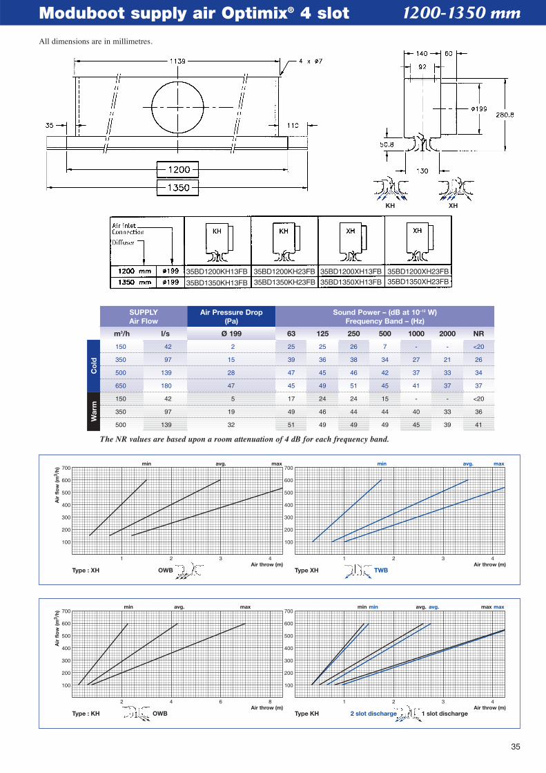
35
Moduboot supply air Optimix® 4 slot
2 4 6 8Air throw (m)Air throw (m)
100
200
300
400
500
600
700
100
200
300
400
500
600
700min avg. max
Air
flo
w (m
3 /h)
1 2 3 4
min avg. maxmin avg. max
Type : KH Type KH 1 slot discharge2 slot dischargeOWB
1 2 3 4Air throw (m)Air throw (m)
100
200
300
400
500
600
700
100
200
300
400
500
600
700min avg. max
Air
flo
w (m
3 /h)
1 2 3 4
min avg. max
Type : XH Type XH TWBOWB
1200-1350 mm
m3/h l/s Ø 199 63 125 250 500 1000 2000 NR
SUPPLYAir Flow
Air Pressure Drop(Pa)
Sound Power – (dB at 10–12 W)Frequency Band – (Hz)
150 42 2 25 25 26 7 - - <20
350 97 15 39 36 38 34 27 21 26
500 139 28 47 45 46 42 37 33 34
650 180 47 45 49 51 45 41 37 37
150 42 5 17 24 24 15 - - <20
350 97 19 49 46 44 44 40 33 36
500 139 32 51 49 49 49 45 39 41
The NR values are based upon a room attenuation of 4 dB for each frequency band.
Co
ldW
arm
KH XH
35BD1200KH13FB
35BD1350KH13FB
35BD1200KH23FB
35BD1350KH23FB
35BD1200XH13FB35BD1350XH13FB
35BD1200XH23FB35BD1350XH23FB
All dimensions are in millimetres.
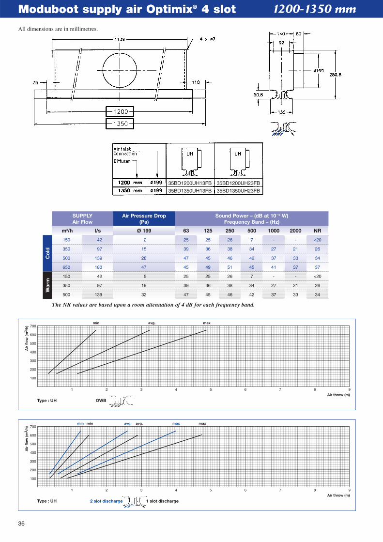
36
Moduboot supply air Optimix® 4 slot 1200-1350 mm
Type : UH
1 2 3 4 5 6 7 8 9Air throw (m)
min avg. maxmin avg. max
100
200
300
400
500
600
700
Air
flo
w (m
3 /h)
1 slot discharge2 slot discharge
Type : UH OWB
1 2 3 4 5 6 7 8 9Air throw (m)
min avg. max
100
200
300
400
500
600
700
Air
flo
w (m
3 /h)
m3/h l/s Ø 199 63 125 250 500 1000 2000 NR
SUPPLYAir Flow
Air Pressure Drop(Pa)
Sound Power – (dB at 10–12 W)Frequency Band – (Hz)
150 42 2 25 25 26 7 - - <20
350 97 15 39 36 38 34 27 21 26
500 139 28 47 45 46 42 37 33 34
650 180 47 45 49 51 45 41 37 37
150 42 5 25 25 26 7 - - <20
350 97 19 39 36 38 34 27 21 26
500 139 32 47 45 46 42 37 33 34
The NR values are based upon a room attenuation of 4 dB for each frequency band.
Co
ldW
arm
35BD1200UH13FB 35BD1200UH23FB
35BD1350UH13FB 35BD1350UH23FB
All dimensions are in millimetres.
37
Moduboot supply or return air 5 slot
Type : QH OWB
0.5 1 1.5 2 2.5 3 3.5 4 4.5Air throw (m)
min avg. max
100
200
300
400
500
600
700
Air
flo
w (m
3 /h)
1 2 3 4Air throw (m)
100
200
300
400
500
600
700
100
200
300
400
500
600
700min avg. max
Air
flo
w (m
3 /h)
1 2 3 4
min avg. max
Type : BH 3 slot discharge 2 slot discharge
1200-1350 mm
RETURNAir Flow
m3/h l/s m3/h l/s Ø 199 63 125 250 500 1000 2000 NR
SUPPLYAir Flow
Air Pressure Drop(Pa)
Sound Power – (dB at 10–12 W)Frequency Band – (Hz)
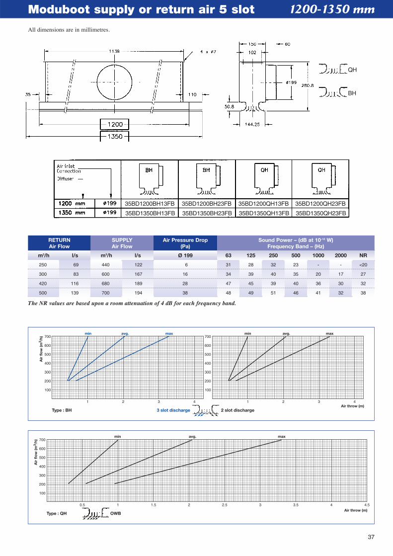
250 69 440 122 6 31 28 32 23 - - <20
300 83 600 167 16 34 39 40 35 20 17 27
420 116 680 189 28 47 45 39 40 36 30 32
500 139 700 194 38 48 49 51 46 41 32 38
The NR values are based upon a room attenuation of 4 dB for each frequency band.
35BD1200BH13FB
35BD1350BH13FB
35BD1200BH23FB
35BD1350BH23FB
35BD1200QH13FB
35BD1350QH13FB
35BD1200QH23FB
35BD1350QH23FB
All dimensions are in millimetres.
QH
BH
38
Moduboot supply or return air 5 slot
1 2 3 4Air throw (m)
100
200
300
400
500
600
700
100
200
300
400
500
600
700min avg. max
Air
flo
w (m
3 /h)
1 2 3 4
min avg. max
Type : CH 4 slot discharge 1 slot discharge
RETURNAir Flow
m3/h l/s m3/h l/s Ø 199 63 125 250 500 1000 2000 NR
SUPPLYAir Flow
Air Pressure Drop(Pa)
Sound Power – (dB at 10–12 W)Frequency Band – (Hz)
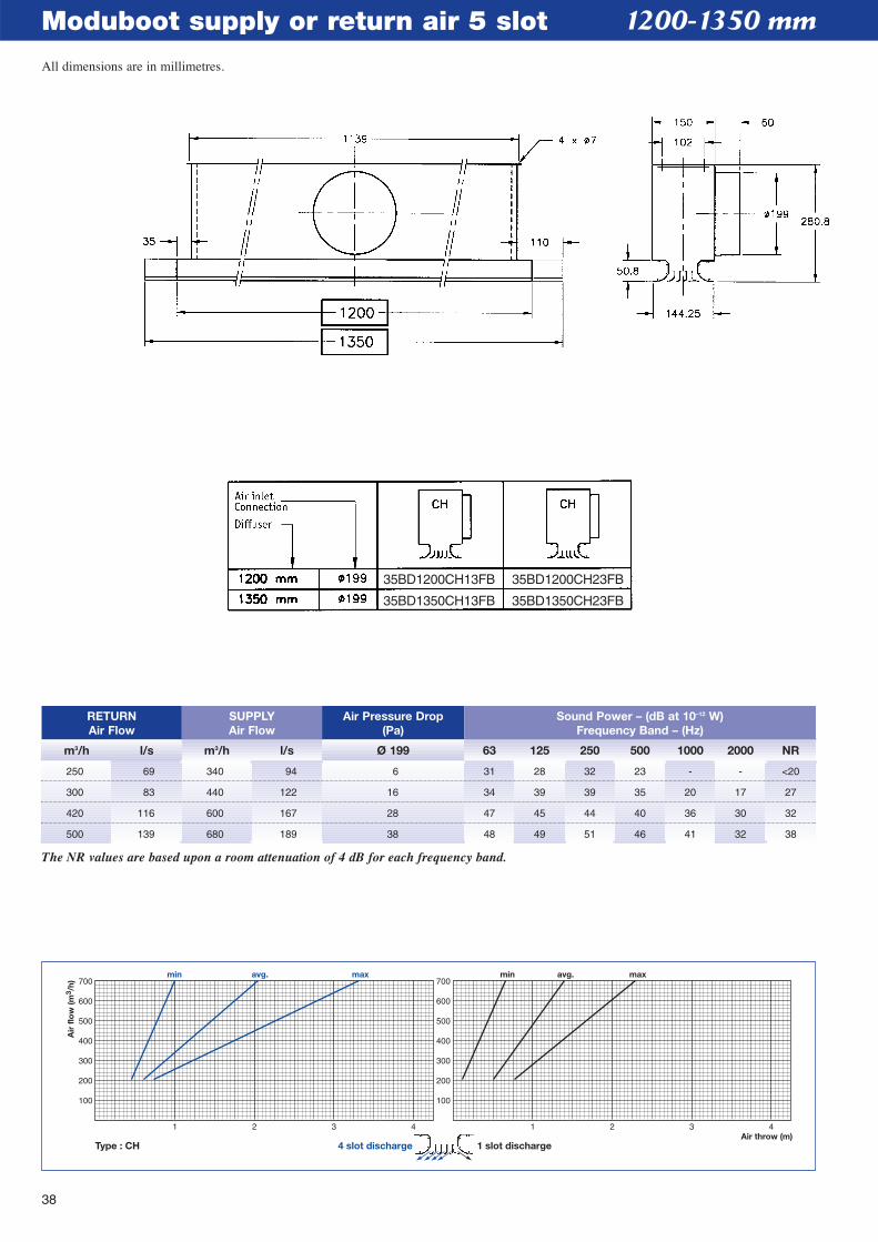
250 69 340 94 6 31 28 32 23 - - <20
300 83 440 122 16 34 39 39 35 20 17 27
420 116 600 167 28 47 45 44 40 36 30 32
500 139 680 189 38 48 49 51 46 41 32 38
The NR values are based upon a room attenuation of 4 dB for each frequency band.
1200-1350 mm
35BD1200CH13FB
35BD1350CH13FB
35BD1200CH23FB
35BD1350CH23FB
All dimensions are in millimetres.
39
Moduboot supply air Optimix® 5 slot
1 2 3 4Air throw (m)Air throw (m)
100
200
300
400
500
600
700
100
200
300
400
500
600
700min avg. max
Air
flo
w (m
3 /h)
1 2 3 4
min avg. maxmin avg. max
Type : NH Type NH 2 slot discharge1 slot dischargeOWB
1 2 3 4Air throw (m)Air throw (m)
100
200
300
400
500
600
700
100
200
300
400
500
600
700min avg. max
Air
flo
w (m
3 /h)
1 2 3 4
min avg. max
Type : LH Type LH TWBOWB
1200-1350 mm
m3/h l/s Ø 199 63 125 250 500 1000 2000 NR
SUPPLYAir Flow
Air Pressure Drop(Pa)
Sound Power – (dB at 10–12 W)Frequency Band – (Hz)
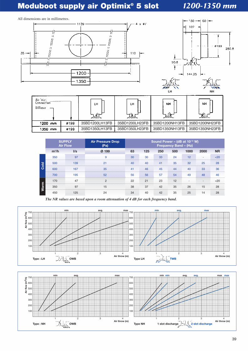
350 97 9 30 30 33 24 12 - <20
500 139 21 40 40 41 35 32 25 28
600 167 35 41 46 45 44 40 33 36
700 195 52 56 56 57 54 49 48 46
170 47 2 22 21 23 12 - - <20
350 97 15 38 37 42 35 26 15 28
450 125 24 34 40 42 35 25 14 28
The NR values are based upon a room attenuation of 4 dB for each frequency band.
Co
ldW
arm
LH NH
35BD1200LH13FB
35BD1350LH13FB
35BD1200LH23FB
35BD1350LH23FB
35BD1200NH13FB
35BD1350NH13FB
35BD1200NH23FB
35BD1350NH23FB
All dimensions are in millimetres.
40
Moduboot supply or return air 2 slot
Type : AG OWB
1 2 3 4 5 6 7 8 9Air throw (m)
min avg. max
100
200
300
400
500
600
700
Air
flo
w (m
3 /h)
RETURNAir Flow
m3/h l/s m3/h l/s Ø 159 Ø 199 63 125 250 500 1000 2000 NR
SUPPLYAir Flow
Air Pressure Drop(Pa)
Sound Power – (dB at 10–12 W)Frequency Band – (Hz)
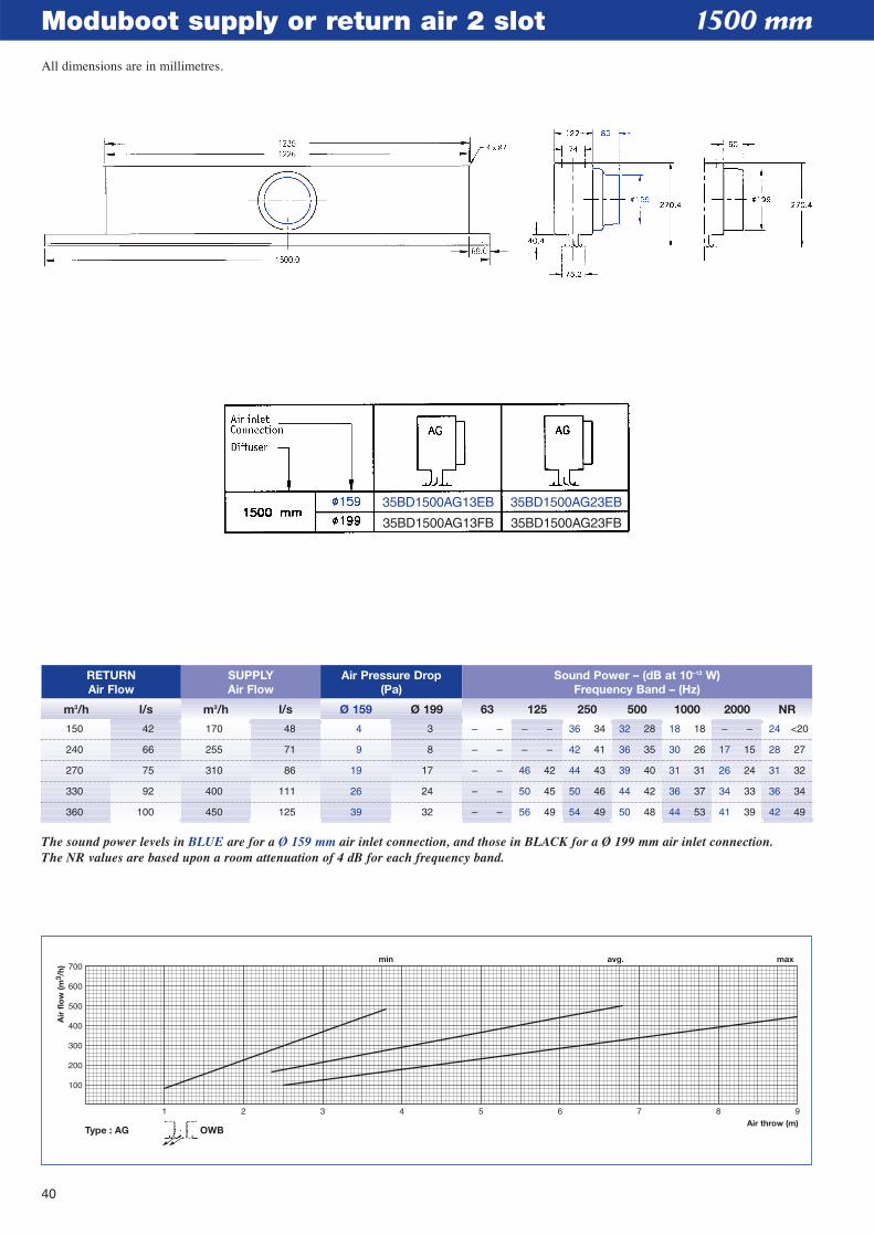
The sound power levels in BLUE are for a Ø 159 mm air inlet connection, and those in BLACK for a Ø 199 mm air inlet connection.The NR values are based upon a room attenuation of 4 dB for each frequency band.
150 42 170 48 4 3 – – – – 36 34 32 28 18 18 – – 24 <20
240 66 255 71 9 8 – – – – 42 41 36 35 30 26 17 15 28 27
270 75 310 86 19 17 – – 46 42 44 43 39 40 31 31 26 24 31 32
330 92 400 111 26 24 – – 50 45 50 46 44 42 36 37 34 33 36 34
360 100 450 125 39 32 – – 56 49 54 49 50 48 44 53 41 39 42 49
1500 mm
35BD1500AG13EB
35BD1500AG13FB
35BD1500AG23EB
35BD1500AG23FB
All dimensions are in millimetres.
41
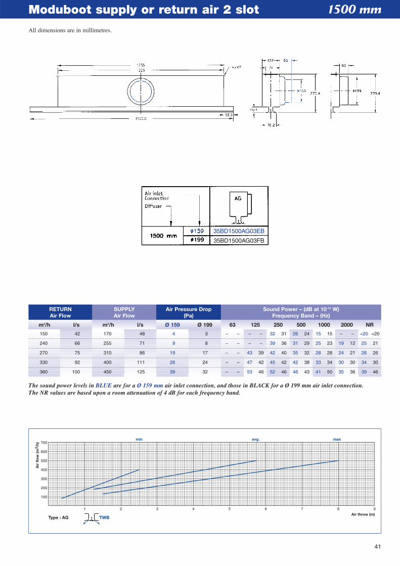
Moduboot supply or return air 2 slot
Type : AG TWB
1 2 3 4 5 6 7 8 9Air throw (m)
min avg. max
100
200
300
400
500
600
700
Air
flo
w (m
3 /h)
RETURNAir Flow
m3/h l/s m3/h l/s Ø 159 Ø 199 63 125 250 500 1000 2000 NR
SUPPLYAir Flow
Air Pressure Drop(Pa)
Sound Power – (dB at 10–12 W)Frequency Band – (Hz)
The sound power levels in BLUE are for a Ø 159 mm air inlet connection, and those in BLACK for a Ø 199 mm air inlet connection.The NR values are based upon a room attenuation of 4 dB for each frequency band.
150 42 170 48 4 3 – – – – 32 31 26 24 15 15 – – <20 <20
240 66 255 71 9 8 – – – – 39 36 31 29 25 23 19 12 25 21
270 75 310 86 19 17 – – 43 39 42 40 35 32 28 28 24 21 28 26
330 92 400 111 26 24 – – 47 42 45 42 42 38 33 34 30 30 34 30
360 100 450 125 39 32 – – 53 46 52 46 46 43 41 50 35 36 39 46
1500 mm
35BD1500AG03EB
35BD1500AG03FB
All dimensions are in millimetres.
42
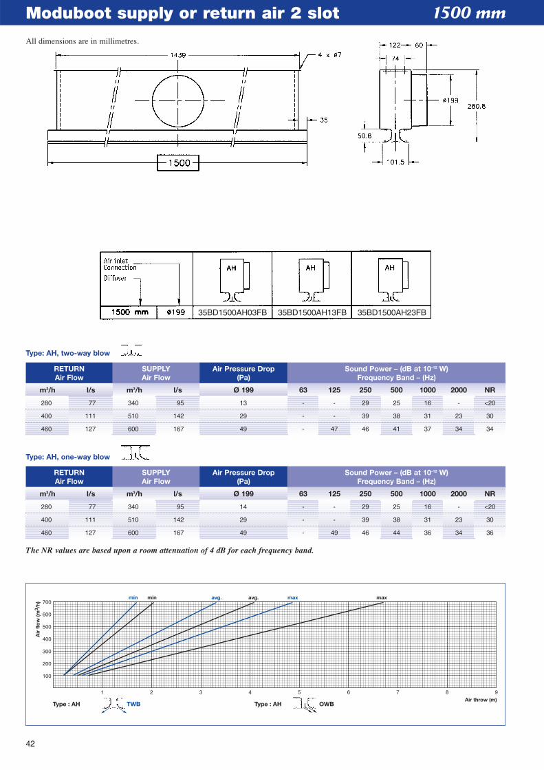
Moduboot supply or return air 2 slot
Type : AH TWB
1 2 3 4 5 6 7 8 9Air throw (m)
min avg. maxmin avg. max
100
200
300
400
500
600
700
Air
flo
w (m
3 /h)
Type : AH OWB
RETURNAir Flow
m3/h l/s m3/h l/s Ø 199 63 125 250 500 1000 2000 NR
SUPPLYAir Flow
Air Pressure Drop(Pa)
Sound Power – (dB at 10–12 W)Frequency Band – (Hz)
The NR values are based upon a room attenuation of 4 dB for each frequency band.
280 77 340 95 14 - - 29 25 16 - <20
400 111 510 142 29 - - 39 38 31 23 30
460 127 600 167 49 - 49 46 44 36 34 36
RETURNAir Flow
m3/h l/s m3/h l/s Ø 199 63 125 250 500 1000 2000 NR
SUPPLYAir Flow
Air Pressure Drop(Pa)
Sound Power – (dB at 10–12 W)Frequency Band – (Hz)
Type: AH, two-way blow
Type: AH, one-way blow
280 77 340 95 13 - - 29 25 16 - <20
400 111 510 142 29 - - 39 38 31 23 30
460 127 600 167 49 - 47 46 41 37 34 34
1500 mm
35BD1500AH03FB 35BD1500AH13FB 35BD1500AH23FB
All dimensions are in millimetres.
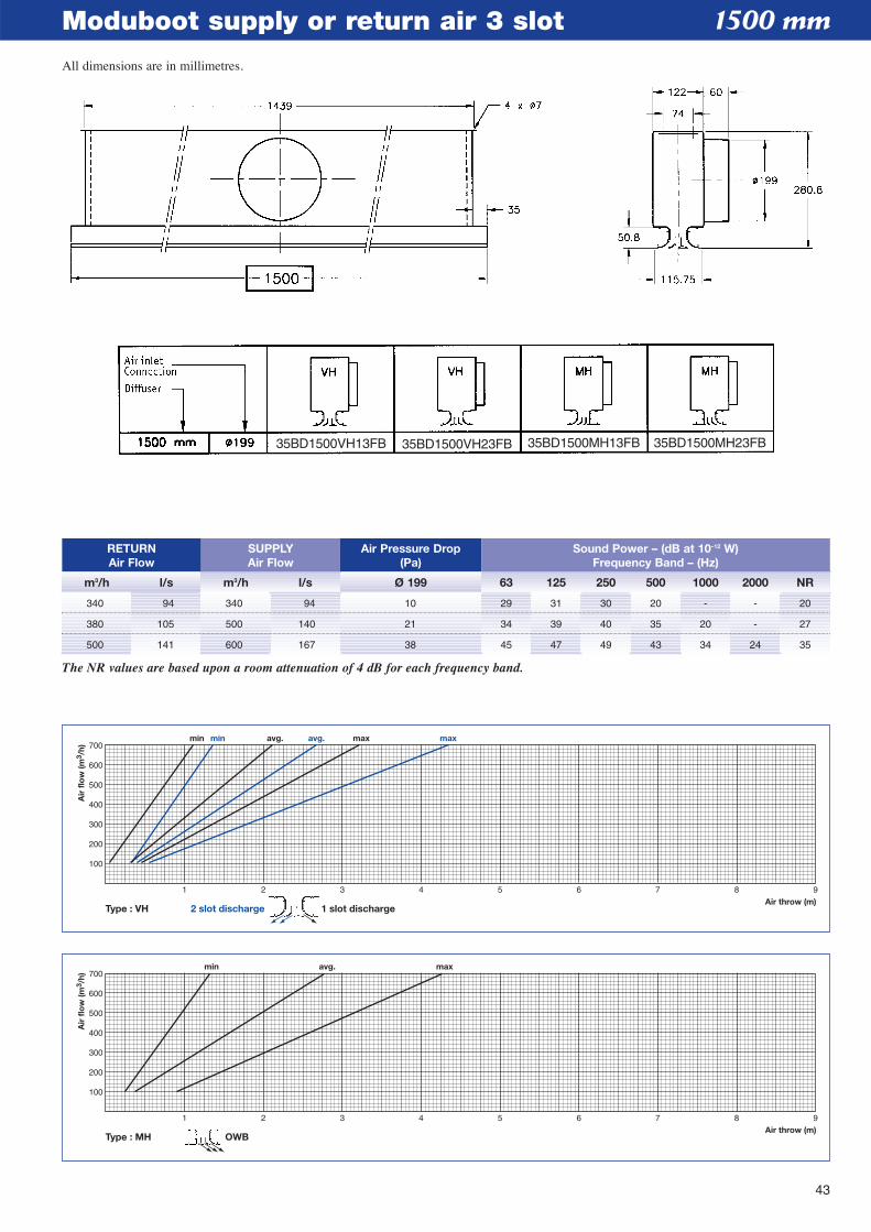
43
Moduboot supply or return air 3 slot
1 2 3 4 5 6 7 8 9Air throw (m)
min min avg. avg. max max
100
200
300
400
500
600
700
Air
flo
w (m
3 /h)
Type : VH 2 slot discharge 1 slot discharge
Type : MH OWB
1 2 3 4 5 6 7 8 9Air throw (m)
min avg. max
100
200
300
400
500
600
700
Air
flo
w (m
3 /h)
RETURNAir Flow
m3/h l/s m3/h l/s Ø 199 63 125 250 500 1000 2000 NR
SUPPLYAir Flow
Air Pressure Drop(Pa)
Sound Power – (dB at 10–12 W)Frequency Band – (Hz)
340 94 340 94 10 29 31 30 20 - - 20
380 105 500 140 21 34 39 40 35 20 - 27
500 141 600 167 38 45 47 49 43 34 24 35
The NR values are based upon a room attenuation of 4 dB for each frequency band.
1500 mm
35BD1500VH13FB 35BD1500VH23FB 35BD1500MH13FB 35BD1500MH23FB
All dimensions are in millimetres.
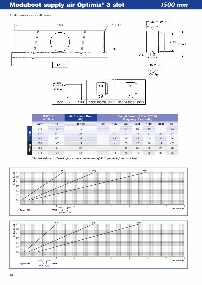
44
Moduboot supply air Optimix® 3 slot
1 2 3 4 5 6 7 8 9Air throw (m)
min avg. max
100
200
300
400
500
600
700
Air
flo
w (m
3 /h)
Type : SH OWB
1 2 3 4 5 6 7 8 9Air throw (m)
min avg. max
100
200
300
400
500
600
700
Air
flo
w (m
3 /h)
Type : SH OWB
1500 mm
m3/h l/s Ø 199 63 125 250 500 1000 2000 NR
SUPPLYAir Flow
Air Pressure Drop(Pa)
Sound Power – (dB at 10–12 W)Frequency Band – (Hz)
340 94 12 - - 31 28 19 - <20
510 141 24 - 47 47 42 37 29 34
600 167 38 - 49 49 43 40 36 36
170 47 14 - - 30 26 18 14 <20
255 71 29 - - 40 35 32 25 28
340 94 51 - 48 48 42 39 36 35
The NR values are based upon a room attenuation of 4 dB for each frequency band.
Co
ldW
arm
35BD1500SH13FB 35BD1500SH23FB
All dimensions are in millimetres.
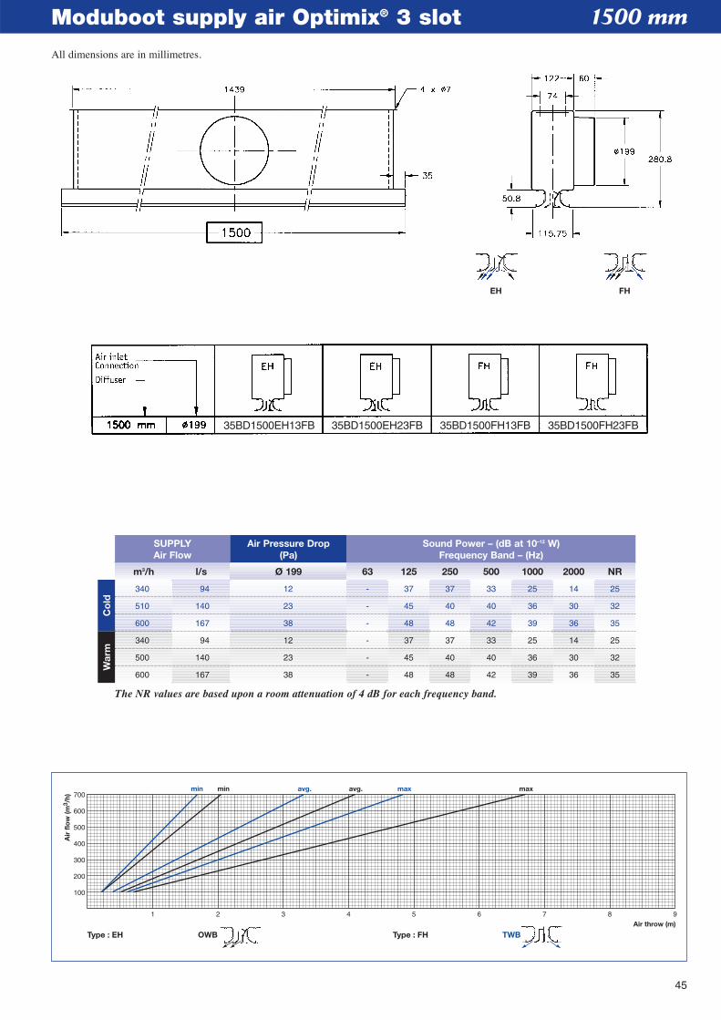
45
Moduboot supply air Optimix® 3 slot
1 2 3 4 5 6 7 8 9Air throw (m)
min avg. maxmin avg. max
100
200
300
400
500
600
700
Air
flo
w (m
3 /h)
Type : EH Type : FH TWBOWB
1500 mm
m3/h l/s Ø 199 63 125 250 500 1000 2000 NR
SUPPLYAir Flow
Air Pressure Drop(Pa)
Sound Power – (dB at 10–12 W)Frequency Band – (Hz)
340 94 12 - 37 37 33 25 14 25
510 140 23 - 45 40 40 36 30 32
600 167 38 - 48 48 42 39 36 35
340 94 12 - 37 37 33 25 14 25
500 140 23 - 45 40 40 36 30 32
600 167 38 - 48 48 42 39 36 35
The NR values are based upon a room attenuation of 4 dB for each frequency band.
Co
ldW
arm
EH FH
35BD1500EH13FB 35BD1500EH23FB 35BD1500FH13FB 35BD1500FH23FB
All dimensions are in millimetres.
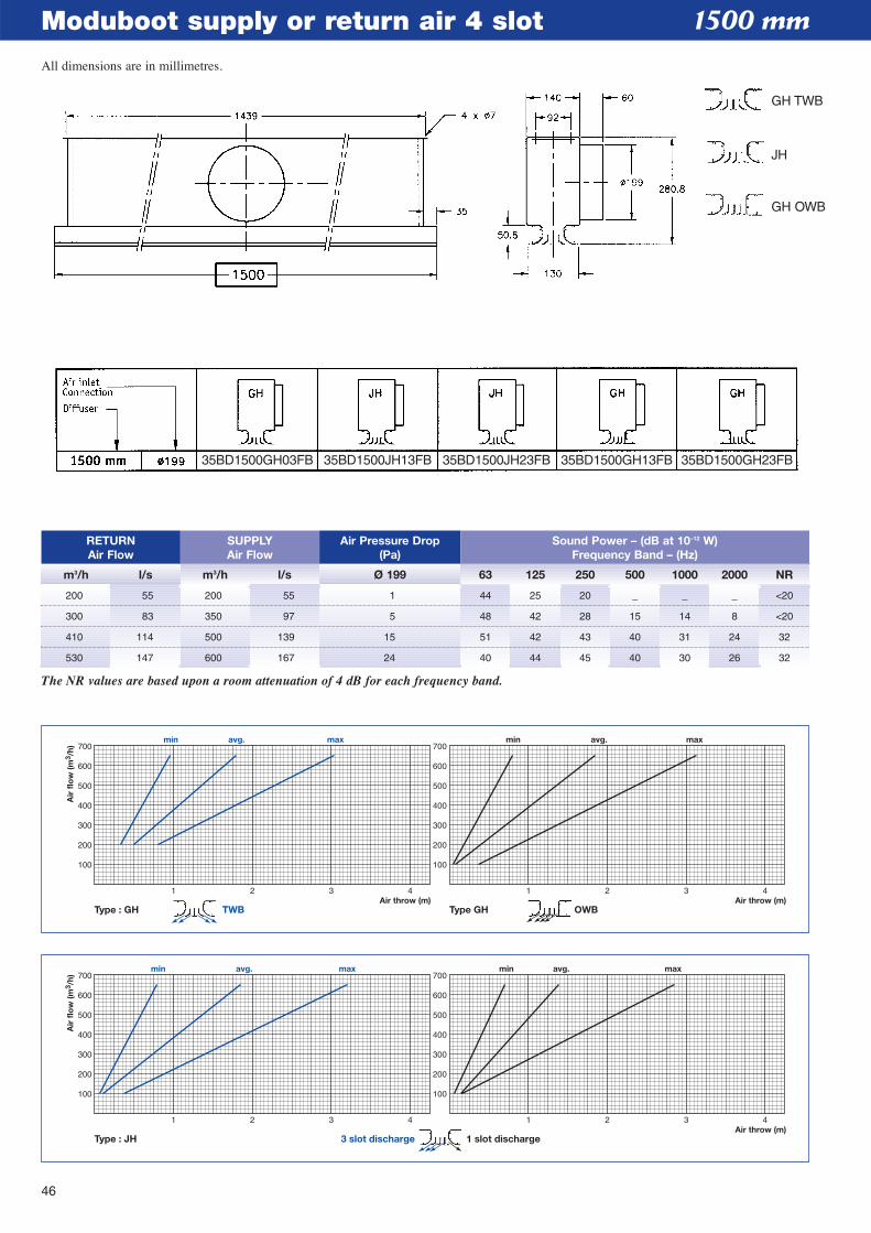
46
Moduboot supply or return air 4 slot
1 2 3 4Air throw (m)
100
200
300
400
500
600
700
100
200
300
400
500
600
700min avg. max
Air
flo
w (m
3 /h)
1 2 3 4
min avg. max
Type : JH 3 slot discharge 1 slot discharge
1 2 3 4Air throw (m)Air throw (m)
100
200
300
400
500
600
700
100
200
300
400
500
600
700min avg. max
Air
flo
w (m
3 /h)
1 2 3 4
min avg. max
Type : GH Type GHTWB OWB
1500 mm
RETURNAir Flow
m3/h l/s m3/h l/s Ø 199 63 125 250 500 1000 2000 NR
SUPPLYAir Flow
Air Pressure Drop(Pa)
Sound Power – (dB at 10–12 W)Frequency Band – (Hz)
200 55 200 55 1 44 25 20 _ _ _ <20
300 83 350 97 5 48 42 28 15 14 8 <20
410 114 500 139 15 51 42 43 40 31 24 32
530 147 600 167 24 40 44 45 40 30 26 32
The NR values are based upon a room attenuation of 4 dB for each frequency band.
35BD1500GH03FB 35BD1500JH13FB 35BD1500JH23FB 35BD1500GH13FB 35BD1500GH23FB
All dimensions are in millimetres.
GH TWB
JH
GH OWB
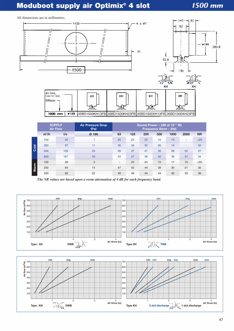
47
Moduboot supply air Optimix® 4 slot
1 2 3 4Air throw (m)Air throw (m)
100
200
300
400
500
600
700
100
200
300
400
500
600
700min avg. max
Air
flo
w (m
3 /h)
1 2 3 4
min avg. maxmin avg. max
Type : KH Type KH 1 slot discharge2 slot dischargeOWB
1 2 3 4Air throw (m)Air throw (m)
100
200
300
400
500
600
700
100
200
300
400
500
600
700min avg. max
Air
flo
w (m
3 /h)
1 2 3 4
min avg. max
Type : XH Type XH TWBOWB
1500 mm
m3/h l/s Ø 199 63 125 250 500 1000 2000 NR
SUPPLYAir Flow
Air Pressure Drop(Pa)
Sound Power – (dB at 10–12 W)Frequency Band – (Hz)
150 42 1 20 24 22 12 14 - <20
350 97 11 35 34 35 26 14 - 20
500 139 20 39 37 41 35 28 22 27
600 167 33 43 47 48 42 36 31 34
100 28 2 - 24 24 15 17 10 <20
230 64 14 47 42 44 38 30 21 30
330 92 22 49 46 44 44 40 33 36
The NR values are based upon a room attenuation of 4 dB for each frequency band.
Co
ldW
arm
KH XH
35BD1500KH13FB 35BD1500KH23FB 35BD1500XH13FB 35BD1500XH23FB
All dimensions are in millimetres.
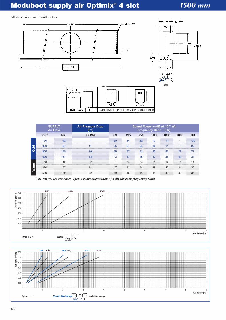
48
Moduboot supply air Optimix® 4 slot
1 2 3 4 5 6 7 8 9Air throw (m)
min avg. maxmin avg. max
100
200
300
400
500
600
700
Air
flo
w (m
3 /h)
Type : UH 1 slot discharge2 slot discharge
1 2 3 4 5 6 7 8 9Air throw (m)
min avg. max
100
200
300
400
500
600
700
Air
flo
w (m
3 /h)
Type : UH OWB
1500 mm
m3/h l/s Ø 199 63 125 250 500 1000 2000 NR
SUPPLYAir Flow
Air Pressure Drop(Pa)
Sound Power – (dB at 10–12 W)Frequency Band – (Hz)
150 42 1 20 24 22 12 14 - <20
350 97 11 35 34 35 26 14 - 20
500 139 20 39 37 41 35 28 22 27
600 167 33 43 47 48 42 36 31 34
150 42 2 - 24 24 15 17 10 14
350 97 14 47 42 44 38 30 21 30
500 139 22 49 46 44 44 40 33 36
The NR values are based upon a room attenuation of 4 dB for each frequency band.
Co
ldW
arm
UH
35BD1500UH13FB 35BD1500UH23FB
All dimensions are in millimetres.
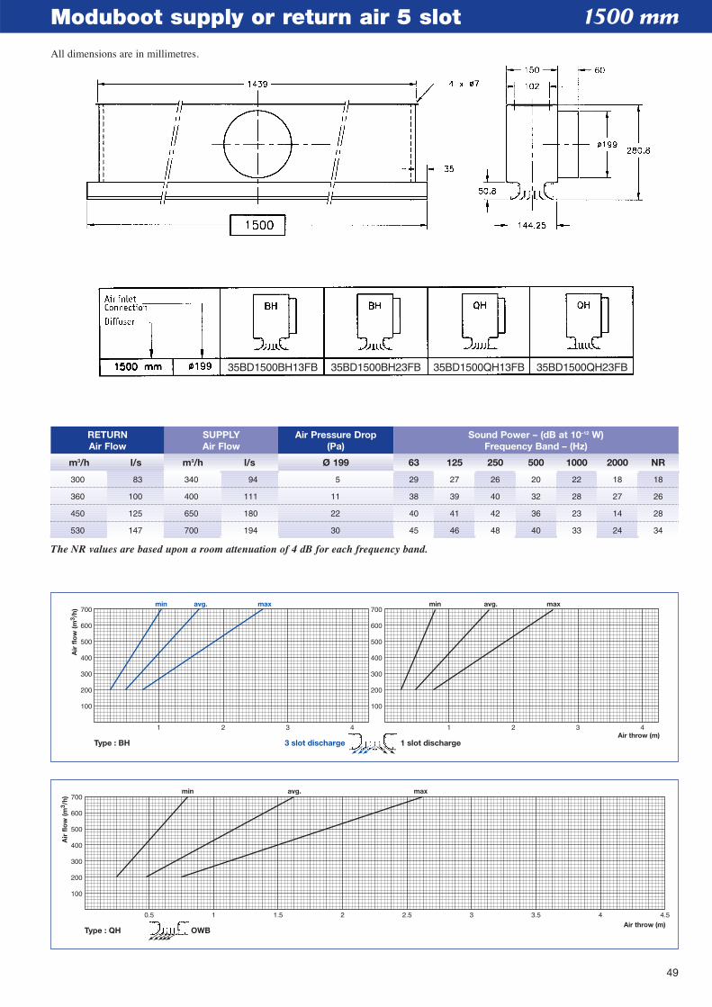
49
Moduboot supply or return air 5 slot
Type : QH OWB
0.5 1 1.5 2 2.5 3 3.5 4 4.5Air throw (m)
min avg. max
100
200
300
400
500
600
700
Air
flo
w (m
3 /h)
1 2 3 4Air throw (m)
100
200
300
400
500
600
700
100
200
300
400
500
600
700min avg. max
Air
flo
w (m
3 /h)
1 2 3 4
min avg. max
Type : BH 3 slot discharge 1 slot discharge
1500 mm
RETURNAir Flow
m3/h l/s m3/h l/s Ø 199 63 125 250 500 1000 2000 NR
SUPPLYAir Flow
Air Pressure Drop(Pa)
Sound Power – (dB at 10–12 W)Frequency Band – (Hz)
300 83 340 94 5 29 27 26 20 22 18 18
360 100 400 111 11 38 39 40 32 28 27 26
450 125 650 180 22 40 41 42 36 23 14 28
530 147 700 194 30 45 46 48 40 33 24 34
The NR values are based upon a room attenuation of 4 dB for each frequency band.
35BD1500BH13FB 35BD1500BH23FB 35BD1500QH13FB 35BD1500QH23FB
All dimensions are in millimetres.
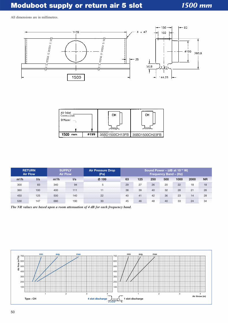
50
Moduboot supply or return air 5 slot
1 2 3 4Air throw (m)
100
200
300
400
500
600
700
100
200
300
400
500
600
700min avg. max
Air
flo
w (m
3 /h)
1 2 3 4
min avg. max
Type : CH 4 slot discharge 1 slot discharge
RETURNAir Flow
m3/h l/s m3/h l/s Ø 199 63 125 250 500 1000 2000 NR
SUPPLYAir Flow
Air Pressure Drop(Pa)
Sound Power – (dB at 10–12 W)Frequency Band – (Hz)
300 83 340 94 5 29 27 26 20 22 18 18
360 100 400 111 11 38 39 40 32 28 21 26
450 125 500 140 22 40 41 42 36 23 14 28
530 147 680 190 30 45 46 48 40 33 24 34
The NR values are based upon a room attenuation of 4 dB for each frequency band.
1500 mm
35BD1500CH13FB 35BD1500CH23FB
All dimensions are in millimetres.
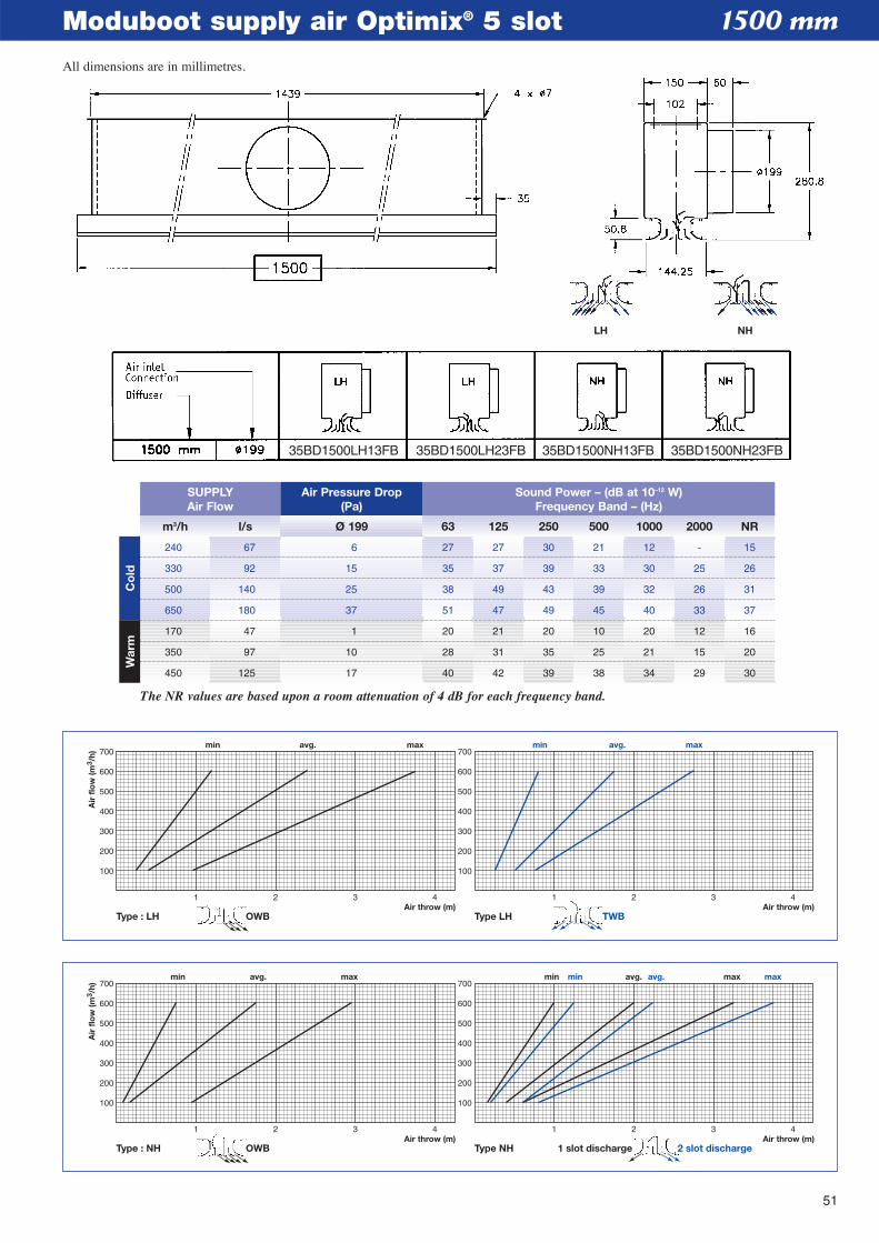
51
Moduboot supply air Optimix® 5 slot
1 2 3 4Air throw (m)Air throw (m)
100
200
300
400
500
600
700
100
200
300
400
500
600
700min avg. max
Air
flo
w (m
3 /h)
1 2 3 4
min avg. maxmin avg. max
Type : NH Type NH 2 slot discharge1 slot dischargeOWB
1 2 3 4Air throw (m)Air throw (m)
100
200
300
400
500
600
700
100
200
300
400
500
600
700min avg. max
Air
flo
w (m
3 /h)
1 2 3 4
min avg. max
Type : LH Type LH TWBOWB
1500 mm
m3/h l/s Ø 199 63 125 250 500 1000 2000 NR
SUPPLYAir Flow
Air Pressure Drop(Pa)
Sound Power – (dB at 10–12 W)Frequency Band – (Hz)
240 67 6 27 27 30 21 12 - 15
330 92 15 35 37 39 33 30 25 26
500 140 25 38 49 43 39 32 26 31
650 180 37 51 47 49 45 40 33 37
170 47 1 20 21 20 10 20 12 16
350 97 10 28 31 35 25 21 15 20
450 125 17 40 42 39 38 34 29 30
The NR values are based upon a room attenuation of 4 dB for each frequency band.
Co
ldW
arm
LH NH
35BD1500LH13FB 35BD1500LH23FB 35BD1500NH13FB 35BD1500NH23FB
All dimensions are in millimetres.
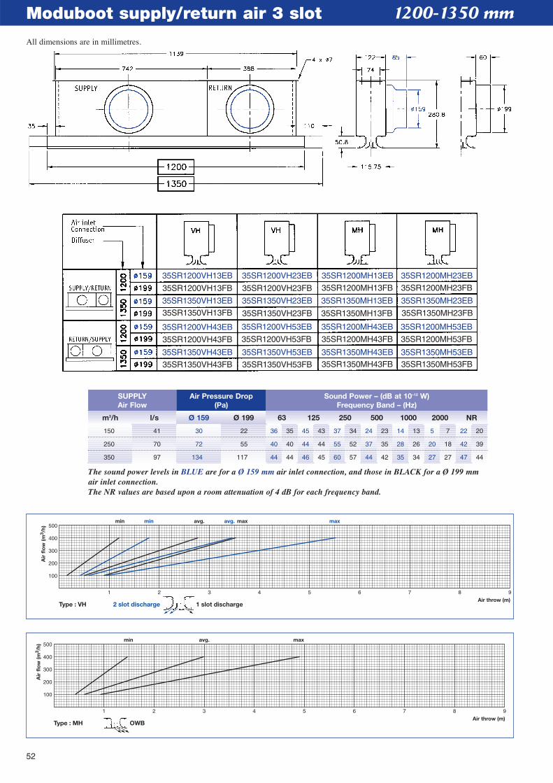
52
Moduboot supply/return air 3 slot
1 2 3 4 5 6 7 8 9Air throw (m)
min avg. max
100
200
300
400
500
Air
flo
w (m
3 /h)
Type : MH OWB
1 2 3 4 5 6 7 8 9Air throw (m)
Air
flo
w (m
3 /h)
min avg. maxmin avg. max
100
200
300
400
500
Type : VH 2 slot discharge 1 slot discharge
1200-1350 mm
m3/h l/s Ø 159 Ø 199 63 125 250 500 1000 2000 NR
SUPPLYAir Flow
Air Pressure Drop(Pa)
Sound Power – (dB at 10–12 W)Frequency Band – (Hz)
150 41 30 22 36 35 45 43 37 34 24 23 14 13 5 7 22 20
250 70 72 55 40 40 44 44 55 52 37 35 28 26 20 18 42 39
350 97 134 117 44 44 46 45 60 57 44 42 35 34 27 27 47 44
The sound power levels in BLUE are for a Ø 159 mm air inlet connection, and those in BLACK for a Ø 199 mmair inlet connection.The NR values are based upon a room attenuation of 4 dB for each frequency band.
35SR1200VH13EB 35SR1200VH23EB 35SR1200MH13EB 35SR1200MH23EB
35SR1200VH13FB 35SR1200VH23FB 35SR1200MH13FB 35SR1200MH23FB
35SR1350VH13EB
35SR1350VH13FB
35SR1200VH43EB
35SR1200VH43FB
35SR1350VH43EB
35SR1350VH43FB
35SR1350VH23EB
35SR1350VH23FB
35SR1200VH53EB
35SR1200VH53FB
35SR1350VH53EB
35SR1350VH53FB
35SR1350MH13EB
35SR1350MH13FB
35SR1200MH43EB
35SR1200MH43FB
35SR1350MH43EB35SR1350MH43FB
35SR1350MH23EB
35SR1350MH23FB
35SR1200MH53EB
35SR1200MH53FB
35SR1350MH53EB35SR1350MH53FB
All dimensions are in millimetres.
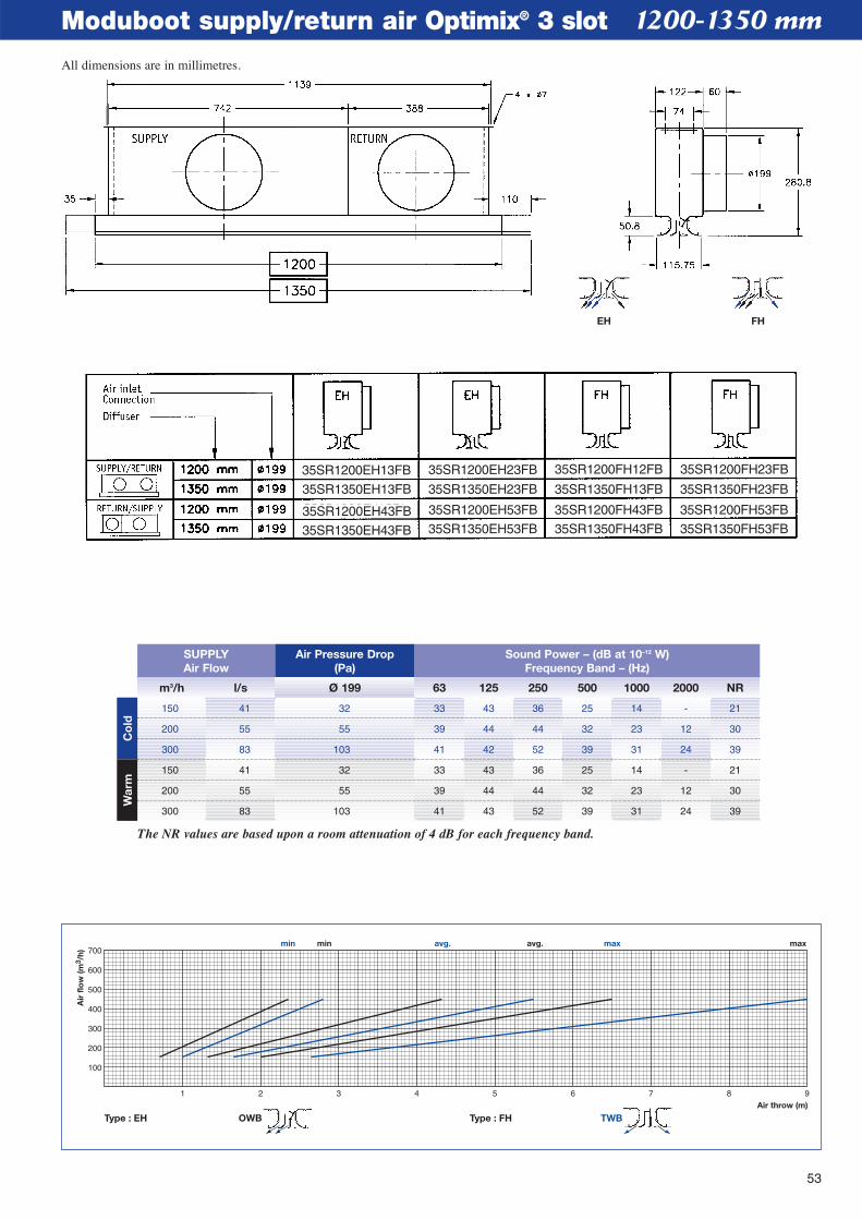
53
Moduboot supply/return air Optimix® 3 slot
1 2 3 4 5 6 7 8 9Air throw (m)
min avg. maxmin avg. max
100
200
300
400
500
600
700
Air
flo
w (m
3 /h)
Type : EH Type : FH TWBOWB
1200-1350 mm
m3/h l/s Ø 199 63 125 250 500 1000 2000 NR
SUPPLYAir Flow
Air Pressure Drop(Pa)
Sound Power – (dB at 10–12 W)Frequency Band – (Hz)
150 41 32 33 43 36 25 14 - 21
200 55 55 39 44 44 32 23 12 30
300 83 103 41 42 52 39 31 24 39
150 41 32 33 43 36 25 14 - 21
200 55 55 39 44 44 32 23 12 30
300 83 103 41 43 52 39 31 24 39
The NR values are based upon a room attenuation of 4 dB for each frequency band.
Co
ldW
arm
EH FH
35SR1200EH13FB
35SR1350EH13FB
35SR1200EH43FB
35SR1350EH43FB
35SR1200EH23FB
35SR1350EH23FB
35SR1200EH53FB
35SR1350EH53FB
35SR1200FH12FB
35SR1350FH13FB
35SR1200FH43FB
35SR1350FH43FB
35SR1200FH23FB
35SR1350FH23FB
35SR1200FH53FB
35SR1350FH53FB
All dimensions are in millimetres.
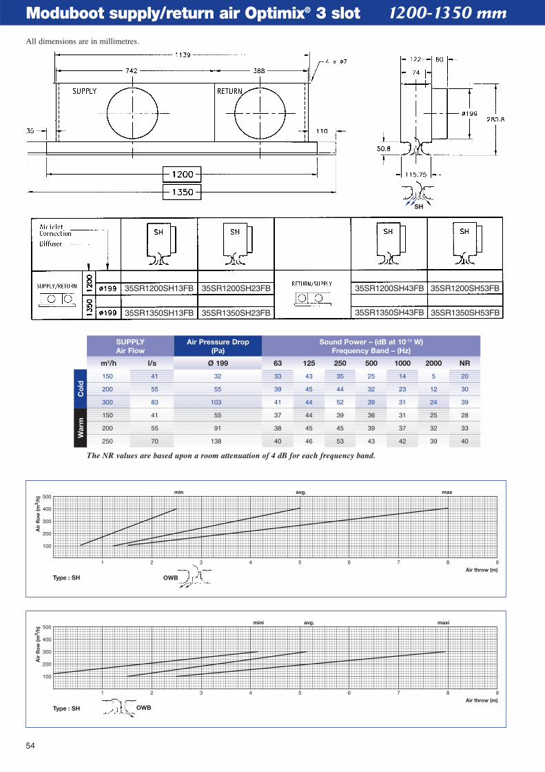
54
Moduboot supply/return air Optimix® 3 slot
1 2 3 4 5 6 7 8 9Air throw (m)
mini avg. maxi
100
200
300
400
500
Air
flo
w (m
3 /h)
Type : SH OWB
1 2 3 4 5 6 7 8 9Air throw (m)
min avg. max
100
200
300
400
500
Air
flo
w (m
3 /h)
Type : SH OWB
1200-1350 mm
m3/h l/s Ø 199 63 125 250 500 1000 2000 NR
SUPPLYAir Flow
Air Pressure Drop(Pa)
Sound Power – (dB at 10–12 W)Frequency Band – (Hz)
150 41 32 33 43 35 25 14 5 20
200 55 55 39 45 44 32 23 12 30
300 83 103 41 44 52 39 31 24 39
150 41 55 37 44 39 36 31 25 28
200 55 91 38 45 45 39 37 32 33
250 70 138 40 46 53 43 42 39 40
The NR values are based upon a room attenuation of 4 dB for each frequency band.
Co
ldW
arm
SH
35SR1200SH13FB
35SR1350SH13FB
35SR1200SH23FB
35SR1350SH23FB
35SR1200SH43FB
35SR1350SH43FB
35SR1200SH53FB
35SR1350SH53FB
All dimensions are in millimetres.
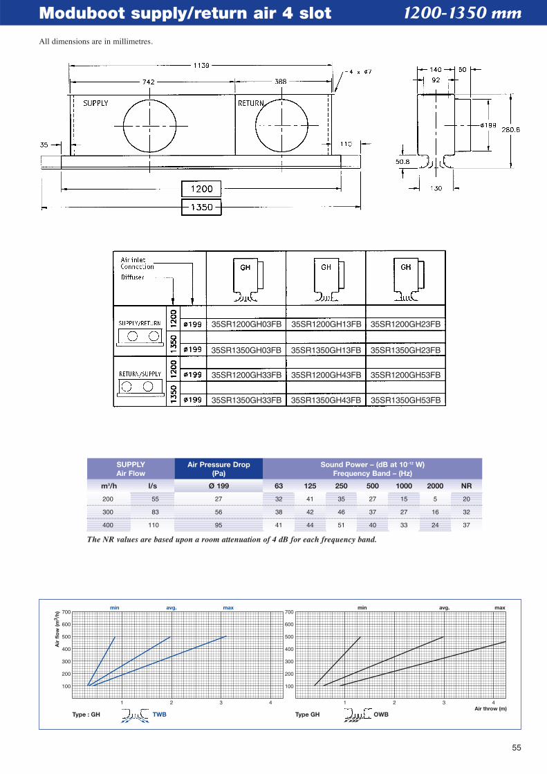
55
Moduboot supply/return air 4 slot
1 2 3 4Air throw (m)
100
200
300
400
500
600
700
100
200
300
400
500
600
700min avg. max
Air
flo
w (m
3 /h)
1 2 3 4
min avg. max
Type : GH Type GHTWB OWB
1200-1350 mm
m3/h l/s Ø 199 63 125 250 500 1000 2000 NR
SUPPLYAir Flow
Air Pressure Drop(Pa)
Sound Power – (dB at 10–12 W)Frequency Band – (Hz)
200 55 27 32 41 35 27 15 5 20
300 83 56 38 42 46 37 27 16 32
400 110 95 41 44 51 40 33 24 37
The NR values are based upon a room attenuation of 4 dB for each frequency band.
35SR1200GH03FB
35SR1350GH03FB
35SR1200GH33FB
35SR1350GH33FB
35SR1200GH13FB
35SR1350GH13FB
35SR1200GH43FB
35SR1350GH43FB
35SR1200GH23FB
35SR1350GH23FB
35SR1200GH53FB
35SR1350GH53FB
All dimensions are in millimetres.
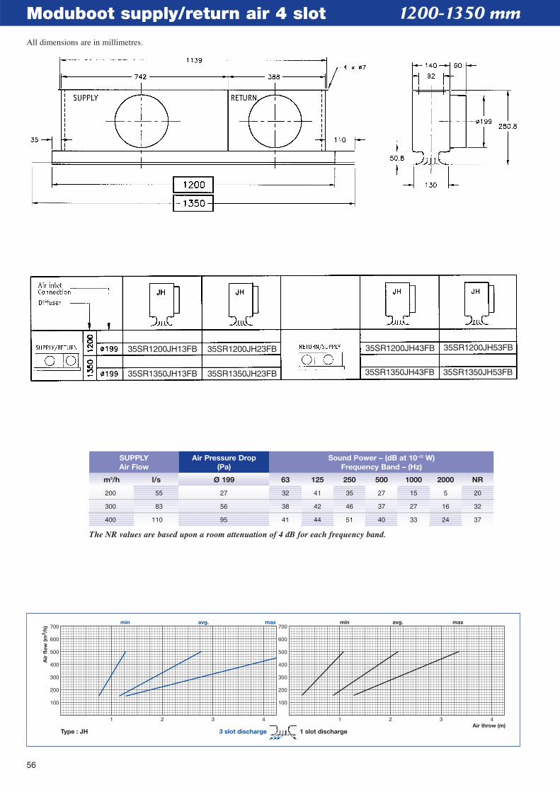
56
Moduboot supply/return air 4 slot
1 2 3 4Air throw (m)
100
200
300
400
500
600
700
100
200
300
400
500
600
700min avg. max
Air
flo
w (m
3 /h)
1 2 3 4
min avg. max
Type : JH 3 slot discharge 1 slot discharge
1200-1350 mm
m3/h l/s Ø 199 63 125 250 500 1000 2000 NR
SUPPLYAir Flow
Air Pressure Drop(Pa)
Sound Power – (dB at 10–12 W)Frequency Band – (Hz)
200 55 27 32 41 35 27 15 5 20
300 83 56 38 42 46 37 27 16 32
400 110 95 41 44 51 40 33 24 37
The NR values are based upon a room attenuation of 4 dB for each frequency band.
35SR1200JH13FB 35SR1200JH23FB 35SR1200JH43FB 35SR1200JH53FB
35SR1350JH13FB 35SR1350JH23FB 35SR1350JH43FB 35SR1350JH53FB
All dimensions are in millimetres.
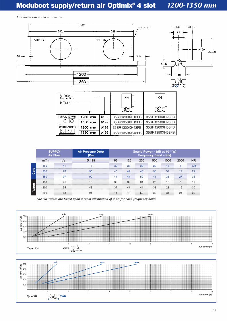
57
Moduboot supply/return air Optimix® 4 slot
1 2 3 4 5 6 7 8 9Air throw (m)
min avg. max
100
200
300
400
500
Air
flo
w (m
3 /h)
Type XH TWB
1 2 3 4 5 6 7 8 9Air throw (m)
min avg. max
100
200
300
400
500
Air
flo
w (m
3 /h)
Type : XH OWB
1200-1350 mm
m3/h l/s Ø 199 63 125 250 500 1000 2000 NR
SUPPLYAir Flow
Air Pressure Drop(Pa)
Sound Power – (dB at 10–12 W)Frequency Band – (Hz)
150 41 5 32 38 32 20 15 5 <20
250 70 50 40 42 43 36 32 17 29
350 97 90 41 44 50 41 35 27 36
150 41 13 32 39 34 25 16 5 19
200 55 43 37 44 44 33 23 16 30
300 83 91 41 43 52 39 31 24 39
The NR values are based upon a room attenuation of 4 dB for each frequency band.
Co
ldW
arm
35SR1200XH13FB 35SR1200XH23FB
35SR1350XH23FB
35SR1200XH53FB
35SR1350XH53FB
35SR1350XH13FB
35SR1200XH43FB
35SR1350XH43FB
All dimensions are in millimetres.
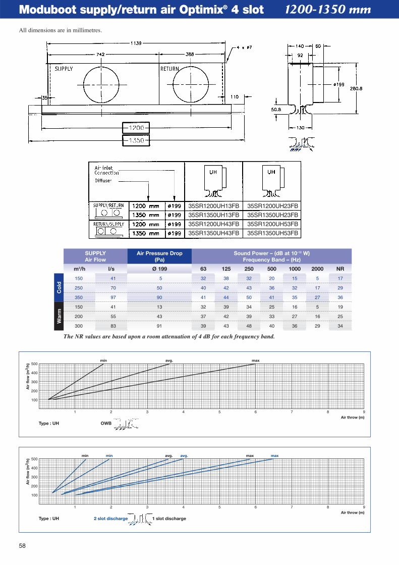
58
Moduboot supply/return air Optimix® 4 slot
1 2 3 4 5 6 7 8 9Air throw (m)
min avg. maxmin avg. max
100
200
300
400
500
Air
flo
w (m
3 /h)
Type : UH 1 slot discharge2 slot discharge
1 2 3 4 5 6 7 8 9Air throw (m)
min avg. max
100
200
300
400
500
Air
flo
w (m
3 /h)
Type : UH OWB
1200-1350 mm
m3/h l/s Ø 199 63 125 250 500 1000 2000 NR
SUPPLYAir Flow
Air Pressure Drop(Pa)
Sound Power – (dB at 10–12 W)Frequency Band – (Hz)
150 41 5 32 38 32 20 15 5 17
250 70 50 40 42 43 36 32 17 29
350 97 90 41 44 50 41 35 27 36
150 41 13 32 39 34 25 16 5 19
200 55 43 37 42 39 33 27 16 25
300 83 91 39 43 48 40 36 29 34
The NR values are based upon a room attenuation of 4 dB for each frequency band.
Co
ldW
arm
35SR1200UH13FB 35SR1200UH23FB
35SR1350UH23FB
35SR1200UH53FB
35SR1350UH53FB
35SR1350UH13FB
35SR1200UH43FB
35SR1350UH43FB
All dimensions are in millimetres.
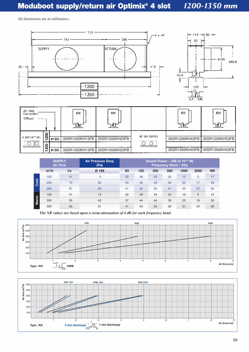
59
Moduboot supply/return air Optimix® 4 slot
1 2 3 4 5 6 7 8 9
100
200
300
400
500
600
Air throw (m)
min avg. max
Air
flo
w (m
3 /h)
Type : KH 2 slot discharge
min avg. max
1 slot discharge
1 2 3 4 5 6 7 8 9Air throw (m)
min avg. max
100
200
300
400
500
600
Air
flo
w (m
3 /h)
Type : KH OWB
1200-1350 mm
m3/h l/s Ø 199 63 125 250 500 1000 2000 NR
SUPPLYAir Flow
Air Pressure Drop(Pa)
Sound Power – (dB at 10–12 W)Frequency Band – (Hz)
150 41 5 32 38 32 20 15 5 17
250 70 50 40 42 43 36 32 17 29
350 97 90 41 44 50 41 35 27 36
150 41 13 32 39 34 25 16 5 19
200 55 43 37 44 44 33 23 16 30
300 83 91 41 43 52 39 31 24 39
The NR values are based upon a room attenuation of 4 dB for each frequency band.
Co
ldW
arm
35SR1200KH13FB 35SR1200KH23FB
35SR1350KH13FB 35SR1350KH23FB
35SR1200KH43FB
35SR1350KH43FB
35SR1200KH53FB
35SR1350KH53FB
All dimensions are in millimetres.
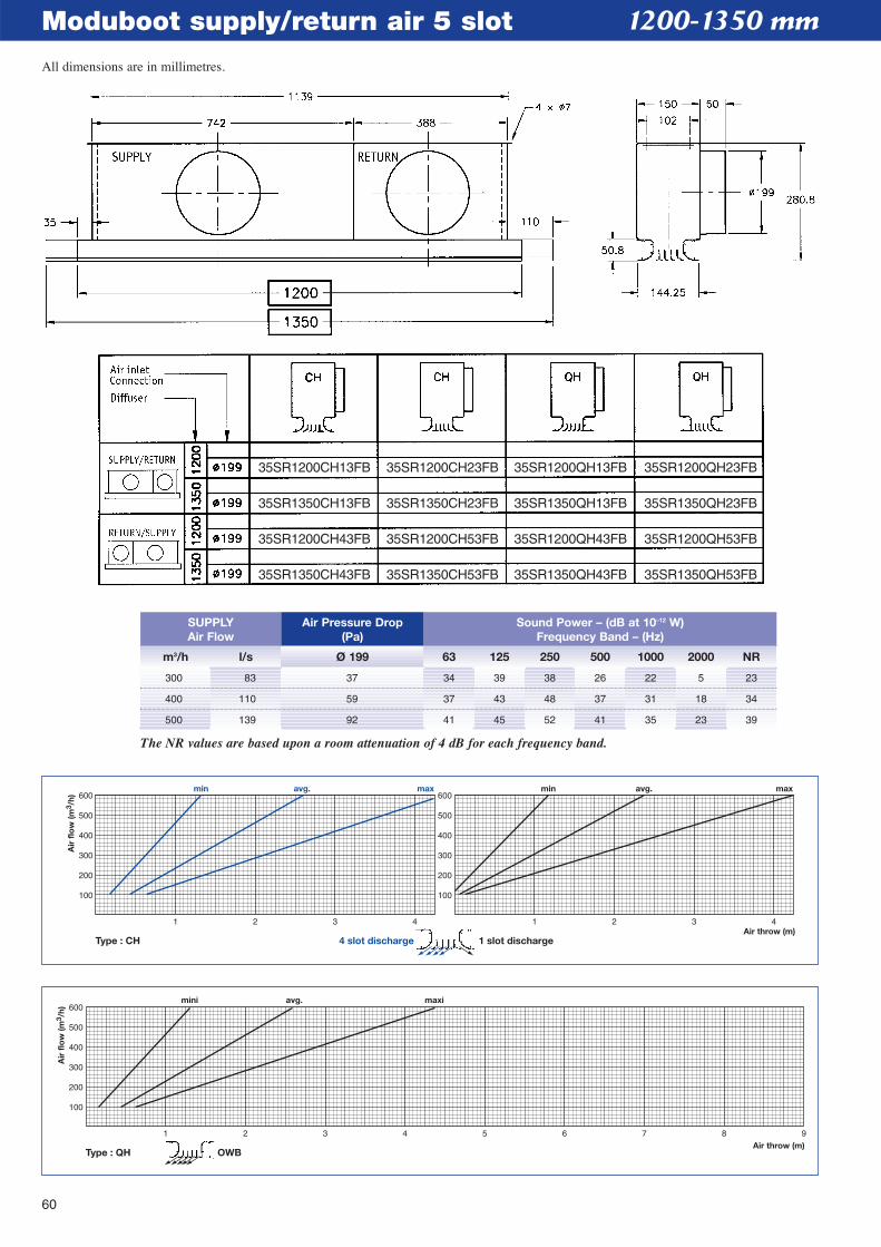
60
Moduboot supply/return air 5 slot
1 2 3 4 5 6 7 8 9Air throw (m)
mini avg. maxi
100
200
300
400
500
600
Air
flo
w (m
3 /h)
Type : QH OWB
1 2 3 4Air throw (m)
100
200
300
400
500
600
100
200
300
400
500
600
Air
flo
w (m
3 /h)
1 2 3 4
min avg. maxmin avg. max
Type : CH 4 slot discharge 1 slot discharge
1200-1350 mm
m3/h l/s Ø 199 63 125 250 500 1000 2000 NR
SUPPLYAir Flow
Air Pressure Drop(Pa)
Sound Power – (dB at 10–12 W)Frequency Band – (Hz)
300 83 37 34 39 38 26 22 5 23
400 110 59 37 43 48 37 31 18 34
500 139 92 41 45 52 41 35 23 39
The NR values are based upon a room attenuation of 4 dB for each frequency band.
35SR1200CH13FB
35SR1350CH13FB
35SR1200CH43FB
35SR1350CH43FB
35SR1200CH23FB
35SR1350CH23FB
35SR1200CH53FB
35SR1350CH53FB
35SR1200QH13FB
35SR1350QH13FB
35SR1200QH43FB
35SR1350QH43FB
35SR1200QH23FB
35SR1350QH23FB
35SR1200QH53FB
35SR1350QH53FB
All dimensions are in millimetres.
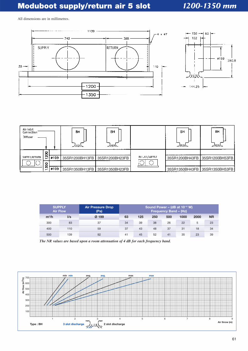
61
Moduboot supply/return air 5 slot
1 2 3 4 5 6 7 8 9Air throw (m)
min avg. maxmin avg. max
100
200
300
400
500
600
700
Air
flo
w (m
3 /h)
Type : BH 3 slot discharge 2 slot discharge
1200-1350 mm
m3/h l/s Ø 199 63 125 250 500 1000 2000 NR
SUPPLYAir Flow
Air Pressure Drop(Pa)
Sound Power – (dB at 10–12 W)Frequency Band – (Hz)
300 83 37 34 39 38 26 22 5 23
400 110 59 37 43 48 37 31 18 34
500 139 92 41 45 52 41 35 23 39
The NR values are based upon a room attenuation of 4 dB for each frequency band.
35SR1200BH13FB 35SR1200BH23FB
35SR1350BH13FB 35SR1350BH23FB
35SR1200BH43FB 35SR1200BH53FB
35SR1350BH43FB 35SR1350BH53FB
All dimensions are in millimetres.
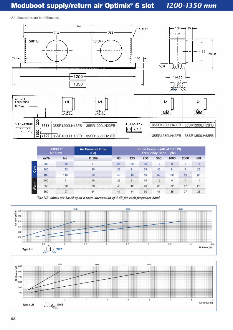
62
Moduboot supply/return air Optimix® 5 slot
1 2 3 4 5 6 7 8 9Air throw (m)
min avg. max
100
200
300
400
500
600
Air
flo
w (m
3 /h)
Type : LH OWB
0.5 1 1.5 2 2.5 3 3.5 4 4.5Air throw (m)
min avg. max
100
200
300
400
500
600
Air
flo
w (m
3 /h)
Type LH TWB
1200-1350 mm
m3/h l/s Ø 199 63 125 250 500 1000 2000 NR
SUPPLYAir Flow
Air Pressure Drop(Pa)
Sound Power – (dB at 10–12 W)Frequency Band – (Hz)
200 55 11 28 39 29 17 9 3 15
300 83 30 36 41 39 30 21 7 25
400 113 62 40 43 49 37 30 19 35
150 41 16 28 31 26 15 9 4 14
250 70 38 40 42 43 36 32 17 29
350 97 64 41 44 50 41 35 27 36
The NR values are based upon a room attenuation of 4 dB for each frequency band.
Co
ldW
arm
35SR1200LH13FB
35SR1350LH13FB
35SR1200LH23FB
35SR1350LH23FB
35SR1200LH43FB
35SR1350LH43FB
35SR1200LH53FB
35SR1350LH53FB
All dimensions are in millimetres.
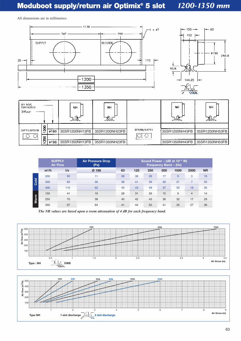
63
Moduboot supply/return air Optimix® 5 slot
1 2 3 4 5 6 7 8 9Air throw (m)
min avg. maxmin avg. max
100
200
300
400
500
Air
flo
w (m
3 /h)
Type NH 2 slot discharge1 slot discharge
0.5 1 1.5 2 2.5 3 3.5 4 4.5Air throw (m)
min avg. max
100
200
300
400
500
Air
flo
w (m
3 /h)
Type : NH OWB
1200-1350 mm
m3/h l/s Ø 199 63 125 250 500 1000 2000 NR
SUPPLYAir Flow
Air Pressure Drop(Pa)
Sound Power – (dB at 10–12 W)Frequency Band – (Hz)
200 55 11 28 39 29 17 9 3 15
300 83 30 36 41 39 30 21 7 25
400 110 62 40 43 49 37 30 19 35
150 41 16 28 31 26 15 9 4 14
250 70 38 40 42 43 36 32 17 29
350 97 64 41 44 50 41 35 27 36
The NR values are based upon a room attenuation of 4 dB for each frequency band.
Co
ldW
arm
35SR1200NH13FB
35SR1350NH13FB
35SR1200NH23FB
35SR1350NH23FB
35SR1200NH43FB
35SR1350NH43FB
35SR1200NH53FB
35SR1350NH53FB
All dimensions are in millimetres.
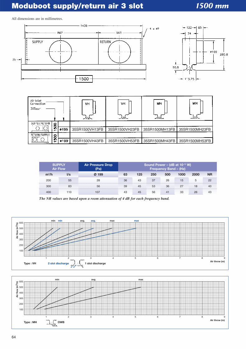
64
Moduboot supply/return air 3 slot
1 2 3 4 5 6 7 8 9Air throw (m)
min avg. max
100
200
300
400
500
600
Air
flo
w (m
3 /h)
Type : MH OWB
1 2 3 4 5 6 7 8 9Air throw (m)
min avg. maxmin avg. max
100
200
300
400
500
600
Air
flo
w (m
3 /h)
Type : VH 2 slot discharge 1 slot discharge
1500 mm
m3/h l/s Ø 199 63 125 250 500 1000 2000 NR
SUPPLYAir Flow
Air Pressure Drop(Pa)
Sound Power – (dB at 10–12 W)Frequency Band – (Hz)
200 55 28 36 43 37 26 15 5 22
300 83 56 39 45 53 36 27 18 40
400 110 107 43 45 56 41 33 26 43
The NR values are based upon a room attenuation of 4 dB for each frequency band.
35SR1500VH13FB
35SR1500VH43FB
35SR1500VH23FB
35SR1500VH53FB
35SR1500MH13FB
35SR1500MH43FB
35SR1500MH23FB
35SR1500MH53FB
All dimensions are in millimetres.
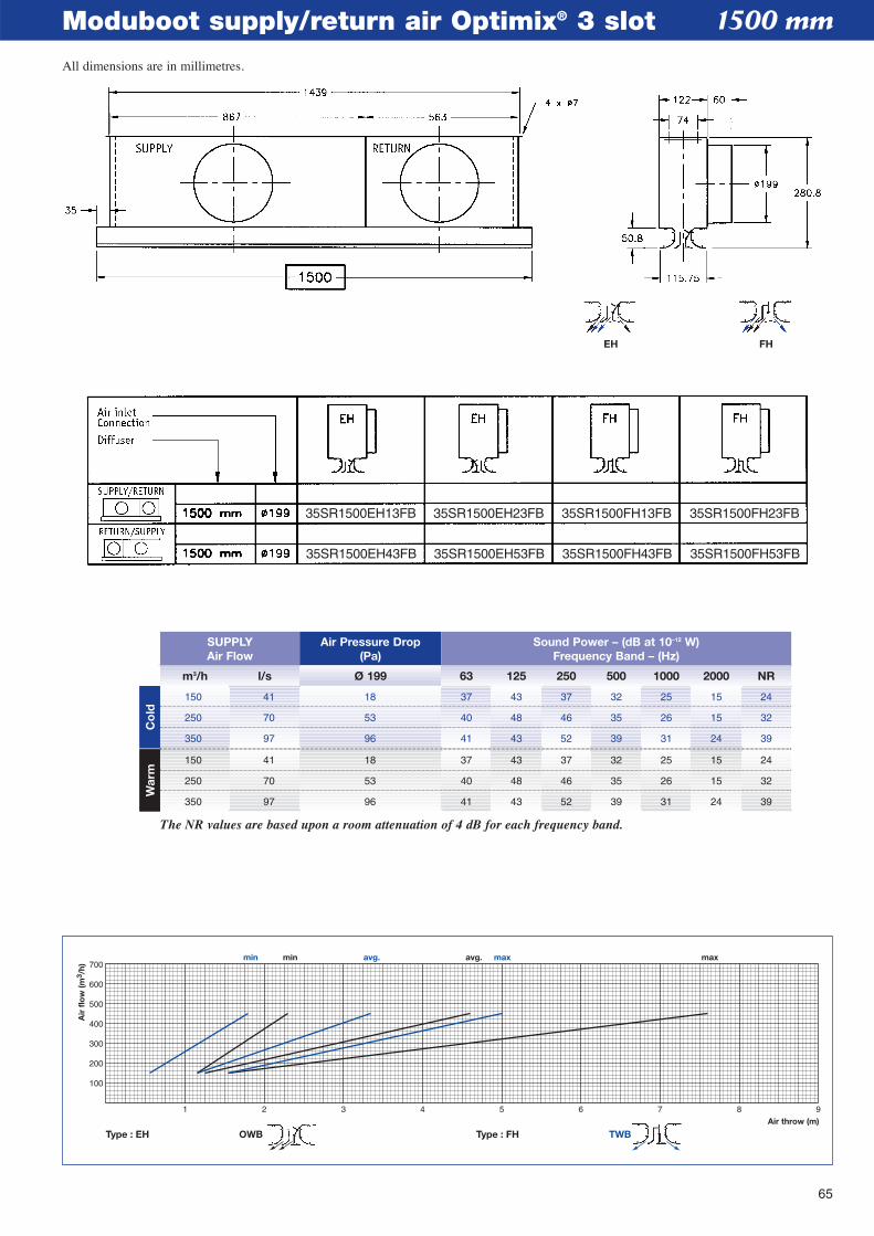
65
Moduboot supply/return air Optimix® 3 slot
1 2 3 4 5 6 7 8 9Air throw (m)
min avg. maxmin avg. max
100
200
300
400
500
600
700
Air
flo
w (m
3 /h)
Type : EH Type : FH TWBOWB
1500 mm
m3/h l/s Ø 199 63 125 250 500 1000 2000 NR
SUPPLYAir Flow
Air Pressure Drop(Pa)
Sound Power – (dB at 10–12 W)Frequency Band – (Hz)
150 41 18 37 43 37 32 25 15 24
250 70 53 40 48 46 35 26 15 32
350 97 96 41 43 52 39 31 24 39
150 41 18 37 43 37 32 25 15 24
250 70 53 40 48 46 35 26 15 32
350 97 96 41 43 52 39 31 24 39
The NR values are based upon a room attenuation of 4 dB for each frequency band.
Co
ldW
arm
EH FH
35SR1500EH13FB
35SR1500EH43FB
35SR1500EH23FB
35SR1500EH53FB
35SR1500FH13FB
35SR1500FH43FB
35SR1500FH23FB
35SR1500FH53FB
All dimensions are in millimetres.
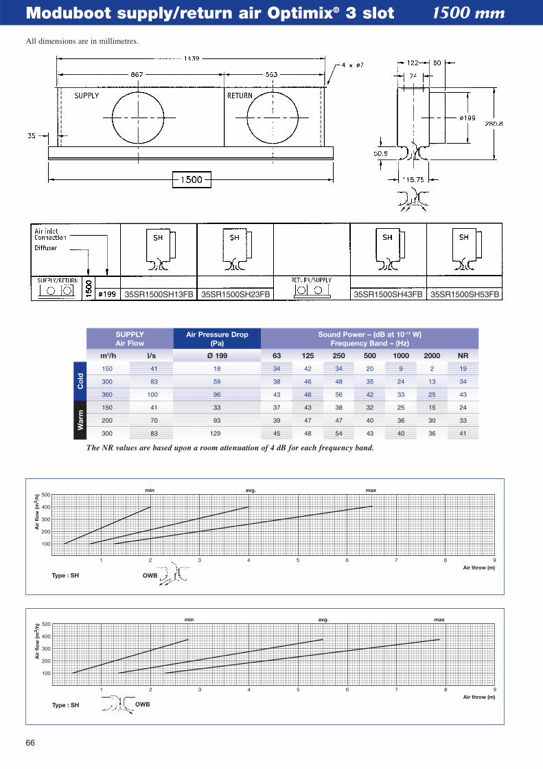
66
Moduboot supply/return air Optimix® 3 slot
1 2 3 4 5 6 7 8 9Air throw (m)
min avg. max
100
200
300
400
500
Air
flo
w (m
3 /h)
Type : SH OWB
1 2 3 4 5 6 7 8 9Air throw (m)
min avg. max
100
200
300
400
500
Air
flo
w (m
3 /h)
Type : SH OWB
1500 mm
m3/h l/s Ø 199 63 125 250 500 1000 2000 NR
SUPPLYAir Flow
Air Pressure Drop(Pa)
Sound Power – (dB at 10–12 W)Frequency Band – (Hz)
150 41 18 34 42 34 20 9 2 19
300 83 59 38 46 48 35 24 13 34
360 100 96 43 46 56 42 33 25 43
150 41 33 37 43 38 32 25 15 24
200 70 93 39 47 47 40 36 30 33
300 83 129 45 48 54 43 40 36 41
The NR values are based upon a room attenuation of 4 dB for each frequency band.
Co
ldW
arm
35SR1500SH13FB 35SR1500SH23FB 35SR1500SH43FB 35SR1500SH53FB
All dimensions are in millimetres.
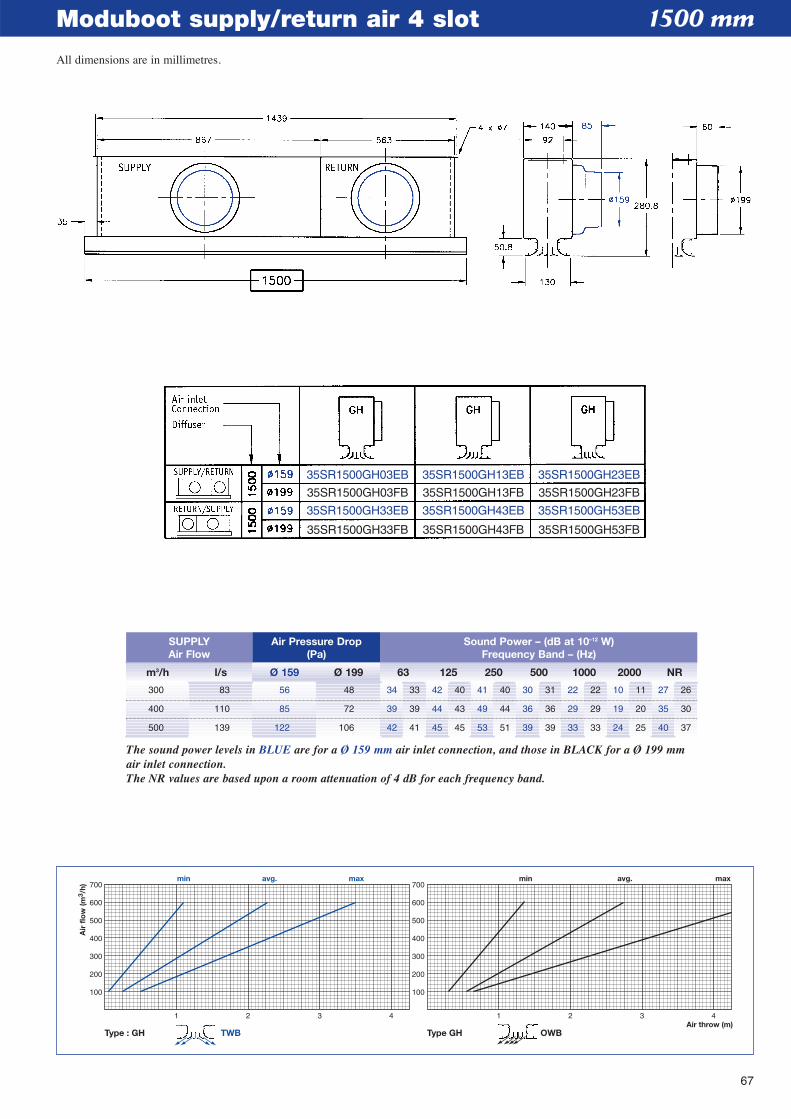
67
Moduboot supply/return air 4 slot
1 2 3 4Air throw (m)
100
200
300
400
500
600
700
100
200
300
400
500
600
700min avg. max
Air
flo
w (m
3 /h)
1 2 3 4
min avg. max
Type : GH Type GHTWB OWB
1500 mm
m3/h l/s Ø 159 Ø 199 63 125 250 500 1000 2000 NR
SUPPLYAir Flow
Air Pressure Drop(Pa)
Sound Power – (dB at 10–12 W)Frequency Band – (Hz)
300 83 56 48 34 33 42 40 41 40 30 31 22 22 10 11 27 26
400 110 85 72 39 39 44 43 49 44 36 36 29 29 19 20 35 30
500 139 122 106 42 41 45 45 53 51 39 39 33 33 24 25 40 37
The sound power levels in BLUE are for a Ø 159 mm air inlet connection, and those in BLACK for a Ø 199 mmair inlet connection.The NR values are based upon a room attenuation of 4 dB for each frequency band.
35SR1500GH03EB 35SR1500GH13EB 35SR1500GH23EB
35SR1500GH03FB
35SR1500GH33EB
35SR1500GH33FB
35SR1500GH13FB
35SR1500GH43EB
35SR1500GH43FB
35SR1500GH23FB
35SR1500GH53EB
35SR1500GH53FB
All dimensions are in millimetres.
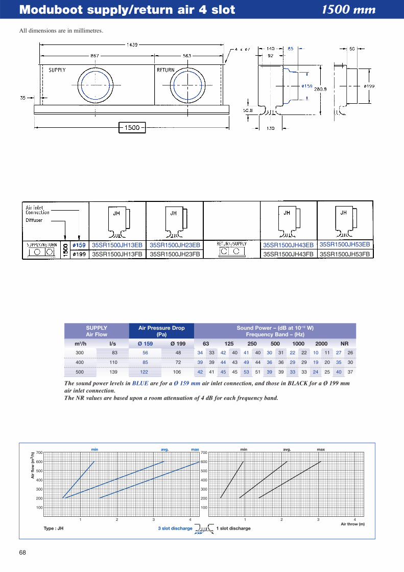
68
Moduboot supply/return air 4 slot
1 2 3 4Air throw (m)
100
200
300
400
500
600
700
100
200
300
400
500
600
700min avg. max
Air
flo
w (m
3 /h)
1 2 3 4
min avg. max
Type : JH 3 slot discharge 1 slot discharge
1500 mm
m3/h l/s Ø 159 Ø 199 63 125 250 500 1000 2000 NR
SUPPLYAir Flow
Air Pressure Drop(Pa)
Sound Power – (dB at 10–12 W)Frequency Band – (Hz)
300 83 56 48 34 33 42 40 41 40 30 31 22 22 10 11 27 26
400 110 85 72 39 39 44 43 49 44 36 36 29 29 19 20 35 30
500 139 122 106 42 41 45 45 53 51 39 39 33 33 24 25 40 37
The sound power levels in BLUE are for a Ø 159 mm air inlet connection, and those in BLACK for a Ø 199 mmair inlet connection.The NR values are based upon a room attenuation of 4 dB for each frequency band.
35SR1500JH13EB
35SR1500JH13FB
35SR1500JH23EB
35SR1500JH23FB
35SR1500JH43EB
35SR1500JH43FB
35SR1500JH53EB
35SR1500JH53FB
All dimensions are in millimetres.
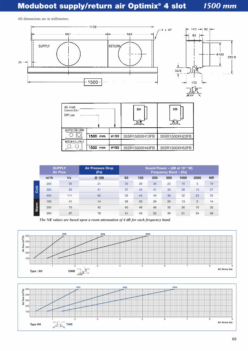
69
Moduboot supply/return air Optimix® 4 slot
1 2 3 4 5 6 7 8 9Air throw (m)
min avg. max
100
200
300
400
500
Air
flo
w (m
3 /h)
Type XH TWB
Air throw (m)
min avg. max
100
200
300
400
500
Air
flo
w (m
3 /h)
1 2 3 4 5 6 7 8 9
Type : XH OWB
1500 mm
m3/h l/s Ø 199 63 125 250 500 1000 2000 NR
SUPPLYAir Flow
Air Pressure Drop(Pa)
Sound Power – (dB at 10–12 W)Frequency Band – (Hz)
200 55 21 33 39 34 23 15 5 19
300 83 41 37 43 41 33 28 13 27
400 111 80 39 44 49 38 32 23 35
150 41 14 28 33 29 20 13 5 14
250 70 42 40 48 46 35 26 15 32
350 97 78 41 43 52 39 31 24 39
The NR values are based upon a room attenuation of 4 dB for each frequency band.
Co
ldW
arm
35SR1500XH13FB 35SR1500XH23FB
35SR1500XH43FB 35SR1500XH53FB
All dimensions are in millimetres.
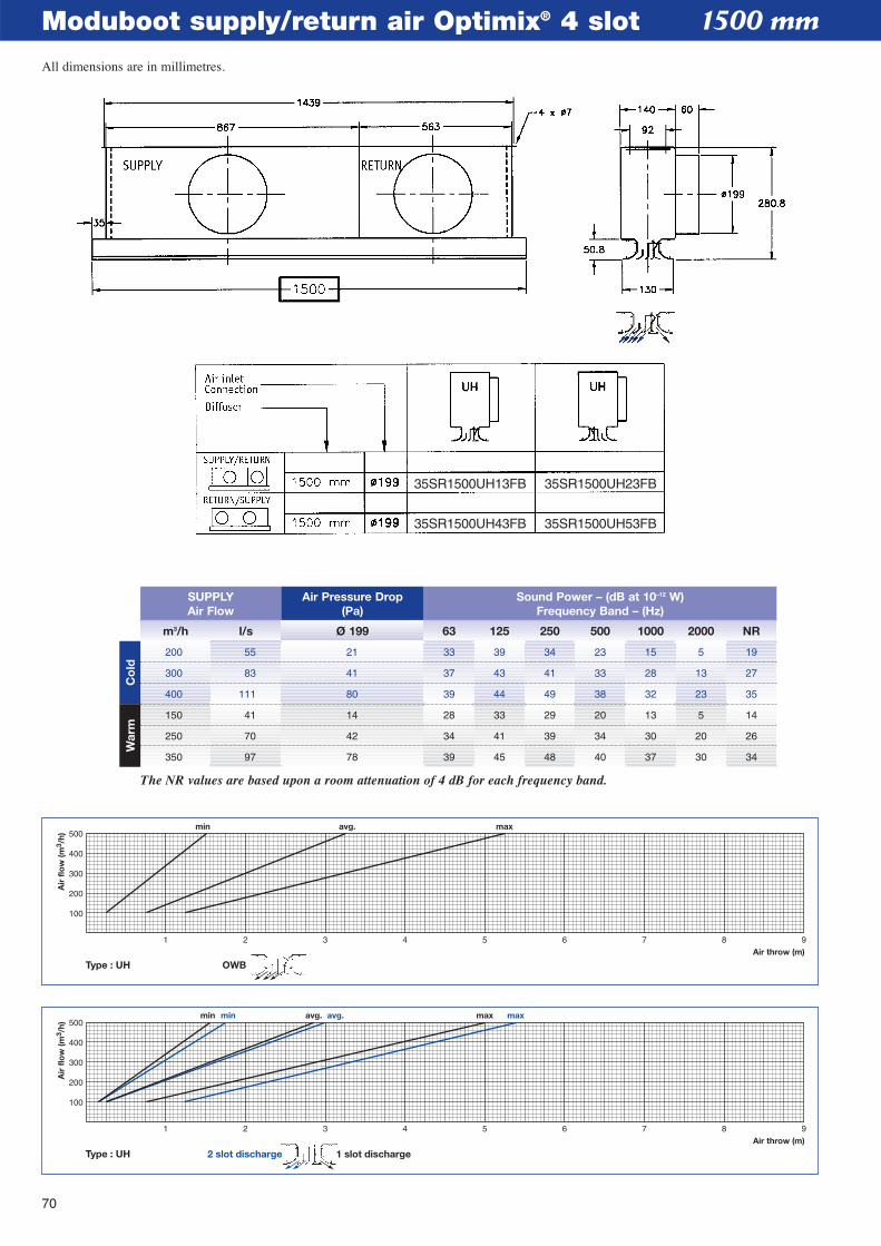
70
Moduboot supply/return air Optimix® 4 slot
1 2 3 4 5 6 7 8 9Air throw (m)
min avg. maxmin avg. max
100
200
300
400
500
Air
flo
w (m
3 /h)
Type : UH 1 slot discharge2 slot discharge
Air throw (m)
min avg. max
100
200
300
400
500
Air
flo
w (m
3 /h)
1 2 3 4 5 6 7 8 9
Type : UH OWB
1500 mm
m3/h l/s Ø 199 63 125 250 500 1000 2000 NR
SUPPLYAir Flow
Air Pressure Drop(Pa)
Sound Power – (dB at 10–12 W)Frequency Band – (Hz)
200 55 21 33 39 34 23 15 5 19
300 83 41 37 43 41 33 28 13 27
400 111 80 39 44 49 38 32 23 35
150 41 14 28 33 29 20 13 5 14
250 70 42 34 41 39 34 30 20 26
350 97 78 39 45 48 40 37 30 34
The NR values are based upon a room attenuation of 4 dB for each frequency band.
Co
ldW
arm
35SR1500UH13FB 35SR1500UH23FB
35SR1500UH43FB 35SR1500UH53FB
All dimensions are in millimetres.
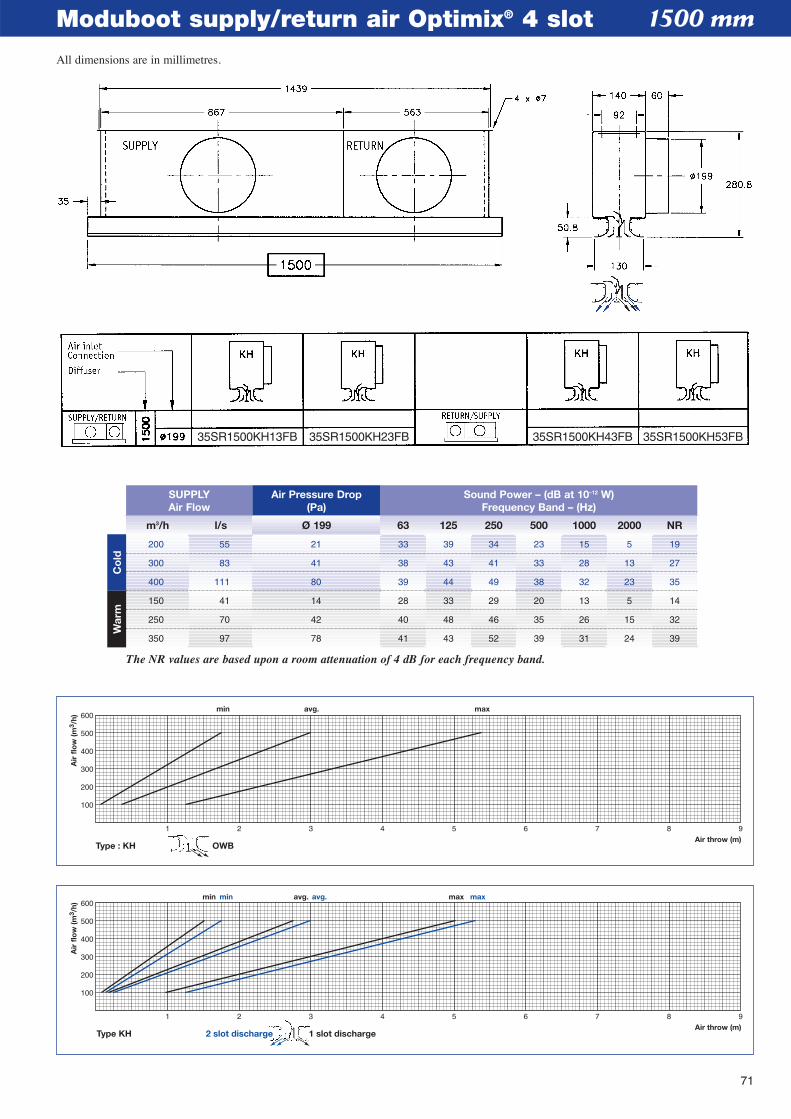
71
Moduboot supply/return air Optimix® 4 slot
1 2 3 4 5 6 7 8 9Air throw (m)
min avg. maxmin avg. max
100
200
300
400
500
600
Air
flo
w (m
3 /h)
Type KH 1 slot discharge2 slot discharge
1 2 3 4 5 6 7 8 9Air throw (m)
min avg. max
100
200
300
400
500
600
Air
flo
w (m
3 /h)
Type : KH OWB
1500 mm
m3/h l/s Ø 199 63 125 250 500 1000 2000 NR
SUPPLYAir Flow
Air Pressure Drop(Pa)
Sound Power – (dB at 10–12 W)Frequency Band – (Hz)
200 55 21 33 39 34 23 15 5 19
300 83 41 38 43 41 33 28 13 27
400 111 80 39 44 49 38 32 23 35
150 41 14 28 33 29 20 13 5 14
250 70 42 40 48 46 35 26 15 32
350 97 78 41 43 52 39 31 24 39
The NR values are based upon a room attenuation of 4 dB for each frequency band.
Co
ldW
arm
35SR1500KH13FB 35SR1500KH23FB 35SR1500KH43FB 35SR1500KH53FB
All dimensions are in millimetres.
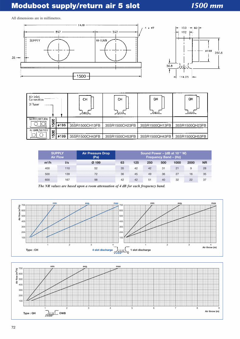
72
Moduboot supply/return air 5 slot
1 2 3 4 5 6 7 8 9Air throw (m)
min avg. max
100
200
300
400
500
600
700
Air
flo
w (m
3 /h)
Type : QH OWB
1 2 3 4Air throw (m)
100
200
300
400
500
600
700
100
200
300
400
500
600
700
Air
flo
w (m
3 /h)
1 2 3 4
min avg. maxmin avg. max
Type : CH 4 slot discharge 1 slot discharge
1500 mm
m3/h l/s Ø 199 63 125 250 500 1000 2000 NR
SUPPLYAir Flow
Air Pressure Drop(Pa)
Sound Power – (dB at 10–12 W)Frequency Band – (Hz)
400 110 52 35 42 42 31 21 9 28
500 139 72 36 45 49 36 27 16 35
600 167 98 42 42 51 40 32 22 37
The NR values are based upon a room attenuation of 4 dB for each frequency band.
35SR1500CH13FB
35SR1500CH43FB
35SR1500CH23FB
35SR1500CH53FB
35SR1500QH13FB
35SR1500QH43FB
35SR1500QH23FB
35SR1500QH53FB
All dimensions are in millimetres.
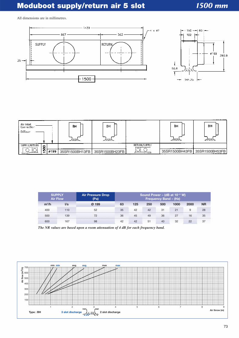
73
Moduboot supply/return air 5 slot
1 2 3 4 5 6 7 8 9Air throw (m)
min avg. maxmin avg. max
100
200
300
400
500
600
700
Air
flo
w (m
3 /h)
Type : BH 3 slot discharge 2 slot discharge
1500 mm
m3/h l/s Ø 199 63 125 250 500 1000 2000 NR
SUPPLYAir Flow
Air Pressure Drop(Pa)
Sound Power – (dB at 10–12 W)Frequency Band – (Hz)
400 110 52 35 42 42 31 21 9 28
500 139 72 36 45 49 36 27 16 35
600 167 98 42 42 51 40 32 22 37
The NR values are based upon a room attenuation of 4 dB for each frequency band.
35SR1500BH13FB 35SR1500BH23FB 35SR1500BH43FB 35SR1500BH53FB
All dimensions are in millimetres.
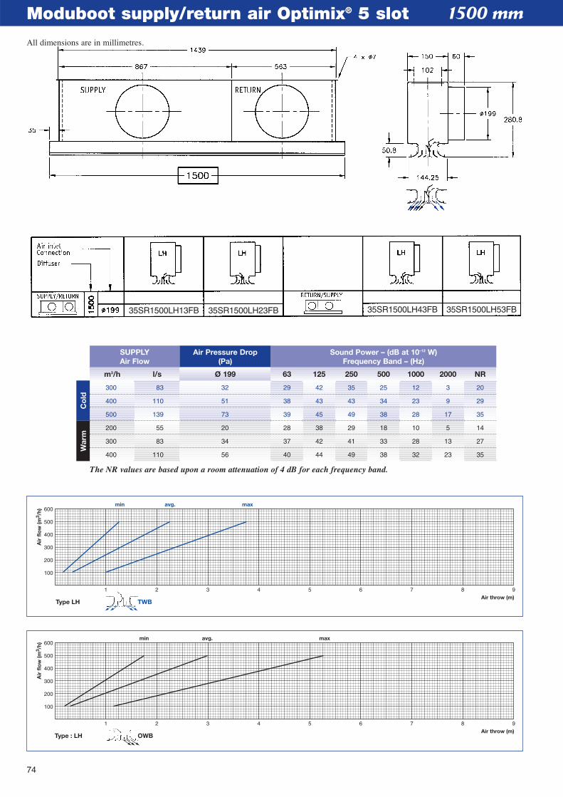
74
Moduboot supply/return air Optimix® 5 slot
1 2 3 4 5 6 7 8 9Air throw (m)
min avg. max
100
200
300
400
500
600
Air
flo
w (m
3 /h)
Type : LH OWB
1 2 3 4 5 6 7 8 9Air throw (m)
min avg. max
100
200
300
400
500
600
Air
flo
w (m
3 /h)
Type LH TWB
1500 mm
m3/h l/s Ø 199 63 125 250 500 1000 2000 NR
SUPPLYAir Flow
Air Pressure Drop(Pa)
Sound Power – (dB at 10–12 W)Frequency Band – (Hz)
300 83 32 29 42 35 25 12 3 20
400 110 51 38 43 43 34 23 9 29
500 139 73 39 45 49 38 28 17 35
200 55 20 28 38 29 18 10 5 14
300 83 34 37 42 41 33 28 13 27
400 110 56 40 44 49 38 32 23 35
The NR values are based upon a room attenuation of 4 dB for each frequency band.
Co
ldW
arm
35SR1500LH13FB 35SR1500LH23FB 35SR1500LH43FB 35SR1500LH53FB
All dimensions are in millimetres.
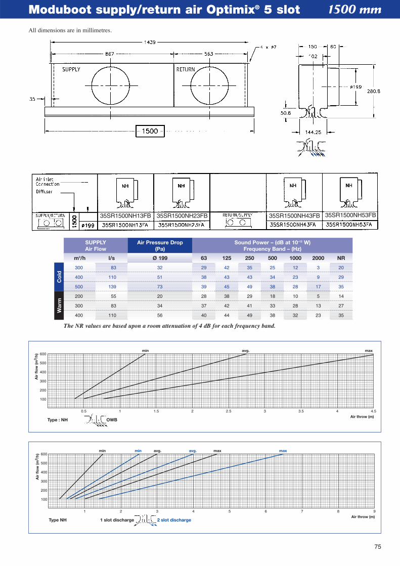
75
Moduboot supply/return air Optimix® 5 slot
1 2 3 4 5 6 7 8 9Air throw (m)
min avg. maxmin avg. max
100
200
300
400
500
600
Air
flo
w (m
3 /h)
Type NH 2 slot discharge1 slot discharge
0.5 1 1.5 2 2.5 3 3.5 4 4.5Air throw (m)
min avg. max
100
200
300
400
500
600
Air
flo
w (m
3 /h)
Type : NH OWB
1500 mm
m3/h l/s Ø 199 63 125 250 500 1000 2000 NR
SUPPLYAir Flow
Air Pressure Drop(Pa)
Sound Power – (dB at 10–12 W)Frequency Band – (Hz)
300 83 32 29 42 35 25 12 3 20
400 110 51 38 43 43 34 23 9 29
500 139 73 39 45 49 38 28 17 35
200 55 20 28 38 29 18 10 5 14
300 83 34 37 42 41 33 28 13 27
400 110 56 40 44 49 38 32 23 35
The NR values are based upon a room attenuation of 4 dB for each frequency band.
Co
ldW
arm
35SR1500NH13FB 35SR1500NH23FB 35SR1500NH43FB 35SR1500NH53FB
All dimensions are in millimetres.
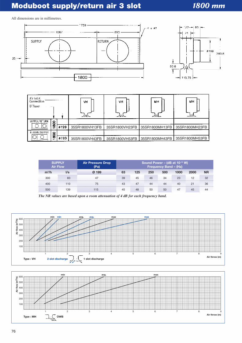
76
Moduboot supply/return air 3 slot
1 2 3 4 5 6 7 8 9Air throw (m)
min avg. max
100
200
300
400
500
600
Air
flo
w (m
3 /h)
Type : MH OWB
1 2 3 4 5 6 7 8 9Air throw (m)
min avg. maxmin avg. max
100
200
300
400
500
600
Air
flo
w (m
3 /h)
Type : VH 2 slot discharge 1 slot discharge
1800 mm
m3/h l/s Ø 199 63 125 250 500 1000 2000 NR
SUPPLYAir Flow
Air Pressure Drop(Pa)
Sound Power – (dB at 10–12 W)Frequency Band – (Hz)
300 83 47 39 45 46 34 23 12 32
400 110 75 43 47 44 44 40 21 36
500 139 115 45 48 50 50 47 45 44
The NR values are based upon a room attenuation of 4 dB for each frequency band.
35SR1800VH13FB
35SR1800VH43FB
35SR1800VH23FB
35SR1800VH53FB
35SR1800MH13FB
35SR1800MH43FB
35SR1800MH23FB
35SR1800MH53FB
All dimensions are in millimetres.
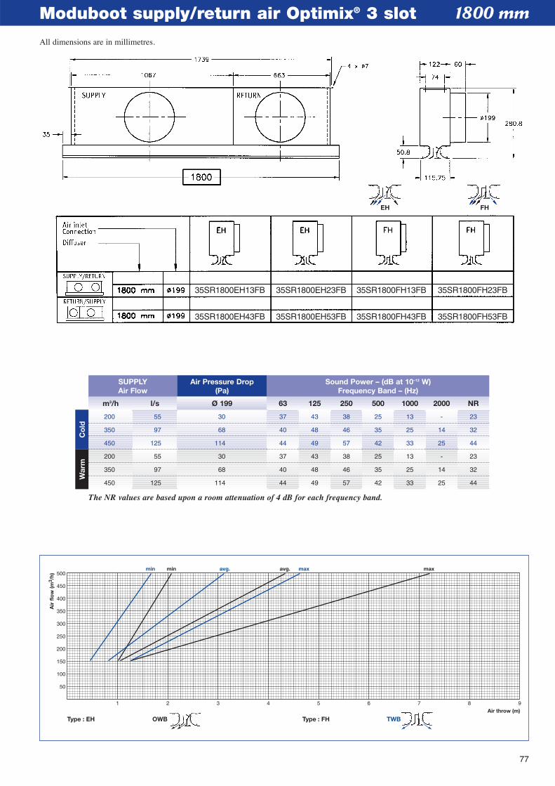
77
Moduboot supply/return air Optimix® 3 slot
1 2 3 4 5 6 7 8 9Air throw (m)
min avg. maxmin avg. max
50
100
150
200
250
300
350
400
450
500
Air
flo
w (m
3 /h)
Type : EH Type : FH TWBOWB
1800 mm
m3/h l/s Ø 199 63 125 250 500 1000 2000 NR
SUPPLYAir Flow
Air Pressure Drop(Pa)
Sound Power – (dB at 10–12 W)Frequency Band – (Hz)
200 55 30 37 43 38 25 13 - 23
350 97 68 40 48 46 35 25 14 32
450 125 114 44 49 57 42 33 25 44
200 55 30 37 43 38 25 13 - 23
350 97 68 40 48 46 35 25 14 32
450 125 114 44 49 57 42 33 25 44
The NR values are based upon a room attenuation of 4 dB for each frequency band.
Co
ldW
arm
EH FH
35SR1800EH13FB
35SR1800EH43FB
35SR1800EH23FB
35SR1800EH53FB
35SR1800FH13FB
35SR1800FH43FB
35SR1800FH23FB
35SR1800FH53FB
All dimensions are in millimetres.
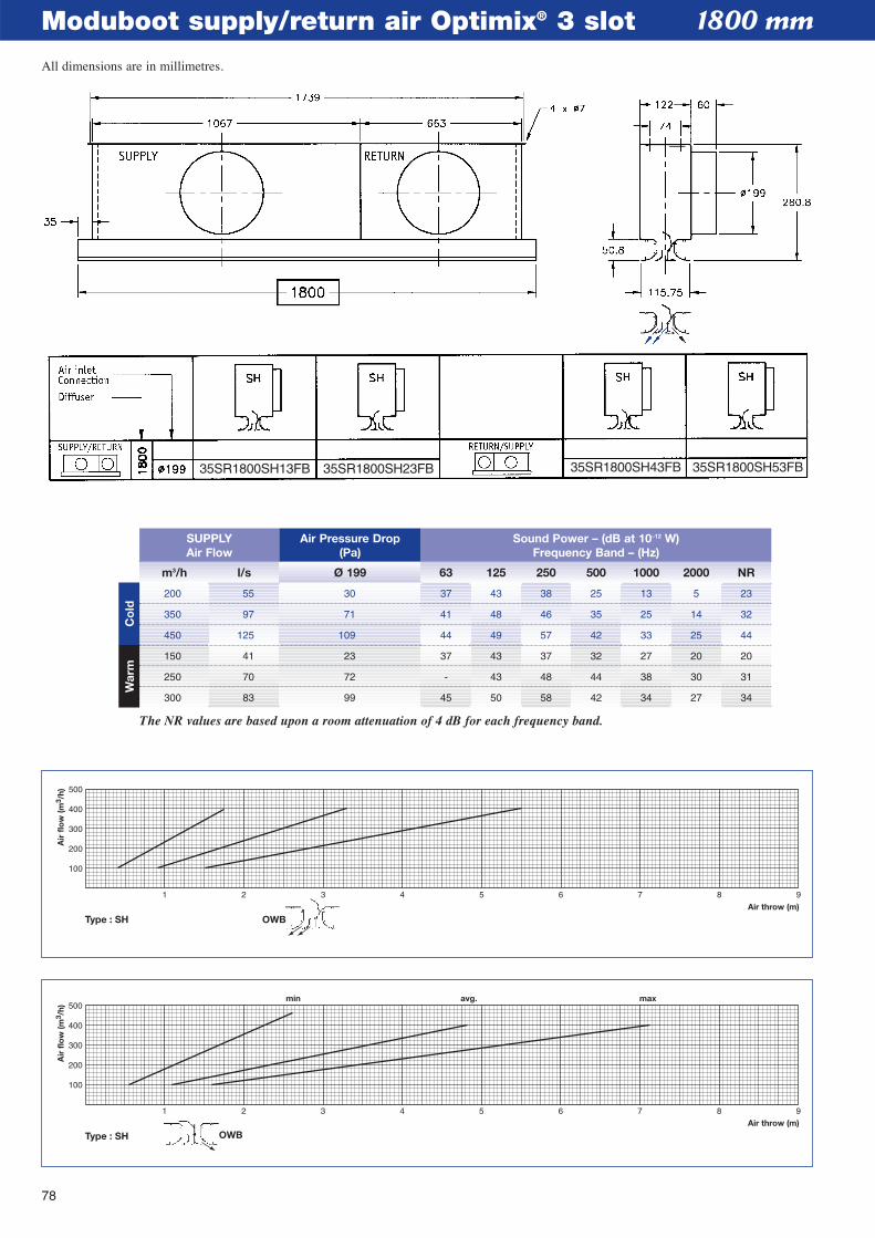
78
Moduboot supply/return air Optimix® 3 slot
1 2 3 4 5 6 7 8 9Air throw (m)
min avg. max
100
200
300
400
500
Air
flo
w (m
3 /h)
Type : SH OWB
1 2 3 4 5 6 7 8 9
100
200
300
400
500
OWBAir throw (m)
Air
flo
w (m
3 /h)
Type : SH
1800 mm
m3/h l/s Ø 199 63 125 250 500 1000 2000 NR
SUPPLYAir Flow
Air Pressure Drop(Pa)
Sound Power – (dB at 10–12 W)Frequency Band – (Hz)
200 55 30 37 43 38 25 13 5 23
350 97 71 41 48 46 35 25 14 32
450 125 109 44 49 57 42 33 25 44
150 41 23 37 43 37 32 27 20 20
250 70 72 - 43 48 44 38 30 31
300 83 99 45 50 58 42 34 27 34
The NR values are based upon a room attenuation of 4 dB for each frequency band.
Co
ldW
arm
35SR1800SH13FB 35SR1800SH23FB 35SR1800SH43FB 35SR1800SH53FB
All dimensions are in millimetres.
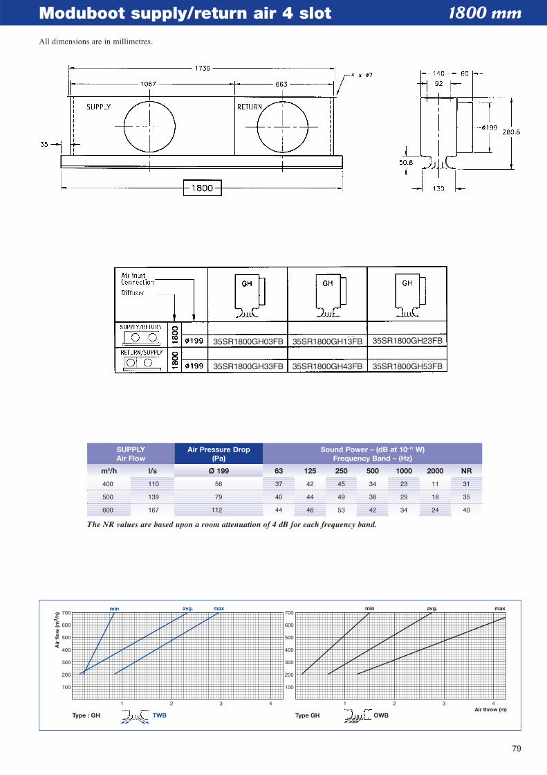
79
Moduboot supply/return air 4 slot
1 2 3 4Air throw (m)
100
200
300
400
500
600
700
100
200
300
400
500
600
700avg. max
Air
flo
w (m
3 /h)
1 2 3 4
min avg. max
Type : GH Type GHTWB OWB
min
1800 mm
m3/h l/s Ø 199 63 125 250 500 1000 2000 NR
SUPPLYAir Flow
Air Pressure Drop(Pa)
Sound Power – (dB at 10–12 W)Frequency Band – (Hz)
400 110 56 37 42 45 34 23 11 31
500 139 79 40 44 49 38 29 18 35
600 167 112 44 46 53 42 34 24 40
The NR values are based upon a room attenuation of 4 dB for each frequency band.
35SR1800GH03FB
35SR1800GH33FB
35SR1800GH13FB
35SR1800GH43FB
35SR1800GH23FB
35SR1800GH53FB
All dimensions are in millimetres.
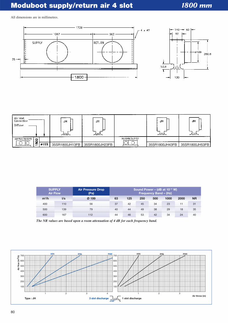
80
Moduboot supply/return air 4 slot
1 2 3 4Air throw (m)
100
200
300
400
500
600
700
100
200
300
400
500
600
700min avg. max
Air
flo
w (m
3 /h)
1 2 3
min avg. max
Type : JH 3 slot discharge 1 slot discharge
1800 mm
m3/h l/s Ø 199 63 125 250 500 1000 2000 NR
SUPPLYAir Flow
Air Pressure Drop(Pa)
Sound Power – (dB at 10–12 W)Frequency Band – (Hz)
400 110 56 37 42 45 34 23 11 31
500 139 79 40 44 49 38 29 18 35
600 167 112 44 46 53 42 34 24 40
The NR values are based upon a room attenuation of 4 dB for each frequency band.
35SR1800JH13FB 35SR1800JH23FB 35SR1800JH43FB 35SR1800JH53FB
All dimensions are in millimetres.
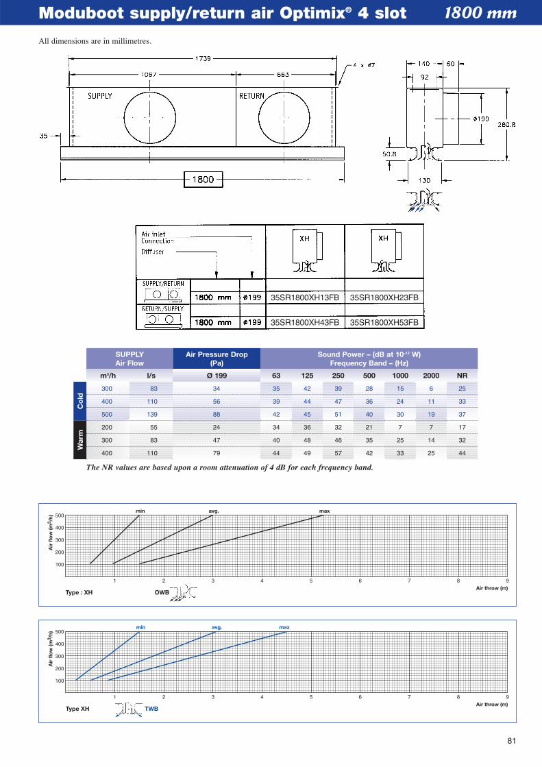
81
Moduboot supply/return air Optimix® 4 slot
1 2 3 4 5 6 7 8 9Air throw (m)
min avg. max
100
200
300
400
500
Air
flo
w (m
3 /h)
Type XH TWB
1 2 3 4 5 6 7 8 9Air throw (m)
min avg. max
100
200
300
400
500
Air
flo
w (m
3 /h)
Type : XH OWB
1800 mm
m3/h l/s Ø 199 63 125 250 500 1000 2000 NR
SUPPLYAir Flow
Air Pressure Drop(Pa)
Sound Power – (dB at 10–12 W)Frequency Band – (Hz)
300 83 34 35 42 39 28 15 6 25
400 110 56 39 44 47 36 24 11 33
500 139 88 42 45 51 40 30 19 37
200 55 24 34 36 32 21 7 7 17
300 83 47 40 48 46 35 25 14 32
400 110 79 44 49 57 42 33 25 44
The NR values are based upon a room attenuation of 4 dB for each frequency band.
Co
ldW
arm
35SR1800XH13FB 35SR1800XH23FB
35SR1800XH43FB 35SR1800XH53FB
All dimensions are in millimetres.
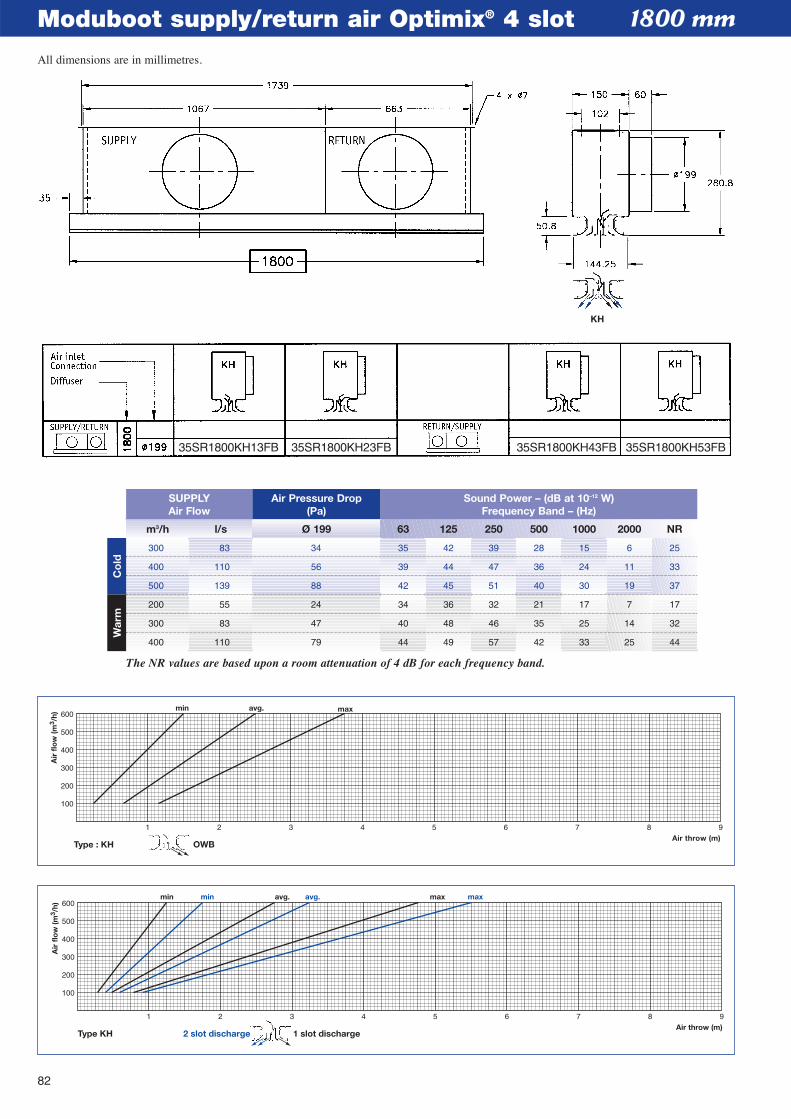
82
Moduboot supply/return air Optimix® 4 slot
1 2 3 4 5 6 7 8 9Air throw (m)
min avg. maxmin avg. max
100
200
300
400
500
600
Air
flo
w (m
3 /h)
Type KH 1 slot discharge2 slot discharge
1 2 3 4 5 6 7 8 9
100
200
300
400
500
600min avg. max
Type : KH
Air
flo
w (m
3 /h)
Air throw (m)OWB
1800 mm
m3/h l/s Ø 199 63 125 250 500 1000 2000 NR
SUPPLYAir Flow
Air Pressure Drop(Pa)
Sound Power – (dB at 10–12 W)Frequency Band – (Hz)
300 83 34 35 42 39 28 15 6 25
400 110 56 39 44 47 36 24 11 33
500 139 88 42 45 51 40 30 19 37
200 55 24 34 36 32 21 17 7 17
300 83 47 40 48 46 35 25 14 32
400 110 79 44 49 57 42 33 25 44
The NR values are based upon a room attenuation of 4 dB for each frequency band.
Co
ldW
arm
KH
35SR1800KH13FB 35SR1800KH23FB 35SR1800KH43FB 35SR1800KH53FB
All dimensions are in millimetres.
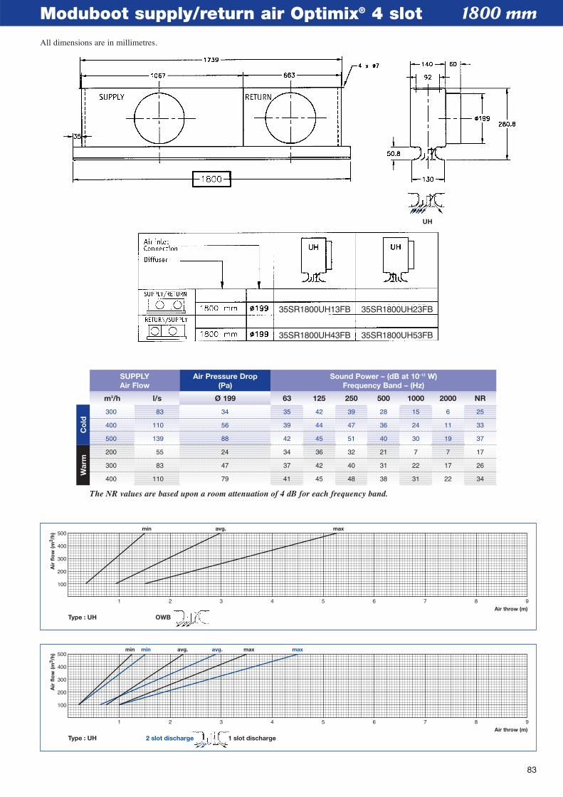
83
Moduboot supply/return air Optimix® 4 slot
1 2 3 4 5 6 7 8 9Air throw (m)
min avg. maxmin avg. max
100
200
300
400
500
Air
flo
w (m
3 /h)
Type : UH 1 slot discharge2 slot discharge
1 2 3 4 5 6 7 8 9Air throw (m)
min avg. max
100
200
300
400
500
Air
flo
w (m
3 /h)
Type : UH OWB
1800 mm
m3/h l/s Ø 199 63 125 250 500 1000 2000 NR
SUPPLYAir Flow
Air Pressure Drop(Pa)
Sound Power – (dB at 10–12 W)Frequency Band – (Hz)
300 83 34 35 42 39 28 15 6 25
400 110 56 39 44 47 36 24 11 33
500 139 88 42 45 51 40 30 19 37
200 55 24 34 36 32 21 7 7 17
300 83 47 37 42 40 31 22 17 26
400 110 79 41 45 48 38 31 22 34
The NR values are based upon a room attenuation of 4 dB for each frequency band.
Co
ldW
arm
UH
35SR1800UH13FB 35SR1800UH23FB
35SR1800UH43FB 35SR1800UH53FB
All dimensions are in millimetres.
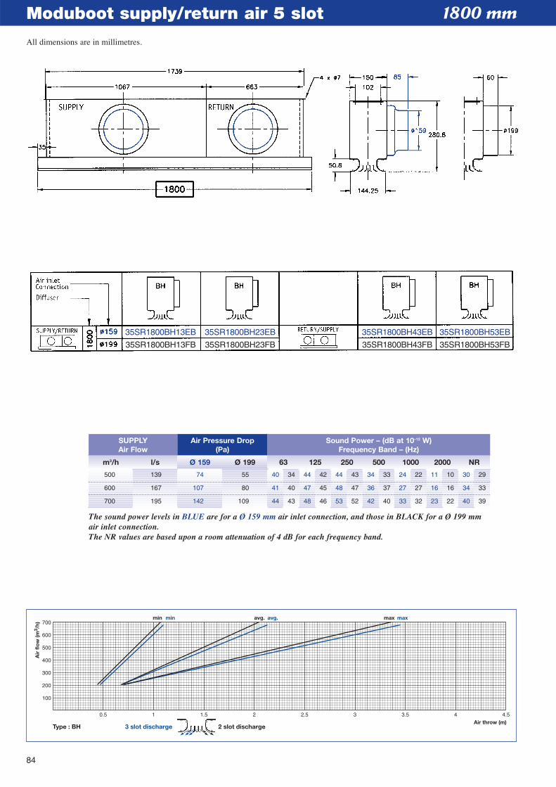
84
Moduboot supply/return air 5 slot
0.5 1 1.5 2 2.5 3 3.5 4 4.5Air throw (m)
minmin avg.avg. maxmax
100
200
300
400
500
600
700
Air
flo
w (m
3 /h)
Type : BH 3 slot discharge 2 slot discharge
1800 mm
m3/h l/s Ø 159 Ø 199 63 125 250 500 1000 2000 NR
SUPPLYAir Flow
Air Pressure Drop(Pa)
Sound Power – (dB at 10–12 W)Frequency Band – (Hz)
500 139 74 55 40 34 44 42 44 43 34 33 24 22 11 10 30 29
600 167 107 80 41 40 47 45 48 47 36 37 27 27 16 16 34 33
700 195 142 109 44 43 48 46 53 52 42 40 33 32 23 22 40 39
The sound power levels in BLUE are for a Ø 159 mm air inlet connection, and those in BLACK for a Ø 199 mmair inlet connection.The NR values are based upon a room attenuation of 4 dB for each frequency band.
35SR1800BH13EB
35SR1800BH13FB
35SR1800BH23EB
35SR1800BH23FB
35SR1800BH43EB
35SR1800BH43FB
35SR1800BH53EB
35SR1800BH53FB
All dimensions are in millimetres.
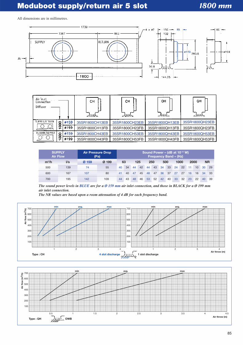
85
Moduboot supply/return air 5 slot
0.5 1 1.5 2 2.5 3 3.5 4 4.5Air throw (m)
min avg. max
100
200
300
400
500
600
700
Air
flo
w (m
3 /h)
Type : QH OWB
1 2 3 4Air throw (m)
100
200
300
400
500
600
700
100
200
300
400
500
600
700
Air
flo
w (m
3 /h)
1 2 3 4
min avg. maxmin avg. max
Type : CH 4 slot discharge 1 slot discharge
1800 mm
m3/h l/s Ø 159 Ø 199 63 125 250 500 1000 2000 NR
SUPPLYAir Flow
Air Pressure Drop(Pa)
Sound Power – (dB at 10–12 W)Frequency Band – (Hz)
500 139 74 55 40 34 44 42 44 43 34 33 24 22 11 10 30 29
600 167 107 80 41 40 47 45 48 47 36 37 27 27 16 16 34 33
700 195 142 109 44 43 48 46 53 52 42 40 33 32 23 22 40 39
The sound power levels in BLUE are for a Ø 159 mm air inlet connection, and those in BLACK for a Ø 199 mmair inlet connection.The NR values are based upon a room attenuation of 4 dB for each frequency band.
35SR1800CH13EB
35SR1800CH13FB
35SR1800CH43EB
35SR1800CH43FB
35SR1800CH23EB
35SR1800CH23FB
35SR1800CH53EB
35SR1800CH53FB
35SR1800QH13EB
35SR1800QH13FB
35SR1800QH43EB
35SR1800QH43FB
35SR1800QH23EB
35SR1800QH23FB
35SR1800QH53EB
35SR1800QH53FB
All dimensions are in millimetres.
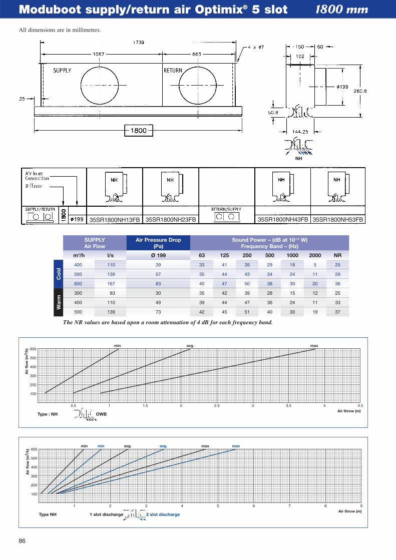
86
Moduboot supply/return air Optimix® 5 slot
1 2 3 4 5 6 7 8 9Air throw (m)
min avg.min avg. max max
100
200
300
400
500
600
Air
flo
w (m
3 /h)
Type NH 2 slot discharge1 slot discharge
Air throw (m)
min avg. max
100
200
300
400
500
600
Air
flo
w (m
3 /h)
0.5 1 1.5 2 2.5 3 3.5 4 4.5
Type : NH OWB
1800 mm
m3/h l/s Ø 199 63 125 250 500 1000 2000 NR
SUPPLYAir Flow
Air Pressure Drop(Pa)
Sound Power – (dB at 10–12 W)Frequency Band – (Hz)
400 110 39 33 41 39 29 18 5 25
500 139 57 35 44 43 34 24 11 29
600 167 83 40 47 50 38 30 20 36
300 83 30 35 42 39 28 15 12 25
400 110 49 39 44 47 36 24 11 33
500 139 73 42 45 51 40 30 19 37
The NR values are based upon a room attenuation of 4 dB for each frequency band.
Co
ldW
arm
NH
35SR1800NH13FB 35SR1800NH23FB 35SR1800NH43FB 35SR1800NH53FB
All dimensions are in millimetres.
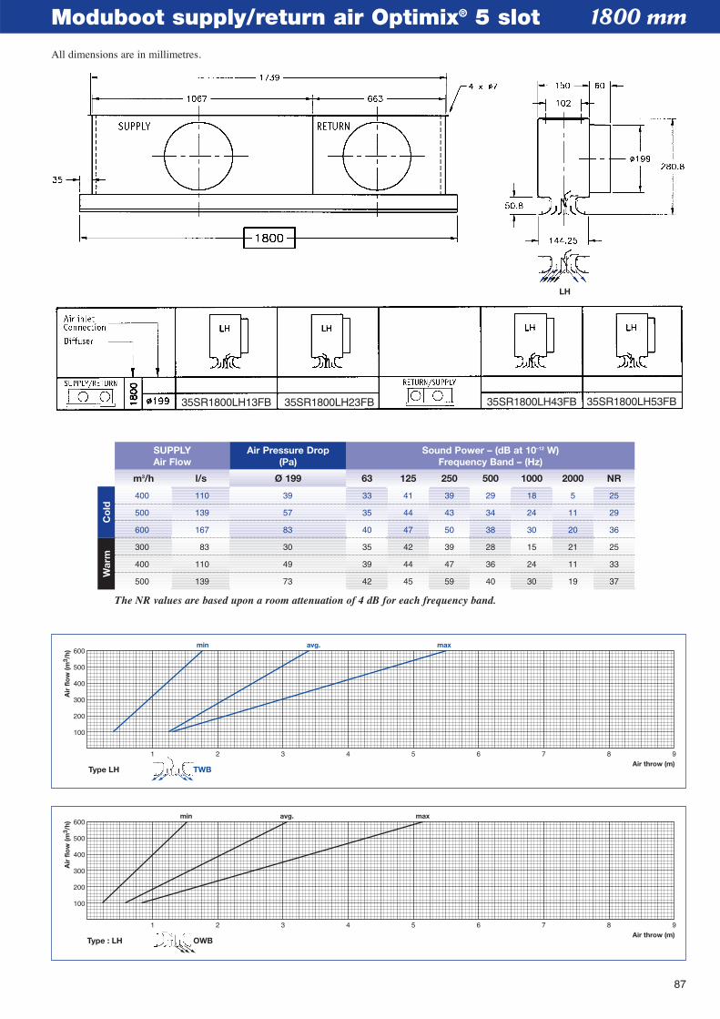
87
Moduboot supply/return air Optimix® 5 slot
1 2 3 4 5 6 7 8 9Air throw (m)
min avg. max
100
200
300
400
500
600
Air
flo
w (m
3 /h)
Type : LH OWB
1 2 3 4 5 6 7 8 9Air throw (m)
min avg. max
100
200
300
400
500
600
Air
flo
w (m
3 /h)
Type LH TWB
1800 mm
m3/h l/s Ø 199 63 125 250 500 1000 2000 NR
SUPPLYAir Flow
Air Pressure Drop(Pa)
Sound Power – (dB at 10–12 W)Frequency Band – (Hz)
400 110 39 33 41 39 29 18 5 25
500 139 57 35 44 43 34 24 11 29
600 167 83 40 47 50 38 30 20 36
300 83 30 35 42 39 28 15 21 25
400 110 49 39 44 47 36 24 11 33
500 139 73 42 45 59 40 30 19 37
The NR values are based upon a room attenuation of 4 dB for each frequency band.
Co
ldW
arm
LH
35SR1800LH13FB 35SR1800LH23FB 35SR1800LH43FB 35SR1800LH53FB
All dimensions are in millimetres.
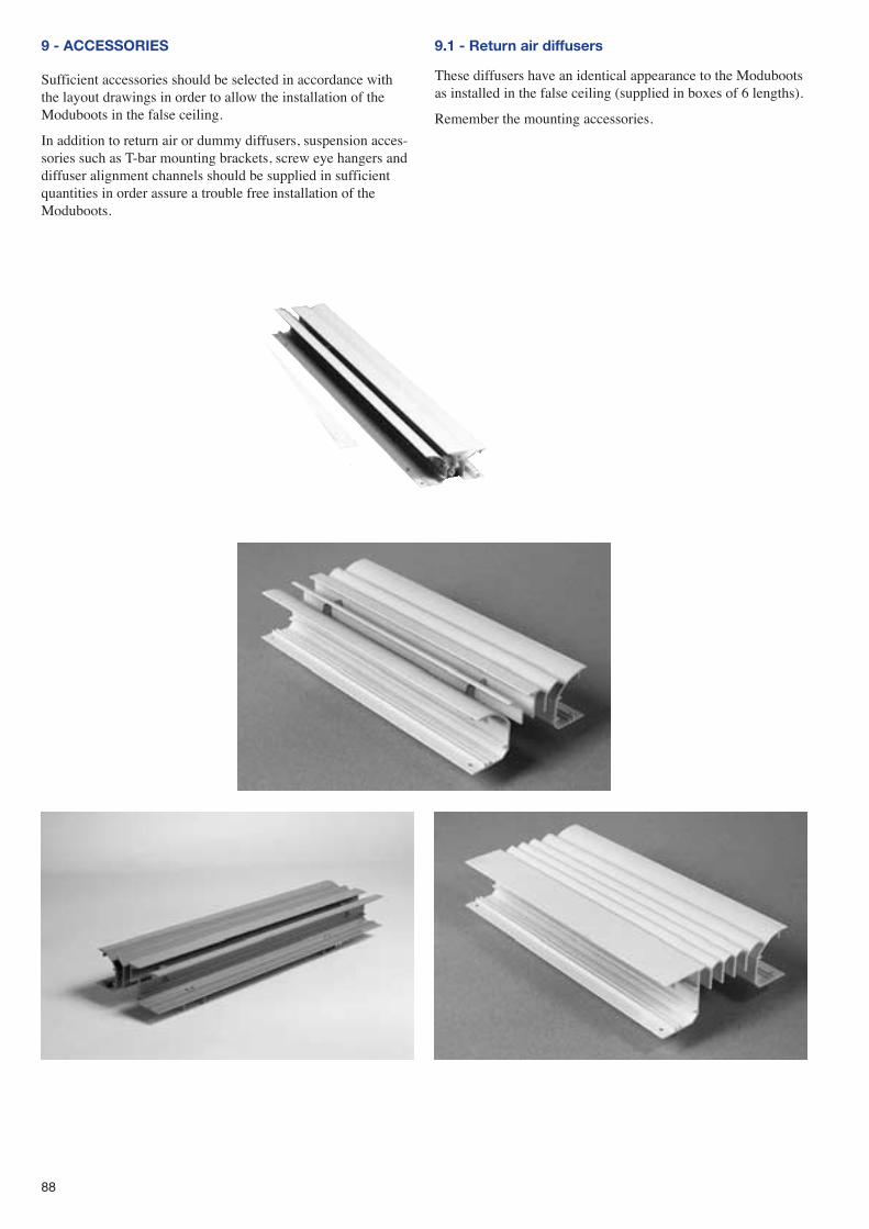
9 - ACCESSORIES
Sufficient accessories should be selected in accordance withthe layout drawings in order to allow the installation of theModuboots in the false ceiling.
In addition to return air or dummy diffusers, suspension acces-sories such as T-bar mounting brackets, screw eye hangers anddiffuser alignment channels should be supplied in sufficientquantities in order assure a trouble free installation of theModuboots.
9.1 - Return air diffusers
These diffusers have an identical appearance to the Modubootsas installed in the false ceiling (supplied in boxes of 6 lengths).
Remember the mounting accessories.
88
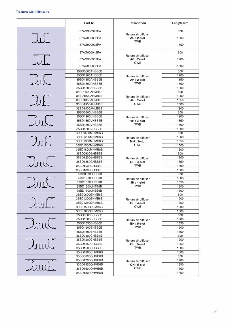
89
NtraP ° noitpircseD mmhtgneL
PA229009GA73
PA228009GA73
PA220009GA73
resuffidrianruteRtols-2:GA
BWT
006
0021
0051
PA249009GA73
PA209009GA73
PA288009GA73
resuffidrianruteRtols-2:GA
BWO
006
0021
0051
B6BBHA0060DB53
resuffidrianruteRtols-2:HA
BWT
006B6BBHA0021DB53 0021B6BBHA0531DB53 0531B6BBHA0051DB53 0051B6BBHA0081DB53 0081B6BMHA0060DB53
resuffidrianruteRtols-2:HA
BWO
006B6BMHA0021DB53 0021B6BMHA0531DB53 0531B6BMHA0051DB53 0051B6BMHA0081DB53 0081B6BBHV0060DB53
resuffidrianruteRtols-3:HV
BWT
006B6BBHV0021DB53 0021B6BBHV0531DB53 0531B6BBHV0051DB53 0051B6BBHV0081DB53 0081B6BMHM0060DB53
resuffidrianruteRtols-3:HM
BWO
006B6BMHM0021DB53 0021B6BMHM0531DB53 0531B6BMHM0051DB53 0051B6BMHM0081DB53 0081B6BBHG0060DB53
resuffidrianruteRtols-4:HG
BWT
006B6BBHG0021DB53 0021B6BBHG0531DB53 0531B6BBHG0051DB53 0051B6BBHG0081DB53 0081B6BBHJ0060DB53
resuffidrianruteRtols-4:HJ
BWT
006B6BBHJ0021DB53 0021B6BBHJ0531DB53 0531B6BBHJ0051DB53 0051B6BBHJ0081DB53 0081B6BMHG0060DB53
resuffidrianruteRtols-4:HG
BWO
006B6BMHG0021DB53 0021B6BMHG0531DB53 0531B6BMHG0051DB53 0051B6BMHG0081DB53 0081B6BBHB0060DB53
resuffidrianruteRtols-5:HB
BWT
006B6BBHB0021DB53 0021B6BBHB0531DB53 0531B6BBHB0051DB53 0051B6BBHB0081DB53 0081B6BBHC0060DB53
resuffidrianruteRtols-5:HC
BWT
006B6BBHC0021DB53 0021B6BBHC0531DB53 0531B6BBHC0051DB53 0051B6BMHC0081DB53 0081B6BMHQ0060DB53
resuffidrianruteRtols-5:HQ
BWO
006B6BMHQ0021DB53 0021B6BMHQ0531DB53 0531B6BMHQ0051DB53 0051B6BMHQ0081DB53 0081
Return air diffusers
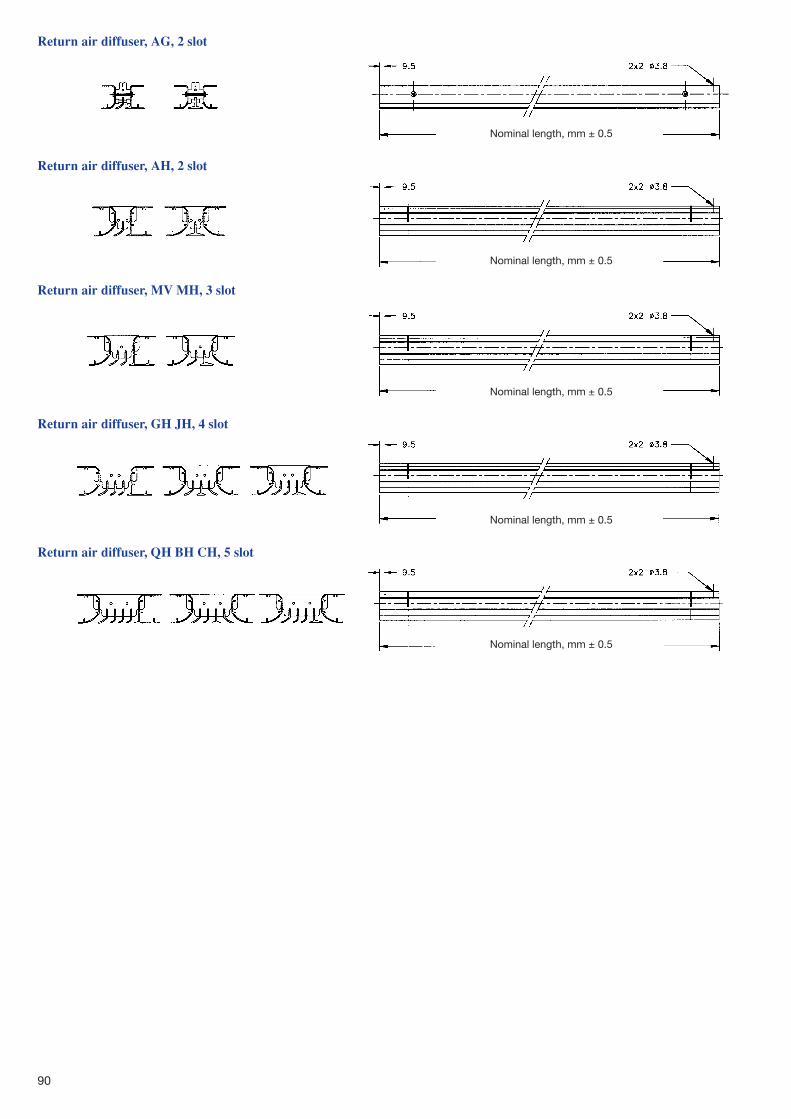
90
Return air diffuser, AG, 2 slot
Return air diffuser, AH, 2 slot
Return air diffuser, MV MH, 3 slot
Return air diffuser, GH JH, 4 slot
Return air diffuser, QH BH CH, 5 slot
Nominal length, mm ± 0.5
Nominal length, mm ± 0.5
Nominal length, mm ± 0.5
Nominal length, mm ± 0.5
Nominal length, mm ± 0.5
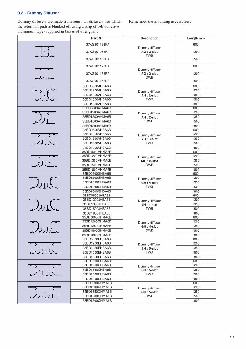
91
9.2 - Dummy Diffuser
Dummy diffusers are made from return air diffusers, for whichthe return air path is blanked off using a strip of self adhesivealuminium tape (supplied in boxes of 6 lengths).
Remember the mounting accessories.
NtraP ° noitpircseD mmhtgneL
PA291109GA73
PA280109GA73
PA201109GA73
resuffidymmuDtols-2:GA
BWT
006
0021
0051
PA271109GA73
PA231109GA73
PA251109GA73
resuffidymmuDtols-2:GA
BWO
006
0021
0051
B6ABHA0060DB53
resuffidymmuDtols-2:HA
BWT
006B6ABHA0021DB53 0021B6ABHA0531DB53 0531B6ABHA0051DB53 0051B6ABHA0081DB53 0081B6AMHA0060DB53
resuffidymmuDtols-2:HA
BWO
006B6AMHA0021DB53 0021B6AMHA0531DB53 0531B6AMHA0051DB53 0051B6AMHA0081DB53 0081B6ABHV0060DB53
resuffidymmuDtols-3:HV
BWT
006B6ABHV0021DB53 0021B6ABHV0531DB53 0531B6ABHV0051DB53 0051B6ABHV0081DB53 0081B6AMHM0060DB53
resuffidymmuDtols-3:HM
BWO
006B6AMHM0021DB53 0021B6AMHM0531DB53 0531B6AMHM0051DB53 0051B6AMHM0081DB53 0081B6ABHG0060DB53
resuffidymmuDtols-4:HG
BWT
006B6ABHG0021DB53 0021B6ABHG0531DB53 0531B6ABHG0051DB53 0051B6ABHG0081DB53 0081B6ABHJ0060DB53
resuffidymmuDtols-4:HJ
BWT
006B6ABHJ0021DB53 0021B6ABHJ0531DB53 0531B6ABHJ0051DB53 0051B6ABHJ0081DB53 0081B6AMHG0060DB53
resuffidymmuDtols-4:HG
BWO
006B6AMHG0021DB53 0021B6AMHG0531DB53 0531B6AMHG0051DB53 0051B6AMHG0081DB53 0081B6ABHB0060DB53
resuffidymmuDtols-5:HB
BWT
006B6ABHB0021DB53 0021B6ABHB0531DB53 0531B6ABHB0051DB53 0051B6ABHB0081DB53 0081B6ABHC0060DB53
resuffidymmuDtols-5:HC
BWT
006B6ABHC0021DB53 0021B6ABHC0531DB53 0531B6ABHC0051DB53 0051B6ABHC0081DB53 0081B6AMHQ0060DB53
resuffidymmuDtols-5:HQ
BWO
006B6AMHQ0021DB53 0021B6AMHQ0531DB53 0531B6AMHQ0051DB53 0051B6AMHQ0081DB53 0081
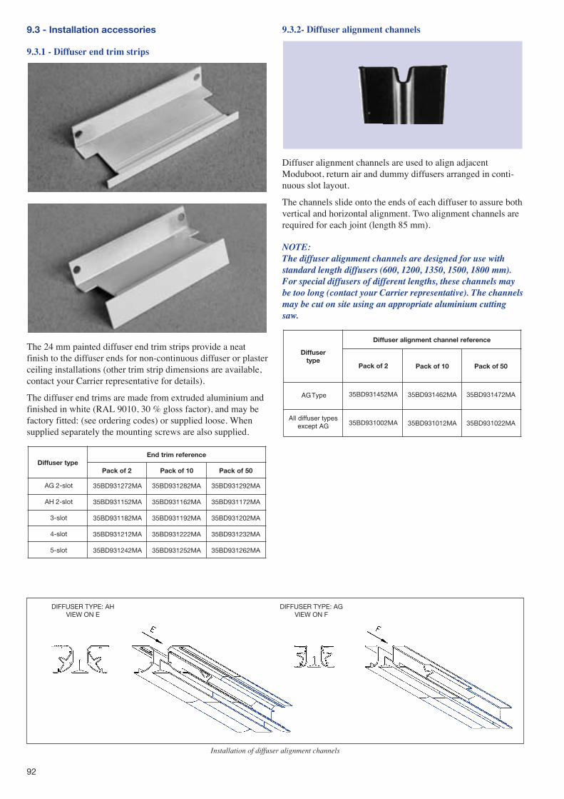
92
9.3 - Installation accessories
9.3.1 - Diffuser end trim strips
The 24 mm painted diffuser end trim strips provide a neatfinish to the diffuser ends for non-continuous diffuser or plasterceiling installations (other trim strip dimensions are available,contact your Carrier representative for details).
The diffuser end trims are made from extruded aluminium andfinished in white (RAL 9010, 30 % gloss factor), and may befactory fitted: (see ordering codes) or supplied loose. Whensupplied separately the mounting screws are also supplied.
epytresuffiDecnerefermirtdnE
Pack of 2 Pack of 10 50fokcaP
35BD931272MA
35BD931152MA
35BD931182MA
35BD931212MA
35BD931242MA
AG 2-slot
AH 2-slot
3-slot
4-slot
5-slot
35BD931282MA
35BD931162MA
35BD931192MA
35BD931222MA
35BD931252MA
35BD931292MA
35BD931172MA
35BD931202MA
35BD931232MA
35BD931262MA
9.3.2- Diffuser alignment channels
Diffuser alignment channels are used to align adjacentModuboot, return air and dummy diffusers arranged in conti-nuous slot layout.
The channels slide onto the ends of each diffuser to assure bothvertical and horizontal alignment. Two alignment channels arerequired for each joint (length 85 mm).
NOTE:The diffuser alignment channels are designed for use withstandard length diffusers (600, 1200, 1350, 1500, 1800 mm).For special diffusers of different lengths, these channels maybe too long (contact your Carrier representative). The channelsmay be cut on site using an appropriate aluminium cuttingsaw.
resuffiDepyt
ecnereferlennahctnemngilaresuffiD
Pack of 2
35BD931452MA
35BD931002MA
epyTAG
sepytresuffidllAGAtpecxe
Pack of 10
35BD931462MA
35BD931012MA
Pack of 50
35BD931472MA
35BD931022MA
Installation of diffuser alignment channels
DIFFUSER TYPE: AHVIEW ON E
DIFFUSER TYPE: AGVIEW ON F
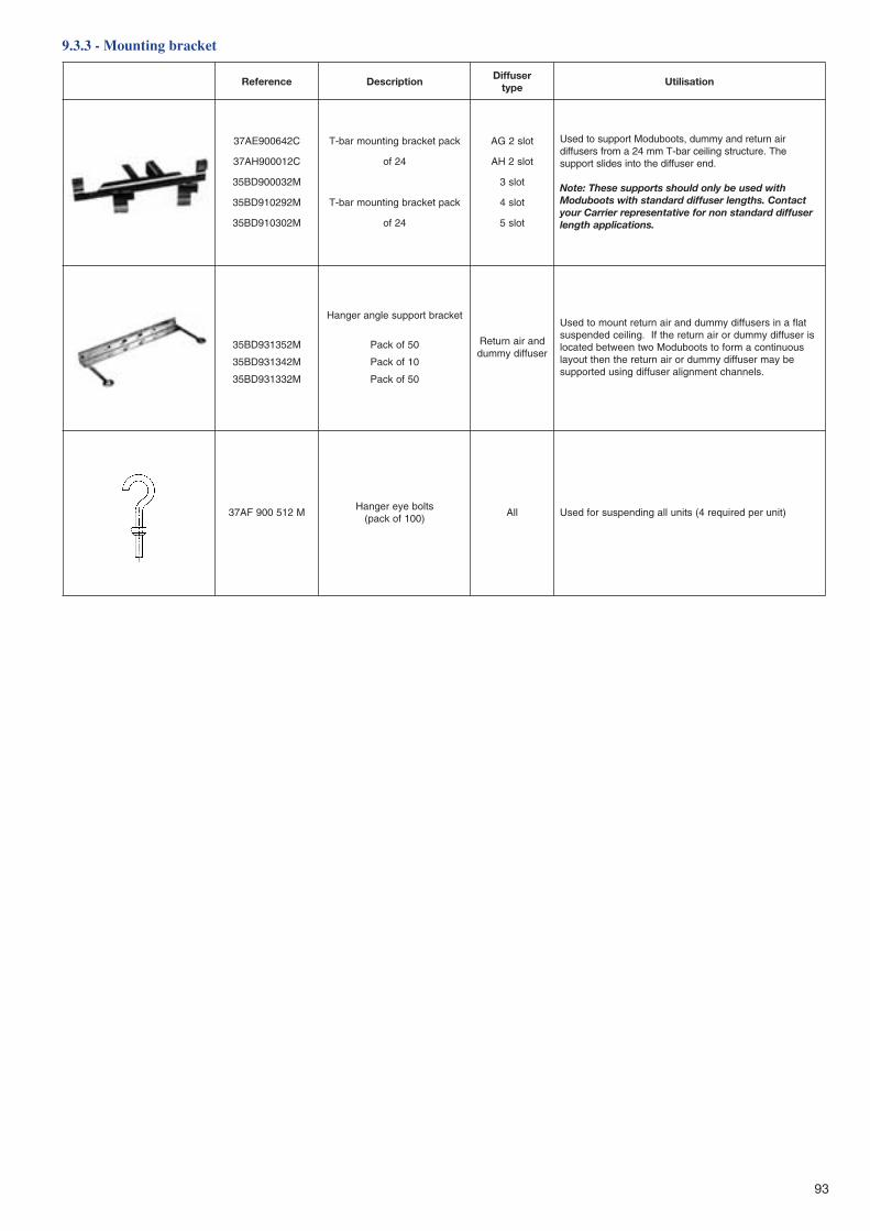
93
ecnerefeR noitpircseDresuffiD
epytnoitasilitU
C246009EA73
C210009HA73
M230009DB53
M292019DB53
M203019DB53
kcaptekcarbgnitnuomrab-T
42fo
kcaptekcarbgnitnuomrab-T
42fo
tols2GA
tols2HA
tols3
tols4
tols5
rianruterdnaymmud,stoobudoMtroppusotdesUehT.erutcurtsgniliecrab-Tmm42amorfsresuffid
.dneresuffidehtotnisedilstroppus
htiwdesuebylnodluohsstroppusesehT:etoNtcatnoC.shtgnelresuffiddradnatshtiwstoobudoMresuffiddradnatsnonrofevitatneserperreirraCruoy
.snoitacilppahtgnel
M253139DB53
M243139DB53
M233139DB53
tekcarbtroppuselgnaregnaH
05fokcaP
01fokcaP
05fokcaP
dnarianruteRresuffidymmud
talfanisresuffidymmuddnarianrutertnuomotdesUsiresuffidymmudrorianruterehtfI.gniliecdednepsus
suounitnocamrofotstoobudoMowtneewtebdetacolebyamresuffidymmudrorianruterehtnehttuoyal
.slennahctnemngilaresuffidgnisudetroppus
M215009FA73stlobeyeregnaH
)001fokcap(llA )tinurepderiuqer4(stinullagnidnepsusrofdesU
9.3.3 - Mounting bracket
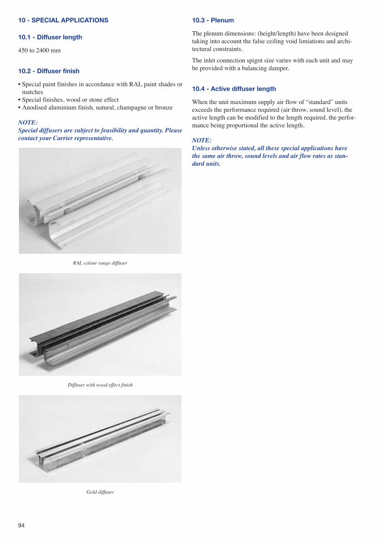
94
10 - SPECIAL APPLICATIONS
10.1 - Diffuser length
450 to 2400 mm
10.2 - Diffuser finish
� Special paint finishes in accordance with RAL paint shades ormatches
� Special finishes, wood or stone effect� Anodised aluminium finish, natural, champagne or bronze
NOTE:Special diffusers are subject to feasibility and quantity. Pleasecontact your Carrier representative.
RAL colour range diffuser
Diffuser with wood effect finish
Gold diffuser
10.3 - Plenum
The plenum dimensions: (height/length) have been designedtaking into account the false ceiling void limiations and archi-tectural constraints.
The inlet connection spigot size varies with each unit and maybe provided with a balancing damper.
10.4 - Active diffuser length
When the unit maximum supply air flow of �standard� unitsexceeds the performance required (air throw, sound level), theactive length can be modified to the length required, the perfor-mance being proportional the active length.
NOTE:Unless otherwise stated, all these special applications havethe same air throw, sound levels and air flow rates as stan-dard units.
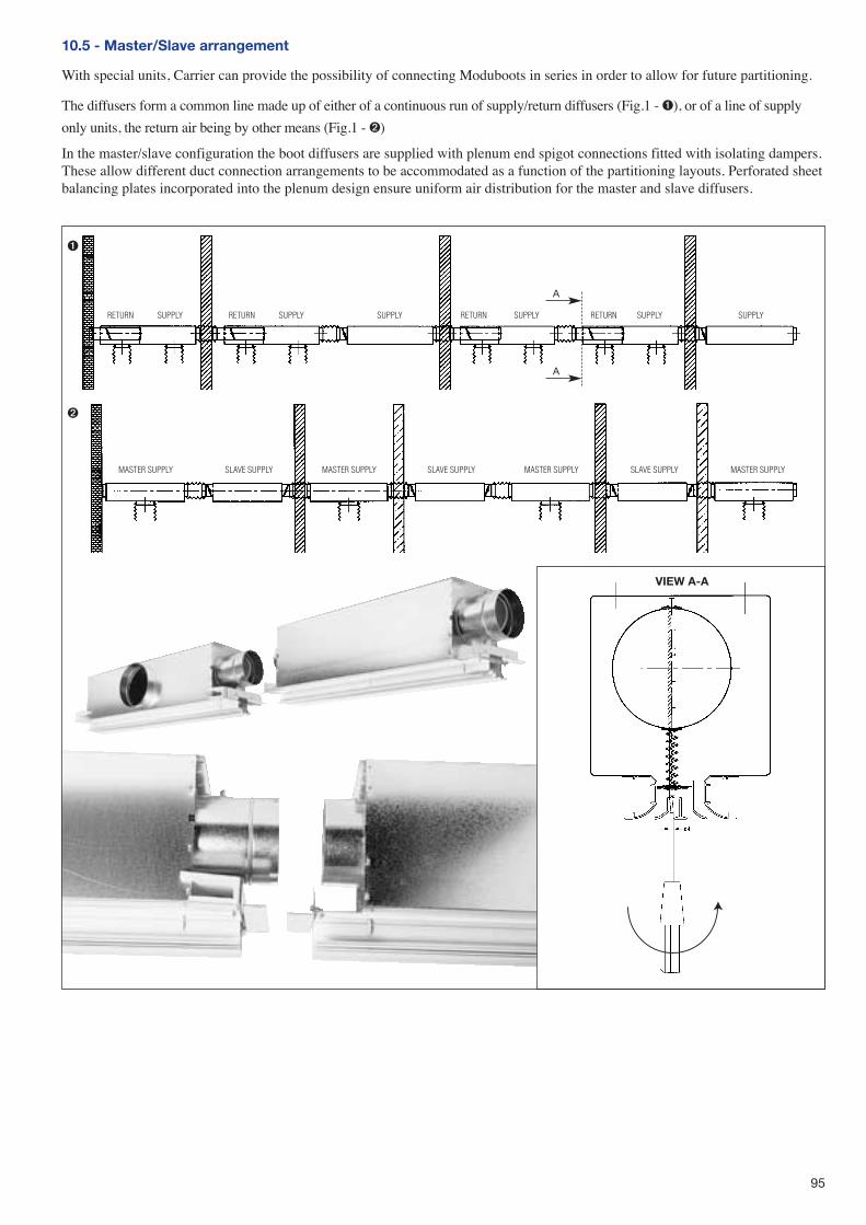
95
10.5 - Master/Slave arrangement
With special units, Carrier can provide the possibility of connecting Moduboots in series in order to allow for future partitioning.
The diffusers form a common line made up of either of a continuous run of supply/return diffusers (Fig.1 - ➊), or of a line of supply
only units, the return air being by other means (Fig.1 - ➋)
In the master/slave configuration the boot diffusers are supplied with plenum end spigot connections fitted with isolating dampers.These allow different duct connection arrangements to be accommodated as a function of the partitioning layouts. Perforated sheetbalancing plates incorporated into the plenum design ensure uniform air distribution for the master and slave diffusers.
A
A
RETURN RETURN RETURN RETURNSUPPLY
SLAVE SUPPLYMASTER SUPPLY SLAVE SUPPLY SLAVE SUPPLYMASTER SUPPLY MASTER SUPPLY MASTER SUPPLY
SUPPLY SUPPLY SUPPLY SUPPLY SUPPLY
➊
➋
VIEW A-A
Order No.: 13502-20, 03.2005 - Supersedes order No.: 13502-20, 02.2004.Manufacturer reserves the right to change any product specification without notice.
Manufacturer: Carrier s.a., Montluel, France.Printed in the Netherlands.
11 - GUIDE SPECIFICATIONS
Supply and install
The Moduboot diffusers shall be selected in accordance withthe required performance and architectural constraints (falseceiling type, appearance, etc...)
Based on the information shown on the drawings, sufficientaccessories shall be supplied, to allow the base units to func-tion properly. Additionally return air diffuser, dummy diffuserand diffuser end trim pieces shall be supplied as necessary. Theaccessories such as T-bar mounting brackets, hanger eye boltsand diffuser alignment channels shall be supplied in sufficientquantities to provide a complete installation.
Moduboot Plenum
Plenums shall be made from 6/10 mm galvanised sheet steeland internally lined with 13 mm medium density fibre wool(minimum 24 kg/m3) which is protected with a neoprene skinto avoid any risk of erosion. This fibre wool provides both ther-mal and acoustical insulation.
Air Diffuser
The diffusers shall linear type with high induction rates.Diffusers shall be of extruded aluminium with a white ovenbaked epoxy paint finish (RAL 9010, 30% gloss factor) inaccordance with the QUALICOAT standard.
Painted diffusers shall be protected by a pealable adhesivestrip, to be removed after installation.
The high induction rate diffusers shall operate from 100 to 15 %of nominal air flow in both cooling and heating modes (for tem-perature differences of up to 14 K) without loss of air flow per-formance. This performance data shall be based upon labora-tory tests and published catalogue data. For conditioned spacesof up to 3 m in height, the diffuser shall maintain the requestedtemperature to ± 1 K in the occupied zone, whilst maintainingthe air velocity distribution below the values recommended bythe main comfort standards in effect.
Carrier S.A.S. Demonstration SuiteWhether you live in the tropics or in Greenland
Whether you suffer from the heat, from the cold or from lack of airCARRIER has the solution and can show it to you in the demonstration suite
The programmes available
✔✔ simulation of the climate in your region
✔✔ simulation of the heating and cooling loads according toyour needs
✔✔ measuring, storing and display of the air temperaturesand the air distribution pattern taking into account yourclimatic and architectural constraints - even at climaticextremes
✔✔ optimisation of the physical location of the air terminalsin your building walls or ceilings
✔✔ determination and control of the sound level in everyroom
✔✔ simulation of the control system of your terminals and their link to your BMS system
✔✔ and finally, simulation of how your interior will look, with a floor plan, lights and blinds to ensure true quality
Experience a real preview of your future installation