360b labwindows user's guide - top dog test · limited warranty the media on which you receive...
TRANSCRIPT
You wil l be asked for this number when youcal l Wil tron Customer Service for support .
Serial Number
P/N: 10570-00002REVISION A:
PRINTED: MARCH 1993COPYRIGHT 1993 WILTRON COMPANY
Model 360BVector Network Analyzer
Instrument Driverfor LabWindows
User’s GuideVersion 1.00
Limited Warranty
The media on which you receive Wiltron Company software arewarranted not to fail to execute programming instructions, dueto defects in materials and workmanship, for a period of 90days from date of shipment, as evidenced by receipts or otherdocumentation. Wiltron Company will, at its option repair or re-place software media that do not execute programming instruc-tions if Wiltron Company receives notice of such defects duringthe warranty period. Wiltron Company does not warrant thatthe operation of the software shall be uninterrupted or errorfree.
EXCEPT AS SPECIFIED HEREIN, WILTRON COMPANYMAKE NO WARRANTIES, EXPRESS OR IMPLIED, AND SPE-CIFICALLY DISCLAIMS ANY WARRANTY OF MERCHANT-ABILITY OR FITNESS FOR A PARTICULAR PURPOSE.CUSTOMER’S RIGHT TO RECOVER DAMAGES CAUSED BYFAULT OR NEGLIGENCE ON THE PART OF WILTRON COM-PANY SHALL BE LIMITED TO THE AMOUNT THERETO-FORE PAID BY THE CUSTOMER. WILTRON COMPANYWILL NOT BE LIABLE FOR DAMAGES RESULTING FROMLOSS OF DATA, PROFITS, USE OF PRODUCTS, OR INCIDEN-TAL OR CONSEQUENTIAL DAMAGES, EVEN IF ADVISEDOF THE POSSIBILITY THEREOF.
The aforestated limitation of the liability of Wiltron Companywill apply regardless of the form or action, whether in contractor tort, including negligence. Any action against Wiltron Com-pany must be brought within one year after the cause of actionaccrues. Wiltron Company shall not be liable for any delay inperformance due to causes beyond its reasonable control. Thewarranty provided herein does not cover damages, defects, mal-functions, or service failures caused by owner’s abuse, misuse,or negligence acts; and power failure or surges, fire, flood, acci-dent, actions or third parties, or other events outside reason-able control.

Copyright
Under the copyright laws, this book may not be copied, photocopied, reproduced, trans-lated — in whole or in part — without the written consent of WILTRON Company.
Copyright 1993 WILTRON Company
Trademarks
LabWindows is a registered trademark of National Instruments Corporation
IBM is a registered trademark of International Business Machines Corporation. Per-sonal System/2, IBM PC, PC AT, PC/XT, PC DOS, IBM CGA, IBM EGA, IBM VGA, andMicro Channel are trademarks of International Business Machines Corporation.
Microsoft, Microsoft QuickBASIC, Microsoft BASIC, Microsoft Visual BASIC, andMicrosoft C are trademarks of Microsoft Corporation.
Preface
The 360B LabWindows Instrument Driver User’s Guide provides a tutorial and bothgeneral and detailed descriptions of the various functional panels displayed in the LabWindows environment. The user should be familiar with measurements using theapplicable WILTRON instrument and with MS- or PC-DOS conventions. A knowledge ofLabWindows, while helpful, is not essential. The WILTRON Instrument Drivers soft-ware can be used to create executable stand-alone application programs.
Manual Organization
The manual is divided into three sections:
Section 1, General, provides general information and a tree structure for the Instru-ment Driver function panels.
Section 2, Using the 360B Driver with LabWindows, provides description and a tutorialfor using the driver within the LabWindows environment.
Section 3, Driver References, provides detailed descriptions of the function panels andinstrument controls. It also provides sample syntax and a listing of variable-type usedin the program.
i
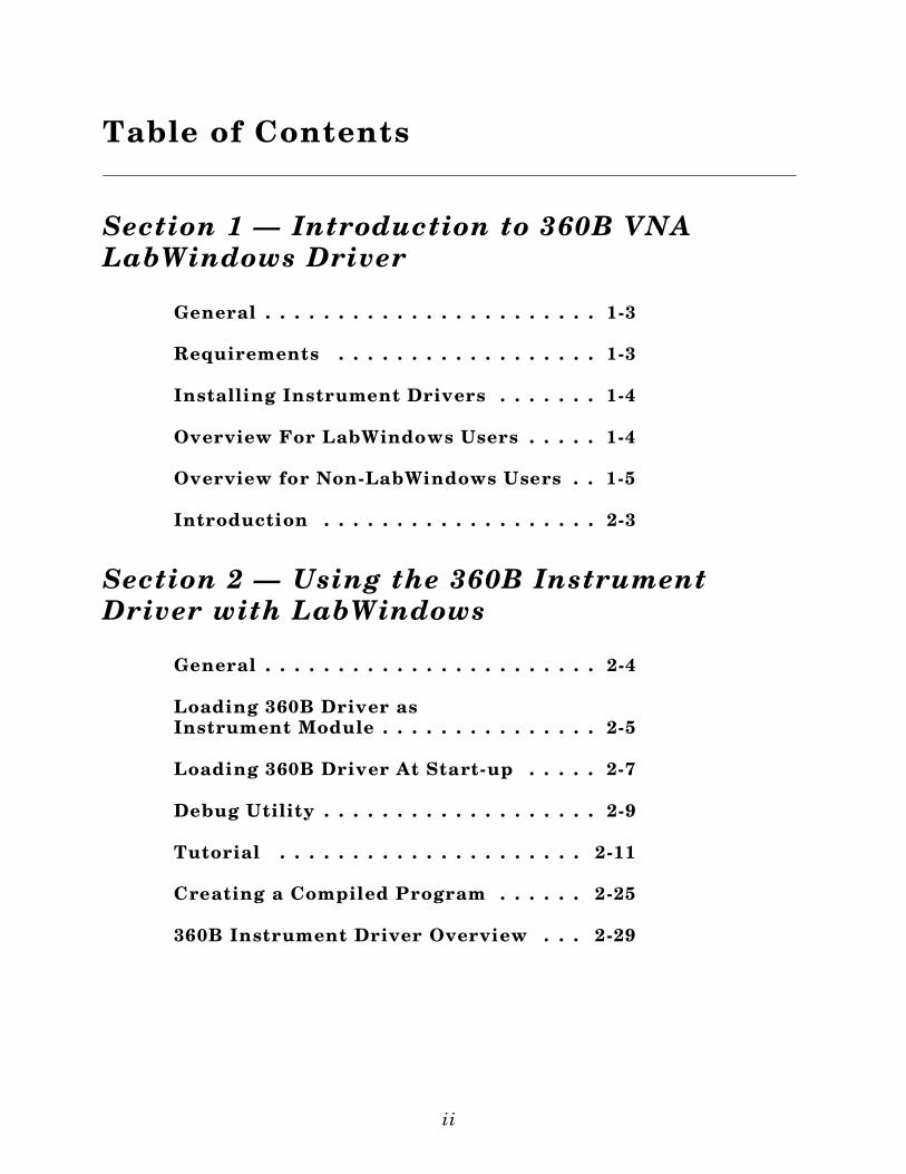
Table of Contents
Section 1 — Introduction to 360B VNA LabWindows Driver
General . . . . . . . . . . . . . . . . . . . . . . . 1-3
Requirements . . . . . . . . . . . . . . . . . . 1-3
Installing Instrument Drivers . . . . . . . 1-4
Overview For LabWindows Users . . . . . 1-4
Overview for Non-LabWindows Users . . 1-5
Introduction . . . . . . . . . . . . . . . . . . . 2-3
Section 2 — Using the 360B InstrumentDriver with LabWindows
General . . . . . . . . . . . . . . . . . . . . . . . 2-4
Loading 360B Driver as Instrument Module . . . . . . . . . . . . . . . 2-5
Loading 360B Driver At Start-up . . . . . 2-7
Debug Utility . . . . . . . . . . . . . . . . . . . 2-9
Tutorial . . . . . . . . . . . . . . . . . . . . . 2-11
Creating a Compiled Program . . . . . . 2-25
360B Instrument Driver Overview . . . 2-29
ii
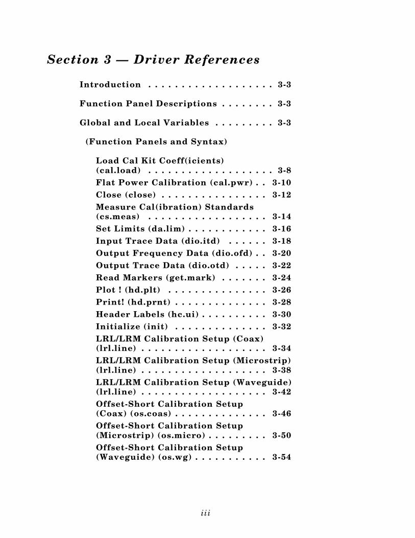
Section 3 — Driver References
Introduction . . . . . . . . . . . . . . . . . . . 3-3
Function Panel Descriptions . . . . . . . . 3-3
Global and Local Variables . . . . . . . . . 3-3
(Function Panels and Syntax)
Load Cal Kit Coeff(icients) (cal.load) . . . . . . . . . . . . . . . . . . . 3-8Flat Power Calibration (cal.pwr) . . 3-10Close (close) . . . . . . . . . . . . . . . . 3-12Measure Cal(ibration) Standards (cs.meas) . . . . . . . . . . . . . . . . . . 3-14Set Limits (da.lim) . . . . . . . . . . . . 3-16Input Trace Data (dio.itd) . . . . . . 3-18Output Frequency Data (dio.ofd) . . 3-20Output Trace Data (dio.otd) . . . . . 3-22Read Markers (get.mark) . . . . . . . 3-24Plot ! (hd.plt) . . . . . . . . . . . . . . . 3-26Print! (hd.prnt) . . . . . . . . . . . . . . 3-28Header Labels (hc.ui) . . . . . . . . . . 3-30Initialize (init) . . . . . . . . . . . . . . 3-32LRL/LRM Calibration Setup (Coax)(lrl.line) . . . . . . . . . . . . . . . . . . . 3-34LRL/LRM Calibration Setup (Microstrip)(lrl.line) . . . . . . . . . . . . . . . . . . . 3-38LRL/LRM Calibration Setup (Waveguide)(lrl.line) . . . . . . . . . . . . . . . . . . . 3-42Offset-Short Calibration Setup (Coax) (os.coas) . . . . . . . . . . . . . . 3-46Offset-Short Calibration Setup (Microstrip) (os.micro) . . . . . . . . . 3-50Offset-Short Calibration Setup (Waveguide) (os.wg) . . . . . . . . . . . 3-54
iii
Open-Short-Load Calibration Setup (Coax) (osl.coax) . . . . . . . . . . . . . 3-56Open-Short-Load Calibration Setup (Microstrip) (osl.micro) . . . . . . . . 3-60Recall Functions (recall.d) . . . . . . 3-64Save Functions (save.d) . . . . . . . . 3-66Averaging Factor (set.av) . . . . . . . 3-68Channel Definition (set.chdef) . . . 3-70Set Markers (set.mark) . . . . . . . . . 3-74Cartesian Scale (set.scc) . . . . . . . . 3-76Polar/Smith Scale (set.scp) . . . . . . 3-78Smoothing (set.smooth) . . . . . . . . 3-80Search Min/Max (set.srch) . . . . . . 3-82Domain Selection (set.td) . . . . . . . 3-84Set Gate (set.tdg) . . . . . . . . . . . . . 3-86Start/Stop Time (set.tdt) . . . . . . . . 3-88Video I.F. Bandwidth (set.vbw) . . . 3-90Channel Display Mode (set.vnad) . 3-92Blank Frequencies (su.blank) . . . . 3-94CW Sweep (setup.cw) . . . . . . . . . . 3-96Hold Functions (setup.hf) . . . . . . . 3-98N-Discrete Sweep (setup.ndis) . . . 3-100Power Levels (setup.sp) . . . . . . . . 3-102Step Sweep (setup.step) . . . . . . . . 3-104Time Domain Sweep (setup.tds) . . 3-106Trigger Selections (setup.trig) . . . 3-108Start Calibration (start.cal) . . . . . 3-110Math Functions (tdf.math) . . . . . . 3-112User Defined Coax (udef.coax) . . . 3-114User Defined Microstrip (udef.mic) . . . . . . . . . . . . . . . . . . 3-116User Defined Waveguide(udef.wg) . . . . . . . . . . . . . . . . . . 3-118Disk Utilities (ut.disc) . . . . . . . . . 3-120Video Configuration (ut.video) . . . 3-122
iv
Section 1
Introduction to the360B Vector
Network Analyzer (VNA)Driver
for LabWindows

Section 1Introduction to the 360B Vector Network Analyzer (VNA) Driver for LabWindows
General
WILTRON Instrument Drivers software provides an easy-to-use tool for developing application pro-grams for applicable microwave systems via the General Purpose Interface Bus (IEEE-488 Bus).
This software contains modules that automatically configure an applicable WILTRON instrumentfor use on the bus, along with high-level instrument control commands that save you the time re-quired to learn and program the GPIB commands of the instrument. The software automaticallychecks for proper bus functioning. If a command is sent to a bus instrument and no error is reported,the bus can be assumed to be working correctly.
Requirements
The WILTRON Instrument Driver software is written specifically for the model 360B VNA. How-ever, it may also be used with earlier Model 360 VNAs with the exception of a small number of func-tions.
The WILTRON Instrument Driver requires an IBM PC AT, PS/2, or compatible computer runningMS- or PC-DOS, Version 3.0 or later.
The software is delivered on 5-1/4 inch 1.2 Mb Floppy disks and 3-1/2 inch 1.4 Mb floppy disks.
At least 2 MB of memory is required to run the LabWindows program — 4 Mb is recommended.
The WILTRON Instrument Driver software requires National Instruments LabWindows version 2.2or later.
For Microsoft QuickBASIC, Professional BASIC, Visual BASIC for DOS, C, Quick C, and BorlandC++ and Turbo C++ users, you can use the 360B Instrument Driver software to produce compatibleinstrument-control-program code.
1-3

Installing Instrument Drivers
This section provides instructions for installing the WILTRON Instrument Drivers. Proceed asfollows:
Insert the WILTRON driver diskette in your A: or B: drive, as appropriate.
Change to the LabWindows, Instruments directory (drive\LW\INSTR), and type the followingDOS command: COPY A: (B:) *.*. This copies the following eight files to the target subdirec-tory: W360B.LBW, W360B.LWI, W360B.FP, W360B.DOC, W360BCAL.LBW,W360BCAL.LWI, W360BCAL.FP, W360BCAL.DOC (All of these files MUST reside within thesame subdirectory.)
Once the copying is completed, return the driver diskette to a safe storage location.
Overview For LabWindows Users
LabWindows is a software development system for BASIC, C, and C++ programs (see page 1-3 forlisting of supported languages). It contains an interactive environment for developing programs withdrivers and libraries (functions) for creating data acquisition and instrument control applications.LabWindows contains a comprehensive set of software tools for data analysis, data presentation, andhigh level instrument control.
The interactive program is an environment for editing and debugging BASIC and C (C++) programs.In the LabWindows environment, you can use the functions in the instrument drivers or libraries towrite your program. In addition each function has an interface called a function panel that lets youinteractively execute the function or generate code for calling the function.
The interactive program uses extended memory. Programs executed in the interactive program canuse up to 16 megabytes of memory, depending on your computer configuration. Programs that run inthe interactive program, however, must adhere to the LabWindows subsets for BASIC, C and C++.
Programs developed with the drivers and library functions can be run within the interactive pro-gram, or they can be compiled and linked into a stand-alone applicaton (*.EXE) or run-time applica-tion (*.RTM) file. To help you create a stand-alone program, LabWindows incorporates utilities thatautomate the compile and link processes.
The real power of LabWindows lies in the libraries. They have functions for developing all phases ofyour data acquisition and instrument control system. For controlling the 360B , Lab Windows hasthe Instrument Drivers Library. Programs that call this library can be developed with the interac-tive program. This program has tools that make program development quicker and easier.
LabWindows gives you the capability to execute instrument drivers with the aid of panels andthereby create programs easily. The panels contain items that can be selected to build and execute adriver. The drivers are separately declared in the Instrument Drivers Library.
360B LabWindows Driver User’s Guide
1-4
Two advantages of using LabWindows are:
When writing an application program you do not have to remember all of the parameters thatbelong to the driver.
Error reporting is shown automatically in the panels.
Overview for Non-LabWindows Users
Programmers who do not use LabWindows will also benefit from the WILTRON Instrument Driversoftware:
You will not have to know all of the GPIB codes needed to program applications for the 360BVNA. The driver software effectively manages low-level GPIB I/O operations and native instru-ment control.
You will see greater program reliability because of the driver’s extensive error-checking rou-tines.
You will see reductions in the time required to develop, test, and debug applications.
1-5/1-6
Section 1

Section 2
Using the 360B Instrument Driver with LabWindows
Section 2Using the 360B Instrument Driver with LabWindows
Introduction
This section provides an introduction to the LabWindows environment and a tutorial de-scribing the use of the 360B driver within LabWindows. This section assumes that youhave read Part 1 of the National Instruments Getting Started with LabWindows manu-als and are generally familiar with the LabWindows screen and principles of naviga-tion within the environment.
The 360B driver consists of two separate instrument modules. The first, W360B.FP,contains all of the general setup, display, analysis, and I/O functions. The second,W360BCAL.FP, contains all of the vector error correction, or calibration, setup andmeasurement functions.
2-3

General
The following procedure describes how to access LabWindows and load files.
Mo ve t o th e d i re c to ry co nta in ing the L abWind o ws ex ec utab le ( * .EX E)f i l es . (T hi s d i re c to ry i s usu a l l y n amed \L W. )
T yp e L W . T hi s p lace s yo u in th e P ROGRAM wind o w of the L abWind o ws e nv i ro nme nt (be l o w) .
360B LabWindows Driver User’s Guide
2-4
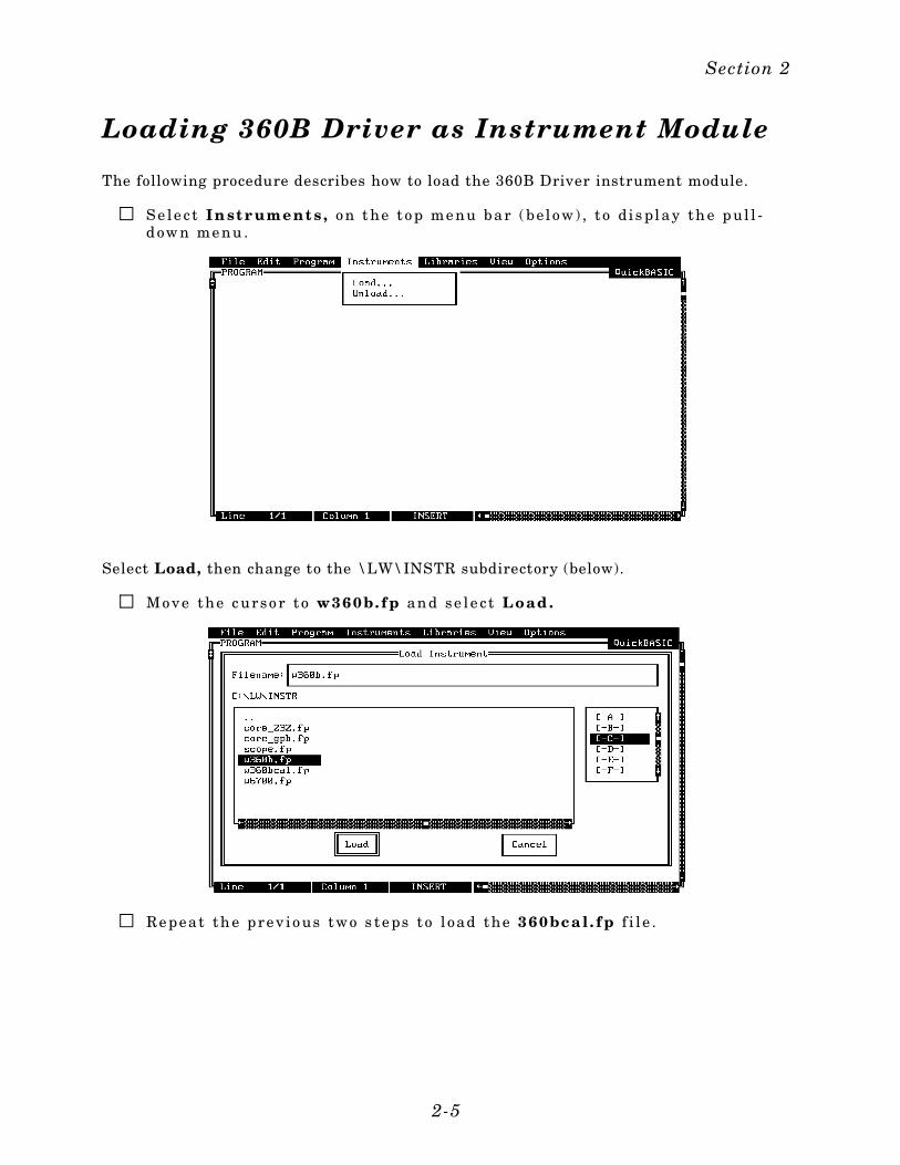
Loading 360B Driver as Instrument Module
The following procedure describes how to load the 360B Driver instrument module.
Se le c t In st r ument s , o n t he t o p me nu bar ( bel o w) , t o di s play th e p ul l -d ow n me nu .
Select Load, then change to the \LW\INSTR subdirectory (below).
Mo ve the c urso r t o w360b. fp an d se l e c t Load .
Re peat th e pre v io us two s te ps t o l oad the 360bca l . fp f i l e .
Section 2
2-5
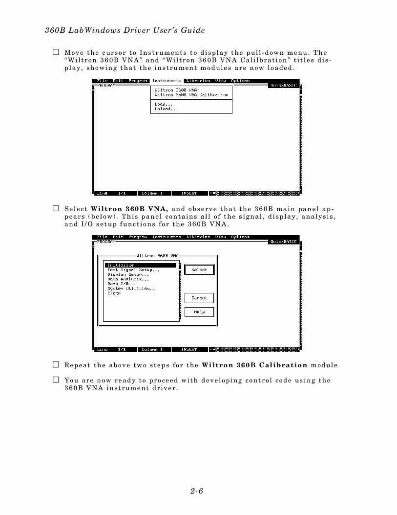
Mo ve the c urso r t o I ns t rume nt s t o d i sp lay t he p ul l - d ow n me nu . Th e“Wi l t ro n 360B VNA” and “Wi l t ro n 360B VNA Ca l i l b ra t i o n” t i t l e s d i s -p lay , sho win g t hat the in st ru men t mo d ule s are no w l o ade d .
Se le c t Wilt r on 360B VNA, an d o bse rve t hat the 360B main pan el ap -p ear s ( be l o w) . Th is p ane l co nta ins a l l o f the s i gna l , d i sp lay , ana ly s i s ,and I / O s et up f unc t i o ns fo r the 360B VNA.
Re peat th e abo ve tw o s te p s fo r the Wi lt ro n 360B Cal ibrat io n module .
Yo u are n ow re ad y t o p ro ce e d wi th d e ve l op ing co nt ro l co d e us ing the360B VNA ins t rume nt d r ive r .
360B LabWindows Driver User’s Guide
2-6
Loading 360B Driver At Start-up
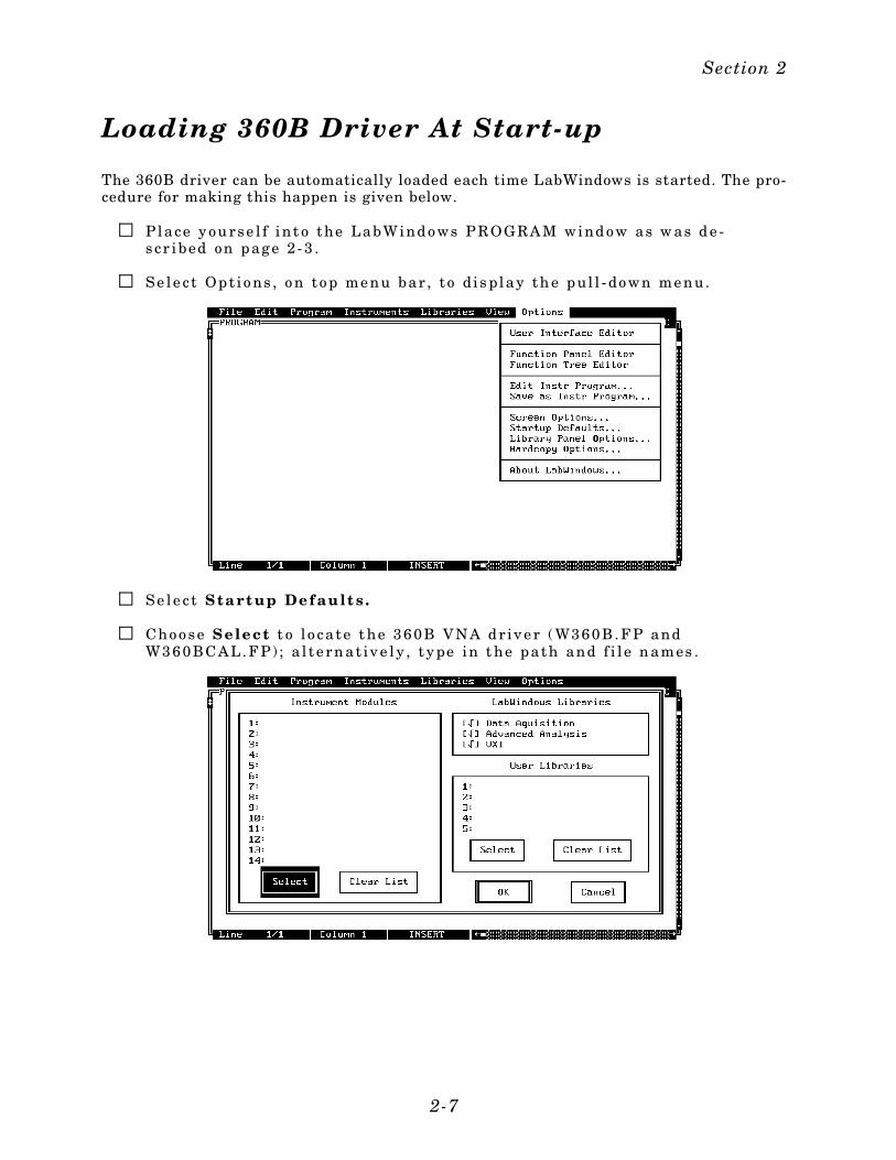
The 360B driver can be automatically loaded each time LabWindows is started. The pro-cedure for making this happen is given below.
P lace y ou rse l f int o the LabWind o ws P ROGRAM wind o w as w as d e -s cr ibed on p age 2 - 3 .
Se l e c t Op t i o ns , o n t o p me nu bar , t o di s play th e p ul l - do wn me nu.
Se le c t S ta rt up Defau lt s .
Cho o se Select t o l o ca te t he 360B VNA d r ive r ( W360B. F P andW360BCAL. F P) ; a l t e rn at ive ly , t y pe in t he path and f i l e n ames .
Section 2
2-7
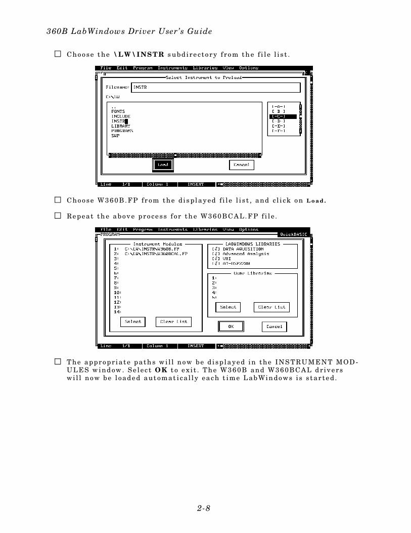
Cho o se t he \LW\I NSTR s ubd i re c to ry f ro m th e f i l e l i s t .
Cho o se W360B. FP fr om the di s play ed f i l e l i s t , and c l i ck o n L o a d .
Re peat th e abo ve pro ce ss f or th e W360BCAL. F P f i l e .
T he appro p r ia te pa th s w i l l no w be d i sp laye d in the INS TRUM ENT MOD -UL ES w ind ow . Se l ec t OK t o e x i t . T he W360B and W360BCAL d r ive rswi l l no w be l oade d aut omat i ca l l y eac h t ime L abWin do ws i s s tar te d.
360B LabWindows Driver User’s Guide
2-8
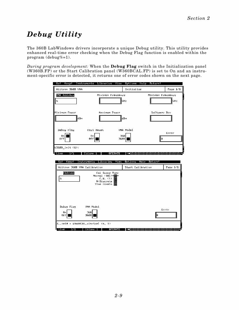
Debug Utility
The 360B LabWindows drivers incorporate a unique Debug utility. This utility providesenhanced real-time error checking when the Debug Flag function is enabled within theprogram (debug%=1).
During program development: When the Debug Flag switch in the Initialization panel(W360B.FP) or the Start Calibration panel (W360BCAL.FP) is set to On and an instru-ment-specific error is detected, it returns one of error codes shown on the next page.
Section 2
2-9

300 - No GP I B Re sp o nse
301 - P arame te r Ran ge Err or
302 - No Va l id M emo ry T race
303 - I nva l id f i l e n ame
305 - Une xp e cte d SRQ
306 - No va l id use r de f ine d p arame te rs
310 - I nte rna l d i sk d r ive e rr or
311 - Se l f T e s t Fa i l e d
312 - Har dw are e rro r
314 - Act i o n no t po ss ib l e
When the Debug Flag utility is off (DEBUG=0), no instrument-specific error messagesare returned (except for 305).
When the function is set to on, execution of the program is slowed. Its use adds 300 msto the execution of each command string. Consequently, we recommend that it be en-abled only during program development, and that it be disabled before the program iscompiled.
360B LabWindows Driver User’s Guide
2-10
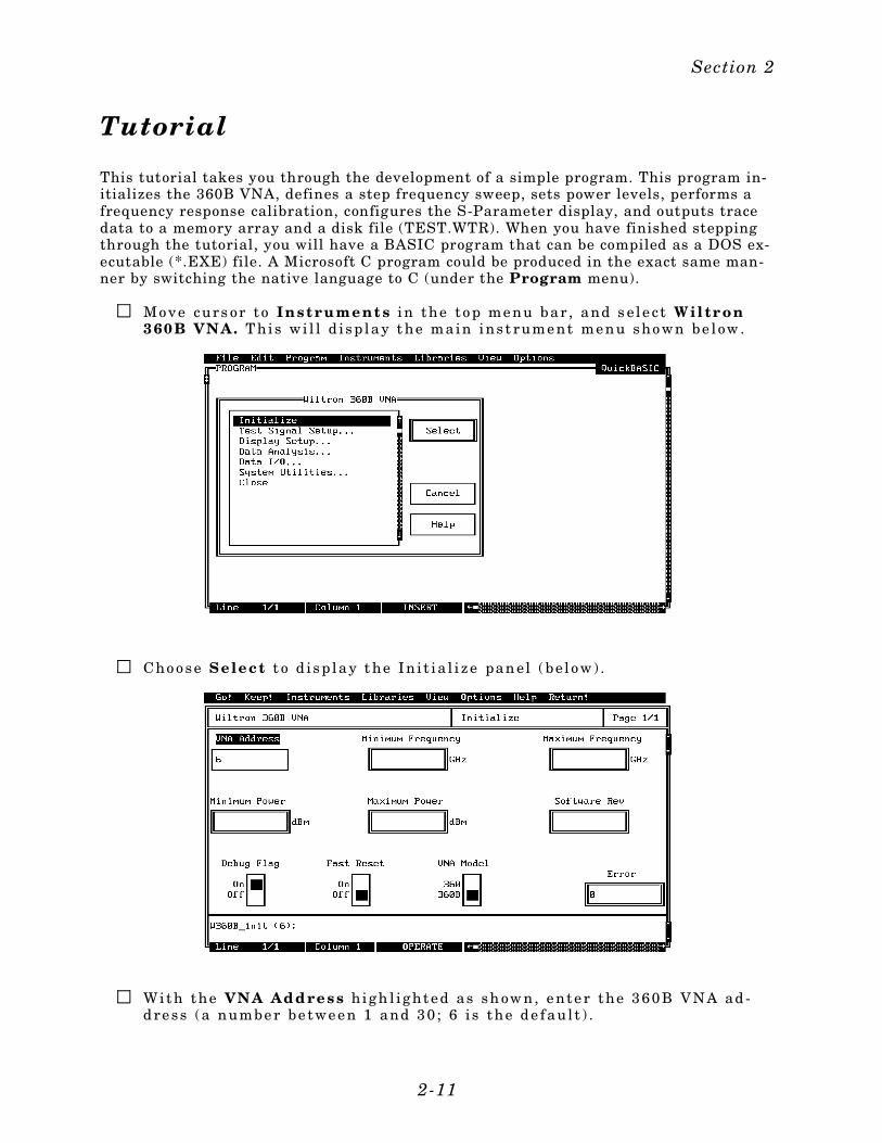
Tutorial
This tutorial takes you through the development of a simple program. This program in-itializes the 360B VNA, defines a step frequency sweep, sets power levels, performs afrequency response calibration, configures the S-Parameter display, and outputs tracedata to a memory array and a disk file (TEST.WTR). When you have finished steppingthrough the tutorial, you will have a BASIC program that can be compiled as a DOS ex-ecutable (*.EXE) file. A Microsoft C program could be produced in the exact same man-ner by switching the native language to C (under the Program menu).
Mo ve curs or t o Inst ru ment s i n the t o p me nu bar , and s e l e c t Wil tr on360B VNA. T his wi l l d i sp lay t he main ins t rume nt me nu sho wn be low .
Cho o se Select t o d i sp lay t he In i t i a l i ze pan el ( be l o w) .
Wi th the VNA Address high l ighte d as sh ow n, e nte r the 360B VNA ad -d re ss (a numbe r be twe e n 1 and 30 ; 6 i s the d e f aul t ) .
Section 2
2-11

Se le c t Go ! ( be l o w) in the t o p me nu bar . I f a 360B i s co nne cte d an d se tto G PIB addre ss 6 , i t wi l l re spon d by re se t t ing i t s e l f and re tu rning aniden t i f i ca t i o n s t r in g t hat wi l l f i l l the Min imu m Fr equ en cy, Maxi mumFrequen cy, Mini umu m P ower, Maxi mum Power , and F ir mwar e Revf i e ld s .
L e ave th e Debug Fl ag and Fast Reset swi t ch se t t o Of f . Th e De bugF lag s wi t ch i s d i scus se d o n p age 2 -8 , F ast Re se t i s d i sc usse d o n p age 3 -32 .
Mo ve the c urso r t o Keep ! , i n the t op men u bar , the n cho o se Keep f ro mthe ne xt wind o w ( be l o w) t o se l ec t t he d e fau l t o p t i o n . T hi s t ran s f er s t heco d e sho wn at the bot to m o f th e p ane l t o the P ROG RAM w ind ow o f th eL abWin do ws e nv i r on men t .
Se le c t In st r ument s , in the t op men u bar , the n 360B VNA t o re tu rn tothe 360B Dr ive r main p ane l .
360B LabWindows Driver User’s Guide
2-12
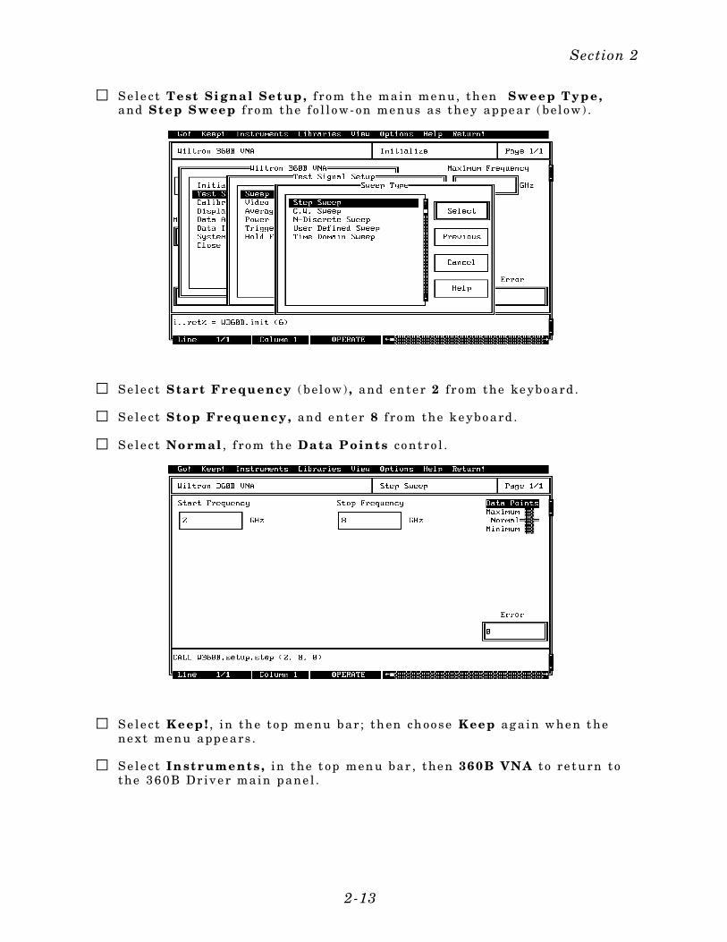
Se le c t Test Si gna l Set up , f ro m t he main me nu, th en Sweep Type ,and S tep Sweep f ro m the f o l l o w- on me nus as the y ap pe ar ( bel o w) .
Se le c t Sta rt Fr equency ( be l o w) , and en te r 2 f r om the ke ybo ard .
Se le c t S to p Frequency, and e nt er 8 f ro m the k e ybo ard .
Se le c t No rmal , f ro m th e Da ta P oin ts co nt ro l .
Se le c t Keep ! , in th e t o p me nu bar ; th en ch oo se Keep ag a in w he n t hene xt me nu app e ars .
Se le c t In st r ument s , in the t op men u bar , the n 360B VNA t o re tu rn tothe 360B Dr ive r main p ane l .
Section 2
2-13
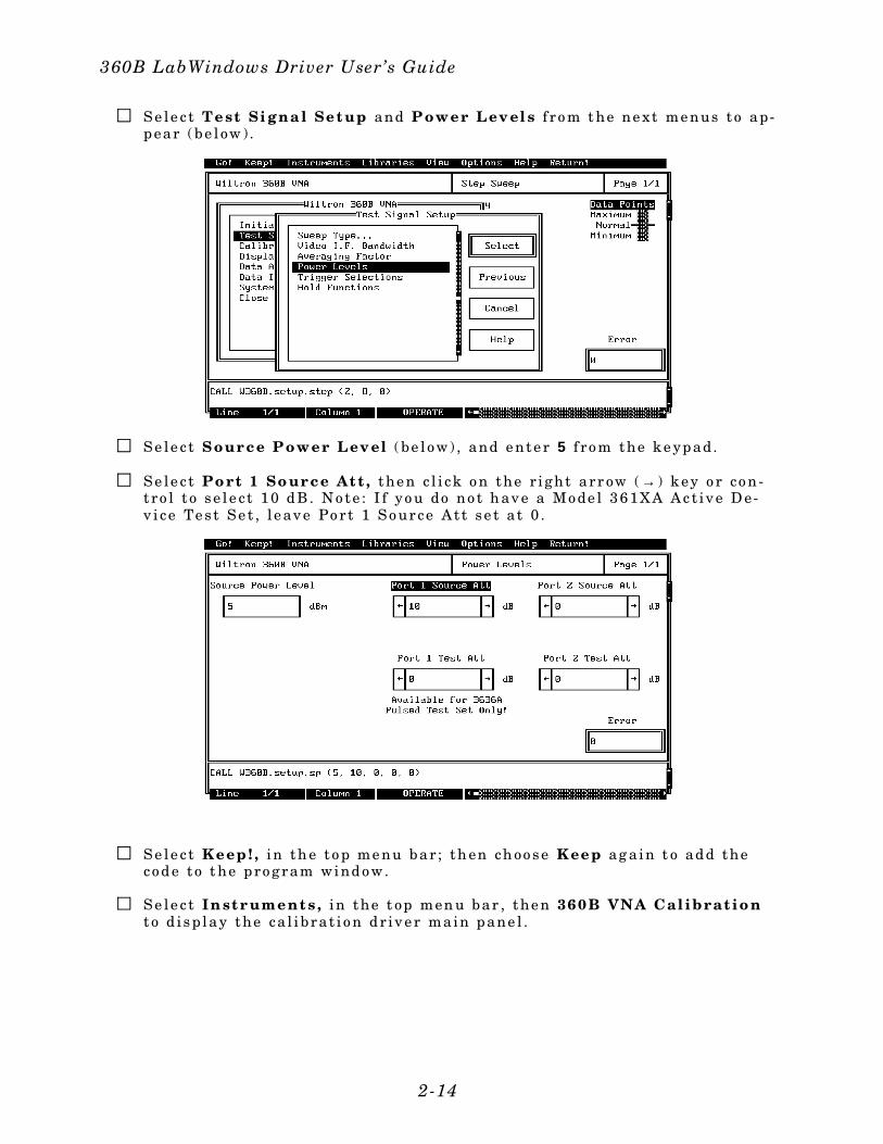
Se le c t Test Si gna l Set up and P ower Lev el s f ro m t he ne xt me nus t o ap-p ear ( be l ow ) .
Se le c t Sour ce P ower Lev el ( be l o w) , and e nte r 5 f ro m the k e yp ad.
Se le c t Po rt 1 So ur ce At t , the n c l i ck o n the r i ght arr ow ( → ) k ey o r co n-t ro l t o se l e c t 10 d B . No te : I f yo u do no t h ave a Mo de l 361XA Ac t ive D e-v i ce Te st Se t , l e ave Po r t 1 So urce At t se t a t 0 .
Se le c t Keep ! , in th e t o p me nu bar ; th en ch oo se Keep ag a in t o ad d theco d e t o t he p ro gram wind o w.
Se le c t In st r ument s , in the t op men u bar , the n 360B VNA Cal ibrat io nt o d i sp lay the ca l ib ra t i o n dr ive r main pane l .
360B LabWindows Driver User’s Guide
2-14
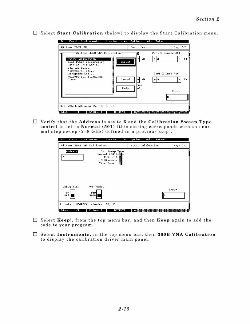
Se le c t Sta rt C ali br at ion ( be l o w) t o di s play th e S tar t Ca l ibr at i o n me nu .
Ve r i f y that the Address i s se t t o 6 and the C ali br at ion Sweep Typeco ntr o l i s se t t o No rmal ( 501) ( t h i s se t t ing co rr es po nd s wi th th e no r -mal s te p swe e p ( 2–8 G Hz) d e f ine d in a p re v io us s te p ) .
Se le c t Keep ! , f ro m the t op men u bar , and th en Keep aga in to ad d t heco d e t o y ou r p ro gr am.
Se le c t In st r ument s , in the t op men u bar , the n 360B VNA Cal ibrat io nt o d i sp lay the ca l ib ra t i o n dr ive r main pane l .
Section 2
2-15
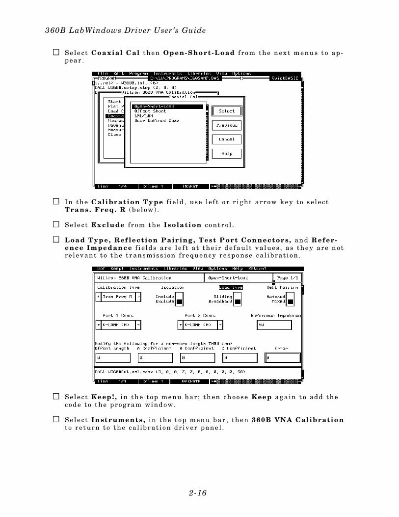
Se le c t Coa xial C al the n Open-Sho rt -Load f ro m the n ex t me nu s t o ap -p ear .
I n the C ali br at ion Ty pe f i e ld , use l e f t o r r i ght arro w ke y t o s e l e c tTra ns . Freq . R ( be l o w) .
Se le c t Ex clu de f r om the Isola ti on co nt r o l .
Loa d Type , Ref lect ion P air ing , Test P or t Con nect or s, an d Refer-ence I mpedan ce f i e ld s are l e f t a t t he i r d e f aul t va lue s , as the y are n otre l e vant t o t he t r ansmiss i on f re que ncy re sp o nse ca l ibra t i o n .
Se le c t Keep ! , in th e t o p me nu bar ; th en ch oo se Keep ag a in t o ad d theco d e t o t he p ro gram wind o w.
Se le c t In st r ument s , in the t op men u bar , the n 360B VNA Cal ibrat io nt o r et urn to t he ca l ibr a t i o n d r iv er p ane l .
360B LabWindows Driver User’s Guide
2-16

Se le c t Mea sure St an dards f ro m the main ca l ibr a t i o n d r iv er p ane l ( be -l o w) .
Se le c t Begin C al o n t he Nex t Cal Step s l i d e sw i t ch ( bel o w) .
Se le c t Keep ! , in th e t o p me nu bar ; th en ch oo se Keep ag a in t o ad d theco d e t o t he p ro gram wind o w.
Se le c t In st r ument s , in the t op men u bar , the n 360B VNA Cal ibrat io nt o r et urn to t he ca l ibr a t i o n d r iv er p ane l .
Section 2
2-17
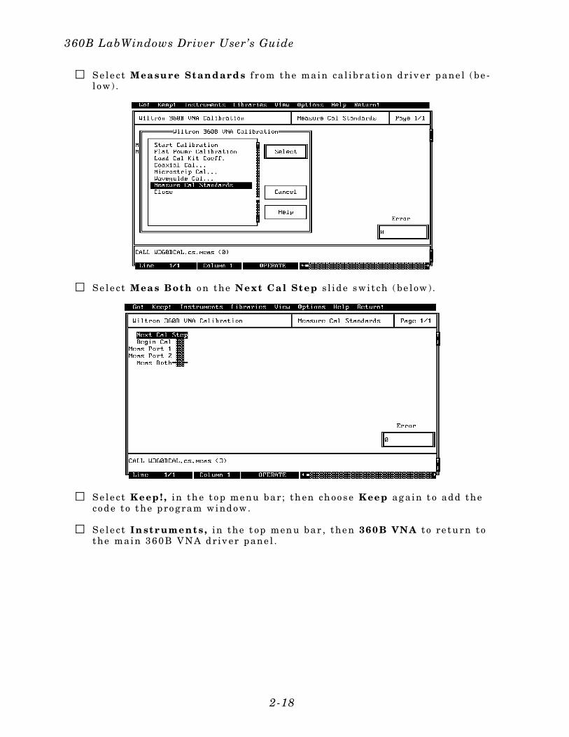
Se le c t Mea su re St an dards f ro m the main ca l ibr a t i o n d r iv er p ane l ( be -l o w) .
Se le c t Mea s Bot h o n the Next Ca l St ep s l i d e s wi t ch ( be l ow ) .
Se le c t Keep ! , in th e t o p me nu bar ; th en ch oo se Keep ag a in t o ad d theco d e t o t he p ro gram wind o w.
Se le c t In st r ument s , in the t op men u bar , the n 360B VNA t o re tu rn tothe main 360B VNA d r iv er p ane l .
360B LabWindows Driver User’s Guide
2-18
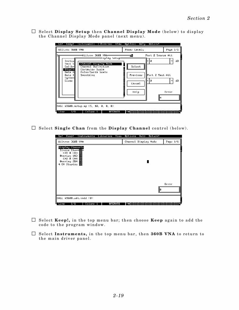
Se le c t Di spl ay Set up the n Cha nn el D is p lay M od e ( be l ow ) t o d i sp laythe Channe l Di sp lay Mo de pan el ( ne xt men u) .
Se le c t Sing le C han f ro m the D isp lay Ch an nel co nt r o l ( be l o w) .
Se le c t Keep ! , in th e t o p me nu bar ; th en ch oo se Keep ag a in t o ad d theco d e t o t he p ro gram wind o w.
Se le c t In st r ument s , in the t op men u bar , the n 360B VNA t o re tu rn tothe main dr iv er pane l .
Section 2
2-19

Se le c t Di spl ay Set up the n Cha nn el D ef in it ion ( be l ow ) t o d i sp lay theChann el De f in i t i o n pan el ( ne xt men u) .
Se le c t CH1 and S21 f ro m th e ap pr op r ia t e co ntr o l s o n the me nu sh ow nbe low , the n c l i ck tw i ce o n the r i ght arro w ( → ) ke y o r c on tro l t o se l e c tSmit h Cha rt .
Se le c t Keep ! , in th e t o p me nu bar ; th en ch oo se Keep ag a in t o ad d theco d e t o t he p ro gram wind o w.
Se le c t In st r ument s , in the t op men u bar , the n 360B VNA t o re tu rn tothe main dr iv er pane l .
360B LabWindows Driver User’s Guide
2-20
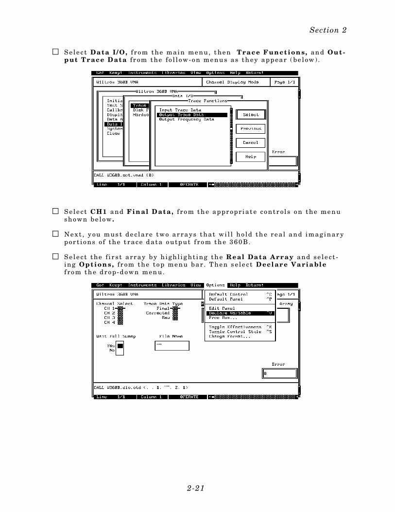
Se le c t Da ta I / O, f ro m the main me nu, t he n Tra ce Fun ct ion s, an d Ou t -put Tr ace Data f r om the fo l l o w- o n me nu s as th ey ap p ear ( be l ow ) .
Se le c t CH1 and F in al D at a , f ro m th e ap pr op r ia t e co ntr o l s o n the me nusho wn be lo w .
Ne xt , y ou mus t de c lare two ar rays that wi l l ho ld th e re a l an d imaginar yp or t i o ns o f the t race d ata o utp ut f ro m th e 360B.
Se le c t the f i r s t array by h ighl i g ht ing th e Real Da ta A rr ay and se le c t -ing Opt ion s , f r om the t o p me nu bar . T he n s e l e c t D ecl ar e Va ria bl ef ro m th e d ro p- d o wn men u.
Section 2
2-21
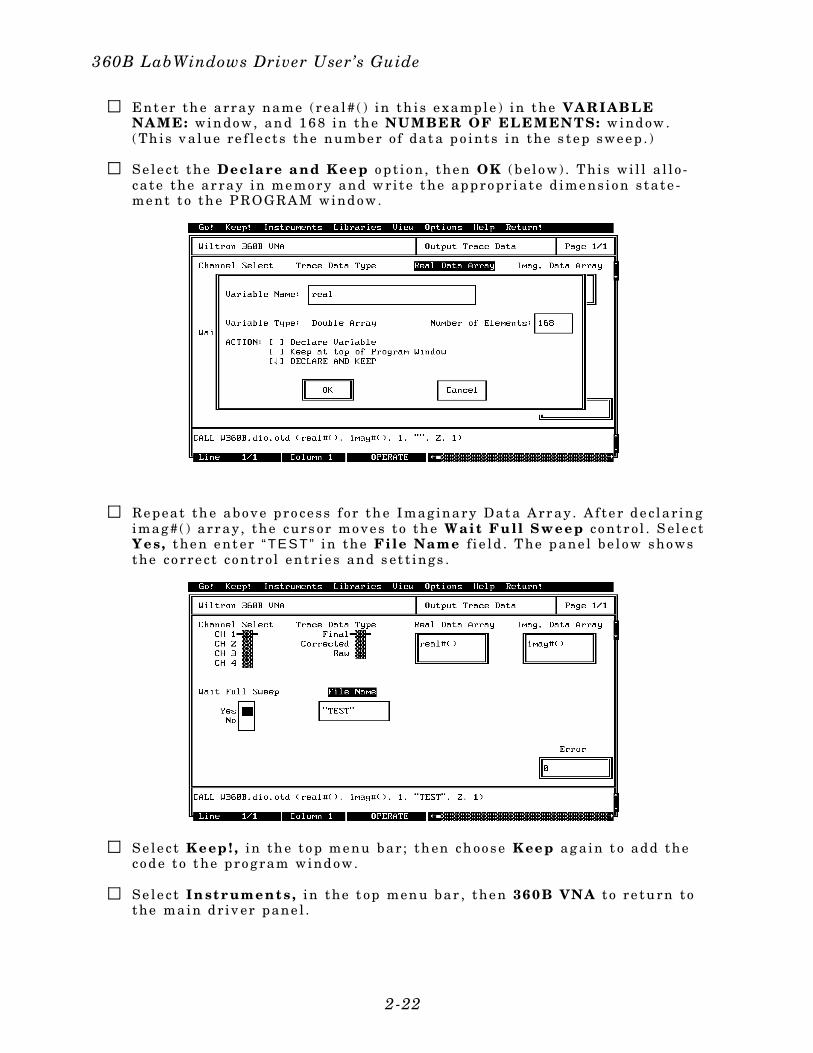
Ent er th e array name (r ea l# ( ) in th i s e xample ) in the VA RIAB LENA ME: w in do w, an d 168 in th e NUMBER OF ELE MENTS: w ind ow .( Th i s v a lue re f l e c t s the numbe r o f dat a p o ints in the s te p swe e p . )
Se le c t the Decla re a nd Keep o p t i o n , the n OK ( be l o w) . T hi s wi l l a l l o -ca te the ar ray in me mo ry and w r i te t he ap p ro pr ia te d ime ns io n s ta te -me nt t o th e P ROGRAM wind o w.
Re peat th e abo ve pro ce ss f or th e I mag inary Dat a Arr ay . A f te r de c lar in gimag#( ) a rr ay , the curs or mo ve s t o th e Wait Fu ll Sweep co ntr o l . S el e c tYes, t he n e nt er “ TE S T” in the File Name f i e ld . T he p ane l be l o w sho wsthe co rre c t co ntr o l e nt r i e s and s et t ings .
Se le c t Keep ! , in th e t o p me nu bar ; th en ch oo se Keep ag a in t o ad d theco d e t o t he p ro gram wind o w.
Se le c t In st r ument s , in the t op men u bar , the n 360B VNA t o re tu rn tothe main dr iv er pane l .
360B LabWindows Driver User’s Guide
2-22
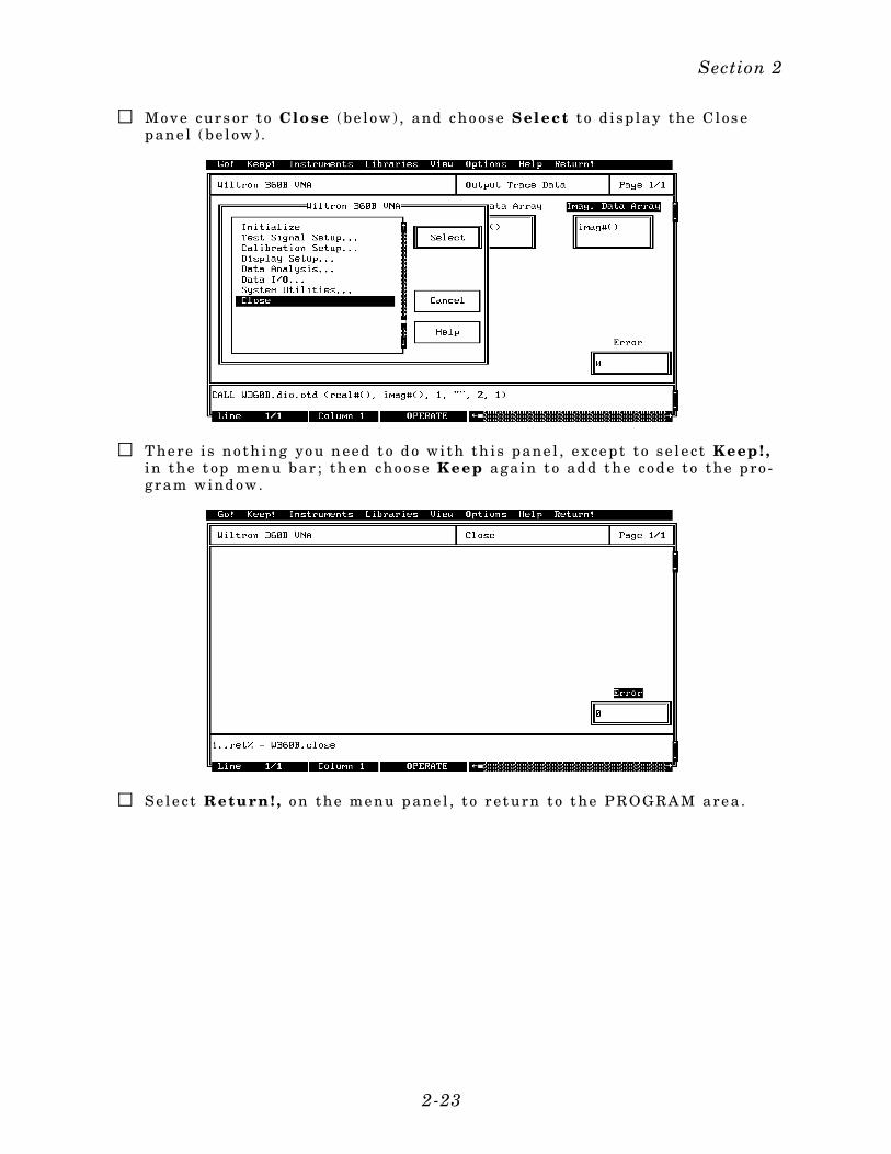
Mo ve curs or t o Clo se (be l o w) , and c ho os e S el e ct t o d i sp lay the C los ep ane l ( be l ow ) .
T he re i s no th ing yo u n ee d t o d o wi th th i s p ane l , e xce p t t o se l e c t Keep ! ,in the t op men u bar ; the n cho o se Keep aga in t o ad d t he co d e t o t he p ro -gram wind o w.
Se le c t Retu rn ! , o n the me nu p ane l , t o r et urn to t he P ROGRAM are a .
Section 2
2-23
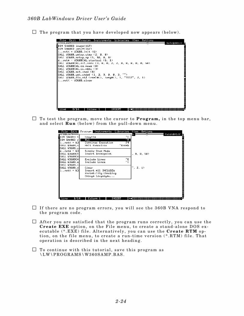
T he p ro gr am th at y ou hav e d ev el o p e d no w app e ars ( be l o w) .
T o t e s t th e pro gram, mo ve t he cu rso r t o P rog ram, in th e t o p me nu bar ,and s e l e c t Ru n (be l o w) f ro m the p ul l - d o wn men u.
I f th er e are n o pro gram er ro rs , yo u wi l l s e e the 360B VNA re spon d tothe pr og ram c ode .
A f te r yo u ar e sa t i s f i e d t hat the p ro gr am ru ns co rre c t l y , yo u c an u se th eCr ea te EXE o p t i o n , o n t he F i l e me nu, t o c re ate a s t and -a l o ne DOS e x -e cutab le (* . EXE) f i l e . A l te rnat iv ely , yo u c an u se th e Cr ea te RTM o p-t i o n , o n the f i l e me nu , t o c r eat e a r un- t ime v er s i o n ( * .RT M) f i l e . T hato pe rat i on i s des cr ibe d in the ne xt he adin g .
T o co nt inue w i th th i s tut or ia l , save t h i s pr og ram as \L W\P ROGRAMS \W360SAMP .BAS .
360B LabWindows Driver User’s Guide
2-24
Creating a Compiled Program
Most programs developed with LabWindows can be compiled with the Microsoft C orBASIC compiler. Some program modules, however, exceed the 64 KB BASIC memorylimit and must be run within LabWindows or the LabWindows Run-Time System. TheLabWindows Run-Time System includes a DOS extender so programs can access up to16 MB of memory during execution. Programs executed in the run-time system canmake calls to any of the LabWindows libraries and instrument drivers. Programs dis-tributed with the run-time system are in a binary format, so the programs cannot beedited. A stand-alone application (*.EXE or *.RTM) that incorporates the 360B Drivermay be created using the Microsoft C or BASIC compilers or LabWindows Run-TimeSystem.
To avoid OUT OF MEMORY errors when using the Microsoft BASIC compiler, you mustfirst optimize the 360B Drivers (W360B.BAS and W360BCAL.BAS) memory usage withthe LabWindows FUNNEL.EXE utility (See LabWindows User’s Manual for instruc-tions).
The LWMAKE option on the file menu can be used to create an executable file in eitherBASIC or C. The following provides a step-by-step tutorial for creating a *.EXE file us-ing the BASIC 7.1 compiler. This tutorial assumes that you have read and are familiarwith the LWMAKE utility description in the Lab Windows User’s Manual and with theMicrosoft BASIC compiler and linker. (It also assumes that you have already run theFUNNEL.EXE used to optimize the W360B.BAS and W360BCAL.BAS files.)
We will start with the program that you completed in the preceeding tutorial. If youdid not complete the tutorial, you can create the program listing shown on the preceed-ing page, and save it as d\LW\PROGRAMS\W360SAMP.BAS.
Mo ve the c urso r t o I nst ru men t s, i n th e t o p me nu bar , and en sure thatthe Wi lt ro n 360B VNA and W360B VNA Cal ibra ti on d r i ve rs arel o ade d . I f the y are n ot l o ad ed , re f e r t o p age s 2 - 4 and 2 - 5 f o r ins t r uc -t i o ns .
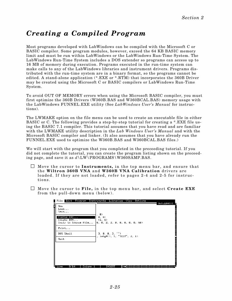
Mo ve the c urso r t o Fi le , in the t op men u bar , and se l e c t Cr ea te EXEf ro m th e p ul l - do wn me nu ( bel o w) .
Section 2
2-25
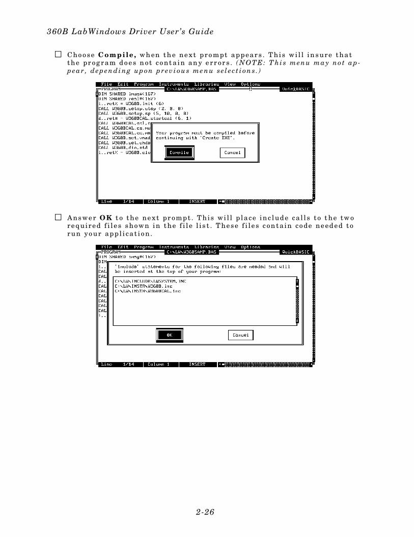
Cho o se C ompile , wh en th e ne xt pro mpt appear s . T hi s wi l l in sure thatthe pr og ram d o e s n ot co nt a in an y e rr or s . ( NOTE: T hi s menu ma y no t a p-p ea r , dep en di ng up on p rev i ou s me nu se l ec t i on s . )
Ans we r OK t o the ne xt pr ompt . T hi s wi l l p lace inc lud e ca l l s t o t he tw ore qui re d f i l e s sho wn in the f i l e l i s t . T he se f i l e s c on ta in co de ne ed e d torun yo ur ap p l i ca t i o n .
360B LabWindows Driver User’s Guide
2-26
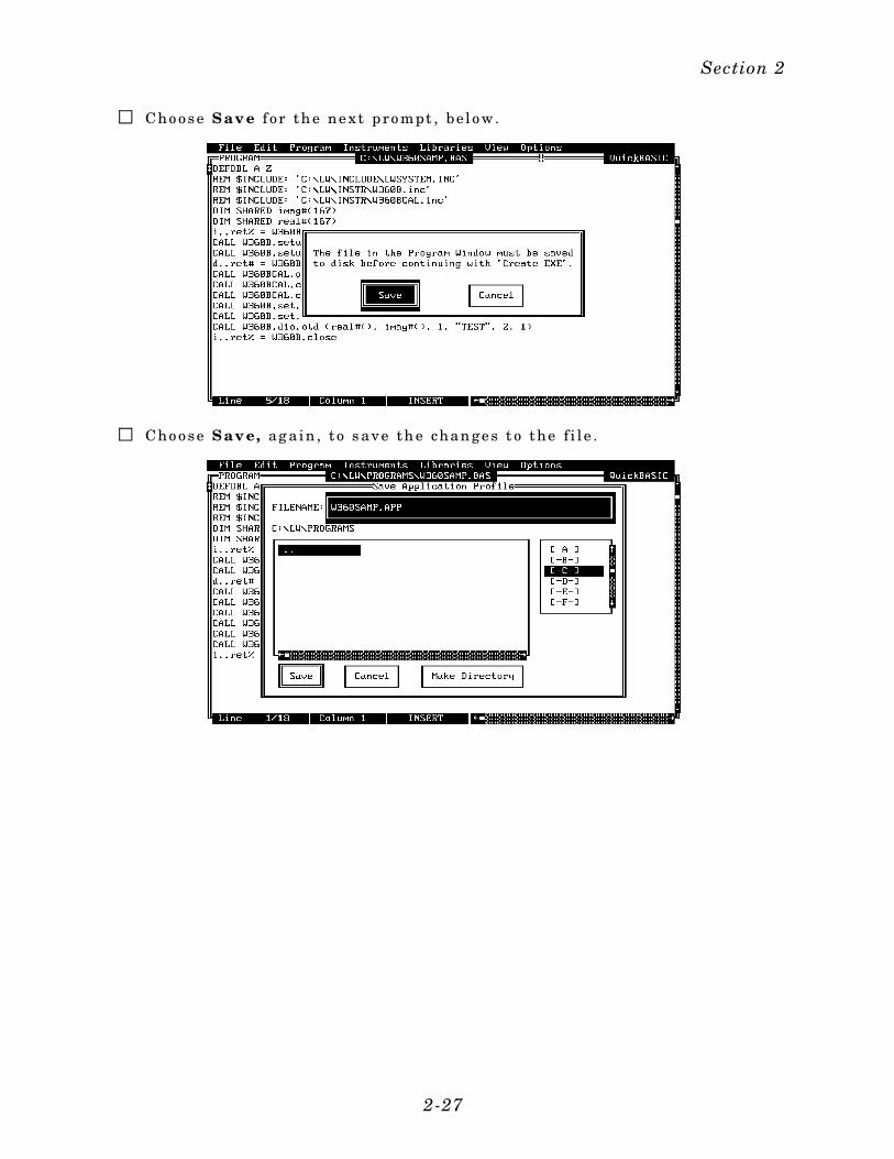
Cho o se Sav e f or th e ne xt p ro mpt , be l o w.
Cho o se Sav e, ag a in , t o s ave th e chan ge s t o the f i l e .
Section 2
2-27
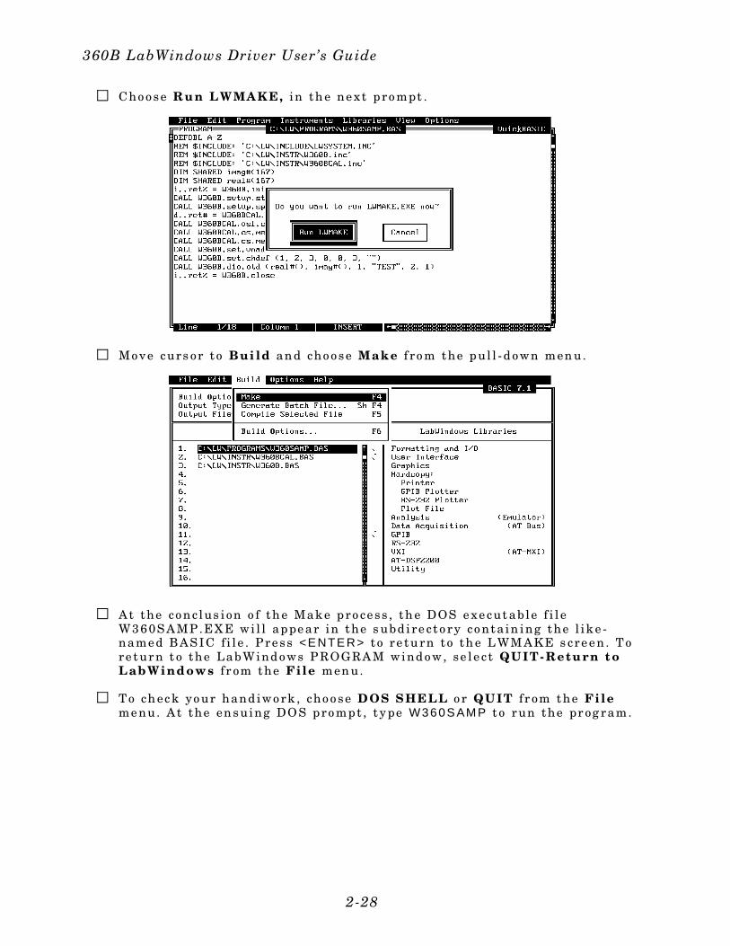
Cho o se Ru n LWMA KE, i n th e ne xt p ro mpt .
Mo ve curs or t o Bui ld an d cho o se Make f ro m the p ul l - d o wn men u.
At the co nc lus i on o f th e Mak e p ro ce ss , th e DOS e xe cut ab le f i l eW360SAMP .EX E wi l l appe ar in the s ubd i re c to ry co nta in ing the l ik e -name d BASI C f i l e . P re ss <E NTE R> t o re tu rn to th e L WM AKE s cre e n . T ore tur n t o the LabWind o ws P ROGRAM wind o w, se l e c t QUIT- Retu rn t oLabWindows f r om the File men u.
T o ch ec k yo ur hand iwo rk , cho o se D OS S HE LL o r QUIT f r om the Fileme nu. At the en suing DO S pro mpt , t y pe W360S AM P t o run the pr og ram.
360B LabWindows Driver User’s Guide
2-28
360B Instrument Driver Overview
This following pages provide an overview description of the 360B Instrument Driverthat includes listings and descriptions for the instrument panels.
General
For the 360B driver function panels, the following can be used as rules of thumb:
F re que ncy va lu es are in g igahe rtz ( GHz) uni t s .
T ime p arame te rs are in nan os ec on ds ( ns ) .
Di s tance and o f fs et - l e ng th par amet er s ar e in mi l l imet er s ( mm) .
A l l hard - co py o utput s w i l l co mme nce on e xe cut i on o f pane l ( GO ! ) o r l ineo f co d e .
A fu l l re se t i s re co mmen de d a t th e s tar t o f an y pro gr am to insur ep ro pe r co mmunic at i o n w i th the 360B sys te m. A f as t re se t can be use df or a l l subse que nt o p er at i o ns i f ne ce ssar y .
T he de bug capab i l i t i e s inc lud e d wi t h t he dr ive r sho uld be use d f o r pr o-gram dev elo pme nt on ly . T hi s adde d f unc t i o na l i ty sho uld be d i sab le dwhe n co mpi l ing s tand - a l o ne app l i ca t i o ns us in g t h i s dr ive r s et . Th e de-bug var iab le can be manual ly se t us in g t he v i e w var iab le fu nct i o n ava i l -ab le in L abWin do ws .
Section 2
2-29
Test Signal Setup
The sweep type defined in the Test Signal Setup class (Table 2-1) will be used for anysubsequent calibration operations. If no sweep has been defined, the calibration rou-tines will use the default (Normal 501 points) sweep type.
Other routines, such as Video IF Bandwidth, Averaging Factor, Power Levels, and Trig-ger/Hold Functions let you fully specify the test signal stimulus and measurement con-ditions.
Sub-Class Function Name Funct ion Syntax Page
Sweep Type
CW Sweep setup.cw 3-96
N-Discrete Sweep setup.ndis 3-100
Step Sweep setup.step 3-104
Time Domain Sweep setup. tds 3-106
None Video IF Bandwidth set.vbw 3-90
Averaging Factor set.av 3-68
Power Levels setup.sp 3-102
Trigger Selections setup. tr ig 3-108
Hold Funct ions setup.hf 3-98
Table 2-1. Test Signal Setup Functions
360B LabWindows Driver User’s Guide
2-30
Calibration Class
NOTEThe Calibration Class functions are contained in the driver labeled360BCAL.FP
The calibration functions allow for quick and easy operation of the calibration capabili-ties existing in the 360B. However, a knowledge of the manually performed calibrationsequence is necessary.
The calibration classes (Table 2-2) are sub-classified by line type: Coaxial, Microstrip,and Waveguide. These sub-classes are broken into functions based on calibrationmethod (OSL, Offset-Short, LRL/LRM).
All sub-classes have User Defined parameters that let you modify the normal stand-ards definitions. Operation of the User Defined functions do not generate any GPIBcommands unless they are called from the appropriate calibration functions. To selecta user defined parameter during a calibration procedure, you must choose user definedin the appropriate calibration sub-class, and the user defined function must have al-ready been executed. In other words, the user defined function (udef.xxx) must becalled prior to the corresponding calibration setup function. This will ensure that allUser Defined variables are saved as static variables and are sent to the 360B duringthe appropriate calibration setup function call. To use the user defined capabilities fol-low these steps:
1. Select User Defined Parameters from the appropriate line type sub-class.
2. Exercise the subroutine by selecting GO! (immediate) or KEEP! (to save the line ofcode to the PROGRAM window). If placed in the PROGRAM window, the udef.xxxx rou-tine must occur before the corresponding calibration setup routine (osl, os, lrl). No com-mands will be sent to the 360B.
3. Select the calibration method you wish to use. Must be in the same Line Type.
4. Select User Defined parameters in this sub-class.
5. Exercise the subroutine (GO!) (or select KEEP! to save the line of code to the PRO-GRAM window). When executed, the User Defined parameters will be sent to the 360B.
NOTEOnly one User Defined function is available at any one time. You can notdefine User Defined operations for other than the current line type.
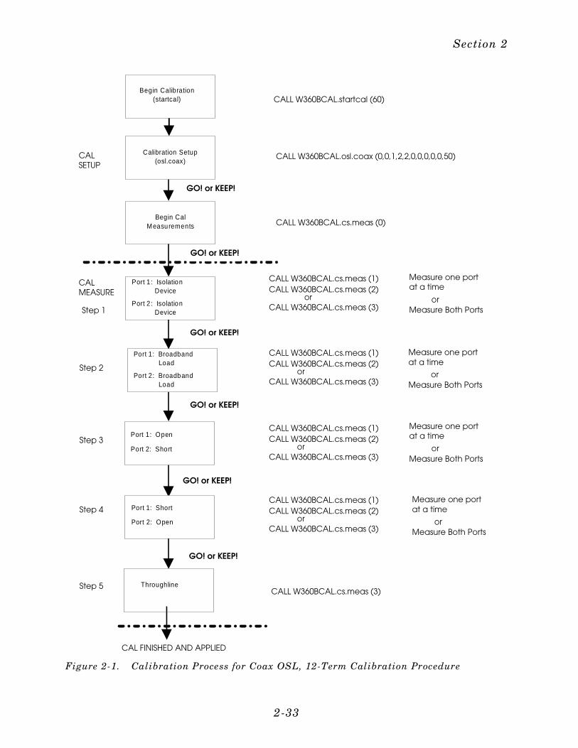
Once the calibration setup is complete, the Measure Cal Standards (cs.meas) panelmay be used to automate the calibration standard measurement process. You shouldfirst select “Begin Cal” followed by GO! or KEEP!. This will move the 360B from thecalibration setup to the calibration measurement mode. From this point, you can in-voke the Meas Port 1, Meas Port 2, Meas Both selections, as appropriate. It is impor-tant that you know which standards you are measuring at each step; this willdetermine which port(s) is selected for measurement. For more details, refer to Section3 and the cs.meas panel. Figure 2-1 (page 2-27) shows a calibration example of a Coax-ial OSL, 12-Term calibration process.
Section 2
2-31
Sub-Class Function Name Funct ion Syntax Page
None Start Cal ibration startcal 3-110
None Flat Power Calibrat ion ca l.pwr 3-10
Load Cal Kit Coeff ca l. load 3-8
Coaxial Cal
Offset-Short os.coax 3-46
Open- Short-Load osl.coax 3-56
LRL/LRM (coax) l r l . l ine 3-34
User-Def ined Coax udef.coax 3-114
Microstr ipCal
Offset-Short os.micro 3-50
Open- Short- Load osl.micro 3-60
LRL/LRM (microstr ip) l r l . l ine 3-38
User-Def ined Microstr ip udef .micro 3-116
WaveguideCal
Offset-Short os.wg 3-54
LRL/LRM (waveguide) l r l . l ine 3-42
User-Def ined Waveguid udef.wg 3-118
None Measure Cal Standards cs.meas 3-14
Table 2-2. Calibration Class Functions
360B LabWindows Driver User’s Guide
2-32
GO! or KEEP!
Calibration Setup (osl.coax)
Begin Cal Measurements
Port 1 : Isolation Device
Throughline
Port 2 : Isolation Device
Port 1: Broadband Load
Port 2: Broadband Load
Port 1: Open
Port 2: Short
Port 2: Open
Port 1: Short
GO! or KEEP!
GO! or KEEP!
GO! or KEEP!
GO! or KEEP!
GO! or KEEP!
CALL W360BCAL.cs.meas (0)
CALL W360BCAL.cs.meas (3)
Measure one portat a time
orMeasure Both Ports
Measure one portat a time
orMeasure Both Ports
Measure one portat a time
orMeasure Both Ports
Measure one portat a time
orMeasure Both Ports
CALSETUP
CALMEASURE
Step 1
Step 2
Step 3
Step 4
Step 5
CAL FINISHED AND APPLIED
Begin Calibration (startcal) CALL W360BCAL.startcal (60)
CALL W360BCAL.osl.coax (0,0,1,2,2,0,0,0,0,0,50)
or
CALL W360BCAL.cs.meas (1)CALL W360BCAL.cs.meas (2)
CALL W360BCAL.cs.meas (3)
CALL W360BCAL.cs.meas (1)CALL W360BCAL.cs.meas (2)
orCALL W360BCAL.cs.meas (3)
CALL W360BCAL.cs.meas (1)CALL W360BCAL.cs.meas (2)
orCALL W360BCAL.cs.meas (3)
CALL W360BCAL.cs.meas (2)CALL W360BCAL.cs.meas (1)
orCALL W360BCAL.cs.meas (3)
Figure 2-1. Calibration Process for Coax OSL, 12-Term Calibration Procedure
Section 2
2-33
Display Setup Class
This functional class sets up the 360B display format. The type of display is selectedwith the Channel Display Mode function. This function defines a single or multiplechannel display.
The Channel Definition function selects the channel, the S-Parameter, and the graphtype to be displayed. You can define a unique measurement ratio by selecting User De-fined S-parameter. You can also give this parameter a unique name, which is also en-tered in this function panel. The User Defined parameter label is limited to fivecharacters, maximum.
The next two functions, Cartesian Scale and Polar Scale, are used to scale the meas-ured data trace. The driver includes no provisions to ensure that you have made the cor-rect function choice. These two functions let you both select a channel and eitherautoscale or manually scale the display. Note, however, that autoscale must be posi-tioned to ’OFF’ to manually scale the data traces.
In the case of the Cartesian Scale function, you can input a group delay aperture. If aPolar or Smith Chart display is selected, you can enter scale factors from those listedin the Polar/Smith Scale panel.
The Smoothing function lets you apply smoothing to the current channel’s trace. Notethat smoothing is only allowed on certain formats and S-Parameters. Refer to theModel 360B Vector Network Analyzer Operation Manual for a description of S-Parame-ters and vector network analyzer basics.
Sub-Class Function Name Funct ion Syntax Page
None Channel Display Mode set.vnad 3-92
Channel Def init ion set.chdef 3-70
Cartesian Scale set.scc 3-76
Polar/Smith Scale set.scp 3-78
Smoothing set.smooth 3-80
Table 2-3. Display Setup Class Functions
360B LabWindows Driver User’s Guide
2-34

Data Analysis Class
MARKER FUNCTIONS:
This functional class lets you set and read values for selected markers. You must spec-ify the channel and the marker to be used (1-6). In all cases, except the set markersfunction, the results of the marker setting are returned to the current panel. The re-turns are for both of the complex data values, regardless of current channel format. Allvalues are returned in an ASCII format.
The Set Marker function lets you turn any or all of the markers on or off. If you set amarker on, a frequency should also be entered. If no frequency is entered, the selectedmarker will still become active and go to a default frequency value. The markers areset for all of the channels currently being displayed.
The Read Marker function reads (gets) the values of all markers. You select the chan-nel from which to retrieve the marker information. All marker values are returned. Azero value is returned for any inactive markers.
The Search Min/Max function lets you perform a marker search routine for either themaximum or minimum trace values. You select the channel, the marker, and the searchfunction (Max or Min). The function returns the marker frequency/time and the realand imaginary values.
TRACE DATA FUNCTIONS:
These functions let you save trace data to the 360B internal channel-based memory reg-isters. Trace manipulation is also available using the standard math function +, –, /,and *.
The Data To Mem selection on the Math Function panel lets you save trace data to the360B RAM for the selected channel. The Math Function panel also lets you perform se-lected math functions for trace manipulation. This function also lets you specify the dis-play for the current channel. Note: There must be a saved trace in the selected channelfor the math functions to work properly.
LIMIT FUNCTIONS:
The Limits function lets you set limit lines for the 360B display. You must know thecurrent display format in order to set the appropriate limit values.
The Set Limits function lets you turn limit lines on or off. You must select the channelwhere the limits are to be displayed, then enter an upper and a lower limit. The en-tered limit values will be displayed. In the case of a complex display, limits can be en-tered for the imaginary data as well. You must select phase or imaginary units,depending on the current display format.
TIME DOMAIN FUNCTIONS:
These functions let you view responses in the time domain. The time domain optionmust be installed as part of the 360B operating system. The time domain functions letyou perform digital processing operations and set start/stop times and time domaingates. The Domain Selection function lets you select the channel for which the time do-main transform is to be performed. You can then select time or distance to be the verti-cal scale, and a bandpass, impulse, or step response.
Section 2
2-35

The window function is also selected in this function panel. If a step or impulse re-sponse is chosen, you must enter the DC term for the transform. Refer to the Model360B Operation Manual for a thorough discussion of the time domain function.
The Start/Stop Time function lets you set the start and stop time or distance. These pa-rameters are applied to the active channel.
The Set Gate function controls the setting of the time domain gate feature. You selectwhether the gate should be turned on or off, and whether the gate symbols should bedisplayed. You can select the format for the entered gate values: Start/Stop or Cen-ter/Span. The gate is applied to the active channel.
Sub-Class Function Name Funct ion Syntax Page
MarkerFunct ions
Read Markers get .mark 3-24
Search Min/Max set.srch 3-82
Set Markers set.mark 3-74
TraceData Funct ions
Math Funct ions tdf .math 3-112
Limit Funct ions
Set Limi ts da. l im 3-16
TimeDomainFunct ions
Domain Select ion set. td 3-84
Set Gate set. tdg 3-86
Start /Stop Time set. tdt 3-88
Table 2-4. Marker Functions
360B LabWindows Driver User’s Guide
2-36
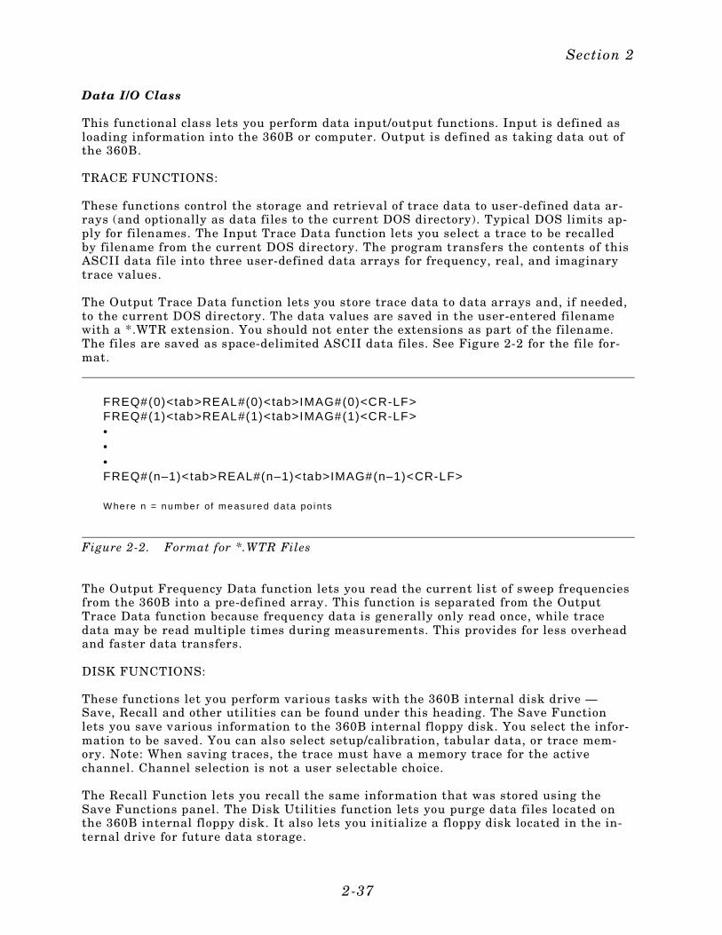
Data I/O Class
This functional class lets you perform data input/output functions. Input is defined asloading information into the 360B or computer. Output is defined as taking data out ofthe 360B.
TRACE FUNCTIONS:
These functions control the storage and retrieval of trace data to user-defined data ar-rays (and optionally as data files to the current DOS directory). Typical DOS limits ap-ply for filenames. The Input Trace Data function lets you select a trace to be recalledby filename from the current DOS directory. The program transfers the contents of thisASCII data file into three user-defined data arrays for frequency, real, and imaginarytrace values.
The Output Trace Data function lets you store trace data to data arrays and, if needed,to the current DOS directory. The data values are saved in the user-entered filenamewith a *.WTR extension. You should not enter the extensions as part of the filename.The files are saved as space-delimited ASCII data files. See Figure 2-2 for the file for-mat.
The Output Frequency Data function lets you read the current list of sweep frequenciesfrom the 360B into a pre-defined array. This function is separated from the OutputTrace Data function because frequency data is generally only read once, while tracedata may be read multiple times during measurements. This provides for less overheadand faster data transfers.
DISK FUNCTIONS:
These functions let you perform various tasks with the 360B internal disk drive —Save, Recall and other utilities can be found under this heading. The Save Functionlets you save various information to the 360B internal floppy disk. You select the infor-mation to be saved. You can also select setup/calibration, tabular data, or trace mem-ory. Note: When saving traces, the trace must have a memory trace for the activechannel. Channel selection is not a user selectable choice.
The Recall Function lets you recall the same information that was stored using theSave Functions panel. The Disk Utilities function lets you purge data files located onthe 360B internal floppy disk. It also lets you initialize a floppy disk located in the in-ternal drive for future data storage.
FREQ#(0)<tab>REAL#(0)<tab>IMAG#(0)<CR-LF>FREQ#(1)<tab>REAL#(1)<tab>IMAG#(1)<CR-LF>•••FREQ#(n–1)<tab>REAL#(n–1)<tab>IMAG#(n–1)<CR-LF>
W he re n = n u m be r of m e asu re d d at a po i n t s
Figure 2-2. Format for *.WTR Files
Section 2
2-37
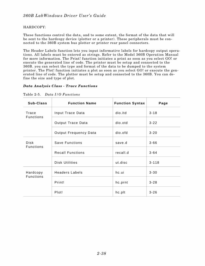
HARDCOPY:
These functions control the data, and to some extent, the format of the data that willbe sent to the hardcopy device (plotter or a printer). These peripherals must be con-nected to the 360B system bus plotter or printer rear panel connectors.
The Header Labels function lets you input informative labels for hardcopy output opera-tions. All labels must be entered as strings. Refer to the Model 360B Operation Manualfor more information. The Print! function initiates a print as soon as you select GO! orexecute the generated line of code. The printer must be setup and connected to the360B. you can select the type and format of the data to be dumped to the systemprinter. The Plot! function initiates a plot as soon as you select GO! or execute the gen-erated line of code. The plotter must be setup and connected to the 360B. You can de-fine the size and type of plot.
Data Analysis Class - Trace Functions
Sub-Class Funct ion Name Function Syntax Page
TraceFunct ions
Input Trace Data dio.i td 3-18
Output Trace Data dio.otd 3-22
Output Frequency Data dio.ofd 3-20
DiskFunct ions
Save Functions save.d 3-66
Recal l Funct ions recal l .d 3-64
Disk Ut i l i t ies ut .d isc 3-118
HardcopyFunct ions
Headers Labels hc.ui 3-30
Print ! hc.prnt 3-28
Plot ! hc.plt 3-26
Table 2-5. Data I/O Functions
360B LabWindows Driver User’s Guide
2-38
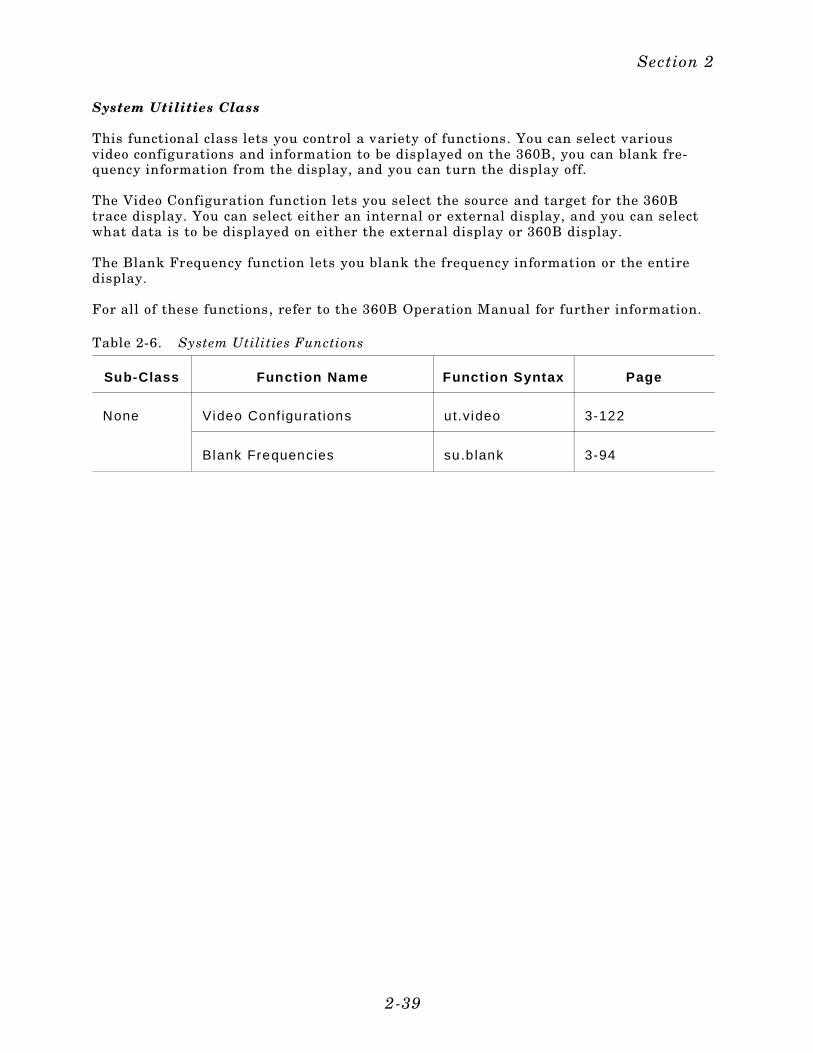
System Utilities Class
This functional class lets you control a variety of functions. You can select variousvideo configurations and information to be displayed on the 360B, you can blank fre-quency information from the display, and you can turn the display off.
The Video Configuration function lets you select the source and target for the 360Btrace display. You can select either an internal or external display, and you can selectwhat data is to be displayed on either the external display or 360B display.
The Blank Frequency function lets you blank the frequency information or the entiredisplay.
For all of these functions, refer to the 360B Operation Manual for further information.
Sub-Class Function Name Funct ion Syntax Page
None Video Conf igurat ions ut.video 3-122
Blank Frequencies su.b lank 3-94
Table 2-6. System Utilities Functions
Section 2
2-39
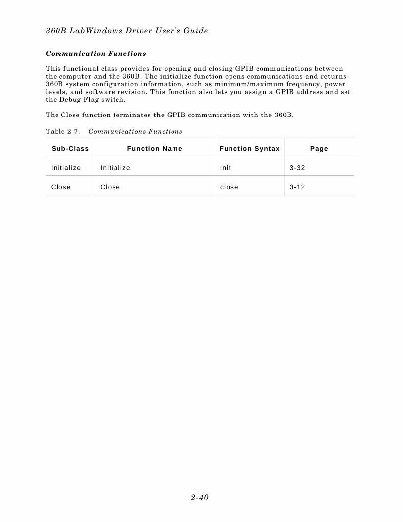
Communication Functions
This functional class provides for opening and closing GPIB communications betweenthe computer and the 360B. The initialize function opens communications and returns360B system configuration information, such as minimum/maximum frequency, powerlevels, and software revision. This function also lets you assign a GPIB address and setthe Debug Flag switch.
The Close function terminates the GPIB communication with the 360B.
Sub-Class Function Name Funct ion Syntax Page
Ini t ial ize Ini tial ize ini t 3-32
Close Close close 3-12
Table 2-7. Communications Functions
360B LabWindows Driver User’s Guide
2-40

Section 3Driver References
Section 3Driver References
Introduction
This section lists all the 360B Instrument Driver function panel routines in alphabetical order.
Function Panel Descriptions
The 360B LabWindows Driver contains 49 panels that provide an intuitive method forcoding instrument functions. Figure 3-1 shows the hierachial structure of the func-tional panels. Table 3-1 lists these panels and shows the page number on which theyare described.
Global and Local Variables
Table 3-2 provides a listing of the global and local variables used by the 360B driver.
3-3
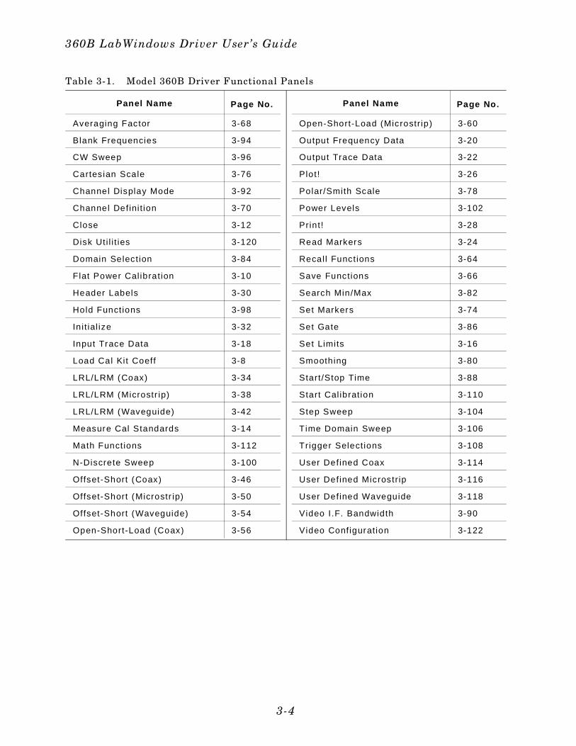
Panel Name Page No.
Averaging Factor 3-68
Blank Frequencies 3-94
CW Sweep 3-96
Cartesian Scale 3-76
Channel Display Mode 3-92
Channel Defini t ion 3-70
Close 3-12
Disk Uti l i t ies 3-120
Domain Selection 3-84
Flat Power Cal ibrat ion 3-10
Header Labels 3-30
Hold Functions 3-98
Init ial ize 3-32
Input Trace Data 3-18
Load Cal Kit Coeff 3-8
LRL/LRM (Coax) 3-34
LRL/LRM (Microstr ip) 3-38
LRL/LRM (Waveguide) 3-42
Measure Cal Standards 3-14
Math Functions 3-112
N-Discrete Sweep 3-100
Offset-Short (Coax) 3-46
Offset-Short (Microstr ip) 3-50
Offset-Short (Waveguide) 3-54
Open-Short-Load (Coax) 3-56
Panel Name Page No.
Open-Short-Load (Microstr ip) 3-60
Output Frequency Data 3-20
Output Trace Data 3-22
Plot! 3-26
Polar/Smith Scale 3-78
Power Levels 3-102
Print! 3-28
Read Markers 3-24
Recal l Funct ions 3-64
Save Functions 3-66
Search Min/Max 3-82
Set Markers 3-74
Set Gate 3-86
Set Limits 3-16
Smoothing 3-80
Start/Stop Time 3-88
Start Cal ibrat ion 3-110
Step Sweep 3-104
Time Domain Sweep 3-106
Trigger Selections 3-108
User Defined Coax 3-114
User Defined Microstr ip 3-116
User Defined Waveguide 3-118
Video I.F. Bandwidth 3-90
Video Configuration 3-122
Table 3-1. Model 360B Driver Functional Panels
360B LabWindows Driver User’s Guide
3-4
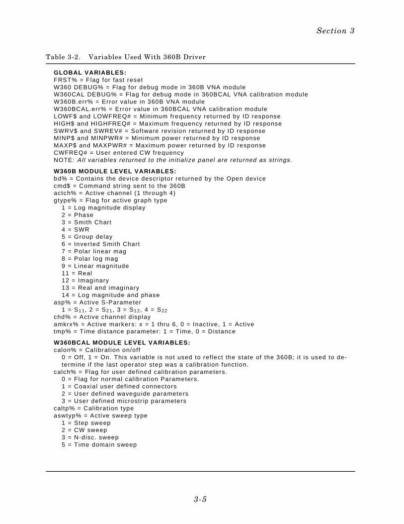
GLOBAL VARIABLES:FRST% = Flag for fast resetW360 DEBUG% = Flag for debug mode in 360B VNA moduleW360CAL DEBUG% = Flag for debug mode in 360BCAL VNA cal ibrat ion moduleW360B.err% = Error value in 360B VNA moduleW360BCAL.err% = Error value in 360BCAL VNA cal ibrat ion moduleLOWF$ and LOWFREQ# = Minimum frequency returned by ID responseHIGH$ and HIGHFREQ# = Maximum frequency returned by ID responseSWRV$ and SWREV# = Software revision returned by ID responseMINP$ and MINPWR# = Minimum power returned by ID responseMAXP$ and MAXPWR# = Maximum power returned by ID responseCWFREQ# = User entered CW frequencyNOTE: Al l variables returned to the in i t ial ize panel are returned as str ings.
W360B MODULE LEVEL VARIABLES:bd% = Contains the device descr iptor returned by the Open devicecmd$ = Command str ing sent to the 360Bactch% = Active channel (1 through 4)gtype% = Flag for act ive graph type
1 = Log magnitude display 2 = Phase 3 = Smith Chart 4 = SWR 5 = Group delay 6 = Inverted Smith Chart 7 = Polar l inear mag 8 = Polar log mag 9 = Linear magnitude 11 = Real 12 = Imaginary 13 = Real and imaginary 14 = Log magnitude and phase
asp% = Active S-Parameter 1 = S11, 2 = S21, 3 = S12, 4 = S22
chd% = Active channel d isplayamkrx% = Active markers: x = 1 thru 6, 0 = Inactive, 1 = Activetmp% = Time distance parameter: 1 = Time, 0 = Distance
W360BCAL MODULE LEVEL VARIABLES:calon% = Calibrat ion on/off
0 = Off, 1 = On. This variable is not used to ref lect the state of the 360B; i t is used to de-termine i f the last operator step was a cal ibrat ion function.
calch% = Flag for user defined cal ibrat ion parameters. 0 = Flag for normal cal ibrat ion Parameters. 1 = Coaxial user defined connectors 2 = User defined waveguide parameters 3 = User defined microstr ip parameters
caltp% = Cal ibrat ion typeaswtyp% = Active sweep type
1 = Step sweep 2 = CW sweep 3 = N-disc. sweep 5 = Time domain sweep
Table 3-2. Variables Used With 360B Driver
Section 3
3-5
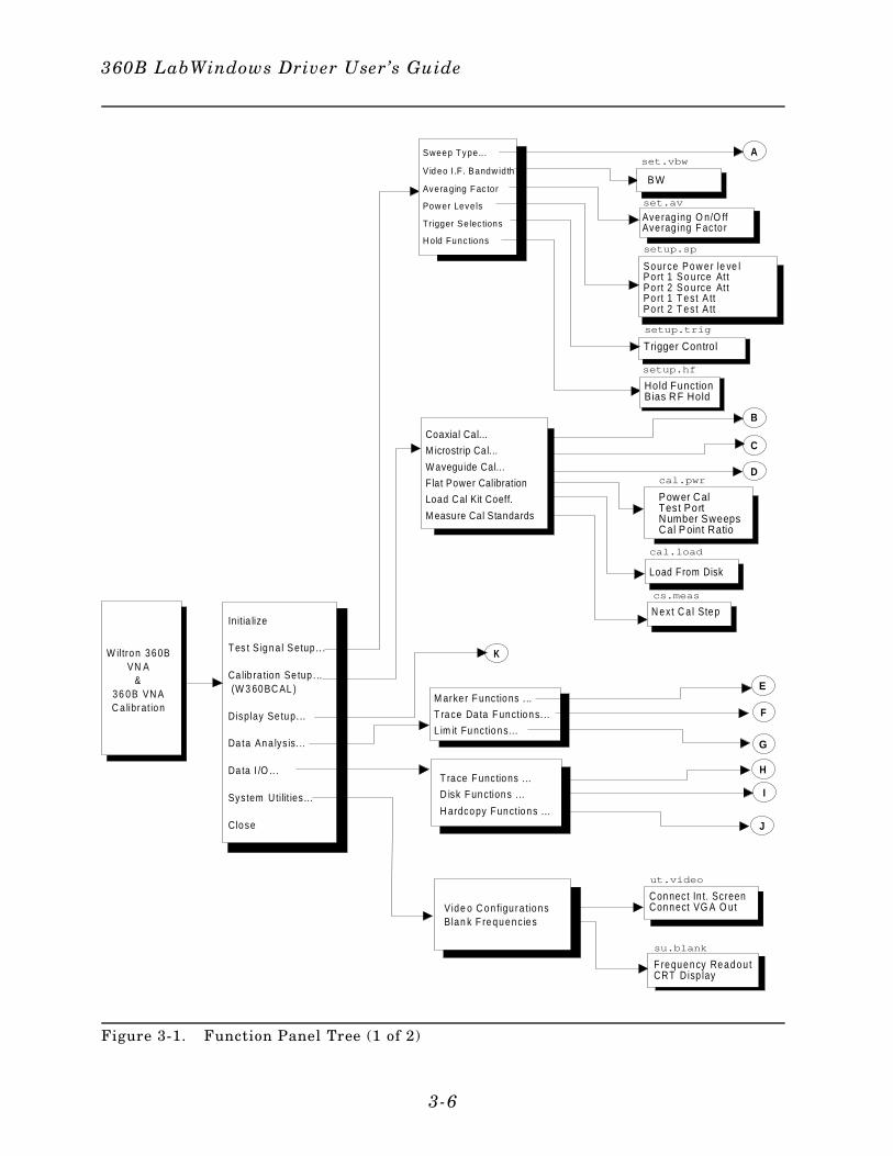
W iltron 360BVN A
&36 0B VN AC a librat ion
Initia lize
T es t S igna l Setup .. .
Ca lib ra tion Se tup . .. (W 3 60BC AL )
Display Se tup. ..
Da ta Ana lys is. ..
Da ta I /O .. .
System Uti lit ies ...
Close
set.av
A
B
C
D
F
G
H
I
J
M arke r F unctions . ..
T race Da ta F unct ions. ..
L im it Functions...
E
K
Avera ging F ac tor
Pow er Levels
Trigger Selec tions
V id eo I .F. Bandw idth
Sweep T ype.. .
H old Func tions
setup.trig
Trigger Control
setup.sp
S o urce P o w er le ve lP o rt 1 S o u rce At tP o rt 2 S o u rce At tP o rt 1 T est A ttP o rt 2 T est A tt
su.blank
F requency Readou tCRT D isp lay
ut.video
Connect In t. ScreenConnect VG A O ut
cs.meas
N ext C a l Step
cal.load
Load From Disk
cal.pwr
Power CalTest PortNumber SweepsCal P oint Ratio
setup.hf
Hold FunctionBias RF Hold
Ave rag ing O n/O ffAve rag ing F acto r
BW
set.vbw
Coaxial Cal...
M icrostrip Cal...
Waveguide Cal...
F lat Power Calibration
Load Cal Kit Coeff.
M easure Cal Standards
T race F unctions . ..
D isk F unctions . ..
H ardcopy Funct ions ...
Vide o C on figu ra tionsBlan k F requenc ies
Figure 3-1. Function Panel Tree (1 of 2)
360B LabWindows Driver User’s Guide
3-6
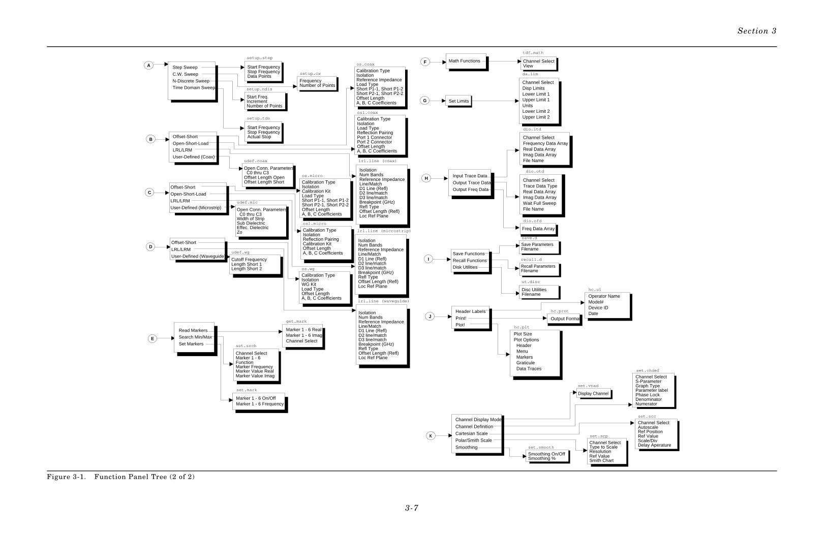
dio.itd
Channel SelectFrequency Data ArrayReal Data ArrayImag Data ArrayFile Name
Channel SelectTrace Data TypeReal Data ArrayImag Data ArrayWait Full SweepFile Name
dio.otd
recall.d
Recall ParametersFilename
udef.coax
Open Conn. Parameters C0 thru C3Offset Length OpenOffset Length Short
setup.step
Start FrequencyStop FrequencyData Points
setup.cw
FrequencyNumber of Points
da.lim
Channel SelectDisp LimitsLower Limit 1Upper Limit 1UnitsLower Limit 2Upper Limit 2
Save Functions
Recall Functions
Disk Utilities
Channel Display Mode
Channel Definition
Cartesian Scale
Polar/Smith Scale
Smoothing
Offset-Short
Open-Short-Load
LRL/LRM
User-Defined (Microstrip)
Offset-Short
LRL/LRM
User-Defined (Waveguide)
Offset-Short
Open-Short-Load
LRL/LRM
User-Defined (Coax)
B
A
C
D
E
F
H
I
Header Labels
Print!
Plot!
J
setup.ndis
Start Freq.IncrementNumber of Points
setup.tds
Start FrequencyStop FrequencyActual Stop
os.coax
Calibration TypeIsolationReference ImpedanceLoad TypeShort P1-1, Short P1-2Short P2-1, Short P2-2Offset LengthA, B, C Coefficients
os.micro
Calibration TypeIsolationCalibration KitLoad TypeShort P1-1, Short P1-2Short P2-1, Short P2-2Offset LengthA, B, C Coefficients
osl.coax
Calibration TypeIsolationLoad TypeReflection PairingPort 1 ConnectorPort 2 ConnectorOffset LengthA, B, C Coefficients
osl.micro
Calibration TypeIsolationReflection PairingCalibration KitOffset LengthA, B, C Coefficients
os.wg
Calibration TypeIsolationWG KitLoad TypeOffset LengthA, B, C Coefficients
udef.mic
Open Conn. Parameters C0 thru C3Width of StripSub DielectricEffec. DielectricZo
udef.wg
Cutoff FrequencyLength Short 1Length Short 2
get.mark
Marker 1 - 6 RealMarker 1 - 6 ImagChannel Select
set.mark
Marker 1 - 6 On/OffMarker 1 - 6 Frequency
set.srch
Channel SelectMarker 1 - 6FunctionMarker FrequencyMarker Value RealMarker Value Imag
tdf.math
Channel SelectView
@ Set LimitsG
@
set.smooth
Smoothing On/OffSmoothing %
set.scc
Channel SelectAutoscaleRef PositionRef ValueScale/DivDelay Aperature
set.scp
Channel SelectType to ScaleResolutionRef ValueSmith Chart
set.vnad
Display Channel
K
save.d
Save ParametersFilename
hc.prnt
Output Format
hc.plt
hc.ui
Operator NameModel#Device IDDate
Step Sweep
C.W. Sweep
N-Discrete Sweep
Time Domain Sweep
Read Markers
Search Min/Max
Set Markers
lrl.line (waveguide)
IsolationNum BandsReference ImpedanceLine/MatchD1 Line (Refl)D2 line/matchD3 line/matchBreakpoint (GHz)Refl TypeOffset Length (Refl)Loc Ref Plane
lrl.line (coax)
IsolationNum BandsReference ImpedanceLine/MatchD1 Line (Refl)D2 line/matchD3 line/matchBreakpoint (GHz)Refl TypeOffset Length (Refl)Loc Ref Plane
lrl.line (microstrip)
IsolationNum BandsReference ImpedanceLine/MatchD1 Line (Refl)D2 line/matchD3 line/matchBreakpoint (GHz)Refl TypeOffset Length (Refl)Loc Ref Plane
Math Functions
Input Trace Data
Output Trace Data
Output Freq Data
Freq Data Array
dio.ofd
ut.disc
Disc UtilitiesFilename
Plot SizePlot Options Header Menu Markers Graticule Data Traces set.chdef
Channel SelectS-ParameterGraph TypeParameter labelPhase LockDenominatorNumerator
Figure 3-1. Function Panel Tree (2 of 2)
Section 3
3-7

cal. load
Function Panel Name: Load Cal Kit Coeff(icients)
Description: This function loads the coefficient data for the calibra-tion components from a floppy disk.
Controls:
Load From Disk On/Off:
Lets users turn the Load From Disk function on or off.
360B LabWindows Driver User’s Guide
3-8
Input Parameters: (D) is default setting.
Var iableName
Var iableType Descript ion Detai ls
ST% Integer Load cal ibrat ion data from disk 0 = Off (D)1 = On
Output Parameters: None.
Error: LabWindows error codes(220-300). W360BCAL errorcodes.
Program Examples:
Quick BASIC:
REM Turns the calibrat ion data “Load From Disk” funct ion on or of f.
CALL W360BCAL.cal . load (ST%)
Microsoft C:
/ * Turns the cal ibration data “Load From Disk” funct ion on or of f . * /
W360BCAL_cal_load (ST)
Section 3
3-9
cal.pwr (360B only)
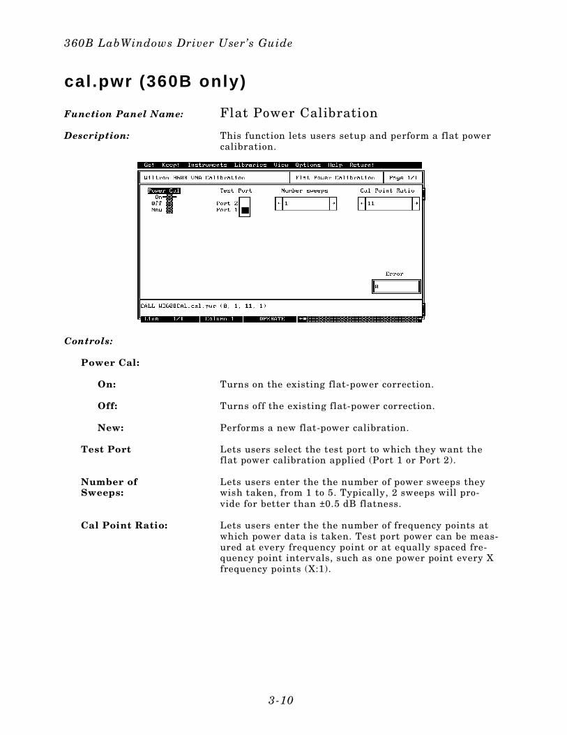
Function Panel Name: Flat Power Calibration
Description: This function lets users setup and perform a flat powercalibration.
Controls:
Power Cal:
On: Turns on the existing flat-power correction.
Off: Turns off the existing flat-power correction.
New: Performs a new flat-power calibration.
Test Port Lets users select the test port to which they want theflat power calibration applied (Port 1 or Port 2).
Number of Sweeps:
Lets users enter the the number of power sweeps theywish taken, from 1 to 5. Typically, 2 sweeps will pro-vide for better than ±0.5 dB flatness.
Cal Point Ratio: Lets users enter the the number of frequency points atwhich power data is taken. Test port power can be meas-ured at every frequency point or at equally spaced fre-quency point intervals, such as one power point every Xfrequency points (X:1).
360B LabWindows Driver User’s Guide
3-10
Input Parameters: (D) is default setting.
Var iableName
Var iableType Descript ion Detai ls Range
TP% Integer Test Port 0 = Port 1 (D) 1 = Port 2
NUMSW% Integer Number of sweeps to average 1 (D) 1 to 5
DPTS% Integer Number of skipped data points 11 (D) 11 thru500, atpresetincrements
ONF% Integer Flat power cal on/off 0 = On (D)1 = Off2 = New
Output Parameters: None.
Error: LabWindows error codes(220-300). W360BCAL errorcodes
Program Examples:
Quick BASIC:
REM Assign flat power correct ion va lues to test port .
CALL W360BCAL.cal .pwr (TP%,NUMSW%,DPTS%,ONF%)
Microsoft C:
/ * Assign f lat power correct ion values to test port . */
W360BCAL_cal_pwr (TP,NUMSW,DPTS,ONF)
Section 3
3-11
close
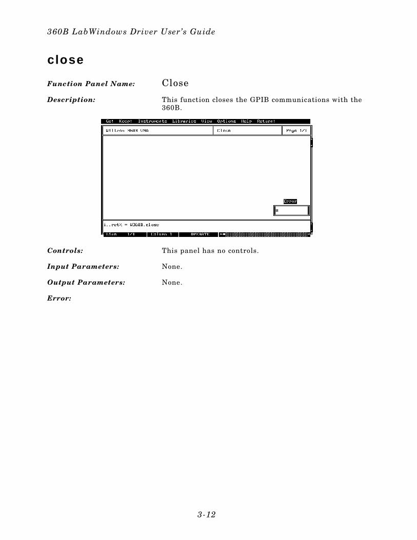
Function Panel Name: Close
Description: This function closes the GPIB communications with the360B.
Controls: This panel has no controls.
Input Parameters: None.
Output Parameters: None.
Error:
360B LabWindows Driver User’s Guide
3-12

Program Examples:
Quick BASIC:
REM Close the 360B Instrument Driver.
CALL W360B.close()or
i .. ret% = W360BCAL.close()
Microsoft C:
/ * Close the 360B Instrument Driver. */
W360B_close()or
i_ret = W360BCAL_close()
Section 3
3-13

cs.meas
Function Panel Name: Measure Cal(ibration) Standards
Description: This function lets users measure the calibrationstandard(s) for the specified calibration. This should becompleted immediately following the calibration setupfunction.
Controls:
Next Cal Step:
Begin Cal: Starts the calibration measurement sequence. This isperformed after calibration setup.
Meas Port 1:(360B only)
Measures the Port 1 device only. Used only for one-portdevices, such as Opens and Shorts. This selection isonly valid during calibration steps that provide the op-tion: PRESS <1> FOR PORT 1 DEVICE.
Meas Port 2:(360B only)
Measures the Port 2 device only. Used only for one-portdevices, such as Opens and Shorts. This selection isonly valid during calibration steps that provide the op-tion: PRESS <2> FOR PORT 2 DEVICE.
360B LabWindows Driver User’s Guide
3-14
Meas Both: Measures both Port 1 and Port 2 devices without paus-ing between steps. This should be the default selectionat each point in the calibration measurement sequence.
Input Parameters: (D) is the default setting.
Var iableName
Var iableType Descript ion Detai ls
CSTP% Integer Cal ibrat ion step 0 = begin cal sequence(D). No data is taken 1 = Take cal data por t 1 2 = Take cal data por t 2 3 = Take cal data both portsNOTE: I f function doesn’t return or VNA does not start measuring device, then the wrong cal ibrat ion step was choosen. Press Ctr l + Break keys and select the cor rect cal l step.
Output Parameters: None.
Error: LabWindows error codes(220-300). W360BCAL errorcodes.
Program Examples:
Quick BASIC:
REM Get the cal ibrat ion standards.
CALL W360BCAL.cs.meas (CSTP%)
Microsoft C:
/ * Get the ca librat ion standards. * /
W360BCAL_cs_meas (CSTP)
Section 3
3-15

da. l im
Function Panel Name: Set Limits
Description: This function lets users set and display limit lines.
Controls:
Channel Select: Lets users select the channel on which the limit lineswill be displayed.
Disp Limits: Lets users turn the limit display on or off.
Lower Limit 1: Lets users set a value for the lower limit line.
Upper Limit 1: Lets users set a value for the upper limit line.
Units: Lets users optionally select the type of display units forthe phase/imaginary portions of complex displays (suchas log magnitude and phase, linear magnitude andphase, etc).
Off: Turns off the units selection.
Phase (Deg.): Select degrees for a display of phase.
Imaginary: Selects imaginary units.
Lower Limit 2: Lets users set a value for the lower limit line.
Upper Limit 2: Lets users set a value for the upper limit line.
360B LabWindows Driver User’s Guide
3-16
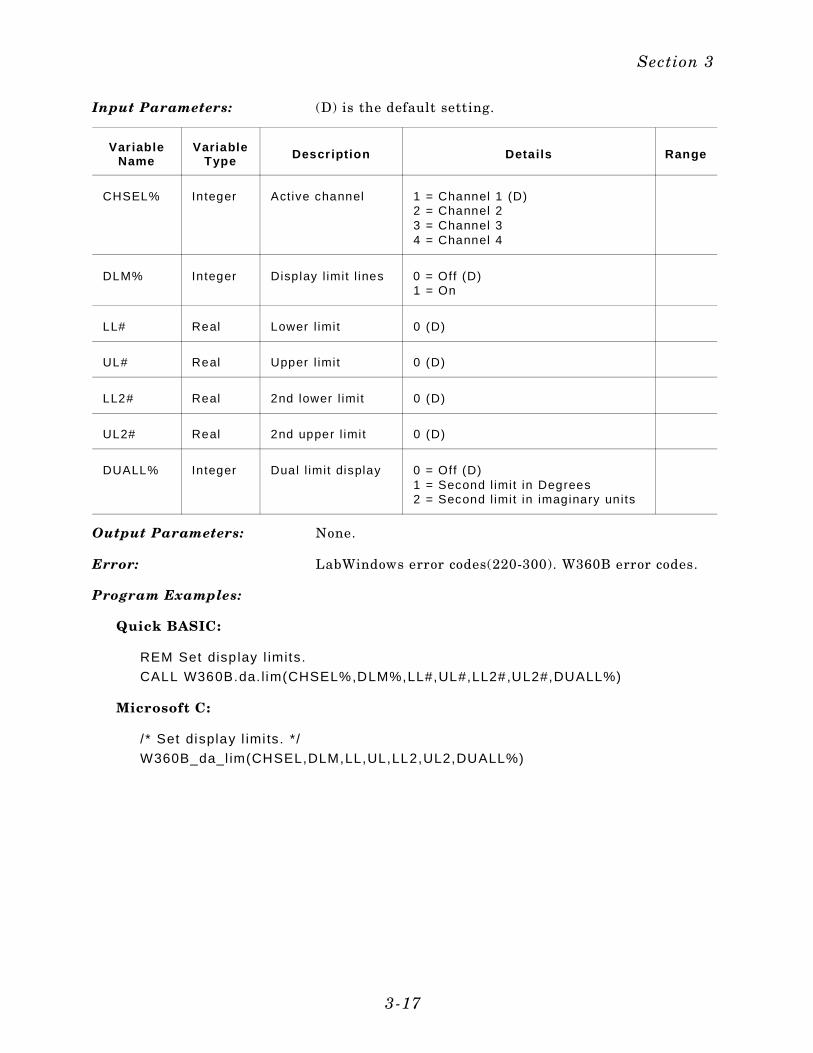
Input Parameters: (D) is the default setting.
Var iableName
VariableType Descr ipt ion Detai ls Range
CHSEL% Integer Active channel 1 = Channel 1 (D)2 = Channel 23 = Channel 34 = Channel 4
DLM% Integer Display l imit l ines 0 = Off (D) 1 = On
LL# Real Lower l imit 0 (D)
UL# Real Upper l imit 0 (D)
LL2# Real 2nd lower l imit 0 (D)
UL2# Real 2nd upper l imit 0 (D)
DUALL% Integer Dual l imit display 0 = Off (D)1 = Second l imit in Degrees 2 = Second l imit in imaginary units
Output Parameters: None.
Error: LabWindows error codes(220-300). W360B error codes.
Program Examples:
Quick BASIC:
REM Set disp lay l imits.
CALL W360B.da. l im(CHSEL%,DLM%,LL#,UL#,LL2#,UL2#,DUALL%)
Microsoft C:
/ * Set display l imi ts. */
W360B_da_l im(CHSEL,DLM,LL,UL,LL2,UL2,DUALL%)
Section 3
3-17
dio. i td
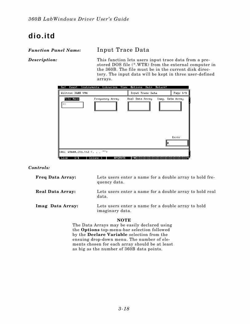
Function Panel Name: Input Trace Data
Description: This function lets users input trace data from a pre-stored DOS file (*.WTR) from the external computer inthe 360B. The file must be in the current disk direc-tory. The input data will be kept in three user-definedarrays.
Controls:
Freq Data Array: Lets users enter a name for a double array to hold fre-quency data.
Real Data Array: Lets users enter a name for a double array to hold realdata.
Imag Data Array: Lets users enter a name for a double array to holdimaginary data.
NOTEThe Data Arrays may be easily declared usingthe Options top-menu-bar selection followedby the Declare Variable selection from theensuing drop-down menu. The number of ele-ments chosen for each array should be at leastas big as the number of 360B data points.
360B LabWindows Driver User’s Guide
3-18
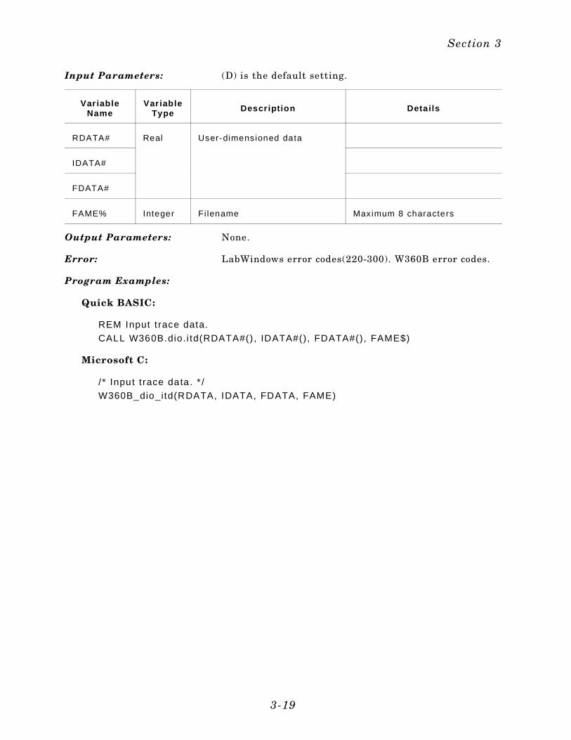
Input Parameters: (D) is the default setting.
Var iableName
Var iableType Descr ipt ion Detai ls
RDATA# Real User-dimensioned data
IDATA#
FDATA#
FAME% Integer Fi lename Maximum 8 characters
Output Parameters: None.
Error: LabWindows error codes(220-300). W360B error codes.
Program Examples:
Quick BASIC:
REM Input t race data.
CALL W360B.dio .i td(RDATA#(), IDATA#(), FDATA#(), FAME$)
Microsoft C:
/ * Input t race data. * /
W360B_dio_itd(RDATA, IDATA, FDATA, FAME)
Section 3
3-19
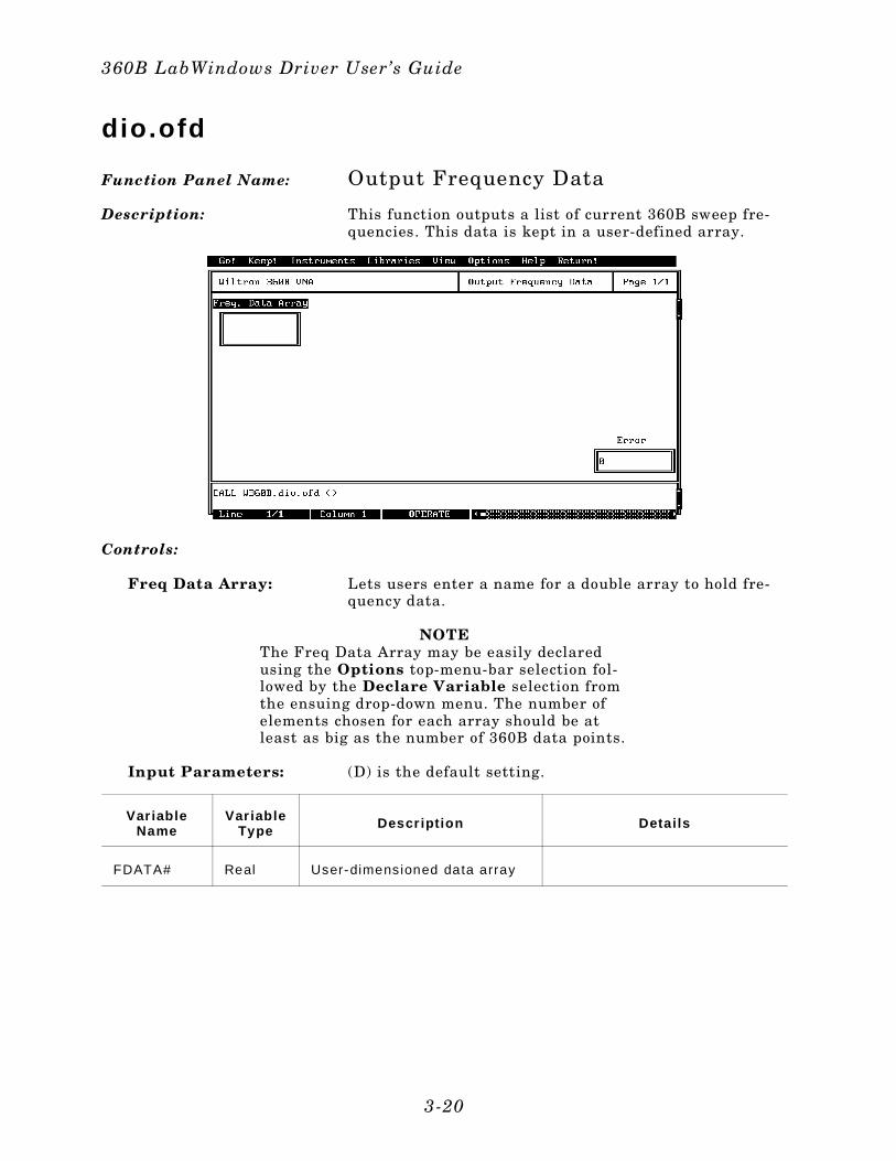
dio.ofd
Function Panel Name: Output Frequency Data
Description: This function outputs a list of current 360B sweep fre-quencies. This data is kept in a user-defined array.
Controls:
Freq Data Array: Lets users enter a name for a double array to hold fre-quency data.
NOTEThe Freq Data Array may be easily declaredusing the Options top-menu-bar selection fol-lowed by the Declare Variable selection fromthe ensuing drop-down menu. The number ofelements chosen for each array should be atleast as big as the number of 360B data points.
Input Parameters: (D) is the default setting.
Var iableName
Var iableType Descr ipt ion Detai ls
FDATA# Real User-dimensioned data array
360B LabWindows Driver User’s Guide
3-20
Input Parameters: None
Output Parameters: None.
Error: LabWindows error codes(220-300). W360B error codes.
Program Examples:
Quick BASIC:
REM Input t race data.
CALL W360B.dio .ofd(FDATA#())
Microsoft C:
/ * Input t race data. * /
W360B_dio_ofd(FDATA())
Section 3
3-21

dio.otd
Function Panel Name: Output Trace Data
Description: This function lets users output a data trace from the360B and place it into two user-defined arrays. Thetrace data may also be stored to the user-specified file-name (*.WTR) in the external computer’s current diskdirectory.
Controls:
Channel Select: Lets users select the channel from which the trace datawill be output.
Data Type:
Corrected: Data will be output in error-corrected real, imaginaryformat.
Final: Data will be output in error-corrected final displayformat.
Raw: Data will be output in non-error-corrected real, imagi-nary format.
Filename: Lets uses enter a file name for their data. If no file-name is entered, data is not saved to disk.
Real Data Array: Lets users select enter a name for an array to hold realdata.
360B LabWindows Driver User’s Guide
3-22
Imag Data Array: Lets users select enter a name for an array to holdimaginary data.
Wait Full Sweep:Yes/No
If “Yes” is selected, the 360B will take one completesweep before outputting trace data. This will ensurevalid data. However, if the trace data is already valid,this extra sweep can be avoided by selecting “No.”
Input Parameters: (D) is the default setting.
Var iableName
Var iableType Descr ipt ion Detai ls
CHSEL% Integer Selects active channel. 1 = CH1 (D)2 = CH23 = CH34 = CH4
FAME$ Str ing Fi lename Maximum 8 characters
DTYP% Integer Data type: Corrected or f inal 1 = Corrected (D)2 = Final3 = Raw
RDATA# Real User-dimensioned data
IDATA# Real
WFS% Integer Wait Ful l Sweep Flag 0 = No1 = Yes
Output Parameters: None.
Error: LabWindows error codes(220-300). W360B error codes.
Program Examples:
Quick BASIC:
REM Output t race data.
CALL W360B.dio .otd(RDATA#(), IDATA#(),CHSEL%,FAME$,DTYP%,WFS%)
Microsoft C:
/ * Output trace data. */
W360B_dio_otd(RDATA(), IDATA(),CHSEL,FAME,DTYP,WFS)
Section 3
3-23
get.mark
Function Panel Name: Read Markers
Description: This function lets users read the values for all markersset by Set Markers or Search Min/Max functions. All in-active markers return zeros.
Controls:
Marker n Real: Returns the Marker n Real value.
Marker n Imag: Returns the Marker n Imaginary value.
Channel Select: Lets users select the active channel that contains thedesired marker output information.
360B LabWindows Driver User’s Guide
3-24
Input Parameters: (D) is the default setting.
Var iableName
Var iableType Descript ion Detai ls
CHSEL% Integer Active channel 1 = Channel 1 (D)2 = Channel 23 = Channel 34 = Channel 4
MKV1# thruMKV6#
Real Returned values for real markers1 thru 6.
MKVI1#thruMKVI6#
Real Returned values for imaginarymarkers 1 thru 6.
Output Parameters: None.
Error: LabWindows error codes(220-300). W360B error codes.
Program Examples:
Quick BASIC:
REM Get the value of up to six rea l and imaginary markers.
CALL W360B.get .mark(CHSEL%, MKV1#,MKV2#,MKV3#,MKV4#,MKV5#,MKV6#,MK1I#,MK2I#,MK3I#,MK4I#,MK5I#,MK6I#)
Microsoft C:
/ * Get the va lue of up to six real and imaginary markers. */
W360B_get_mark(CHSEL, MKV1,MKV2,MKV3,MKV4,MKV5,MKV6,MK1I,MK2I,MK3I,MK4I,MK5I,MK6I)
Section 3
3-25
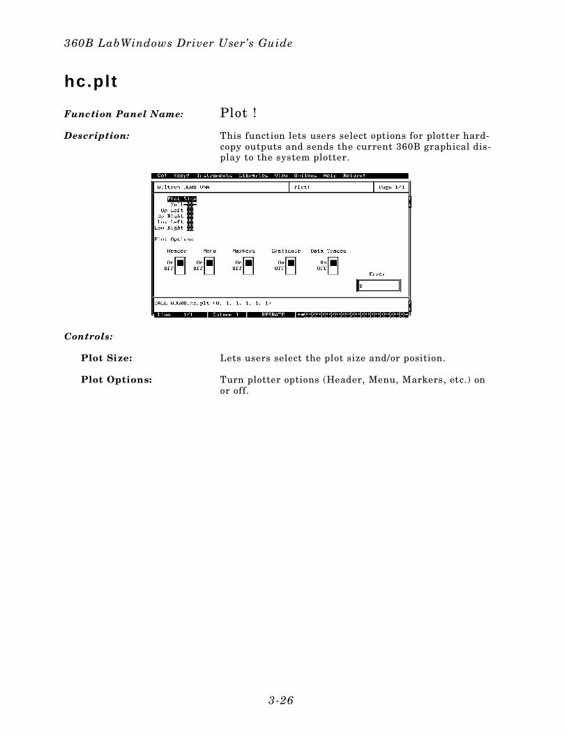
hc.pl t
Function Panel Name: Plot !
Description: This function lets users select options for plotter hard-copy outputs and sends the current 360B graphical dis-play to the system plotter.
Controls:
Plot Size: Lets users select the plot size and/or position.
Plot Options: Turn plotter options (Header, Menu, Markers, etc.) onor off.
360B LabWindows Driver User’s Guide
3-26
Input Parameters: (D) is the default setting.
Var iableName
Var iableType Descript ion Detai ls Range
PLS% Integer Plot s ize 0 = Ful l (D)1 = Upper Left 2 = Upper Right3 = Lower Left 4 = Lower Right
HDR% Integer Header 0 = Off (D)1 = On
MENU% Integer Menu 0 = Off (D) 1 = On
MKR% Integer Markers 0 = Off (D)1 = On
GRAT% Integer Graticule 0 = Off (D) 1 = On
DTR% Integer Data trace 0 = Off (D) 1 = On
Output Parameters: None.
Error: LabWindows error codes(220-300). W360B error codes.
Program Examples:
Quick BASIC:
REM Select p lot ter opt ions.
CALL W360B.hc.plt (PLS%,HDR%,MENU%,MKR%,GRAT%,DTR%)
Microsoft C:
/ * Select plo tter options. */
W360B_hc_pl t (PLS,HDR,MENU,MKR,GRAT,DTR)
Section 3
3-27
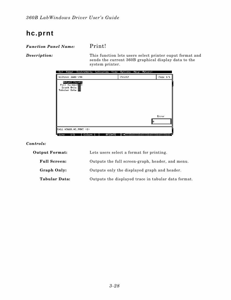
hc.prnt
Function Panel Name: Print!
Description: This function lets users select printer ouput format andsends the current 360B graphical display data to thesystem printer.
Controls:
Output Format: Lets users select a format for printing.
Full Screen: Outputs the full screen-graph, header, and menu.
Graph Only: Outputs only the displayed graph and header.
Tabular Data: Outputs the displayed trace in tabular data format.
360B LabWindows Driver User’s Guide
3-28
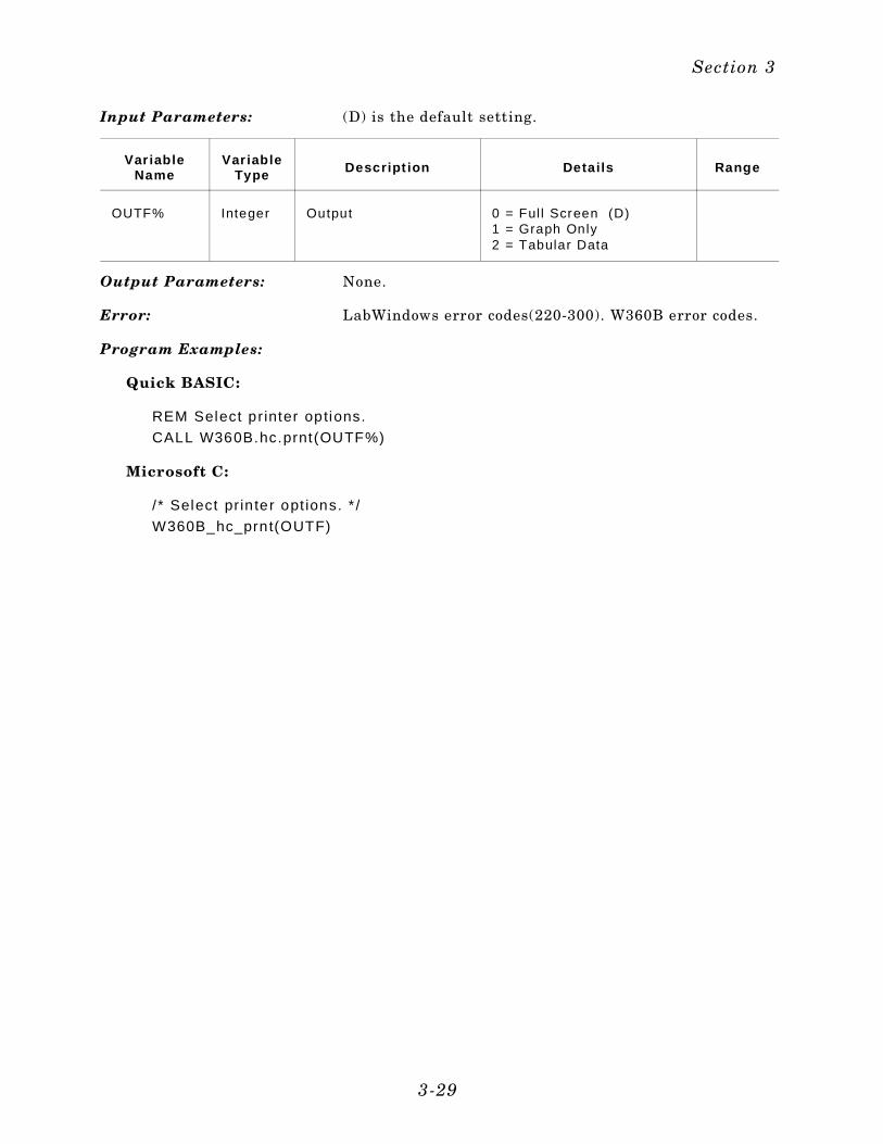
Input Parameters: (D) is the default setting.
Var iableName
Var iableType Descript ion Detai ls Range
OUTF% Integer Output 0 = Ful l Screen (D)1 = Graph Only 2 = Tabular Data
Output Parameters: None.
Error: LabWindows error codes(220-300). W360B error codes.
Program Examples:
Quick BASIC:
REM Select pr inter options.
CALL W360B.hc.prnt(OUTF%)
Microsoft C:
/ * Select pr in ter opt ions. * /
W360B_hc_prnt(OUTF)
Section 3
3-29
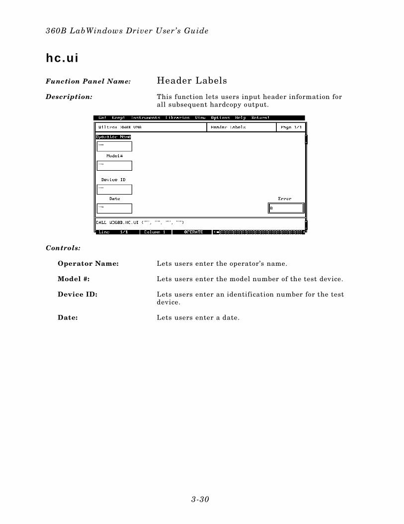
hc.ui
Function Panel Name: Header Labels
Description: This function lets users input header information forall subsequent hardcopy output.
Controls:
Operator Name: Lets users enter the operator’s name.
Model #: Lets users enter the model number of the test device.
Device ID: Lets users enter an identification number for the testdevice.
Date: Lets users enter a date.
360B LabWindows Driver User’s Guide
3-30
Input Parameters: (D) is the default setting.
Var iableName
Var iableType Descript ion Detai ls
OPNAME$ Str ing Operator name 12 Characters, maximum
MNUM$ Str ing Model number 12 Characters, maximum
DID$ Str ing Device ID 12 Characters, maximum
DT$ Str ing Date 12 Characters, maximum
Output Parameters: None.
Error: LabWindows error codes(220-300). W360B error codes.
Program Examples:
Quick BASIC:
REM Assign header informat ion.
CALL W360B.hc.ui(OPNAME$,MNUM$,DID$,DT$)
Microsoft C:
/ * Assign header in formation. */
W360B_hc_ui (OPNAME,MNUM,DID,DT)
Section 3
3-31

in i t
Function Panel Name: Initialize
Description: This function opens the GPIB communication with the360B and sets it to its preset state. The device configura-tion must already be completed. System configuration pa-rameters — such as minimum/maximum frequency,firmware revision, etc., — are returned and displayed.
Controls:
VNA Address: Lets users enter a GPIB address for the 360B. The fac-tory-set default address is 6.
Minimum Frequency: Displays the minimum frequency for a full band sweep.
Maximum Frequency: Displays the maximum frequency for a full band sweep.
Minimum Power: Displays the minimum output power to which the 360Bcan be set.
Maximum Output Power:
Displays the maximum output power to which the 360Bcan be set.
Firmware Rev: Displays the 360B firmware revision level.
360B LabWindows Driver User’s Guide
3-32
Debug Flag:(Secondary Function)
Controls the Debug Function. This function is discussedin Section 2.
Off: Debug Function is off.
On: All appropriate W360B errors will be returned, refer topage 2-8.
Fast Reset:(Secondary Function)
Turns the fast reset mode on or off. When enabled, GPIBcommunication is established, but the 360B is not presetto its default state. In other words, a normal reset is thesame as pressing the 360B front panel DEFAULT PRO-GRAM key. Whereas, a Fast Reset merely places the 360Bin the Remote state; it does not reset any of the frontpanel controls.
VNA Model:(Secondary Function)
Lets users select Model 360 or Model 360B, depending onwhich model they will be using.
Input Parameters: (D) is the default setting.
Var iableName
Var iableType Descript ion Detai ls
ADD% Integer VNA Address. Returns the fo l lowing global variables asstr ings: Minimum Operating Frequency Maximum Operating Frequency Minimum Source Power Maximum Source PowerFirmware Revision
Output Parameters: None.
Error: LabWindows error codes(220-300). W360B error codes.
Program Examples:
QuickBASIC:
REM Assign GPIB address.
i .. ret% = W360B.ini t (ADD%)
Microsoft C:
/ * Assign GPIB address. * /
i_ret = W360B_ini t (ADD)
Section 3
3-33
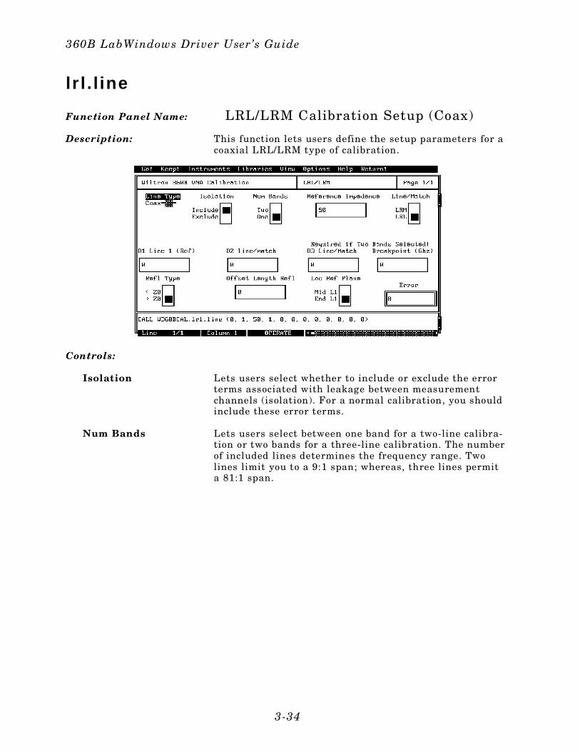
l r l . l ine
Function Panel Name: LRL/LRM Calibration Setup (Coax)
Description: This function lets users define the setup parameters for acoaxial LRL/LRM type of calibration.
Controls:
Isolation Lets users select whether to include or exclude the errorterms associated with leakage between measurementchannels (isolation). For a normal calibration, you shouldinclude these error terms.
Num Bands Lets users select between one band for a two-line calibra-tion or two bands for a three-line calibration. The numberof included lines determines the frequency range. Twolines limit you to a 9:1 span; whereas, three lines permita 81:1 span.
360B LabWindows Driver User’s Guide
3-34
Reference Impedance(360B only)
Lets users enter the system reference impedance (Zo).
Line/Match Lets users select between line-reflect-line (LRL) or line-re-flect-match (LRM) calibration.
D1 Line 1 (Refl) Lets users enter the length of Line 1, for an LRL or LRMcalibration.
D2 L ine/Match Lets users enter the length of Line 2, for an LRL calibra-tion, or is set to zero for a lowband standard for an LRMcalibration.
D3 Line/Match Lets users enter the length of Line 3, for an LRL calibra-tion, or zero for the highband standard for an LRM cali-bration (used only for two-band calibrations).
Breakpoint (GHz) Lets users enter the breakpoint frequency. For two-lineLRL calibration, the breakpoint frequency should equalthe upper frequency of the low-frequency LRL line. For acombined LRL/LRM calibration, breakpoint frequencyshould equal the top calibration frequency divided by six.Example: For a frequency range of 0.04 to 60 GHz, thebreakpoint should equal 10 GHz (60/6). For an LRM cali-bration, there is no breakpoint frequency.
Refl Type: Lets users select between an Open (>Zo) and a Short(<Zo) reflection standard.
Offset Length Refl: Lets users enter an offset-length value (mm) for the reflec-tion standard.
Loc Ref Plane: Lets users select a location for their calibration referenceplanes.
Mid L1 Locates the reference plane at the mid-point of Line 1.
End L1 Locates the reference planes at the ends of Line 1.
Section 3
3-35
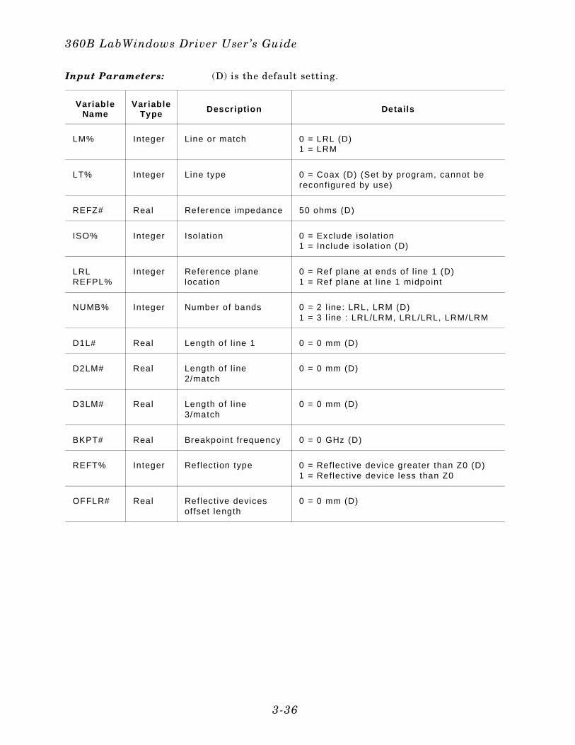
Input Parameters: (D) is the default setting.
VariableName
Var iableType Descr ipt ion Detai ls
LM% Integer Line or match 0 = LRL (D)1 = LRM
LT% Integer Line type 0 = Coax (D) (Set by program, cannot bereconfigured by use)
REFZ# Real Reference impedance 50 ohms (D)
ISO% Integer Isolat ion 0 = Exclude isolat ion1 = Include isolat ion (D)
LRLREFPL%
Integer Reference planelocation
0 = Ref plane at ends of l ine 1 (D) 1 = Ref plane at l ine 1 midpoint
NUMB% Integer Number of bands 0 = 2 l ine: LRL, LRM (D) 1 = 3 l ine : LRL/LRM, LRL/LRL, LRM/LRM
D1L# Real Length of l ine 1 0 = 0 mm (D)
D2LM# Real Length of l ine2/match
0 = 0 mm (D)
D3LM# Real Length of l ine3/match
0 = 0 mm (D)
BKPT# Real Breakpoint frequency 0 = 0 GHz (D)
REFT% Integer Reflect ion type 0 = Reflect ive device greater than Z0 (D) 1 = Reflect ive device less than Z0
OFFLR# Real Reflect ive devicesoffset length
0 = 0 mm (D)
360B LabWindows Driver User’s Guide
3-36
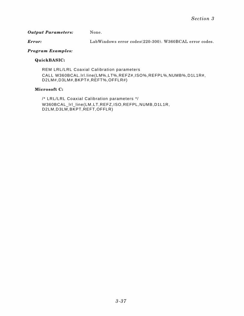
Output Parameters: None.
Error: LabWindows error codes(220-300). W360BCAL error codes.
Program Examples:
QuickBASIC:
REM LRL/LRL Coaxial Cal ibration parameters
CALL W360BCAL. l r l . l ine(LM%,LT%,REFZ#,ISO%,REFPL%,NUMB%,D1L1R#,D2LM#,D3LM#,BKPT#,REFT%,OFFLR#)
Microsoft C:
/ * LRL/LRL Coaxia l Cal ibrat ion parameters */
W360BCAL_l r l_l ine(LM,LT,REFZ,ISO,REFPL,NUMB,D1L1R,D2LM,D3LM,BKPT,REFT,OFFLR)
Section 3
3-37
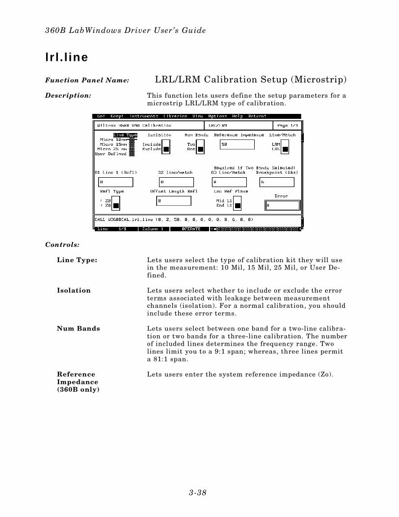
l r l . l ine
Function Panel Name: LRL/LRM Calibration Setup (Microstrip)
Description: This function lets users define the setup parameters for amicrostrip LRL/LRM type of calibration.
Controls:
Line Type: Lets users select the type of calibration kit they will usein the measurement: 10 Mil, 15 Mil, 25 Mil, or User De-fined.
Isolation Lets users select whether to include or exclude the errorterms associated with leakage between measurementchannels (isolation). For a normal calibration, you shouldinclude these error terms.
Num Bands Lets users select between one band for a two-line calibra-tion or two bands for a three-line calibration. The numberof included lines determines the frequency range. Twolines limit you to a 9:1 span; whereas, three lines permita 81:1 span.
Reference Impedance(360B only)
Lets users enter the system reference impedance (Zo).
360B LabWindows Driver User’s Guide
3-38
Line/Match Lets users select between line-reflect-line (LRL) or line-re-flect-match (LRM) calibration.
D1 Line 1 (Refl) Lets users enter the length of Line 1, for an LRL or LRMcalibration.
D2 L ine/Match Lets users enter the length of Line 2, for an LRL calibra-tion, or is set to zero for the lowband standard for anLRM calibration.
D3 Line/Match Lets users enter the length of Line 3, for an LRL calibra-tion, or zero for the highband standard for an LRM cali-bration (used only for two-band calibrations).
Breakpoint (GHz) Lets users enter the breakpoint frequency. For two-lineLRL calibration, the breakpoint frequency should equalthe upper frequency of the low-frequency LRL line. For acombined LRL/LRM calibration, breakpoint frequencyshould equal the top calibration frequency divided by six.Example: For a frequency range of 0.04 to 60 GHz, thebreakpoint should equal 10 GHz (60/6).
Refl Type: Lets users select between an Open (>Zo) and a Short(<Zo) reflection standard.
Offset Length Refl: Lets users enter an offset-length value (mm) for the reflec-tion standard.
Loc Ref Plane: Lets users select a location for their calibration referenceplanes.
Mid L1 Locates the reference plane at the mid-point of Line 1.
End L1 Locates the reference planes at the ends of Line 1.
Section 3
3-39
Input Parameters: (D) is the default setting.
VariableName
Var iableType Descr ipt ion Detai ls
LM% Integer Line or match 0 = LRL (D)
LT% Integer Line type 1 = Micro 10 mm (D)2 = Micro 15 mm 3 = Micro 25 mm 4 = User Defined
REFZ# Real Reference impedance 50 ohms (D)
ISO% Integer Isolat ion 0 = Exclude isolat ion1 = Include isolat ion (D)
LRLREFPL%
Integer Reference planelocation
0 = Ref plane at ends of l ine 1 (D) 1 = Ref plane at l ine 1 midpoint
NUMB% Integer Number of bands 0 = 2 l ine: LRL/LRM (D) 1 = 3 l ine : LRL/LRM, LRL/LRL, LRM/LRM
D1L# Real Length of l ine 1 0 = 0 mm (D)
D2LM# Real Length of l ine2/match
0 = 0 mm (D)
D3LM# Real Length of l ine3/match
0 = 0 mm (D)
BKPT# Real Breakpoint frequency 0 = 0 GHz (D)
REFT% Integer Reflect ion type 0 = Reflect ive device greater than Z0 (D) 1 = Reflect ive device less than Z0
OFFLR# Real Reflect ive devicesoffset length
0 = 0 mm (D)
360B LabWindows Driver User’s Guide
3-40
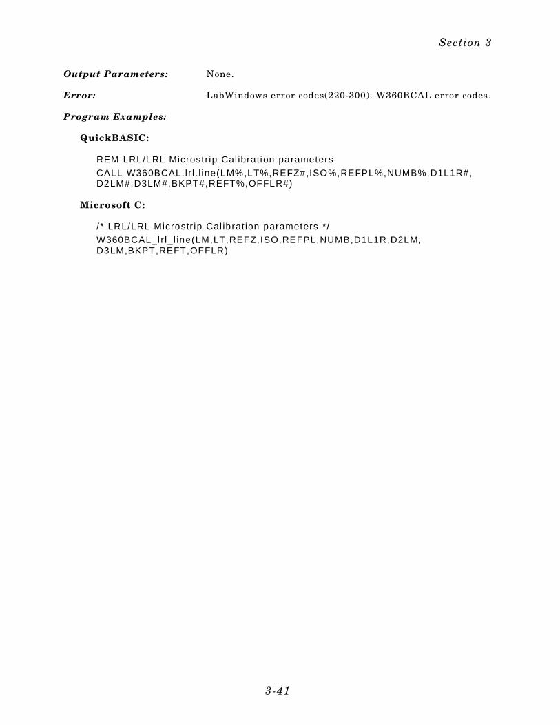
Output Parameters: None.
Error: LabWindows error codes(220-300). W360BCAL error codes.
Program Examples:
QuickBASIC:
REM LRL/LRL Microstr ip Cal ibration parameters
CALL W360BCAL. l r l . l ine(LM%,LT%,REFZ#,ISO%,REFPL%,NUMB%,D1L1R#,D2LM#,D3LM#,BKPT#,REFT%,OFFLR#)
Microsoft C:
/ * LRL/LRL Microstr ip Cal ibrat ion parameters */
W360BCAL_l r l_l ine(LM,LT,REFZ,ISO,REFPL,NUMB,D1L1R,D2LM,D3LM,BKPT,REFT,OFFLR)
Section 3
3-41

l r l . l ine
Function Panel Name: LRL/LRM Calibration Setup (Waveguide)
Description: This function lets users define the setup parameters for awaveguide LRL/LRM type of calibration.
Controls:
Isolation Lets users select whether to include or exclude the errorterms associated with leakage between measurementchannels (isolation). For a normal calibration, you shouldinclude these error terms.
Num Bands Lets users select between one band for a two-line calibra-tion or two bands for a three-line calibration. The numberof included lines determines the frequency range. Twolines limit you to a 9:1 span; whereas, three lines permita 81:1 span.
360B LabWindows Driver User’s Guide
3-42
Reference Impedance(360B only)
Lets users enter the system reference impedance (Zo).
Line/Match Lets users select between line-reflect-line (LRL) or line-re-flect-match (LRM) calibration.
D1 Line 1 (Refl) Lets users enter the length of Line 1, for an LRL or LRMcalibration.
D2 L ine/Match Lets users enter the length of Line 2, for an LRL calibra-tion, or is set to zero for the lowband standard for anLRM calibration.
D3 Line/Match Lets users enter the length of Line 3, for an LRL calibra-tion, or zero for the value of the highband standard for anLRM calibration (used only for two-band calibrations).
Breakpoint (GHz) Lets users enter the breakpoint frequency. For two-lineLRL calibration, the breakpoint frequency should equalthe upper frequency of the low-frequency LRL line. For acombined LRL/LRM calibration, breakpoint frequencyshould equal the top calibration frequency divided by six.Example: For a frequency range of 0.04 to 60 GHz, thebreakpoint should equal 10 GHz (60/6).
Refl Type: Lets users select between an Open (>Zo) and a Short(<Zo) reflection standard.
Offset Length Refl: Lets users enter an offset-length value (mm) for the reflec-tion standard.
Loc Ref Plane: Lets users select a location for their calibration referenceplanes.
Mid L1 Locates the reference plane at the mid-point of Line 1.
End L1 Locates the reference planes at the ends of Line 1.
Section 3
3-43
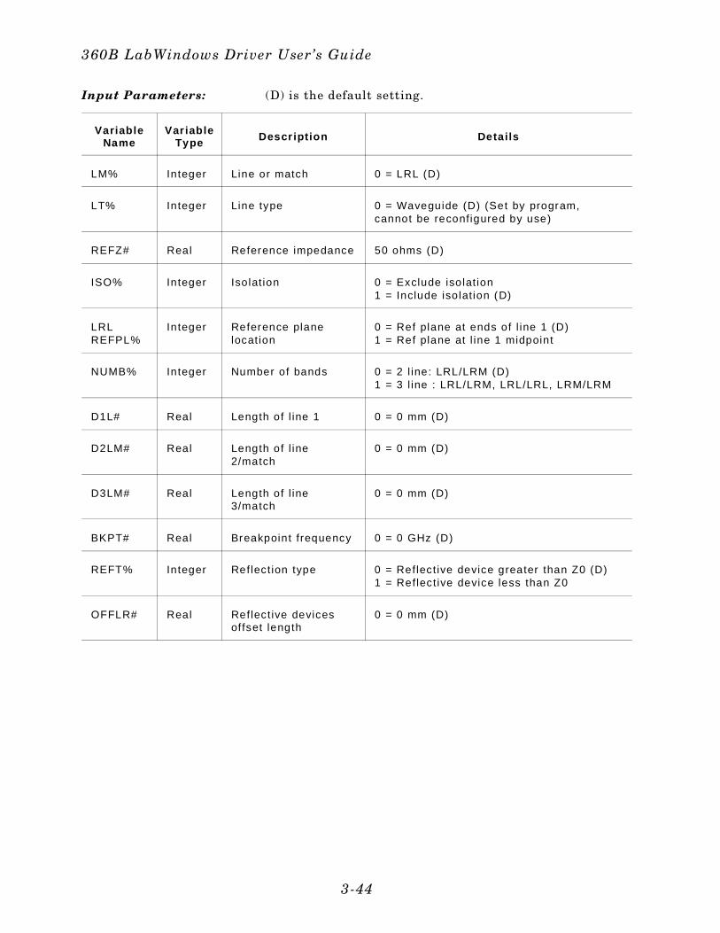
Input Parameters: (D) is the default setting.
VariableName
Var iableType Descr ipt ion Detai ls
LM% Integer Line or match 0 = LRL (D)
LT% Integer Line type 0 = Waveguide (D) (Set by program,cannot be reconfigured by use)
REFZ# Real Reference impedance 50 ohms (D)
ISO% Integer Isolat ion 0 = Exclude isolat ion1 = Include isolat ion (D)
LRLREFPL%
Integer Reference planelocation
0 = Ref plane at ends of l ine 1 (D) 1 = Ref plane at l ine 1 midpoint
NUMB% Integer Number of bands 0 = 2 l ine: LRL/LRM (D) 1 = 3 l ine : LRL/LRM, LRL/LRL, LRM/LRM
D1L# Real Length of l ine 1 0 = 0 mm (D)
D2LM# Real Length of l ine2/match
0 = 0 mm (D)
D3LM# Real Length of l ine3/match
0 = 0 mm (D)
BKPT# Real Breakpoint frequency 0 = 0 GHz (D)
REFT% Integer Reflect ion type 0 = Reflect ive device greater than Z0 (D) 1 = Reflect ive device less than Z0
OFFLR# Real Reflect ive devicesoffset length
0 = 0 mm (D)
360B LabWindows Driver User’s Guide
3-44
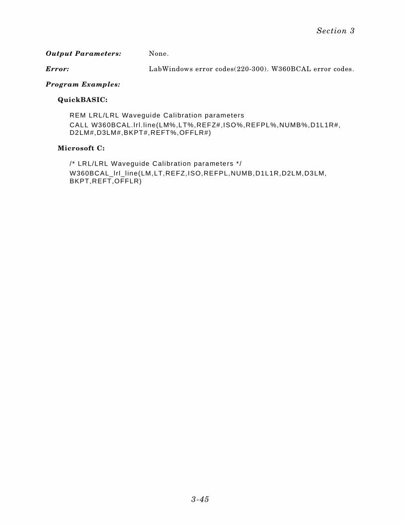
Output Parameters: None.
Error: LabWindows error codes(220-300). W360BCAL error codes.
Program Examples:
QuickBASIC:
REM LRL/LRL Waveguide Calibrat ion parameters
CALL W360BCAL. l r l . l ine(LM%,LT%,REFZ#,ISO%,REFPL%,NUMB%,D1L1R#,D2LM#,D3LM#,BKPT#,REFT%,OFFLR#)
Microsoft C:
/ * LRL/LRL Waveguide Calibrat ion parameters * /
W360BCAL_l r l_l ine(LM,LT,REFZ,ISO,REFPL,NUMB,D1L1R,D2LM,D3LM,BKPT,REFT,OFFLR)
Section 3
3-45
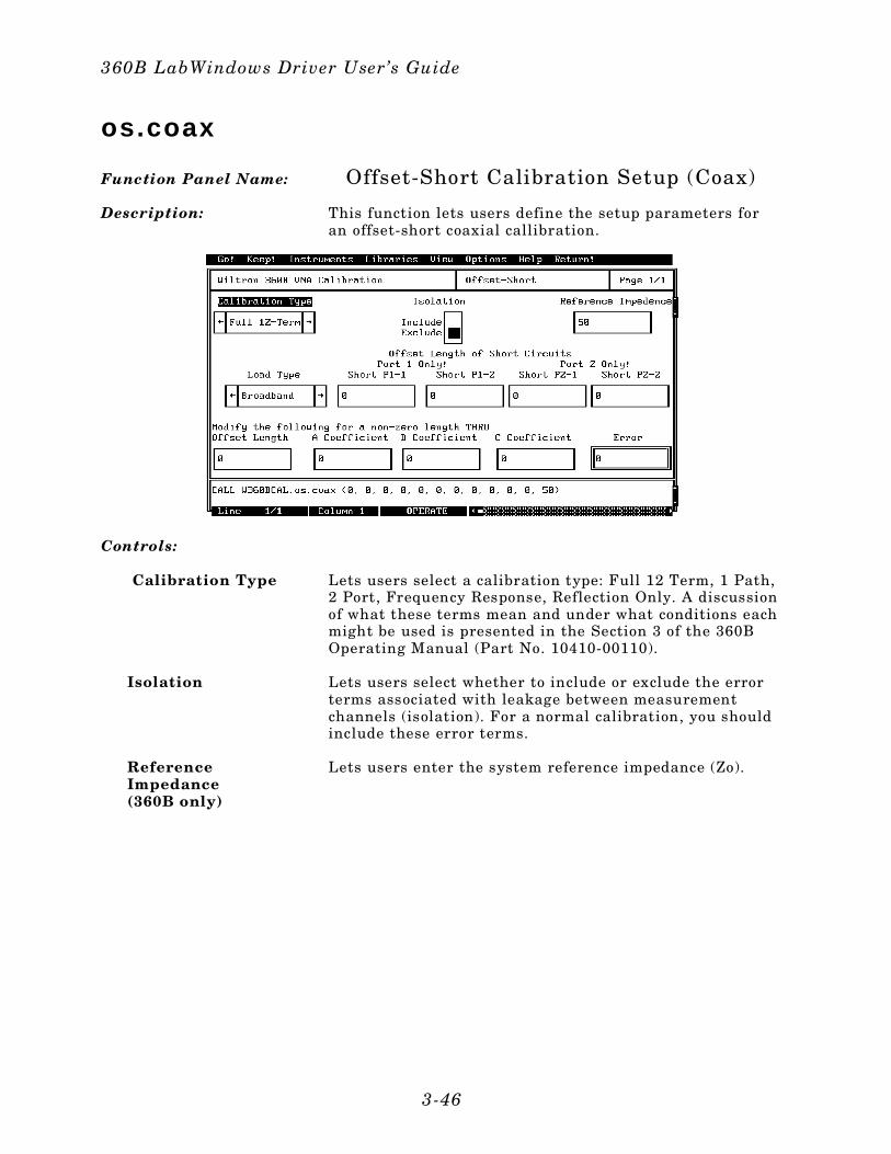
os.coax
Function Panel Name: Offset-Short Calibration Setup (Coax)
Description: This function lets users define the setup parameters foran offset-short coaxial callibration.
Controls:
Calibration Type Lets users select a calibration type: Full 12 Term, 1 Path,2 Port, Frequency Response, Reflection Only. A discussionof what these terms mean and under what conditions eachmight be used is presented in the Section 3 of the 360BOperating Manual (Part No. 10410-00110).
Isolation Lets users select whether to include or exclude the errorterms associated with leakage between measurementchannels (isolation). For a normal calibration, you shouldinclude these error terms.
Reference Impedance(360B only)
Lets users enter the system reference impedance (Zo).
360B LabWindows Driver User’s Guide
3-46

Load Type Lets users select between two load types: broadband orsliding. If the measurement requires the highest degreeof precision, the user should choose “Sliding”; otherwisethe user should chose “Broadband.” Refer to the 360B Net-work Analyzer Getting Started manual (Part No. 11410-00111) for a discussion of load types, and to the 360BOperating Manual, Section 8, for a procedure on usingsliding loads.
Short P1-1 Lets users enter the length that the Short device #1 is off-set from the Port 1 reference plane.
Short P1-2 Lets users enter the length that the Short device #2 is off-set from the Port 1 reference plane.
Short P2-1 Lets users enter the length that the Short device #1 is off-set from the Port 2 reference plane.
Short P2-2 Lets users enter the length that the Short device #2 is off-set from the Port 2 reference plane.
Offset Length Lets users enter the length of a non-zero-length throughline, if necessary. The throughline loss equation is de-fined by a dc coefficient (A), a frequency coefficient (B),and a frequency exponent (C). The equation:
Loss (dB/m) = A + B x (Frequency)C
A Coefficient Lets users enter a value for the dc coefficient (see above).
B Coefficient Lets users enter a value for the frequency coefficient (seeabove).
C Coefficient Lets users enter a value for the frequency exponent (seeabove).
Section 3
3-47
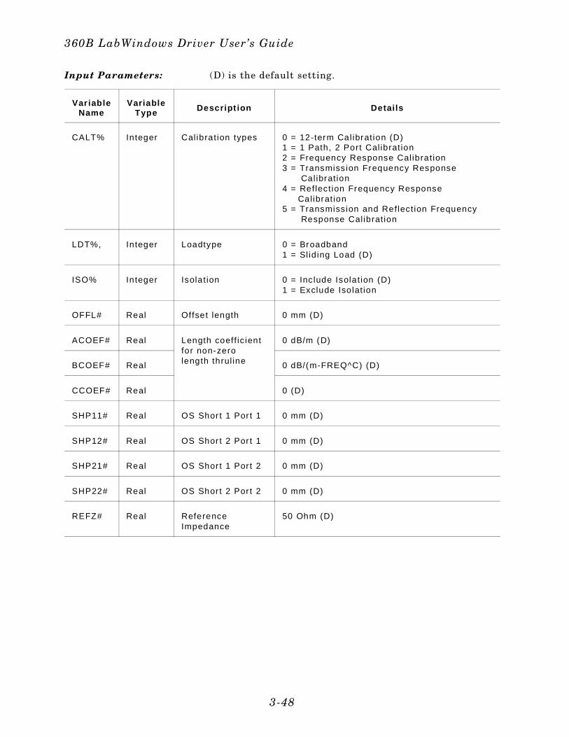
Input Parameters: (D) is the default setting.
Var iableName
VariableType Descript ion Detai ls
CALT% Integer Cal ibrat ion types 0 = 12-term Cal ibrat ion (D) 1 = 1 Path, 2 Port Cal ibrat ion 2 = Frequency Response Cal ibrat ion 3 = Transmission Frequency Response Cal ibrat ion 4 = Reflect ion Frequency Response Cal ibrat ion 5 = Transmission and Reflect ion Frequency Response Calibrat ion
LDT%, Integer Loadtype 0 = Broadband 1 = Sl id ing Load (D)
ISO% Integer Isolat ion 0 = Inc lude Isolat ion (D) 1 = Exclude Isolat ion
OFFL# Real Offset length 0 mm (D)
ACOEF# Real Length coeff ic ientfor non-zerolength thrul ine
0 dB/m (D)
BCOEF# Real 0 dB/(m-FREQ^C) (D)
CCOEF# Real 0 (D)
SHP11# Real OS Shor t 1 Por t 1 0 mm (D)
SHP12# Real OS Shor t 2 Por t 1 0 mm (D)
SHP21# Real OS Shor t 1 Por t 2 0 mm (D)
SHP22# Real OS Shor t 2 Por t 2 0 mm (D)
REFZ# Real Reference Impedance
50 Ohm (D)
360B LabWindows Driver User’s Guide
3-48
Output Parameters: None.
Error: LabWindows error codes(220-300). W360BCAL error codes.
Program Examples:
QuickBASIC:
REM Offset-Short coaxial ca l ibrat ion parameters
CALL W360BCAL.os.coax(CALT%,LDT%,ISO%,OFFL#,ACOEF#,BCOEF#,CCOEF#,SHP11#,SHP12#,SHP21#,SHP22#,REFZ#)
Microsoft C:
/ * Offset-Short coaxial cal ibrat ion parameters * /
W360BCAL_os_coax(CALT,LDT,ISO,OFFL,ACOEF,BCOEF,CCOEF,SHP11,SHP12,SHP21,SHP22,REFZ)
Section 3
3-49
os.micro
Function Panel Name: Offset-Short Calibration Setup (Microstrip)
Description: This function lets users define the setup parameters foran offset-short calibration in microstrip.
Controls:
Calibration Type Lets users select a calibration type: Full 12 Term, 1 Path,2 Port, Frequency Response, Reflection Only. A discussionof what these terms mean and under what conditions eachmight be used is presented in the Section 3 of the 360BOperating Manual (Part No. 10410-00110).
Isolation Lets users select whether to include or exclude the errorterms associated with leakage between measurementchannels (isolation). For a normal calibration, you shouldinclude these error terms.
Calibration Kit Lets users select the type of calibration kit they will usein the measurement: 10 Mil, 15 Mil, 25 Mil, or User De-fined.
360B LabWindows Driver User’s Guide
3-50
Short P1-1 Lets users enter the length that the Short device #1 is off-set from the Port 1 reference plane.
Short P1-2 Lets users enter the length that the Short device #2 is off-set from the Port 1 reference plane.
Short P2-1 Lets users enter the length that the Short device #1 is off-set from the Port 2 reference plane.
Short P2-2 Lets users enter the length that the Short device #2 is off-set from the Port 2 reference plane.
Offset Length Lets users enter the length of a non-zero-length throughline, if necessary.The throughline loss equation is definedby a dc coefficient (A), a frequency coefficient (B), and afrequency exponent (C). The equation:
Loss (dB/m) = A + B x (Frequency)C
A Coefficient Lets users enter a value for the dc coefficient (see above).
B Coefficient Lets users enter a value for the frequency coefficient (seeabove).
C Coefficient Lets users enter a value for the frequency exponent (seeabove).
Section 3
3-51
Input Parameters: (D) is the default setting.
Var iableName
VariableType Descript ion Detai ls
CALT% Integer Cal ibrat ion types 0 = 12-term Cal ibrat ion (D) 1 = 1 Path, 2 Port Cal ibrat ion 2 = Frequency Response Cal ibrat ion 3 = Transmission Frequency Response Calibrat ion 4 = Reflect ion Frequency Response Calibrat ion 5 = Transmission and Reflect ion Frequency Response Calibrat ion
ISO% Integer Isolat ion 0 = Inc lude Isolat ion (D) 1 = Exclude Isolat ion
CLKIT% Integer Cal ibration Kit 0 = 10mm (D) 1 = 15mm 2 = 25mm 3 = User Defined
OFFL# Real Offset length 0mm (D)
ACOEF# Real Length coeff ic ientfor non-zerolength thrul ine
0 dB/m (D)
BCOEF# Real 0 dB/(m-FREQ^C) (D)
CCOEF# Real 0 (D)
SHP11# Real OS Shor t 1 Por t 1 0mm (D)
SHP12# Real OS Shor t 2 Por t 1 0mm (D)
SHP21# Real OS Shor t 1 Por t 2 0mm (D)
SHP22# Real OS Shor t 2 Por t 2 0mm (D)
360B LabWindows Driver User’s Guide
3-52
Output Parameters: None.
Error: LabWindows error codes(220-300). W360BCAL error codes.
Program Examples:
QuickBASIC:
REM Offset-Short microstr ip cal ibrat ion parameters
CALL W360BCAL.os.micro(CALT%,ISO%,CLKIT%,OFFL#,ACOEF#,BCOEF#,CCOEF#,SHP11#,SHP12#,SHP21#,SHP22#)
Microsoft C:
/ * Offset-Short microstr ip cal ibration parameters */
W360BCAL_os_micro(CALT,ISO,CLKIT,OFFL,ACOEF,BCOEF,CCOEF,SHP11,SHP12,SHP21,SHP22)
Section 3
3-53
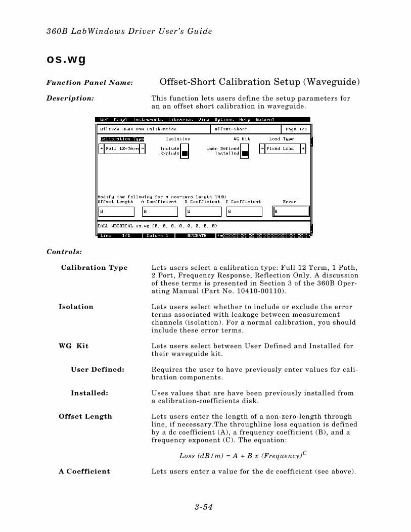
os.wg
Function Panel Name: Offset-Short Calibration Setup (Waveguide)
Description: This function lets users define the setup parameters foran an offset short calibration in waveguide.
Controls:
Calibration Type Lets users select a calibration type: Full 12 Term, 1 Path,2 Port, Frequency Response, Reflection Only. A discussionof these terms is presented in Section 3 of the 360B Oper-ating Manual (Part No. 10410-00110).
Isolation Lets users select whether to include or exclude the errorterms associated with leakage between measurementchannels (isolation). For a normal calibration, you shouldinclude these error terms.
WG Kit Lets users select between User Defined and Installed fortheir waveguide kit.
User Defined: Requires the user to have previously enter values for cali-bration components.
Installed: Uses values that are have been previously installed froma calibration-coefficients disk.
Offset Length Lets users enter the length of a non-zero-length throughline, if necessary.The throughline loss equation is definedby a dc coefficient (A), a frequency coefficient (B), and afrequency exponent (C). The equation:
Loss (dB/m) = A + B x (Frequency)C
A Coefficient Lets users enter a value for the dc coefficient (see above).
360B LabWindows Driver User’s Guide
3-54
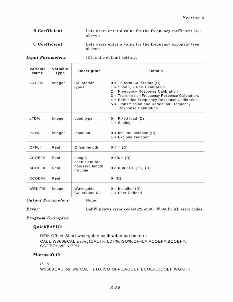
B Coefficient Lets users enter a value for the frequency coefficient (seeabove).
C Coefficient Lets users enter a value for the frequency exponent (seeabove).
Input Parameters: (D) is the default setting.
Var iableName
Var iableType Descript ion Detai ls
CALT% Integer Cal ibrat iontypes
0 = 12-term Cal ibration (D) 1 = 1 Path, 2 Port Cal ibrat ion 2 = Frequency Response Cal ibrat ion 3 = Transmission Frequency Response Calibrat ion. 4 = Reflect ion Frequency Response Cal ibrat ion 5 = Transmission and Reflect ion Frequency Response Calibrat ion
LTD% Integer Load type 0 = Fixed load (D)1 = Sl id ing
ISO% Integer Isolat ion 0 = Inc lude Isolat ion (D) 1 = Exclude Isolat ion
OFFL# Real Offset length 0 mm (D)
ACOEF# Real Lengthcoeff icient fornon-zero lengththrul ine
0 dB/m (D)
BCOEF# Real 0 dB/(m-FREQ^C) (D)
CCOEF# Real 0 (D)
WGKIT% Integer WaveguideCalibrat ion Kit
0 = Instal led (D)1 = User Defined
Output Parameters: None.
Error: LabWindows error codes(220-300). W360BCAL error codes.
Program Examples:
QuickBASIC:
REM Offset-Short waveguide cal ibration parameters
CALL W360BCAL.os.wg(CALT%,LDT%,ISO%,OFFL#,ACOEF#,BCOEF#,CCOEF#,WGKIT%)
Microsoft C:
/ * */
W360BCAL_os_wg(CALT,LTD,ISO,OFFL,ACOEF,BCOEF,CCOEF,WGKIT)
Section 3
3-55
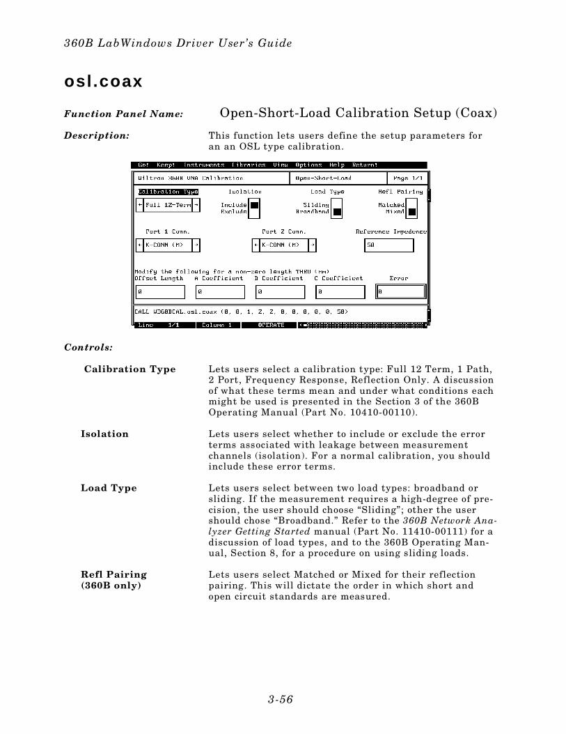
osl.coax
Function Panel Name: Open-Short-Load Calibration Setup (Coax)
Description: This function lets users define the setup parameters foran an OSL type calibration.
Controls:
Calibration Type Lets users select a calibration type: Full 12 Term, 1 Path,2 Port, Frequency Response, Reflection Only. A discussionof what these terms mean and under what conditions eachmight be used is presented in the Section 3 of the 360BOperating Manual (Part No. 10410-00110).
Isolation Lets users select whether to include or exclude the errorterms associated with leakage between measurementchannels (isolation). For a normal calibration, you shouldinclude these error terms.
Load Type Lets users select between two load types: broadband orsliding. If the measurement requires a high-degree of pre-cision, the user should choose “Sliding”; other the usershould chose “Broadband.” Refer to the 360B Network Ana-lyzer Getting Started manual (Part No. 11410-00111) for adiscussion of load types, and to the 360B Operating Man-ual, Section 8, for a procedure on using sliding loads.
Refl Pairing(360B only)
Lets users select Matched or Mixed for their reflectionpairing. This will dictate the order in which short andopen circuit standards are measured.
360B LabWindows Driver User’s Guide
3-56
Matched Provides for calibrating using first an Open on both portsthen a Short on both ports.
Mixed Provides for calibrating using first an Open on one portand a Short on the other, then a Short on one port and aOpen on the other.
Port 1 Conn Lets users choose the type of connector used for Test Port1: SMA(M), SMA(F), K-CONN (F), K-CONN(M), TYPE-N(M), TYPE N (F), GPC-3.5 (M), GPC 3.5 (F), GPC-7, orUser Defined.
NOTEPrior to selecting the User-Defined connector(above), users must define the open and short pa-rameter from the udef.coax function panel. Inother words, the udef.coax routine must be exe-cuted before the osl.coax routine.
Port 2 Conn Lets users choose the type of connector used for Test Port2: SMA(M), SMA(F), K-CONN (F), K-CONN(M), TYPE-N(M), TYPE N (F), GPC-3.5 (M), GPC 3.5 (F), GPC-7, orUser Defined. See above note.
Reference Impedance(360B only)
Lets users enter the system reference impedance (Zo).
Offset Length Lets users enter the length of a non-zero-length throughline, if necessary. The throughline loss equation is de-fined by a dc coefficient (A), a frequency coefficient (B),and a frequency exponent (C). The equation:
Loss (dB/m) = A + B x (Frequency)C
A Coefficient Lets users enter a value for the dc coefficient (see above).
B Coefficient Lets users enter a value for the frequency coefficient (seeabove).
C Coefficient Lets users enter a value for the frequency exponent (seeabove).
Section 3
3-57
Input Parameters: (D) is the default setting.
VariableName
VariableType Descript ion Detai ls
CALT% Integer Cal ibrat ion types 0 = 12- term Cal ibrat ion (D) 1 = 1 Path, 2 Por t Cal ibrat ion 2 = Frequency Response Cal ibrat ion 3 = Transmission Frequency Response Calibrat ion 4 = Reflect ion Frequency Response Calibrat ion 5 = Transmission and Reflect ion Frequency Response Calibrat ion
LTD% Integer Load type 0 = Broadband (D)1 = Sl id ing
ISO% Integer Isolat ion 0 = Exclude1 = Include (D)
P1CON% Integer P1 connectortype
0 = SMA (M)1 = SMA (F)2 = K CONN (M) (D)3 = K CONN (F)4 = TYPE N (M)5 = TYPE N (F)6 = GPB – 3.5 (M)7 = GPB – 3.5 (F)8 = GPB 79 = V CONN (M)10 = V CONN (F)11 = TNC (M)12 = TNC (F)13 = 2.4 mm (M)14 = 2.4 mm (F)15 = User Defined (See NOTE on previous page.)
P2CON% Integer P2 connectortype
OFFL# Real Offset length ofTHRU
ACOEF# Real Loss coeff icient 0 dB/m (D)
BCOEF# Real 0 dB/(m-FREQ^C) (D)
CCOEF# Real 0 (D)
REFP% Integer Reflect ionpair ing
0 = Mix (D) 1 = Matched
REFZ# Real Referenceimpedeance
50 ohms (D)
360B LabWindows Driver User’s Guide
3-58

Output Parameters: None.
Error: LabWindows error codes(220-300). W360BCAL error codes.
Program Examples:
QuickBASIC:
REM Offset-Short-Load coaxial ca l ibrat ion parameters
CALL W360BCAL.osl .coax(CALT%,LDT%,ISO%,P1CON%,P2CON%,OFFL#,ACOEF#,BCOEF#,CCOEF#,REFP%,REFZ#)
Microsoft C:
/ * Offset-Short-Load coaxial cal ibrat ion parameters * /
W360BCAL_osl_coax((CALT,LDT,ISO,P1CON,P2CON,OFFL,ACOEF,BCOEF,CCOEF,REFP,REFZ)
Section 3
3-59
osl.micro
Function Panel Name: Open-Short-Load Calibration Setup (Microstrip)
Description: This function users define the setup parameters for an anOSL calibration in microstrip.
Controls:
Calibration Type Lets users select a calibration type: Full 12 Term, 1 Path,2 Port, Frequency Response, Reflection Only. A discussionof what these terms mean and under what conditions eachmight be used is presented in the Section 3 of the 360BOperating Manual (Part No. 10410-00110).
Isolation Lets users select whether to include or exclude the errorterms associated with leakage between measurementchannels (isolation). For a normal calibration, you shouldinclude these error terms.
Refl Pairing(360B only)
Lets users select Matched or Mixed for their reflectionpairing. This will dictate the order in which short andopen circuit standards are measured.
360B LabWindows Driver User’s Guide
3-60
Matched Provides for calibrating using first an Open on both portsthen a Short on both ports.
Mixed Provides for calibrating using first an Open on one portand a Short on the other, then a Short on one port and aOpen on the other.
Calibration Kit Lets users select the type of calibration kit they will usein the measurement: 10 Mil, 15 Mil, 25 Mil, or User De-fined.
NOTEPrior to selecting the User-Defined connector(above), users must define the open and short pa-rameter from the udef.micro function panel. Inother words, the udef.micro routine must be exe-cuted before the osl.micro routine.
Offset Length Lets users enter the length of a non-zero-length throughline, if necessary.The throughline loss equation is definedby a dc coefficient (A), a frequency coefficient (B), and afrequency exponent (C). The equation:
Loss (dB/m) = A + B x (Frequency)C
A Coefficient Lets users enter a value for the dc coefficient (see above).
B Coefficient Lets users enter a value for the frequency coefficient (seeabove).
C Coefficient Lets users enter a value for the frequency exponent (seeabove).
Section 3
3-61
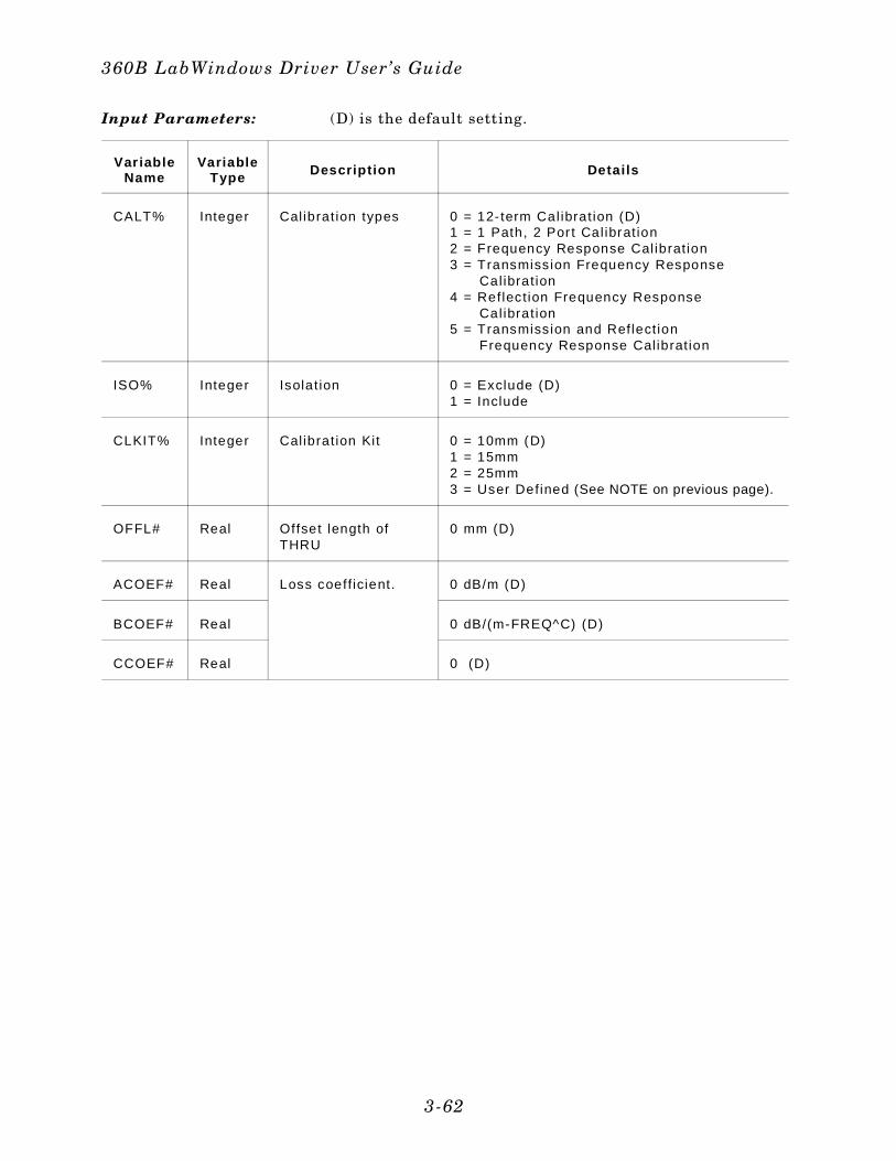
Input Parameters: (D) is the default setting.
Var iableName
VariableType Descript ion Detai ls
CALT% Integer Cal ibrat ion types 0 = 12- term Cal ibrat ion (D) 1 = 1 Path, 2 Por t Cal ibrat ion 2 = Frequency Response Cal ibrat ion 3 = Transmission Frequency Response Cal ibrat ion 4 = Reflect ion Frequency Response Cal ibrat ion 5 = Transmission and Reflect ion Frequency Response Calibrat ion
ISO% Integer Isolat ion 0 = Exclude (D)1 = Include
CLKIT% Integer Calibrat ion Kit 0 = 10mm (D) 1 = 15mm 2 = 25mm3 = User Defined (See NOTE on previous page).
OFFL# Real Offset length ofTHRU
0 mm (D)
ACOEF# Real Loss coeff icient. 0 dB/m (D)
BCOEF# Real 0 dB/(m-FREQ^C) (D)
CCOEF# Real 0 (D)
360B LabWindows Driver User’s Guide
3-62
Output Parameters: None.
Error: LabWindows error codes(220-300). W360BCAL error codes.
Program Examples:
QuickBASIC:
REM Offset-Short-Load microstr ip cal ibrat ion parameters
CALL W360BCAL.osl .mi ro(CALT%,ISO%,CLKIT%,OFFL#,ACOEF#,BCOEF#,CCOEF#,REFP%)
Microsoft C:
/ * Offset-Short-Load microstr ip cal ibration parameters */
W360BCAL_osl_micro(CALT,ISO,CLKIT,OFFL,ACOEF,BCOEF,CCOEF,REFP)
Section 3
3-63
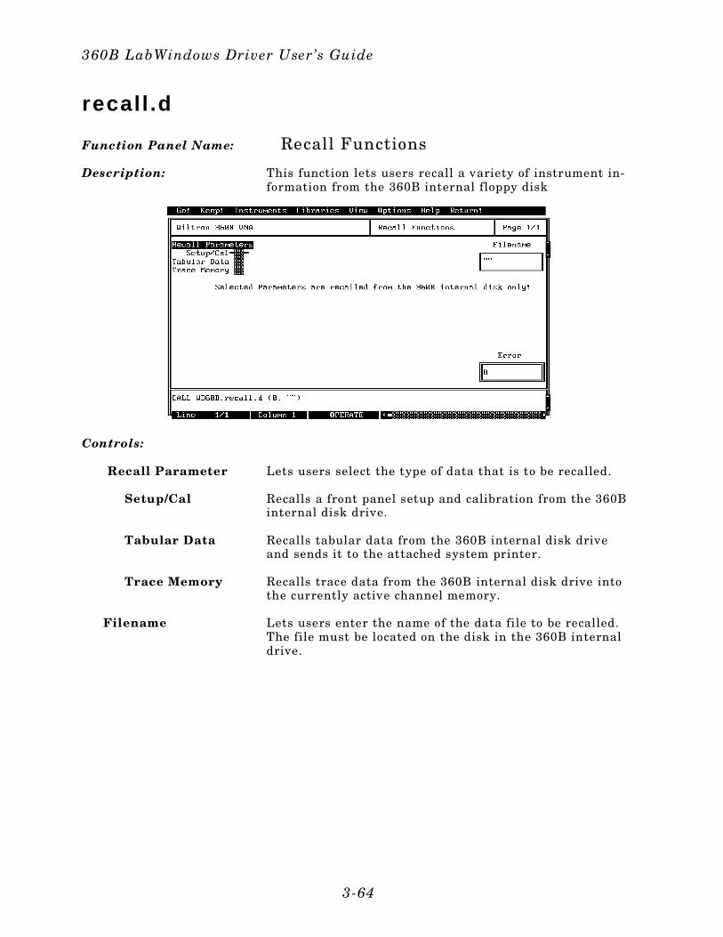
recal l .d
Function Panel Name: Recall Functions
Description: This function lets users recall a variety of instrument in-formation from the 360B internal floppy disk
Controls:
Recall Parameter Lets users select the type of data that is to be recalled.
Setup/Cal Recalls a front panel setup and calibration from the 360Binternal disk drive.
Tabular Data Recalls tabular data from the 360B internal disk driveand sends it to the attached system printer.
Trace Memory Recalls trace data from the 360B internal disk drive intothe currently active channel memory.
Filename Lets users enter the name of the data file to be recalled.The file must be located on the disk in the 360B internaldrive.
360B LabWindows Driver User’s Guide
3-64
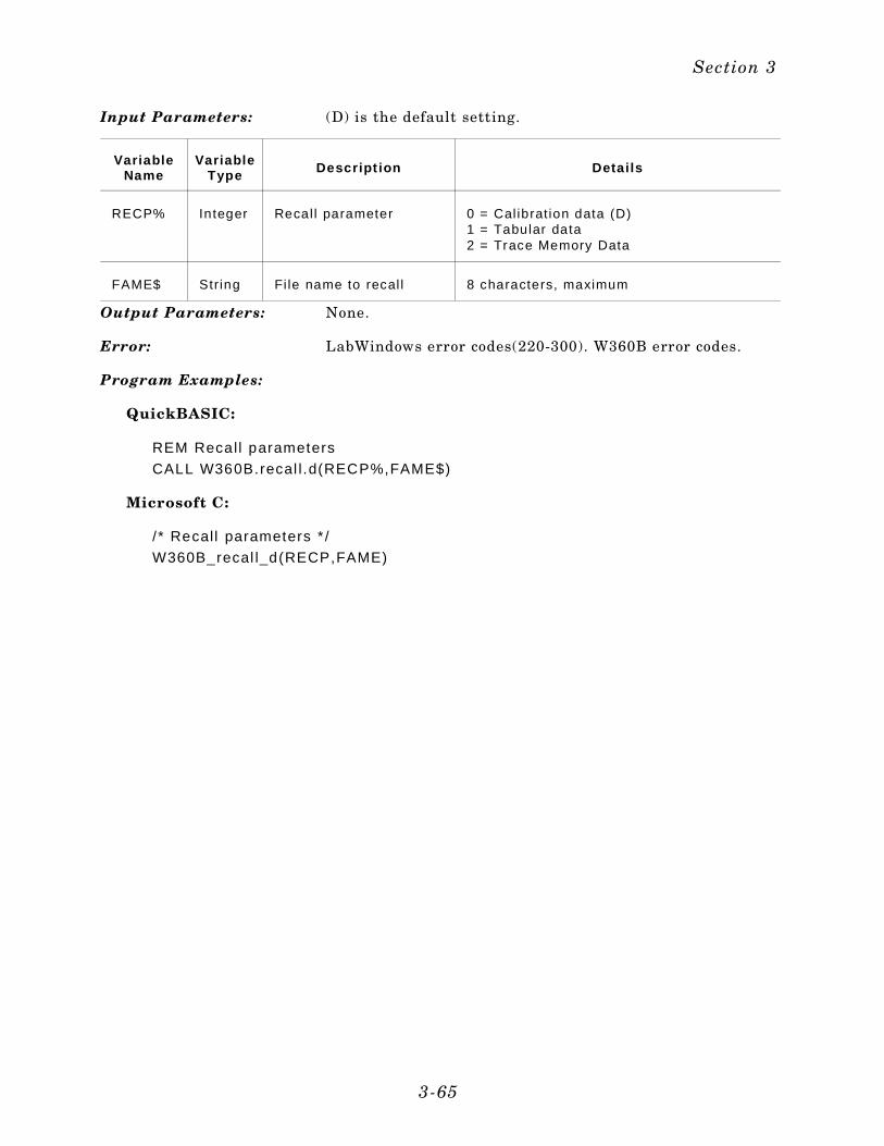
Input Parameters: (D) is the default setting.
VariableName
VariableType Descript ion Detai ls
RECP% Integer Recal l parameter 0 = Cal ibrat ion data (D) 1 = Tabular data 2 = Trace Memory Data
FAME$ String Fi le name to recal l 8 characters, maximum
Output Parameters: None.
Error: LabWindows error codes(220-300). W360B error codes.
Program Examples:
QuickBASIC:
REM Recall parameters
CALL W360B.recal l .d(RECP%,FAME$)
Microsoft C:
/ * Recall parameters * /
W360B_recal l_d(RECP,FAME)
Section 3
3-65
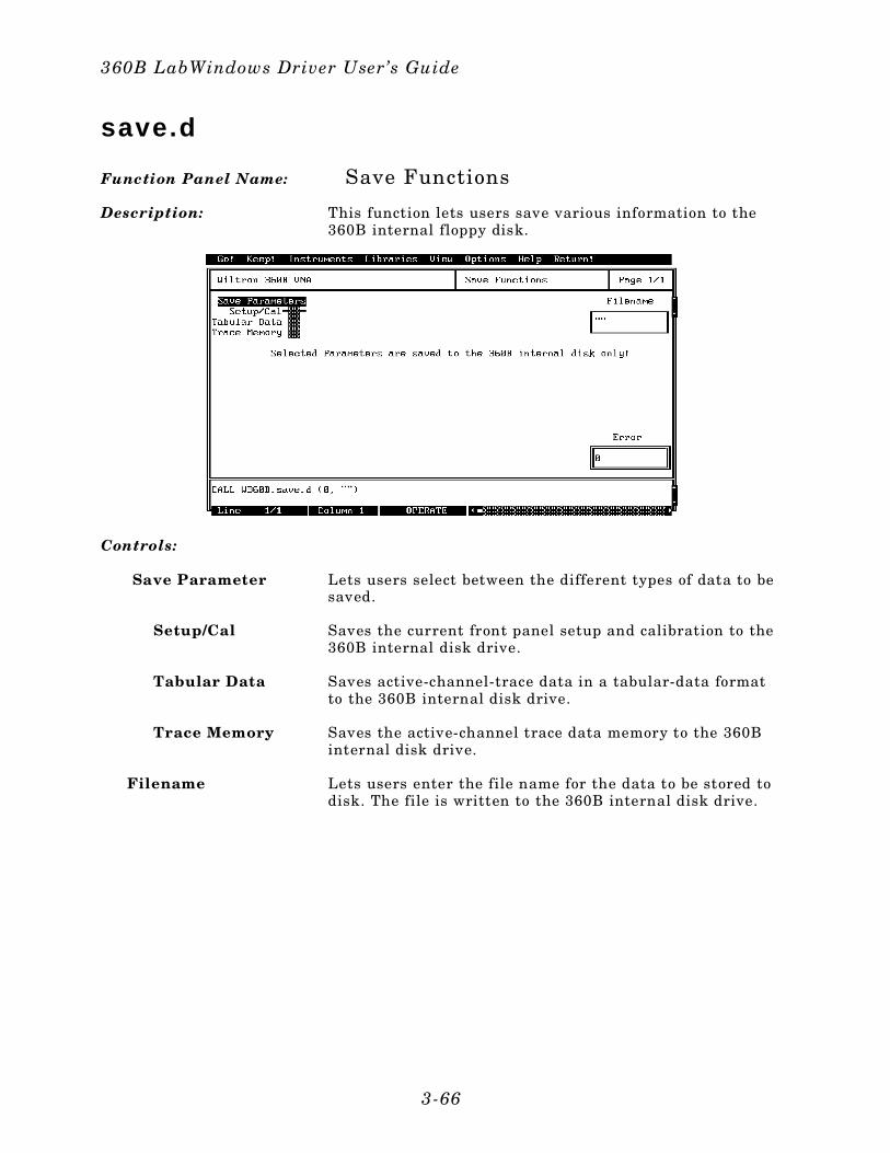
save.d
Function Panel Name: Save Functions
Description: This function lets users save various information to the360B internal floppy disk.
Controls:
Save Parameter Lets users select between the different types of data to besaved.
Setup/Cal Saves the current front panel setup and calibration to the360B internal disk drive.
Tabular Data Saves active-channel-trace data in a tabular-data formatto the 360B internal disk drive.
Trace Memory Saves the active-channel trace data memory to the 360Binternal disk drive.
Filename Lets users enter the file name for the data to be stored todisk. The file is written to the 360B internal disk drive.
360B LabWindows Driver User’s Guide
3-66
Input Parameters: (D) is the default setting.
VariableName
VariableType Descr ipt ion Detai ls
SAVEP% Integer Save parameter 0 = Cal ibrat ion data (D) 1 = Tabular data 2 = Trace Memory Data
FAME$ String File name to save 8 characters, maximum
Output Parameters: None.
Error: LabWindows error codes(220-300). W360B error codes.
Program Examples:
QuickBASIC:
REM Save parameters
CALL W360B.save.d(SAVP%,FAME$)
Microsoft C:
/ * Save parameters */
W360B_save_d(SAVP,FAME)
Section 3
3-67
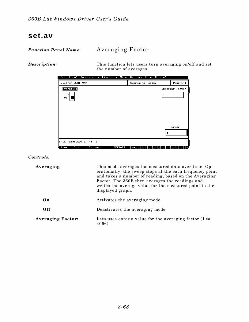
set.av
Function Panel Name: Averaging Factor
Description: This function lets users turn averaging on/off and setthe number of averages.
Controls:
Averaging This mode averages the measured data over time. Op-erationally, the sweep stops at the each frequency pointand takes a number of reading, based on the AveragingFactor. The 360B then averages the readings andwrites the average value for the measured point to thedisplayed graph.
On Activates the averaging mode.
Off Deactivates the averaging mode.
Averaging Factor: Lets uses enter a value for the averaging factor (1 to4096).
360B LabWindows Driver User’s Guide
3-68
Input Parameters: (D) is the default setting.
Var iableName
Var iableType Descript ion Detai ls Range
AVON% Integer Averaging on/off 0 = Off (D)1 = On
AVG% Integer Averaging factor 1 (D) 1 to4096
Output Parameters: None.
Error: LabWindows error codes(220-300). W360B error codes.
Program Examples:
Quick BASIC:
REM Turn Averaging on or o ff and sets averaging factor.
CALL W360B.set .av(AVON%,AVG%)
Microsoft C:
/* Turn Averaging on or off and sets averaging factor. */W360B_set_av(AVON,AVG)
Section 3
3-69
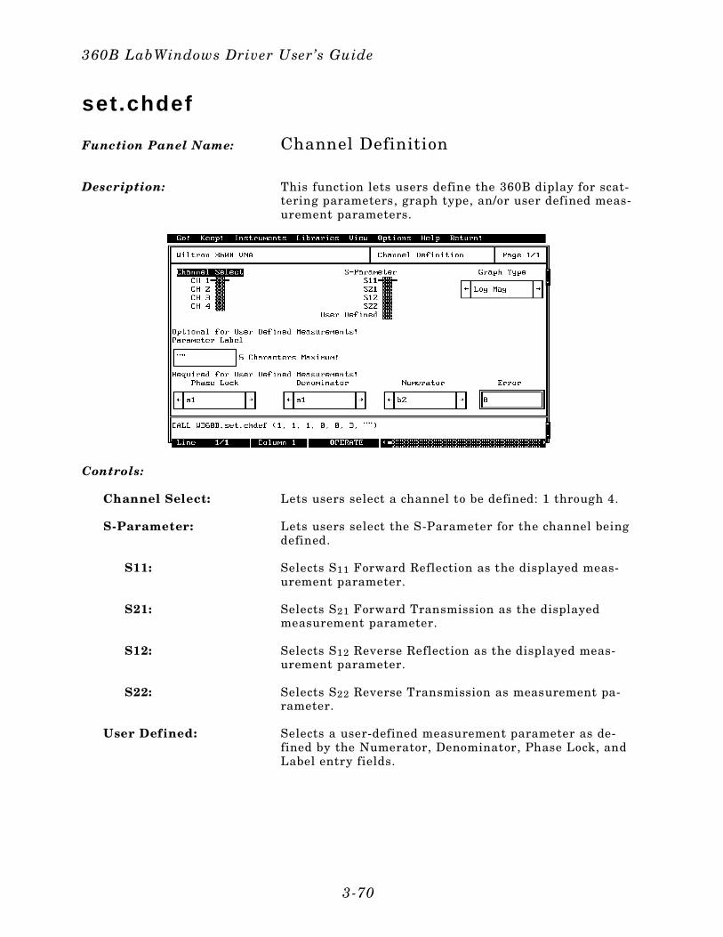
set.chdef
Function Panel Name: Channel Definition
Description: This function lets users define the 360B diplay for scat-tering parameters, graph type, an/or user defined meas-urement parameters.
Controls:
Channel Select: Lets users select a channel to be defined: 1 through 4.
S-Parameter: Lets users select the S-Parameter for the channel beingdefined.
S11: Selects S11 Forward Reflection as the displayed meas-urement parameter.
S21: Selects S21 Forward Transmission as the displayedmeasurement parameter.
S12: Selects S12 Reverse Reflection as the displayed meas-urement parameter.
S22: Selects S22 Reverse Transmission as measurement pa-rameter.
User Defined: Selects a user-defined measurement parameter as de-fined by the Numerator, Denominator, Phase Lock, andLabel entry fields.
360B LabWindows Driver User’s Guide
3-70
Graph Type: Lets users define a graph type for the selected channel:Log Magnitude, Phase, Log Magnitude and Phase,Smith Chart, SWR, Group Delay, Admittance SmithChart, Linear Polar, Log Polar, Linear Magnitude, Lin-ear Magnitude and Phase, Real, Imaginary, Real andImaginary.
Parameter Label: Lets users assign a label for their user-defined parame-ters.
Phase Lock: Lets users select the Phase Lock parameter: a1, a2.
Denominator: Lets users select the Denominator parameter: a1, a2,b1, b2, 1 (unity).
Numerator: Lets users select their Numerator parameter: a1, a2,b1, b2, 1 (unity).
Section 3
3-71
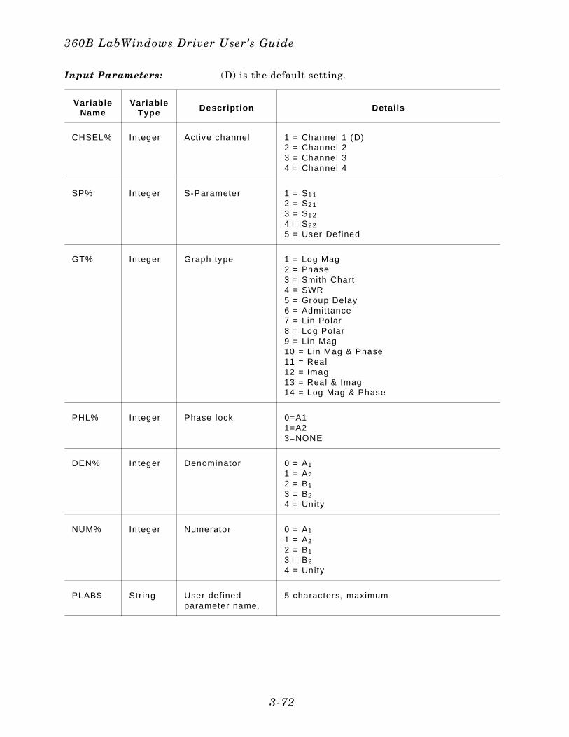
Input Parameters: (D) is the default setting.
VariableName
VariableType Descript ion Detai ls
CHSEL% Integer Active channel 1 = Channel 1 (D)2 = Channel 2 3 = Channel 3 4 = Channel 4
SP% Integer S-Parameter 1 = S11 2 = S21 3 = S12
4 = S22
5 = User Defined
GT% Integer Graph type 1 = Log Mag2 = Phase3 = Smith Chart4 = SWR5 = Group Delay6 = Admittance7 = Lin Polar8 = Log Polar9 = Lin Mag10 = Lin Mag & Phase11 = Real12 = Imag13 = Real & Imag14 = Log Mag & Phase
PHL% Integer Phase lock 0=A1 1=A2 3=NONE
DEN% Integer Denominator 0 = A1 1 = A2 2 = B1 3 = B24 = Unity
NUM% Integer Numerator 0 = A1 1 = A2 2 = B1 3 = B2 4 = Unity
PLAB$ String User definedparameter name.
5 characters, maximum
360B LabWindows Driver User’s Guide
3-72
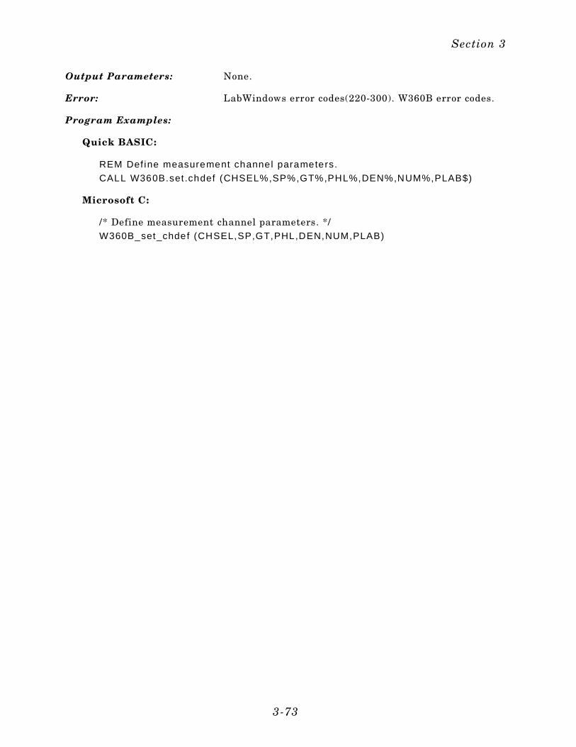
Output Parameters: None.
Error: LabWindows error codes(220-300). W360B error codes.
Program Examples:
Quick BASIC:
REM Def ine measurement channel parameters.
CALL W360B.set .chdef (CHSEL%,SP%,GT%,PHL%,DEN%,NUM%,PLAB$)
Microsoft C:
/* Define measurement channel parameters. */W360B_set_chdef (CHSEL,SP,GT,PHL,DEN,NUM,PLAB)
Section 3
3-73
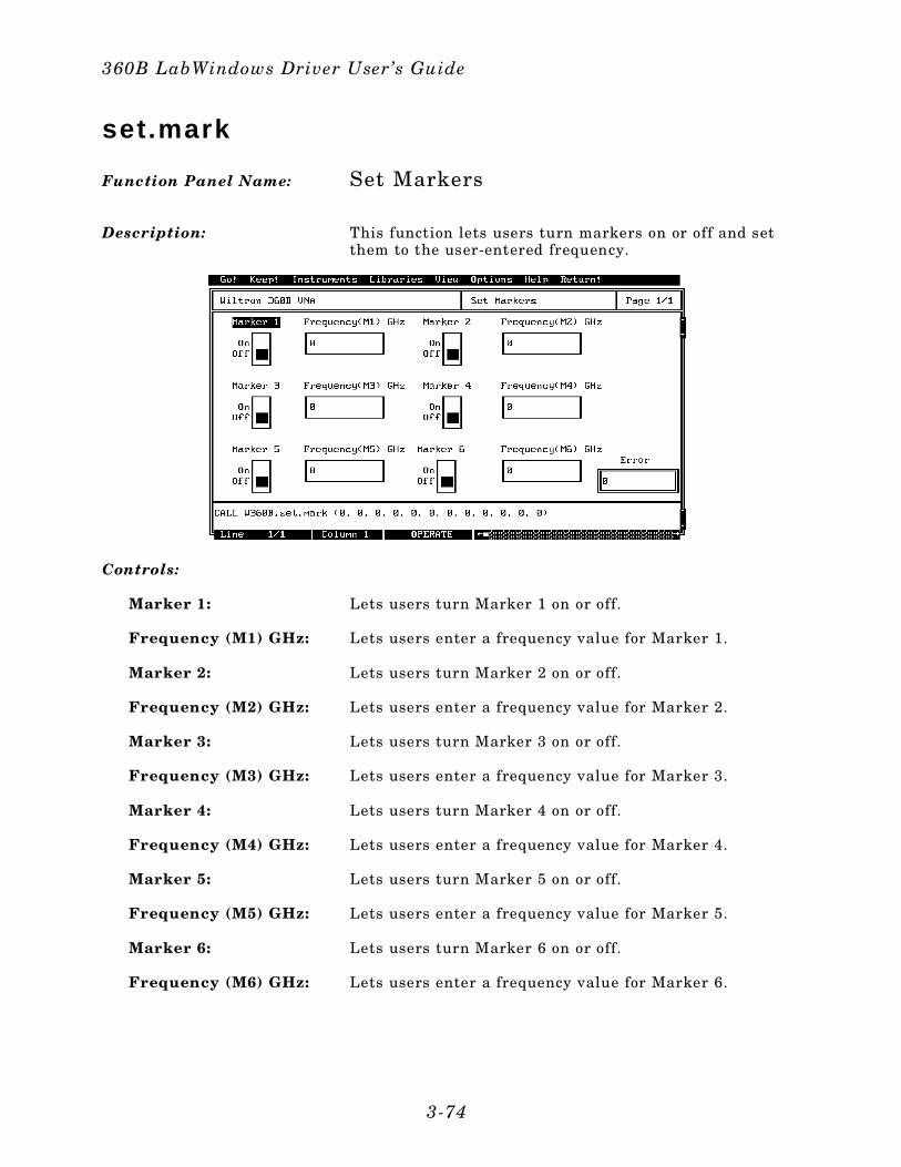
set.mark
Function Panel Name: Set Markers
Description: This function lets users turn markers on or off and setthem to the user-entered frequency.
Controls:
Marker 1: Lets users turn Marker 1 on or off.
Frequency (M1) GHz: Lets users enter a frequency value for Marker 1.
Marker 2: Lets users turn Marker 2 on or off.
Frequency (M2) GHz: Lets users enter a frequency value for Marker 2.
Marker 3: Lets users turn Marker 3 on or off.
Frequency (M3) GHz: Lets users enter a frequency value for Marker 3.
Marker 4: Lets users turn Marker 4 on or off.
Frequency (M4) GHz: Lets users enter a frequency value for Marker 4.
Marker 5: Lets users turn Marker 5 on or off.
Frequency (M5) GHz: Lets users enter a frequency value for Marker 5.
Marker 6: Lets users turn Marker 6 on or off.
Frequency (M6) GHz: Lets users enter a frequency value for Marker 6.
360B LabWindows Driver User’s Guide
3-74
Input Parameters: (D) is the default setting.
Var iableName
Var iableType Descr ipt ion Detai ls Range
MKx% Integer Marker x on/off(x = marker to set)
0 = Off(D)1 = On
1 to 9
MKFx# Real Marker frequency(x = marker to set)
GHz
Output Parameters: None.
Error: LabWindows error codes(220-300). W360B error codes.
Program Examples:
Quick BASIC:
REM Set markers.
CALL W360B.set .mark(MK1%,MKF1#,MK2%,MKF2#,MK3%,MKF3#,MK4%,MKF4#,MK5%,MKF5#,MK6%,MKF6#)
Microsoft C:
/ * Set markers. */
W360B_set_mark(MK1,MKF1,MK2,MKF2,MK3,MKF3,MK4,MKF4,MK5,MKF5,MK6,MKF6)
Section 3
3-75
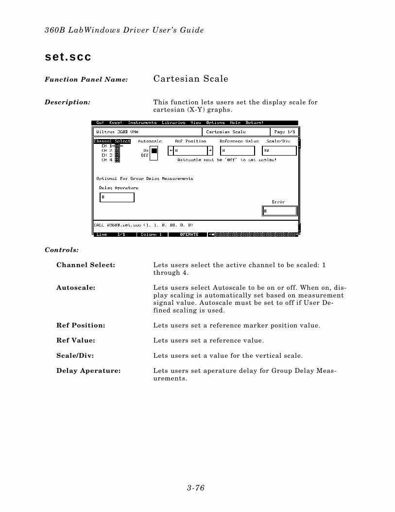
set.scc
Function Panel Name: Cartesian Scale
Description: This function lets users set the display scale forcartesian (X-Y) graphs.
Controls:
Channel Select: Lets users select the active channel to be scaled: 1through 4.
Autoscale: Lets users select Autoscale to be on or off. When on, dis-play scaling is automatically set based on measurementsignal value. Autoscale must be set to off if User De-fined scaling is used.
Ref Position: Lets users set a reference marker position value.
Ref Value: Lets users set a reference value.
Scale/Div: Lets users set a value for the vertical scale.
Delay Aperature: Lets users set aperature delay for Group Delay Meas-urements.
360B LabWindows Driver User’s Guide
3-76
Input Parameters: (D) is the default setting.
Var iableName
Var iableType Descript ion Detai ls Range
CHSEL% Integer Active channel 1 = Channel 1 (D)2 = Channel 2 3 = Channel 3 4 = Channel 4
AC% Integer Autoscale 0 = Off1 = On (D)
REFP% Integer Reference posit ion 0 (D) 1 thru 8
SCALE# Real Scale for d isplay 10 (D) 0.01 to 90 degreesper div ision
REFV# Real Reference value 0 (D)
GD# Real Delay aperature 0 (D) 0 to 20%
Output Parameters: None.
Error: LabWindows error codes(220-300). W360B error codes.
Program Examples:
Quick BASIC:
REM Set cartesian scale va lues.
CALL W360B.set .scc(CHSEL%,AC%,REFP%,SCALE#,REFV#,GD#)
Microsoft C:
/ * Set cartesian scale values. * /
W360B_set_scc(CHSEL,AC,REFP,SCALE,REFV,GD)
Section 3
3-77
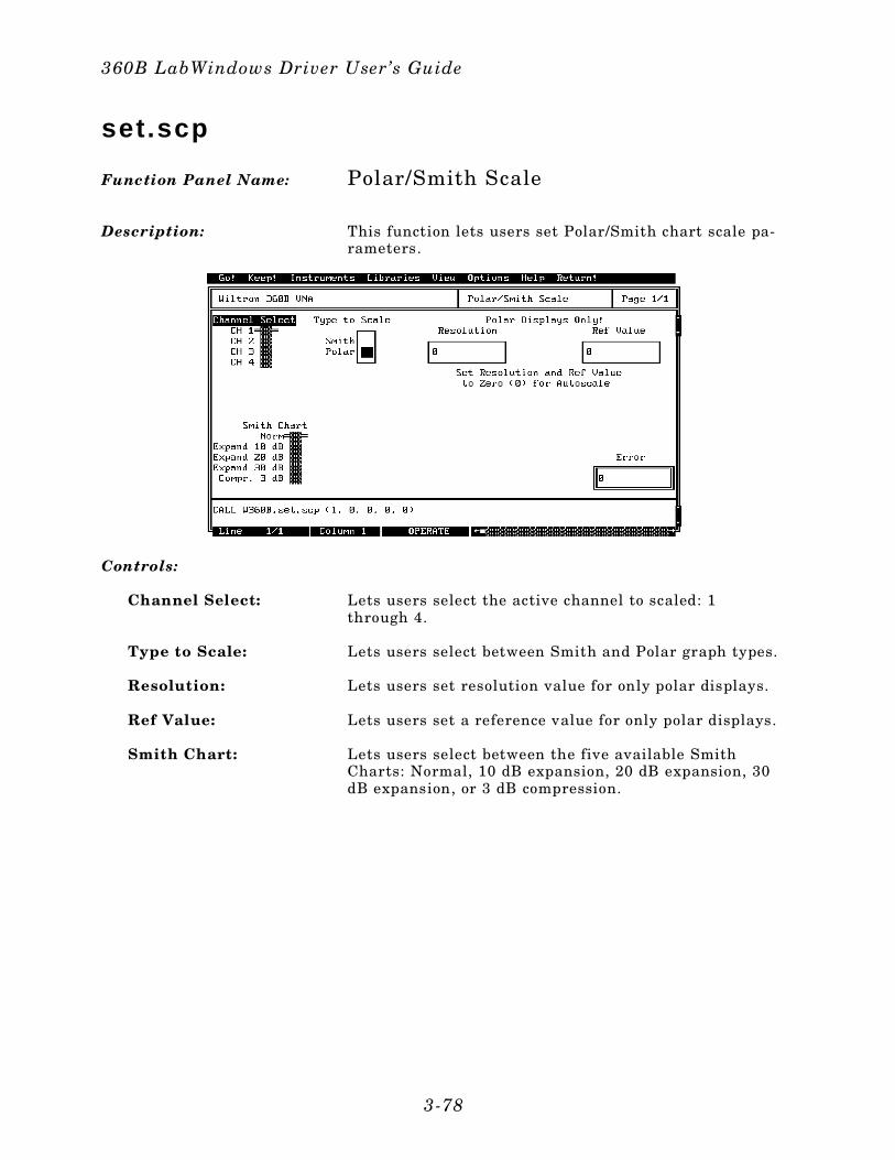
set.scp
Function Panel Name: Polar/Smith Scale
Description: This function lets users set Polar/Smith chart scale pa-rameters.
Controls:
Channel Select: Lets users select the active channel to scaled: 1through 4.
Type to Scale: Lets users select between Smith and Polar graph types.
Resolution: Lets users set resolution value for only polar displays.
Ref Value: Lets users set a reference value for only polar displays.
Smith Chart: Lets users select between the five available SmithCharts: Normal, 10 dB expansion, 20 dB expansion, 30dB expansion, or 3 dB compression.
360B LabWindows Driver User’s Guide
3-78
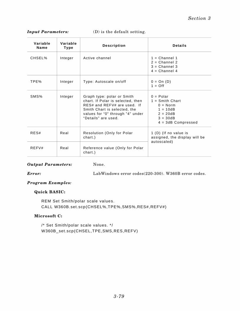
Input Parameters: (D) is the default setting.
Var iableName
Var iableType Descript ion Detai ls
CHSEL% Integer Active channel 1 = Channel 1 2 = Channel 2 3 = Channel 3 4 = Channel 4
TPE% Integer Type: Autoscale on/off 0 = On (D)1 = Off
SMS% Integer Graph type: polar or Smithchart. I f Polar is selected, thenRES# and REFV# are used. I fSmith Char t is selected, thevalues for “0" through ”4" under“Detai ls” are used.
0 = Polar 1 = Smith Chart
0 = Norm 1 = 10dB 2 = 20dB 3 = 30dB 4 = 3dB Compressed
RES# Real Resolut ion (Only for Polarchart.)
1 (D) (I f no value isassigned, the display wi l l beautoscaled)
REFV# Real Reference value (Only for Polarchart.)
Output Parameters: None.
Error: LabWindows error codes(220-300). W360B error codes.
Program Examples:
Quick BASIC:
REM Set Smi th/polar scale va lues.
CALL W360B.set .scp(CHSEL%,TPE%,SMS%,RES#,REFV#)
Microsoft C:
/ * Set Smith/polar scale values. * /
W360B_set.scp(CHSEL,TPE,SMS,RES,REFV)
Section 3
3-79
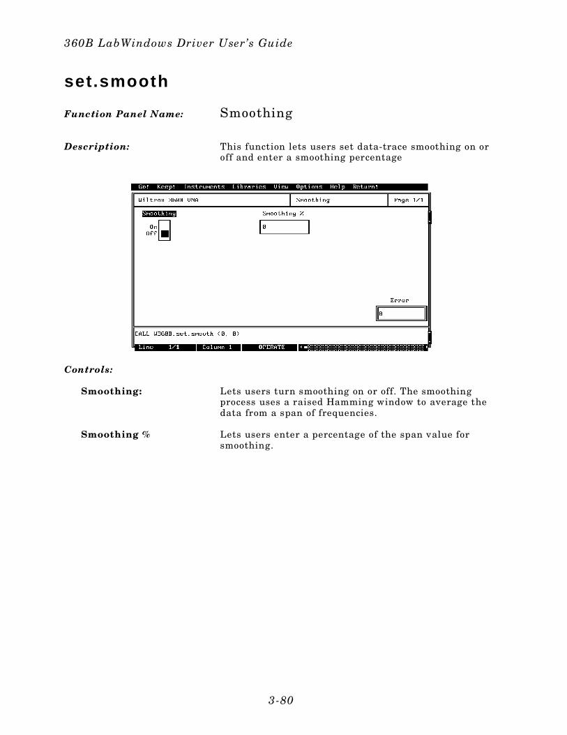
set.smooth
Function Panel Name: Smoothing
Description: This function lets users set data-trace smoothing on oroff and enter a smoothing percentage
Controls:
Smoothing: Lets users turn smoothing on or off. The smoothingprocess uses a raised Hamming window to average thedata from a span of frequencies.
Smoothing % Lets users enter a percentage of the span value forsmoothing.
360B LabWindows Driver User’s Guide
3-80
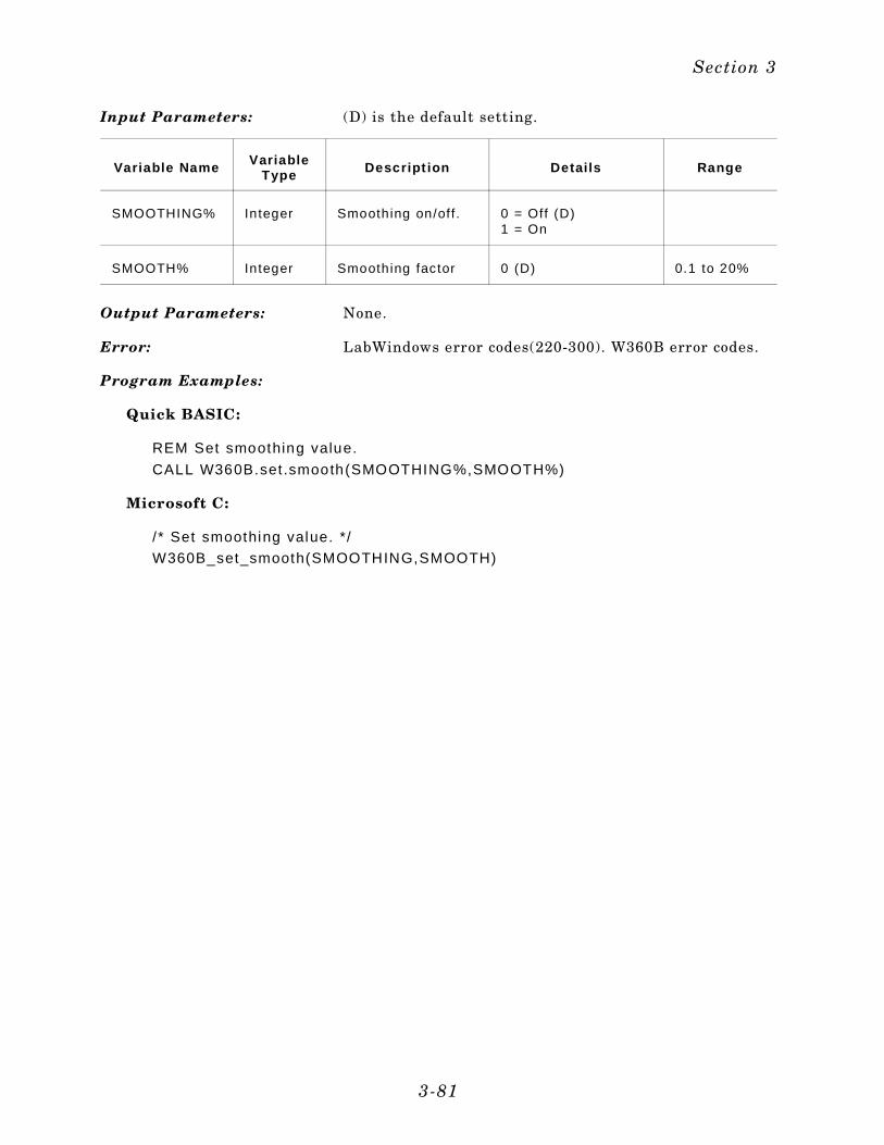
Input Parameters: (D) is the default setting.
Variable Name VariableType Descript ion Detai ls Range
SMOOTHING% Integer Smoothing on/off . 0 = Off (D)1 = On
SMOOTH% Integer Smoothing factor 0 (D) 0.1 to 20%
Output Parameters: None.
Error: LabWindows error codes(220-300). W360B error codes.
Program Examples:
Quick BASIC:
REM Set smoothing value.
CALL W360B.set .smooth(SMOOTHING%,SMOOTH%)
Microsoft C:
/ * Set smoothing value. */
W360B_set_smooth(SMOOTHING,SMOOTH)
Section 3
3-81
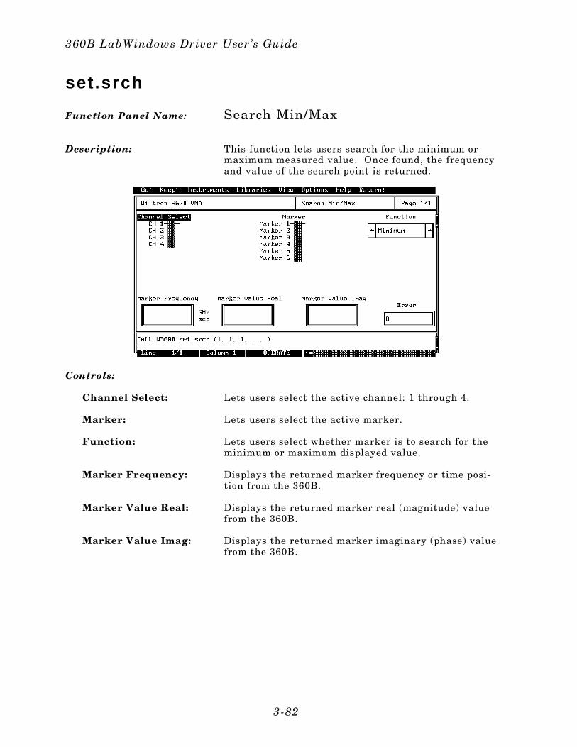
set.srch
Function Panel Name: Search Min/Max
Description: This function lets users search for the minimum ormaximum measured value. Once found, the frequencyand value of the search point is returned.
Controls:
Channel Select: Lets users select the active channel: 1 through 4.
Marker: Lets users select the active marker.
Function: Lets users select whether marker is to search for theminimum or maximum displayed value.
Marker Frequency: Displays the returned marker frequency or time posi-tion from the 360B.
Marker Value Real: Displays the returned marker real (magnitude) valuefrom the 360B.
Marker Value Imag: Displays the returned marker imaginary (phase) valuefrom the 360B.
360B LabWindows Driver User’s Guide
3-82
Input Parameters: (D) is the default setting.
Var iableName
Var iableType Descript ion Detai ls Range
CHSEL% Integer Active channel 1 = Channel 1 (D)2 = Channel 2 3 = Channel 3 4 = Channel 4
MK% Integer Marker selected 1 = Marker 1 (D) 1 thru 6
FUNC% Integer Marker function 1 = Marker to minimum (D)2 = Marker to Maximum returned variables
MKV# Real Marker real value
MKVI# Real Marker imaginaryvalue
MKVF# Real Marker frequency
Output Parameters: None.
Error: LabWindows error codes(220-300). W360B error codes.
Program Examples:
Quick BASIC:
REM Sets marker min/max search value.
CALL W360B.set .srch(MK%,FUNC%,MKV#,MKVI#,MKVF#)
Microsoft C:
/ * */
W360B_set_srch(MK,FUNC,MKV,MKVI,MKVF)
Section 3
3-83
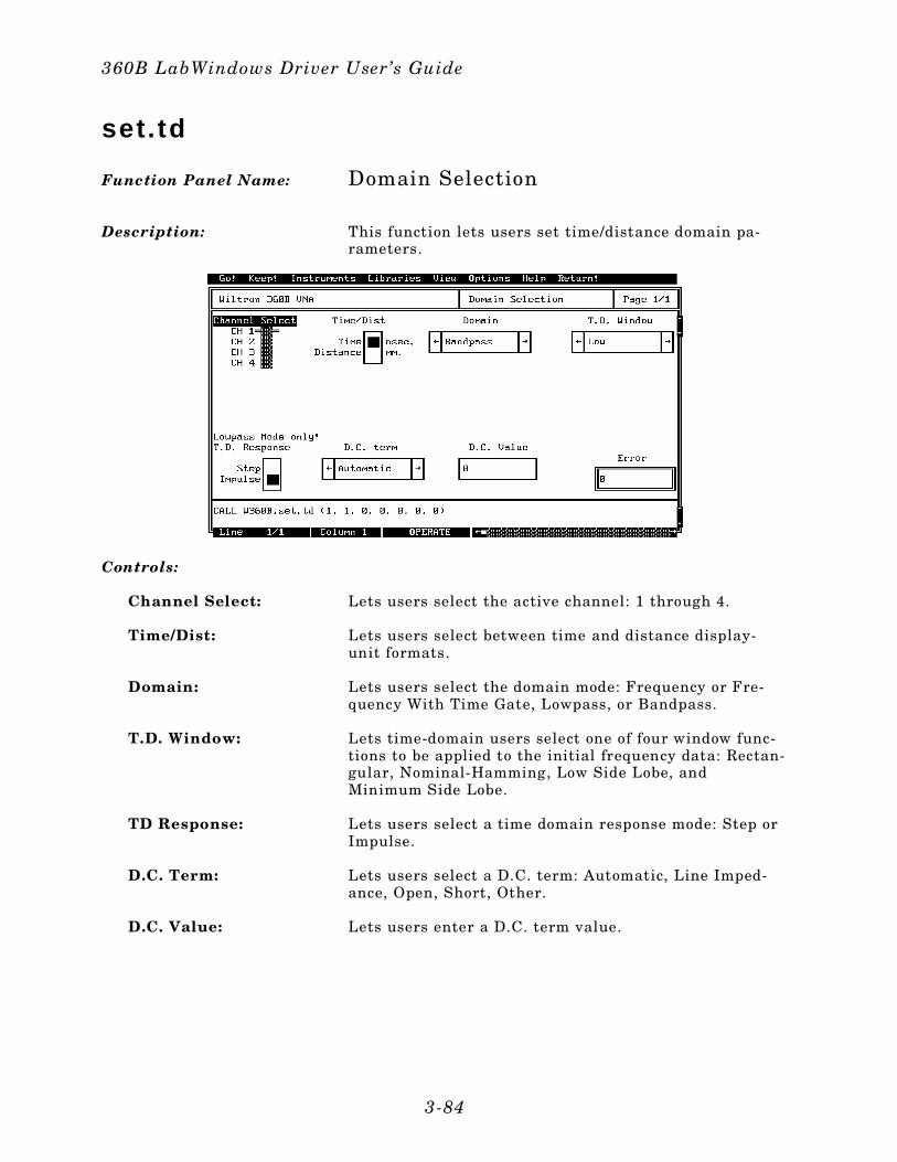
set. td
Function Panel Name: Domain Selection
Description: This function lets users set time/distance domain pa-rameters.
Controls:
Channel Select: Lets users select the active channel: 1 through 4.
Time/Dist: Lets users select between time and distance display-unit formats.
Domain: Lets users select the domain mode: Frequency or Fre-quency With Time Gate, Lowpass, or Bandpass.
T.D. Window: Lets time-domain users select one of four window func-tions to be applied to the initial frequency data: Rectan-gular, Nominal-Hamming, Low Side Lobe, andMinimum Side Lobe.
TD Response: Lets users select a time domain response mode: Step orImpulse.
D.C. Term: Lets users select a D.C. term: Automatic, Line Imped-ance, Open, Short, Other.
D.C. Value: Lets users enter a D.C. term value.
360B LabWindows Driver User’s Guide
3-84

Input Parameters: (D) is the default setting.
Var iableName
VariableType Descript ion Detai ls
CHSEL% Integer Active channel 1 = Channel 1 (D)2 = Channel 2 3 = Channel 3 4 = Channel 4
TD% Integer Time/distance 1 = Time (D)0 = Distance
DOM% Integer Time domain mode 0 = Bandpass (D) 1 = Lowpass2 = Phasor Imp3 = Frequency4 = Frequency to T.G.
TDWIN% Integer Time DomainWindow
0 = Low (D)1 = Minimum 2 = Normal 3 = Rectangular
TDRES% Integer Time domainresponse
0 = Impulse (D)1 = Step
DCRES% Integer Direct currentresistance
0 = Automatic (D) 1 = Open 2 = Shor t 3 = Entered
DCVALUE# Real Value
Output Parameters: None.
Error: LabWindows error codes(220-300). W360B error codes
Program Examples:
Quick BASIC:
REM Selects t ime or d istance domains and sets values.
CALLW360B.set . td(CHSEL%,TD%,DOM%,TDWIN%,TDRES%,DCRES%,DCVALUE#)
Microsoft C:
/ * Selects time or distance domains and sets values. */
W360B_set_td(CHSEL,TD,DOM,TDWIN,TDRES,DCRES,DCVALUE)
Section 3
3-85
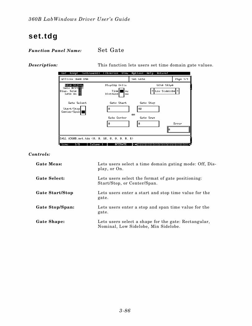
set. tdg
Function Panel Name: Set Gate
Description: This function lets users set time domain gate values.
Controls:
Gate Meas: Lets users select a time domain gating mode: Off, Dis-play, or On.
Gate Select: Lets users select the format of gate positioning:Start/Stop, or Center/Span.
Gate Start/Stop Lets users enter a start and stop time value for thegate.
Gate Stop/Span: Lets users enter a stop and span time value for thegate.
Gate Shape: Lets users select a shape for the gate: Rectangular,Nominal, Low Sidelobe, Min Sidelobe.
360B LabWindows Driver User’s Guide
3-86
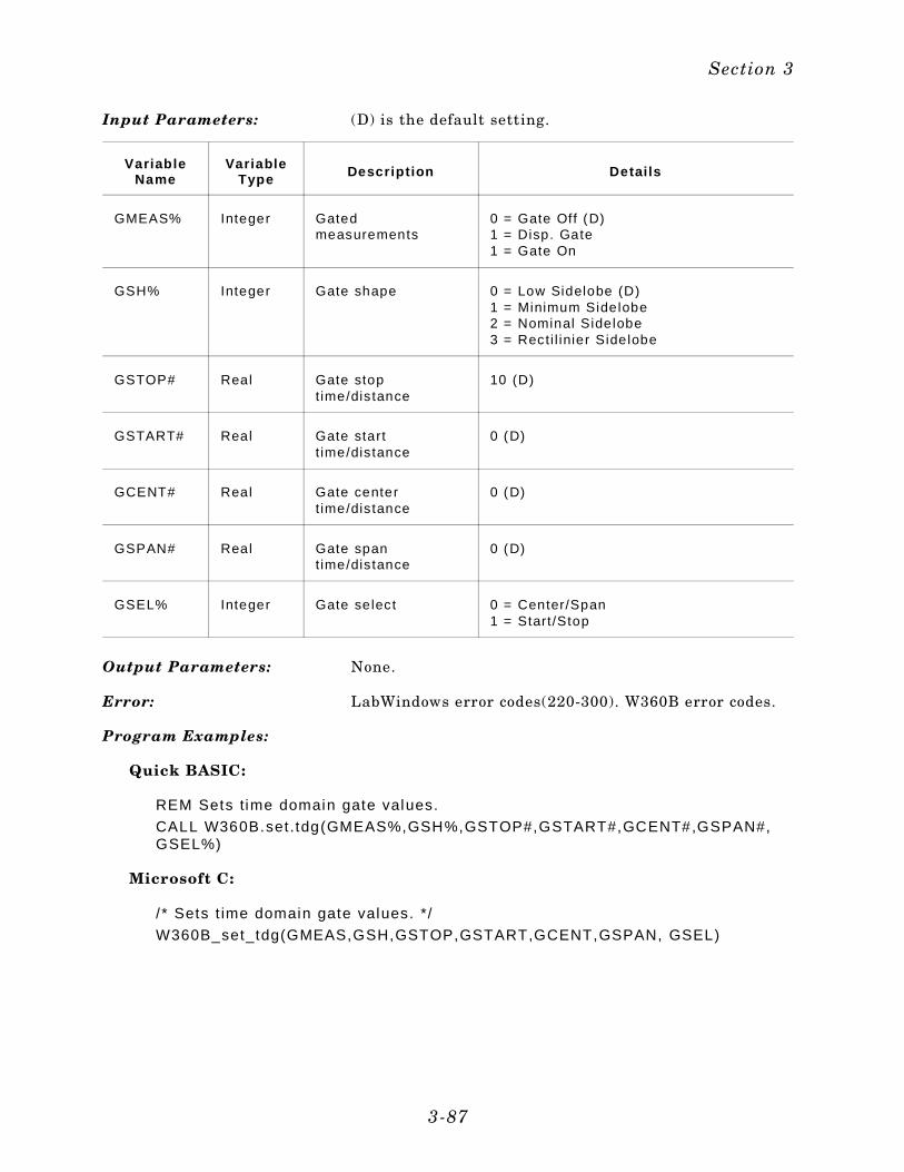
Input Parameters: (D) is the default setting.
VariableName
VariableType Descript ion Detai ls
GMEAS% Integer Gatedmeasurements
0 = Gate Off (D)1 = Disp. Gate1 = Gate On
GSH% Integer Gate shape 0 = Low Sidelobe (D)1 = Minimum Sidelobe2 = Nominal Sidelobe 3 = Recti l inier Sidelobe
GSTOP# Real Gate stoptime/distance
10 (D)
GSTART# Real Gate startt ime/distance
0 (D)
GCENT# Real Gate centert ime/distance
0 (D)
GSPAN# Real Gate spantime/distance
0 (D)
GSEL% Integer Gate select 0 = Center/Span1 = Start/Stop
Output Parameters: None.
Error: LabWindows error codes(220-300). W360B error codes.
Program Examples:
Quick BASIC:
REM Sets time domain gate values.
CALL W360B.set .tdg(GMEAS%,GSH%,GSTOP#,GSTART#,GCENT#,GSPAN#,GSEL%)
Microsoft C:
/ * Sets t ime domain gate values. */
W360B_set_tdg(GMEAS,GSH,GSTOP,GSTART,GCENT,GSPAN, GSEL)
Section 3
3-87
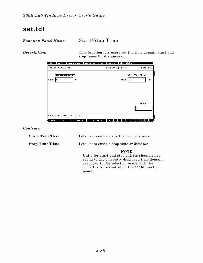
set. tdt
Function Panel Name: Start/Stop Time
Description: This function lets users set the time domain start andstop times (or distances).
Controls:
Start Time/Dist: Lets users enter a start time or distance.
Stop Time/Dist: Lets users enter a stop time or distance.
NOTEUnits for start and stop entries should corre-spond to the currently displayed time domaingraph, or to the selection made with theTime/Distance control on the set.td functionpanel.
360B LabWindows Driver User’s Guide
3-88
Input Parameters: (D) is the default setting.
VariableName
VariableType Descript ion Detai ls
START# Real Start t ime/distance 0 mm/ns (D)
STOPT# Real Stop t ime/distance 0 mm/ns (D)
Output Parameters: None.
Error: LabWindows error codes(220-300). W360B error codes.
Program Examples:
Quick BASIC:
REM Sets start and stop times or frequencies.
CALL W360B.set .tdt(START#,STOPT#)
Microsoft C:
/ * Sets start and stop t imes or f requencies. * /
W360B_set_tdt(START,STOPT)
Section 3
3-89
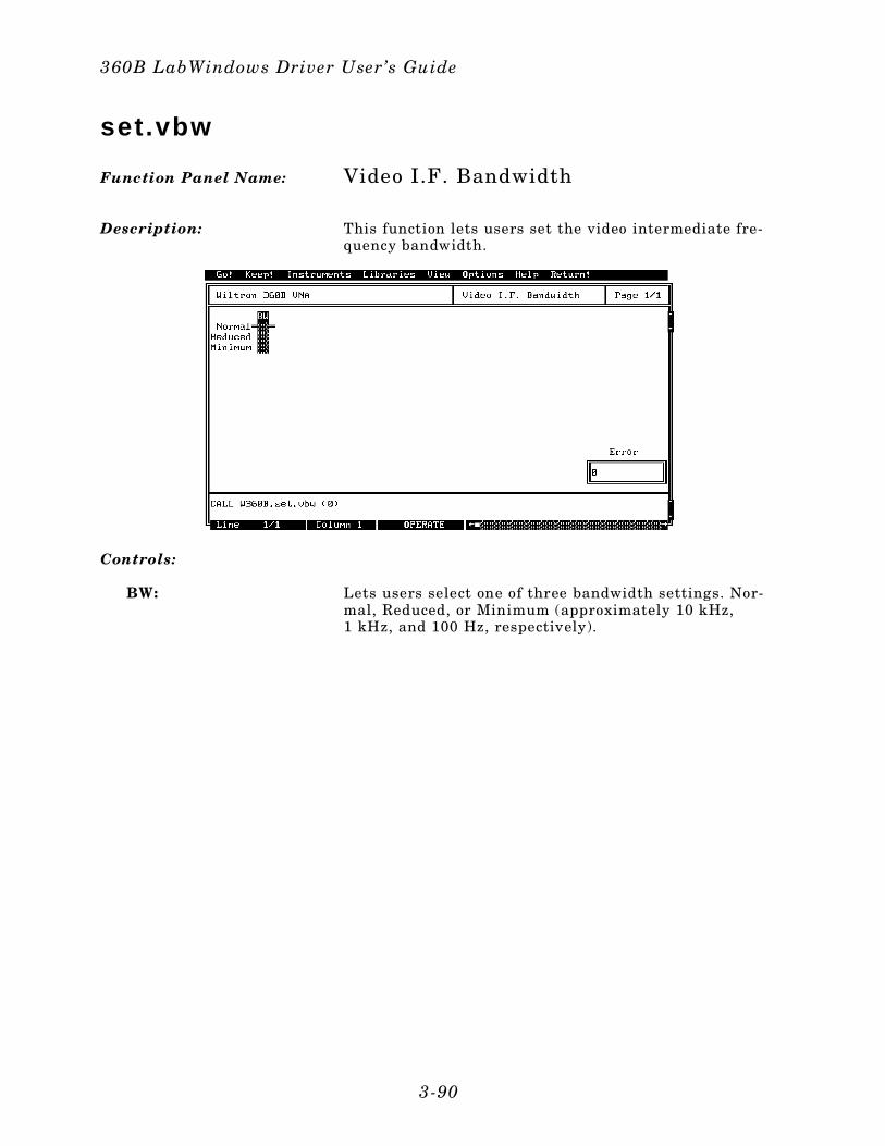
set.vbw
Function Panel Name: Video I.F. Bandwidth
Description: This function lets users set the video intermediate fre-quency bandwidth.
Controls:
BW: Lets users select one of three bandwidth settings. Nor-mal, Reduced, or Minimum (approximately 10 kHz,1 kHz, and 100 Hz, respectively).
360B LabWindows Driver User’s Guide
3-90
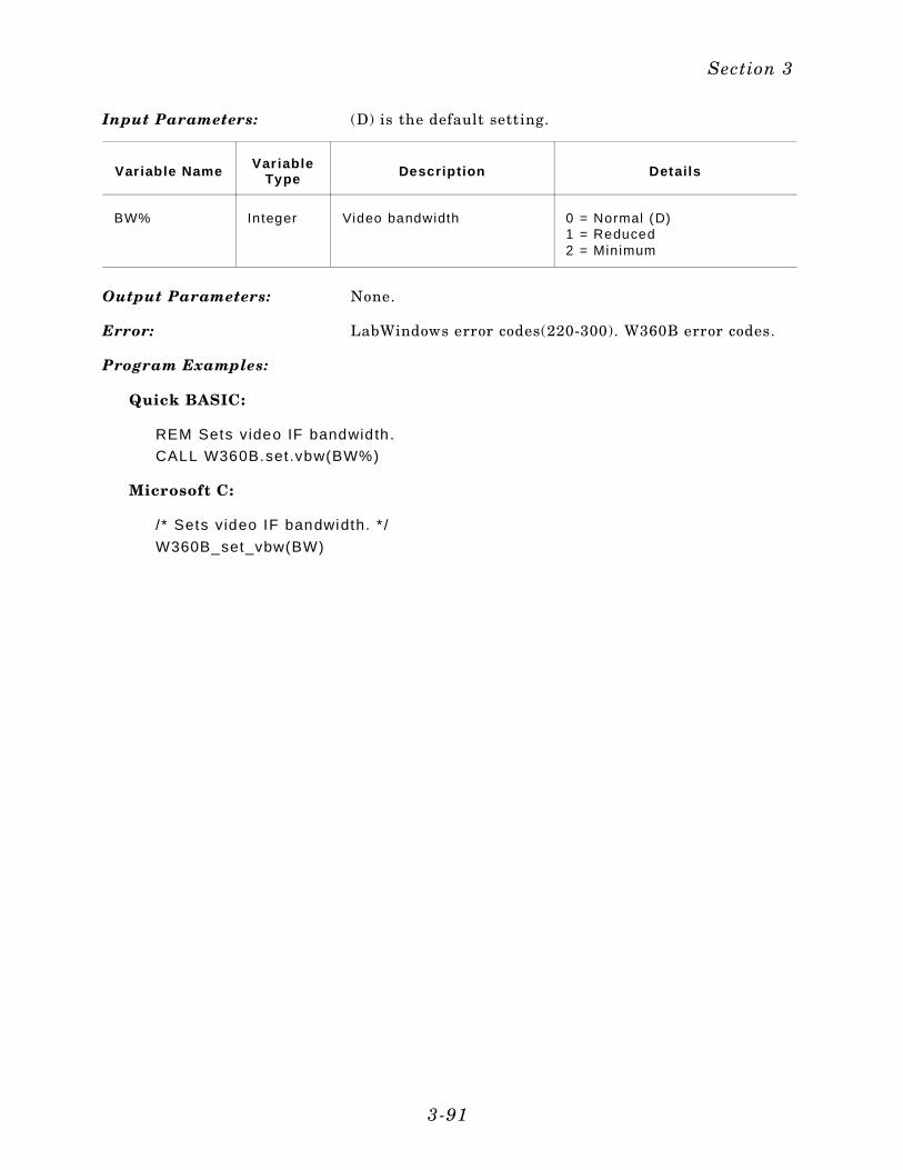
Input Parameters: (D) is the default setting.
Var iable Name Var iableType Descript ion Detai ls
BW% Integer Video bandwidth 0 = Normal (D)1 = Reduced2 = Minimum
Output Parameters: None.
Error: LabWindows error codes(220-300). W360B error codes.
Program Examples:
Quick BASIC:
REM Sets video IF bandwidth.
CALL W360B.set .vbw(BW%)
Microsoft C:
/ * Sets video IF bandwidth. * /
W360B_set_vbw(BW)
Section 3
3-91

set.vnad
Function Panel Name: Channel Display Mode
Description: This function lets users set the 360B channel displaymode.
Controls:
Display Channel:
Single Chan: Single channel display of data on a single channel 1, 2,3, or 4.
CH1 & CH3: Dual channel display of data on channels 1 and 3.
Overlay 1&3:(360B only)
Trace data appearing on channel 1 is overlayed (super-imposed) on channel 3 trace.
CH2 & CH4: Dual channel display of data on channels 2 and 4.
Overlay 2&4:(360B only)
Trace data appearing on measurement channel 2 is over-layed (superimposed) on channel 4 trace data.
4 CH Display: All four display channels are shown simultaneously.
360B LabWindows Driver User’s Guide
3-92

Input Parameters: (D) is the default setting.
VariableName
VariableType Descript ion Detai ls
CHD% Integer Type of display 0 = Single Channel (D)1 = Channel 1 and Channel 3 2 = Overlay Channel 1 and 3 3 = Channel 2 and Channel 4 4 = Overlay Channel 2 and 4 5 = 4 Channel Display
Output Parameters: None.
Error: LabWindows error codes(220-300). W360B error codes.
Program Examples:
Quick BASIC:
REM Sets the disp lay mode.
CALL W360B.set .vnad(CHD%)
Microsoft C:
/ * Sets the display mode. * /
W360B_set_vnad(CHD)
Section 3
3-93
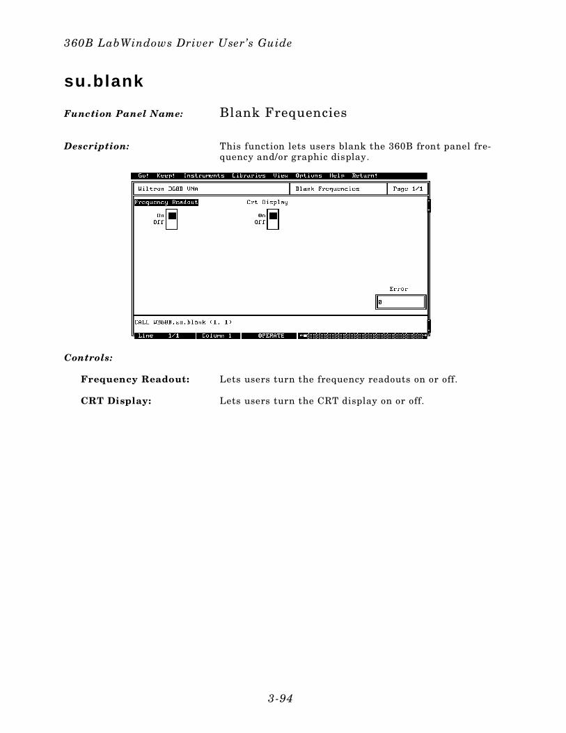
su.blank
Function Panel Name: Blank Frequencies
Description: This function lets users blank the 360B front panel fre-quency and/or graphic display.
Controls:
Frequency Readout: Lets users turn the frequency readouts on or off.
CRT Display: Lets users turn the CRT display on or off.
360B LabWindows Driver User’s Guide
3-94
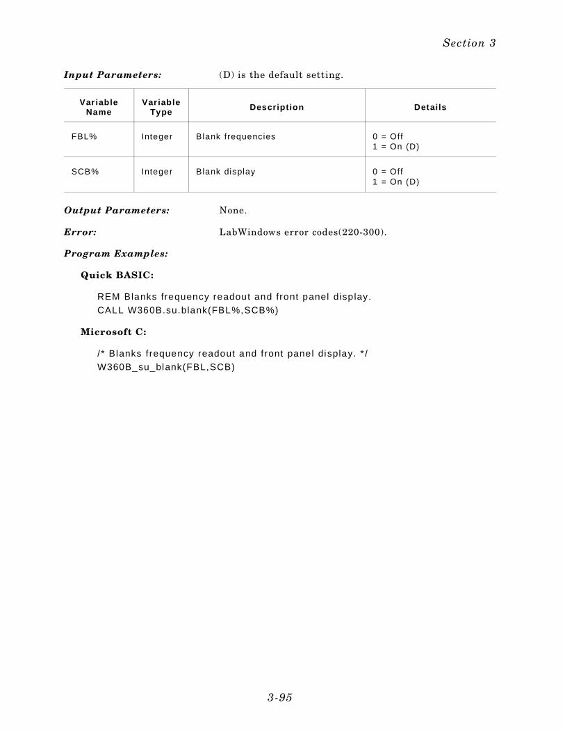
Input Parameters: (D) is the default setting.
Var iableName
Var iableType Descript ion Detai ls
FBL% Integer Blank frequencies 0 = Off1 = On (D)
SCB% Integer Blank display 0 = Off1 = On (D)
Output Parameters: None.
Error: LabWindows error codes(220-300).
Program Examples:
Quick BASIC:
REM Blanks frequency readout and front panel disp lay.
CALL W360B.su.blank(FBL%,SCB%)
Microsoft C:
/ * Blanks f requency readout and f ront panel display. * /
W360B_su_blank(FBL,SCB)
Section 3
3-95
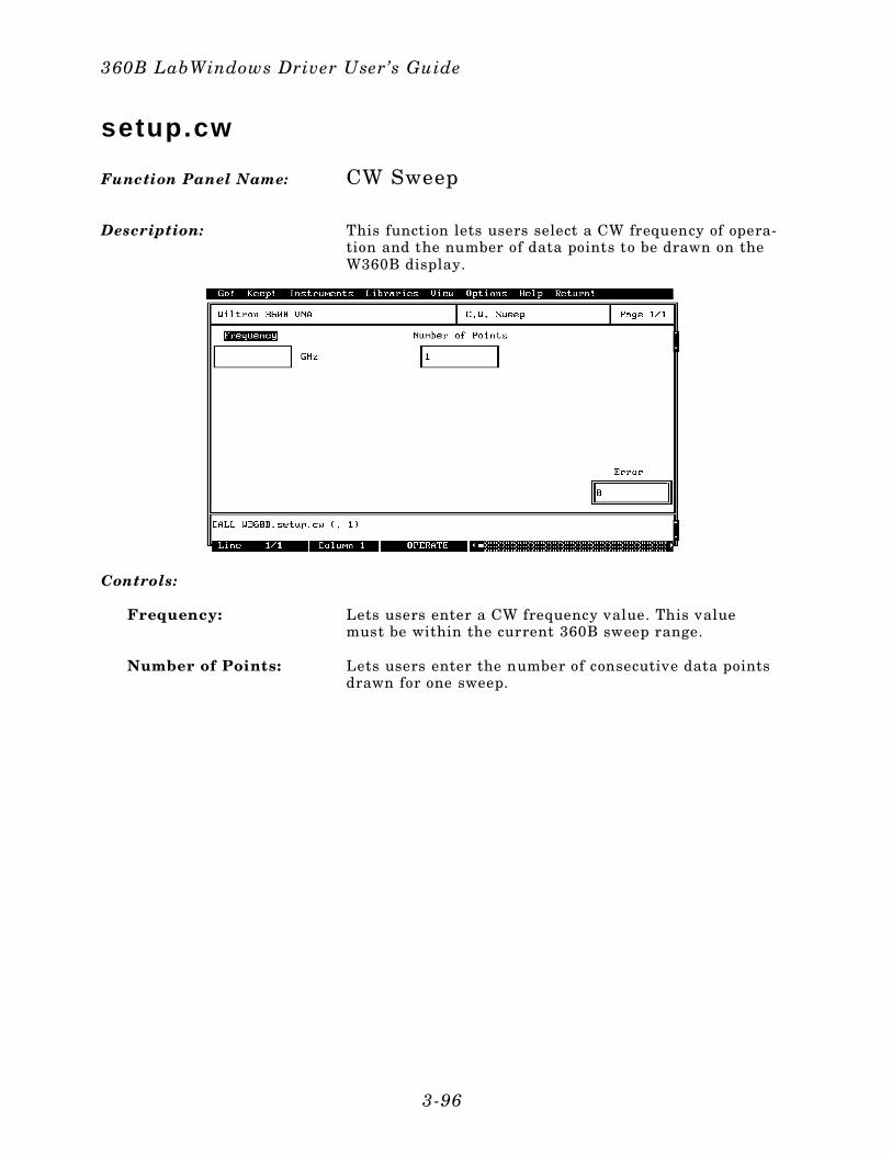
setup.cw
Function Panel Name: CW Sweep
Description: This function lets users select a CW frequency of opera-tion and the number of data points to be drawn on theW360B display.
Controls:
Frequency: Lets users enter a CW frequency value. This valuemust be within the current 360B sweep range.
Number of Points: Lets users enter the number of consecutive data pointsdrawn for one sweep.
360B LabWindows Driver User’s Guide
3-96
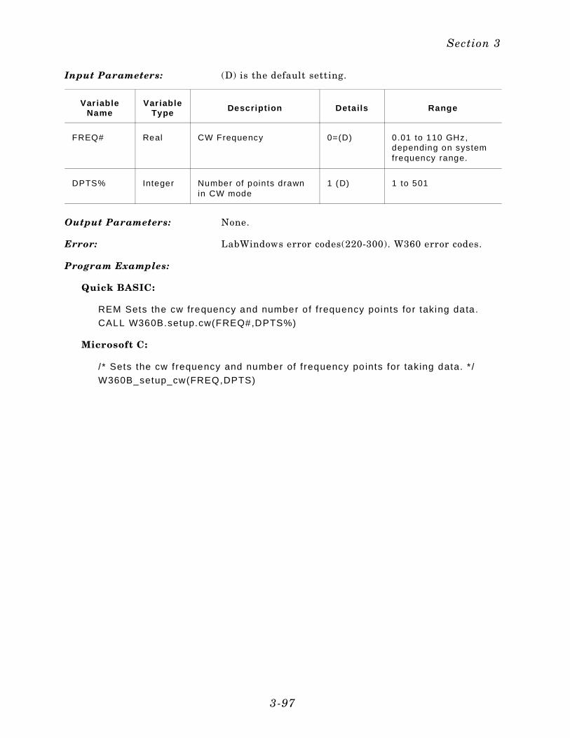
Input Parameters: (D) is the default setting.
Var iableName
Var iableType Descript ion Detai ls Range
FREQ# Real CW Frequency 0=(D) 0.01 to 110 GHz,depending on systemfrequency range.
DPTS% Integer Number of points drawnin CW mode
1 (D) 1 to 501
Output Parameters: None.
Error: LabWindows error codes(220-300). W360 error codes.
Program Examples:
Quick BASIC:
REM Sets the cw frequency and number of f requency points for taking data.
CALL W360B.setup.cw(FREQ#,DPTS%)
Microsoft C:
/ * Sets the cw frequency and number of f requency po ints for taking data. * /
W360B_setup_cw(FREQ,DPTS)
Section 3
3-97
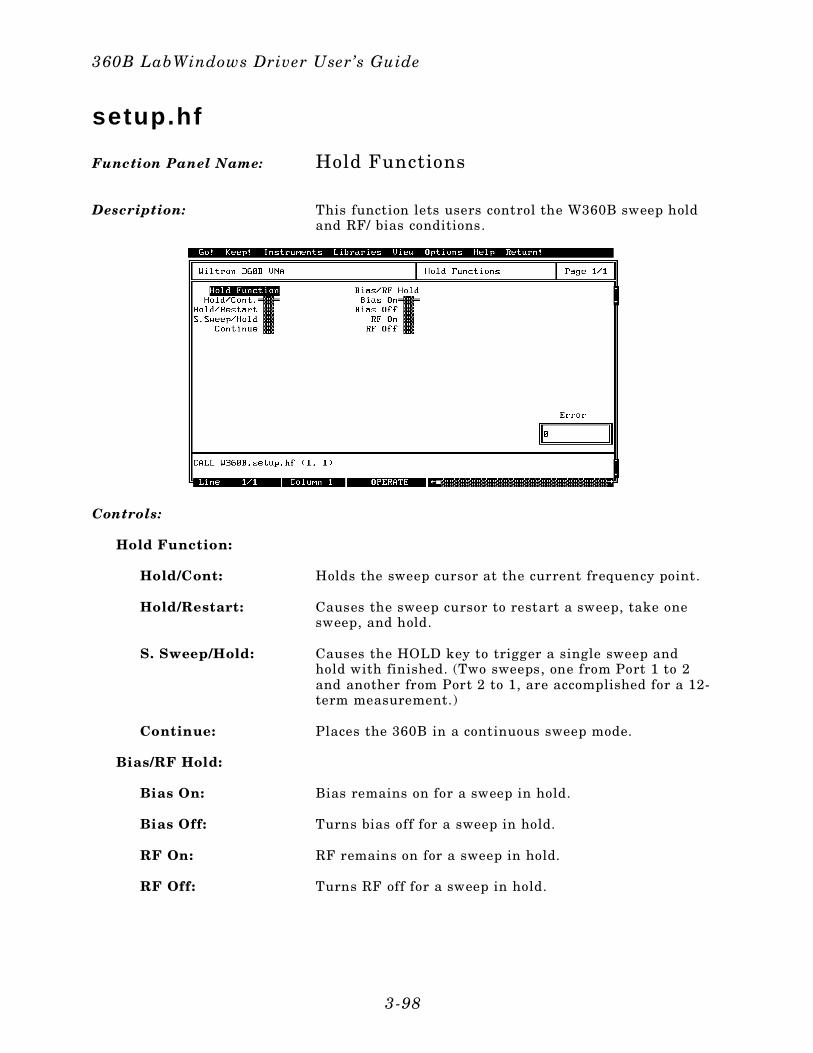
setup.hf
Function Panel Name: Hold Functions
Description: This function lets users control the W360B sweep holdand RF/ bias conditions.
Controls:
Hold Function:
Hold/Cont: Holds the sweep cursor at the current frequency point.
Hold/Restart: Causes the sweep cursor to restart a sweep, take onesweep, and hold.
S. Sweep/Hold: Causes the HOLD key to trigger a single sweep andhold with finished. (Two sweeps, one from Port 1 to 2and another from Port 2 to 1, are accomplished for a 12-term measurement.)
Continue: Places the 360B in a continuous sweep mode.
Bias/RF Hold:
Bias On: Bias remains on for a sweep in hold.
Bias Off: Turns bias off for a sweep in hold.
RF On: RF remains on for a sweep in hold.
RF Off: Turns RF off for a sweep in hold.
360B LabWindows Driver User’s Guide
3-98
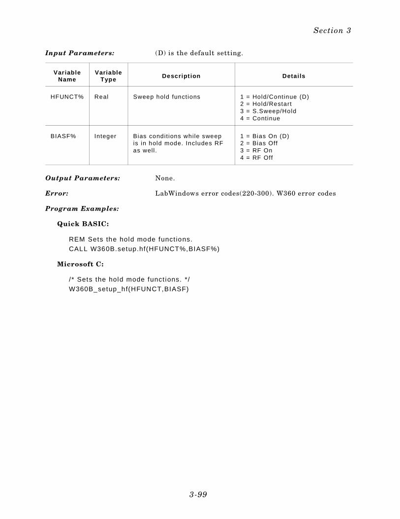
Input Parameters: (D) is the default setting.
Var iableName
VariableType Descript ion Detai ls
HFUNCT% Real Sweep hold functions 1 = Hold/Continue (D)2 = Hold/Restart3 = S.Sweep/Hold4 = Continue
BIASF% Integer Bias condit ions whi le sweepis in hold mode. Includes RFas wel l .
1 = Bias On (D)2 = Bias Off3 = RF On4 = RF Off
Output Parameters: None.
Error: LabWindows error codes(220-300). W360 error codes
Program Examples:
Quick BASIC:
REM Sets the hold mode funct ions.
CALL W360B.setup.hf(HFUNCT%,BIASF%)
Microsoft C:
/ * Sets the hold mode funct ions. */
W360B_setup_hf(HFUNCT,BIASF)
Section 3
3-99
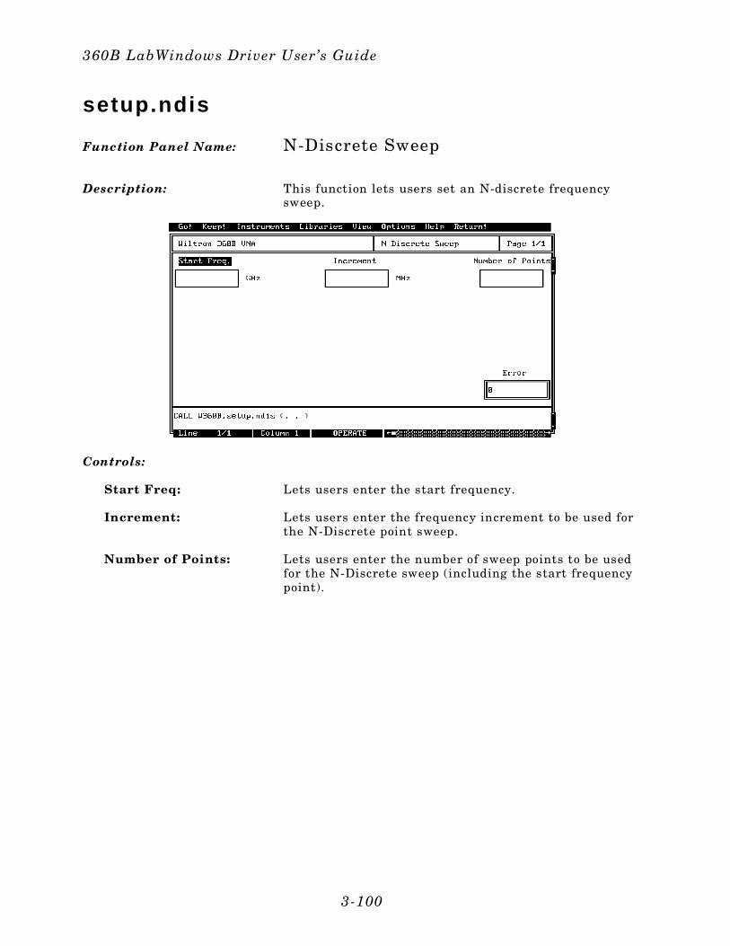
setup.ndis
Function Panel Name: N-Discrete Sweep
Description: This function lets users set an N-discrete frequencysweep.
Controls:
Start Freq: Lets users enter the start frequency.
Increment: Lets users enter the frequency increment to be used forthe N-Discrete point sweep.
Number of Points: Lets users enter the number of sweep points to be usedfor the N-Discrete sweep (including the start frequencypoint).
360B LabWindows Driver User’s Guide
3-100
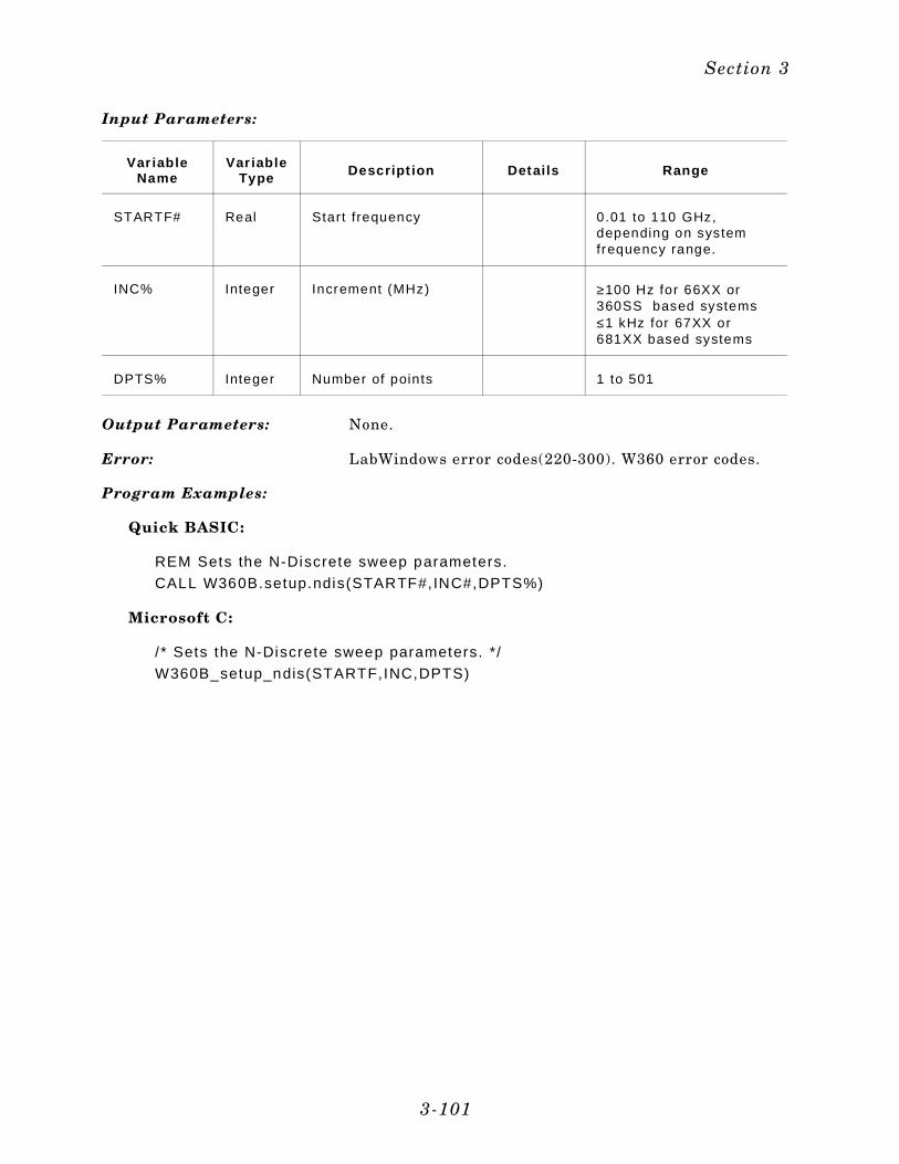
Input Parameters:
Var iableName
Var iableType Descript ion Detai ls Range
STARTF# Real Start frequency 0.01 to 110 GHz,depending on systemfrequency range.
INC% Integer Increment (MHz) ≥100 Hz for 66XX or360SS based systems≤1 kHz for 67XX or681XX based systems
DPTS% Integer Number of points 1 to 501
Output Parameters: None.
Error: LabWindows error codes(220-300). W360 error codes.
Program Examples:
Quick BASIC:
REM Sets the N-Discrete sweep parameters.
CALL W360B.setup.ndis(STARTF#,INC#,DPTS%)
Microsoft C:
/ * Sets the N-Discrete sweep parameters. */
W360B_setup_ndis(STARTF,INC,DPTS)
Section 3
3-101
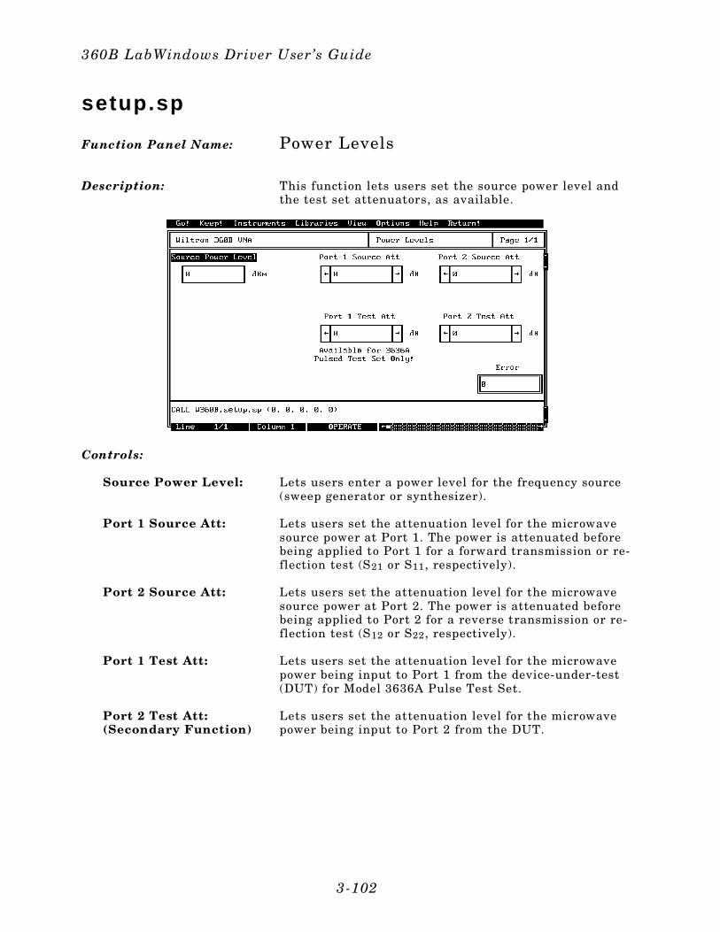
setup.sp
Function Panel Name: Power Levels
Description: This function lets users set the source power level andthe test set attenuators, as available.
Controls:
Source Power Level: Lets users enter a power level for the frequency source(sweep generator or synthesizer).
Port 1 Source Att: Lets users set the attenuation level for the microwavesource power at Port 1. The power is attenuated beforebeing applied to Port 1 for a forward transmission or re-flection test (S21 or S11, respectively).
Port 2 Source Att: Lets users set the attenuation level for the microwavesource power at Port 2. The power is attenuated beforebeing applied to Port 2 for a reverse transmission or re-flection test (S12 or S22, respectively).
Port 1 Test Att: Lets users set the attenuation level for the microwavepower being input to Port 1 from the device-under-test(DUT) for Model 3636A Pulse Test Set.
Port 2 Test Att:(Secondary Function)
Lets users set the attenuation level for the microwavepower being input to Port 2 from the DUT.
360B LabWindows Driver User’s Guide
3-102
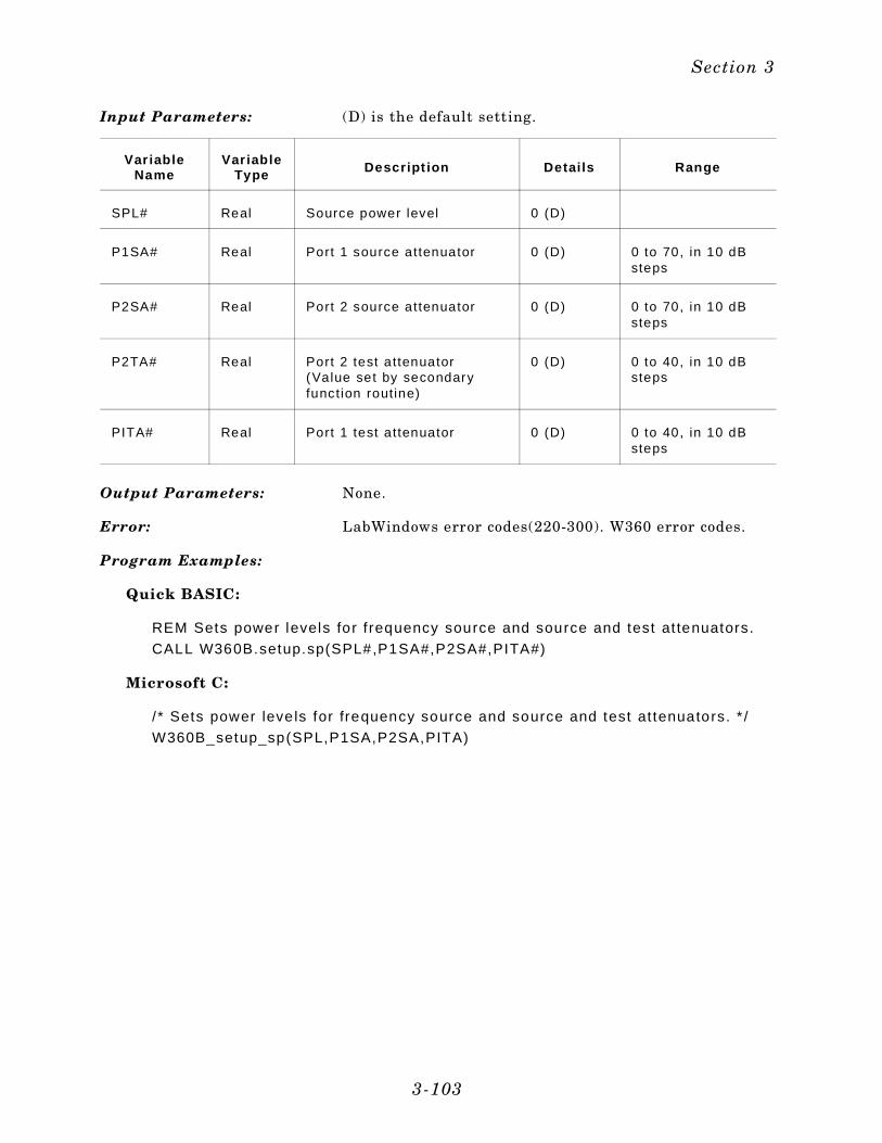
Input Parameters: (D) is the default setting.
Var iableName
Var iableType Descript ion Detai ls Range
SPL# Real Source power level 0 (D)
P1SA# Real Port 1 source attenuator 0 (D) 0 to 70, in 10 dBsteps
P2SA# Real Port 2 source attenuator 0 (D) 0 to 70, in 10 dBsteps
P2TA# Real Port 2 test attenuator(Value set by secondaryfunction routine)
0 (D) 0 to 40, in 10 dBsteps
PITA# Real Port 1 test attenuator 0 (D) 0 to 40, in 10 dBsteps
Output Parameters: None.
Error: LabWindows error codes(220-300). W360 error codes.
Program Examples:
Quick BASIC:
REM Sets power levels for f requency source and source and test at tenuators.
CALL W360B.setup.sp(SPL#,P1SA#,P2SA#,PITA#)
Microsoft C:
/ * Sets power leve ls for frequency source and source and test at tenuators. * /
W360B_setup_sp(SPL,P1SA,P2SA,PITA)
Section 3
3-103
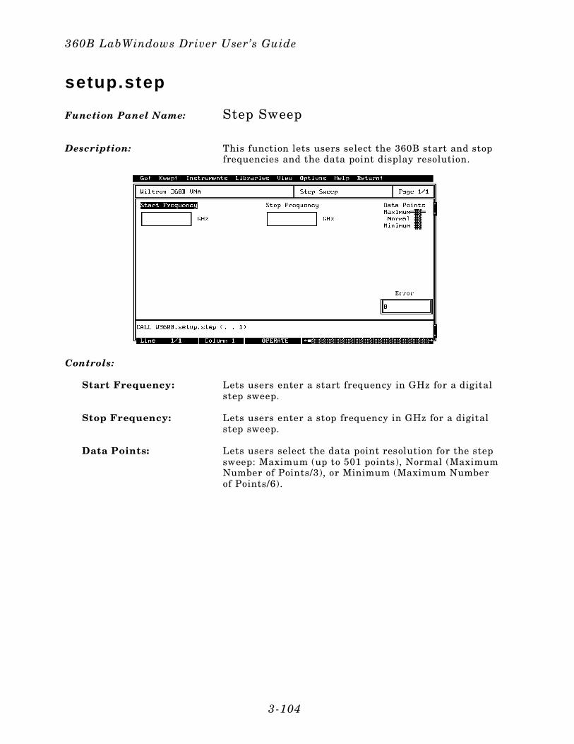
setup.step
Function Panel Name: Step Sweep
Description: This function lets users select the 360B start and stopfrequencies and the data point display resolution.
Controls:
Start Frequency: Lets users enter a start frequency in GHz for a digitalstep sweep.
Stop Frequency: Lets users enter a stop frequency in GHz for a digitalstep sweep.
Data Points: Lets users select the data point resolution for the stepsweep: Maximum (up to 501 points), Normal (MaximumNumber of Points/3), or Minimum (Maximum Numberof Points/6).
360B LabWindows Driver User’s Guide
3-104
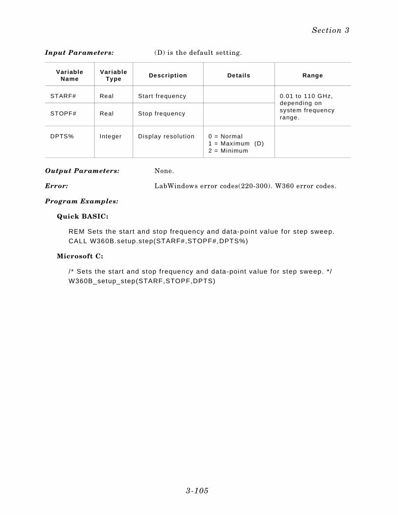
Input Parameters: (D) is the default setting.
Var iableName
Var iableType Descript ion Detai ls Range
STARF# Real Start frequency 0.01 to 110 GHz,depending onsystem frequencyrange.
STOPF# Real Stop frequency
DPTS% Integer Display resolut ion 0 = Normal 1 = Maximum (D)2 = Minimum
Output Parameters: None.
Error: LabWindows error codes(220-300). W360 error codes.
Program Examples:
Quick BASIC:
REM Sets the start and stop frequency and data-point value for step sweep.
CALL W360B.setup.step(STARF#,STOPF#,DPTS%)
Microsoft C:
/ * Sets the start and stop f requency and data-point va lue for step sweep. */
W360B_setup_step(STARF,STOPF,DPTS)
Section 3
3-105
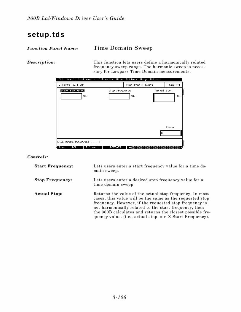
setup.tds
Function Panel Name: Time Domain Sweep
Description: This function lets users define a harmonically relatedfrequency sweep range. The harmonic sweep is neces-sary for Lowpass Time Domain measurements.
Controls:
Start Frequency: Lets users enter a start frequency value for a time do-main sweep.
Stop Frequency: Lets users enter a desired stop frequency value for atime domain sweep.
Actual Stop: Returns the value of the actual stop frequency. In mostcases, this value will be the same as the requested stopfrequency. However, if the requested stop frequency isnot harmonically related to the start frequency, thenthe 360B calculates and returns the closest possible fre-quency value. (i.e., actual stop = n X Start Frequency).
360B LabWindows Driver User’s Guide
3-106
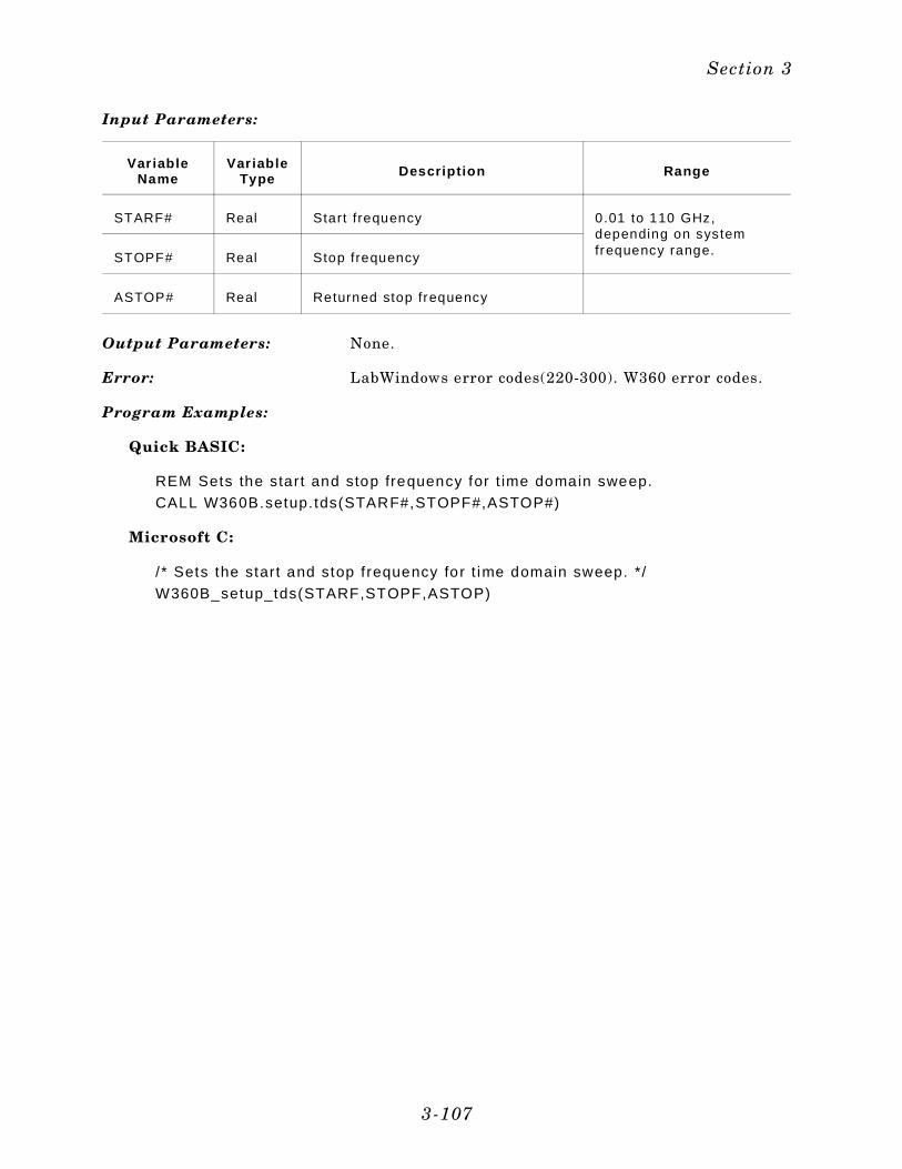
Input Parameters:
Var iableName
Var iableType Descript ion Range
STARF# Real Start frequency 0.01 to 110 GHz,depending on systemfrequency range.STOPF# Real Stop frequency
ASTOP# Real Returned stop frequency
Output Parameters: None.
Error: LabWindows error codes(220-300). W360 error codes.
Program Examples:
Quick BASIC:
REM Sets the start and stop frequency for t ime domain sweep.
CALL W360B.setup. tds(STARF#,STOPF#,ASTOP#)
Microsoft C:
/ * Sets the start and stop f requency for t ime domain sweep. */
W360B_setup_tds(STARF,STOPF,ASTOP)
Section 3
3-107
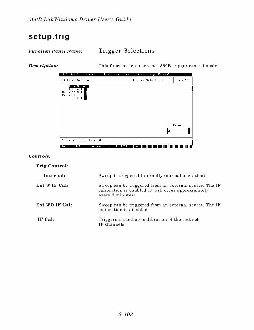
setup.t r ig
Function Panel Name: Trigger Selections
Description: This function lets users set 360B trigger control mode.
Controls:
Trig Control:
Internal: Sweep is triggered internally (normal operation).
Ext W IF Cal: Sweep can be triggered from an external source. The IFcalibration is enabled (it will occur approximatelyevery 3 minutes).
Ext WO IF Cal: Sweep can be triggered from an external source. The IFcalibration is disabled.
IF Cal: Triggers immediate calibration of the test set IF channels.
360B LabWindows Driver User’s Guide
3-108
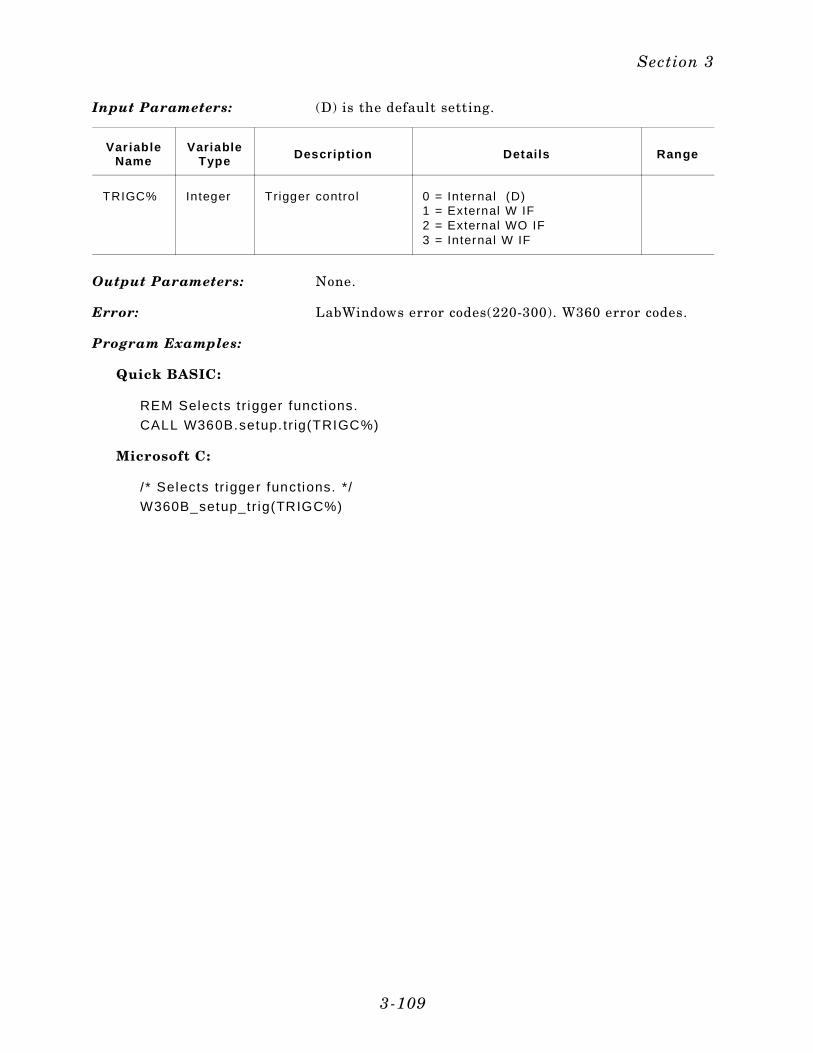
Input Parameters: (D) is the default setting.
Var iableName
VariableType Descript ion Detai ls Range
TRIGC% Integer Trigger control 0 = Internal (D)1 = External W IF2 = External WO IF3 = Internal W IF
Output Parameters: None.
Error: LabWindows error codes(220-300). W360 error codes.
Program Examples:
Quick BASIC:
REM Selects t r igger funct ions.
CALL W360B.setup. t r ig(TRIGC%)
Microsoft C:
/ * Selects tr igger functions. */
W360B_setup_tr ig(TRIGC%)
Section 3
3-109
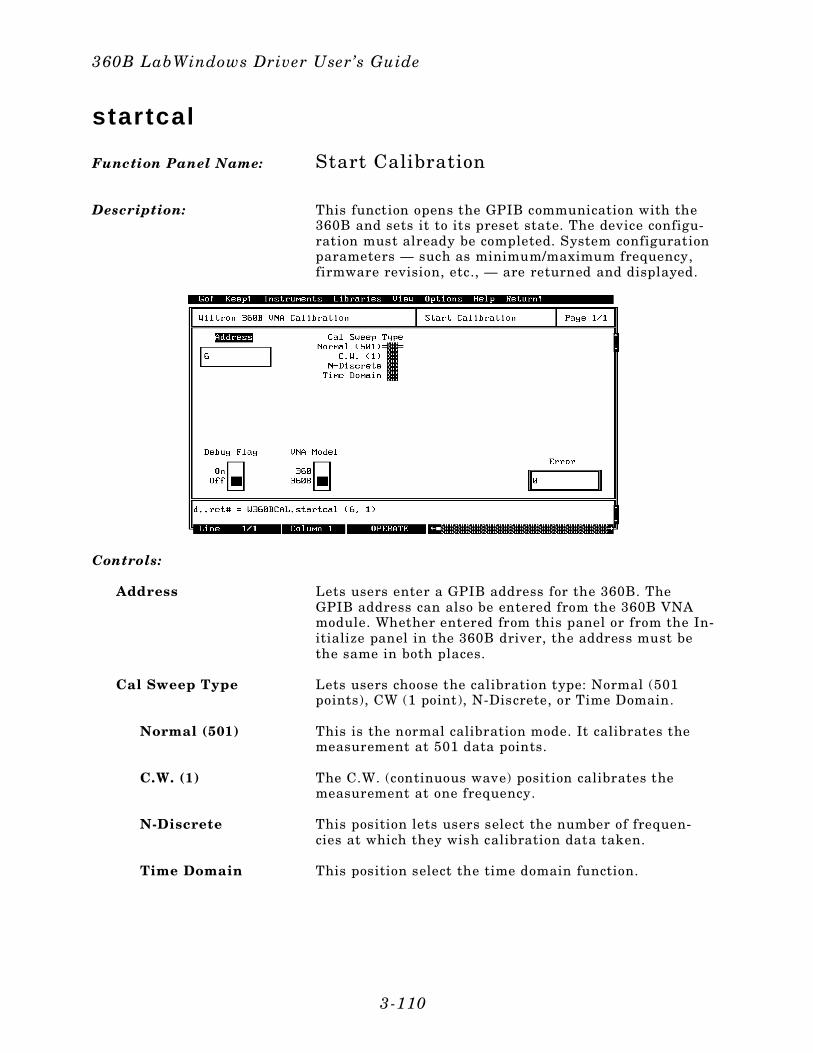
star tcal
Function Panel Name: Start Calibration
Description: This function opens the GPIB communication with the360B and sets it to its preset state. The device configu-ration must already be completed. System configurationparameters — such as minimum/maximum frequency,firmware revision, etc., — are returned and displayed.
Controls:
Address Lets users enter a GPIB address for the 360B. TheGPIB address can also be entered from the 360B VNAmodule. Whether entered from this panel or from the In-itialize panel in the 360B driver, the address must bethe same in both places.
Cal Sweep Type Lets users choose the calibration type: Normal (501points), CW (1 point), N-Discrete, or Time Domain.
Normal (501) This is the normal calibration mode. It calibrates themeasurement at 501 data points.
C.W. (1) The C.W. (continuous wave) position calibrates themeasurement at one frequency.
N-Discrete This position lets users select the number of frequen-cies at which they wish calibration data taken.
Time Domain This position select the time domain function.
360B LabWindows Driver User’s Guide
3-110
Debug Flag:(Secondary Function)
Controls the Debug Function. This function is dis-cussed in Section 2.
Off: Debug Function is off.
On: All appropriate W360B errors will be returned, refer topage 2-8.
VNA Model:(Secondary Function)
Lets users select Model 360 or Model 360B, dependingon which model they will be using.
Input Parameters: (D) is the default setting.
Var iableName
Var iableType Descript ion Detai ls
ADD% Integer VNA Address.
SWEEPTYPE%
Integer VNA cal ibrat ionsweep type
1 = Normal (501 pts) - step sweep2 = CW Sweep (1 pt)3 = N-Discrete sweep4 = Time Domain (Harmonic) sweep
Output Parameters: None.
Error: LabWindows error codes(220-300). W360B error codes.
Program Examples:
QuickBASIC:
REM Assign GPIB address.
d. . ret# = W360BCAL.startca l (ADD%, SWEEP TYPE%)
Microsoft C:
/ * Assign GPIB address. * /
d_ret = W360BCAL_startca l (ADD,SWEEP TYPE)
Section 3
3-111
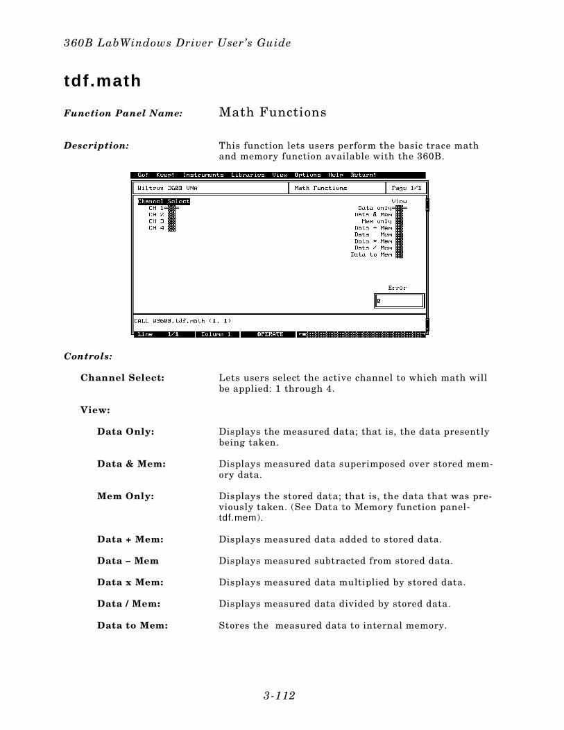
tdf .math
Function Panel Name: Math Functions
Description: This function lets users perform the basic trace mathand memory function available with the 360B.
Controls:
Channel Select: Lets users select the active channel to which math willbe applied: 1 through 4.
View:
Data Only: Displays the measured data; that is, the data presentlybeing taken.
Data & Mem: Displays measured data superimposed over stored mem-ory data.
Mem Only: Displays the stored data; that is, the data that was pre-viously taken. (See Data to Memory function panel-tdf.mem).
Data + Mem: Displays measured data added to stored data.
Data – Mem Displays measured subtracted from stored data.
Data x Mem: Displays measured data multiplied by stored data.
Data / Mem: Displays measured data divided by stored data.
Data to Mem: Stores the measured data to internal memory.
360B LabWindows Driver User’s Guide
3-112
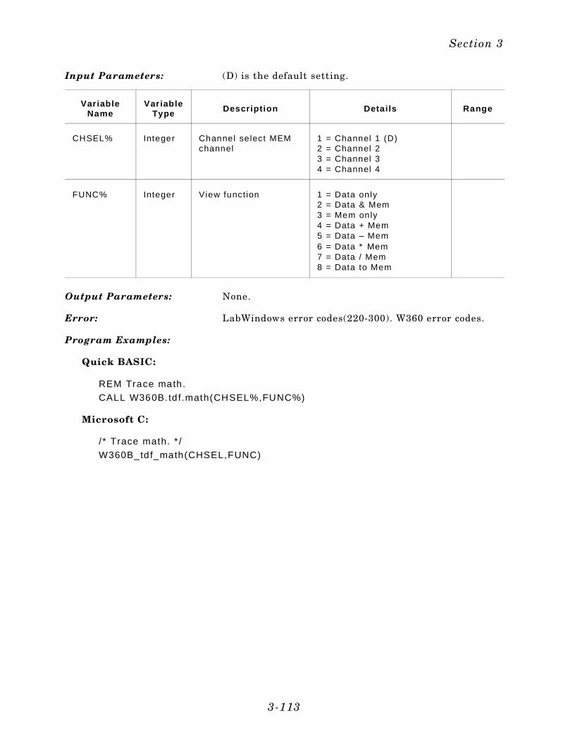
Input Parameters: (D) is the default setting.
Var iableName
Var iableType Descript ion Detai ls Range
CHSEL% Integer Channel select MEMchannel
1 = Channel 1 (D)2 = Channel 23 = Channel 34 = Channel 4
FUNC% Integer View function 1 = Data only2 = Data & Mem3 = Mem only4 = Data + Mem 5 = Data – Mem6 = Data ∗ Mem7 = Data / Mem8 = Data to Mem
Output Parameters: None.
Error: LabWindows error codes(220-300). W360 error codes.
Program Examples:
Quick BASIC:
REM Trace math.
CALL W360B.td f.math(CHSEL%,FUNC%)
Microsoft C:
/ * Trace math. * /
W360B_tdf_math(CHSEL,FUNC)
Section 3
3-113
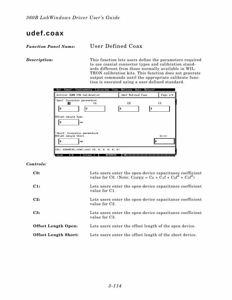
udef.coax
Function Panel Name: User Defined Coax
Description: This function lets users define the parameters requiredto use coaxial connector types and calibration stand-ards different from those normally available in WIL-TRON calibration kits. This function does not generateoutput commands until the appropriate calibrate func-tion is executed using a user-defined standard.
Controls:
C0: Lets users enter the open-device capacitance coefficientvalue for C0. (Note: COPEN = C0 + C1f + C2f2 + C3f3)
C1: Lets users enter the open-device capacitance coefficientvalue for C1.
C2: Lets users enter the open-device capacitance coefficientvalue for C2.
C3: Lets users enter the open-device capacitance coefficientvalue for C3.
Offset Length Open: Lets users enter the offset length of the open device.
Offset Length Short: Lets users enter the offset length of the short device.
360B LabWindows Driver User’s Guide
3-114
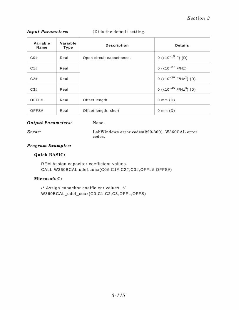
Input Parameters: (D) is the default setting.
Var iableName
Var iableType Descript ion Detai ls
C0# Real Open circuit capacitance. 0 (x10–15 F) (D)
C1# Real 0 (x10–27 F/Hz)
C2# Real 0 (x10–36 F/Hz2) (D)
C3# Real 0 (x10–45 F/Hz3) (D)
OFFL# Real Offset length 0 mm (D)
OFFS# Real Offset length, short 0 mm (D)
Output Parameters: None.
Error: LabWindows error codes(220-300). W360CAL errorcodes.
Program Examples:
Quick BASIC:
REM Assign capaci tor coef f icient values.
CALL W360BCAL.udef.coax(C0#,C1#,C2#,C3#,OFFL#,OFFS#)
Microsoft C:
/ * Assign capacitor coef f ic ient values. */
W360BCAL_udef_coax(C0,C1,C2,C3,OFFL,OFFS)
Section 3
3-115
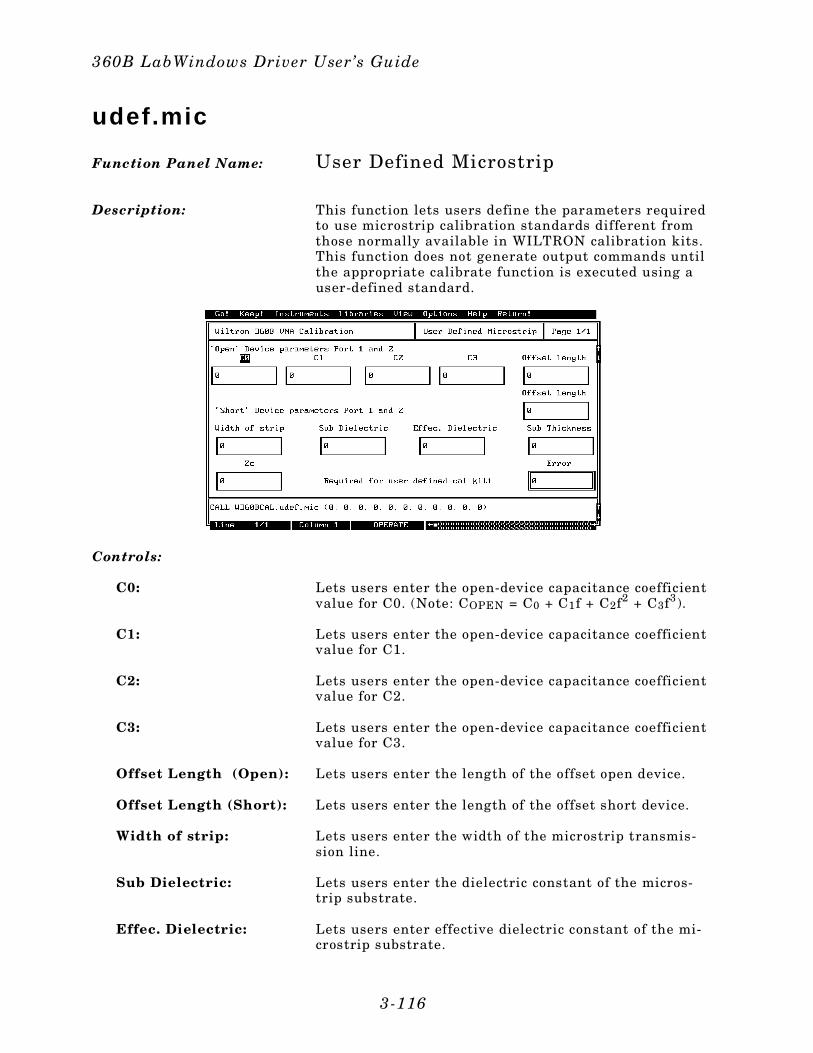
udef.mic
Function Panel Name: User Defined Microstrip
Description: This function lets users define the parameters requiredto use microstrip calibration standards different fromthose normally available in WILTRON calibration kits.This function does not generate output commands untilthe appropriate calibrate function is executed using auser-defined standard.
Controls:
C0: Lets users enter the open-device capacitance coefficientvalue for C0. (Note: COPEN = C0 + C1f + C2f2 + C3f3).
C1: Lets users enter the open-device capacitance coefficientvalue for C1.
C2: Lets users enter the open-device capacitance coefficientvalue for C2.
C3: Lets users enter the open-device capacitance coefficientvalue for C3.
Offset Length (Open): Lets users enter the length of the offset open device.
Offset Length (Short): Lets users enter the length of the offset short device.
Width of strip: Lets users enter the width of the microstrip transmis-sion line.
Sub Dielectric: Lets users enter the dielectric constant of the micros-trip substrate.
Effec. Dielectric: Lets users enter effective dielectric constant of the mi-crostrip substrate.
360B LabWindows Driver User’s Guide
3-116
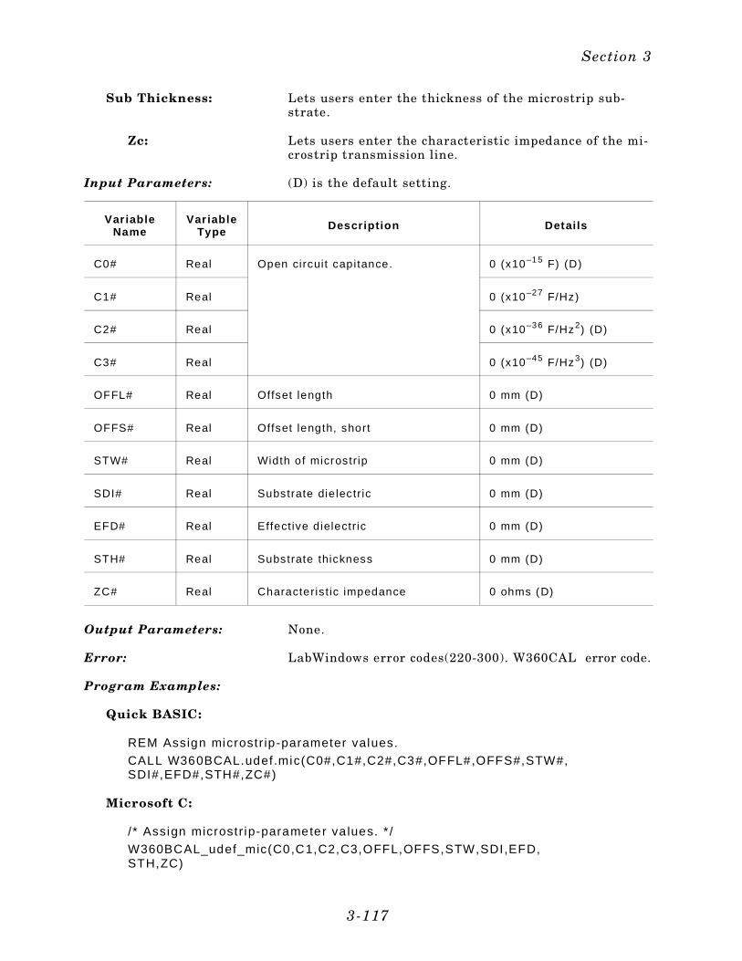
Sub Thickness: Lets users enter the thickness of the microstrip sub-strate.
Zc: Lets users enter the characteristic impedance of the mi-crostrip transmission line.
Input Parameters: (D) is the default setting.
Var iableName
Var iableType Descript ion Detai ls
C0# Real Open circuit capitance. 0 (x10–15 F) (D)
C1# Real 0 (x10–27 F/Hz)
C2# Real 0 (x10–36 F/Hz2) (D)
C3# Real 0 (x10–45 F/Hz3) (D)
OFFL# Real Offset length 0 mm (D)
OFFS# Real Offset length, short 0 mm (D)
STW# Real Width of microstr ip 0 mm (D)
SDI# Real Substrate die lectr ic 0 mm (D)
EFD# Real Effect ive dielectr ic 0 mm (D)
STH# Real Substrate thickness 0 mm (D)
ZC# Real Characteris t ic impedance 0 ohms (D)
Output Parameters: None.
Error: LabWindows error codes(220-300). W360CAL error code.
Program Examples:
Quick BASIC:
REM Assign microstr ip-parameter values.
CALL W360BCAL.udef.mic(C0#,C1#,C2#,C3#,OFFL#,OFFS#,STW#,SDI#,EFD#,STH#,ZC#)
Microsoft C:
/ * Assign microstr ip-parameter va lues. * /
W360BCAL_udef_mic(C0,C1,C2,C3,OFFL,OFFS,STW,SDI,EFD,STH,ZC)
Section 3
3-117
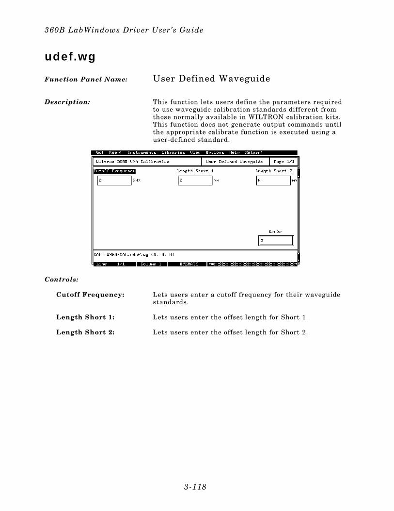
udef.wg
Function Panel Name: User Defined Waveguide
Description: This function lets users define the parameters requiredto use waveguide calibration standards different fromthose normally available in WILTRON calibration kits.This function does not generate output commands untilthe appropriate calibrate function is executed using auser-defined standard.
Controls:
Cutoff Frequency: Lets users enter a cutoff frequency for their waveguidestandards.
Length Short 1: Lets users enter the offset length for Short 1.
Length Short 2: Lets users enter the offset length for Short 2.
360B LabWindows Driver User’s Guide
3-118
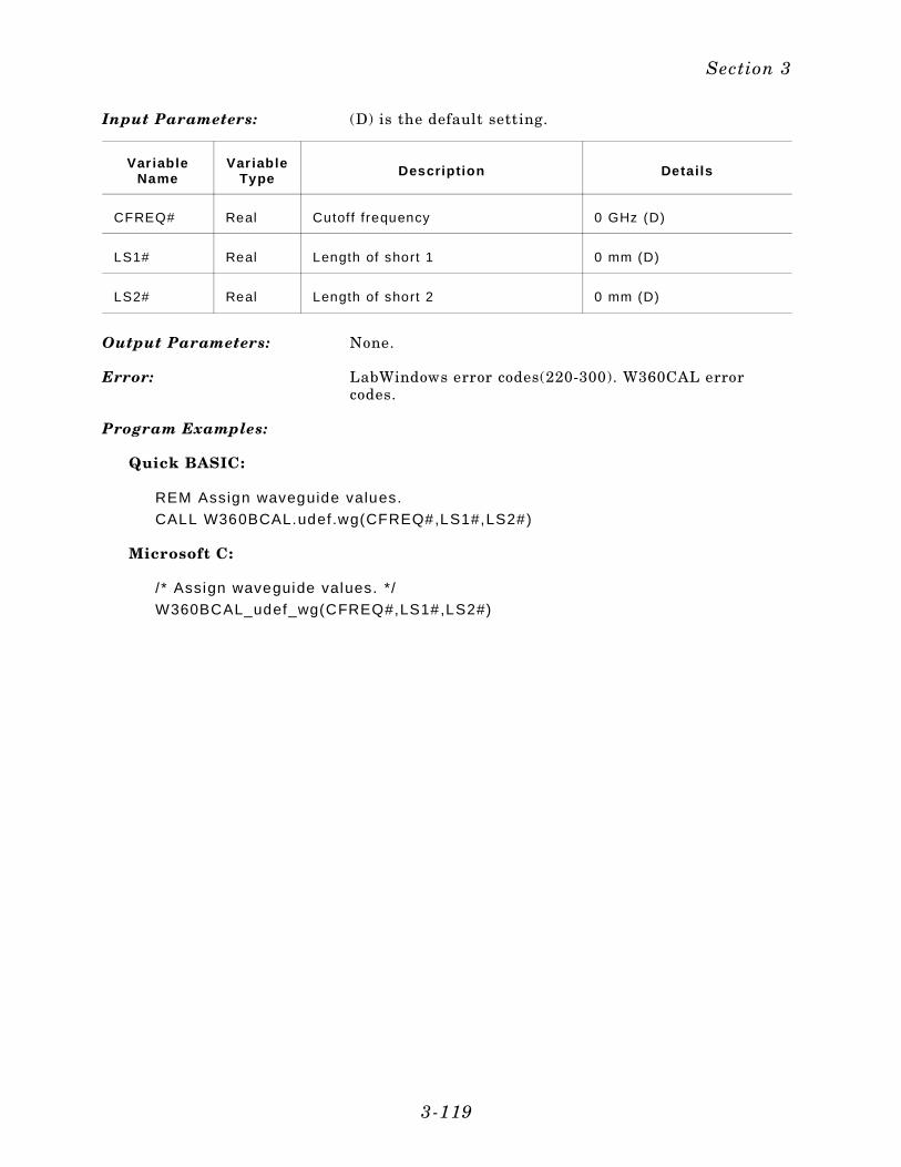
Input Parameters: (D) is the default setting.
Var iableName
Var iableType Descript ion Detai ls
CFREQ# Real Cutoff frequency 0 GHz (D)
LS1# Real Length of short 1 0 mm (D)
LS2# Real Length of short 2 0 mm (D)
Output Parameters: None.
Error: LabWindows error codes(220-300). W360CAL errorcodes.
Program Examples:
Quick BASIC:
REM Assign waveguide values.
CALL W360BCAL.udef.wg(CFREQ#,LS1#,LS2#)
Microsoft C:
/ * Assign waveguide values. */
W360BCAL_udef_wg(CFREQ#,LS1#,LS2#)
Section 3
3-119
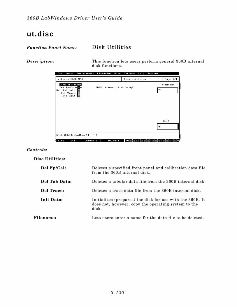
ut.disc
Function Panel Name: Disk Utilities
Description: This function lets users perform general 360B internaldisk functions.
Controls:
Disc Utilities:
Del Fp/Cal: Deletes a specified front panel and calibration data filefrom the 360B internal disk.
Del Tab Data: Deletes a tabular data file from the 360B internal disk.
Del Trace: Deletes a trace data file from the 360B internal disk.
Init Data: Initializes (prepares) the disk for use with the 360B. Itdoes not, however, copy the operating system to thedisk.
Filename: Lets users enter a name for the data file to be deleted.
360B LabWindows Driver User’s Guide
3-120

Input Parameters: (D) is the default setting.
VariableName
VariableType Descript ion Detai ls
DISCUT% Integer Disk function 1 = Delete Cal and front panel (D) 2 = Delete trace 3 = Delete tabular data 6 = Ini t ia l ize Data
FAME$ String Fi lename 8 characters, maximum
Output Parameters: None.
Error: LabWindows error codes(220-300). W360 error codes.
Program Examples:
Quick BASIC:
REM Selects 360B f loppy disk funct ion.
CALL W360B.ut .d isc(DISCUT%,FAME$)
Microsoft C:
/ *Selects 360B f loppy disk function. */
W360B_ut_disc(DISCUT,FAME)
Section 3
3-121

ut.video
Function Panel Name: Video Configuration
Description: This function lets users set the system video configura-tion switches.
Controls:
Connect Int. Screen
360 Video: Connects internal screen to the internal 360B video sig-nal (default).
VGA In: Connects internal screen to the signal present at theVGA IN rear panel connector.
Connect VGA Out:
360 Video: Connects 360 video signal to rear panel VGA OUT con-nector (default).
VGA In: Connects signal on rear panel VGA IN connector to rearpanel VGA OUT connector.
360B LabWindows Driver User’s Guide
3-122
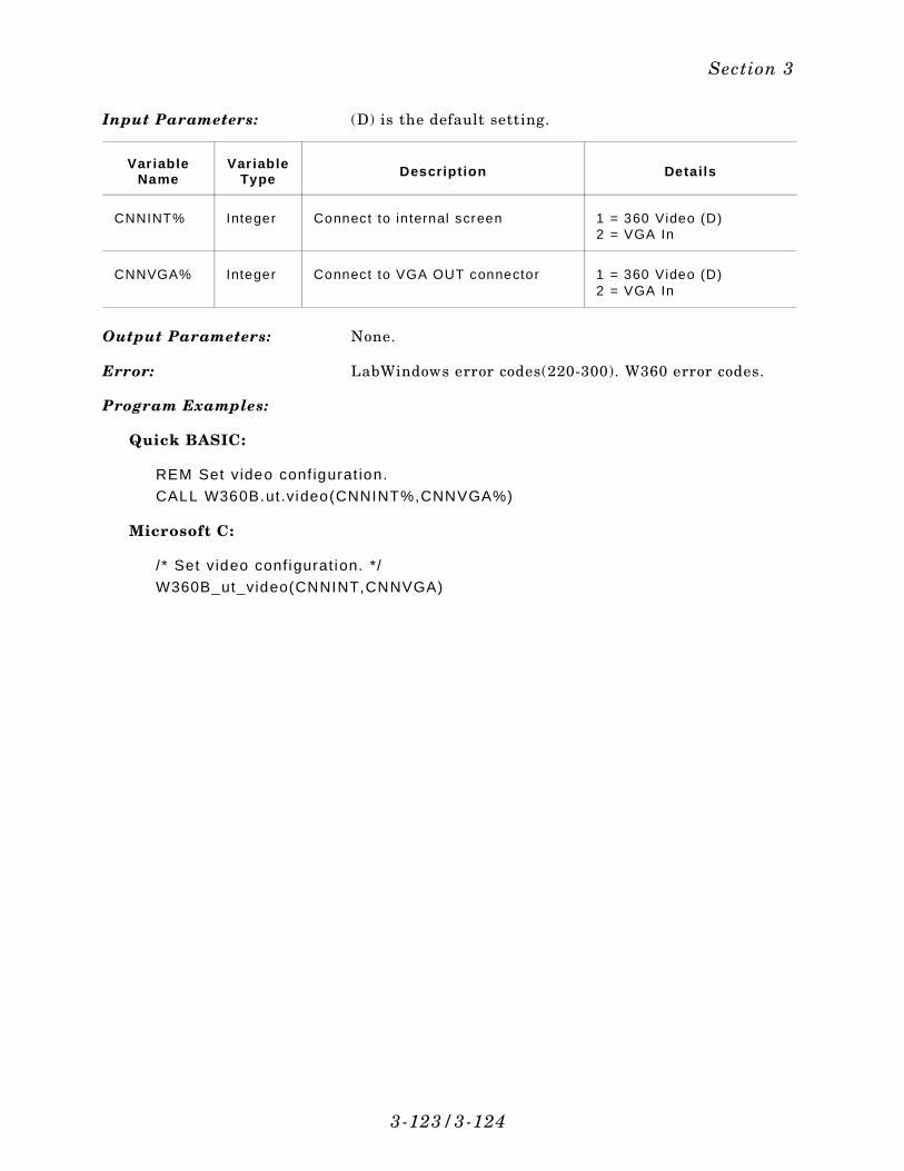
Input Parameters: (D) is the default setting.
Var iableName
Var iableType Descript ion Detai ls
CNNINT% Integer Connect to internal screen 1 = 360 Video (D)2 = VGA In
CNNVGA% Integer Connect to VGA OUT connector 1 = 360 Video (D)2 = VGA In
Output Parameters: None.
Error: LabWindows error codes(220-300). W360 error codes.
Program Examples:
Quick BASIC:
REM Set video conf igurat ion.
CALL W360B.ut .video(CNNINT%,CNNVGA%)
Microsoft C:
/ * Set video conf igurat ion. */
W360B_ut_video(CNNINT,CNNVGA)
3-123/3-124
Section 3

SubjectIndex
A
AC% . . . . . . . . . . . . . . . . . . . . . 3-77ACOEF# . . . . . . 3-48, 3-52, 3-55, 3-58, 3-62Active channel . . . . . . 3-17, 3-25, 3-72, 3-77, . . . . . . . . . . . . . . . . . 3-79, 3-83, 3-85ADD% . . . . . . . . . . . . . . . . 3-33, 3-111ASTOP# . . . . . . . . . . . . . . . . . . 3-107Autoscale . . . . . . . . . . . . . . . . . . 3-77Averaging Factor . . . . . . . 2-30, 3-68 - 3-69Averaging on/off . . . . . . . . . . . . . . . 3-69AVG% . . . . . . . . . . . . . . . . . . . . 3-69AVON% . . . . . . . . . . . . . . . . . . . 3-69
B
BASIC . . . . . . . . . . . . . . . . . 1-4, 2-25BCOEF# . . . . . . 3-48, 3-52, 3-55, 3-58, 3-62BIASF% . . . . . . . . . . . . . . . . . . . 3-99BKPT# . . . . . . . . . . . . . 3-36, 3-40, 3-44Blank display . . . . . . . . . . . . . . . . 3-95Blank Frequencies . . . . . . 2-39, 3-94 - 3-95Breakpoint frequency . . . . . 3-36, 3-40, 3-44BW% . . . . . . . . . . . . . . . . . . . . . 3-91
C
C . . . . . . . . . . . . . . . . . . . . 1-4, 2-25C0# . . . . . . . . . . . . . . . . . 3-115, 3-117C1# . . . . . . . . . . . . . . . . . 3-115, 3-117C2# . . . . . . . . . . . . . . . . . 3-115, 3-117C3# . . . . . . . . . . . . . . . . . 3-115, 3-117CAKIT% . . . . . . . . . . . . . . . . . . . 3-62cal.load . . . . . . . . . . . . . . . . . 2-32, 3-8cal.pwr . . . . . . . . . . . . . . . . . 2-32, 3-10Calibration Class . . . . . . . . . . . . . . 2-31Calibration kit . . . . . . . . . . . . . . . . 3-62Calibration step . . . . . . . . . . . . . . . 3-15Calibration types . 3-48, 3-52, 3-55, 3-58, 3-62CALT% . . . . . . . 3-48, 3-52, 3-55, 3-58, 3-62Cartesian Scale . . . . . . . . . . . . 2-34, 3-76CCOEF# . . . . . . 3-48, 3-52, 3-55, 3-58, 3-62CFREQ# . . . . . . . . . . . . . . . . . . 3-119Channel Definition . . . . . . . . . . 2-34, 3-70Channel Display Mode . . . . . . . . 2-34, 3-92Channel select MEM channel . . . . . . 3-113Characteristic impedance . . . . . . . . . 3-117CHD% . . . . . . . . . . . . . . . . . . . . 3-93CHSEL% . . . . . . 3-17, 3-23, 3-25, 3-72, 3-77, . . . . . . . . . . . . . . 3-79, 3-83, 3-85, 3-113Close . . . . . . . . . . . . . . . . . . 2-40, 3-12CNNINT% . . . . . . . . . . . . . . . . . 3-123CNNVGA% . . . . . . . . . . . . . . . . 3-123
Connect to internal screen . . . . . . . . 3-123Connect to VGA OUT connector . . . . . . 3-123Creating a Compiled Program . . . . . . 2-25cs.meas . . . . . . . . . . . . . . . . 2-32, 3-14CSTP% . . . . . . . . . . . . . . . . . . . 3-15Cutoff frequency . . . . . . . . . . . . . . 3-119CW Frequency . . . . . . . . . . . . . . . 3-97CW Sweep . . . . . . . . . . . . . . 2-30, 3-96
D
D1L# . . . . . . . . . . . . . . 3-36, 3-40, 3-44D2LM# . . . . . . . . . . . . . 3-36, 3-40, 3-44D3LM# . . . . . . . . . . . . . 3-36, 3-40, 3-44da.lim . . . . . . . . . . . . . . . . . 2-36, 3-16Data Analysis Class . . . . . . . . . . . . 2-35Data I/O Class . . . . . . . . . . . . . . . 2-37Data trace . . . . . . . . . . . . . . . . . 3-27Data type: corrected or final . . . . . . . . 3-23Date . . . . . . . . . . . . . . . . . . . . 3-31DCRES% . . . . . . . . . . . . . . . . . . 3-85DCVALUE# . . . . . . . . . . . . . . . . 3-85debug flag . . . . . . . . . . . . . . . . . 2-12debug switch . . . . . . . . . . . . . . . . . 2-9Debug Utility . . . . . . . . . . . . . . 2-7, 2-9Delay aperature . . . . . . . . . . . . . . 3-77DEN% . . . . . . . . . . . . . . . . . . . 3-72Denominator . . . . . . . . . . . . . . . . 3-72Device ID . . . . . . . . . . . . . . . . . . 3-31DID$ . . . . . . . . . . . . . . . . . . . . 3-31dio.itd . . . . . . . . . . . . . . . . . 2-38, 3-18dio.otd . . . . . . . . . . . . . . . . 2-38, 3-22DISCUT% . . . . . . . . . . . . . . . . . 3-121Disk function . . . . . . . . . . . . . . . . 3-121Disk Functions . . . . . . . . . . . . . . . 2-37Disk Utilities . . . . . . . . . . . . . 2-38, 3-120Display limit lines . . . . . . . . . . . . . 3-17Display resolution . . . . . . . . . . . . . 3-105Display Setup Class . . . . . . . . . . . . 2-34DLM% . . . . . . . . . . . . . . . . . . . 3-17DOM% . . . . . . . . . . . . . . . . . . . 3-85Domain Selection . . . . . . . . . . 2-36, 3-84DPTS% . . . . . . . . . 3-11, 3-97, 3-101, 3-105DT$ . . . . . . . . . . . . . . . . . . . . . 3-31DTR% . . . . . . . . . . . . . . . . . . . 3-27DTYPE# . . . . . . . . . . . . . . . . . . 3-23Dual limit display . . . . . . . . . . . . . 3-17DUALL% . . . . . . . . . . . . . . . . . . 3-17
E
EFD# . . . . . . . . . . . . . . . . . . . . 3-117Effective dielectric . . . . . . . . . . . . . 3-117
Index 3
error messages . . . . . . . . . . . . . . . 2-10executable (file) . . . . . . . . . . . . . . . 2-4
F
FAME$ . . . . . . . . . . . . . 3-65, 3-67, 3-121FAME% . . . . . . . . . . . . . . . . 3-19, 3-23FBL% . . . . . . . . . . . . . . . . . . . . 3-95File name to recall . . . . . . . . . . 3-65, 3-67Filename . . . . . . . . . . . . 3-19, 3-23, 3-121Flat power cal on/off . . . . . . . . . . . . 3-11Flat Power Calibration . . . . . . . . 2-32, 3-10FREQ# . . . . . . . . . . . . . . . . . . . . 3-97FUNC% . . . . . . . . . . . . . . . 3-83, 3-113Function Panel Structure . . . . . . . . . . 3-3
G
Gate center time/distance . . . . . . . . . . 3-87Gate shape . . . . . . . . . . . . . . . . . . 3-87Gate span time/distance . . . . . . . . . . 3-87Gate start time/distance . . . . . . . . . . 3-87Gate stop time/distance . . . . . . . . . . . 3-87Gated measurements . . . . . . . . . . . . 3-87GCENT# . . . . . . . . . . . . . . . . . . . 3-87GD# . . . . . . . . . . . . . . . . . . . . . 3-77General . . . . . . . . . . . . . . . . . 1-3, 2-4get.mark . . . . . . . . . . . . . . . . 2-36, 3-24Global and Local Variables . . . . . . . . . 3-3GMEAS% . . . . . . . . . . . . . . . . . . 3-87Graph type . . . . . . . . . . . . . . . . . . 3-72Graph type: polar or Smith Chart . . . . . 3-79GRAT% . . . . . . . . . . . . . . . . . . . 3-27Graticule . . . . . . . . . . . . . . . . . . . 3-27GSH% . . . . . . . . . . . . . . . . . . . . 3-87GSPAN# . . . . . . . . . . . . . . . . . . . 3-87GSTART# . . . . . . . . . . . . . . . . . . 3-87GSTOP# . . . . . . . . . . . . . . . . . . . 3-87GT% . . . . . . . . . . . . . . . . . . . . . 3-72
H
Hardcopy . . . . . . . . . . . . . . . . . . 2-38hc.plot . . . . . . . . . . . . . . . . . . . . 3-26hc.plt . . . . . . . . . . . . . . . . . . . . . 2-38hc.prnt . . . . . . . . . . . . . . . . . 2-38, 3-28hc.ui . . . . . . . . . . . . . . . . . . 2-38, 3-30HDR% . . . . . . . . . . . . . . . . . . . . 3-27Header Labels . . . . . . . . . . . . . 2-38, 3-30Headere . . . . . . . . . . . . . . . . . . . 3-27HFUNCT% . . . . . . . . . . . . . . . . . 3-99Hold Functions . . . . . . . . . . . . 2-30, 3-98Housekeeping Functions . . . . . . . . . . 2-40
I
INC% . . . . . . . . . . . . . . . . . . . . 3-101Increment (MHz) . . . . . . . . . . . . . . 3-101init . . . . . . . . . . . . . . . . . . 2-40, 3-32Initialize . . . . . . . . . . . . . . . 2-40, 3-32Input Trace Data . . . . . . . . . . . 2-38, 3-18Installing Instrument Drivers . . . . . . . 1-4Introduction . . . . . . . . . . . . . . . 2-3, 3-3ISO% . . . . . . . 3-36, 3-40, 3-44, 3-48, 3-52, . . . . . . . . . . . . . . . . . 3-55, 3-58, 3-62
Isolation . . . . . 3-36, 3-40, 3-44, 3-48, 3-52, . . . . . . . . . . . . . . . . . 3-55, 3-58, 3-62
L
LabWindows libraries . . . . . . . . . . . . 1-4Length coefficient of non-zero thruline . . . . . . . . . . . . 3-48, 3-52, 3-55Length of line 1 . . . . . . . . 3-36, 3-40, 3-44Length of line 2 . . . . . . . . 3-36, 3-40, 3-44Length of line 3 . . . . . . . . 3-36, 3-40, 3-44Length of short 1 . . . . . . . . . . . . . . 3-119Length of short 2 . . . . . . . . . . . . . . 3-119libraries . . . . . . . . . . . . . . . . . . . 1-4Limit Functions . . . . . . . . . . . . . . 2-35Line or match . . . . . . . . . 3-36, 3-40, 3-44Line type . . . . . . . . . . . . 3-36, 3-40, 3-44LL# . . . . . . . . . . . . . . . . . . . . . 3-17LL2# . . . . . . . . . . . . . . . . . . . . 3-17LM% . . . . . . . . . . . . . . 3-36, 3-40, 3-44load (file) . . . . . . . . . . . . . . . . . . . 2-5Load Cal Kit Coeff . . . . . . . . . . . . . 2-32Load Cal Kit Coeff(icients) . . . . . . . . . 3-8Load calibration from disk . . . . . . . . . 3-9load files . . . . . . . . . . . . . . . . . . . 2-4Load type . . . . . . . . . . . . 3-48, 3-55, 3-58Loading 67XX Driver as Instrument Module 2-5Loss Coefficient . . . . . . . . . . . 3-58, 3-62Lower limit . . . . . . . . . . . . . . . . . 3-17lrl.line . . . . . . . . . . 2-32, 3-34, 3-38, 3-42LRL/LRM . . . . . . . . . . . . . . . . . . 2-32LRL/LRM Coax . . . . . . . . . . . . . . 3-34LRL/LRM Microstrip . . . . . . . . . . . 3-38LRL/LRM Waveguide . . . . . . . . . . . 3-42LRLREFPL% . . . . . . . . . 3-36, 3-40, 3-44LS1# . . . . . . . . . . . . . . . . . . . . 3-119LS2# . . . . . . . . . . . . . . . . . . . . 3-119LT% . . . . . . . . . . . . . . . 3-36, 3-40, 3-44LTD% . . . . . . . . . . . . . . 3-48, 3-55, 3-58LWMAKE . . . . . . . . . . . . . . . . . 2-25
360B LabWindows Driver User’s Guide
Index 4
M
Marker amplitude value . . . . . . . . . . 3-83Marker frequency . . . . . . . . . . . 3-75, 3-83Marker function . . . . . . . . . . . . . . . 3-83Marker Functions . . . . . . . . . . . . . . 2-35Marker imaginary value . . . . . . . . . . 3-83Marker selected . . . . . . . . . . . . . . . 3-83Marker x on/off . . . . . . . . . . . . . . . 3-75Markers . . . . . . . . . . . . . . . . . . . 3-27Math function . . . . . . . . . . . . . . . 3-113Math Functions . . . . . . . . . . . 2-36, 3-112Measure Cal(ibration) Standards . . . . . 3-14Menu . . . . . . . . . . . . . . . . . . . . . 3-27MENU% . . . . . . . . . . . . . . . . . . . 3-27Microsoft C . . . . . . . . . . . . . . 1-4, 2-25MK% . . . . . . . . . . . . . . . . . . . . . 3-83MKFx% . . . . . . . . . . . . . . . . . . . 3-75MKR% . . . . . . . . . . . . . . . . . . . . 3-27MKV# . . . . . . . . . . . . . . . . . . . . 3-83MKV1# thru MKV9# . . . . . . . . . . . . 3-25MKVF# . . . . . . . . . . . . . . . . . . . 3-83MKVI# . . . . . . . . . . . . . . . . . . . . 3-83MKVI1# thru MKVI9# . . . . . . . . . . . 3-25MKx% . . . . . . . . . . . . . . . . . . . . 3-75MNUM$ . . . . . . . . . . . . . . . . . . . 3-31Model number . . . . . . . . . . . . . . . . 3-31
N
N-Discrete Sweep . . . . . . . . . . 2-30, 3-100NUM% . . . . . . . . . . . . . . . . . . . . 3-72NUMB% . . . . . . . . . . . . 3-36, 3-40, 3-44Number of bands . . . . . . . 3-36, 3-40, 3-44Number of points . . . . . . . . . . . . . 3-101Number of points drawn in CW mode . . . 3-97Number of skipped data points . . . . . . . 3-11Number of sweeps to average . . . . . . . . 3-11Numerator . . . . . . . . . . . . . . . . . . 3-72NUMSW% . . . . . . . . . . . . . . . . . . 3-11
O
OFFL# . . . . . . . 3-48, 3-52, 3-55, 3-58, 3-62, . . . . . . . . . . . . . . . . . . . 3-115, 3-117OFFLR# . . . . . . . . . . . . 3-36, 3-40, 3-44OFFS# . . . . . . . . . . . . . . . 3-115, 3-117Offset length . . . 3-48, 3-52, 3-55, 3-115, 3-117Offset length of THRU . . . . . . . . 3-58, 3-62Offset length, short . . . . . . . . 3-115, 3-117Offset-Short . . . . . . . . . . . . . . . . . 2-32Offset-Short Coax . . . . . . . . . . . . . . 3-46Offset-Short Microstrip . . . . . . . . . . . 3-50
Offset-Short Waveguide . . . . . . . . . . 3-54ONF% . . . . . . . . . . . . . . . . . . . 3-11Open circuit capacitance . . . . . 3-115, 3-117Open-Short-Load . . . . . . . . . . . . . 2-32Open-Short-Load Coax . . . . . . . . . . 3-56Open-Short-Load Microstrip . . . . . . . 3-60Operator name . . . . . . . . . . . . . . . 3-31OPNAME$ . . . . . . . . . . . . . . . . . 3-31OS Short 1 Port 1 . . . . . . . . . . 3-48, 3-52OS Short 1 Port 2 . . . . . . . . . . 3-48, 3-52OS Short 2 Port 1 . . . . . . . . . . 3-48, 3-52OS Short 2 Port 2 . . . . . . . . . . 3-48, 3-52os.coax . . . . . . . . . . . . . . . . 2-32, 3-46os.micro . . . . . . . . . . . . . . . 2-32, 3-50os.wg . . . . . . . . . . . . . . . . . 2-32, 3-54osl.coax . . . . . . . . . . . . . . . . 2-32, 3-56osl.micro . . . . . . . . . . . . . . . 2-32, 3-60OUTF% . . . . . . . . . . . . . . . . . . . 3-29Output . . . . . . . . . . . . . . . . . . . 3-29Output Frequency Data . . . . . . . . . . 3-20Output Trace Data . . . . . . . . . . 2-38, 3-22Overview for LabWindows Users . . . . . . 1-4Overview for Non-LabWindoes Users . . . . 1-5
P
P1 connector type . . . . . . . . . . . . . 3-58P1CON% . . . . . . . . . . . . . . . . . . 3-58P1SA# . . . . . . . . . . . . . . . . . . . 3-103P1TA# . . . . . . . . . . . . . . . . . . . 3-103P2 connector type . . . . . . . . . . . . . 3-58P2CON% . . . . . . . . . . . . . . . . . . 3-58P2SA# . . . . . . . . . . . . . . . . . . . 3-103Phase lock . . . . . . . . . . . . . . . . . 3-72PHL% . . . . . . . . . . . . . . . . . . . 3-72PLAB$ . . . . . . . . . . . . . . . . . . . 3-72Plot! . . . . . . . . . . . . . . . . . 2-38, 3-26Polar/Smith Scale . . . . . . . . . . 2-34, 3-78Port 1 test attenuator . . . . . . . . . . . 3-103Port 1source attenuator . . . . . . . . . . 3-103Port 2 source attenuator . . . . . . . . . . 3-103Port 2 test attenuator . . . . . . . . . . . 3-103Power Levels . . . . . . . . . . . . . 2-30, 3-102Print! . . . . . . . . . . . . . . . . . 2-38, 3-28PROGRAM wiindow . . . . . . . . . . . . . 2-4PROGRAM window . . . . . . . . . . . . 2-28
Q
QuickBASIC . . . . . . . . . . . . . . 1-4, 2-25
Index
Index 5
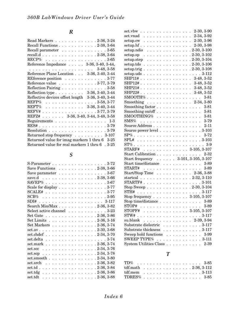
R
Read Markers . . . . . . . . . . . . . 2-36, 3-24Recall Functions . . . . . . . . . . . . 2-38, 3-64Recall parameter . . . . . . . . . . . . . . 3-65recall.d . . . . . . . . . . . . . . . . . 2-38, 3-64RECP% . . . . . . . . . . . . . . . . . . . 3-65Reference Impedance . . . . . 3-36, 3-40, 3-44, . . . . . . . . . . . . . . . . . . . . 3-48, 3-58Reference Plane Location . . . 3-36, 3-40, 3-44REference position . . . . . . . . . . . . . 3-77Reference value . . . . . . . . . . . . 3-77, 3-79Reflection Pairing . . . . . . . . . . . . . . 3-58Reflection type . . . . . . . . . 3-36, 3-40, 3-44Reflective devices offset length 3-36, 3-40, 3-44REFP% . . . . . . . . . . . . . . . . 3-58, 3-77REFT% . . . . . . . . . . . . 3-36, 3-40, 3-44REFV# . . . . . . . . . . . . . . . . . 3-77, 3-79REFZ# . . . . . . . 3-36, 3-40, 3-44, 3-48, 3-58Reguirements . . . . . . . . . . . . . . . . 1-3RES# . . . . . . . . . . . . . . . . . . . . . 3-79Resolution . . . . . . . . . . . . . . . . . . 3-79Returned stop frequency . . . . . . . . . 3-107Returned value for imag markers 1 thru 6 3-25Returned value for real markers 1 thru 6 . 3-25
S
S-Parameter . . . . . . . . . . . . . . . . . 3-72Save Functions . . . . . . . . . . . . 2-38, 3-66Save parameter . . . . . . . . . . . . . . . 3-67save.d . . . . . . . . . . . . . . . . . 2-38, 3-66SAVEP% . . . . . . . . . . . . . . . . . . . 3-67Scale for display . . . . . . . . . . . . . . . 3-77SCALE# . . . . . . . . . . . . . . . . . . . 3-77SCB% . . . . . . . . . . . . . . . . . . . . 3-95SDI# . . . . . . . . . . . . . . . . . . . . 3-117Search Min/Max . . . . . . . . . . . . 2-36, 3-82Select active channel . . . . . . . . . . . . 3-23Set Gate . . . . . . . . . . . . . . . . 2-36, 3-86Set Limits . . . . . . . . . . . . . . . 2-36, 3-16Set Markers . . . . . . . . . . . . . . 2-36, 3-74set.av . . . . . . . . . . . . . . . . . . 2-30, 3-68set.chdef . . . . . . . . . . . . . . . . 2-34, 3-70set.delta . . . . . . . . . . . . . . . . . . . 3-74set.mark . . . . . . . . . . . . . . . . 2-36, 3-74set.scc . . . . . . . . . . . . . . . . . 2-34, 3-76set.scp . . . . . . . . . . . . . . . . . 2-34, 3-78set.smooth . . . . . . . . . . . . . . . 2-34, 3-80set.srch . . . . . . . . . . . . . . . . 2-36, 3-82set.td . . . . . . . . . . . . . . . . . . 2-36, 3-84set.tdg . . . . . . . . . . . . . . . . . 2-36, 3-86set.tdt . . . . . . . . . . . . . . . . . 2-36, 3-88
set.vbw . . . . . . . . . . . . . . . . 2-30, 3-90set.vnad . . . . . . . . . . . . . . . 2-34, 3-92setup.cw . . . . . . . . . . . . . . . 2-30, 3-96setup.hf . . . . . . . . . . . . . . . . 2-30, 3-98setup.ndis . . . . . . . . . . . . . . 2-30, 3-100setup.sp . . . . . . . . . . . . . . . 2-30, 3-102setup.step . . . . . . . . . . . . . . 2-30, 3-104setup.tds . . . . . . . . . . . . . . . 2-30, 3-106setup.trig . . . . . . . . . . . . . . . 2-30, 3-108setup.uds . . . . . . . . . . . . . . . . . . 3-112SHP11# . . . . . . . . . . . . . . . . 3-48, 3-52SHP12# . . . . . . . . . . . . . . . . 3-48, 3-52SHP21# . . . . . . . . . . . . . . . . 3-48, 3-52SHP22# . . . . . . . . . . . . . . . . 3-48, 3-52SMOOTH% . . . . . . . . . . . . . . . . . 3-81Smoothing . . . . . . . . . . . . . . 2-34, 3-80Smoothing factor . . . . . . . . . . . . . . 3-81Smoothing on/off . . . . . . . . . . . . . . 3-81SMOOTHING% . . . . . . . . . . . . . . 3-81SMS% . . . . . . . . . . . . . . . . . . . 3-79Source Address . . . . . . . . . . . . . . . 2-11Source power level . . . . . . . . . . . . . 3-103SP% . . . . . . . . . . . . . . . . . . . . . 3-72SPL# . . . . . . . . . . . . . . . . . . . . 3-103ST% . . . . . . . . . . . . . . . . . . . . . . 3-9STARF# . . . . . . . . . . . . . . 3-105, 3-107Start Calibration . . . . . . . . . . . . . . 2-32Start frequency . . . . . . 3-101, 3-105, 3-107Start time/distance . . . . . . . . . . . . 3-89START# . . . . . . . . . . . . . . . . . . 3-89Start/Stop Time . . . . . . . . . . . 2-36, 3-88startcal . . . . . . . . . . . . . . . . 2-32, 3-110STARTF# . . . . . . . . . . . . . . . . . . 3-101Step Sweep . . . . . . . . . . . . . . 2-30, 3-104STH# . . . . . . . . . . . . . . . . . . . . 3-117Stop frequency . . . . . . . . . . . 3-105, 3-107Stop time/distance . . . . . . . . . . . . . 3-89STOP# . . . . . . . . . . . . . . . . . . . 3-89STOPF# . . . . . . . . . . . . . . 3-105, 3-107STW# . . . . . . . . . . . . . . . . . . . . 3-117su.blank . . . . . . . . . . . . . . . 2-39, 3-94Substrate dielectric . . . . . . . . . . . . 3-117Substrate thickness . . . . . . . . . . . . 3-117Sweep hold functions . . . . . . . . . . . 3-99SWEEP TYPE% . . . . . . . . . . . . . . 3-111System Utilities Class . . . . . . . . . . . 2-39
T
TD% . . . . . . . . . . . . . . . . . . . . 3-85tdf.math . . . . . . . . . . . . . . . 2-36, 3-112tdf.mem . . . . . . . . . . . . . . . . . . 3-113TDRES% . . . . . . . . . . . . . . . . . . 3-85
360B LabWindows Driver User’s Guide
Index 6
TDWIN% . . . . . . . . . . . . . . . . . . 3-85Test Port . . . . . . . . . . . . . . . . . . . 3-11Test Signal Setup . . . . . . . . . . . . . . 2-30Time Domain Functions . . . . . . . . . . 2-35Time Domain Sweep . . . . . . . . 2-30, 3-106TP% . . . . . . . . . . . . . . . . . . . . . 3-11TPE% . . . . . . . . . . . . . . . . . . . . 3-79Trace Data Functions . . . . . . . . . . . . 2-35Trace Functions . . . . . . . . . . . . . . . 2-37TRIGC% . . . . . . . . . . . . . . . . . . 3-109Trigger control . . . . . . . . . . . . . . . 3-109Trigger Selections . . . . . . 2-30, 3-108, 3-110Tutorial . . . . . . . . . . . . . . . . . . . 2-11Type of display . . . . . . . . . . . . . . . 3-93Type: Autoscale on/off . . . . . . . . . . . . 3-79
U
udef.coax . . . . . . . . . . . . . . . 2-32, 3-114udef.mic . . . . . . . . . . . . . . . . . . 3-116udef.micro . . . . . . . . . . . . . . . . . . 2-32udef.wg . . . . . . . . . . . . . . . 2-32, 3-118UL# . . . . . . . . . . . . . . . . . . . . . 3-17UL2# . . . . . . . . . . . . . . . . . . . . . 3-17Upper limit . . . . . . . . . . . . . . . . . 3-17User Defined Coax . . . . . . . . . 2-32, 3-114User Defined Microstrip . . . . . . 2-32, 3-116
User defined parameter name . . . . . . 3-72User Defined Waveguide . . . . . . 2-32, 3-118ut.calcomp . . . . . . . . . . . . . . . . . 3-120ut.disc . . . . . . . . . . . . . . . . 2-38, 3-120ut.inst . . . . . . . . . . . . . . . . . . . 3-122ut.video . . . . . . . . . . . . . . . . 2-39, 3-122
V
Video bandwidth . . . . . . . . . . . . . . 3-91Video Configuration . . . . . . . . . . . . 3-122Video Configurations . . . . . . . . . . . 2-39Video I.F. Bandwidth . . . . . . . . . . . 3-90Video IF Bandwidth . . . . . . . . . . . . 2-30VNA Address . . . . . . . . . . . . . 3-33, 3-111VNA calibration sweep type . . . . . . . . 3-111
W
Waveguide calibration kit . . . . . . . . . 3-55WGKIT% . . . . . . . . . . . . . . . . . . 3-55Width of microstrip . . . . . . . . . . . . 3-117
Z
ZC# . . . . . . . . . . . . . . . . . . . . . 3-117
Index 7/Index 8
Index