371r-98 guide for the analysis, design, and construction ... · this aci guide presents...
TRANSCRIPT

Tastrdc
pgttonlat
Ktw
ACI 371R-98
Guide for the Ana lysis, Design, and Construction of Concrete- Pedestal Water Towers
Reported by ACI Committee 371
Noel J. EverardChairman
Rolf Pawski*
Secretary
Lars F. Balck Chris R. Lamon George B. Rest
Steven R. Close Greg A. Larson Jehangir E. Rudina
August Domel** Stephen W. Meier Bryce P. Simons
David P. Gustafson Jack Moll Michael J. Welsh
Charles S. Hanskat Todd D. Moore
*The Committee expresses sincere appreciation to Rolf Pawski for development of the final presentation of thisGuide, and for correlating and editing the several drafts of this document.
**Served as Committee Secretary 1992-1995.
ACI Committee Reports, Guides, Standard Practices, andCommentaries are intended for guidance in planning, designing, executing, and inspecting construction. This documentis intended for the use of individuals who are competentto evaluate the significance and limitations of its contentand recommendations and who will accept responsibilityfor the application of the material it contains. The AmericanConcrete Institute disclaims any and all responsibility for thestated principles. The Institute shall not be liable for any lossor damage arising therefrom.Reference to this document shall not be made in contracdocuments. If items found in this document are desired bythe Architect/Engineer to be a part of the contract documents,they shall be restated in mandatory language for incorporationby the Architect/Engineer.
371R-
his ACI guide presents recommendations for materials, analysis, design,nd construction of concrete-pedestal elevated water storage tanks. Thesetructures are commonly referred to as composite-style elevated wateranks that consist of a steel water storage tank supported by a cylindricaleinforced concrete-pedestal. This document includes determination ofesign loads, and recommendations for design and construction of theast-in-place concrete portions of the structure.
Concrete-pedestal elevated water-storage tanks are structures thatresent special problems not encountered in typical building designs. Thisuide refers extensively to ACI 318 Building Code Requirements for Struc-
ural Concrete for many requirements, and describes how to apply ACI 318o these structures. Determination of snow, wind, and seismic loads basedn ASCE 7 is included. These loads will conform to the requirements ofational building codes that use ASCE 7 as the basis for environmental
oads. Special requirements, based on successful experience, for the uniquespects of loads, analysis, design and construction of concrete-pedestal
anks are presented.
eywords: analysis; composite tanks; concrete-pedestal tanks; construcion; design; earthquake resistant structures; elevated water tanks; form-ork (construction); loads (forces): dead, live, water, snow, wind and
earthquake loads; load combinations; shear; shear strength; structural anal-ysis; structural design; walls.
ns
-
-
CONTENTSChapter 1—General, p. 371R-2
1.1—Introduction1.2—Scope1.3—Drawings, specifications, and calculatio1.4—Terminology1.5—Notation1.6—Metric units
Chapter 2—Materials, p. 371R-42.1—General2.2—Cements2.3—Aggregates2.4—Water2.5—Admixtures2.6—Reinforcement
Chapter 3—Construction, p. 371R-53.1—General3.2—Concrete3.3—Formwork3.4—Reinforcement3.5—Concrete finishes3.6—Tolerances3.7—Foundations3.8—Grout
ACI 371R-98 became effective February 27, 1998. Copyright 1998, American Concrete Institute.All rights reserved including rights of reproduction and use in any form or by any
means, including the making of copies by any photo process, or by electronic ormechanical device, printed, written, or oral, or recording for sound or visual reproduc-tion or for use in any knowledge or retrieval system or device, unless permission inwriting is obtained from the copyright proprietors.
t
1

371R-2 MANUAL OF CONCRETE PRACTICE
forctinvate waon-
0,00c-dingterioteriation
conaterturaionsoriesen
tane thils.
zent,gth,uralrms, de-
ces,
nt.
re-
se or
-bri-
r
r-re-
e,ef-
ll,teel
-the
atcon-
etankthe
c-ionank
nt
Chapter 4—Design, p. 371R-84.1—General4.2—Loads4.3—Strength requirements4.4—Serviceability requirements4.5—Snow loads4.6—Wind forces4.7—Seismic forces4.8—Support wall4.9—Tank floors4.10—Concrete to tank interface4.11—Foundations4.12—Geotechnical recommendations
Chapter 5—Appu rtenances and accessories,p. 371R-21
5.1—General5.2—Support wall access5.3—Ventilation5.4—Steel tank access5.5—Rigging devices5.6—Above ground piping5.7—Below ground piping and utilities5.8—Interior floors5.9—Electrical and lighting
Chapter 6—References, p. 371R-256.1—Recommended references6.2—Cited references
Appendix A—Commentary on guide for the analysis, design, and construction of concrete-pedestal water t owers, p. 371R-26
CHAPTER 1—GENERAL1.1—Int roduction
The objective of this document is to provide guidancethose responsible for specifying, designing, and construconcrete-pedestal elevated water-storage tanks. Eletanks are used by municipalities and industry for potableter supply and fire protection. Commonly built sizes of ccrete-pedestal water tanks range from 100,000 to 3,00gallons (380 to 11,360 m3). Typical concrete support struture heights range from 25 to 175 ft (8 to 53 m), depenon water system requirements and site elevation. The inof the concrete support structure may be used for maand equipment storage, office space, and other applica
1.2—ScopeThis document covers the design and construction of
crete-pedestal elevated water tanks. Topics include mals, construction requirements, determination of strucloads, design of concrete elements including foundatgeotechnical requirements, appurtenances, and access
Designs, details, and methods of construction are preed for the types of concrete-pedestal tanks shown in Fig. 1.2.This document may be used in whole or in part for otherconfigurations, however, the designer should determinsuitability of such use for other configurations and deta
gd-
0
rl
s.
-i-l,s.t-
ke
1.3—Drawings, specifications, and calculations1.3.1 Drawings and Specifications—Construction docu-
ments should show all features of the work including the siand position of structural components and reinforcemestructure details, specified concrete compressive strenand the strength or grade of reinforcement and structsteel. The codes and standards to which the design confothe tank capacity, and the design basis or loads used insign should also be shown.
1.3.2 Design Basis Documentation—The design coeffi-cients and resultant loads for snow, wind and seismic forand methods of analysis should be documented.
1.4—Terminolo gyThe following terms are used throughout this docume
Specialized definitions appear in individual chapters.Appurtenances and accessories—Piping, mechanical
equipment, vents, ladders, platforms, doors, lighting, andlated items required for operation of the tank.
Concrete support structure—Concrete support elementabove the top of the foundation: wall, ringbeam, and domflat slab tank floor.
Construction documents—Detailed drawings and specifications conforming to the project documents used for facation and construction.
Foundation—The concrete annular ring, raft, or pile opier cap.
Project documents—Drawings, specifications, and geneal terms and conditions prepared by the specifier for procument of concrete-pedestal tanks.
Intermediate floor slabs—One or more structural floorsabove grade, typically used for storage.
Rustication—Shallow indentation in the concrete surfacformed by shallow insert strips, to provide architectural fect on exposed surfaces, usually 3/4 in. (20 mm) deep by 3to 12 in. (75 to 300 mm) wide.
Ringbeam—The concrete element at the top of the waconnecting the wall and dome, and the support for the stank cone.
Wall or support wall—The cylindrical concrete wall supporting the steel tank and its contents, extending from foundation to the ringbeam.
Tank floor—A structural concrete dome, concrete flslab, or a suspended steel floor that supports the tank tents inside the support wall.
Steel liner—A non-structural welded steel membranplaced over a concrete tank floor and welded to the steel to provide a liquid tight container; considered a part of steel tank.
Steel tank—The welded steel plate water containing struture comprised of a roof, side shell, conical bottom sectoutside the support wall, steel liner over the concrete tfloor or a suspended steel floor, and an access tube.
Slab-on-grade—Floor slab inside the wall at grade.
1.5—Notation1.5.1 Loads—The following symbols are used to represe
applied loads, or related forces and moments; Sections 4.3.3and 4.4.2.
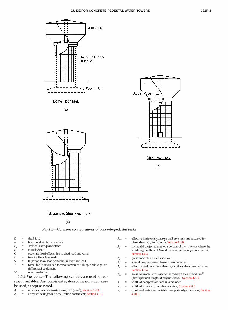
371R-3GUIDE FOR CONCRETE-PEDESTAL WATER TOWERS
(c)
Fig 1.2—Common configurations of concrete-pedestal tanks
, or
p-t ma
the
nt;
D = dead loadE = horizontal earthquake effectEv = vertical earthquake effectF = stored waterG = eccentric load effects due to dead load and waterL = interior floor live loadsS = larger of snow load or minimum roof live loadT = force due to restrained thermal movement, creep, shrinkage
differential settlementW = wind load effect
1.5.2 Variables—The following symbols are used to reresent variables. Any consistent system of measuremenbe used, except as noted. A = effective concrete tension area, in.2 (mm2); Section 4.4.3Aa = effective peak ground acceleration coefficient; Section 4.7.2
y
Acv = effective horizontal concrete wall area resisting factored in-plane shear Vuw, in.2 (mm2); Section 4.8.6
Af = horizontal projected area of a portion of the structure wherewind drag coefficient Cf and the wind pressure pz are constant; Section 4.6.3
Ag = gross concrete area of a section As = area of nonprestressed tension reinforcementAv = effective peak velocity-related ground acceleration coefficie
Section 4.7.4Aw = gross horizontal cross-sectional concrete area of wall, in.2
(mm2) per unit length of circumference; Section 4.8.3b = width of compression face in a memberbd = width of a doorway or other opening; Section 4.8.5be = combined inside and outside base plate edge distances; Section
4.10.5

371R-4 MANUAL OF CONCRETE PRACTICE
-
cen-
);
er,
s;
ft
il
r-
l
ine-
8,
d-e-
and of
bp = effective base plate width; Section 4.10.5bx = cumulative opening width in a distance of 0.78 dw; Section
4.8.6Ca = seismic coefficient based on soil profile type and Aa; Section
4.7.4Ce = combined height and gust response factor; Section 4.6.3Cf = wind force drag coefficient; Section 4.6.3Cr = roof slope factor; Section 4.5.2Cs = seismic design coefficient; Section 4.7.6Cv = seismic coefficient based on soil profile type and Av; Section
4.7.4Cw = wall strength coefficient; Section 4.8.3d = distance from extreme compression to centroid tension rein
forcementdc = distance from the extreme tension fiber to the tension steel
troid, in. (mm); Section 4.4.3dw = mean diameter of concrete support wall; Sections 4.8.3, 4.8.4,
and 4.8.6eg = vertical load eccentricity, in. (mm); Section 4.2.2eo = minimum vertical load eccentricity, in. (mm); Section 4.2.2fc′ = specified compressive strength of concrete, psi (MPa)
= square root of specified compressive strength, psi (MPa)fs = calculated stress in reinforcement at service loads, ksi (MPa
Section 4.4.3fy = specified yield strength of reinforcing steel, psi (MPa)Fi = portion of the total seismic shear V acting at level i; Sections
4.7.8 and 4.7.9Fw = wind force acting on tributary area Af; Section 4.6.2Fx = portion of the seismic shear V acting at level x; Section 4.7.7g = acceleration due to gravity, 32.2 ft/sec2 (9.8 m/sec2); Section
4.7.3h = dome tank floor thickness; Section 4.9.3 h = wall thickness exclusive of any rustications or architectural
relief; Section 4.8 hd = height of a doorway opening; Section 4.8.5 hf = foundation depth measured from original ground line; Fig.
4.12.4I = importance factor; Sections 4.5.2 and 4.6.2k = structure exponent in Equation 4-10b; Section 4.7.7kc = lateral flexural stiffness of concrete support structure; Section
4.7.5 kl = effective unsupported column length; Section 4.8.5lcg = distance from base to centroid of stored water; Sections 4.7.5
and 4.7.9lg = distance from bottom of foundation to centroid of stored wat
in. (mm); Section 4.2.2 li = distance from base to level of Fi; Sections 4.7.7 and 4.7.9lx = distance from base to level under consideration; Sections 4.7.7.
and 4.7.9Mh = wind ovalling moment per unit of height at horizontal section
Section 4.8.4Mo = seismic overturning moment at base; Section 4.7.9Mu = factored moment; Section 4.8.6Mx = seismic overturning moment at distance lx above base; Section
4.7.6n = total number of levels within the structure; Section 4.7.7N = average field standard penetration resistance for the top 100
(30 m); Table 4.7.3Nch = average standard penetration resistance for cohesionless so
layers for the top 100 ft (30 m); Table 4.7.3pg = ground snow load; Section 4.5.2pr = rain-snow surcharge; Section 4.5.2pz = wind pressure at height z; Section 4.6.3p20 = 20 lb/ft2 (0.96 kPa) ground snow load; Section 4.5.2P = foundation load above grade; Fig. 4.12.4Pnw = nominal axial load strength of wall, lb (N) per unit of circumfe
ence; Section 4.8.3Ps = gravity service load; Section 4.11.3Puw = factored axial wall load, lb (N) per unit of circumference; Sec-
tions 4.8.3 and 4.8.5qa = allowable bearing capacity of a shallow foundation; Section
4.12.4qr = ultimate bearing capacity of a shallow foundation; Section 4.12.4
fc′
qs = wind stagnation pressure; Section 4.6.3qu = factored soil bearing pressure; Section 4.12.4Qa = allowable service load capacity of a pile or pier; Section 4.12.5Qr = ultimate capacity of a pile or pier; Section 4.12.5Qu = factored pile or pier load; Section 4.12.5R = seismic response modification coefficient; Section 4.7.4Rd = mean meridional radius of dome tank floor; Section 4.9.3su = average undrained shear strength in top 100 ft (30 m); Table
4.7.3T = fundamental period of vibration of structure, seconds; Section
4.7.5 V = total design lateral force or shear at base of structure; Section
4.7.6Vb = basic wind speed, miles per hour (m/sec); Section 4.6.3Vn = nominal shear strength; Section 4.8.6Vu = factored shear force; Section 4.8.6Vuw = factored shear force acting on an effective shear wall; Section
4.8.6Vx = lateral seismic shear force at level x, a distance lx above base;
Section 4.7.8wi = portion of the total mass whose centroid is at level i, a distance
li above base; Section 4.7.7 ws = distributed snow load; Section 4.5.2wu = factored distributed load; Section 4.9.3 wx = portion of the total mass whose centroid is at level x, a distance
lx above base; Section 4.7.7Wc = weight of concrete below grade; Fig. 4.12.4WL = single lumped mass weight; Section 4.7.5Ws = weight of soil below grade; Fig. 4.12.4WG = total seismic gravity load; Section 4.7.6z = height above ground level; Section 4.6.3zs = quantity limiting distribution of tension reinforcement; Section
4.4.2αc = constant used to compute in-plane nominal shear strength; Sec-
tion 4.8.6 βw = wall slenderness coefficient; Section 4.8.3γE = partial load factor for seismic loads; Section 4.2.3γs = unit weight of soil; Fig. 4.12.4θc = effective curved roof slope measured from the horizontal; Sec-
tion 4.5.1 θg = foundation tilt in degrees; Section 4.2.2 θr = roof slope in degrees measured from the horizontal; Section
4.5.1 νs = average shear wave velocity in top 100 ft (30 m); Table 4.7.3ρ = As /bd, ratio of nonprestressed tension reinforcementρg = As /Ag, ratio of total nonprestressed reinforcementρh = ratio of horizontal distributed shear reinforcement on a vertical
plane perpendicular to Acv; Section 4.8.6ρv = ratio of vertical distributed shear reinforcement on a horizonta
plane of area Acv; Section 4.8.6φ = strength reduction factor; Section 4.3.2ψ = wall opening ratio; Section 4.8.6
1.6 —Metric unitsThe in.-lb system is the basis for units of measurement
this guide, and soft metric conversion is shown in parenthses.
CHAPTER 2—MATERIALS2.1—General
Materials and material tests should conform to ACI 31except as modified in this document.
2.2—CementsCement should conform to ASTM C 150 or C 595, exclu
ing Types S and SA, which are not intended as principal cmenting agents for structural concrete. The same brand type of cement should be used throughout the constructioneach major element.
371R-5GUIDE FOR CONCRETE-PEDESTAL WATER TOWERS
ndalergr fro
,
an8
-nt
in-oron
u-
rth th.
rm
24
-
ro
orbe
nts of
ld vi-ent,
ix-mp
ionent
ur-t sag
eibleultsring.- of
eayblehel toerigh-
e of
inte-hasma-rete
eon-in-
d atorsh the
Idshed
ulding.bi-M
intion
2.3—AggregatesConcrete aggregates should conform to ASTM C 33 a
ACI 318. Aggregates used in the concrete support wshould be suitable for exterior exposed surfaces. Whsandblasting or other finishing techniques that expose aggate are used, the fine and coarse aggregate should bea consistent source to maintain uniformity of color.
2.4—WaterWater should conform to ASTM C 94.
2.5—AdmixturesAdmixtures should conform to ACI 318.
2.6—Reinforcement2.6.1 Bar reinforcement—Deformed bar reinforcement
should conform to ASTM A 615/A 615M, A 617/A 617Mor A 706/A 706M.
2.6.2 Welded wire reinforcement—Welded wire reinforce-ment should conform to ASTM A 185 or A 497.
CHAPTER 3—CONSTRUCTION3.1—General
3.1.1 Reference Standard—Concrete, formwork, rein-forcement, and details of the concrete support structure foundations should conform to the requirements of ACI 31except as modified in this document.
3.1.2 Quality Assurance—A quality assurance plan to verify that the construction conforms to the design requiremeshould be prepared. It should include the following:
(a) Inspection and testing required, forms for recording spections and testing, and the personnel performing such w;
(b) Procedures for exercising control of the constructiwork, and the personnel exercising such control;
(c) Methods and frequency of reporting, and the distribtion of reports.
3.2—Concrete3.2.1 General—Concrete mixtures should be suitable fo
the placement methods, forming systems and the weaconditions during concrete construction, and should satisfyrequired structural, durability and architectural parameters
3.2.2—Concrete quality3.2.2.1 Water-cementitious material ratio—The water-
cementitious material ratio should not exceed 0.50.3.2.2.2 Specified compressive strength—The minimum
specified compressive strength of concrete should confoto the following:
(a) concrete support structure = 4000 psi (28 MPa);(b) foundations and intermediate floors = 3500 psi (
MPa); and(c) slabs-on-grade (see Table 5.8.2).
3.2.2.3 Air-entrainment—Concrete should be air-entrained in accordance with ACI 318.
3.2.3 Proportioning—Proportioning of concrete mixturesshould conform to the requirements of ACI 318 and the pcedure of ACI 211.1.
3.2.3.1 Workability—The proportions of materials forconcrete should be established to provide adequate wability and proper consistency to permit concrete to
lee-m
d,
s
k
ere
-
k-
worked readily into the forms and around reinforcemewithout excessive segregation or bleeding for the methodplacement and consolidation employed.
3.2.3.2 Slump—The slump of concrete provided shoube based on consideration of the conveying, placing andbration methods as well as the geometry of the componand should conform to the following:
(a) Concrete without high-range water-reducing admtures (HRWRA) should be proportioned to produce a sluof 4 in. (100 mm) at the point of placement.
(b) Slump should not exceed 8 in. (200 mm) after additof HRWRA, unless the mix has been proportioned to prevsegregation at higher slump.
(c) The slump of concrete to be placed on an inclined sface should be controlled such that the concrete does noor deform after placement and consolidation.
3.2.3.3 Admixtures—Admixtures may be used to achievthe required properties. Admixtures should be compatsuch that their combined effects produce the required resin hardened concrete as well as during placement and cu
3.2.4 Concrete production—Measuring, mixing and transporting of concrete should conform to the requirementsACI 318 and the recommendations of ACI 304R.
3.2.4.1 Slump adjustment—Concrete that arrives at thproject site with slump below that suitable for placing mhave water added within limits of the slump and permissiwater-cementitious material ratio of the concrete mix. Twater should be incorporated by additional mixing equaat least half of the total mixing time required. No watshould be added to the concrete after plasticizing or hrange water-reducing admixtures have been added.
3.2.5 Placement—Placing and consolidation of concretshould conform to ACI 318, and the recommendationsACI 304R and ACI 309R.
3.2.5.1 Depositing and consolidation—Placementshould be at such a rate that the concrete that is being grated with fresh concrete is still plastic. Concrete that partially hardened or has been contaminated by foreign terials should not be deposited. Consolidation of concshould be with internal vibrators.
3.2.5.2 Support wall—Drop chutes or tremies should bused in walls and columns to avoid segregation of the ccrete and to allow it to be placed through the cage of reforcing steel. These chutes or tremies should be moveshort intervals to prevent stacking of concrete. Vibratshould not be used to move the mass of concrete througforms.
3.2.6 Curing—Curing methods should conform to AC318 and the requirements of ACI 308. Curing methoshould be continued or effective until concrete has reac70 percent of its specified compressive strength fc′ unless ahigher strength is required for applied loads. Curing shocommence as soon as practicable after placing and finishCuring compounds should be membrane forming or comnation curing/surface hardening types conforming to ASTC 309.
3.2.7—Weather3.2.7.1 Protection—Concrete should not be placed
rain, sleet, snow, or extreme temperatures unless protec
371R-6 MANUAL OF CONCRETE PRACTICE
as
-
-
a
yline c-d
mecondeam
tiotedul
03
C
e-preora
-tioallcoe r
i-truby
edan d
ondaete diithie dirocin
ive
ithe
onuc-
ng
n-eling
n-elarc,nts
n-ately
gthynta-
edi-rtensnt
d 1/
-n-
is provided. Rainwater should not be allowed to incremixing water nor to damage surface finish.
3.2.7.2 Cold weather—During cold weather, the recommendations of ACI 306 should be followed.
3.2.7.3 Hot weather—During hot weather the recommendations of ACI 305R should be followed.
3.2.8 Testing, evaluation and acceptance—Material test-ing, type and frequency of field tests, and evaluation andceptance of testing should conform to ACI 318.
3.2.8.1 Concrete strength tests—At least four cylindersshould be molded for each strength test required. Two cders should be tested at 28 days for the strength test. Oninder should be tested at 7 days to supplement the 28tests. The fourth cylinder is a spare to replace or suppleother cylinders. Concrete temperature, slump, and air tent measurements should be made for each set of cylinUnless otherwise specified in the project documents, spling of concrete should be at the point of delivery.
3.2.8.2 Early-age concrete strength—Where knowledgeof early-age concrete strength is required for construcloading, field-cured cylinders should be molded and tesor one of the following non-destructive test methods shobe used when strength correlation data are obtained:
(a) Penetration resistance in accordance with ASTM C 8(b) Pullout strength in accordance with ASTM C 900;(c) Maturity-factor method in accordance with ASTM
1074.3.2.8.3 Reporting—A report of tests and inspection r
sults should be provided. Location on the structure resented by the tests, weather conditions, and details of stand curing should be included.
3.2.9—Joints and embedments3.2.9.1 Construction joints—The location of construc
tion joints and their details should be shown on construcdrawings. Horizontal construction joints in the support wshould be approximately evenly spaced. The surface of crete construction joints should be cleaned and laitancmoved.
3.2.9.2 Expansion joints—Slabs-on-grade and intermedate floor slabs not structurally connected to the support sture should be isolated from the support structure premolded expansion joint filler.
3.2.9.3 Contraction joints—Contraction joints are onlyused with slabs-on-grade (see Section 5.8.2.3).
3.2.9.4 Embedments—Sleeves, inserts, and embedditems should be installed prior to concrete placement, should be accurately positioned and secured againstplacement.
3.3—Formwork3.3.1—GeneralFormwork design, installation, and removal should c
form to the requirements of ACI 318 and the recommentions of ACI 347R. Formwork should ensure that concrcomponents of the structure will conform to the correctmensions, shape, alignment, elevation and position wthe established tolerances. Formwork systems should bsigned to safely support construction and expected envmental loads, and should be provided with ties and bra
e
c-
-yl-aynt-
rs.-
n,
d
;
-ge
n
n-e-
c-
dis-
--
-ne-
n-g
as required to prevent the leakage of mortar and excessdeflection.
3.3.1.1 Facing material—Facing material of forms usedabove finished grade should be metal, or plywood faced wplastic or coated with fiberglass. Any form material may bused for below-grade applications.
3.3.1.2 Chamfers—Exposed corners should be formedwith chamfers 3/4 in. (20 mm) or larger.
3.3.1.3 Concrete strength—The minimum concretecompressive strength required for safe removal of any sup-ports for shored construction, or the safe use of constructiembedments or attachments should be shown on constrtion drawings, or instructions used by field personnel.
3.3.1.4 Cleaning and coating—Form surfaces should becleaned of foreign materials and coated with a non-stainirelease agent prior to placing reinforcement.
3.3.1.5 Inspection—Prior to placing concrete, formsshould be inspected for surface condition, accuracy of aligment, grade and compliance with tolerance, reinforcing steclearances and location of embedments. Shoring and bracshould be checked for conformance to design.
3.3.2—Foundations3.3.2.1 Side forms—Straight form panels that circum-
scribe the design radius may be used to form circular foudation shapes. Circular surfaces below final ground levmay have straight segments that do not exceed 30 deg of and surfaces exposed to view may have straight segmethat do not exceed 15 deg of arc.
3.3.2.2 Top forms—Forms should be provided on topsloping surfaces steeper than 1 vertical to 2.5 horizontal, uless it can be demonstrated that the shape can be adequmaintained during concrete placement and consolidation.
3.3.2.3 Removal—Top forms on sloping surfaces may beremoved when the concrete has attained sufficient strento prevent plastic movement or deflection. Side forms mabe removed when the concrete has attained sufficiestrength such that it will not be damaged by removal opertions or subsequent load.
3.3.3—Support wall3.3.3.1 Wall form—The support wall should be con-
structed using a form system having curved, prefabricatform segments of the largest practical size in order to minmize form panel joints. Formwork should be designed folateral pressures associated with full height plastic concrehead. Bracing should be provided for stability, constructiorelated impact loading, and wind loads. Working platformthat allow access for inspection and concrete placemeshould be provided.
3.3.3.2 Deflection—Deflection of facing material be-tween studs as well as studs and walers should not excee400 times the span during concrete placement.
3.3.3.3 Rustications—A uniform pattern of vertical andhorizontal rustications to provide architectural relief is recommended for exterior wall surfaces exposed to view. Costruction joints should be located in rustications.
3.3.3.4 Form ties—Metal form ties that remain withinthe wall should be set back 11/2 in. (40 mm) from the con-crete surface.
371R-7GUIDE FOR CONCRETE-PEDESTAL WATER TOWERS
rem
kinipicaiger
ed b rewnld.
drs
cinret b
to
-prennt
t in1in, ols
ventent
t tocast
up- barce
ithdednd
withlop-raw-
-25rce-
-n onuldrcent
dndcesure.d andcon-
pt sur-
s
andss a
ture
-cast
uffi- leftles
3.3.3.5 Removal—Vertical formwork not supporting theweight of the component may be removed when the conchas reached sufficient strength such that it will not be daaged by the removal operation and subsequent loads.
3.3.4—Tank floor3.3.4.1 Design—Formwork for the flat slab or dome tan
floor should be designed to support construction loads cluding weight of forms, plastic concrete, personnel, equment, temporary storage, and impact forces. Unsymmetrplacement of concrete should be considered in the desCamber to offset concrete weight should be provided whdeflection would result in out-of-tolerance construction.
3.3.4.2 Removal—Forms should remain in place until thconcrete has gained sufficient strength not to be damageremoval operations and subsequent loads. The minimumquired concrete strength for form removal should be shoon construction drawings or instructions issued to the fie
3.4—Reinforcement3.4.1 General—Reinforcement should be clearly indicate
on construction drawings and identified by mark numbethat are used on the fabrication schedule. Location, spaas well as lap splice lengths of reinforcement, and conccover should be shown. Symbols and notations shouldprovided to indicate or clarify placement requirements.
3.4.2 Fabrication—The details of fabrication, includinghooks and minimum diameter of bends, should conformthe requirements of ACI 318 and ACI 315.
3.4.3 Placement—Reinforcement should be accurately positioned, supported and securely tied and supported to vent displacement of the steel during concrete placemBar spacing limits and surface condition of reinforcemeshould conform to the requirements of ACI 318.
3.4.3.1 Concrete cover—The following minimum con-crete cover should be provided for reinforcement in casplace concrete for No. 11 (36) bar, W31 (MW200) or D3(MD200) wire, and smaller. Cover is measured at the thnest part of the wall, at the bottom of rustication groovesbetween the raised surfaces of architectural feature pane
3.4.3.2 Supports—Supports for reinforcement shouldconform to the following:
Minimum cover,in. (mm)
(a) Concrete foundations permanently exposed to earth: Cast against earth 3 (75) Cast against forms or mud slabs, or top reinforcement: No. 6 (19) bar, W45 (MW290) or D45 (MD290) wire, and larger 2 (50)
No. 5 (16) bar, W31 (MW200) or D31 (MD200) wire, and smaller 11/2 (40)
(b) Concrete support structure: Exterior surfaces: No. 6 (19) bar, W45 (MW290) or D45 (MD290) wire, and larger 2 (50)
No. 5 (16) bar, W31 (MW200) or D31 (MD200) wire, and smaller 11/2 (40)
Interior surfaces 1 (25) Sections designed as beams or colums 11/2 (40)(c) Tank floors and intermediate floor slabs 11/2 (40)
te-
--l
n.e
y-
gee
e-t.
-r.
(a) The number of supports should be sufficient to preout-of-tolerance deflection of reinforcement, and to prevoverloading any individual support;
(b) Shallow foundation reinforcement placed adjacenthe ground or working slab should be supported by preconcrete block, metal or plastic bar supports;
(c) Reinforcement adjacent to formwork should be sported by metal or plastic bar supports. The portions ofsupports within 1/2 in. (13 mm) of the concrete surfashould be noncorrosive or protected against corrosion;
(d) Support wall reinforcement should be provided wplastic supports. Maximum spacing of supports for welwire fabric should be 5 ft (1.5 m) centers, horizontally avertically.
3.4.4—Development and splices3.4.4.1 Development and splice lengths—Development
and splices of reinforcement should be in accordance ACI 318. The location and details of reinforcement devement and lap splices should be shown on construction dings.
3.4.4.2 Welding—Welding of reinforcement should conform to AWS D1.4. A full welded splice should develop 1percent of the specified yield strength of the bar. Reinfoment should not be tack welded.
3.4.4.3 Mechanical connections—The type, size, and location of any mechanical connections should be showconstruction drawings. A full mechanical connection shodevelop in tension or compression, as required, 125 peof the specified yield strength of the bar.
3.5—Concrete finishes3.5.1—Surface repair
3.5.1.1 Patching materials—Concrete should be patchewith a proprietary patching material or site-mixed portlacement mortar. Patching material for exterior surfashould match the surrounding concrete in color and text
3.5.1.2 Repair of defects—Concrete should be repaireas soon as practicable after form removal. Honeycombother defective concrete should be removed to sound crete and patched.
3.5.1.3 Tie holes—Tie holes should be patched, excethat manufactured plastic plugs may be used for exteriorfaces.
3.5.2 Formed surfaces—Finishing of formed surfaceshould conform to the following:
(a) Exterior exposed surfaces of the support structurefoundations should have a smooth as-cast finish, unlespecial formed finish is specified;
(b) Interior exposed surfaces of the support strucshould have a smooth as-cast finish;
(c) Concrete not exposed to view may have a rough asfinish.
3.5.2.1 Rough as-cast finish—Any form facing materialmay be used, provided the forms are substantial and sciently tight to prevent mortar leakage. The surface iswith the texture imprinted by the form. Defects and tie hoshould be patched and fins exceeding 1/4 in. (6 mm) in heightshould be removed.

371R-8 MANUAL OF CONCRETE PRACTICE
de i tiechi
she
s
e-:truc
cing
no m)
d b nonot re an
-ents
e and
d en-.
-e a
-tet- or- to8)
ldent
ete
e-
rstion
tideduld be-ace
ae in
te.
m orrete.k,
hy-
-estalruc-
toete
3.5.2.2 Smooth as-cast finish—Form facing material anconstruction should conform to Section 3.3. The surfacleft with the texture imprinted by the form. Defects andholes should be patched and fins should be removed by ping or rubbing.
3.5.2.3 Special form finish—A smooth as-cast finish iproduced, after which additional finishing is performed. Ttype of additional finishing required should be specified.
3.5.3 Trowel finishes—Unformed concrete surfaceshould be finished in accordance with the following: • Slabs-on-grade and intermediate floor slabs—steel
trowel;• Dome and flat slab tank floors—floated;• Foundations—floated;• Surfaces receiving grout—floated.
3.6—Tolerances3.6.1 Concrete tolerances—Tolerances for concrete and r
inforcement should conform to ACI 117 and the following(a) Dimensional tolerances for the concrete support s
ture:Variation in thickness:
wall: –3.0 percent, +5.0 percentdome: –6.0 percent, +10 percent
Support wall variation from plumb:in any 5 ft (1.6 m) of height (1/160): 3/8 in. (10 mm)in any 50 ft (16 m) of height (1/400): 1.5 in.
(40 mm)maximum in total height: 3 in. (75 mm)
Support wall diameter variation: 0.4 percentnot to exceed 3 in. (75 mm)
Dome tank floor radius variation: 1.0 percentLevel alignment variation:
from specified elevation: 1 in. (25 mm)from horizontal plane: 1/2 in. (13 mm)
(b) The offset between adjacent pieces of formwork famaterial should not exceed the following:
Exterior exposed surfaces: 1/8 in. (3 mm)Interior exposed surfaces: 1/4 in. (6 mm)Unexposed surfaces: 1/2 in. (13 mm)(c) The finish tolerance of troweled surfaces should
exceed the following when measured with a 10 ft (3straightedge or sweep board:
Exposed floor slab: 3/8 in. (6 mm)Tank floors: 3/4 in. (20 mm)Concrete support for suspended steel floor tank: 1/4 in.
(6 mm)3.6.2 Out-of-tolerance construction—The effect on the
structural capacity of the element should be determinethe responsible design professional if construction doesconform to Section 3.6.1. When structural capacity is compromised, repair or replacement of the element is noquired unless other governing factors, such as lack of fitaesthetics, require remedial action.
3.7—Foundations3.7.1 Reinforced Concrete—Concrete, formwork, and re
inforcement should conform to the applicable requiremof Chapter 3.
s
p-
-
t
yt
t-
d
3.7.2—Earthwork
3.7.2.1 Excavations—Foundation excavations should bdry and have stable side slopes. Applicable safety standardsregulations should be followed in constructing excavations.
3.7.2.2 Inspection—Excavations should be inspecteprior to concrete construction to ensure that the materialcountered reflects the findings of the geotechnical report
3.7.2.3 Mud mats—A lean concrete mud mat is recommended to protect the bearing stratum, and to providworking surface for placing reinforcement.
3.7.2.4 Backfill—Backfill should be placed and compacted in uniform horizontal lifts. Fill inside the concrewall should conform to Section 5.8.2.4. Fill material ouside the concrete wall may be unclassified soils free ofganic matter and debris. Backfill should be compacted90 to 95 percent standard Proctor density (ASTM D 69or greater.
3.7.2.5 Grading—Site grading around the tank shouprovide positive drainage away from the tank to prevponding of water in the foundation area.
3.7.3 Field inspection of deep foundations—Field inspec-tion by a qualified inspector of foundations and concrwork should conform to the following:
(a) Continuous inspection during pile driving and placment of concrete in deep foundations;
(b) Periodic inspection during construction of drilled pieor piles, during placement of concrete, and upon compleof placement of reinforcement.
3.8—Grout3.8.1 Steel liner—Unformed steel liner plates that do no
match the shape of the concrete floor may be used, provthe liner plate is grouted after welding. The steel liner shobe constructed with a 1 in. (25 mm) or larger grout spacetween the liner plate and the concrete member. The spshould be completely filled with a flowable grout usingprocedure that removes entrapped air. Provide anchoragareas where the grout pressure is sufficient to lift the pla
3.8.2 Base plate—A base plate used for the steel bottoconfiguration should be constructed with a 1 in. (25 mm)larger grout space between the base plate and the concThe space should be completely filled with a non-shrinnon-metallic grout conforming to Section 4.10.5.6. Groutshould be placed and achieve required strength beforedrotesting the tank.
CHAPTER 4—DESIGN4.1—General
4.1.1 Scope—This chapter identifies the minimum requirements for the design and analysis of a concrete-pedelevated water tank incorporating a concrete support stture, a steel storage tank, and related elements.
4.1.2 Design of concrete support structure—Analysis anddesign of the concrete support structure should conformACI 318, except as modified here. Design of the concrsupport structure elements should conform to Sections 4.8through 4.10.

371R-9GUIDE FOR CONCRETE-PEDESTAL WATER TOWERS
,tors.
urant
s aog
onnal
n a
ec-
ds IV
tur
l
r
eplaib-ad
inen o
ent dwa
le-
igntion
con-s.
,, theture thead
be
on-ec-
ired
-n:
nde-cant:nd
ns
re-ild-
heere
4.1.3 Design of steel storage tank—The materials, designfabrication, erection, testing, and inspection of the steel sage tank should conform to recognized national standard
4.1.4—Design of other elements4.1.4.1 Concrete members—Design of concrete mem-
bers such as foundations, floor slabs, and similar structmembers should conform to ACI 318, and the requiremeof Sections 4.11 and 5.8.
4.1.4.2 Non-concrete members—Design of non-concreterelated elements such as appurtenances, accessoriestructural steel framing members should conform to recnized national standards for the type of construction.
4.1.4.3 Safety related components—Handrails, ladders,platforms, and similar safety related components should cform to the applicable building code, and to OccupatioSafety and Health Administration standards.
4.1.5 Unit weight—The unit weight of materials used ithe design for the determination of gravity loads should befollows, except where materials are known to differ or spifications require other values:
(a) Reinforced concrete: 150 lb/ft3 (2400 kg/m3);(b) Soil backfill: 100 lb/ft3 (1600 kg/m3);(c) Water: 62.4 lb/ft3 (1000 kg/m3);(d) Steel: 490 lb/ft3 (7850 kg/m3);
4.2—Loads4.2.1 General—The structure should be designed for loa
not less than those required for an ASCE 7 Categorystructure, or by the applicable building code.
4.2.2 Structural loads—The loads in Section 4.2.2.1through 4.2.2.8 should be considered to act on the strucas a whole.
4.2.2.1 Dead loads—The weight (mass) of structuracomponents and permanent equipment.
4.2.2.2 Water load—The load produced by varying watelevels ranging from empty to overflow level.
4.2.2.3 Live loads—Distributed and concentrated livloads acting on the tank roof, access areas, elevated forms, intermediate floors or equipment floors. The distruted roof live load should be the greater of snow lodetermined in Section 4.5, or 15 lb/ft2 (0.72 kPa) times thehorizontal projection of the roof surface area to the eave lUnbalanced loading should be considered in the desigthe roof and its supporting members.
4.2.2.4 Environmental loads—Environmental loadsshould conform to:
(a) Snow loads: Section 4.5;(b) Wind forces: Section 4.6;(c) Seismic forces: Section 4.7.
4.2.2.5 Vertical load eccentricity—Eccentricity of deadand water loads that cause additional overturning momto the structure as a whole should be accounted for in thesign. The additional overturning moment is the dead and ter load times the eccentricity eg, which should not be takenas less than
(4-1a)eg eolg
400---------+=
-
ls
nd-
-
s
e
t-
.f
se--
The minimum vertical load eccentricity eo is 1 in. (25 mm). Where tilting of the structure due to non-uniform sett
ment is estimated to exceed 1/800, the eccentricity eg shouldnot be taken as less than
(4-1b)
4.2.2.6 Construction loads—Temporary loads resultingfrom construction activity should be considered in the desof structural components required to support construcloads.
4.2.2.7 Creep, shrinkage, and temperature—The effectsof creep, shrinkage, and temperature effects should besidered. ACI 209R provides guidance for these condition
4.2.2.8 Future construction—Where future constructionsuch as the addition of intermediate floors is anticipatedload effects should be included in the original design. Fuconstruction dead and live loads should be included inGroup 1 load combinations. Only that portion of the deload D existing at the time of original construction shouldincluded in the Group 2 load combinations.
4.2.3 Factored load combinations—Load factors and loadcombinations for the Strength Design Method should cform to the following. The load terms are as defined in Stion 1.6.1.
4.2.3.1 Group 1 load combinations—Where the structur-al effects of applied loads are cumulative the requstrength should not be less than:
Load Combination:U1.1 1.4D + 1.6FU1.2 1.4(D + G) + 1.6F + 1.7(S + L)U1.3 1.1(D + G) + 1.2F + 1.3(L + W)U1.4 γE [1.2(D + F) + 0.5(G + L) + E] + Ev
4.2.3.2 Group 2 load combinations—Where D, L, or Freduce the effect of W or E, as in uplift produced by overturning moment, the required strength should not be less tha
Load Combination:U2.1 0.9D + 1.3WU2.2 γE [0.9(D + F) + E] + Ev
4.2.3.3 Differential settlement, creep, shrinkage, atemperature—Where structural effects of differential settlment, creep, shrinkage or temperature effects are signifi1.4T should be included with Load Combinations U1.1 aU1.2, and 1.1T should be included with Load CombinatioU1.3 and U1.4. Where structural effects T are significant:1.1T should be included with Group 2 loads when T is addi-tive to W or E.
4.2.3.4 Vertical seismic load effect—The vertical seismicload effect Ev in Eq. U1.4 and U2.2 should conform to the quirements of the project documents, or the applicable buing code. Where ASCE 7 is specified, Ev is γE 0.5Ca (D + F).
4.2.3.5 Partial seismic load factor—The partial seismicload factor γE should conform to the requirements of tproject documents, or the applicable building code. WhASCE 7 is specified, γE is 1.1 for concrete elements.
eg eo lg1
800--------- θgtan+
+=

371R-10 MANUAL OF CONCRETE PRACTICE
he
- ser
-an:
ndle-cantandns
theable
uldn th
- to
d
in ac318torectorss of
Un-tion
-andini-
veryleast
ed ifone-
uldce at
uld
ions
-indi-
d beps, or
o di-
-srn fi-0
of7 forhere
on
xi-con-hich
om
or
elldou-
4.2.4 Unfactored load combinations—Unfactored serviceload combinations should conform to the following. Tload terms are as defined in Section 1.6.1.
4.2.4.1 Group 1 load combinations—Where the structural effects of applied loads are cumulative the unfactoredvice load combination should not be less than:
Load Combination:S1.1 D + FS1.2 D + F + G + S + LS1.3 0.75(D + F + G + L + W)S1.4 0.75[D + F + G + L + E] + EV
4.2.4.2 Group 2 load combinations—Where D, L, or Freduce the effect of W or E, as in uplift produced by overturning moment, the required strength should not be less th
Load Combination:S2.1 0.75(D + W)S2.2 0.75[D + F + E] + Ev
4.2.4.3 Differential settlement, creep, shrinkage, atemperature—Where structural effects of differential settment, creep, shrinkage or temperature effects are signifi1.0T should be included with Load Combinations S1.1 S1.2, and 0.75T should be included with Load CombinatioS1.3 and S1.4. Where structural effects T are significant:0.75T should be included with Group 2 loads when T is ad-ditive to W or E.
4.2.4.4 Vertical seismic load effect—The vertical seis-mic load effect Ev in Eq. S1.4 and S2.2 should conform to requirements of the project documents, or the applicbuilding code. Where ASCE 7 is specified, Ev is 0.75 [0.5Ca(D + F)].
4.3—Strength requirements4.3.1 General—Concrete portions of the structure sho
be designed to resist the applied loads that may act ostructure and should conform to this document.
4.3.1.1 Specified concrete strength—Specified compressive strength fc′ of concrete components should conformSection 3.2.2.2 and applicable sections of Chapter 4.
4.3.1.2 Specified strength for reinforcement—The speci-fied yield strength of reinforcement fy should not excee80,000 psi (550 MPa).
4.3.2—Design methods4.3.2.1 Strength design method—Structural concrete
members should be proportioned for adequate strength cordance with the Strength Design provisions of ACI and this document. Loads should not be less than the facloads and forces in Section 4.2.3. Strength reduction faφ should conform to ACI 318 and to applicable sectionChapter 4.
4.3.2.2 Alternate design method—The Alternate DesignMethod of ACI 318 is an acceptable method for design.factored load combinations should conform to Sec4.2.4.
4.3.3—Minimum reinforcement4.3.3.1 Flexural members—Where flexural reinforce
ment is required by analysis in the support structure foundations supported by piling and drilled piers, the mmum reinforcement ratio p should not be less than 3 /fynor 200/fy in in.-lb units (0.25 /fy nor 1.4/fy in SI units).
fc′fc′
-
:
e
-
d
A smaller amount of reinforcement may be used if at esection the area of tensile reinforcement provided is at one-third greater than that required by analysis.
4.3.3.2 Direct tension members—In regions of signifi-cant direct tension the minimum reinforcement ratiopgshould not be less than 5 /fy in in.-lb units (0.42 /fy inSI units). A smaller amount of reinforcement may be usthe area of tensile reinforcement provided is at least third greater than that required by analysis.
4.4—Serviceability requirements4.4.1 General—Concrete portions of the structure sho
conform to this document to ensure adequate performanservice loads. The following should be considered.
(a) Deflection of flexural beam or slab elements shoconform to ACI 318.
(b) Control of cracking should conform to Section 4.4.2and applicable sections of Chapter 4.
(c) Settlement of foundations should conform to Sect4.12.3 and 4.12.5.
4.4.2 Control of cracking—Cracking and control of cracking should be considered at locations where analysis cates flexural tension or direct tension stresses occur.
Where control of cracking is required, sections shoulproportioned such that quantity zs does not exceed 145 kiper inch (25,400 N/mm) for sections subjected to flexure130 kips per in. (22,800 N/mm) for sections subjected trect tension. The quantity zs is determined by:
(4-2)
Calculated stress in reinforcement fs is for Load Combination S1.1 in Section 4.2.4.1. Alternatively, fs may be taken a60 percent of the specified yield strength fy. The clear coveused in calculating the distance from the extreme tensiober to the tension steel centroid dc should not exceed 2 in. (5mm) even though the actual cover is larger.
4.5—Snow Loads4.5.1—General
4.5.1.1 Scope—This section covers determination minimum snow loads for design and is based on ASCE Category IV structures. Larger loads should be used wrequired by the applicable building code.
4.5.1.2 Definitions—Certain terms used in this sectiare defined as follows:
Crown—highest point of the roof at centerline of tank.Eaves—highest level at which the tank diameter is ma
mum; or the 70-deg point of the roof slope of curved or ical roofs, if present. The 70-deg point is the radius at wthe roof slope is 70 deg measured from the horizontal.
Cone roof—monoslope roof having a constant slope frcrown to eaves.
Conical roof—a cone roof combined with an edge conea doubly curved edge segment.
Curved roof—dome, ellipsoidal, or other continuous shroofs with increasing slope from crown to eaves; or the bly curved portion of a conical roof.
fc′ fc′
zs fs dcA3=
371R-11GUIDE FOR CONCRETE-PEDESTAL WATER TOWERS
he
ow
ewn
gowtal
ns
o-
n
duend
tha
is einntig
y
oribubenea th
i- o
be
po-nualter-ind
- up-
ts.
ted
pex
r
one
rizede of toe of
ver
red
indilee aht,
Roof slope θr—roof slope at a point measured from thorizontal.
Effective curved roof slope θc—slope of a straight linefrom the eaves (or the 70-deg point if present) to the crof a curved roof, or a conical roof.
4.5.1.3 Limitations—The provisions of Section 4.5 arapplicable to cone, conical, and curved roofs concave doward without steps or abrupt changes in elevation.
4.5.2 Roof snow load—The unfactored snow load actinon the structure is the sum of the uniformly distributed snload ws acting on any portion of a roof times the horizonprojected area on which ws acts. The uniformly distributedsnow load ws is the larger value determined in Sectio4.5.2.1 and 4.5.2.2.
4.5.2.1 Sloped roof snow load—Portions of a roof havinga slope θr exceeding 70 deg should be considered freesnow load. Where roof slope θr is 70 deg or less, the distributed snow load is given by
ws = 0.76 Cr I pg (4-3a)
The ground snow load pg is in accordance with Sectio4.5.2.3, and the roof slope factor Cr is in accordance withSection 4.5.2.4. The snow importance factor I is 1.2.
4.5.2.2 Minimum snow load—The minimum snow loadacting on cone roofs with slope θr less than 15 deg ancurved roofs with slope θc less than 10 deg is the larger valdetermined from Eq. (4-3b) and (4-3c) when the grousnow load pg is greater than zero
ws = Cr p20 I for pg > p20 (4-3b)
ws = Cr (I pg + pr) for pg ≤ p20 (4-3c)
where p20 = 20 lb/ft2 (0.96 kPa) ground snow loadThe rain-snow surcharge pr is 5 lb/ft2 (0.24 kPa). For roof
slopes steeper than 1 vertical to 24 horizontal (greater 2.38 deg from the horizontal) it may be reduced by 0.24 I pgup to a maximum reduction of 5 lb/ft2 (0.24 kPa).
4.5.2.3 Ground snow load—The ground snow load pgshould be based on an extreme-value statistical analysweather records using a 2 percent annual probability of bexceeded (50-year mean recurrence interval). In the couous United States and Alaska ground snow load pg shouldbe determined from Fig. 7-1 or Table 7-1 in ASCE 7.
4.5.2.4 Roof slope factor—The roof slope factor at anpoint on the roof is given by:
Cr = 1.27 – θr / 55, not greater 1.0 nor less than zero. Fcurved roofs or portions of roofs that are curved the distrtion of snow load should be assumed to vary linearly tween points at 15 and 30 deg, and the eaves. Liinterpolation should be used where the roof slope ateaves is less than 70 deg.
4.6—Wind forces4.6.1 Scope—This section covers determination of min
mum service load wind forces for design, and is based
n
-
f
n
ASCE 7 for Category IV structures. Larger loads shouldused where required by the applicable building code.
4.6.2—Wind speed
4.6.2.1 Basic wind speed—The basic wind speed Vb isthe 3-sec gust speed at 33 ft (10 m) above ground for Exsure C category, and is associated with a 2 percent anprobability of being exceeded (50-yr mean recurrence inval). In the contiguous United States and Alaska basic wspeed Vb may be determined from Fig. 6-1 in ASCE 7.
4.6.2.2 Wind speed-up—Wind speed-up over hills and escarpments should be considered for structures sited on theper half of hills and ridges or near the edge of escarpmen
4.6.3 Design wind force—The service load wind force Wacting on the structure is the sum of the forces calculafrom Section 4.6.3.1.
4.6.3.1—The design wind force Fw acting on tributaryarea Af is
Fw = Cf pz Af (4-4)
where
Cf = wind force drag coefficient
= 0.6, for cylindrical surfaces
= 0.5, for double curved surfaces or cones with an aangle > 30 deg.
The wind pressure pz at height z above ground level is inaccordance with Section 4.6.3.2.
4.6.3.2—Wind pressure pz is
pz = Ce qs I not less than 30 lb/ft2 (1.44 kPa) (4-5)
where
qs = 0.00256 (Vb)2, lb/ft2; wind stagnation pressure
qs = 0.000613 (Vb)2, kPa; wind stagnation pressure in SI
units
The basic wind speed Vb is in accordance with Section4.6.2.1, and the combined height and gust response facto Ceis in accordance with Table 4.6.3(a). The wind importancefactor I is 1.15.
ofg-
--r
e
n
4.6.3.3 Exposure category—The wind exposure inwhich the structure is sited should be assessed as beingof the following:
(a) Exposure B: urban and suburban areas. Characteby numerous closely spaced obstructions having the sizsingle-family dwellings or larger. This exposure is limitedareas where the terrain extends in all directions a distanc1500 ft (460 m) or 10 times the structure height, whicheis greater;
(b) Exposure C: flat and generally open terrain, with scatteobstructions having heights generally less than 30 ft (9 m);
(c) Exposure D: flat, unobstructed areas exposed to wflowing over open water for a distance of at least one m(1600 m). This exposure extends inland from the shorelindistance of 1500 ft (460 m) or 10 times the structure heigwhichever is greater.

371R-12 MANUAL OF CONCRETE PRACTICE
D
Table 4.6.3—Combined height and gust factor: Ce
Height above ground level,ft (m) Exposure B Exposure C Exposure
Less than 75 (23) 0.73 1.01 1.16
100 (30) 0.79 1.07 1.22
150 (46) 0.89 1.17 1.31
200 (61) 0.96 1.24 1.37
250 (76) 1.03 1.30 1.43
300 (91) 1.08 1.36 1.47
ofd onsed
n
on-
at
of
relera
icne od for
d for
isheiva-
Sec
ec-
--
.7.3tion
end
hethe
a-
e
4.7—Seismic forces4.7.1—General
4.7.1.1 Scope—This section covers determination minimum factored seismic forces for design, and is baseASCE 7 Category IV structures. Larger loads should be uwhere required by the applicable building code.
4.7.1.2 Definitions—Certain terms used in this sectioare defined as follows:
Base—The level at which the earthquake motions are csidered to be imparted to the structure.
Base Shear V—The total design lateral force or shearbase of structure.
Gravity load WG—Dead load and applicable portions other loads defined in Section 4.7.6.3 that is subjected toseismic acceleration.
4.7.1.3 Limitations—The provisions of Section 4.7 aapplicable to sites where the effective peak ground accetion coefficient Av is 0.4 or less.
4.7.2 Design seismic force—The factored design seismforces acting on the structure should be determined by othe following procedures. Structures should be designeseismic forces acting in any horizontal direction.
4.7.2.1 Equivalent lateral force procedure—The equiva-lent lateral force procedure of Section 4.7.6 may be useall structures.
4.7.2.2 Alternative procedures—Alternative lateral forceprocedures, using rational analysis based on well establprinciples of mechanics, may be used in lieu of the equlent lateral force procedure. Base shear V used in designshould not be less than 70 percent of that determined bytion 4.7.6.
4.7.2.3—Seismic analysis is not required where the efftive peak velocity-related acceleration coefficient Av is lessthan 0.05.
4.7.3 Soil profile type—Where the peak effective velocityrelated ground acceleration Av is 0.05 or greater, the soil profile type should be classified in accordance with Table 4by a qualified design professional using the classificaprocedure given in ASCE 7.
-dite-
ld bety o
Table 4.7.3—Soil profile type classification
Soil profile typeνs ,
ft/sec (m/sec) N or Nch
su ,
lb/ft2 (kPa)
A. Hard rock > 5000(> 1500)
Notapplicable
Notapplicable
B. Rock 2500 to 5000(760 to 1500)
Notapplicable
Notapplicable
C. Very dense soil and soft rock
1200 to 2500(370 to 760) > 50 > 2000
( > 96)
D. Stiff soil 600 to 1200(180 to 370) 15 to 50 1000 to 2000
(48 to 96)
E. Soil < 600(< 180) < 15 < 1000
(< 48)
F. Soils requiring sitespecific evaluation
1. Soils vulnerable to potential failure orcollapse
2. Peats and/or highly organic clays
3. Very high plasticity clays
4. Very thick soft/medium clays
νs = Average shear wave velocity in top 100 ft (30 m).N = Average field standard penetration resistance for the top 100 ft
(30 m).Nch = Average standard penetration resistance for cohesionless soil
layers for the top 100 ft (30 m).su = Average undrained shear strength in top 100 ft (30 m).
4.7.4—Seismic coefficients4.7.4.1 Effective peak ground acceleration coefficients—
The effective peak acceleration Aa and effective peak velocity-related acceleration coefficient Av should be determinefrom Maps 9-1 and 9-2, respectively, of ASCE 7. Where sspecific ground motions are used or required, they shoudeveloped on the same basis, with 90 percent probabilinot being exceeded in 50 years.
4.7.4.2 Seismic acceleration coefficients—Seismic ac-celeration coefficients Ca and Cv should be determined fromTable 4.7.4.
-
f
d
-
f
At sites with soil profile F, seismic coefficients should bdetermined by site specific geotechnical investigation adynamic site response analyses.
4.7.4.3 Response modification coefficient—The re-sponse modification coefficient R used in design should notexceed 2.0.
4.7.5—Structure period4.7.5.1 Fundamental period—The fundamental period
of vibration T of the structure should be established using tstructural properties and deformational characteristics of resisting elements in a properly substantiated analysis.
4.7.5.2 Single lumped-mass approximation—The struc-ture period T may be calculated from Eq. (4-6) when the wter load is 80 percent or more of the total gravity load WG
(4-6)
The single lumped-mass structure weight WL consists of: (a) Self-weight of the tank and tank floor;(b) Maximum of two-thirds the self-weight of concret
support wall; and(c) Water load.4.7.6—Equivalent lateral force procedure
4.7.6.1 Seismic base shear—The total seismic shear V ina given direction is determined by
V = Cs WG (4-7)
The seismic response coefficient Cs is in accordance withSection 4.7.6.2, and the gravity load Wg is in accordancewith Section 4.7.6.3.
T 2πWL
gkc
--------=
371R-13GUIDE FOR CONCRETE-PEDESTAL WATER TOWERS
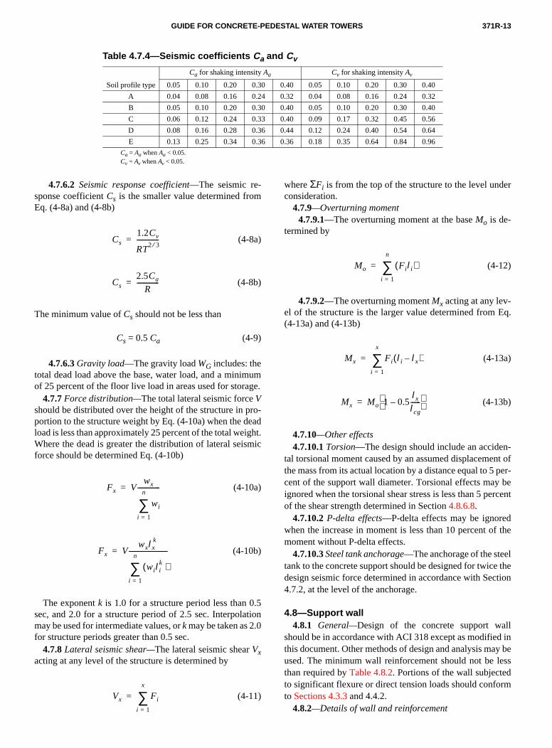
Table 4.7.4—Seismic coefficients Ca and Cv
Soil profile type
Ca for shaking intensity Aa Cv for shaking intensity Av
0.05 0.10 0.20 0.30 0.40 0.05 0.10 0.20 0.30 0.40
A 0.04 0.08 0.16 0.24 0.32 0.04 0.08 0.16 0.24 0.32
B 0.05 0.10 0.20 0.30 0.40 0.05 0.10 0.20 0.30 0.40
C 0.06 0.12 0.24 0.33 0.40 0.09 0.17 0.32 0.45 0.56
D 0.08 0.16 0.28 0.36 0.44 0.12 0.24 0.40 0.54 0.64
E 0.13 0.25 0.34 0.36 0.36 0.18 0.35 0.64 0.84 0.96
Ca = Aa when Aa < 0.05.Cv = Av when Av < 0.05.
uge
roeaghmi
.5tio
er
Eq.
n-nt of per- bercent
df the
l thetion
lld iny beessdrm
4.7.6.2 Seismic response coefficient—The seismic re-sponse coefficient Cs is the smaller value determined fromEq. (4-8a) and (4-8b)
(4-8a)
(4-8b)
The minimum value of Cs should not be less than
Cs = 0.5 Ca (4-9)
4.7.6.3 Gravity load—The gravity load WG includes: thetotal dead load above the base, water load, and a minimof 25 percent of the floor live load in areas used for stora
4.7.7 Force distribution—The total lateral seismic force Vshould be distributed over the height of the structure in pportion to the structure weight by Eq. (4-10a) when the dload is less than approximately 25 percent of the total weiWhere the dead is greater the distribution of lateral seisforce should be determined Eq. (4-10b)
(4-10a)
(4-10b)
The exponent k is 1.0 for a structure period less than 0sec, and 2.0 for a structure period of 2.5 sec. Interpolamay be used for intermediate values, or k may be taken as 2.0for structure periods greater than 0.5 sec.
4.7.8 Lateral seismic shear—The lateral seismic shear Vxacting at any level of the structure is determined by
(4-11)
Cs1.2Cv
RT2 3⁄--------------=
Cs2.5Ca
R--------------=
Fx Vwx
wi
i 1=
n
∑--------------=
Fx Vwxlx
k
wi lik( )
i 1=
n
∑-------------------------=
Vx Fi
i 1=
x
∑=
m.
-dt.c
n
where ΣFi is from the top of the structure to the level undconsideration.
4.7.9—Overturning moment4.7.9.1—The overturning moment at the base Mo is de-
termined by
(4-12)
4.7.9.2—The overturning moment Mx acting at any lev-el of the structure is the larger value determined from (4-13a) and (4-13b)
(4-13a)
(4-13b)
4.7.10—Other effects4.7.10.1 Torsion—The design should include an accide
tal torsional moment caused by an assumed displacemethe mass from its actual location by a distance equal to 5cent of the support wall diameter. Torsional effects mayignored when the torsional shear stress is less than 5 peof the shear strength determined in Section 4.8.6.8.
4.7.10.2 P-delta effects—P-delta effects may be ignorewhen the increase in moment is less than 10 percent omoment without P-delta effects.
4.7.10.3 Steel tank anchorage—The anchorage of the steetank to the concrete support should be designed for twicedesign seismic force determined in accordance with Sec4.7.2, at the level of the anchorage.
4.8—Support wall4.8.1 General—Design of the concrete support wa
should be in accordance with ACI 318 except as modifiethis document. Other methods of design and analysis maused. The minimum wall reinforcement should not be lthan required by Table 4.8.2. Portions of the wall subjecteto significant flexure or direct tension loads should confoto Sections 4.3.3 and 4.4.2.
4.8.2—Details of wall and reinforcement
Mo Fi li( )i 1=
n
∑=
Mx Fi li lx–( )i 1=
x
∑=
Mx Mo 1 0.5lx
lcg
------– =
371R-14 MANUAL OF CONCRETE PRACTICE
or
r).
haonior
ion
e
orte;
4.8.2.1 Minimum wall thickness—Wall thickness hshould not be less than 8 in. (200 mm). The thickness h is thestructural thickness, exclusive of any rustications, flutingother architectural relief.
4.8.2.2 Specified compressive strength—The specifiedcompressive strength of concrete should not be less thanquired in Section 3.2.2.2 nor greater than 6000 psi (41 MPa
4.8.2.3 Reinforcement—Wall reinforcement should con-form to Table 4.8.2. Not more than 60 percent nor less t50 percent of the minimum reinforcement in each directispecified in Table 4.8.2 should be distributed to the exterface, and the remainder to the interior face.
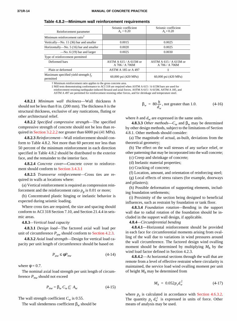
Table 4.8.2—Minimum wall reinforcement requirements
Reinforcement parameterSeismic coefficient
Av < 0.20Seismic coefficient
Av • 0.20
Minimum reinforcement ratio†
Vertically—No. 11 (36) bar and smaller 0.0015 0.0025
Horizontally—No. 5 (16) bar and smaller 0.0020 0.0025
—No. 6 (19) bar and larger 0.0025 0.0030
Type of reinforcement permitted
Deformed bars ASTM A 615 / A 615M orA 706 / A 706M
ASTM A 615 / A 615M orA 706 / A 706M
Plain or deformed ASTM A 185 or A 497 ‡
Maximum specified yield strength fypermitted
60,000 psi (420 MPa) 60,000 psi (420 MPa)
† Minimum reinforcement ratio applies to the gross concrete area.‡ Mill tests demonstrating conformance to ACI 318 are required when ASTM A 615 / A 615M bars are used for
reinforcement resisting earthquake-induced flexural and axial forces. ASTM A 615 / A 615M, ASTM A 185, andASTM A 497 are permitted for reinforcement resisting other forces, and for shrinkage and temperature steel.
in
is
ouis
n
-
l;ys
d-
al
-
l-dg
eisnit
r
4.8.2.4 Concrete cover—Concrete cover to reinforce-ment should conform to Section 3.4.3.1
4.8.2.5 Transverse reinforcement—Cross ties are re-quired in walls at locations where:
(a) Vertical reinforcement is required as compression reforcement and the reinforcement ratio pg is 0.01 or more;
(b) Concentrated plastic hinging or inelastic behavior expected during seismic loading.
Where cross ties are required, the size and spacing shconform to ACI 318 Section 7.10, and Section 21.4.4 in semic areas.
4.8.3—Vertical load capacity
4.8.3.1 Design load—The factored axial wall load perunit of circumference Puw should conform to Section 4.2.3.
4.8.3.2 Axial load strength—Design for vertical load ca-pacity per unit length of circumference should be based o
Puw ≤ φPnw (4-14)
where φ = 0.7. The nominal axial load strength per unit length of circum
ference Pnw should not exceed
Pnw = βw Cw fc′ Aw (4-15)
The wall strength coefficient Cw is 0.55.
The wall slenderness coefficient β should be
we-
n
-
ld-
, not greater than 1.0. (4-16)
where h and dw are expressed in the same units.4.8.3.3 Other methods—Cw and βw may be determined
by other design methods, subject to the limitations of Sect4.8.1. Other methods should consider:
(a) The magnitude of actual, as-built, deviations from ththeoretical geometry;
(b) The effect on the wall stresses of any surface relief, other patterning that may be incorporated into the wall concre
(c) Creep and shrinkage of concrete;(d) Inelastic material properties;(e) Cracking of concrete;(f) Location, amount, and orientation of reinforcing stee(g) Local effects of stress raisers (for example, doorwa
and pilasters);(h) Possible deformation of supporting elements, inclu
ing foundation settlements;(i) Proximity of the section being designed to benefici
influences, such as restraint by foundation or tank floor.4.8.3.4 Foundation rotation—Bending in the support
wall due to radial rotation of the foundation should be included in the support wall design, if applicable.
4.8.4—Circumferential bending4.8.4.1—Horizontal reinforcement should be provided
in each face for circumferential moments arising from ovaling of the wall due to variations in wind pressures arounthe wall circumference. The factored design wind ovallinmoment should be determined by multiplying Mh by thewind load factor defined in Section 4.2.3.
4.8.4.2—At horizontal sections through the wall that arremote from a level of effective restraint where circularity maintained, the service load wind ovalling moment per uof height Mh may be determined from
(4-17)
where pz is calculated in accordance with Section 4.6.3.2.The quantity pz dw
2 is expressed in units of force. Othemeans of analysis may be used.
βw 80 hdw
------=
Mh 0.052pzdw2=
371R-15GUIDE FOR CONCRETE-PEDESTAL WATER TOWERS
to
beori
12.5..5.
sg is
byg arcedinver
s reerttica
-an
reil to
halrag
lenrdallec
ct en
d- anothiveiladd
Th
ingve
t
thealentc-
ssrm
t of
tic
ns
-
byandontive
l toear
nsred
al
e
4.8.4.3—The wind ovalling moment Mh may be consid-ered to vary linearly from zero at a diaphragm elevationthe full value at a distance 0.5 dw from the diaphragm.
4.8.5—Openings in walls4.8.5.1—The effects of openings in the wall should
considered in the design. Wall penetrations having a hzontal dimension of 3 ft (0.9 m) or less and a height of hor less may be designed in accordance with Section 4.8Otherwise, the design should conform to Sections 4.8through 4.8.5.5.
4.8.5.2 Simplified method—Where detailed analysis inot required, minimum reinforcement around the openinthe larger amount determined by:
(a) Vertical and horizontal reinforcement interrupted the opening should be replaced by reinforcement havinarea not less than 120 percent of the interrupted reinfoment, half placed each side of the opening, and extenpast the opening a distance not less than half the transopening dimension;
(b) An area each side of the opening equal to 0.75bd shouldbe evaluated for vertical load capacity, and reinforced aquired. The load acting on this area should be half the vcal force interrupted by the opening plus the average verload in the wall at mid-height of the opening.
4.8.5.3 Effective column—The wall adjacent to an opening should be designed as a braced column in accordwith ACI 318 and the following:
(a) Each side of the opening should be designed as aforced concrete column having an effective width equathe smaller of 5h, 6 ft (1.8 m), or 0.5bd;
(b) The effective column should be designed to carry the vertical force interrupted by the opening plus the avevertical load in the wall at mid-height of the opening;
(c) The effective unsupported column length kl should notbe less than 0.85hd;
(d) The effective columns should be analyzed by the sder column procedures of ACI 318 and reinforced accoingly with bars on the inside and outside faces of the wTransverse reinforcement should conform to ACI 318 Stion 7.10, and Section 21.4.4 in seismic areas;
(e) The effective column should be checked for the effeof vehicle impact if the opening is to be used as a vehicletrance through the support wall.
4.8.5.4 Pilasters—Monolithic pilasters may be used ajacent to openings. Such pilasters should extend abovebelow the opening a sufficient distance to effect a smotransition of forces into the wall without creating excesslocal stress concentrations. The transition zone where pters are terminated should be thoroughly analyzed and ational reinforcement added if required for local stresses. reinforcement ratio pg should not be less than 0.01.
4.8.5.5 Horizontal reinforcement—Additional horizontalreinforcement should be provided above and below openin accordance with Eq. (4-18), and should be distributed oa height not exceeding 3h
(4-18)As0.14Puwbd
φfy
-------------------------=
-
2.3
n-gse
-i-l
ce
n-
fe
--.-
s-
d
s-i-e
sr
where φ = 0.9. Puw applies at the level of the reinforcemenbeing designed. The quantity puwbd is expressed in lb (N).The reinforcement yield strength fy used in Eq. (4-18) shouldnot exceed 60,000 psi (420 MPa).
4.8.5.6 Development of reinforcement—Additional rein-forcement at openings is to be fully developed beyond opening in accordance with ACI 318. Additional horizontreinforcement should project at least half a developmlength beyond the effective column or pilaster width of Setions 4.8.5.3 or 4.8.5.4.
4.8.5.7 Local effects below openings—Where the com-bined height of wall and foundation below the opening is lethan one-half the opening width the design should confoto Section 4.11.6.6.
4.8.6—Shear design
4.8.6.1 Radial shear—Design of the concrete supporwall for radial shear forces should conform to Chapter 11ACI 318.
4.8.6.2 In-plane shear—Design of the concrete supporwall for in-plane shear forces caused by wind or seismforces should conform to the requirements of Sectio4.8.6.3 through 4.8.6.10.
4.8.6.3 Design forces—The shear force Vu and simulta-neous factored moment Mu should be obtained from the lateral load analysis for wind and seismic forces.
4.8.6.4 Shear force distribution—The shear force distri-bution in the concrete support wall should be determineda method of analysis that accounts for the applied loads structure geometry. The simplified procedure of Secti4.8.6.5 may be used when the ratio of openings to effecshear wall width ψ does not exceed 0.5.
4.8.6.5 Shear force—The shear force Vu may be consid-ered to be resisted by two equivalent shear walls parallethe direction of the applied load. The length of each shwall should not exceed 0.78dw. The shear force Vuw actingon an equivalent shear wall should not be less than:
(a) In sections of the wall without openings or sectiowith openings symmetric about the centerline the factoshear force Vuw assigned to each shear wall is
Vuw = 0.5 Vu (4-19)
(b) In sections of the wall with openings not symmetricabout the centerline
(4-20)
where
bx is the cumulative width of openings in the effectivshear wall width 0.78dw. The dimensions bx and dw are ex-pressed in in. (mm).
Vuw 0.5Vu 1 ψ2 ψ–-------------+
=
ψbx
0.78dw
----------------=
371R-16 MANUAL OF CONCRETE PRACTICE
e
.
r
ar
.0;
/4;
cur- andent
ation-en-
mic
e-
ed., thee
tetank
s the the
ldkated
edec-
e that andalcu-dulus
eachaly-ion
tion
e-n of
ludedth oio
(us- be0
)
erac-
thanorce-ent
tion
teele tnd
4.8.6.6 Shear area—The effective horizontal concretwall area Acv resisting the shear force Vuw should not begreater than
Acv = 0.78 (1 - ψ) dw h (4-21)
where the dimensions of dw and h are expressed in in(mm).
4.8.6.7 Maximum shear—The distributed shear Vuwshould not exceed:
(a) in in.-lb units [ in SI units[when Eq. (4-19) controls, and
(b) in in.-lb units [ in SI units]when Eq. (4-20) controls.
4.8.6.8 Shear strength—Design for in-plane sheashould be based on
Vuw ≤ φVn (4-22)
where φ = 0.85.The nominal shear strength Vn should not exceed the she
force calculated from
(4-23)
where
but not less than 2.0 nor greater than 3
in.-lb units.
but not less than 1/6 nor greater than 1
SI units.
Mu and Vu are the total factored moment and shear ocring simultaneously at the section under consideration,ρh is the ratio of horizontal distributed shear reinforcemon an area perpendicular to Acv.
4.8.6.9 Design location—The nominal shear strength Vnshould be determined at a distance above the foundequal to the smaller of 0.39 dw or the distance from the foundation to mid-height of the largest opening, or set of opings with the largest combined ψ.
4.8.6.10 Reinforcement—Minimum reinforcementshould conform to Table 4.8.2. In regions of high seisrisk, reinforcement should also conform to the following:
(a) When Vuw exceeds in in.-lb units (in SI units) the minimum horizontal and vertical reinforcment ratios should not be less than 0.0025.
(b) When Vuw exceeds in in.-lb units (in SI units) two layers of reinforcement should be provid
(c) Where shear reinforcement is required for strengthvertical reinforcement ratio ρv should not be less than thhorizontal reinforcement ratio ρh.
4.9—Tank floors4.9.1—General
4.9.1.1 Scope—This section covers design of concreflat slab and dome floors of uniform thickness used as
8 fc′ Acv 2 3⁄( ) fc′ Acv
10 fc′ Acv 5 6⁄( ) fc′ Acv
Vn αc fc′ ρh fy+( )Acv=
αc 62.5Mu
Vudw
---------------–=
αc 0.50.21Mu
Vudw
------------------–=
fc′ Acv fc′ Acv 12⁄
2 fc′ Acv fc′ Acv 6⁄
floors, and suspended steel floors. Section 4.10 discusseinteraction effects of the concrete support structure andstorage tank that should be considered in the design.
4.9.1.2 Loads—The loads and load combinations shouconform to Sections 4.2.3 and 4.2.4. Loads acting on the tanfloor are distributed dead and water loads, and concentrloads from the access tube, piping and other supports.
4.9.2—Flat slab floors4.9.2.1 Design—Concrete slab floors should be design
in accordance with ACI 318, except as modified here. Spified compressive strength of concrete fc′ should not be lessthan required in Section 3.2.2.2.
4.9.2.2 Slab stiffness—The stiffness of the slab should bsufficient to prevent rotation under dead and water loadscould cause excessive deformation of the attached wallsteel tank elements. The stiffness of the slab should be clated using the gross concrete area, and one-half the moof elasticity of concrete.
4.9.2.3 Minimum reinforcement—Reinforcement shouldnot be less than 0.002 times the gross concrete area indirection. Where tensile reinforcement is required by ansis the minimum reinforcement should conform to Sect4.3.3.
4.9.2.4 Crack control—Distribution of tension rein-forcement required by analysis should conform to Sec4.4.2.
4.9.3—Dome floors4.9.3.1 Design—Concrete dome floors should be d
signed on the basis of elastic shell analysis. Consideratioedge effects that cause shear and moment should be incin the analysis and design. Specified compressive strengfconcrete fc′ should not be less than required in Sectn3.2.2.2 nor greater than 5000 psi (34 MPa).
4.9.3.2 Thickness—The minimum thickness h of a uni-form thickness dome should be computed by Eq. (4-24) ing any consistent set of units). Buckling effects shouldconsidered when the radius to thickness ratio exceeds 10
not less than 8 in. (200 mm) (4-24
where wu and fc′ are expressed in the same units, and h andRd are expressed in in. (mm).
The factored distributed wu is the mean dead and watload (Load Combination U1.1). The strength reduction ftor f is 0.7.
4.9.3.3 Minimum reinforcement—Reinforcement areaon each face in orthogonal directions should not be less0.002 times the gross concrete area. Where tensile reinfment is required by analysis the minimum reinforcemshould conform to Section 4.3.3.
4.9.3.4 Crack control—Distribution of tension rein-forcement required by analysis should conform to Sec4.4.2.
4.9.4—Suspended steel floorsSteel floor tanks utilize a suspended membrane s
floor, generally with a steel skirt and grouted base platotransfer tank loads to the concrete support structure, aa
h 1.5Rdwu
φfc′---------=

371R-17GUIDE FOR CONCRETE-PEDESTAL WATER TOWERS
ign, basig
r-
sandtank
rtac-face10.
ered
l re
ceead
on-ran
onting
dif-
por
ds.-ccu The
ssoribu
rma
im-low- be
tancens inlysis
ingsignheart ef-
irect
eve ate toich-
na- fornk
-sid-
ruc-f the
kirt and
ank
ll rein-ads
ide.t atessrete
are
e
e
ent-tank
Thelate be
steel compression ring to resist internal thrust forces. Desof suspended steel floors, and associated support skirtsplates, and compression rings is part of the steel tank de(Section 4.1.3).
4.10—Concrete-to-tank interface4.10.1—General
4.10.1.1 Scope—This section covers design of the inteface region of concrete-pedestal elevated tanks.
4.10.1.2 Interface region—The interface region includethose portions of the support wall, tank floor, ringbeam, steel tank affected by the transfer of forces from the floor and steel tank to the support wall.
4.10.1.3 Details—The details at the top of the suppowall are generally proprietary and differ from one manufturer to another. The loads and forces acting at the interand specific requirements are covered in Sections 4.through 4.10.5.
4.10.2—Design considerations 4.10.2.1 Load effects—The following load effects in
combination with dead and live loads should be considin design of the interface region:
(a) Loading caused by varying water level;(b) Seismic and wind forces that cause unsymmetrica
actions at the interface region;(c) Construction loads and attachments that cause con
trated loads or forces significantly different than the dand water loads;
(d) Short and long-term translation and rotation of the ccrete at the interface region, and the effect on the membaction of the steel tank;
(e) Eccentricity of loads, where the point of applicatiof load does not coincide with the centroid of the resiselements;
(f) Effect of restrained shrinkage and temperature ferentials;
(g) Transfer of steel tank loads to the concrete supstructure;
(h) Anchorage attachments when required for uplift loa4.10.2.2 Analysis—Analysis should be by finite differ
ence, finite element, or similar analysis programs that arately model the interaction of the intersecting elements.analysis should recognize:
(a) The three-dimensional nature of the problem;(b) The non-linear response and change in stiffness a
ciated with tension and concrete cracking, and the redisttion of forces that occur with stiffness changes;
(c) The effect of concrete creep and shrinkage on defotions at the interface;
(d) The sensitivity of the design to initial assumptions, perfections, and construction tolerances. Appropriate alance for variations arising from these effects shouldincluded in the analysis.
4.10.3—Dome floors4.10.3.1 Design considerations—The interface region
should be analyzed for in-plane axial forces, radial and gential shear, and moment for all loading conditions. Ectricity arising from geometry and accidental imperfectionthe construction process should be included in the ana
sen
,3
-
n-
e
t
-
--
-
--
.
Various stages of filling, and wind and seismic overturneffects should be considered when determining the deloads. Particular attention should be given to the radial sand moment in shell elements caused by edge restrainfects.
4.10.3.2 Ringbeam compression—The maximum ser-vice load compression stress in the ringbeam due to dhorizontal thrust forces should not exceed 0.30fc′ .
4.10.3.3 Fill concrete—Concrete used to connect thsteel tank to the concrete support structure should haspecified compressive strength not less than the concrewhich it connects or the design compressive strength, whever is greater.
4.10.4—Slab floorsThe support wall, tank floor, and steel tank should be a
lyzed for in-plane axial forces, radial shear, and momentall loading conditions. The degree of fixity of the steel tato the tank floor should be considered.
4.10.5—Suspended steel floors4.10.5.1 Design considerations—The analysis and de
sign of the concrete support element should include coneration of the following loading effects:
(a) Vertical loads not centered on the wall due to consttion inaccuracies causing shear and moment at the top owall. Non-symmetrical distribution of eccentricities;
(b) Horizontal shear loads caused by an out of plumb splate, or temperature differences between the steel tankconcrete wall;
(c) Transfer of wind and seismic forces between the tand concrete support;
(d) Local instability at the top of the wall.4.10.5.2 Support wall—The area near the top of the wa
must have adequate shear strength and be adequatelyforced for the circumferential moments caused by the loin Section 4.8.4.
4.10.5.3 Concrete support for base plates—The designcenterline of the support wall and steel skirt should coincA concrete ringbeam having a nominal width and heighleast 8 in. (200 mm) greater than the support wall thicknh is recommended for support of base plates. The concringbeam may be omitted when the following conditions met:
(a) The wall thickness h is equal to or greater than thwidth determined by
h = bp + 0.004dw + be (4-25)
where all dimensions are expressed in in. (mm).The edge distance term be should conform to Section
4.10.5.4, and the effective base plate width bp to Section4.10.5.5. The term 0.004dw is the diameter tolerance of thwall in Section 3.6.1(a).
(b) Special construction control measures are implemed to ensure that the diameter and curvature of steel matches the concrete construction.
(c) The as-built condition is checked and documented. radial deviation of the steel skirt and effective base pcenterlines from the support wall centerline should notgreater than 10 percent of the support wall thickness h. The
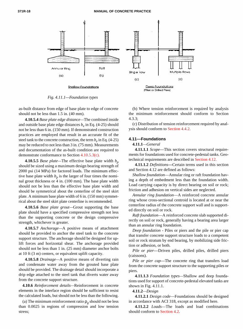
371R-18 MANUAL OF CONCRETE PRACTICE
ret
tio the
en to
th oc-
i-idthankiret-.
e lessiv
tretr upedolt
late wa
sising
ion
sision
al-
e-Geo-
n
-dth.ck;
rr theort-
i-rger
petentic-
ds or
-s are
d
s
as-built distance from edge of base plate to edge of concshould not be less than 1.5 in. (40 mm).
4.10.5.4 Base plate edge distance—The combined insideand outside base plate edge distances be in Eq. (4-25) shouldnot be less than 6 in. (150 mm). If demonstrated construcpractices are employed that result in an accurate fit ofsteel tank to the concrete construction, the term be in Eq. (4-25)may be reduced to not less than 3 in. (75 mm). Measuremand documentation of the as-built condition are requireddemonstrate conformance to Section 4.10.5.3(c).
4.10.5.5 Base plate—The effective base plate width bpshould be sized using a maximum design bearing streng2000 psi (14 MPa) for factored loads. The minimum effetive base plate width bp is the larger of four times the nomnal grout thickness or 4 in. (100 mm). The base plate wshould not be less than the effective base plate width should be symmetrical about the centerline of the steel splate. A minimum base plate width of 6 in. (150 mm) symmrical about the steel skirt plate centerline is recommended
4.10.5.6 Base plate grout—Grout supporting the basplate should have a specified compressive strength notthan the supporting concrete or the design compresstrength, whichever is greater.
4.10.5.7 Anchorage—A positive means of attachmenshould be provided to anchor the steel tank to the concsupport structure. The anchorage should be designed folift forces and horizontal shear. The anchorage providshould not be less than 1 in. (25 mm) diameter anchor bat 10 ft (3 m) centers, or equivalent uplift capacity.
4.10.5.8 Drainage—A positive means of diverting rainand condensate water away from the grouted base pshould be provided. The drainage detail should incorporadrip edge attached to the steel tank that diverts water afrom the concrete support structure.
4.10.6 Reinforcement details—Reinforcement in concreteelements in the interface region should be sufficient to rethe calculated loads, but should not be less than the follow
(a) The minimum reinforcement ratio ρg should not be lessthan 0.0025 in regions of compression and low tensstress;
e
n
ts
f
dt
se
e-
s
teay
(b) Where tension reinforcement is required by analythe minimum reinforcement should conform to Sect4.3.3;
(c) Distribution of tension reinforcement required by anysis should conform to Section 4.4.2.
4.11—Foundations4.11.1—General
4.11.1.1 Scope—This section covers structural requirments for foundations used for concrete-pedestal tanks. technical requirements are described in Section 4.12.
4.11.1.2 Definitions—Certain terms used in this sectioand Section 4.12 are defined as follows:
Shallow foundation—Annular ring or raft foundation having a depth of embedment less than the foundation wiLoad carrying capacity is by direct bearing on soil or rofriction and adhesion on vertical sides are neglected.
Annular ring foundation—A reinforced concrete annularing whose cross-sectional centroid is located at or neacenterline radius of the concrete support wall and is supped directly on soil or rock.
Raft foundation—A reinforced concrete slab supported drectly on soil or rock, generally having a bearing area lathan an annular ring foundation.
Deep foundation - Piles or piers and the pile or pier cathat transfer concrete support structure loads to a compsoil or rock stratum by end bearing, by mobilizing side frtion or adhesion, or both.
Pile or pier—Driven piles, drilled piles, drilled piers(caissons).
Pile or pier cap—The concrete ring that transfers loafrom the concrete support structure to the supporting pilepiers.
4.11.1.3 Foundation types—Shallow and deep foundations used for support of concrete-pedestal elevated tankshown in Fig. 4.11.1.
Fig. 4.11.1—Foundation types
t.
4.11.2—Design4.11.2.1 Design code—Foundations should be designe
in accordance with ACI 318, except as modified here.4.11.2.2 Loads—The loads and load combination
should conform to Section 4.2.

371R-19GUIDE FOR CONCRETE-PEDESTAL WATER TOWERS
-ltinere b tovice
ting n
e
ingonpac- thn a
d ode.
e an
- caas
focaruc
l de
anare
ultsejec of
se byothier
that
ns.ere
-t1.1,xi-
smine
-ier
on-n toing
bu-
reteon
-ent
hichthe
a- by
e-hni-
;ter,
tal
to
sist
ech- in
to
4.11.3 Overturning—The foundation should be of sufficient size and strength to resist overturning forces resufrom wind, seismic, and differential settlement loads. Whhigh groundwater occurs, the effects of buoyancy shouldincluded. The stability ratio (ratio of the resisting momentoverturning moment) should be greater than 1.5 for serload forces.
4.11.3.1 Resisting gravity load—The gravity service loadPs resisting overturning is the dead load D for wind loading,and dead plus water loads D + F for seismic loading.
4.11.3.2 Shallow foundations—The resisting moment isthe product of the gravity service loads Ps and the distancefrom the foundation centerline to the centroid of the resiscontact pressure. The resisting contact pressure shouldexceed the ultimate bearing capacity qr defined in Section4.12.4.
4.11.3.3 Deep foundations—The resisting moment is thproduct of the gravity service loads Ps and the distance fromthe foundation centerline to the centroid of the resistgroup of piles or drilled piers. The maximum load acting a deep foundation unit should not exceed the ultimate caity Qr defined in Section 4.12.5. Where piles or piers are capable of resisting tension loads and are connected tosuperstructure, the tension capacity may be considered isessing the stability ratio.
4.11.4—Shallow foundations4.11.4.1 Annular ring foundation—Torsional effects and
biaxial bending should be considered when the centroithe footing and the centerline of the wall do not coinciThe footing may be designed as a one-way beam elemthat is a sector of an annulus when the centroids coincidethe circumferential biaxial effects may be excluded.
4.11.4.2 Raft foundation—The portion inside the concrete support wall is designed as a two-way slab and thetilever portion may be designed as a one-way strip, or continuation of the two-way interior slab.
4.11.5—Deep foundations4.11.5.1 Structural design—The structural design o
piles or piers should be in accordance with national and lbuilding codes. Recommendations for design and consttion of drilled piers are found in ACI 336.3R.
4.11.5.2 Lateral load effects on piles or piers—The ef-fect of lateral loads should be considered in the structurasign of piles or piers.
4.11.5.3 Lateral load effects on pile or pier caps—Thepile or pier cap should be designed for the shear, torsion,bending moments that occur when piles or drilled piers subject to lateral loads.
4.11.5.4 Lateral seismic loads—Piling should be de-signed to withstand the maximum imposed curvature resing from seismic forces for freestanding piles, in loogranular soils and Soil Profile Types E and F. Piles subto such deformation should conform to Section 9.4.5.3ASCE 7.
4.11.6—Design details4.11.6.1 Load transfer—Forces and moments at the ba
of concrete wall should be transferred to the foundationbearing on concrete, by reinforcement and dowels, or bThe connection between the pile or pier cap and piles or p
g
e
ot
-
es-
f
ntd
n-a
l-
-
d
-
t
.s
should be designed for bearing, shear, and uplift forces occur at this location.
4.11.6.2 Development of reinforcement—Flexural steelshould be checked for proper development at all sectioHooks may be used to develop footing reinforcement whthe footing extension is relatively small.
4.11.6.3 Serviceability—The service load tension reinforcement steel stress fs at sections of maximum momenshould not exceed 30,000 psi (205 MPa) for load case Sdead and water loads only. Alternatively, sections of mamum moment should conform to the requirements of Section4.4.2.
4.11.6.4 Sloped foundations—When tapered top surfaceare used, actual footing shape should be used to detershear and moment capacities.
4.11.6.5 Concrete cover—The actual clear distance between the edge of foundation and edge of a pile or pshould not be less than 3 in. (75 mm) after installation.
4.11.6.6 Support wall openings—The local effects atlarge openings in the concrete support wall should be csidered when the distance from the top of the foundatiothe bottom of the opening is less than one-half the openwidth. The foundation should be designed for the redistrition of loads across the unsupported opening width.
4.11.6.7 Seismic design details—Where design for seis-mic loads is required, details of concrete piles and concfilled piles should conform to the requirements of SectiA9.4.4.4 of ASCE 7.
4.12—Geotechnical recommendations4.12.1—General
4.12.1.1 Scope—This section identifies the minimum requirements related to foundation capacity and settlemlimits.
4.12.1.2 Geotechnical investigation—A subsurface in-vestigation should be made to the depth and extent to wthe tank foundation will significantly change the stress in soil or rock, or to a depth and extent that provides informtion to design the foundation. The investigation should bea qualified design professional.
The following information should be provided to the dsign professional responsible for conducting the geoteccal investigation:
(a) Tank configuration, including support wall diameter(b) Gravity loads acting on the foundation: dead, wa
and live loads;(c) Wind and seismic overturning moments and horizon
shear forces acting at top of foundation;(d) Minimum foundation depth for frost penetration or
accommodate piping details;(e) Whether deep foundation units are required to re
tension uplift forces.4.12.1.3 Foundation requirements—The design of
foundations should be based on the results of the geotnical investigation. The foundation should be configuredaccordance with the requirements of Sections 4.12.2through 4.12.5. Structural components should conformSection 4.11.

371R-20 MANUAL OF CONCRETE PRACTICE
- th be to
m).dtionhetotathen-
:)
0.q.
lks th
to a
uldeon
at. It
tor
pre
a-ne
dc-n;3
nd
bebl
p
e-edod- of
4.12.2 Foundation depth—Foundation depth should be below the extreme frost penetration depth, or as required byapplicable building code. A smaller foundation depth mayused if the foundation overlies material not susceptiblefrost action. The minimum depth should be 12 in. (300 m
4.12.3 Settlement limits—The combined foundation anconcrete support structure provide a very rigid constructhat will experience little or no out-of-plane settlement. Tsubsurface deformations that require consideration are settlement, and differential settlement causing tilting of structure. Typical long-term predicted settlement limits uder load combination S1.1, dead and full water load, are
Total settlement for shallow foundations: 1.5 in. (40 mmTotal settlement for deep foundations: 3/4 in. (20 mm)Tilting of the structure due to non-uniform settlement: 1/80Larger differential tilt is permitted when included in E
(4-1b). Maximum tilt should not exceed 1/300.Elevations for slabs on grade, driveways, and sidewa
should be selected to have positive drainage away fromstructure after long term settlements have occurred.
4.12.4 —Shallow foundations4.12.4.1 Ultimate bearing capacity—The ultimate bear-
ing capacity qr is the limiting pressure that may be appliedthe soil/rock surface by the foundation without causingshear failure in the material below the foundation. It shobe determined by the application of generally accepted gtechnical and civil engineering principles in conjunctiowith a geotechnical investigation.
4.12.4.2 Allowable bearing capacity—The allowablebearing capacity qa is the limiting service load pressure thmay be applied to the soil/rock surface by the foundationshould be the smaller value determined from:
(a) Permissible total and differential settlements;(b) Ultimate bearing capacity divided by a safety fac
not less than three. 4.12.4.3 Net bearing pressure—Ultimate or allowable
bearing pressure should be reported as the net bearing sure defined in Fig. 4.12.4.
Fig. 4.12.4—Net bearing pressure
-t iny o
r- ored
4.12.4.4 Foundation size—The size of shallow foundations should be the larger size determined for settlemenaccordance with Section 4.12.4.2 or the bearing capacitthe soil using the unfactored loads in Section 4.2.4.
e
l
e
-
s-
f
4.12.5—Deep foundations4.12.5.1 Ultimate capacity—The ultimate capacity of
piles or piers Qr should be based on a subsurface investigtion by a qualified geotechnical design professional, and oof the following:
(a) Application of generally accepted geotechnical ancivil engineering principles to determine the ultimate capaity of the tip in end bearing, and the side friction or adhesio
(b) Static load testing in accordance with ASTM D 114of actual foundation units;
(c) Other in-situ load tests that measure end bearing aside resistance separately or both;
(d) Dynamic testing of driven piles with a pile drivinganalyzer.
4.12.5.2 Allowable capacity—The allowable service loadcapacity Qa is the ultimate capacity Qr divided by a safetyfactor not less than shown in Table 4.12.5. It should notgreater than the load causing the maximum permissiesettlement.
4.12.5.3 Settlement and group effects—An estimate ofthe settlement of individual piles or piers and of the groushould be made by the geotechnical design professional.
4.12.5.4 Lateral load capacity—The allowable lateralload capacity of piles and drilled piers and corresponding dformation at the top of the pile or pier should be determinby the geotechnical design professional. The subgrade mulus or other soil parameters suitable for structural designthe pile or pier element should be reported.
4.12.5.5 Number of piles or drilled piers—The numberof piles or drilled piers should be the larger number detemined for settlement in accordance with Section 4.12.5.2for the resistance of the soil or rock using the unfactorloads in Section 4.2.4.
Table 4.12.5—Factor of safety for deep foundationsUltimate capacity in accordance
with SectionRecommended minimum
safety factor
4.12.5.1(a) 3.0
4.12.5.1(b) 2.0
4.12.5.1(c) 2.0
4.12.5.1(d) 2.5
371R-21GUIDE FOR CONCRETE-PEDESTAL WATER TOWERS
les be
en
nits
d-
duld
de
the
porthens to
rlopac
lies
tureen
voritio
sti
ls
recom, aionble
en-at isula- and
s,on-ts-lenttherelyer-
-on-
izeem
of
entside
ideuldnednts
ld ontheails
r
-
t-n.ttened be of
4.12.5.6 Spacing of piles or drilled piers—The minimumspacing between centers of driven piles should not be than 2.0 times the butt diameter. The following shouldconsidered when determining the spacing and arrangemof piles and drilled piers:
(a) The overlap of stress between pile or drilled pier uinfluencing total load capacity and settlement;
(b) Installation difficulties, particularly the effects on ajacent piles or drilled piers.
4.12.5.7 Number and arrangement of piles or drillepiers—The number and arrangement of piles or piers shobe such that the allowable capacity Qa is not exceeded whenthe foundation is subjected to the combined service loadsfined in Section 4.2.4.
4.12.6—Seismic requirements4.12.6.1 Site factor—In areas where Av ≥ 0.05 the geo-
technical design professional should classify and reportsoil type conforming Table 4.7.4.
4.12.6.2 Liquefaction potential—In areas where Av ≥0.05 the geotechnical design professional should rewhether or not there is a potential for soil liquefaction at site. Where soil liquefaction is possible, deep foundatiosoil improvement, or other means should be employedprotect the structure during an earthquake.
4.12.7—Special considerations4.12.7.1 Sloping ground—Where the foundation is on o
near sloping ground the effect on bearing capacity and sstability should be considered in determining bearing capity and foundation movements.
4.12.7.2 Geologic conditions—Geologic conditions suchas karst (sinkhole) topography, faults or geologic anomashould be identified and provided for in the design.
4.12.7.3 Swelling and shrinkage of soils—Where swell-ing or shrinkage movements from changes in soil moiscontent are encountered or known to exist, such movemshould be considered.
4.12.7.4 Expanding or deteriorating rock—Where rockis known to expand or deteriorate when exposed to unfaable environmental conditions or stress release, the condshould be provided for in the design.
4.12.7.5 Construction on fill—Acceptable soil types, andcompaction and inspection requirements should be invegated and specified when foundations are placed on fill.
4.12.7.6 Groundwater level changes—The effect oftemporary or permanent changes in groundwater levetyshould be investigated and provided for in the design.
CHAPTER 5—APPURTENANCES AND ACCESSORIES
5.1—General5.1.1 Scope—This chapter describes the appurtenances
quired for operation and maintenance, and accessories monly furnished with concrete-pedestal elevated tanksshown in Fig. 5.1. Items furnished at any given installatwill depend on the project documents and the applicabuilding code.
ap-odeoad
0ventect
5.1.2 Design—Design and detailing of accessories andpurtenances should conform to the applicable building cand state and federal requirements where applicable. L
s
t
-
t
,
e-
t
-n
-
--
s
,s
should not be less than those required by ASCE 7. Dimsions and sizes where shown are intended to indicate whcommonly used, and may not conform to codes and regtions in all cases because of differences between codesregulations and revision of these documents.
5.1.3 Personnel safety—The design and details of ladderstairways, platforms, and other climbing devices should cform to OSHA and applicable building code requiremenfor industrial structures. The design and use of anti-fall devices (cages and safe climb devices) should be compatibwith the climbing system to which they attach. Attachmeof ladders, stairways, platforms, and anti-fall devices to structure should be designed to mechanically fasten secuto the structure during the anticipated service life, considing the exposure of the attachment to the environment.
5.1.4 Galvanic corrosion—Dissimilar metals should beelectrically isolated to prevent galvanic corrosion.
5.2—Support wall access5.2.1 Exterior doors—One or more exterior doors are re
quired for access to the support wall interior, and should cform to the following:
(a) At least one personnel or vehicle door of sufficient sto permit moving the largest equipment or mechanical itthrough the support wall;
(b) Steel pipe bollards should be provided at the sidesvehicle door openings for impact protection;
(c) Doors at grade should have locking devices to prevunauthorized access to ladders and equipment located inthe support wall.
5.2.2 Painters’ access—A hinged or removable door at thetop of the support wall is required for access to the outspainters rigging from the upper platform. The opening shohave a least dimension of 24 in. (610 mm). It may be screeand louvered to satisfy all or part of the vent area requireme.
5.3—Ventilation5.3.1—Support wall vents
5.3.1.1 Location and number—The location and number ofvents for ventilation of the concrete support wall interior shouconform to state and local building code requirements basedoccupancy classification. A removable vent at the top of support wall may be used for access to the exterior rigging rlocated at the tank/pedestal intersection.
5.3.1.2 Description—Vents should be stainless steel oaluminum, and should have removable insect screens.
5.3.1.3 Access—Vents should be accessible from the interior ladders, platforms or floors.
5.3.2—Tank vent5.3.2.1 Location—The tank vent should be centrally loca
ed on the tank roof above the maximum weir crest elevatio5.3.2.2 Description—The vent consists of a suppor
frame, screened area and cap. The support should be fasto a flanged opening in the tank roof. The vent cap shouldprovided with sufficient overhang to prevent the entrancewind driven debris and precipitation. A minimum of 4 in. (10mm) should be provided between the roof surface and the cap. The vent should be provided with a bird screen. Ins

371R-22 MANUAL OF CONCRETE PRACTICE
Fig. 5.1—Typical accessories and appurtenances
able
kesurengowumeThet ca Ventherld b
fven
oofrt ofism
andres-
toces
l-
l;
screening should be provided when required by applicbuilding codes, health regulations, or project documents.
5.3.2.3 Capacity—The tank vent should have an intaand relief capacity sufficiently large that excessive presor vacuum will not be developed when filling or emptyithe tank at maximum flow rate of water. The maximum flrate of water exiting the tank should be based on an assbreak in the inlet/outlet at grade when the tank is full. overflow pipe should not be considered as a vent. Venpacity should be based on open area of screening used.should be designed to operate when frosted over or owise clogged, or adequate pressure/vacuum relief shouprovided.
5.3.3 Pressure/vacuum relief—A pressure/vacuum reliemechanism should be provided that will operate in the e
d
-ts-e
t
of tank vent failure. It should be located on the tank rabove the maximum weir crest elevation and may be pathe vent. Design of the pressure/vacuum relief mechanshould be such that it is not damaged during operation,that it returns to the normal position after relieving the psure differential.
5.4—Steel tank access5.4.1 General—Access from interior of the support wall
the tank roof and interior is provided by the appurtenandescribed below.
5.4.1.1 Materials—Materials should conform to the folowing:
(a) Ladders and platforms: painted or galvanized stee(b) Access tube: painted steel plate or pipe;

371R-23GUIDE FOR CONCRETE-PEDESTAL WATER TOWERS
teel
less
les
rackry ttubee atdde
ppu
;ith
singect
ld
ess
on be
tion foricesrms rai
e-4.2
eds.at
intepor m)
g oeas
fvidcat
me
c-gh
ubepediorast
etyuldnsroofchm)
lat-he in.
behe
onuld
e be
orrm
thely
ionible
gs
eess
de-rior
The
(c) Roof hatches and covers: painted or galvanized sor aluminum;
(d) Manholes: painted or galvanized steel, or stainsteel;
(e) Embedments: painted or galvanized steel, or stainsteel.
5.4.1.2 Attachment to steel tank—Attachment of laddersand other accessories to the steel tank should be with bets welded to the steel tank. Attachment of the accessothe brackets may be by welding or bolting. The access exterior should be reinforced where ladder brackets artached so that potential ice damage is confined to the laand bracket and not the access tube shell.
5.4.1.3 Attachment to concrete—The following methodsare commonly used for attachment of accessories and atenances to concrete:
(a) Embedded anchor bolts and threaded anchorages(b) Welding or bolting to embedment plates anchored w
headed studs;(c) Drilled anchors: expansion type and grouted type u
chemical adhesives. Only drilled anchors that can be insped or tested for proper installation should be used.
5.4.2—Ladders5.4.2.1 Location—Interior vertical access ladders shou
be provided at the following locations:(a) Grade to upper platform;(b) Upper platform to tank floor manhole;(c) Upper platform to steel tank roof (mounted on acc
tube interior);(d) Steel tank roof to steel tank interior floor (mounted
access tube exterior). In cold climates this ladder mayomitted to prevent damage from ice.
5.4.2.2 Fall protection—A safe climbing device shouldbe provided wherever cages or other means of fall protecare not provided. A safe climbing device is recommendedaccess tube ladders. Ladders with safe climbing devshould be continuous through intermediate or rest platfoso that personnel are not forced to disengage. Extensionmay be required at manhole openings.
5.4.3—Platforms and handrails5.4.3.1 Loads—Platforms and handrails should be d
signed for the minimum loads defined in Sections through 4.4 of ASCE 7, and the requirements of OSHA1 andthe applicable building code.
5.4.3.2 Platforms—Platforms should be provided at thfollowing locations, complete with handrails and toeboar
(a) An upper platform located below the tank floor thprovides access from the wall ladder to: the access tuberior ladder, the tank floor manhole, and the painters supwall access opening. A least platform dimension of 4 ft (1.2is recommended.
(b) Intermediate platforms are used for access to pipinequipment, as rest platforms, and with offset ladders. A lplatform dimension of 3 ft (0.9 m) is recommended.
5.4.3.3 Roof handrail—A handrail surrounding the roomanholes, vents, and other roof equipment should be proed. Where a handrail is not used or where equipment is loed outside the handrail, anchorage devices for the attachof safety lines should be provided.
,
s
-o
-r
r-
-
ls
-t
rt
--nt
5.4.4 Access tube—The access tube provides interior acess to the steel tank roof from the upper platform, throuthe water containing portion of the tank. The access tshould be not less than 42 in. (1.07 m) diameter, equipwith a hinged hatch cover with inside handle and interlocking device. The hatch opening size should have a ledimension of 24 in. (610 mm) or larger.
5.4.5 Steel tank roof openings—Roof openings should belocated above the overflow level at ladder locations. Safgrating, barricades, warning signs, or other protection shobe provided at roof openings to prevent entry at locatiowhere ladders are omitted. Hatches should be weatherpand equipped with a hasp to permit locking. Roof hatopenings should have a least dimension of 24 in. (610 mor larger.
5.4.6 Tank floor manhole—A manhole in the tank floorshould be provided which is accessible from the upper pform or from a ladder that extends from the platform to topening. It should have a least dimension of 24 in. to 30(610 to 760 mm).
5.5—Rigging devicesBar, tee rails, or other rigging anchorage devices should
provided for painting and maintenance of the structure. Tsafe load capacity for rigging devices should be shownconstruction drawings. Access to rigging attachments shobe provided.
5.5.1 Exterior rails—A continuous bar or tee rail near thtop of the exterior of the concrete support structure shouldprovided. The rail may be attached to the support wallsteel tank. Access to the rail is from the upper platfothrough a painters opening (Section 5.2.2).
5.5.2 Tank interior—Provision for painting the interior ofsteel tanks should be provided. Painters rails attached toroof or pipe couplings with plugs in the roof are commonused for rigging attachment.
5.5.3 Support wall interior—Rigging attachments shouldbe provided near the top of the support wall for inspectand maintenance of piping and equipment not accessfrom platforms or floors.
5.6—Above ground piping5.6.1 Materials—Steel and stainless steel pipe and fittin
may be used for above ground piping.5.6.1.1 Minimum thickness—Only steel pipe with a mini-
mum thickness of 1/4 in. (6.4 mm) should be used where pipis exposed to stored water inside the tank. Minimum thicknof pipe located outside the stored water area should be:
(a) Steel pipe without interior lining or coating: 1/4 in.(6.4 mm);
(b) Steel pipe with interior lining or coating: 3/16 in. (4.8 mm);(c) Stainless steel pipe: 12 gage (2.7 mm);
5.6.1.2 Interior linings or coatings—Where interior lin-ings or coatings are required, pipe components should betailed and field assembled so as not to damage the intelining or coating.
5.6.2—Inlet/outlet pipe5.6.2.1 Configuration—Usually a single inlet/outlet pipe
is used to connect the tank to the system water main.
371R-24 MANUAL OF CONCRETE PRACTICE
wn-r oththed o
t-s a
-Thew ontaltha
t/mo
andilityrad
-ettlen. A
ointmen be
tsigm) be
ons.te o
djec
Figot bn ofain-e in-ge.
ar-ss-rednot
e andld boveen
e.ldporrva
tion
e for
e line,ion.h a
inro-
theable00
-iceoads
ro-iater in
r theppli-met.suous
e de-
con-, areing.rade
faceouldc orcingm).
pipe extends through the tank floor and runs vertically doward to an expansion joint connected to a base elbow oer piping. Various configurations for piping outside support wall to the water system are used that depenfoundation details and climate considerations.
5.6.2.2 Sizing—The minimum diameter of the inlet/oulet pipe is based on acceptable losses due to system flowconsideration of freezing potential.
5.6.2.3 Support—Vertical pipe loads, including axial expansion joint forces, are supported at the tank floor. weight of water in the pipe is supported by the base elbopiping below the expansion joint. Pipe guides for horizosupport are attached to the support wall at intervals should not exceed 20 ft (6 m).
5.6.2.4 Expansion joint—The expansion joint in the inleoutlet pipe should be designed and constructed to accomdate any differential movement caused by settlementthermal expansion and contraction. The required flexibshould be provided by an expansion joint located near gin the vertical section of pipe.
5.6.2.5 Differential movement—Potential movement between the water main system and tank piping due to sment or seismic loads should be considered in the desigmechanical joint or coupling should be provided at the pof connection to the water main system unless no moveis expected. Additional couplings or special fittings mayused if differential movement is expected to be large.
5.6.2.6 Entrance details—Flush mounted inlet/outlepipe should have a removable silt stop at or below the delow water level that projects a minimum of 6 in. (150 mabove the tank floor liner. Inlet safety protection shouldprovided in accordance with applicable safety regulatiWhere no permanent protection is required a safety graplate should be provided during construction.
5.6.3—Overflow5.6.3.1 Configuration—The top of the overflow shoul
be located within the tank at the level required by the prodocuments and should run approximately as shown in5.1. The discharge should be designed such that it will nobstructed by snow or other objects. The horizontal rupipe below the tank floor should be sloped for positive drage. In cold climates the overflow may be located on thterior of the access tube if there is potential for ice dama
5.6.3.2 Sizing—The overflow pipe should be sized to cry the maximum design flow rate of the inlet pipe. Head loes from pipe, fittings, and exit velocity should be considein determining pipe diameter. The overflow pipe should be less than 4 in. (100 mm) diameter.
5.6.3.3 Entrance—The entrance to the overflow pipshould be designed for the maximum inlet pipe flow rate,should have a vortex prevention device. The design shoubased on the water level cresting within 6 in. (150 mm) abthe overflow level. A suitable weir should be provided whthe entrance capacity of the overflow pipe is not adequat
5.6.3.4 Support—Supports for the overflow pipe shoube designed for static, dynamic, and thermal loads. Supbrackets, guides and hangers should be provided at intenot exceeding 20 ft (6 m). The overflow and weir sec
-
n
nd
r
t
-
e
-
t
n
r
t.e
e
tls
within the steel tank may be attached to the access tubsupport.
5.6.3.5 Discharge—The overflow pipe should dischargonto a splash block at grade, or into a sump or a drainthat effectively removes water away from the foundatThe end of the overflow pipe should be covered witcoarse, corrosion resistant mesh or a flap valve.
5.6.4 Tank drain—An inlet/outlet pipe or a separate draline that is flush with the low point of the tank should be pvided to completely drain the tank.
5.7—Below ground piping and utilities5.7.1 Pipe cover—Pipe cover should be greater than
extreme frost penetration, or as required by the applicbuilding code. The minimum cover should be 24 in. (6mm).
5.7.2 Differential movement—Connecting piping and utilities should have sufficient flexibility to accommodate twthe predicted settlement or movement due to seismic lwithout damage.
5.8 Interior floors5.8.1 General—A concrete slab on grade should be p
vided inside the concrete wall. One or more intermedfloors above grade may be furnished when provided fothe original design.
5.8.1.1 Occupancy classification—Each portion of theinterior space should be classified according to its use ocharacter of its occupancy and the requirements of the acable building code for the type of occupancy should be
5.8.1.2 Posted live loads—The safe floor live loadshould be displayed on a permanent placard in a conspiclocation at each floor level.
5.8.2 Slabs-on-grade—Refer to ACI 302.1R for guidancon floor slab construction and ACI 360 for recommendedsign requirements.
5.8.2.1—Slabs on grade are usually designed as plain crete slabs where reinforcement, as well as joint spacingused to control cracking and to prevent cracks from openWhere project documents do not indicate how the slab on gwill be used, the values in Table 5.8.2 are recommended.
5.8.2.2 Details of reinforcement—Reinforcement shouldbe located approximately 2 in. (50 mm) below the top surof the slab. Slabs greater than 8 in. (200 mm) thick shhave two layers of reinforcement. Either welded wire fabrideformed bar reinforcement may be used. Maximum spaof wires or bars should not be greater than 18 in. (460 mReinforcement should be maintained in correct position by
Table 5.8.2—Minimum requirements for slabs on grade
DescriptionDoor opening widthless than 8 ft (2.4 m)
Door opening widthgreater than 8 ft (2.4 m)
Concrete strength: fc′ 3500 psi (24 MPa) 4000 psi (28 MPa)
Thickness 5 in. (125 mm) 6 in. (150 mm)
Reinforcement ratio 0.0018 0.0018
Note: Floors intended to be used for parking of heavy vehicles or similar loads should be designed for the specific loading anticipated

371R-25GUIDE FOR CONCRETE-PEDESTAL WATER TOWERS
enies
dm
so-ls,intx-ino-
6sackjoiini-o os- no
ldop
th b
ct-sit thna
r eor
steiat
leorsrm
d
theia
ho
eg
ould theoor.
ld
he m) by
ccessnt to
ntdingve
e theve theghtse of
rox-) re-or-rds.
iza-eir
for
m-
or-s
n-
t-
n-
r-
s
support chairs or concrete blocks. Additional reinforcemshould be provided at floor edges and other discontinuitas required by the design.
5.8.2.3 Joints—The following joint types are commonlyused and should conform to ACI 504R:
(a) Isolation joints—The floor slab should be separatestructurally from other elements of the structure to accomodate differential horizontal and vertical movements. Ilation joints should be provided at junctions with walcolumns, equipment or piping foundations, and other poof restraint. Isolation joints should be formed by setting epansion joint material prior to concrete placement. The jofiller should extend the full depth of the joint and not prtrude above the surface.
(b) Contraction joints—Joint spacing should be at 20 ft (m) maximum centers. Joints should be hand-tooled or cut to a depth of one-fourth to one-third times the slab thiness. Reinforcement should be continuous across the for slabs up to 70 ft (21 m) wide. For larger slabs the mmum reinforcement ratio should be increased by the ratithe slab width to 70 ft (21 m). Alternatively dowels with dicontinuous reinforcement can be provided at a spacingexceeding 70 ft (21 m).
5.8.2.4 Drainage—The surface of slabs-on-grade shouhave a minimum slope of 1 percent sloping to drains. Slto doorways where drains are not provided.
5.8.2.5 Subgrade—The suitability of in-situ and fill soilsfor supporting the slab on grade should be determined bygeotechnical design professional. Unsuitable soils shouldimproved or replaced. Any fill materials should be compaed to a density of 90 to 95 percent modified Proctor den(ASTM D 1557). Where expansive soils are encountered,recommendations of the geotechnical design professioshould be followed.
5.8.2.6 Structural floors—An isolated structural floorslab near grade may be required where compressible opansive soils are encountered. Design of structural floshould conform to ACI 318.
5.8.3 Intermediate floors—One or more floors abovegrade may be constructed for storage or other uses. Typicallythe structural system is a flat slab, or a beam and slab syattached to the support wall, and may include intermedcolumns.
5.8.3.1 Loads—Loads should conform to the applicabbuilding code, based on occupancy classification. Floused for storage should be designed for a minimum unifolive load of 125 lb/ft2 (6 kPa). The minimum design live loashould be 50 lb/ft2 (2.4 kPa).
5.8.3.2 Design and construction—Dead and live loadsfrom any intermediate floors should be accounted for in design of the support wall and foundation. Localized axloads, moments and shear due to beam end reactions sbe considered in the design of the support wall.
5.9—Electrical and lighting5.9.1 General—Electrical work should conform to the
governing applicable building code and other applicable rulations.
5.9.2—Lighting and receptacles
t,
-
s
t
w-nt
f
t
e
ee
yel
x-s
me
luld
-
5.9.2.1 Exterior—A single light should be providedabove each personnel and vehicle door. These lights shbe controlled by a single switch located on the interior ofsupport wall, adjacent to the open side of the personnel d
5.9.2.2 Interior—Interior lighting and receptacles shoube provided at the following locations:
(a) Base—Lights should be provided 8 ft (2.4 m) above tslab-on-grade at equal intervals not exceeding 30 ft (9along the support wall. These lights should be controlleda single switch located adjacent to the open side of the adoor. One convenience outlet should be provided adjacethe power distribution panel.
(b) Ladder/landing—Lights should be provided adjaceto the support wall access ladder at intervals not excee25 ft (8 m). The lower light should be at 8 ft (2.4 m) abothe slab and the top ladder light should be placed abovupper platform. A light should be provided 8 ft (2.4 m) aboeach intermediate platform. Lights should be provided attop and bottom of the interior access tube. These lishould be controlled by a single switch located at the basthe support wall access ladder.
5.9.3 Obstruction lighting—Obstruction lighting andmarking requirements depend on structure height and pimity to air traffic. The Federal Aviation Agency (FAAshould be contacted to determine if obstruction lighting isquired. Obstruction lighting should be of weathertight, crosion resistant construction, conforming to FAA standa
CHAPTER 6—REFERENCES6.1—Recommended references
The documents of various standards-producing organtions referred to in this document are listed below with thserial designation.
American Concrete InstituteACI 116R Cement and Concrete TerminologyACI 117 Standard Specifications for Tolerances
Concrete Construction and MaterialsACI 209R Prediction of Creep, Shrinkage, and Te
perature Effects in Concrete StructuresACI 211.1 Standard Practice for Selecting Prop
tions for Normal, Heavyweight, and MasConcrete
ACI 302.1R Guide for Concrete Floor and Slab Costruction
ACI 304R Guide for Measuring, Mixing, Transporing, and Placing Concrete
ACI 305R Hot Weather ConcretingACI 306R Cold Weather ConcretingACI 308 Standard Practice for Curing ConcreteACI 309R Guide for Consolidation of ConcreteACI 315 Details and Detailing of Concrete Rei
forcementACI 318 Building Code Requirements for Structu
al ConcreteACI 336.3R Design and Construction of Drilled PierACI 347R Guide to Formwork for ConcreteACI 360 Design of Slabs on Grade

371R-26 MANUAL OF CONCRETE PRACTICE
c-
d-
d-
d-
--
-
-
d
e-
e-
e
th
te
nf-
er
n
ng
ents,
orageteel
truc-ften
d as un-tails,, fre-ers,
n ac-e ex-tineoredrain-tiallyandon-ts the.2R.terialreteittle
ated
ctionfloorme-
less
efi-all
ACI 504R Guide to Sealing Joints in Concrete Strutures
American Society of Civil EngineersASCE 7 Minimum Design loads for Buildings and
Other Structures
American Society for Testing and MaterialsA 185 Standard Specification for Steel Welde
Wire Fabric, Plain, for Concrete Reinforcement
A 497 Standard Specification for Steel WeldeWire Fabric, Deformed, for Concrete Reinforcement
A 615/A 615M Standard Specification for Deformed anPlain Billet-Steel Bars for Concrete Reinforcement
A 617/A 617M Standard Specification for Axle-Steel Deformed and Plain Bars for Concrete Reinforcement
A 706/A 706M Standard Specification for Low-AlloySteel Deformed and Plain Bars for Concrete Reinforcement
C 33 Standard Specification for Concrete Aggregates
C 94 Standard Specification for Ready-MixeConcrete
C 150 Standard Specification for Portland Cment
C 309 Specification for Liquid Membrane—Forming Compounds for Curing Concret
C 595 Standard Specification for Blended Hydraulic Cements
C 803 Standard Test Method for Penetration Rsistance of Hardened Concrete
C 900 Standard Test Method for Pullout Strengof Hardened Concrete
C 1074 Standard Practice for Estimating ConcreStrength by the Maturity Method
D 698 Test Method for Laboratory CompactioCharacteristics of Soil Using Standard Efort [12,400 ft-lb/ft, (600 kN-m/m)]
D 1143 Standard Test Method for Piles UndStatic Axial Compressive Load
D 1557 Test Method for Laboratory CompactioCharacteristics of Soil Using Modified Ef-fort [56,000 ft-lb/ft, (2700 kN-m/m)]
American Welding SocietyAWS D1.4 Structural Welding Code—Reinforcing
Steel
The above publications may be obtained from the followiorganizations:
American Concrete InstituteP.O. Box 9094Farmington Hills, Mich. 48333-9094
-
The American Society of Civil Engineers345 East 47th StreetNew York, N.Y. 10017-2398
American Society for Testing and Materials100 Barr Harbor DriveWest Conshohocken, Penn. 19428.
American Welding Society550 N.W. Le June RoadMiami, Fla. 33126
6.2—Cited references 1. OSHA, Occupational Safety and Health Standards—Part 1910, 29
CFR. The regulations are available from the Superintendent of DocumMail Stop: SSOP, Washington, D.C. 20402-9328.
APPENDIX A—COMMENTARY ON GUIDE FOR THE ANALYSIS, DESIGN, AND CONSTRUCTION OF
CONCRETE-PEDESTAL WATER TOWERS
CHAPTER 1—GENERAL COMMENTARYA1.1—Introduction
Since the 1970s concrete-pedestal elevated water-sttanks have been constructed in North America with a swater-containing element and an all-concrete support sture. The generic term “composite elevated tank” is oused to describe tanks of this configuration.
Concrete-pedestal tanks are competitively marketecomplete entities including design, and are constructedder design-build contracts using proprietary designs, deand methods of construction. The designs are, howeverquently reviewed by owners and their consulting engineor by city or county officials.
Concrete-pedestal tanks designed and constructed icordance with the recommendations of this guide can bpected to be durable structures that require only roumaintenance. A steel tank is used for containing the stwater. Details of concrete surfaces that promote good dage and avoid low areas conducive to ponding, esseneliminate the problems associated with cyclic freezing thawing of wet concrete in cold climates. The quality of ccrete for concrete-pedestal tanks in this document meerequirements for durable concrete as defined in ACI 201It has adequate strength, a low water-cementitious maratio, and air-entrainment for frost exposure. The concsupport structure loads are primarily compression with lor no cyclic loading with stress reversal.
A1.2—ScopeThis document considers only concrete-pedestal elev
water-storage tanks of the types shown in Fig. 1.2. Thismakes it possible to address specific design and construissues unique to these tank configurations. Concrete tanks generally have a tank diameter to support wall diater ratio of 1.5 to 2.0, and for steel floor tanks it is usually than 1.5.
A1.4—TerminologyTerminology in this document is consistent with the d
nitions in ACI 116R. The concrete cylindrical support w

371R-27GUIDE FOR CONCRETE-PEDESTAL WATER TOWERS
er
r
s
e
g
stC
n
fe
n
-
nnhto-
h
a tooneableuldix-
teri-ACI ad-
bed thend
r-re-l ex-res
edce- sited beruc-hen
ysingsundrial
rer.
tur-ed
asquentwerced.t thee toe 28-
heallyti- the
-heorttate
is commonly referred to as a concrete-pedestal or shaft. Nther term is an accurate description of the concrete cylindcal support wall, and term support wall or wall is used in thisdocument.
CHAPTER 2—MATERIAL COMMENTARYA2.1—General
The provisions of this section are intended to address quirements specific to the concrete-pedestal elevated tathat may limit or supplement ACI 318.
A2.2—CementsPlacement of concrete for a concrete support structure u
ally extends over a period of weeks. For concrete exposedview, using the same brand and type of cement minimizvariations in concrete color of elements.
A2.4—Water Water containing iron oxide that may cause stainin
should not be used with light colored concrete.
A2.6—ReinforcementWelding of reinforcement is infrequent for concrete-ped-
estal tanks. Limiting welding to ASTM A 706/A 706M barsavoids the testing and inspection requirements.
CHAPTER 3—CONSTRUCTION COMMENTARYA3.1—General
A3.1.1—The structural concrete construction provisionof this guide emphasize the construction requiremenunique to concrete-pedestal tanks, and are to conform to A318 except as modified. ACI 301 is recommended for usepreparing project specifications.
A3.1.2—Quality assurance requirements are defined, aare considered good practice. The requirements conformASCE 7 Section A.9.1.6, and are mandatory where seismdesign is required. The design professional responsible design is also responsible for the quality assurance plan nessary to verify that design requirements have been met. Tcontractor is responsible for establishing procedures for cotrolling the work.
A3.2—ConcreteA3.2.2 Concrete quality—The quality of concrete is in-
tended to provide durable concrete in all climates.A3.2.3 Proportioning—Concrete should be proportioned
only on the basis of field experience or trial mixtures. Foconcrete exposed to view, the same brand and type of marials should be used to maintain uniformity of color.
A3.2.3.2—A 4 in. (100 mm) slump concrete has a tolerance range of 3 to 5 in. (75 to 125 mm). A minimum 4 in(100 mm) slump or the use of a high-range water-reduciadmixture is recommended for the support wall and any cocrete with closely spaced reinforcement. Concrete with higrange water-reducing admixtures is typically proportioned produce a slump of 4 in. (100 mm) prior to addition of HRWRA. Concrete with a slump of less than 3 in. (75 mm) mabe required for the inclined surfaces of foundations and tdome floor.
i-i-
e-nk
u- tos
sI
in
dtoicorc-he-
rte-
.g--
ye
A3.2.3.3—Admixtures are important components ofconcrete mix that may provide beneficial modificationsconcrete properties. Admixtures may affect more than property of concrete, sometimes adversely affecting desirproperties. Manufacturer’s instructions and limitations shobe followed and it is recommended that the effects of admtures be evaluated through testing with representative maals and placement conditions prior to use in the structure. 212.3R and 212.4R provide guidance for using chemicalmixtures and high-range water-reducing admixtures.
A3.2.4—Concrete productionA3.2.4.1—High-range water-reducing admixtures can
added at the batch plant or the site. Short transit times anability to produce concrete with a consistent slump lethemselves to batch plant dispensing of high-range wateducing admixtures. Long transit times and site personneperienced in using high-range water-reducing admixtulend themselves to site dispensing of the admixture.
A3.2.5 Placement—Contingency plans should be preparto handle breakdown of equipment during concrete plament. At least one spare vibrator should be kept on theduring concrete placement operations. Concrete shoulplaced in such a manner as to avoid cold joints in the sttural element being placed. Retarders should be used wrequired to prevent cold joints.
A3.2.6 Curing—Curing compounds are almost alwaused for this type of structure. Where subsequent coatare to be applied to the concrete, the curing composhould be compatible with the coatings or the mateshould be removed prior to coatings application.
A3.2.7—WeatherA3.2.7.2—Insulated formwork is commonly used fo
protection of the support wall concrete during cold weathA3.2.8 Testing, evaluation and acceptance—When con-
crete fails to meet the acceptance criteria of ACI 318, strucal analysis or additional testing, or both, should be performto determine if the component is structurally adequate.
A3.2.8.1—Concrete placements can occur as oftenonce a day, and at 28-days most concrete is under subseplacements that would have to be demolished if the loconcrete were found to be deficient and had to be replaTo gain some assurance that the 28-day tests will meestrength requirements extra cylinders are usually madprovide an early-age strength that can be used to estimatday strength.
A3.2.9—Joints and embedmentsA3.2.9.1—Construction joints are typically limited to
horizontal joints in the wall and circumferential joints in tdome. Bonding agents and formed keyways are not normrequired for horizontal construction joints in the wall. Vercal construction joints are not normally used because ofrelatively small form area required to form a lift.
A3.3—FormworkA3.3.1 General—ACI 347R provides detailed informa
tion on formwork design, construction and materials. Tdesign of the formwork system for the concrete suppstructure must incorporate safety features required by sand federal safety standards.
371R-28 MANUAL OF CONCRETE PRACTICE
a re
l-fromen of
m-ccmp
ired la- fulctio fu
ed
alporlestha
grmumneurin at
ruct bthe
ter arone
t.
-ing
onsting are
comeco
-ringstentn-il-
nts.dcede,nt
reCE
ndre.CIly-alteralnd-
theeec-
ure.
toadsleser-
ilityan
tly
ing
es forott-
al
ther-ofdedlt.
A3.3.1.1—The support wall forms are typically re-usedlarge number of times, and a durable facing material isquired in order to maintain uniformity of the surface.
A3.3.2—FoundationsA3.3.2.3—Side forms are typically removed the day fo
lowing concrete placement. Where adequate protection cold weather is provided, an elapsed time of 12 hr will gerally provide concrete strength significantly in excessthat required for safe form removal.
A3.3.3—Support wallA3.3.3.1—The support wall is subjected to large co
pressive forces and generally requires a high degree of aracy with regard to shell tolerance. Properly designed juforms with through ties can routinely achieve the requtolerances. Vertical alignment should be controlled withser equipment. Wall forms should be designed for theconcrete head to avoid overloading and excessive deflethat can occur when forms designed for less than thehead are accidentally overfilled.
A3.3.3.2—The form deflection limits are those specifiin ACI 303R for concrete exposed to view.
A3.3.3.3—A uniform pattern of horizontal and verticrustications visually breaks up the surface of the supwall, and makes variations in surface color and texture noticeable. Horizontal rustications provide shadow lines make construction joint offsets less noticeable.
A3.3.3.5—Forms are typically removed the followinday, provided the concrete has sufficient strength to peform removal without damage to the concrete. A minimconcrete compressive strength of 800 psi (5.5 MPa) is geally adequate to prevent damage to concrete surfaces dwall form removal. Where supports or embedments aretached to the concrete for moving forms or other consttion activities, the supports or embedments should noused until the concrete has gained sufficient strength for safe use.
A3.3.4—Tank floorA3.3.4.2—Dome forms generally may be removed af
24 hr and flat slab forms at 72 hr when temperaturesabove 50 F (10 C). Verification of concrete strength by of the methods in Section 3.2.8.2 is recommended for formremoval.
A3.4—ReinforcementACI 315 provides guidance for detailing reinforcemen
A3.5—Concrete finishesA3.5.2 Formed surfaces—A smooth as-cast finish com
bined with a uniform rustication pattern results in a pleasconcrete surface, and is used for the majority of installatiSpecial form finishes should be limited to light sandblasto enhance color uniformity. Rubbed and floated finisheslabor-intensive and are normally not used.
A3.5.3—Troweled finishes are defined in ACI 301.
A3.6—Tolerances Tolerances for the support structure are based on the
bined requirements of strength, construction technique, nomic feasibility, and aesthetics.
-
-
u-
lnll
tst
it
r-g--eir
e
.
--
A3.7—FoundationsA3.7.2—Earthwork
A3.7.2.2—Excavations for shallow foundation excavations should be inspected to ensure that the proper beastratum has been reached, and that conditions are consiwith the findings of the geotechnical investigation. The ispection should be by a qualified design professional famiar with the geotechnical report and the design requireme
A3.7.2.4—Minimum compaction of 95 percent standarProctor density is recommended where a sidewalk is plaon compacted backfill outside the support wall. Otherwisbackfill should be compacted to a minimum of 90 percestandard Proctor density to avoid potential settlement.
A3.7.3—Field inspection requirements are defined, and aconsidered good practice. The requirements conform to AS7, and are mandatory where seismic design is required.
CHAPTER 4—DESIGN COMMENTARYA4.1.2 Design of concrete support structure—The provi-
sions of Chapter 19 of ACI 318 are the basis for analysis adesign of shell elements of the concrete support structuApplicable sections of Chapters 10, 11, 12, and 21 of A318 are also incorporated into the design. Methods of anasis can include classical theory, simplified mathematicmodels, or numerical solutions using finite element, finidifferences, or numerical integration techniques. The geneanalysis should consider the effects of restraint at the bouaries of shell elements.
A4.1.3 Design of tank—American Water Works Associa-tion standard AWWA D100 has been used for design of steel portion of concrete-pedestal tanks. AWWA CommittD170 is currently writing a standard for design and constrution of concrete-pedestal tanks that covers the entire struct
A4.2—LoadsA4.2.1—ASCE 7 minimum design loads are adapted
concrete-pedestal elevated water-storage tanks. The loare for Structure Classification Category IV defined in Tab1-1 of ASCE 7. The Category IV classification includestructures designated as essential facilities required in emgencies. The structure is considered an essential facwhere the stored water is required for fire protection or in emergency.
A4.2.2.3—The minimum roof live load of 15 lb/ft2 (720kPa) is commonly used with elevated tanks, and is slighgreater than the 12 lb/ft2 (570 kPa) required by ASCE 7 toaccount for the presence of workmen and materials durrepair and maintenance operations.
A4.2.2.5—Eccentricity of dead and water loads causadditional overturning moments that should be accountedin the design. Eccentricity occurs when: (a) the tank is nconcentric with the support wall, (b) the support wall is ouof-plumb, or (c) the foundation tilts because of differentisettlement. The total eccentricity included in Eq. (4-1a) con-sists of a 1 in. (25 mm) allowance for tank eccentricity wirespect to the support wall, plus an eccentricity of 0.25 pcent times the height from bottom of foundation to top support structure measured at the wall. The latter is intento account for out-of-plumb construction and foundation ti

371R-29GUIDE FOR CONCRETE-PEDESTAL WATER TOWERS
viac-
1a)).tial be in
orc-arie
supnda orretethe
nemadedthe
adthe
as ell
arilye octoionura
- for as be
fords.rtianthe
taln-
sign exoad
E 7
sig-
icis-sning hasthodrth-ing
mit-clu-ignlude. Inloadtical
-1)
of
m-
ableiths.
in-.m- as
,ant,
r-e incom-able
I.
f
nt iset of
engthis in
The combination of these effects is random, and the detions implied by Eq. (4-1a) should not be used as constrution tolerances.
It is assumed that half the minimum eccentricity in Eq. (4-is due to tilting of the foundation (foundation tilt of 1/800When a geotechnical investigation indicates that differensettlement across the foundation width is expected tohigher than that, then the additional tilt is to be includeddetermination of the vertical load eccentricity in Eq. (4-1b).
A4.2.2.7—Generally, concrete creep decreases the fes associated with restrained deformations at the boundof shell elements and at discontinuities.
Shrinkage generally causes cracking of the concrete port wall at restrained boundaries, such as the top of foution, intermediate floor slabs, corners of openings,locations where there are significant differences in concage of adjacent elements. Reinforcement is needed at locations to control this cracking.
The detrimental effect of through-thickness and in-platemperature differences is tension in the concrete that cause cracking. Where minimum reinforcement is proviand where temperature differences are not excessive, mal effects may be disregarded.
A4.2.3 Factored load combinations—Load Combina-tions are divided into two groups based on whether theyto the effect of dead and water loads (Group 1), or whethey counteract the dead and water loads (Group 2).
Water has the characteristics of a dead load as well live load. It is like a dead load in that its magnitude is wdefined, and like a live load in that the load is not necesspermanent and may be applied repeatedly during the lifthe structure. To account for the latter effect, the load fafor water is 1.6. This is suitable for elements in compressbut may result in excessive service-load stresses for flexand tension elements. Section 4.4.2 is a crack control serviceability check that limits crack widths at service loadsflexure and direct tension. For flexural elements, suchfoundations, the amount of reinforcement required maycontrolled by these serviceability requirements.
The load combinations conform to ACI 318, except combinations U1.4 and U2.2 which include seismic loaThese are ASCE 7 load combinations increased by a paseismic load factor γE of 1.1, as required in ASCE 7 wheACI 318 φ factors are used. Load Combination U1.4 is ASCE 7 basic load combination 1.2 D′ + 1.0E′ + 0.5L + 0.2Smultiplied by γE. The term D′ includes D + F, eccentricity Gis included with L, and the snow load term 0.2S is not includ-ed because of its relatively small contribution to the toload. The term E′ represents the combined effects of horizotal seismic load E and vertical seismic load Ev. Vertical seis-mic load effects have generally not been included in deof elevated tanks in the past, and the ability to continue toclude them is accomplished by treating vertical seismic leffects as a separate load component Ev. Load CombinationU2.2 is developed in a similar manner starting with ASCbasic load combination 0.9D′ – 1.0E′ multiplied by γE. Substi-tuting D + F for D′ and E and Ev for E′ gives 0.99(D + F) –1.1E – Ev. The structural effects T of differential settlement,
-
s
--
se
y
r-
dr
a
fr,l
l
-
creep, shrinkage or temperature effects are usually notnificant, and have not been shown for clarity.
A4.2.3.4—The term Ev represents the vertical seismload effect occurring in combination with the horizontal semic load effect E. Historically, vertical seismic load effecthave not been included in combined loads when desigelevated tanks, and where they have been included itgenerally been by a square-root-of-sum-of-squares merather than by direct summation. The entire subject of eaquake loads acting on non-building structures is undergoextensive review at this time, and for this reason the comtee decided to make no recommendation in regard to insion of vertical seismic loads in design. The desprofessional preparing the project documents should increquirements for vertical seismic loads where appropriatesome instances this may require load combinations and factors other than those in Eq. U1.4 and U2.2. Where verseismic loads are required to be in accordance with ASCE 7,the vertical load effect term is determined from Eq. (9.2.2.6of ASCE 7, which results in Ev equal to γE (±0.5Ca D′) for con-crete design.
A4.2.3.5—The partial seismic load factor γE of 1.1 forconcrete elements is required by Section A9.6.1.1.1ASCE 7 to account for an incompatibility between the φ fac-tors of ACI 318 and the load factors in the ASCE 7 load cobinations used in this document.
A4.2.4 Unfactored load combinations—Unfactored ser-vice load combinations are presented in a form comparto factored loads. A reduction factor of 0.75 is used wwind and seismic loads in combination with gravity loadThe 0.75 is the reciprocal of 1.33, the allowable stresscrease permitted with wind or seismic load combinations
Load Combination S1.1 is the basic long-term load cobination used to check serviceability requirements suchconcrete cracking and foundation settlement.
The structural effects T of differential settlement, creepshrinkage or temperature effects are usually not significand have not been shown for clarity.
A4.2.4.4—See A4.2.3.4 for discussion on including vetical seismic loads. When seismic loads other than thosASCE 7 are to be used, it may be necessary to use load binations other than those in Eq. S1.4 and S2.2 for allowstress design.
A4.3—Strength requirementsA4.3.2 Design methods—The Strength Design Method of AC
318 is the preferred method for design of concrete elementsA4.3.3—Minimum reinforcement
A4.3.3.1—The minimum flexural reinforcement ratio o3 /fy in in.-lb units (0.25 /fy in SI units) in the tensionface is the same as required by ACI 318. This requiremeintended to prevent abrupt strength changes at the onscracking.
A4.3.3.2—The minimum reinforcement ratio of 5 /fyin in.-lb units (0.42 /fy in SI units) for regions of signifi-cant tension stress is based on equating the cracking strof plain concrete to fy. The direct tension cracking strength taken equal to two-thirds the modulus of rupture 7.5
fc′ fc′
fc′fc′
fc′

371R-30 MANUAL OF CONCRETE PRACTICE
d-cu
ndioncc
illndhehed oe
e
th
calts
rec
e
arend
)he.
retruc-teren-
cur-indns ofintosult-
are0.5ri-1 tower dis-s.red
Them-
E
s5 in
II
in.-lb units [(5/8) in SI units]. This requirement is intened to prevent abrupt strength changes when cracking oc.
A4.4—Serviceability requirementsA4.4.2 Control of cracking—In slabs, locations of maximum
tension steel stress occur at points of maximum moment, apoints where reinforcement is terminated. Flexural tenscaused by restraint of deformations and direct tension can oin the wall and the dome near the tank interface.
Eq. (4-2) provides a distribution of reinforcement that wreasonably control flexural cracking, and is also recommeed for controlling cracking due to direct tension. It follows tapproach of ACI 318 of emphasizing reinforcing details ratthan actual crack width calculations. The equation is baselimiting the crack width w to 0.013 in. (0.33 mm) using thGergly-Lutz expression
where:kw = crack width constant
= 76 × 10-6 in2/kip (11 × 10-6 mm2/N) for members subject to flexure
= 100 × 10-6 in2/kip (14.5 × 10⁻⁶ mm2/N) for mem-bers subject to direct tension
β = ratio of distances to the neutral axis from the extreme tension fiber and from the centroid of thmain reinforcement
= 1.2 for members subject to flexure= 1.0 for members subject to direct tension
The direct tension limit is based on the following crack widequation for direct tension given in ACI 224.2R
for s / dc between 1 and 2.Eq. (4-2) was developed for beams with clear cover typi
ly 2 in. (50 mm) or less, and it will give conservative resuwith larger concrete cover. To account for this the guide ommends that the clear cover used in calculating dc should notexceed 2 in. (50 mm) even though the actual cover is largr.
fc′
w kwβfs dcA3=
w 0.138fsdc 1 s4dc
-------- 2
+ 0.10fs dcA3≈=
Fig. A4.4.2—Effective tension area of concrete.
rs
at
ur
-
rn
l-
-
A4.5—Snow loadsSnow loads for ASCE 7 Category III and IV structures
identical except for the importance factor, which is 1.1 a1.2, respectively.
A4.5.2.1—The 0.76 in Eq. (4-3a) is a combined factorthat is the rounded product of the following:
(a) flat roof factor: 0.7;(b) exposure factor: 0.9;(c) thermal factor: 1.2.The equation for the slope factor Cr is based on Fig. (7-2b
of ASCE 7 for a cold, unobstructed slippery surface. Tcurved roof slope factor is based on Fig. (7-3) of ASCE 7
A4.6—Wind forcesWind loads for ASCE 7 Category III and IV structures a
the same. The wind forces considered here are for rigid stures. The potential for across-wind excitation or flutshould be investigated for tall slender tanks with fundamtal periods of 1 sec or greater.
A4.6.3 Design wind force—Wind forces acting on thestructure are positive and negative pressures acting conrently. The service load wind force is the sum of the wpressures times the respective projected areas of portiothe structure. It is assumed that the structure is divided one or more height zones, and the wind pressure and reant force are calculated for each zone.
A4.6.3.1—The drag coefficients Cf for cylindrical anddoubly curved surfaces are 0.6 and 0.5, respectively, andfrom AWWA D100. These values are comparable to the to 0.6 obtained from ASCE 7 Table 6-7 for smooth cylindcal shapes with height to diameter ratios in the range of 7. The use of the upper bound value for cylinders and a lovalue for doubly curved surfaces provides a reasonabletinction between the drag forces acting on the two shape
A4.6.3.2—The minimum recommended wind pressuon a flat surface is 30 lb/ft2 (1.44 kPa), which has been usesuccessfully for years in the design of elevated tanks. equation for wind pressure follows ASCE 7 using the cobined height and gust response factor Ce = Kz Gf. The heightfactor Kz is from the following equations found in the ASC7 Commentary
Kz = 2.01 (z/zg)2/α
for z15 ≤ z ≤ zg Kz = 2.01 (z15/zg)
2/α for z < z15
wherez15 = 15 ft (4.6 m)
Table A4.6.3.2—Values of α and zg
The gust factor Gf conforms to ASCE 7 for rigid structureand is equal to 0.8 for structures in Exposure B, and 0.8Exposures C and D.
A4.7—Seismic forcesA4.7.1 General—Seismic loads for ASCE 7 Category I
and IV structures in this document are the same.
Exposure category α zg, ft (m)
B 7.0 1200 (370)C 9.5 900 (270)D 11.5 700 (210)
371R-31GUIDE FOR CONCRETE-PEDESTAL WATER TOWERS
tedea
c rerocetionl reor i
ent de
callaril do
min
udeon;querect
1 totiont ansidlas areocitpea
on-
, a theth-
l
r-
s are rea thre
-tile-
ad.
-srce-mine co-
tiff- rel-
bee'shes the load
atived at a thatank,at-
truc-ruc-e iseter-.
almassf the thehearre noon- tor-n 5pen-al ef-
tiff-s to
r is
themingmic
A4.7.1.3—Experience with concrete-pedestal elevawater-storage tanks is generally in regions where the peffective ground acceleration is 0.20 g or less, and elastisponse is expected. This document provides design pdures for sites to 0.40 g peak effective ground acceleraDesigners are cautioned to carefully evaluate structurasponse, strength, and requirements for inelastic behavihigher seismic regions.
A4.7.2—Design seismic forceThe minimum seismic forces prescribed in this docum
are factored loads intended to be used with the strengthsign load combinations of Section 4.2.3.
Elevated tanks covered by this document behave basias single-degree-of-freedom systems that respond primto the fundamental frequency of vibration, and generallynot warrant sophisticated analysis techniques for detering seismic forces.
Alternative procedures that may be used for analysis incl(a) Modal analysis using solution to the equations of moti(b) Modal analysis using the response spectrum techni(c) Finite element analysis using modal analysis or di
integration method.A4.7.4—Seismic coefficients
A4.7.4.1—The effective peak acceleration Aa is a coeffi-cient representing ground motion at a period of about 0.0.5 second. The effective peak velocity-related acceleracoefficient Av is a coefficient representing ground motion aperiod of about 1.0 second. These coefficients can be coered as normalizing factors for construction of smoothed etic response spectra of normal duration. The coefficientsrelated to peak ground acceleration and peak ground velbut are not necessarily the same or even proportional to acceleration and velocity (see NEHRP Commentary)1.
A4.7.4.3—The response modification coefficient R =2.0 is in accordance with ASCE 7 Table 9.2.7.5 for nbuilding, inverted-pendulum structures.
A4.7.5—Structure periodA4.7.5.1—The fundamental period of vibration T should
be determined using established methods of mechanicssuming the concrete support wall remains elastic duringvibration. The following formula based on Rayleigh’s meod (see NEHRP Commentary)1 is commonly used:
where δi = static elastic deflection of the structure at leveidue to forces Fi
The distribution of Fi should be approximately in accodance with Section 4.7.7. The lumped-mass loads wi may besubstituted for the applied lateral forces Fi without signifi-cant loss of accuracy.
A4.7.5.2—The single-mass approximation assumecantilever of uniform stiffness with the effective structumass located at the centroid of the stored water. This is asonable approximation for an elevated water tank wherewater weight is typically 80 percent of the total structuweight.
T 2πΣ wiδi
2( )gΣ Fiδi( )---------------------=
k--.-n
-
yy
-
:
;
--
yk
s-
-e
The structure lateral stiffness kc is determined from the deflection of the concrete support structure acting as a canver beam of length lcg subjected to a concentrated end loThe flexural stiffness for this condition is
The modulus of elasticity of concrete Ec is determined in accordance with ACI 318, and Ic is the moment of inertia of grosconcrete section about centroidal axis, neglecting reinfoment. The use of uncracked section properties to deterstiffness is consistent with ASCE 7 where nonlinear seismicefficients are used with the elastic structure response.
For this approximation to be acceptable, the relative sness of the tank cone should be within 50 percent of theative stiffness of the concrete support wall.
A4.7.7 Force distribution—Eq. (4-10b) is the seismicforce distribution prescribed in ASCE 7. Eq. (4-10a) is a sim-plification that considers the seismic force distribution toproportional to the vertical distribution of the structurweight. The results differ only slightly when most of tstructure mass is contained in the stored water, which icase for most concrete-pedestal tanks. Where the deadexceeds approximately 25 percent of the total weight, theEq.(4-10b) should be used. The simplest and most conservapproach is to consider the entire structure mass locatesingle level, the centroid of the stored water. An analysisconsiders the individual mass of stored water, steel ttank floor, and support wall is usually sufficient for evaluing lateral seismic forces.
A4.7.9 Overturning moment—Eq. (4-13b) assigns half thecalculated bending moment at the base to the top of the sture as required by ASCE 7 for inverted pendulum sttures. For ease of calculation, the top of the structurchosen as the centroid of the stored water, which is dmined in the course of calculating the structure's period
A4.7.11—Other effects
A4.7.11.1—ASCE 7 requires the inclusion of torsionmoment caused by an assumed displacement of the from its actual location by a distance equal to 5 percent ostructure's dimension perpendicular to the direction ofapplied forces. This is equivalent to increasing the sstress in the wall by 5 percent at sections where there aopenings. Design of the wall is rarely controlled by horiztal shear stress, and in order to simplify calculations thesional moment may be neglected when it is less thapercent of the shear strength. In structures with large oings that are subjected to high seismic loads the torsionfects may be significant, and should be included.
A4.7.11.2—Moments caused by P-delta effects will beextremely small because the relatively large bending sness of the concrete support walls limits lateral deflectionbeing negligibly small. The axial load on the wall cylinderelatively concentric.
A4.7.11.3—Anchorage between the steel tank and concrete support is checked for seismic loads assuelastic behavior (design seismic load multiplied by seis
kc3EcIc
lcg3
-------------=

371R-32 MANUAL OF CONCRETE PRACTICE
n-
-nalre
tedeendsigeleng
x- derm
fo ofed
n-triheac-vaht.igh
of
ert-
gth
gdtro
althe
gteres-
R.CIsureers ofntialcir-
e:ctedcon-d to
beade.
mreess
ngs oc-ticalge- the
sign.ated
n-undnd
ry,ith aoef-rom
rat-s the
two
th is
out
s, a
-ysis
onned
nts.
response factor R of 2.0). This is to preclude a possible conection failure during a seismic event.
A4.8—Support wallA4.8.1 General—The intent of this section is to not re
strict analysis and design methods. Designs based on asis using finite element or finite difference solutions apermitted.
A4.8.2—Details of wall and reinforcementA4.8.2.2—The specified compressive strength of concre
is limited to 6000 psi (41 MPa). This is based on current sign methods and construction procedures, and is not inted to exclude the use of higher strength concrete. The deand construction problems associated with thin concrete ments must be addressed by the user when higher streconcrete results in thin sections.
A4.8.3—Vertical load capacityA4.8.3.2—In this document, the equation for nominal a
ial strength has the same form as the ACI 318 empiricalsign equation for walls. Both have a strength reduction teand a slenderness term.
The value of the strength reduction factor Cw used for cir-cular walls is 0.55, the same as that used in ACI 318 straight walls. Straight walls are sensitive to eccentricityloading, and ACI 318 considers that walls may be loadwithin the middle third (that is, e < h/6) and still be designedby the empirical method using Cw equal to 0.55 for circularwalls. The centroid of loading will tend to be at the wall ceterline at locations remote from section changes, geomeimperfections and other disturbing influences, and a higvalue Cw could be used in these regions. However, to count for accidental eccentricity and to provide a consertive design, Cw is taken as constant for the entire wall heig
There may be a reduction in the wall axial strength at hslenderness ratios. The slenderness reduction factor bw is ob-tained by equating the classical elastic buckling strength cylinder
σcr = γ Cc E (2 h/dw) to βw fc′ ,
whereCc = 0.59, for Poisson’s ratio of 0.2;E = 1,800,000 psi (12,400 MPa), approximation of th
long-term modulus of elasticity taken as one-half the shoterm modulus for 4000 psi (28 MPa) concrete;
γ = 1/6.6, reduction factor; fc′ = 4000 psi (28 MPa), specified compressive stren
of concrete;Substituting and rearranging results in βw = 80 (h/dw).
A4.8.3.4—The bending in the support wall resultinfrom radial rotation of flexible raft or eccentrically loadeannular ring foundations can be significant, and may conthe design at the base of the wall in these situations.
A4.8.4—Circumferential bendingA4.8.4.1—It is not necessary to add circumferenti
wind effects to any other loads or effects in determining requirements for horizontal reinforcement.
A4.8.4.2—The equation for circumferential bendinmoment uses a moment coefficient of 0.052 that was demined from an analysis of a ring subjected to the wind pr
y-
--n-th
-
r
cr
-
a
l
sure distribution defined in Table 4.4.1(b) of ACI 334.2The comparable moment coefficient in Eq. (4-21) of A307 is 0.078, and is based on a somewhat different presdistribution. The pressure distribution for cooling towshells is considered more appropriate for the proportionconcrete-pedestal water-storage tanks where circumferebending is significant. The wind pressure for calculating cumferential bending includes a gust response factor.
A4.8.4.3—Examples of effective diaphragms includfoundations, intermediate storage floors that are conneto the wall, domes and concrete slabs supporting the tained water. Effective restraint is conservatively assumeact only within a vertical distance of 0.5 dw above and belowthe effective diaphragm; longer effective lengths mayused when an analysis using the shell characteristic is m
A4.8.5—Openings in wallsA4.8.5.3—Vehicle impact loads can be determined fro
AASHTO specifications. Concrete-filled pipe bollards arecommended for impact protection at vehicular accdoors.
A4.8.5.4—Pilasters are recommended at large openisuch as truck doors where congestion of reinforcementcurs. Pilasters need not be symmetrical about the vercenterline of the wall. However, non-symmetrical arranments have out-of-plane forces and deformations nearend of the pilaster that should be considered in the deThe forces and deformations in this area are best evaluwith finite element analysis of the opening.
A4.8.5.5—The purpose of the additional horizontal reiforcement is to permit support wall stresses to flow arothe opening without producing vertical cracking above abelow the opening. Eq. (4-18) is based on deep beam-theoand was developed around the use of reinforcement w60,000 psi (420 MPa) yield strength. The 0.14 moment cficient includes an increase in the average load factor f1.5 to 1.7.
A4.8.6—Shear designA4.8.6.1—Radial shear forces occur at radial concent
ed loads, and adjacent to restrained boundaries such atop of foundation and the tank floor.
A4.8.6.5—In-plane shear is assumed to be resisted by parallel shear walls of length 0.78dw, as shown in Fig. A4.8.6.5.The design shear force per unit of effective shear wall lengequal to the maximum in-plane shear in a cylinder withoutopenings, 2Vu/πdw. The total shear Vu is distributed to the twoshear walls in proportion to their areas. At sections withopenings or with symmetrical openings, 0.5Vu is assigned toeach shear wall. At sections with unsymmetrical openingtorsional moment changes the shear force distribution by ±Vue/dw. This is accounted for in Eq. (4-20) by increasing thesymmetrical shear force by the factor [1 + (ψ / 2 – ψ)]. Whenthe cumulative width of openings bx is greater than half the effective shear wall length, a more comprehensive analmethod should be used for design.
-
A4.8.6.7—The maximum design shear limits are basedChapter 21 of ACI 318. Generally walls should be proportiosuch that factored shear force is not greater than 2Acv inin.-lb units ( Acv/6 in SI units). This eliminates the needfor shear reinforcement greater than minimum requireme
fc′fc′
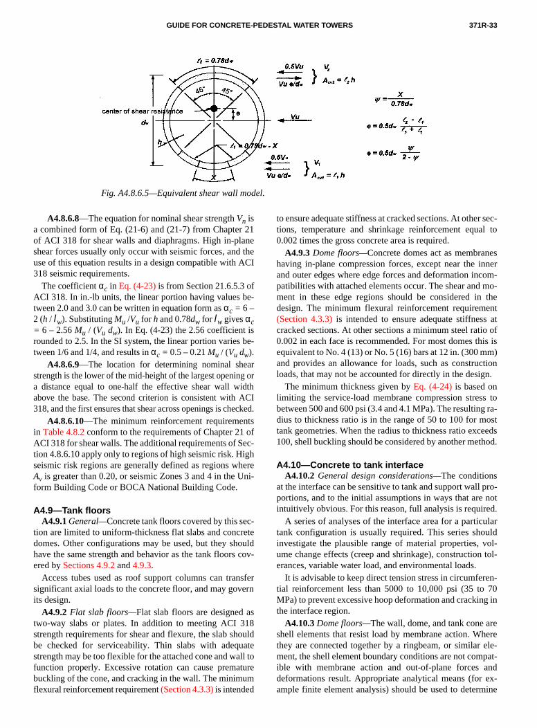
371R-33GUIDE FOR CONCRETE-PEDESTAL WATER TOWERS
Fig. A4.8.6.5—Equivalent shear wall model.
r 21ane theACI
fbe-
is be-
arg oridth ACIeckets ofec-ighhere Uni-
ec-reteould cov
nsfeern
as18oulate
all totureum
r sec-al to
nesinnercom- mo- theents atio ofhis is
m)ctiongn.
s tog ra-osteeds
thod.
l pro- noted.ularuldvol-n tol-
ren- 70
ng in
rehere ele-pat-
and ex-mine
A4.8.6.8—The equation for nominal shear strength Vn isa combined form of Eq. (21-6) and (21-7) from Chapteof ACI 318 for shear walls and diaphragms. High in-plshear forces usually only occur with seismic forces, anduse of this equation results in a design compatible with 318 seismic requirements.
The coefficient αc in Eq. (4-23) is from Section 21.6.5.3 oACI 318. In in.-lb units, the linear portion having values tween 2.0 and 3.0 can be written in equation form as αc = 6 –2 (h / lw). Substituting Mu /Vu for h and 0.78dw for lw gives αc= 6 – 2.56 Mu / (Vu dw). In Eq. (4-23) the 2.56 coefficient rounded to 2.5. In the SI system, the linear portion variestween 1/6 and 1/4, and results in αc = 0.5 – 0.21 Mu / (Vu dw).
A4.8.6.9—The location for determining nominal shestrength is the lower of the mid-height of the largest openina distance equal to one-half the effective shear wall wabove the base. The second criterion is consistent with318, and the first ensures that shear across openings is ch
A4.8.6.10—The minimum reinforcement requiremenin Table 4.8.2 conform to the requirements of Chapter 21ACI 318 for shear walls. The additional requirements of Stion 4.8.6.10 apply only to regions of high seismic risk. Hseismic risk regions are generally defined as regions wAv is greater than 0.20, or seismic Zones 3 and 4 in theform Building Code or BOCA National Building Code.
A4.9—Tank floorsA4.9.1 General—Concrete tank floors covered by this s
tion are limited to uniform-thickness flat slabs and concdomes. Other configurations may be used, but they shhave the same strength and behavior as the tank floorsered by Sections 4.9.2 and 4.9.3.
Access tubes used as roof support columns can trasignificant axial loads to the concrete floor, and may govits design.
A4.9.2 Flat slab floors—Flat slab floors are designed two-way slabs or plates. In addition to meeting ACI 3strength requirements for shear and flexure, the slab shdbe checked for serviceability. Thin slabs with adequstrength may be too flexible for the attached cone and wfunction properly. Excessive rotation can cause premabuckling of the cone, and cracking in the wall. The minimflexural reinforcement requirement (Section 4.3.3) is intended
d.
-
r
to ensure adequate stiffness at cracked sections. At othetions, temperature and shrinkage reinforcement equ0.002 times the gross concrete area is required.
A4.9.3 Dome floors—Concrete domes act as membrahaving in-plane compression forces, except near the and outer edges where edge forces and deformation inpatibilities with attached elements occur. The shear andment in these edge regions should be considered indesign. The minimum flexural reinforcement requirem(Section 4.3.3) is intended to ensure adequate stiffnescracked sections. At other sections a minimum steel rat0.002 in each face is recommended. For most domes tequivalent to No. 4 (13) or No. 5 (16) bars at 12 in. (300 mand provides an allowance for loads, such as construloads, that may not be accounted for directly in the desi
The minimum thickness given by Eq. (4-24) is based onlimiting the service-load membrane compression stresbetween 500 and 600 psi (3.4 and 4.1 MPa). The resultindius to thickness ratio is in the range of 50 to 100 for mtank geometries. When the radius to thickness ratio exc100, shell buckling should be considered by another me
A4.10—Concrete to tank interfaceA4.10.2 General design considerations—The conditions
at the interface can be sensitive to tank and support walportions, and to the initial assumptions in ways that areintuitively obvious. For this reason, full analysis is requir
A series of analyses of the interface area for a partictank configuration is usually required. This series shoinvestigate the plausible range of material properties, ume change effects (creep and shrinkage), constructioerances, variable water load, and environmental loads.
It is advisable to keep direct tension stress in circumfetial reinforcement less than 5000 to 10,000 psi (35 toMPa) to prevent excessive hoop deformation and crackithe interface region.
A4.10.3 Dome floors—The wall, dome, and tank cone ashell elements that resist load by membrane action. Wthey are connected together by a ringbeam, or similarment, the shell element boundary conditions are not comible with membrane action and out-of-plane forces deformations result. Appropriate analytical means (forample finite element analysis) should be used to deter

371R-34 MANUAL OF CONCRETE PRACTICE
ng- thteestin forac
deendinnt
er-
tonc-
-lties conying
ithwaete baciak t
Coners
and wied mm onperructhe
tegim
ring psite-
to tha annly
r in theec-
ro- orre
es onist-, but an-
toely
nd-ent
ctr tor-de-
or an-s ofagm
seser-000ser- ex-ut
mpro-hni-t inonshis
ion.rm
f theideg:
of
ich
soil
en
al-
able
the stress in connecting elements in the vicinity of the ribeam. Where the analysis shows a net tensile strain inringbeam, the lower portion of the steel cone and its sconnecting elements may be included as elements resitension forces. The wall and dome should be designedshear, direct tension and flexural tension caused by intetion effects in the vicinity of the ringbeam.
A4.10.4 Slab floors—Shrinkage will affect the forces anstresses arising from the incompatibility of strains betwthe tank cone and the slab. Shrinkage will also cause benmoments in the top of the wall, for which reinforcemeshould be provided in the wall both vertically and circumfentially some distance below the top of the wall.
A4.10.5—Suspended steel floorsA4.10.5.1—This design has no concrete dome or slab
maintain circularity and is sensitive to construction toleraes that can cause additional load due to misalignment.
A4.10.5.3 and A4.10.5.4—The requirements for concrete elements supporting base plates reflect the difficuassociated with centering annular base plates on narrowcrete supports, the effect of eccentric loads on load-carrcapacity, and the potential for edge spalling. Experience wgrouted base plates supported directly on the support has shown that regular checking and adjustment of diamand curvature are necessary to position the center of theplate and skirt at the center of the wall. Where no spemeasures are implemented to ensure fit of the steel tanthe concrete construction, a ringbeam is recommended. structors that build without a ringbeam generally use lasto control alignment and shape during wall construction, check the as-built condition to ensure that the base platefit on the wall within the specified tolerances. A combininside and outside edge distance not less than 6 in. (150is required to ensure that the base plate will fit properlythe wall. A smaller edge distance may be used when exence with the form system, steel fabrication, and consttion tolerance controls result in fit of the base plate to wall construction within the tolerances specified.
A4.10.5.5—The minimum recommended base plawidth of 6 in. (150 mm) is the minimum required for usinanchor bolts, and provides for grout side cover of shstacks that are generally not removed. The grout beastrength for factored loads is conservatively limited to 2000(14 MPa) because of the difficulty of inspection and mainnance of this detail.
A4.10.5.6—The grout that transfers the steel tank loadthe concrete support structure is a key structural elementis not readily accessible for inspection and maintenance,is often neglected in specifications and construction. Ohigh-quality, durable materials should be used, and theistallation should be carefully supervised to ensure thatwork complies with specifications and manufacturer’s rommendations.
A4.10.6 Reinforcement details—Minimum radial and cir-cumferential reinforcement of 0.25 percent should be pvided for temperature and shrinkage during constructionwhen the tank is empty, even at sections that are in compsion during their service life.
elgr-
g
-
llrselo-
ll
)
i--
td
-
s-
A4.11—Foundation designA4.11.3 Overturning—The location of the centroid of th
resisting load used to calculate the stability ratio dependthe rigidity of the foundation used. The centroid of the resing load may be taken near the edge of raft foundationsmay be near or inside the support structure wall when annular ring foundation is used.
A4.11.4.1—The ratio of foundation outside diameter mean support wall diameter will not exceed approximat1.45 for an annular ring foundation [Fig. 4.11.1(a)] designedas a one-way strip where torsional effects and biaxial being are not considered. Where bearing capacity or settlemlimits require a foundation with a significantly larger contaarea, a raft or a deep foundation should be considered, osional effects and biaxial bending must be included in signing the annular ring foundation.
A4.11.5.3—When lateral loads are resisted by pilespiers, significant in-plane shear and moment may exist innular ring pile or pier caps. For narrow annular ring caplarge diameter, it may be necessary to provide a diaphrto distribute the load to the piles or drilled piers.
A4.11.6.3—A check at service loads is required becaua load factor of less than 1.7 for water may result in high vice load stress in the foundation reinforcement. The 30,psi (205 MPa) limit on tension reinforcement stress at vice loads provides a reasonable upper limit to preventcessive deflection and cracking of concrete withoextensive computational effort. Alternatively, Eq. (4-2) canbe used for crack control.
A4.12—Geotechnical recommendationsA4.12.1.2—Structure configuration, loads, and minimu
requirements for the geotechnical investigation should be vided to the design professional responsible for the geoteccal investigation. Local experience is a valuable asseevaluating potential geotechnical and geological conditithat may affect the foundation design and construction. Texperience may also provide for a more efficient investigat
Field investigation and laboratory testing should confoto ASTM specifications and recognized procedures.
The geotechnical report should document the results ofield investigation, laboratory testing, analysis, and provrecommendations. The report should contain the followin
(a) Geology of the site, boring logs and classificationsoils;
(b) Summary of field and laboratory testing;(c) Ground water encountered, and the depth at wh
buoyancy should be considered;(d) Seismic soil type classification, and assessment of
liquefaction potential;(e) Foundation soil stiffness for dynamic analysis, wh
required;(f) Bearing capacity and depth of bearing stratum for sh
low foundation;(g) Types of deep foundations that may be used; prob
bearing stratum; and expected capacity;(h) Lateral load capacity of deep foundations;(i) Tension uplift capacity of deep foundations;(j) Unit weight of compacted backfill soils;

371R-35GUIDE FOR CONCRETE-PEDESTAL WATER TOWERS
bleoi
b
dn-le- ofctsenvid
ntin fo ec
le fain-in
re
ce
ofec.5
ate
atener. cafe
aticna
er
inew-
afetydr
atu-dur-theter-pre-ified
in-00atedize
umd tot ex-ro-ter
er.t at
at-t be-dderthe
rthel ac-) oruip-en-est
rederedeans
(k) Construction requirements, including: expected staexcavation slopes, dewatering requirements, use of site sfor backfill, and compaction requirements.
A4.12.2 Foundation depth—Maps of frost penetrationdepth are available from the U.S. Weather Bureau, or canfound in model building codes or their commentary.
A4.12.3 Settlement limits—Concrete-pedestal tanks antheir foundations are relatively rigid structures that can udergo significant total settlement without distress. Settment of deep foundations is usually smaller than thatshallow foundations, and the smaller settlement limit reflethe expected behavior. The effects of foundation movemrelative to slabs and piping should be considered and proed for by properly designed connection details.
Tilting of the structure caused by differential settlemeacross the foundation width causes secondary overturnmoments, and the structural effects of this are accountedin the design of the superstructure and foundation by thecentricity load term G. A minimum assumed tilt of 1/800 isincluded in the design through Eq. (4-1a). Larger differentialtilt is permitted when included in Eq. (4-1b).
A4.12.4 Shallow foundations—A global factor of safety of3.0 is used for sizing shallow foundations using allowabstress design. Where settlement controls the design, thetor of safety is even larger. Analytical methods for determing the maximum bearing pressure can be found references on foundation design.
Ultimate strength design may also be used to determinequired bearing area using the following equation
qu = φs qr
The factored soil bearing pressure qu is calculated fromloads in Section 4.2.3. The shallow foundation performanfactor φs is 0.5.
The shallow foundation performance factor φs used withultimate strength design provides a global factor of safety3.0 when used with the factored load combinations of Stion 4.2.3 whose average load factor is approximately 1The ultimate bearing capacity qr is the smaller of: 3.0 timesthe allowable bearing capacity for settlement, or the ultimbearing capacity of the soil determined in Section 4.12.4.1.
A4.12.5 Deep foundations—A variable global factor ofsafety that depends on the method of determining the ultimcapacity is used with deep foundations. Where settlemcontrols the design, the factor of safety will be even largDeep foundation elements, such as drilled piers, whosepacity is based on calculations use a minimum factor of saty of 3.0, the same as for shallow foundations. Where stload testing is used the safety factor is reduced to 2.0. Alytical methods for determining the maximum pile or piload can be found in references on foundation design.
Ultimate strength design may also be used to determthe required number of drilled piers or piles using the folloing equation
Qu = φp Qr
ls
e
t-
gr-
c-
-
-.
et
--
-
The factored pile or pier load Qu is calculated from loads inSection 4.2.3. The deep foundation performance factor φp isfrom Table A4.12.5.
Table A4.12.5—Performance factor for deep foundations
The deep foundation performance factor φp used with ulti-mate strength design provides the same global factor of sas listed in Table 4.12.5 when used with the factored loacombinations of Section 4.2.3 where the average load factois approximately 1.5.
A4.12.6 Seismic requirements—Relatively fine-grainedsoils in a relatively loose state of compaction, and in a srated or submerged condition are subject to liquefaction ing earthquake excitation. Where these soils occur, suitability of a site for a concrete-pedestal elevated wastorage tank should be carefully evaluated. Any special cautions that are required in the design should be identprior to design.
CHAPTER 5—APPURTENANCES AND ACCESSORIES COMMENTARYA5.4—Tank Access
A5.4.2 Ladders—The following details are commonlyused for ladders.
(a) Side rails are a minimum 3/8 in. (10 mm) by 2 in. (50mm) with a 16 in. (410 mm) clear spacing. Rungs are a mimum 3/4 in. (20 mm) round or square, spaced at 12 in. (3mm) centers. The surface should be knurled, dimpled, cowith skid-resistant material, or otherwise treated to minimslipping.
(b) At platforms or landings the ladder extends a minimof 48 in. (1.2 m) above the platform. Ladders are securethe adjacent structure by brackets located at intervals noceeding 10 ft (3 m). Brackets have sufficient length to pvide a minimum distance of 7 in. (180 mm) from the cenof rung to the nearest permanent object behind the ladd
Where cages are provided, ladders should be offselanding platforms. The maximum interval between plforms should not exceed 30 ft (9 m). Cages should startween 7 and 8 ft (2.1 and 2.4 m) above the base of the laand should extend a minimum of 48 in. (1.2 m) above offset landing platform.
A5.4.5 and A5.4.6 Steel tank roof openings and floomanhole—Commonly used opening sizes for access to tank interior are given. Openings used only for personnecess should have a least dimension of 24 in. (610 mmlarger. Larger openings may be required for painter's eqment or other interior maintenance items. At least one oping should be of sufficient size to accommodate the larganticipated equipment. A tank floor manhole is not requifor operation and maintenance of the tank, but is considan appurtenance for safety reasons in that it provides a mof egress other than the roof manholes. Furthermore, it is a
Ultimate Capacity in Accordance with Section
Ultimate Strength Performance Factor
4.12.5.1(a) 0.54.12.5.1(b) 0.754.12.5.1 (c) 0.754.12.5.1(d) 0.6

371R-36 MANUAL OF CONCRETE PRACTICE
-ser-
re ju-ll as
- ofer-
lowtor.
han tod-
ralge.nge
ious rea
edm)
Theuck
axle
ccor
ls isble
this 360 re-ce-
dg akfillfied
- flatl di-iatecretloadto th
m-
r-)
ct
n-
n-
n-d
r
ion
a-
ng
are
ewble00,
practical access opening during construction and out-ofvice maintenance.
A5.6—Above-ground pipingA5.6.2.6—Typically inlet safety protection is provided fo
pipes of 18 in. (460 mm) diameter and greater, but somrisdictions may require inlet protection for pipes as sma8 in. (200 mm) in diameter.
A5.6.3 Overflow—An overflow is a protection device intended to prevent over-filling and possible overloadingthe tank. An overflowing tank should be considered an emgency condition. The condition causing the tank to overfshould be promptly determined and rectified by the opera
A5.8—Interior floorsA5.8.2—Slabs on gradeA5.8.2.1—It is assumed that if door openings are less t
8 ft (2.4 m) wide, that the floor slab will only be subjectedfoot traffic and occasional light vehicle traffic. Truck loaing should be expected for wider doors.
The optimum concrete mix has the maximum flexustrength with the least mixing water to minimize shrinkaConcrete with a specified compressive strength in the raof 3500 to 4000 psi (24 to 28 MPa) and a water-cementitmaterial ratio less than 0.45 can be expected to providesonable performance.
The 5 in. (125 mm) minimum thickness is recommendwhen only light vehicle traffic is expected, and a 4 in. (100 mthickness may be used when only foot traffic is expected.6 in. (150 mm) minimum thickness recommended where trdoors are furnished is adequate for 15 ton (13.6 tonne)loads for most subgrade soils.
The minimum reinforcement requirements in Table 5.8.2are shrinkage and temperature steel requirements in adance with ACI 318.
A5.8.2.2—The inside diameter of most concrete pedestaless than 70 ft (21 m), and the minimum reinforcement in Ta5.8.2 is adequate for controlling cracking for slab widths to width. This is based on the subgrade drag equation in ACIusing a friction coefficient of 2.0 and an allowable stress ininforcement of 40,000 psi (276 MPa). Continuous reinforment with contraction joints is commonly used.
A5.8.2.5—Minimum compaction of 95 percent modifieProctor density is recommended for backfill supportinslab-on-grade subject to vehicle traffic. Otherwise, bacshould be compacted to a minimum of 90 percent modiProctor density.
A5.8.3 Intermediate floors—Various structural configurations are used for above grade floors. The simplest is aslab supported by the wall, which may be used for smalameter walls. For larger spans, flat slabs with intermedcolumns, and concrete or steel beams supporting a conslab are generally used. Care must be taken that the from the beam end reactions are adequately transferred supporting wall, and are accounted for in the design.
-
-
ese
Commentary recommended references—The followingdocuments with their serial designation are cited in the Comentary only. Other references are listed in Chapter 6.
American Concrete InstituteACI 201.2R Guide to Durable ConcreteACI 212.3R Chemical Admixtures for ConcreteACI 212.4R Guide for the Use of High-Range Wate
Reducing Admixtures (Superplasticizersin Concrete
ACI 224.2R Cracking of Concrete Members in DireTension
ACI 301 Standard Specification for Structural Cocrete
ACI 303R Guide to Cast-in-Place Architectural Cocrete Practice
ACI 307 Standard Practice for the Design and Costruction of Cast-in-Place ReinforceConcrete Chimneys
ACI 334.2R Reinforced Concrete Cooling ToweShells—Practice and Commentary
American Association of State Highway and TransportatOfficials
Standard Specifications for Highway Bridges
American Water Works AssociationD100 Standard for Welded Steel Tanks for W
ter Storage
The above publications may be obtained from the followiorganizations:
American Association of State Highway andTransportation Officials444 North Capitol Street NW, Suite 225Washington, D.C. 20001
American Concrete InstituteP.O. Box 9094Farmington Hills, Mich. 48333-9094
American Water Works Association6666 West Quincy AvenueDenver, Colo. 80235
Commentary cited references—The following documentis cited in the Commentary only. Other cited references listed in Chapter 6.
1. “NEHRP Recommended Provisions for Seismic Regulations for NBuildings,” Part 2—Commentary, 1994 Ed. The publication is availafrom the Building Seismic Safety Council, 1201 L Street NW, Suite 4Washington, D.C. 20005.