3810498 specifications manual l10 series engines external damper models
TRANSCRIPT
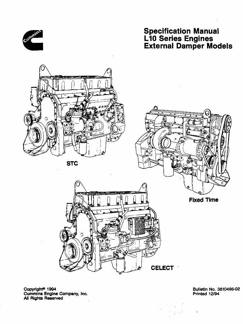

ForewordThis manual contains complete assembly and rebuild specifications for the external damper model L10 engineand all associated components manufactured by Cummins Engine Company, Inc. This manual is intended as aquick reference guide for an experienced technician who is familiar with our product. Various accessory andcomponent suppliers can be contacted directly for any information not covered in this manual.
A series of specific service manuals (Troubleshooting and Repair, Shop, Alternative Repair, and so on) areavailable and can be ordered by filling out and mailing the Literature Order Form located at the end of this manual.
Reporting of errors, omissions, and recommendations for improving this publication by the user is encouraged.Please use the postage paid, self-addressed Literature Survey Form at the end of this manual for communicatingyour comments.
The specifications in this manual are based on the most current information at the time of publication. CumminsEngine Company, Inc. reserves the right to initiate any changes at any time without obligation. If differences arefound between your engine and the information in this manual, contact a Cummins Authorized Repair Location,a Cummins Division Office, or the factory.
The latest technology and the highest quality components are used to manufacture the products of CumminsEngine Company, Inc. When replacement parts are needed, we recommend using only genuine Cummins orReConT exchange parts. These parts can be identified by the following trademarks:
Table of Contents
Page
Additional Service Literature ............................................................................................................................. 59
Capscrew Markings and Torque Values ............................................................................................................ 53Capscrew Markings and Torque Values - Metric .............................................................................................. 53Capscrew Markings and Torque Values - U.S. Customary ............................................................................... 54
Component Manufacturers’ Addresses ............................................................................................................. 56Air Compressors .............................................................................................................................................. 56Air Cylinders .................................................................................................................................................... 56Air Heaters....................................................................................................................................................... 56Air Starting Motors........................................................................................................................................... 56Alternators ....................................................................................................................................................... 56Auxiliary Brakes ............................................................................................................................................... 56Belts ................................................................................................................................................................ 56Clutches .......................................................................................................................................................... 56Coolant Heaters ............................................................................................................................................... 56Drive Plates ..................................................................................................................................................... 56Electric Starting Motors.................................................................................................................................... 56Engine Protection Controls............................................................................................................................... 57Fan Clutches ................................................................................................................................................... 57Fans ................................................................................................................................................................ 57Filters .............................................................................................................................................................. 57Flexplates ........................................................................................................................................................ 57Fuel Warmers .................................................................................................................................................. 57Gauges ............................................................................................................................................................ 57Governors ........................................................................................................................................................ 57Hydraulic and Power Steering Pumps .............................................................................................................. 57Oil Heaters....................................................................................................................................................... 58Torque Converters ........................................................................................................................................... 58
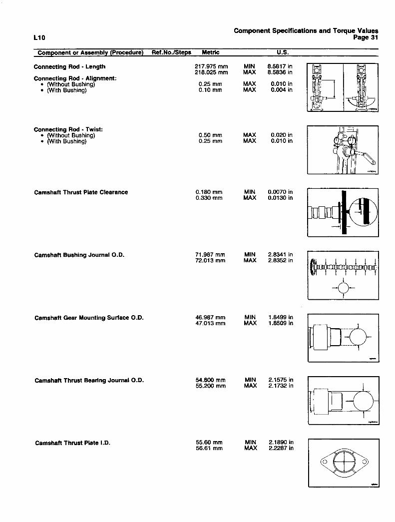
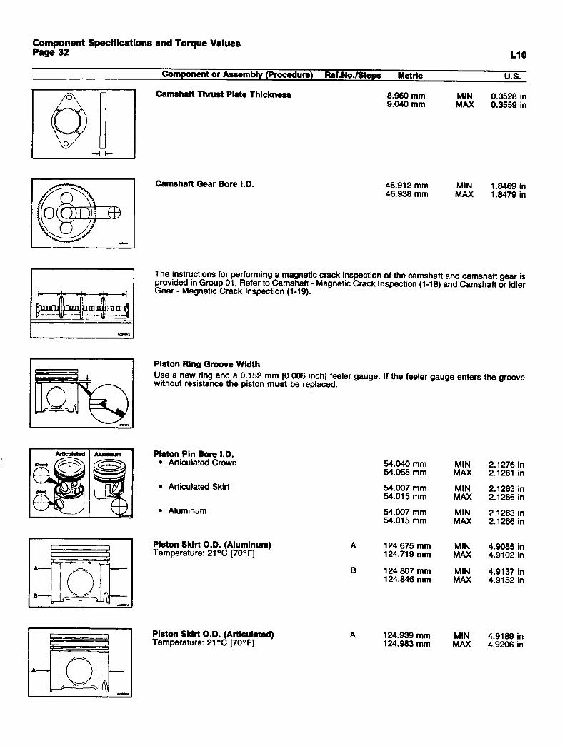
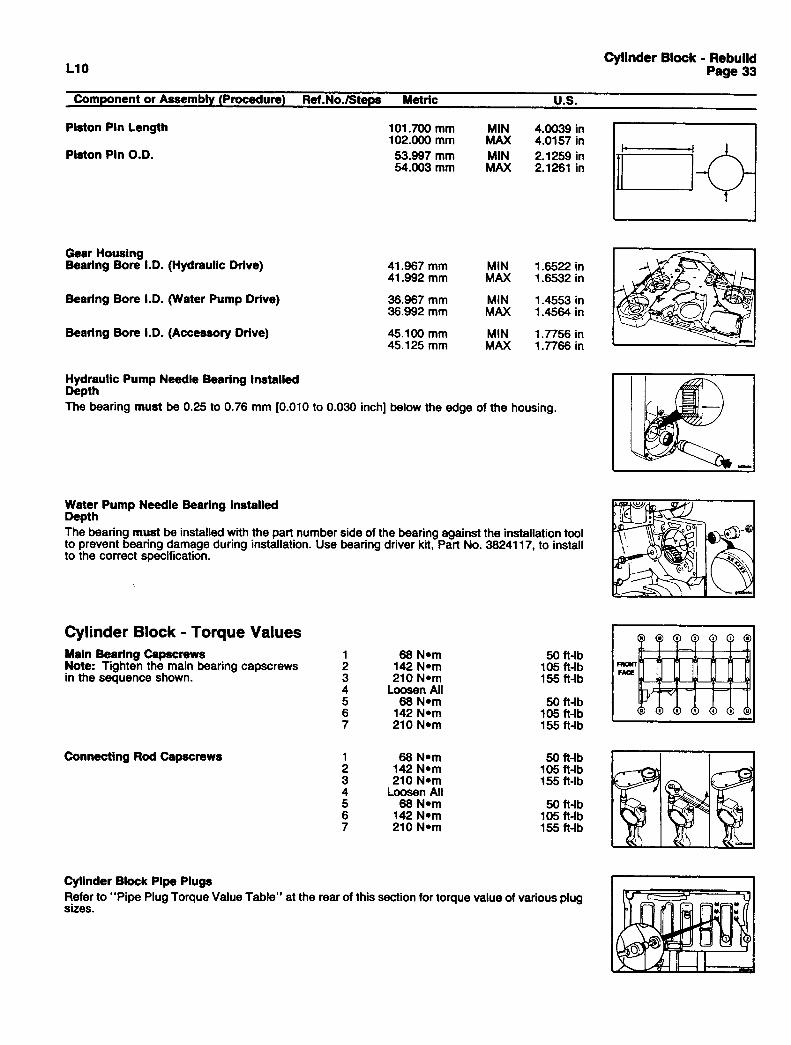
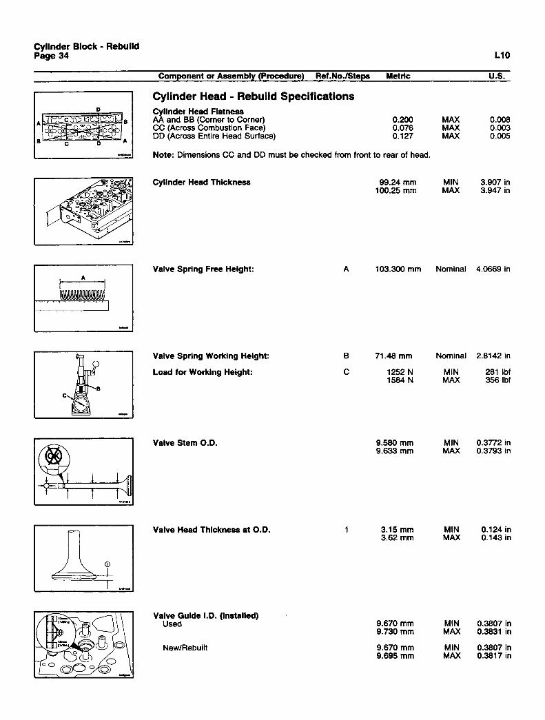
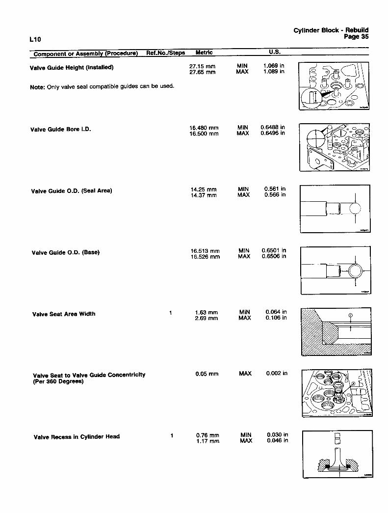
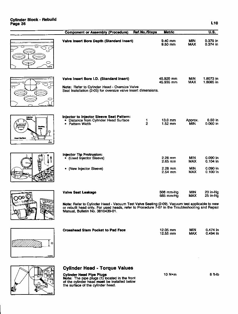
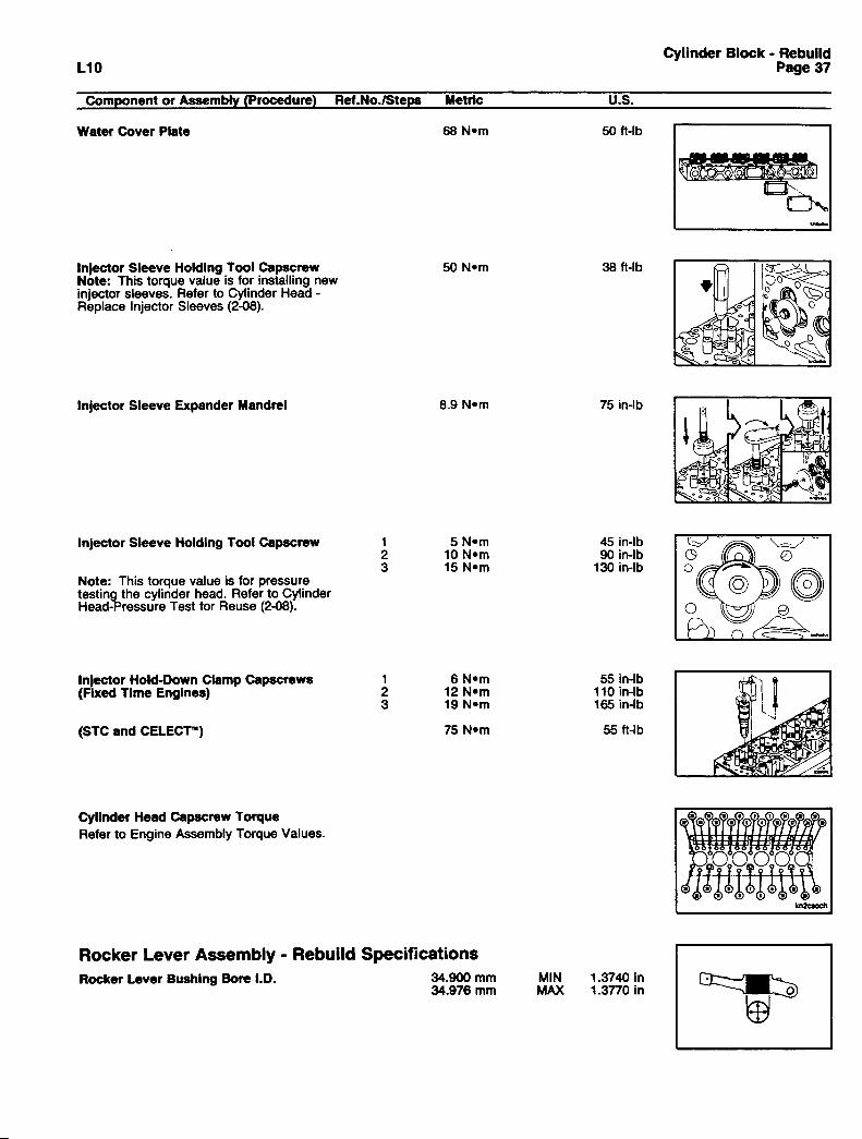
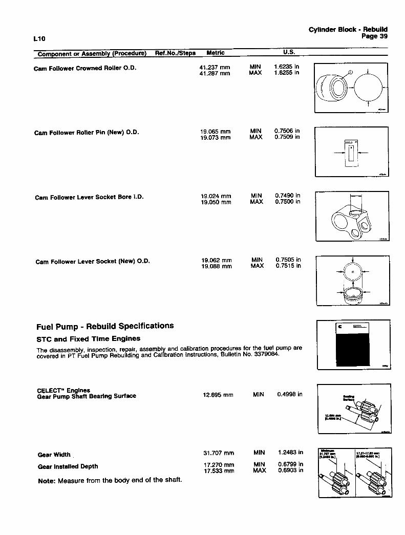
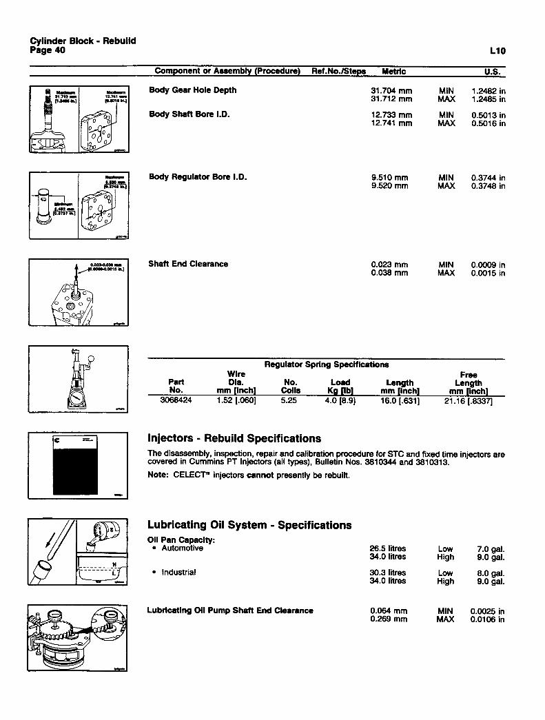
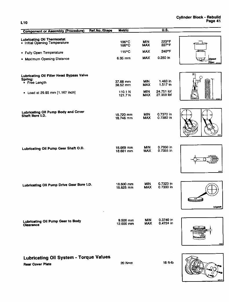
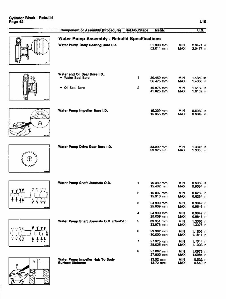
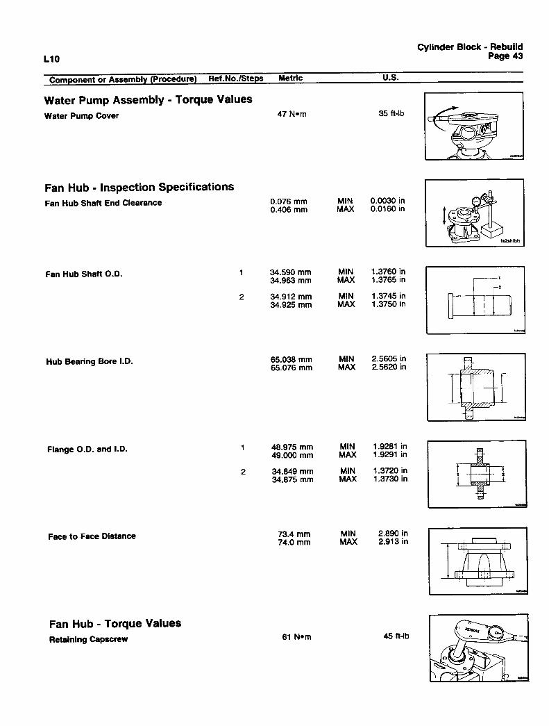
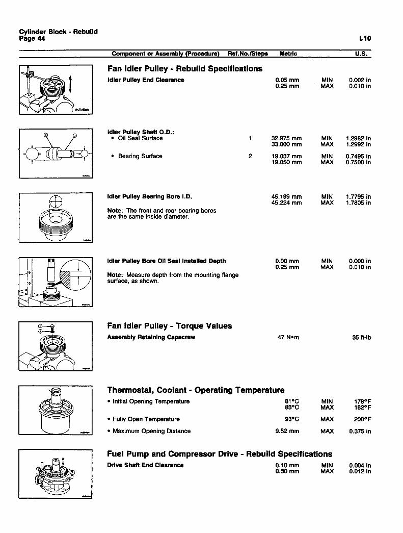
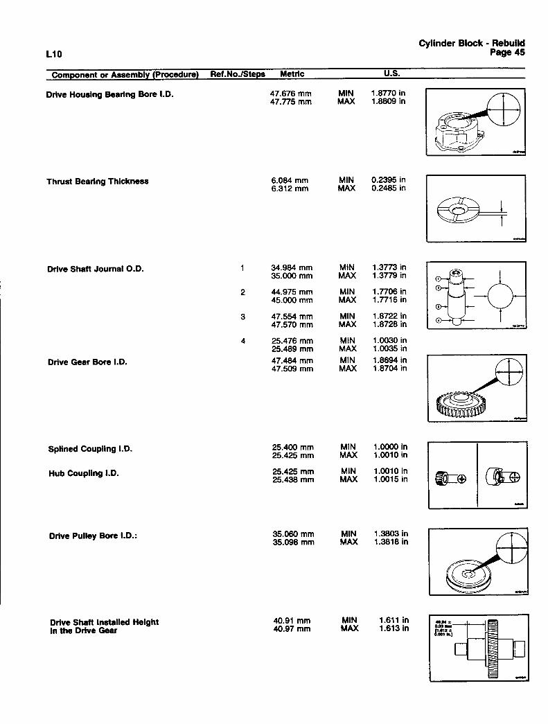
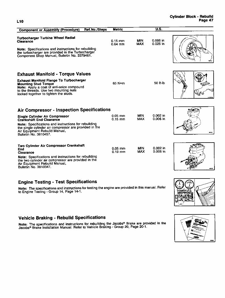
Component Specifications and Torque Values ................................................................................................. 10Air Compressor - Inspection Specifications ...................................................................................................... 47Cam Follower Assembly - Rebuild Specifications ............................................................................................ 38Cylinder Block - Rebuild Specifications ............................................................................................................ 26Cylinder Block - Torque Values........................................................................................................................ 33Cylinder Head - Rebuild Specifications ............................................................................................................ 34Cylinder Head - Torque Values ........................................................................................................................ 36Engine Assembly - Capscrew Torque Values ................................................................................................... 15Engine Assembly - Specifications..................................................................................................................... 10Engine Testing - Test Specifications ................................................................................................................ 47Exhaust Manifold - Torque Values.................................................................................................................... 47Fan Hub - Inspection Specifications ................................................................................................................. 43Fan Hub - Torque Values................................................................................................................................. 43Fan Idler Pulley - Rebuild Specifications .......................................................................................................... 44Fan Idler Pulley - Torque Values ...................................................................................................................... 44Fuel Pump - Rebuild Specifications.................................................................................................................. 39Fuel Pump and Compressor Drive - Rebuild Specifications.............................................................................. 44Hydraulic Pump Drive - Rebuild Specifications................................................................................................. 46Injectors - Rebuild Specifications ..................................................................................................................... 40Lubricating Oil System - Specifications ............................................................................................................ 40Lubricating Oil System - Torque Values ........................................................................................................... 41Rocker Lever Assembly - Rebuild Specifications.............................................................................................. 37Thermostat, Coolant - Operating Temperature ................................................................................................. 44Turbocharger - Inspection Specifications.......................................................................................................... 46Vehicle Braking - Rebuild Specifications .......................................................................................................... 47Water Pump Assembly - Rebuild Specifications ............................................................................................... 42Water Pump Assembly - Torque Values ........................................................................................................... 43
Drive Belt Tension.............................................................................................................................................. 49
Engine Diagrams .................................................................................................................................................. 3
Engine Identification ............................................................................................................................................ 1ECM Dataplate(s)............................................................................................................................................... 2Engine Dataplate ............................................................................................................................................... 1Fuel Pump Dataplate ......................................................................................................................................... 2
Page
Engine Specifications .......................................................................................................................................... 7Air Induction System.......................................................................................................................................... 7Batteries (Specific Gravity)................................................................................................................................. 8Cooling System.................................................................................................................................................. 7Electrical System ............................................................................................................................................... 8Exhaust System................................................................................................................................................. 8Lubricating Oil System....................................................................................................................................... 7
General Engine Specifications............................................................................................................................. 6General Engine Data ......................................................................................................................................... 6
Injection Timing Codes ...................................................................................................................................... 48
Literature Survey Form ...................................................................................................................................... 65
Newton-Meter to Foot-Pound Conversion Chart ............................................................................................... 52
Pipe Plug Torque Values ................................................................................................................................... 54
Service Literature Ordering Location ............................................................................................................... 60
Specifications - General Information ................................................................................................................... 5
Tap-Drill Chart - U.S. Customary & Metric......................................................................................................... 55
Valve and Injector Adjustments*......................................................................................................................... 9Injector Preload (Top Stop) ................................................................................................................................ 9JacobsW Engine Brake...................................................................................................................................... 9Valve and Injector Adjustment Sequence........................................................................................................... 9Valves................................................................................................................................................................ 9
Weight and Measures - Conversion Factors...................................................................................................... 51
Engine Identification
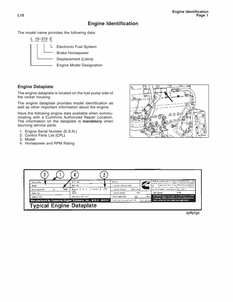
The model name provides the following data:
L 10–310 E
Electronic Fuel System
Brake Horsepower
Displacement (Liters)
Engine Model Designation
Engine Dataplate
The engine dataplate is located on the fuel pump side ofthe rocker housing.
The engine dataplate provides model identification aswell as other important information about the engine.
Have the following engine data available when commu-nicating with a Cummins Authorized Repair Location.The information on the dataplate is mandatory whensourcing service parts.
1. Engine Serial Number (E.S.N.)2. Control Parts List (CPL)3. Model4. Horsepower and RPM Rating
Engine IdentificationL10 Page 1

Fuel Pump Dataplate
On STC and Fixed Time engines, the fuel pump dataplateis located on the top of the fuel pump. It provides infor-mation for fuel pump calibration.
ECM Dataplate(s)
On CELECT™ engines, there are two dataplates on thetop of the electronic control module (ECM). The dataplateon the left contains the part number (P/N), serial number(S/N) and the data code (D/C) of the ECM. The dataplateon the right contains the engine calibration information.
Engine IdentificationL10Page 2
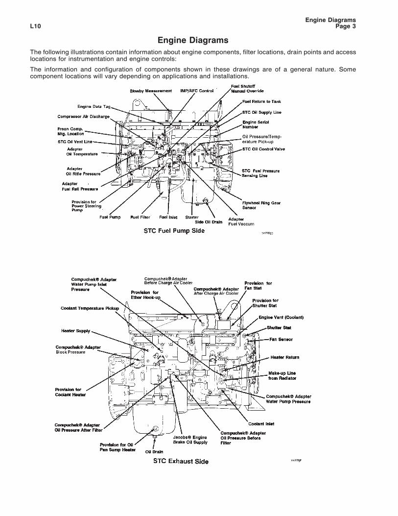
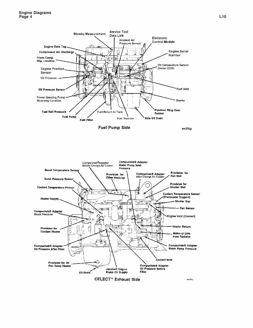
Engine Diagrams
The following illustrations contain information about engine components, filter locations, drain points and accesslocations for instrumentation and engine controls:
The information and configuration of components shown in these drawings are of a general nature. Somecomponent locations will vary depending on applications and installations.
Engine DiagramsL10 Page 3
Engine DiagramsL10Page 4
Specifications - General Information
The specifications in this manual are organized in the same sequence as the L10 Series Engine Shop Manual,External Damper Models, Bulletin No. 3810476. The minimum and maximum tolerance limit specifications arelisted in both metric and U.S. Customary dimensions. The metric dimension is given first, followed by the U.S.Customary dimension in brackets; for example: 0.50 mm [0.020 inch]. The assembly and rebuild specificationsand torque values are provided to be sure the parts are assembled correctly, fit properly, and are secured withthe correct torque value.
Most of the capscrews used to assemble the L10 engine are metric. Some components, such as the air compressorand the fuel pump, are installed using U.S. Customary capscrews. Capscrew torque values are listed in newtonmetres and foot pounds, unless otherwise specified. If a torque value is not listed, use the standard torque valuefor the capscrew. Refer to the Table of Contents, Capscrew Markings and Torque Values, in this manual.
Specifications - General InformationL10 Page 5
General Engine Specifications
Metric [U.S. Customary]
General Engine Data
Horsepower (Refer to the engine dataplate)
Engine speed @ Maximum Output:
• Industrial Rating (RPM) .....................................................................................................................2100
• Standard Rating (RPM) .....................................................................................................................1800
• Cruise Rating (RPM) ....................................................................................................................... 1600
Bore and Stroke ................................................................................ 125 mm [4.921 in] X 136 mm [5.354 in]
Displacement .................................................................................................................. 10 liters [611 C.I.D.]
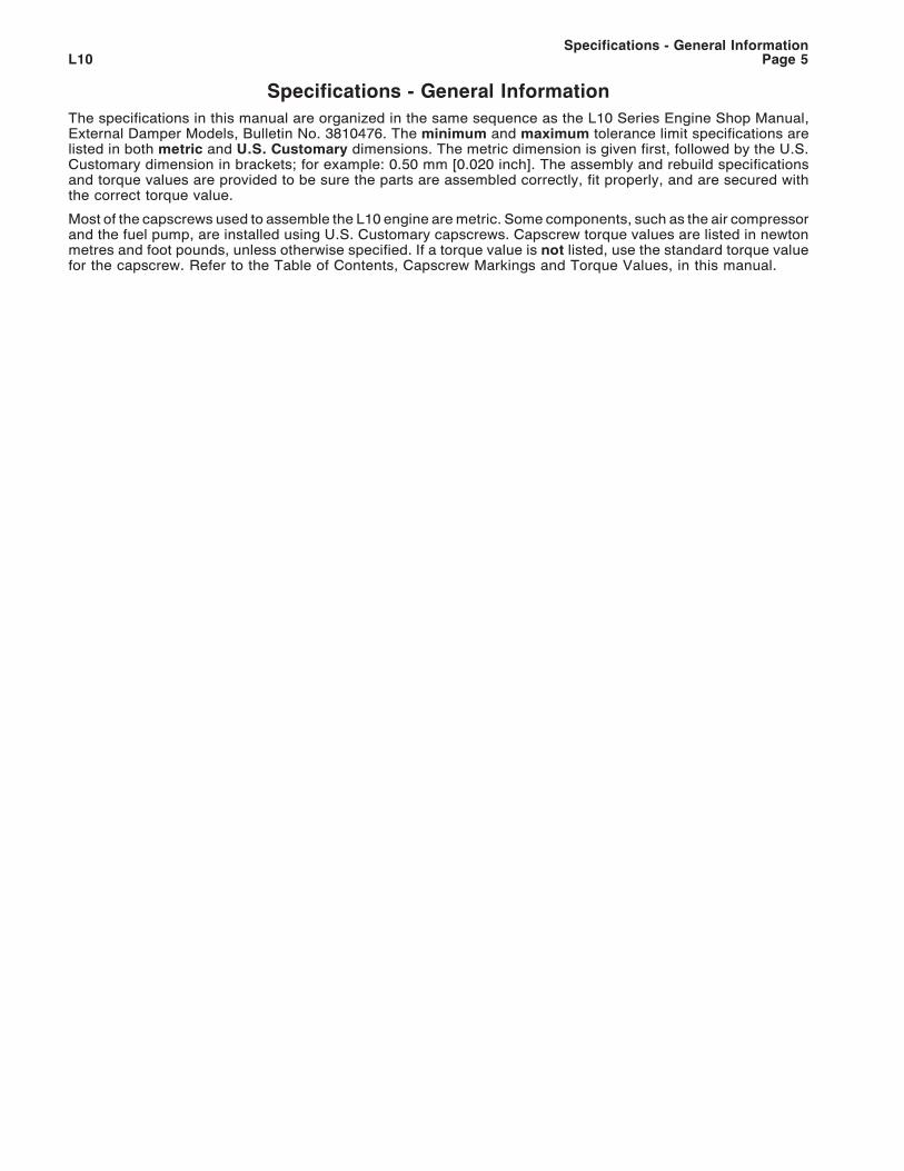
Firing Order ................................................................................................................................... 1-5-3-6-2-4
Engine Weight (with Standard Accessories):Fixed Time
• Dry Weight ............................................................................................................... 884.5 kg [1950 lb]• Wet Weight .............................................................................................................. 929.8 kg [2050 lb]
STC• Dry Weight ............................................................................................................... 891.3 kg [1965 lb]• Wet Weight .............................................................................................................. 936.6 kg [2065 lb]
CELECTY• Dry Weight ............................................................................................................... 902.6 Kg [1990 lb]• Wet Weight .............................................................................................................. 948.0 Kg [2090 lb]
Crankshaft Rotation - (viewed from the front of the engine)................................................................Clockwise
Cylinder Location and Firing Order
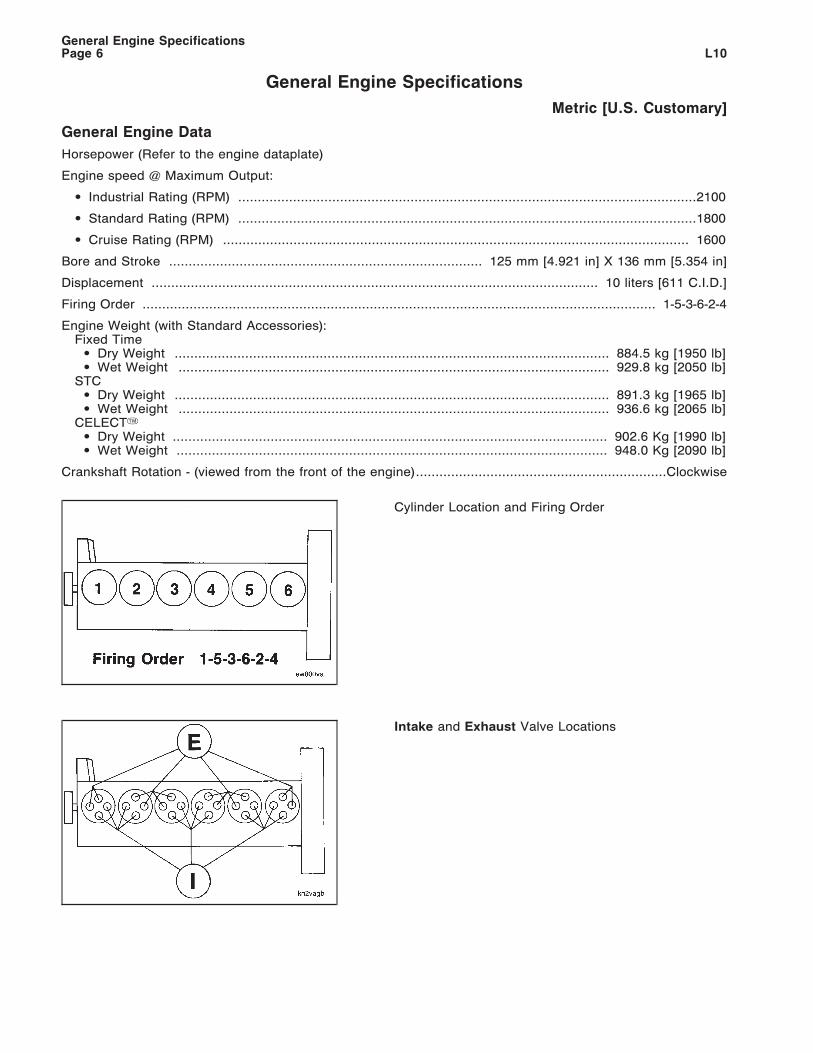
Intake and Exhaust Valve Locations
General Engine SpecificationsL10Page 6
Engine Specifications (Continued)
Metric [U.S. Customary]
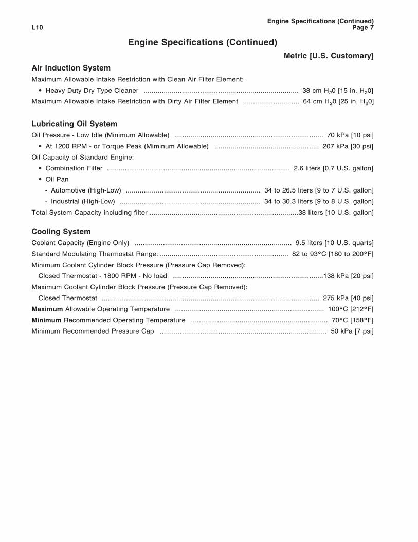
Air Induction System
Maximum Allowable Intake Restriction with Clean Air Filter Element:
• Heavy Duty Dry Type Cleaner ............................................................................. 38 cm H20 [15 in. H20]
Maximum Allowable Intake Restriction with Dirty Air Filter Element ............................ 64 cm H20 [25 in. H20]
Lubricating Oil System
Oil Pressure - Low Idle (Minimum Allowable) .......................................................................... 70 kPa [10 psi]
• At 1200 RPM - or Torque Peak (Miminum Allowable) .................................................... 207 kPa [30 psi]
Oil Capacity of Standard Engine:
• Combination Filter ........................................................................................... 2.6 liters [0.7 U.S. gallon]
• Oil Pan
- Automotive (High-Low) ................................................................... 34 to 26.5 liters [9 to 7 U.S. gallon]
- Industrial (High-Low) ...................................................................... 34 to 30.3 liters [9 to 8 U.S. gallon]
Total System Capacity including filter ..........................................................................38 liters [10 U.S. gallon]
Cooling System
Coolant Capacity (Engine Only) .............................................................................. 9.5 liters [10 U.S. quarts]
Standard Modulating Thermostat Range: ................................................................ 82 to 93°C [180 to 200°F]
Minimum Coolant Cylinder Block Pressure (Pressure Cap Removed):
Closed Thermostat - 1800 RPM - No load ...........................................................................138 kPa [20 psi]
Maximum Coolant Cylinder Block Pressure (Pressure Cap Removed):
Closed Thermostat ............................................................................................................ 275 kPa [40 psi]
Maximum Allowable Operating Temperature .......................................................................... 100°C [212°F]
Minimum Recommended Operating Temperature .................................................................... 70°C [158°F]
Minimum Recommended Pressure Cap ................................................................................... 50 kPa [7 psi]
Engine Specifications (Continued)L10 Page 7
Engine Specifications (Continued)
Metric [U.S. Customary]
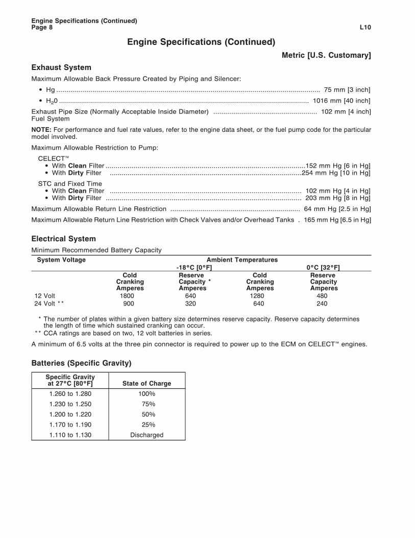
Exhaust System
Maximum Allowable Back Pressure Created by Piping and Silencer:
• Hg .................................................................................................................................... 75 mm [3 inch]
• H20 ............................................................................................................................. 1016 mm [40 inch]
Exhaust Pipe Size (Normally Acceptable Inside Diameter) .................................................... 102 mm [4 inch]Fuel System
NOTE: For performance and fuel rate values, refer to the engine data sheet, or the fuel pump code for the particularmodel involved.
Maximum Allowable Restriction to Pump:
CELECT™• With Clean Filter ....................................................................................................152 mm Hg [6 in Hg]• With Dirty Filter ................................................................................................254 mm Hg [10 in Hg]
STC and Fixed Time• With Clean Filter ................................................................................................ 102 mm Hg [4 in Hg]• With Dirty Filter .................................................................................................. 203 mm Hg [8 in Hg]
Maximum Allowable Return Line Restriction ................................................................. 64 mm Hg [2.5 in Hg]
Maximum Allowable Return Line Restriction with Check Valves and/or Overhead Tanks . 165 mm Hg [6.5 in Hg]
Electrical System
Minimum Recommended Battery Capacity
System Voltage Ambient Temperatures-18°C [0°F] 0°C [32°F]
ColdCrankingAmperes
ReserveCapacity *Amperes
ColdCrankingAmperes
ReserveCapacityAmperes
12 Volt 1800 640 1280 48024 Volt ** 900 320 640 240
* The number of plates within a given battery size determines reserve capacity. Reserve capacity determinesthe length of time which sustained cranking can occur.
** CCA ratings are based on two, 12 volt batteries in series.
A minimum of 6.5 volts at the three pin connector is required to power up to the ECM on CELECT™ engines.
Batteries (Specific Gravity)
Specific Gravityat 27°C [80°F] State of Charge
1.260 to 1.280 100%
1.230 to 1.250 75%
1.200 to 1.220 50%
1.170 to 1.190 25%
1.110 to 1.130 Discharged
Engine Specifications (Continued)L10Page 8
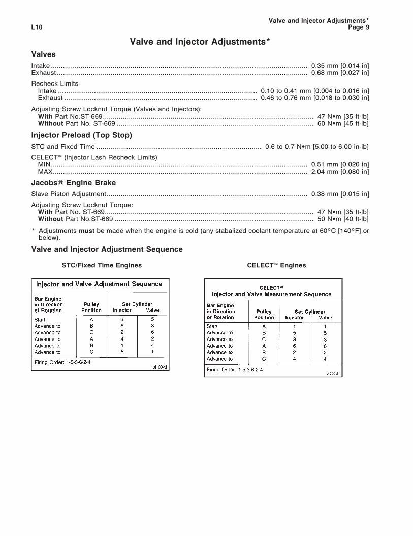
Valve and Injector Adjustments*
Valves
Intake ................................................................................................................................. 0.35 mm [0.014 in]Exhaust .............................................................................................................................. 0.68 mm [0.027 in]
Recheck LimitsIntake .................................................................................................... 0.10 to 0.41 mm [0.004 to 0.016 in]Exhaust ................................................................................................. 0.46 to 0.76 mm [0.018 to 0.030 in]
Adjusting Screw Locknut Torque (Valves and Injectors):With Part No.ST-669.......................................................................................................... 47 N•m [35 ft-lb]Without Part No. ST-669 ................................................................................................... 60 N•m [45 ft-lb]
Injector Preload (Top Stop)
STC and Fixed Time ................................................................................... 0.6 to 0.7 N•m [5.00 to 6.00 in-lb]
CELECT™ (Injector Lash Recheck Limits)MIN................................................................................................................................. 0.51 mm [0.020 in]MAX................................................................................................................................ 2.04 mm [0.080 in]
JacobsW Engine Brake
Slave Piston Adjustment..................................................................................................... 0.38 mm [0.015 in]
Adjusting Screw Locknut Torque:With Part No. ST-669......................................................................................................... 47 N•m [35 ft-lb]Without Part No.ST-669 .................................................................................................... 50 N•m [40 ft-lb]
* Adjustments must be made when the engine is cold (any stabalized coolant temperature at 60°C [140°F] orbelow).
Valve and Injector Adjustment Sequence
STC/Fixed Time Engines CELECT™ Engines
Valve and Injector Adjustments*L10 Page 9


Injection Timing Codes
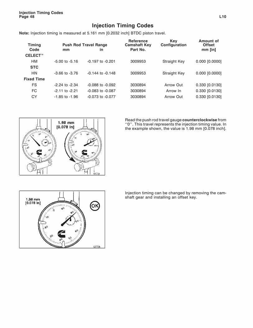
Note: Injection timing is measured at 5.161 mm [0.2032 inch] BTDC piston travel.
Timing Push Rod Travel RangeReference
Camshaft KeyKey
ConfigurationAmount of
OffsetCode mm in Part No. mm [in]
CELECT™
HM -5.00 to -5.16 -0.197 to -0.201 3009953 Straight Key 0.000 [0.0000]
STC
HN -3.66 to -3.76 -0.144 to -0.148 3009953 Straight Key 0.000 [0.0000]
Fixed Time
FS -2.24 to -2.34 -0.088 to -0.092 3030894 Arrow Out 0.330 [0.0130]
FC -2.11 to -2.21 -0.083 to -0.087 3030894 Arrow In 0.330 [0.0130]
CY -1.85 to -1.96 -0.073 to -0.077 3030894 Arrow Out 0.330 [0.0130]
Read the push rod travel gauge counterclockwise from‘‘0’’. This travel represents the injection timing value. Inthe example shown, the value is 1.98 mm [0.078 inch].
Injection timing can be changed by removing the cam-shaft gear and installing an offset key.
Injection Timing CodesPage 48 L10
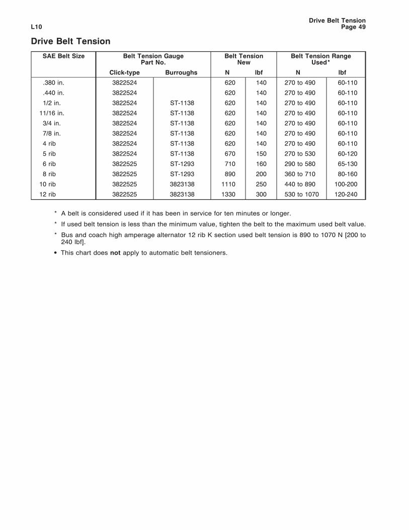
Drive Belt Tension
SAE Belt Size Belt Tension GaugePart No.
Belt TensionNew
Belt Tension RangeUsed*
Click-type Burroughs N lbf N lbf
.380 in. 3822524 620 140 270 to 490 60-110
.440 in. 3822524 620 140 270 to 490 60-110
1/2 in. 3822524 ST-1138 620 140 270 to 490 60-110
11/16 in. 3822524 ST-1138 620 140 270 to 490 60-110
3/4 in. 3822524 ST-1138 620 140 270 to 490 60-110
7/8 in. 3822524 ST-1138 620 140 270 to 490 60-110
4 rib 3822524 ST-1138 620 140 270 to 490 60-110
5 rib 3822524 ST-1138 670 150 270 to 530 60-120
6 rib 3822525 ST-1293 710 160 290 to 580 65-130
8 rib 3822525 ST-1293 890 200 360 to 710 80-160
10 rib 3822525 3823138 1110 250 440 to 890 100-200
12 rib 3822525 3823138 1330 300 530 to 1070 120-240
* A belt is considered used if it has been in service for ten minutes or longer.
* If used belt tension is less than the minimum value, tighten the belt to the maximum used belt value.
* Bus and coach high amperage alternator 12 rib K section used belt tension is 890 to 1070 N [200 to240 lbf].
• This chart does not apply to automatic belt tensioners.
Drive Belt TensionL10 Page 49

FRACTION, DECIMAL, MILLIMETER CONVERSIONS
8THS.
16THS.
32NDS.
64THS. INCHES MM
8THS.
16THS.
32NDS.
64THS. INCHES MM
1 0.0156 0.397 33 0.5156 13.097
1 0.0313 0.794 17 0.5313 13.494
3 0.0469 1.191 35 0.5469 13.891
1 0.0625 1.588 9 0.5625 14.288
5 0.0781 1.984 37 0.5781 14.684
3 0.0938 2.381 19 0.5938 15.081
7 0.1094 2.778 39 0.6094 15.478
1 0.1250 3.175 5 0.6250 15.875
9 0.1406 3.572 41 0.6406 16.272
5 0.1563 3.969 21 0.6563 16.669
11 0.1719 4.366 43 0.6719 17.066
3 0.1875 4.763 11 0.6875 17.463
13 0.2031 5.159 45 0.7031 17.859
7 0.2188 5.556 23 0.7188 18.256
15 0.2344 5.953 47 0.7344 18.653
1/4 0.2500 6.350 3/4 0.7500 19.050
17 0.2656 6.747 49 0.7656 19.447
9 0.2813 7.144 25 0.7813 19.844
19 0.2969 7.541 51 0.7969 20.241
5 0.3125 7.938 13 0.8125 20.638
21 0.3281 8.334 53 0.8281 21.034
11 0.3438 8.731 27 0.8438 21.431
23 0.3594 9.128 55 0.8594 21.828
3 0.3750 9.525 7 0.8750 22.225
25 0.3906 9.922 57 0.8906 22.622
13 0.4063 10.319 29 0.9063 23.019
27 0.4219 10.716 59 0.9219 23.416
7 0.4375 11.113 15 0.9375 23.813
29 0.4531 11.509 61 0.9531 24.209
15 0.4688 11.906 31 0.9688 24.606
31 0.4844 12.303 63 0.9844 25.003
1/2 0.5000 12.700 1 IN. 1.0000 25.400
CONVERSION FACTOR: 1 INCH = 25.4MM
FRACTION, DECIMAL, MILLIMETER CONVERSIONSPage 50 L10
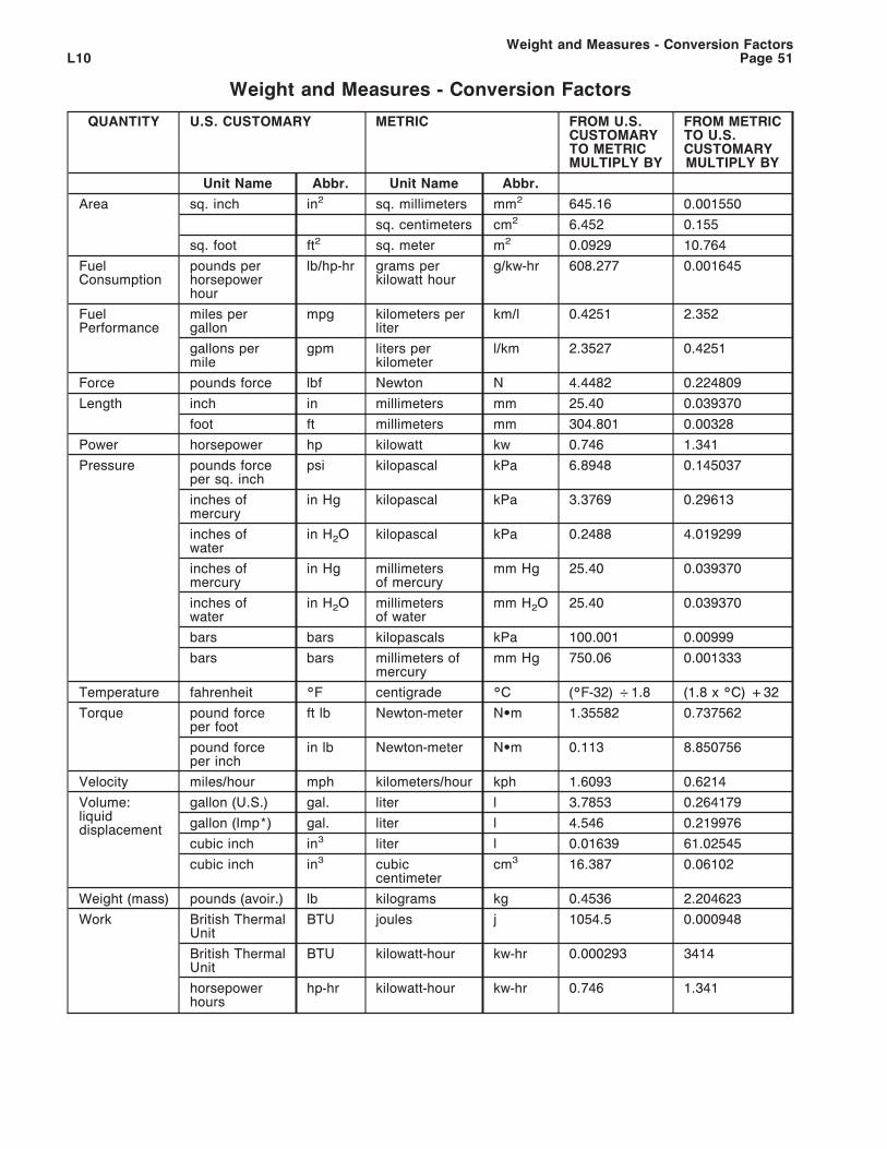
Weight and Measures - Conversion Factors
QUANTITY U.S. CUSTOMARY METRIC FROM U.S.CUSTOMARYTO METRICMULTIPLY BY
FROM METRICTO U.S.CUSTOMARYMULTIPLY BY
Unit Name Abbr. Unit Name Abbr.
Area sq. inch in2 sq. millimeters mm2 645.16 0.001550
sq. centimeters cm2 6.452 0.155
sq. foot ft2 sq. meter m2 0.0929 10.764
FuelConsumption
pounds perhorsepowerhour
lb/hp-hr grams perkilowatt hour
g/kw-hr 608.277 0.001645
FuelPerformance
miles pergallon
mpg kilometers perliter
km/l 0.4251 2.352
gallons permile
gpm liters perkilometer
l/km 2.3527 0.4251
Force pounds force lbf Newton N 4.4482 0.224809
Length inch in millimeters mm 25.40 0.039370
foot ft millimeters mm 304.801 0.00328
Power horsepower hp kilowatt kw 0.746 1.341
Pressure pounds forceper sq. inch
psi kilopascal kPa 6.8948 0.145037
inches ofmercury
in Hg kilopascal kPa 3.3769 0.29613
inches ofwater
in H2O kilopascal kPa 0.2488 4.019299
inches ofmercury
in Hg millimetersof mercury
mm Hg 25.40 0.039370
inches ofwater
in H2O millimetersof water
mm H2O 25.40 0.039370
bars bars kilopascals kPa 100.001 0.00999
bars bars millimeters ofmercury
mm Hg 750.06 0.001333
Temperature fahrenheit °F centigrade °C (°F-32) ÷1.8 (1.8 x °C) +32
Torque pound forceper foot
ft lb Newton-meter N•m 1.35582 0.737562
pound forceper inch
in lb Newton-meter N•m 0.113 8.850756
Velocity miles/hour mph kilometers/hour kph 1.6093 0.6214
Volume:liquiddisplacement
gallon (U.S.) gal. liter l 3.7853 0.264179
gallon (Imp*) gal. liter l 4.546 0.219976
cubic inch in3 liter l 0.01639 61.02545
cubic inch in3 cubiccentimeter
cm3 16.387 0.06102
Weight (mass) pounds (avoir.) lb kilograms kg 0.4536 2.204623
Work British ThermalUnit
BTU joules j 1054.5 0.000948
British ThermalUnit
BTU kilowatt-hour kw-hr 0.000293 3414
horsepowerhours
hp-hr kilowatt-hour kw-hr 0.746 1.341
Weight and Measures - Conversion FactorsL10 Page 51
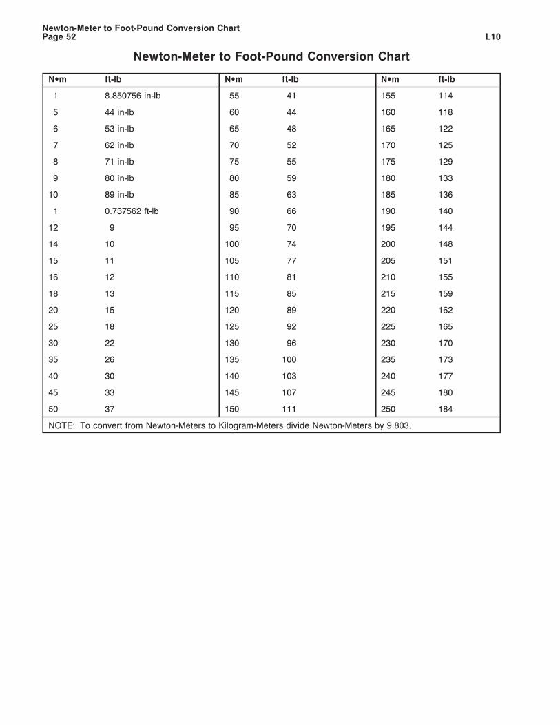
Newton-Meter to Foot-Pound Conversion Chart
N•m ft-lb N•m ft-lb N•m ft-lb
1 8.850756 in-lb 55 41 155 114
5 44 in-lb 60 44 160 118
6 53 in-lb 65 48 165 122
7 62 in-lb 70 52 170 125
8 71 in-lb 75 55 175 129
9 80 in-lb 80 59 180 133
10 89 in-lb 85 63 185 136
1 0.737562 ft-lb 90 66 190 140
12 9 95 70 195 144
14 10 100 74 200 148
15 11 105 77 205 151
16 12 110 81 210 155
18 13 115 85 215 159
20 15 120 89 220 162
25 18 125 92 225 165
30 22 130 96 230 170
35 26 135 100 235 173
40 30 140 103 240 177
45 33 145 107 245 180
50 37 150 111 250 184
NOTE: To convert from Newton-Meters to Kilogram-Meters divide Newton-Meters by 9.803.
Newton-Meter to Foot-Pound Conversion ChartPage 52 L10
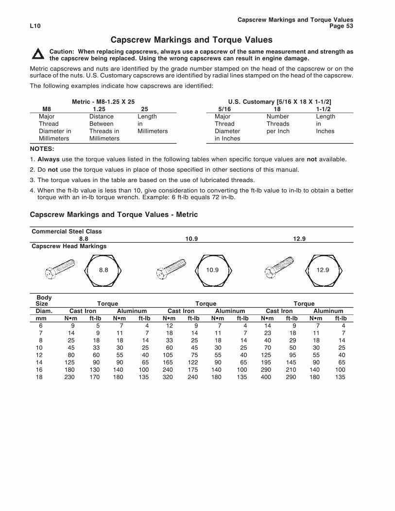
Capscrew Markings and Torque Values
Caution: When replacing capscrews, always use a capscrew of the same measurement and strength asthe capscrew being replaced. Using the wrong capscrews can result in engine damage.
Metric capscrews and nuts are identified by the grade number stamped on the head of the capscrew or on thesurface of the nuts. U.S. Customary capscrews are identified by radial lines stamped on the head of the capscrew.
The following examples indicate how capscrews are identified:
Metric - M8-1.25 X 25M8 1.25 25
Major Distance LengthThread Between inDiameter in Threads in MillimetersMillimeters Millimeters
U.S. Customary [5/16 X 18 X 1-1/2]5/16 18 1-1/2
Major Number LengthThread Threads inDiameter per Inch Inchesin Inches
NOTES:
1. Always use the torque values listed in the following tables when specific torque values are not available.
2. Do not use the torque values in place of those specified in other sections of this manual.
3. The torque values in the table are based on the use of lubricated threads.
4. When the ft-lb value is less than 10, give consideration to converting the ft-lb value to in-lb to obtain a bettertorque with an in-lb torque wrench. Example: 6 ft-lb equals 72 in-lb.
Capscrew Markings and Torque Values - Metric
Commercial Steel Class8.8 10.9 12.9
Capscrew Head Markings
8.8 10.9 12.9
BodySize Torque Torque TorqueDiam. Cast Iron Aluminum Cast Iron Aluminum Cast Iron Aluminummm N•m ft-lb N•m ft-lb N•m ft-lb N•m ft-lb N•m ft-lb N•m ft-lb6 9 5 7 4 12 9 7 4 14 9 7 47 14 9 11 7 18 14 11 7 23 18 11 78 25 18 18 14 33 25 18 14 40 29 18 14
10 45 33 30 25 60 45 30 25 70 50 30 2512 80 60 55 40 105 75 55 40 125 95 55 4014 125 90 90 65 165 122 90 65 195 145 90 6516 180 130 140 100 240 175 140 100 290 210 140 10018 230 170 180 135 320 240 180 135 400 290 180 135
Capscrew Markings and Torque ValuesL10 Page 53
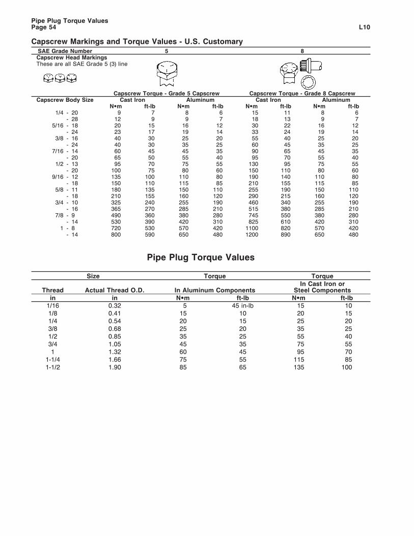
Capscrew Markings and Torque Values - U.S. CustomarySAE Grade Number 5 8Capscrew Head MarkingsThese are all SAE Grade 5 (3) line
Capscrew Torque - Grade 5 Capscrew Capscrew Torque - Grade 8 CapscrewCapscrew Body Size Cast Iron Aluminum Cast Iron Aluminum
N•m ft-lb N•m ft-lb N•m ft-lb N•m ft-lb1/4 - 20 9 7 8 6 15 11 8 6
- 28 12 9 9 7 18 13 9 75/16 - 18 20 15 16 12 30 22 16 12
- 24 23 17 19 14 33 24 19 143/8 - 16 40 30 25 20 55 40 25 20
- 24 40 30 35 25 60 45 35 257/16 - 14 60 45 45 35 90 65 45 35
- 20 65 50 55 40 95 70 55 401/2 - 13 95 70 75 55 130 95 75 55
- 20 100 75 80 60 150 110 80 609/16 - 12 135 100 110 80 190 140 110 80
- 18 150 110 115 85 210 155 115 855/8 - 11 180 135 150 110 255 190 150 110
- 18 210 155 160 120 290 215 160 1203/4 - 10 325 240 255 190 460 340 255 190
- 16 365 270 285 210 515 380 285 2107/8 - 9 490 360 380 280 745 550 380 280
- 14 530 390 420 310 825 610 420 3101 - 8 720 530 570 420 1100 820 570 420
- 14 800 590 650 480 1200 890 650 480
Pipe Plug Torque Values
Size Torque Torque
Thread Actual Thread O.D. In Aluminum ComponentsIn Cast Iron or
Steel Componentsin in N•m ft-lb N•m ft-lb
1/16 0.32 5 45 in-lb 15 101/8 0.41 15 10 20 151/4 0.54 20 15 25 203/8 0.68 25 20 35 251/2 0.85 35 25 55 403/4 1.05 45 35 75 551 1.32 60 45 95 70
1-1/4 1.66 75 55 115 851-1/2 1.90 85 65 135 100
Pipe Plug Torque ValuesPage 54 L10
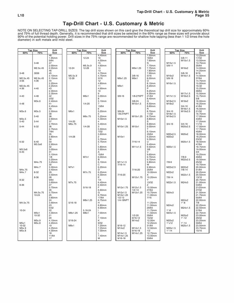
Tap-Drill Chart - U.S. Customary & MetricNOTE ON SELECTING TAP-DRILL SIZES: The tap drill sizes shown on this card give the theoretical tap drill size for approximately 60%and 75% of full thread depth. Generally, it is recommended that drill sizes be selected in the 60% range as these sizes will provide about90% of the potential holding power. Drill sizes in the 75% range are recommended for shallow hole tapping (less than 1 1/2 times the holediameter) in soft metals and mild steel.
Tap Size DrillSize60% 75%
481.95mm5/64
3-48 472.00mm
M2.5x.45 2.05mm46
3-48 3056 452.10mm
M2.5x.45 M2.6x.45 2.15mm3-56 4-36 44
2.20mmM2.6x.45 2.25mm4-36 4-40 43
2.30mm2.35mm
4-40 4-48 423/32
M3x.6 2.40mm4-48 41
2.45mm40
M3x.6 M3x.5 2.50mm39
5-40 38M3x.5 2.60mm5-40 5-44 37
2.70mm5-44 6-32 36
2.75mm7/64352.80mm34
6-32 6-40 33M3.5x6 2.90mm
32M3.5x6 3.00mm6-40 31
3.10mm1/83.20mm
M4x.75 3.25mm30
M4x.7 3.30mmM4x.75 3.40mmM4x.7 8-32 29
3.50mm8-36 28
8-32 9/643.60mm
8-36 273.70mm26
M4.5x.75 3.75mm10-24 25
3.80mm24
M4.5x.75 3.90mm235/32
10-24 22M5x1 4.00mm10-32 21
20M5x.9 4.10mm
M5x1 M5x.8 4.20mm10-32 19M5x.9 4.25mmM5x.8 4.30mm
1811/6417
Tap Size DrillSize60% 75%
4.40mm12-24 16
4.50mm15
M5.5x.9 4.60mm12-24 12-28 14
134.70mm
M5.5x.9 4.75mm12-28 3/16
124.80mm114.90mm109
M6x1 5.00mm85.10mm
1/4-20 713/646
M6x1 5.20mm5
M6x.75 5.25mm5.30mm
1/4-20 4M6x.75 5.40mm
1/4-28 35.50mm7/325.60mm
1/4-28 25.70mm5.75mm15.80mm5.90mmA15/64
M7x1 6.00mmB6.10mmC
M7x1 6.20mmD
M7x.75 6.25mm6.30mmE1/4
M7x.75 6.40mm6.50mm
5/16-18 F6.60mmG6.70mm17/64
M8x1.25 6.75mm5/16-18 H
6.80mm6.90mm
5.16-24 IM8x1.25 M8x1 7.00mm
J7.10mm
5/16-24 K9/32
M8x1 7.20mm7.25mm7.30mmL7.40mmM
Tap Size DrillSize60% 75%
7.50mm19/647.60mmN7.70mm
M9x1.25 7.75mm7.80mm7.90mm
3/8-16 5/16M9x1.25 M9x1 8.00mm
O8.10mm
M9x1 8.20mmP8.25mm8.30mm
3/8-16 1/8-27NPT 21/648.40mm
3/8-24 QM10x1.5 8.50mm
8.60mmR
3/8-24 8.70mm1/8-27NPT 11/32
M10x1.25 8.75mmM10x1.5 8.80mm
S8.90mm
M10x1.25 M10x1 9.00mmT9.10mm23/64
M10x1 9.20mm9.30mm
7/16-14 U9.40mm
M11x1.5 9.50mm3/8V9.60mm9.70mm9.75mm
M11x1.5 9.80mm7/16-14 W
9.90mm7/16-20 25/64
10.00mm7/16-20 X
M12x1.75 10.20mmY13/32Z
M12x1.75 M12x1.5 10.50mm1/2-13 27/64
M12x1.5 M12x1.25 10.75mmM12x1.25 11.00mm1/2-13 7/161/4-18NPT
11.25mm11.50mm29/6411.75mm11.50mm
1/2-20 29/649/16-12 15/32M14x2 12.00m
12.25mm9/16-12 31/64M14x2 M14x1.5 12.50mm
9/16-18 1/2M14x1.5 M14x1.25 12.75mmM14x1.25 13.00mm9/16-18 33/64
Tap Size DrillSize60% 75%
13.25mm5/8-11 17/32M15x1.5 13.50mm
M15x1.5 13.75mm5/8-11 35/64
M16x2 14.00mm14.25mm
5/8-18 9/16M16x2 M16x1.5 14.50mm5/8-18 37/64
14.75mmM16x1.5 15.00mm
19.3215.25mm39/64
M17x1.5 15.50mmM17x1.5 M18x2.5 15.75mm
5/8M18x2.5 M18x2 16.00mmM18x2 16.25mm
3/4-10 41/64M18x1.5 16.50mm
3/4-10 M19x2.5 21/32M18x1.5 16.75mmM19x2.5 17.00mm
43/6417.25mm
3/4-16 3/4-16 11/16M20x2.5 17.50mm
17.75mm45/64
M20x2.5 M20x2 18.00mmM20x2 18.25mm
23/32M20x1.5 18.50mm
47/64M20x1.5 18.75mm
19.00mm3/419.25mm
7/8-9 49/64M22x2.5 19.50mm
7/8-9 25/3219.75mm
M22x2.5 M22x2 20.00mm7/8-14 51/64
M22x2 20.25mmM22x1.5 20.50mm
7/8-14 13/1620.75mm
M22x1.5 M24x3 21.00mm53/6421/25mm27/32
M24x3 21.50mm21.75mm55/64
M24x2 22.00mm1″-8 7/8
M24x2 22.25mmM24x1.5 22.50mm
1″-8 57/64M24x1.5 22.75mm
M25x2 23.00mm1″-12 29/32
M25x2 23.25mm1″x12 1″-14 59/64
M25x1.5 23.50mmM20x1.5 23.75mm1″-14 15/16
Tap-Drill Chart - U.S. Customary & MetricL10 Page 55
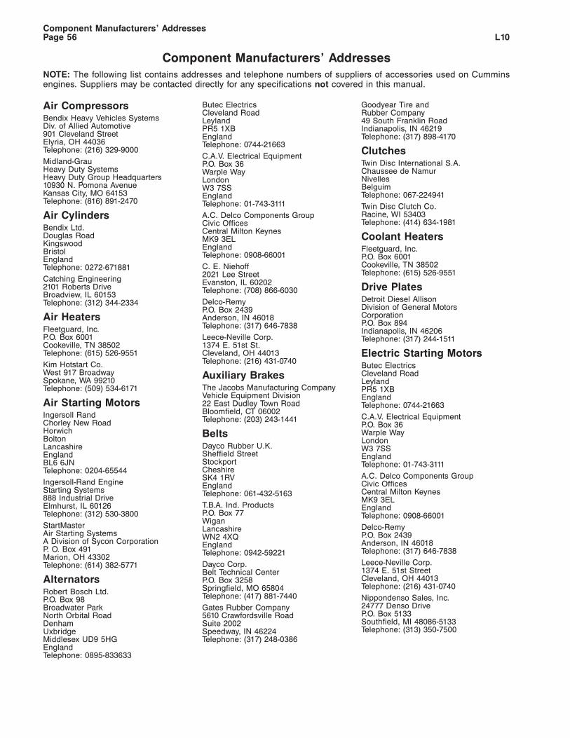
Component Manufacturers’ Addresses
NOTE: The following list contains addresses and telephone numbers of suppliers of accessories used on Cumminsengines. Suppliers may be contacted directly for any specifications not covered in this manual.
Air CompressorsBendix Heavy Vehicles SystemsDiv. of Allied Automotive901 Cleveland StreetElyria, OH 44036Telephone: (216) 329-9000
Midland-GrauHeavy Duty SystemsHeavy Duty Group Headquarters10930 N. Pomona AvenueKansas City, MO 64153Telephone: (816) 891-2470
Air CylindersBendix Ltd.Douglas RoadKingswoodBristolEnglandTelephone: 0272-671881
Catching Engineering2101 Roberts DriveBroadview, IL 60153Telephone: (312) 344-2334
Air HeatersFleetguard, Inc.P.O. Box 6001Cookeville, TN 38502Telephone: (615) 526-9551
Kim Hotstart Co.West 917 BroadwaySpokane, WA 99210Telephone: (509) 534-6171
Air Starting MotorsIngersoll RandChorley New RoadHorwichBoltonLancashireEnglandBL6 6JNTelephone: 0204-65544
Ingersoll-Rand EngineStarting Systems888 Industrial DriveElmhurst, IL 60126Telephone: (312) 530-3800
StartMasterAir Starting SystemsA Division of Sycon CorporationP. O. Box 491Marion, OH 43302Telephone: (614) 382-5771
AlternatorsRobert Bosch Ltd.P.O. Box 98Broadwater ParkNorth Orbital RoadDenhamUxbridgeMiddlesex UD9 5HGEnglandTelephone: 0895-833633
Butec ElectricsCleveland RoadLeylandPR5 1XBEnglandTelephone: 0744-21663
C.A.V. Electrical EquipmentP.O. Box 36Warple WayLondonW3 7SSEnglandTelephone: 01-743-3111
A.C. Delco Components GroupCivic OfficesCentral Milton KeynesMK9 3ELEnglandTelephone: 0908-66001
C. E. Niehoff2021 Lee StreetEvanston, IL 60202Telephone: (708) 866-6030
Delco-RemyP.O. Box 2439Anderson, IN 46018Telephone: (317) 646-7838
Leece-Neville Corp.1374 E. 51st St.Cleveland, OH 44013Telephone: (216) 431-0740
Auxiliary BrakesThe Jacobs Manufacturing CompanyVehicle Equipment Division22 East Dudley Town RoadBloomfield, CT 06002Telephone: (203) 243-1441
BeltsDayco Rubber U.K.Sheffield StreetStockportCheshireSK4 1RVEnglandTelephone: 061-432-5163
T.B.A. Ind. ProductsP.O. Box 77WiganLancashireWN2 4XQEnglandTelephone: 0942-59221
Dayco Corp.Belt Technical CenterP.O. Box 3258Springfield, MO 65804Telephone: (417) 881-7440
Gates Rubber Company5610 Crawfordsville RoadSuite 2002Speedway, IN 46224Telephone: (317) 248-0386
Goodyear Tire andRubber Company49 South Franklin RoadIndianapolis, IN 46219Telephone: (317) 898-4170
ClutchesTwin Disc International S.A.Chaussee de NamurNivellesBelguimTelephone: 067-224941
Twin Disc Clutch Co.Racine, WI 53403Telephone: (414) 634-1981
Coolant HeatersFleetguard, Inc.P.O. Box 6001Cookeville, TN 38502Telephone: (615) 526-9551
Drive PlatesDetroit Diesel AllisonDivision of General MotorsCorporationP.O. Box 894Indianapolis, IN 46206Telephone: (317) 244-1511
Electric Starting MotorsButec ElectricsCleveland RoadLeylandPR5 1XBEnglandTelephone: 0744-21663
C.A.V. Electrical EquipmentP.O. Box 36Warple WayLondonW3 7SSEnglandTelephone: 01-743-3111
A.C. Delco Components GroupCivic OfficesCentral Milton KeynesMK9 3ELEnglandTelephone: 0908-66001
Delco-RemyP.O. Box 2439Anderson, IN 46018Telephone: (317) 646-7838
Leece-Neville Corp.1374 E. 51st StreetCleveland, OH 44013Telephone: (216) 431-0740
Nippondenso Sales, Inc.24777 Denso DriveP.O. Box 5133Southfield, MI 48086-5133Telephone: (313) 350-7500
Component Manufacturers’ AddressesL10Page 56
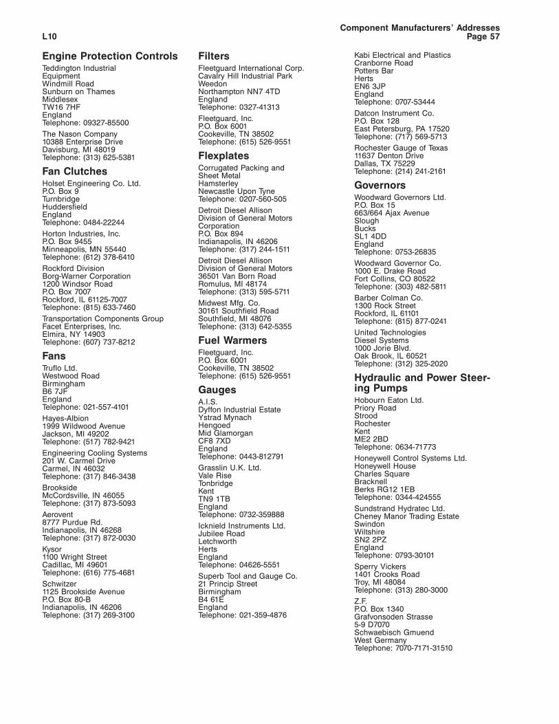
Engine Protection ControlsTeddington IndustrialEquipmentWindmill RoadSunburn on ThamesMiddlesexTW16 7HFEnglandTelephone: 09327-85500
The Nason Company10388 Enterprise DriveDavisburg, MI 48019Telephone: (313) 625-5381
Fan ClutchesHolset Engineering Co. Ltd.P.O. Box 9TurnbridgeHuddersfieldEnglandTelephone: 0484-22244
Horton Industries, Inc.P.O. Box 9455Minneapolis, MN 55440Telephone: (612) 378-6410
Rockford DivisionBorg-Warner Corporation1200 Windsor RoadP.O. Box 7007Rockford, IL 61125-7007Telephone: (815) 633-7460
Transportation Components GroupFacet Enterprises, Inc.Elmira, NY 14903Telephone: (607) 737-8212
FansTruflo Ltd.Westwood RoadBirminghamB6 7JFEnglandTelephone: 021-557-4101
Hayes-Albion1999 Wildwood AvenueJackson, MI 49202Telephone: (517) 782-9421
Engineering Cooling Systems201 W. Carmel DriveCarmel, IN 46032Telephone: (317) 846-3438
BrooksideMcCordsville, IN 46055Telephone: (317) 873-5093
Aerovent8777 Purdue Rd.Indianapolis, IN 46268Telephone: (317) 872-0030
Kysor1100 Wright StreetCadillac, MI 49601Telephone: (616) 775-4681
Schwitzer1125 Brookside AvenueP.O. Box 80-BIndianapolis, IN 46206Telephone: (317) 269-3100
FiltersFleetguard International Corp.Cavalry Hill Industrial ParkWeedonNorthampton NN7 4TDEnglandTelephone: 0327-41313
Fleetguard, Inc.P.O. Box 6001Cookeville, TN 38502Telephone: (615) 526-9551
FlexplatesCorrugated Packing andSheet MetalHamsterleyNewcastle Upon TyneTelephone: 0207-560-505
Detroit Diesel AllisonDivision of General MotorsCorporationP.O. Box 894Indianapolis, IN 46206Telephone: (317) 244-1511
Detroit Diesel AllisonDivision of General Motors36501 Van Born RoadRomulus, MI 48174Telephone: (313) 595-5711
Midwest Mfg. Co.30161 Southfield RoadSouthfield, MI 48076Telephone: (313) 642-5355
Fuel WarmersFleetguard, Inc.P.O. Box 6001Cookeville, TN 38502Telephone: (615) 526-9551
GaugesA.I.S.Dyffon Industrial EstateYstrad MynachHengoedMid GlamorganCF8 7XDEnglandTelephone: 0443-812791
Grasslin U.K. Ltd.Vale RiseTonbridgeKentTN9 1TBEnglandTelephone: 0732-359888
Icknield Instruments Ltd.Jubilee RoadLetchworthHertsEnglandTelephone: 04626-5551
Superb Tool and Gauge Co.21 Princip StreetBirminghamB4 61EEnglandTelephone: 021-359-4876
Kabi Electrical and PlasticsCranborne RoadPotters BarHertsEN6 3JPEnglandTelephone: 0707-53444
Datcon Instrument Co.P.O. Box 128East Petersburg, PA 17520Telephone: (717) 569-5713
Rochester Gauge of Texas11637 Denton DriveDallas, TX 75229Telephone: (214) 241-2161
GovernorsWoodward Governors Ltd.P.O. Box 15663/664 Ajax AvenueSloughBucksSL1 4DDEnglandTelephone: 0753-26835
Woodward Governor Co.1000 E. Drake RoadFort Collins, CO 80522Telephone: (303) 482-5811
Barber Colman Co.1300 Rock StreetRockford, IL 61101Telephone: (815) 877-0241
United TechnologiesDiesel Systems1000 Jorie Blvd.Oak Brook, IL 60521Telephone: (312) 325-2020
Hydraulic and Power Steer-ing PumpsHobourn Eaton Ltd.Priory RoadStroodRochesterKentME2 2BDTelephone: 0634-71773
Honeywell Control Systems Ltd.Honeywell HouseCharles SquareBracknellBerks RG12 1EBTelephone: 0344-424555
Sundstrand Hydratec Ltd.Cheney Manor Trading EstateSwindonWiltshireSN2 2PZEnglandTelephone: 0793-30101
Sperry Vickers1401 Crooks RoadTroy, MI 48084Telephone: (313) 280-3000
Z.F.P.O. Box 1340Grafvonsoden Strasse5-9 D7070Schwaebisch GmuendWest GermanyTelephone: 7070-7171-31510
Component Manufacturers’ AddressesL10 Page 57
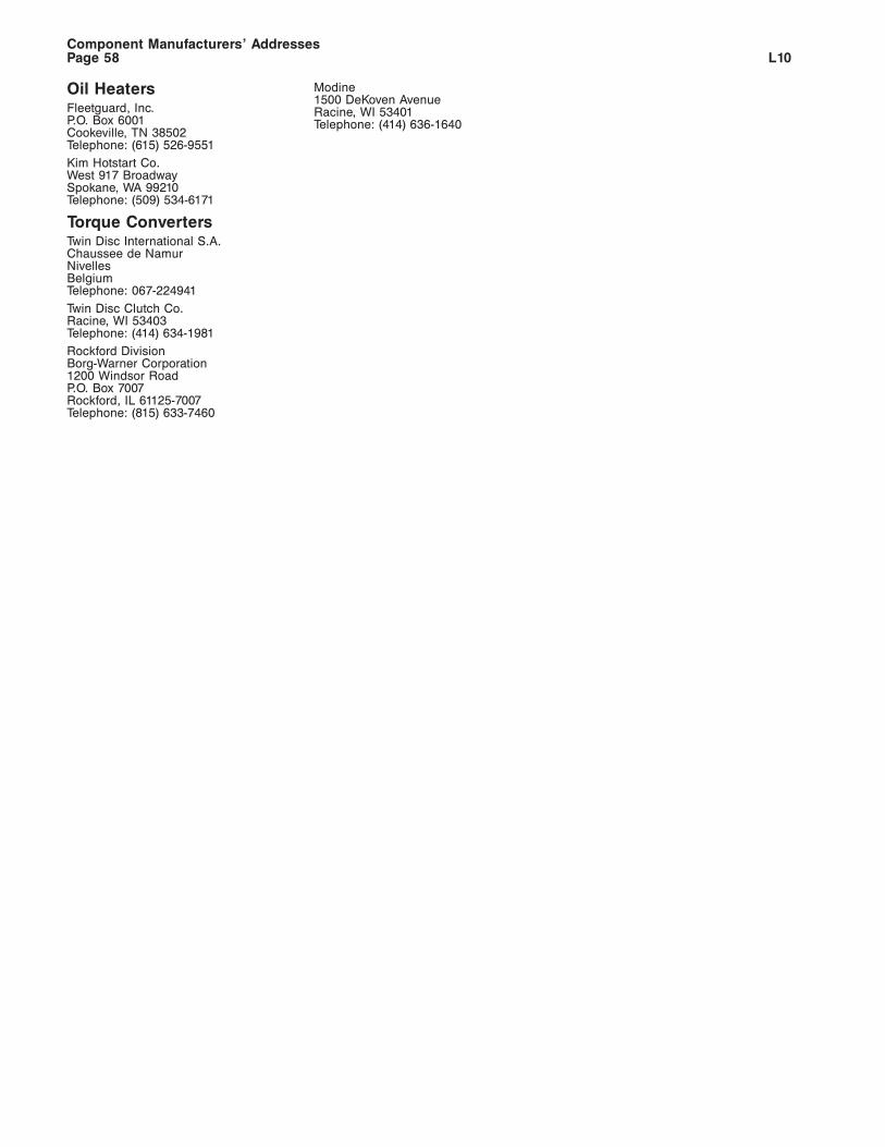
Oil HeatersFleetguard, Inc.P.O. Box 6001Cookeville, TN 38502Telephone: (615) 526-9551
Kim Hotstart Co.West 917 BroadwaySpokane, WA 99210Telephone: (509) 534-6171
Torque ConvertersTwin Disc International S.A.Chaussee de NamurNivellesBelgiumTelephone: 067-224941
Twin Disc Clutch Co.Racine, WI 53403Telephone: (414) 634-1981
Rockford DivisionBorg-Warner Corporation1200 Windsor RoadP.O. Box 7007Rockford, IL 61125-7007Telephone: (815) 633-7460
Modine1500 DeKoven AvenueRacine, WI 53401Telephone: (414) 636-1640
Component Manufacturers’ AddressesL10Page 58
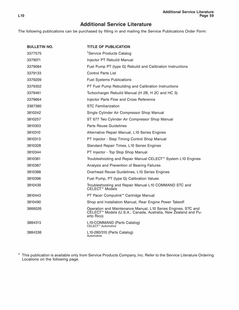
Additional Service Literature
The following publications can be purchased by filling in and mailing the Service Publications Order Form:
BULLETIN NO. TITLE OF PUBLICATION
3377575 1Service Products Catalog
3379071 Injector PT Rebuild Manual
3379084 Fuel Pump PT (type G) Rebuild and Calibration Instructions
3379133 Control Parts List
3379209 Fuel Systems Publications
3379352 PT Fuel Pump Rebuilding and Calibration Instructions
3379461 Turbocharger Rebuild Manual (H 2B, H 2C and HC 3)
3379664 Injector Parts Flow and Cross Reference
3387380 STC Familiarization
3810242 Single Cylinder Air Compressor Shop Manual
3810257 ST 677 Two Cylinder Air Compressor Shop Manual
3810303 Parts Reuse Guidelines
3810310 Alternative Repair Manual, L10 Series Engines
3810313 PT Injector - Step Timing Control Shop Manual
3810328 Standard Repair Times, L10 Series Engines
3810344 PT Injector - Top Stop Shop Manual
3810361 Troubleshooting and Repair Manual CELECT™ System L10 Engines
3810387 Analysis and Prevention of Bearing Failures
3810388 Overhead Reuse Guidelines, L10 Series Engines
3810396 Fuel Pump, PT (type G) Calibration Values
3810439 Troubleshooting and Repair Manual L10 COMMAND STC andCELECT™ Models
3810443 PT Pacer Compulink™ Cartridge Manual
3810490 Shop and Installation Manual, Rear Engine Power Takeoff
3666026 Operation and Maintenance Manual, L10 Series Engines, STC andCELECT™ Models (U.S.A., Canada, Australia, New Zealand and Pu-erto Rico)
3884315 L10-COMMAND (Parts Catalog)CELECT™ Automotive
3884338 L10-280/310 (Parts Catalog)Automotive
1 This publication is available only from Service Products Company, Inc. Refer to the Service Literature OrderingLocations on the following page.
Additional Service LiteratureL10 Page 59
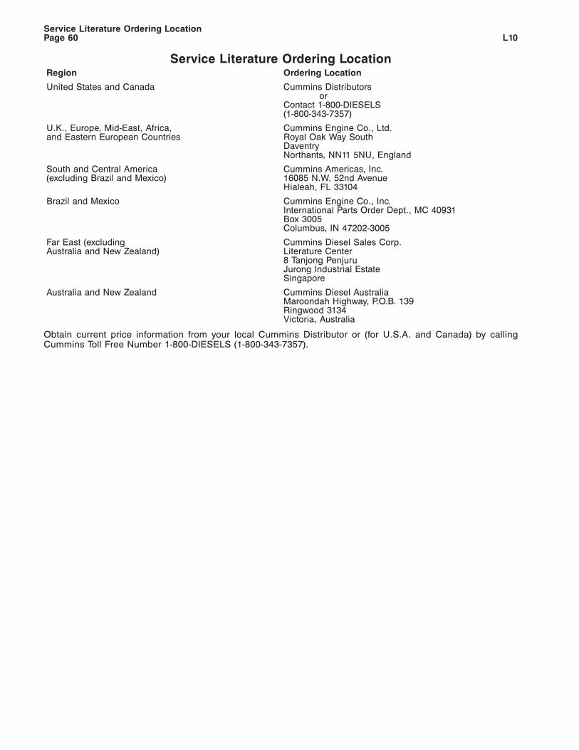
Service Literature Ordering LocationRegion Ordering Location
United States and Canada Cummins Distributorsor
Contact 1-800-DIESELS(1-800-343-7357)
U.K., Europe, Mid-East, Africa,and Eastern European Countries
Cummins Engine Co., Ltd.Royal Oak Way SouthDaventryNorthants, NN11 5NU, England
South and Central America(excluding Brazil and Mexico)
Cummins Americas, Inc.16085 N.W. 52nd AvenueHialeah, FL 33104
Brazil and Mexico Cummins Engine Co., Inc.International Parts Order Dept., MC 40931Box 3005Columbus, IN 47202-3005
Far East (excludingAustralia and New Zealand)
Cummins Diesel Sales Corp.Literature Center8 Tanjong PenjuruJurong Industrial EstateSingapore
Australia and New Zealand Cummins Diesel AustraliaMaroondah Highway, P.O.B. 139Ringwood 3134Victoria, Australia
Obtain current price information from your local Cummins Distributor or (for U.S.A. and Canada) by callingCummins Toll Free Number 1-800-DIESELS (1-800-343-7357).
Service Literature Ordering LocationL10Page 60
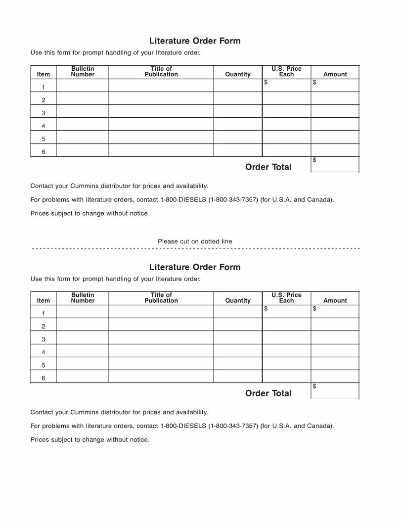
Literature Order Form
Use this form for prompt handling of your literature order.
ItemBulletinNumber
Title ofPublication Quantity
U.S. PriceEach Amount
1$ $
2
3
4
5
6
Order Total$
Contact your Cummins distributor for prices and availability.
For problems with literature orders, contact 1-800-DIESELS (1-800-343-7357) (for U.S.A. and Canada).
Prices subject to change without notice.
Please cut on dotted line- - - - - - - - - - - - - - - - - - - - - - - - - - - - - - - - - - - - - - - - - - - - - - - - - - - - - - - - - - - - - - - - - - - - - - - - - - - - - - - - - - - - - - - -
Literature Order Form
Use this form for prompt handling of your literature order.
ItemBulletinNumber
Title ofPublication Quantity
U.S. PriceEach Amount
1$ $
2
3
4
5
6
Order Total$
Contact your Cummins distributor for prices and availability.
For problems with literature orders, contact 1-800-DIESELS (1-800-343-7357) (for U.S.A. and Canada).
Prices subject to change without notice.
Mail the Literature Order Form along with your ship-to address to your nearest Cummins distributor.
FROM:
Name:
Street Address:
City: State: Zip Code:
Country:
SHIP TO: (Name and address where literature is to be shipped)
Name:
Street Address:
City: State: Zip Code:
Country:
Please cut on dotted line- - - - - - - - - - - - - - - - - - - - - - - - - - - - - - - - - - - - - - - - - - - - - - - - - - - - - - - - - - - - - - - - - - - - - - - - - - - - - - - - - - - - - - - -
Mail the Literature Order Form along with your ship-to address to your nearest Cummins distributor.
FROM:
Name:
Street Address:
City: State: Zip Code:
Country:
SHIP TO: (Name and address where literature is to be shipped)
Name:
Street Address:
City: State: Zip Code:
Country:
41308
NO POSTAGENECESSARYIF MAILED
IN THEUNITED STATES
BUSINESS REPLY MAILFIRST CLASS PERMIT NO. 15, COLUMBUS INDIANA
–POSTAGE WILL BE PAID BY ADDRESSEE—
CUMMINS ENGINE COMPANY, INC.MAIL CODEBOX 3005COLUMBUS, IN 47202-3005
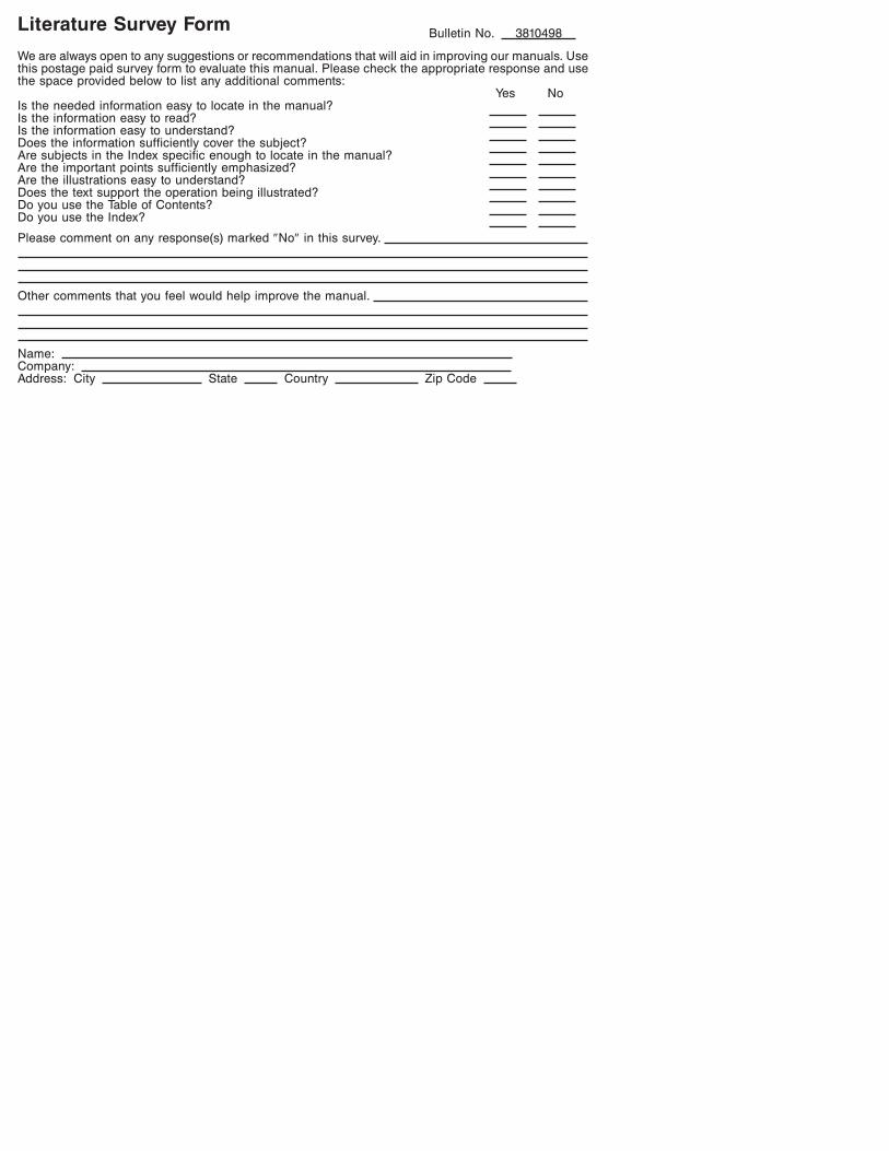
Literature Survey FormBulletin No. 3810498
We are always open to any suggestions or recommendations that will aid in improving our manuals. Usethis postage paid survey form to evaluate this manual. Please check the appropriate response and usethe space provided below to list any additional comments:
Yes NoIs the needed information easy to locate in the manual?Is the information easy to read?Is the information easy to understand?Does the information sufficiently cover the subject?Are subjects in the Index specific enough to locate in the manual?Are the important points sufficiently emphasized?Are the illustrations easy to understand?Does the text support the operation being illustrated?Do you use the Table of Contents?Do you use the Index?
Please comment on any response(s) marked ″No″ in this survey.
Other comments that you feel would help improve the manual.
Name:Company:Address: City State Country Zip Code
Cummins Engine Company, Inc.Box 3005Columbus, IN, U.S.A., 47202-3005Cable: CUMDIEX COLUMBUS
Cummins Engine Company Ltd.46-50 Coombe RoadNew Malden,Surrey KT3 4QL,EnglandCable: CUMEUR GRegistration No. 573951 England
Bulletin No. 3810498-02Printed in U.S.A. 12/94 925