3825fan installation
DESCRIPTION
Fan replacement on Cisco 3825TRANSCRIPT
Installing and Upgrading Fans in the Cisco 3825 Series Routers
This document describes how to install or upgrade fans inside your Cisco 3825 series router.
This document is intended for the fan installer who is familiar with electronic circuitry and wiring practices and has experience as an electronic or electromechanical technician.
Note Use this document in conjunction with the following documents:
• Cisco 3800 Series Hardware Installation guide:
http://www.cisco.com/en/US/docs/routers/access/3800/hardware/installation/guide/hw.html
• Cisco 2800 Series and Cisco 3800 Series Integrated Services Routers Regulatory Compliance and Safety Information document:
http://www.cisco.com/en/US/docs/routers/access/2800/hardware/rcsi/2838rcsi.html
If you have questions or need help, see the “Obtaining Documentation, Obtaining Support, and Security Guidelines” section on page 18.
This document contains the following sections:
• Safety Warnings and Guidelines, page 2
• Items in the Fan Replacement Kit, page 10
• Required Tools and Equipment, page 10
• Location of the Cisco 3825 Router Fans, page 11
• Upgrading the Cisco 3825 Fan Unit, page 12
• Obtaining Documentation, Obtaining Support, and Security Guidelines, page 18.
Americas Headquarters:
© 2010 Cisco Systems, Inc. All rights reserved.
Cisco Systems, Inc., 170 West Tasman Drive, San Jose, CA 95134-1706 USA

Safety Warnings and Guidelines
Safety Warnings and GuidelinesThis section provides the safety warnings and guidelines for working with the Cisco 3825 series router. It contains the following sections:
• Safety Warnings, page 2
• Safety Guidelines, page 9
• Safety with Electricity, page 9
• Preventing Electrostatic Discharge Damage, page 10
Safety Warnings
Note Use this section in conjunction with the Cisco 2800 Series and Cisco 3800 Series Integrated Services Routers Regulatory Compliance and Safety Information document:
http://www.cisco.com/en/US/docs/routers/access/2800/hardware/rcsi/2838rcsi.html
2Installing and Upgrading Fans in the Cisco 3825 Series Routers
78-18642-01B0

Safety Warnings and Guidelines
Statement 1071—Warning Definition
Warning IMPORTANT SAFETY INSTRUCTIONS
This warning symbol means danger. You are in a situation that could cause bodily injury. Before you work on any equipment, be aware of the hazards involved with electrical circuitry and be familiar with standard practices for preventing accidents. Use the statement number provided at the end of each warning to locate its translation in the translated safety warnings that accompanied this device. Statement 1071
SAVE THESE INSTRUCTIONS
Waarschuwing BELANGRIJKE VEILIGHEIDSINSTRUCTIES
Dit waarschuwingssymbool betekent gevaar. U verkeert in een situatie die lichamelijk letsel kan veroorzaken. Voordat u aan enige apparatuur gaat werken, dient u zich bewust te zijn van de bij elektrische schakelingen betrokken risico's en dient u op de hoogte te zijn van de standaard praktijken om ongelukken te voorkomen. Gebruik het nummer van de verklaring onderaan de waarschuwing als u een vertaling van de waarschuwing die bij het apparaat wordt geleverd, wilt raadplegen.
BEWAAR DEZE INSTRUCTIES
Varoitus TÄRKEITÄ TURVALLISUUSOHJEITA
Tämä varoitusmerkki merkitsee vaaraa. Tilanne voi aiheuttaa ruumiillisia vammoja. Ennen kuin käsittelet laitteistoa, huomioi sähköpiirien käsittelemiseen liittyvät riskit ja tutustu onnettomuuksien yleisiin ehkäisytapoihin. Turvallisuusvaroitusten käännökset löytyvät laitteen mukana toimitettujen käännettyjen turvallisuusvaroitusten joukosta varoitusten lopussa näkyvien lausuntonumeroiden avulla.
SÄILYTÄ NÄMÄ OHJEET
Attention IMPORTANTES INFORMATIONS DE SÉCURITÉ
Ce symbole d'avertissement indique un danger. Vous vous trouvez dans une situation pouvant entraîner des blessures ou des dommages corporels. Avant de travailler sur un équipement, soyez conscient des dangers liés aux circuits électriques et familiarisez-vous avec les procédures couramment utilisées pour éviter les accidents. Pour prendre connaissance des traductions des avertissements figurant dans les consignes de sécurité traduites qui accompagnent cet appareil, référez-vous au numéro de l'instruction situé à la fin de chaque avertissement.
CONSERVEZ CES INFORMATIONS
Warnung WICHTIGE SICHERHEITSHINWEISE
Dieses Warnsymbol bedeutet Gefahr. Sie befinden sich in einer Situation, die zu Verletzungen führen kann. Machen Sie sich vor der Arbeit mit Geräten mit den Gefahren elektrischer Schaltungen und den üblichen Verfahren zur Vorbeugung vor Unfällen vertraut. Suchen Sie mit der am Ende jeder Warnung angegebenen Anweisungsnummer nach der jeweiligen Übersetzung in den übersetzten Sicherheitshinweisen, die zusammen mit diesem Gerät ausgeliefert wurden.
BEWAHREN SIE DIESE HINWEISE GUT AUF.
3Installing and Upgrading Fans in the Cisco 3825 Series Routers
78-18642-01B0

Safety Warnings and Guidelines
Avvertenza IMPORTANTI ISTRUZIONI SULLA SICUREZZA
Questo simbolo di avvertenza indica un pericolo. La situazione potrebbe causare infortuni alle persone. Prima di intervenire su qualsiasi apparecchiatura, occorre essere al corrente dei pericoli relativi ai circuiti elettrici e conoscere le procedure standard per la prevenzione di incidenti. Utilizzare il numero di istruzione presente alla fine di ciascuna avvertenza per individuare le traduzioni delle avvertenze riportate in questo documento.
CONSERVARE QUESTE ISTRUZIONI
Advarsel VIKTIGE SIKKERHETSINSTRUKSJONER
Dette advarselssymbolet betyr fare. Du er i en situasjon som kan føre til skade på person. Før du begynner å arbeide med noe av utstyret, må du være oppmerksom på farene forbundet med elektriske kretser, og kjenne til standardprosedyrer for å forhindre ulykker. Bruk nummeret i slutten av hver advarsel for å finne oversettelsen i de oversatte sikkerhetsadvarslene som fulgte med denne enheten.
TA VARE PÅ DISSE INSTRUKSJONENE
Aviso INSTRUÇÕES IMPORTANTES DE SEGURANÇA
Este símbolo de aviso significa perigo. Você está em uma situação que poderá ser causadora de lesões corporais. Antes de iniciar a utilização de qualquer equipamento, tenha conhecimento dos perigos envolvidos no manuseio de circuitos elétricos e familiarize-se com as práticas habituais de prevenção de acidentes. Utilize o número da instrução fornecido ao final de cada aviso para localizar sua tradução nos avisos de segurança traduzidos que acompanham este dispositivo.
GUARDE ESTAS INSTRUÇÕES
¡Advertencia! INSTRUCCIONES IMPORTANTES DE SEGURIDAD
Este símbolo de aviso indica peligro. Existe riesgo para su integridad física. Antes de manipular cualquier equipo, considere los riesgos de la corriente eléctrica y familiarícese con los procedimientos estándar de prevención de accidentes. Al final de cada advertencia encontrará el número que le ayudará a encontrar el texto traducido en el apartado de traducciones que acompaña a este dispositivo.
GUARDE ESTAS INSTRUCCIONES
Varning! VIKTIGA SÄKERHETSANVISNINGAR
Denna varningssignal signalerar fara. Du befinner dig i en situation som kan leda till personskada. Innan du utför arbete på någon utrustning måste du vara medveten om farorna med elkretsar och känna till vanliga förfaranden för att förebygga olyckor. Använd det nummer som finns i slutet av varje varning för att hitta dess översättning i de översatta säkerhetsvarningar som medföljer denna anordning.
SPARA DESSA ANVISNINGAR
4Installing and Upgrading Fans in the Cisco 3825 Series Routers
78-18642-01B0

Safety Warnings and Guidelines
5Installing and Upgrading Fans in the Cisco 3825 Series Routers
78-18642-01B0
Safety Warnings and Guidelines
Aviso INSTRUÇÕES IMPORTANTES DE SEGURANÇA
Este símbolo de aviso significa perigo. Você se encontra em uma situação em que há risco de lesões corporais. Antes de trabalhar com qualquer equipamento, esteja ciente dos riscos que envolvem os circuitos elétricos e familiarize-se com as práticas padrão de prevenção de acidentes. Use o número da declaração fornecido ao final de cada aviso para localizar sua tradução nos avisos de segurança traduzidos que acompanham o dispositivo.
GUARDE ESTAS INSTRUÇÕES
Advarsel VIGTIGE SIKKERHEDSANVISNINGER
Dette advarselssymbol betyder fare. Du befinder dig i en situation med risiko for legemesbeskadigelse. Før du begynder arbejde på udstyr, skal du være opmærksom på de involverede risici, der er ved elektriske kredsløb, og du skal sætte dig ind i standardprocedurer til undgåelse af ulykker. Brug erklæringsnummeret efter hver advarsel for at finde oversættelsen i de oversatte advarsler, der fulgte med denne enhed.
GEM DISSE ANVISNINGER
6Installing and Upgrading Fans in the Cisco 3825 Series Routers
78-18642-01B0

Safety Warnings and Guidelines
7Installing and Upgrading Fans in the Cisco 3825 Series Routers
78-18642-01B0

Safety Warnings and Guidelines
Warning Do not touch the power supply when the power cord is connected. For systems with a power switch, line voltages are present within the power supply even when the power switch is off and the power cord is connected. For systems without a power switch, line voltages are present within the power supply when the power cord is connected. Statement 4
Warning Do not work on the system or connect or disconnect cables during periods of lightning activity. Statement 1001
Warning Before opening the chassis, disconnect the telephone-network cables to avoid contact with telephone-network voltages. Statement 1041
Warning Network hazardous voltages are present in the BRI cable. If you detach the BRI cable, detach the end away from the router first to avoid possible electric shock. Network hazardous voltages also are present on the system card in the area of the BRI port (RJ-45 connector), regardless of when power is turned off. Statement 44
Warning Before working on a chassis or working near power supplies, unplug the power cord on AC units; disconnect the power at the circuit breaker on DC units. Statement 12
Warning When installing the unit, always make the ground connection first and disconnect it last. Statement 42
8Installing and Upgrading Fans in the Cisco 3825 Series Routers
78-18642-01B0

Safety Warnings and Guidelines
Warning Before working on equipment that is connected to power lines, remove jewelry (including rings, necklaces, and watches). Metal objects will heat up when connected to power and ground and can cause serious burns or weld the metal object to the terminals. Statement 43
Warning Do not touch the power supply when the power cord is connected. For systems with a power switch, line voltages are present within the power supply even when the power switch is off and the power cord is connected. For systems without a power switch, line voltages are present within the power supply when the power cord is connected. Statement 4
Warning Before performing any of the following procedures, ensure that power is removed from the DC circuit. Statement 1003
Safety GuidelinesFollow these guidelines to ensure general safety:
• Keep the chassis area clear and dust-free during and after installation.
• Place the removed chassis cover in a safe place.
• Keep tools away from walk areas where you or others could fall over them.
• Do not wear loose clothing that may get caught in the chassis. Fasten your tie or scarf and roll up your sleeves.
• Wear safety glasses when working under conditions that may be hazardous to your eyes.
• Do not perform any action that creates a potential hazard to people or makes the equipment unsafe.
Safety with Electricity
Warning Before working on equipment that is connected to power lines, remove jewelry (including rings, necklaces, and watches). Metal objects will heat up when connected to power and ground and can cause serious burns or weld the metal object to the terminals. Statement 43
Follow these guidelines when working on equipment powered by electricity:
• Locate the room’s emergency power-off switch. Then, if an electrical accident occurs, you can quickly shut the power off.
• Before working on the system, turn off the power and unplug the power cord.
• Disconnect all power.
• Do not work alone if potentially hazardous conditions exist.
• Look carefully for possible hazards in your work area, such as moist floors, ungrounded power extension cables, and missing safety grounds.
• Never assume that power is disconnected from a circuit. Always check.
9Installing and Upgrading Fans in the Cisco 3825 Series Routers
78-18642-01B0
Items in the Fan Replacement Kit
• If an electrical accident occurs, proceed as follows:
– Use caution, and do not become a victim yourself.
– Turn off power to the system.
– If possible, send another person to get medical aid. Otherwise, determine the condition of the victim and then call for help.
Preventing Electrostatic Discharge DamageElectrostatic discharge (ESD) can damage equipment and impair electrical circuitry. It occurs when electronic printed circuit cards are improperly handled and can result in complete or intermittent failures. Always follow ESD-prevention procedures when removing and replacing cards. Ensure that the router chassis is electrically connected to earth ground. Wear an ESD-preventive wrist strap, ensuring that it makes good skin contact. Connect the clip to an unpainted surface of the chassis frame to safely channel unwanted ESD voltages to ground. To properly guard against ESD damage and shocks, the wrist strap and cord must operate effectively. If no wrist strap is available, ground yourself by touching the metal part of the chassis.
Caution For safety, periodically check the resistance value of the antistatic strap, which should be between 1 and 10 megohms (Mohms).
Items in the Fan Replacement Kit The fan replacement kit contains the following items:
• Fan unit (three fans connected together as one unit)
• Additional replacement screws (a few extra screws are provided in case you misplace the original screws)
• Installing and Upgrading Fans in the Cisco 3825 Series Routers document (this document)
Required Tools and EquipmentInstallation might require some tools and equipment that are not provided as standard equipment with the router. The following tools and parts are required for a typical router installation:
• Number 2 Phillips screwdriver
• ESD-preventive wrist strap
• Antistatic mat
10Installing and Upgrading Fans in the Cisco 3825 Series Routers
78-18642-01B0
Location of the Cisco 3825 Router Fans
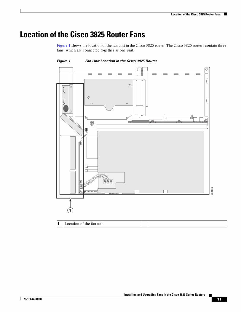
Location of the Cisco 3825 Router FansFigure 1 shows the location of the fan unit in the Cisco 3825 router. The Cisco 3825 routers contain three fans, which are connected together as one unit.
Figure 1 Fan Unit Location in the Cisco 3825 Router
1 Location of the fan unit
2804
741
11Installing and Upgrading Fans in the Cisco 3825 Series Routers
78-18642-01B0
Upgrading the Cisco 3825 Fan Unit
Upgrading the Cisco 3825 Fan UnitThe fan unit and cabling for the Cisco 3825 router are contained inside the chassis.
Note The fan unit upgrade procedure will take approximately one hour.
To upgrade the fan unit, complete these procedures:
• Removing the Router Cover, page 12
• Removing the Fan Unit, page 14
• Installing the Fan Unit, page 16
• Replacing the Router Cover, page 18
Removing the Router CoverTo access the Cisco 3825 fan unit, you must first remove the router cover. To remove the router cover, complete the steps that follow. You will need a number 2 Phillips screwdriver.
If your router uses AC or DC power, observe the following warning:
Warning Do not touch the power supply when the power cord is connected. For systems with a power switch, line voltages are present within the power supply even when the power switch is off and the power cord is connected. For systems without a power switch, line voltages are present within the power supply when the power cord is connected. Statement 4
If your router uses DC power, observe the following warning:
Warning Before performing any of the following procedures, ensure that power is removed from the DC circuit. Statement 1003
Caution Before removing the cover, make sure that the flash memory card ejector button is flush with the front panel. If the button projects from the panel, removing the cover can damage it.
Step 1 Power down the router and disconnect the power cord from the front of the router.
Warning Before opening the unit, disconnect the telephone-network cables to avoid contact with telephone-network voltages. Statement 1041
Step 2 Disconnect all network interface cables from the back panel of the router.
Step 3 Remove the router from the rack. Remove the rack-mounting brackets from the router, using the number 2 Phillips screwdriver.
Step 4 Place the router on a flat surface. Remove the two screws from the top of the router and set them aside in a safe place.
12Installing and Upgrading Fans in the Cisco 3825 Series Routers
78-18642-01B0
Upgrading the Cisco 3825 Fan Unit
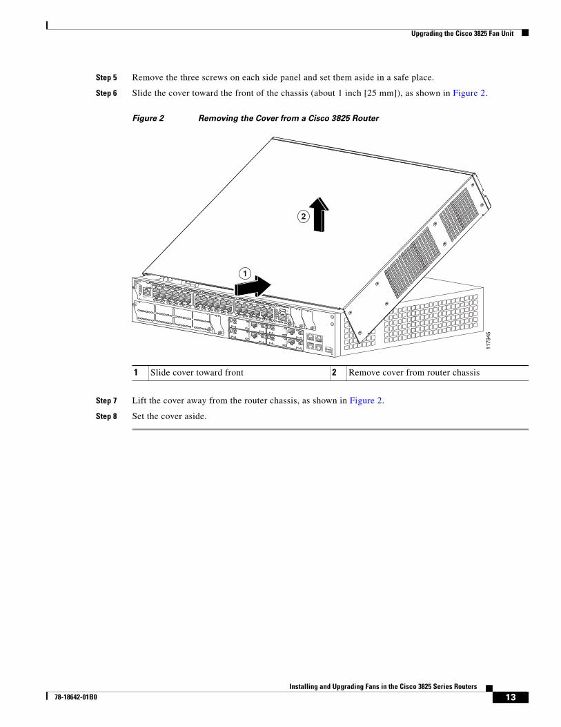
Step 5 Remove the three screws on each side panel and set them aside in a safe place.
Step 6 Slide the cover toward the front of the chassis (about 1 inch [25 mm]), as shown in Figure 2.
Figure 2 Removing the Cover from a Cisco 3825 Router
Step 7 Lift the cover away from the router chassis, as shown in Figure 2.
Step 8 Set the cover aside.
1 Slide cover toward front 2 Remove cover from router chassis
1179
45
EN
NMD-ESW-36
23x 5x
FastEthernet Ports
22x 4x 21x 3x 20x 2x 19x 1x 18x 0x
29x 11x 28x 10x 27x 9x 26x 8x 25x 17 24x 6x
35x 17x 34x 16x 33x 15x 32x 14x 31x 13x 30x 12x
ExtPwr
-48V
0x
18x
GE010/100/1000Base-Tx
35x
10/100/1000Base-Tx
GE1
17x
1
2
13Installing and Upgrading Fans in the Cisco 3825 Series Routers
78-18642-01B0
Upgrading the Cisco 3825 Fan Unit
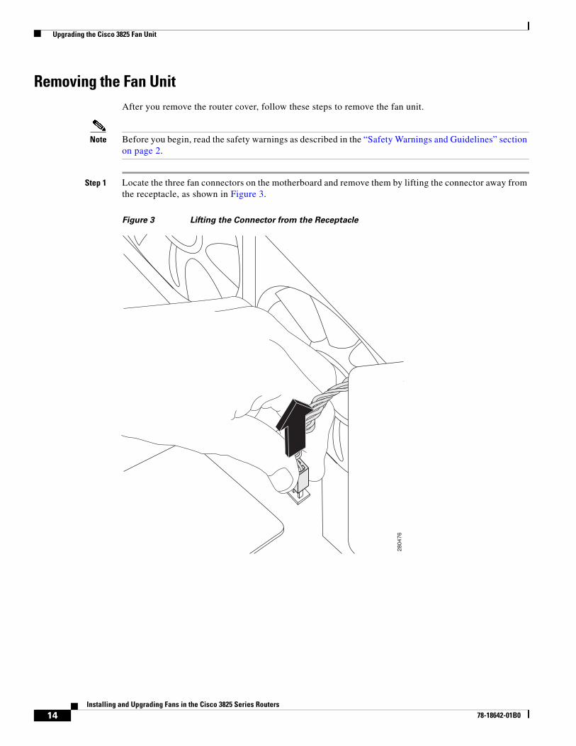
Removing the Fan UnitAfter you remove the router cover, follow these steps to remove the fan unit.
Note Before you begin, read the safety warnings as described in the “Safety Warnings and Guidelines” section on page 2.
Step 1 Locate the three fan connectors on the motherboard and remove them by lifting the connector away from the receptacle, as shown in Figure 3.
Figure 3 Lifting the Connector from the Receptacle
280476
14Installing and Upgrading Fans in the Cisco 3825 Series Routers
78-18642-01B0
Upgrading the Cisco 3825 Fan Unit
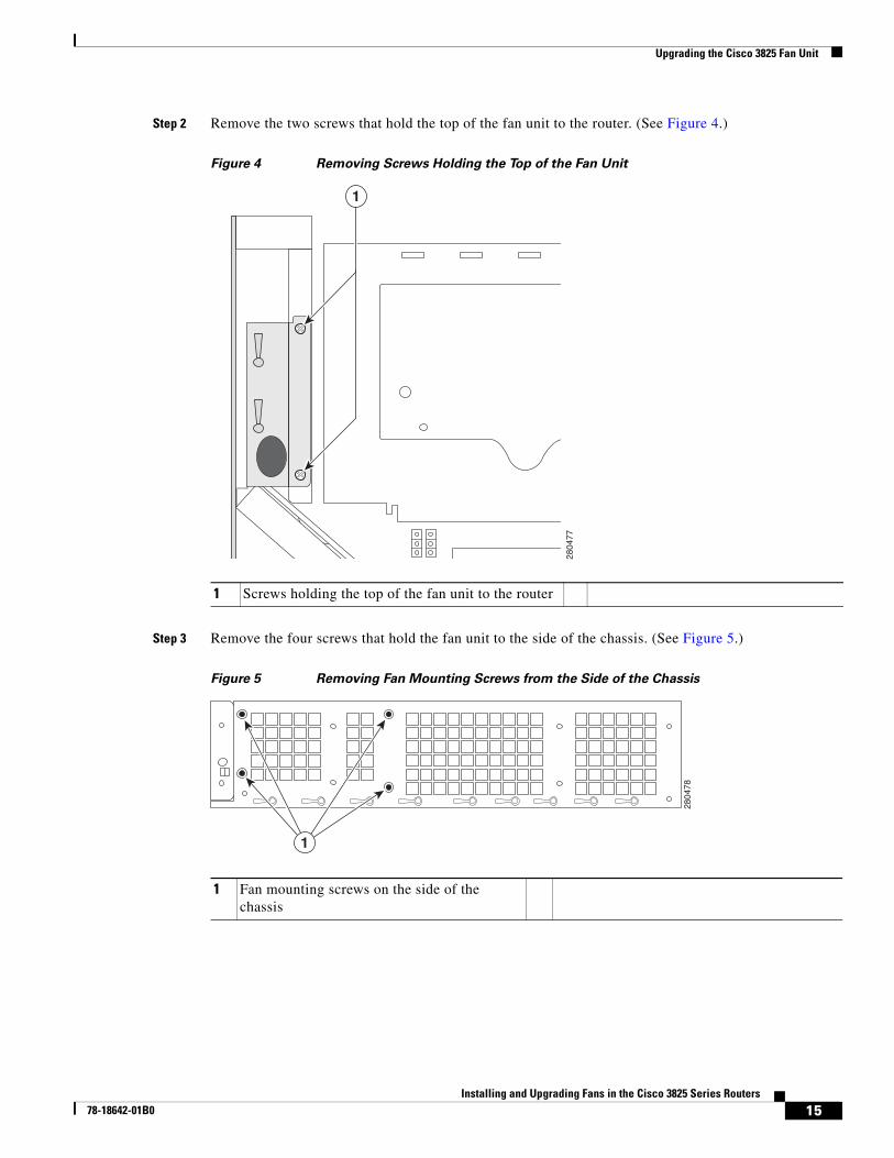
Step 2 Remove the two screws that hold the top of the fan unit to the router. (See Figure 4.)
Figure 4 Removing Screws Holding the Top of the Fan Unit
Step 3 Remove the four screws that hold the fan unit to the side of the chassis. (See Figure 5.)
Figure 5 Removing Fan Mounting Screws from the Side of the Chassis
1 Screws holding the top of the fan unit to the router
2804
77
1
1 Fan mounting screws on the side of the chassis
1
280478
15Installing and Upgrading Fans in the Cisco 3825 Series Routers
78-18642-01B0

Upgrading the Cisco 3825 Fan Unit
Step 4 Remove the two screws that hold the fan unit to the front of the chassis. (See Figure 6.)
Figure 6 Removing Fan Mounting Screws from the Front of the Chassis
Step 5 Lift the fan unit out of the chassis.
Installing the Fan UnitFollow these steps to install the fan unit.
Note Before you begin, read the safety warnings as described in the “Safety Warnings and Guidelines” section on page 2.
1 Fan mounting screws on the front of the chassis
280479
1
16Installing and Upgrading Fans in the Cisco 3825 Series Routers
78-18642-01B0

Upgrading the Cisco 3825 Fan Unit
Step 1 Lower the fan unit down and onto the chassis floor.
Step 2 Attach fan 1 to the J4 connector on the motherboard. (See number 1 and 2 in Figure 7.)
Figure 7 Attaching Fan Cable to the J Connectors
Step 3 Attach fan 2 to the J18 connector on the motherboard. (See number 3 and 4 in Figure 7.)
Step 4 Attach fan 3 to the J25 connector on the motherboard. (See number 5 and 6 in Figure 7.)
Caution Orient the fan connectors correctly before you insert them. Incorrect orientation can damage the connector pins.
Step 5 Reinstall the two screws on the front of the chassis. (See Figure 6 on page 16.)
Step 6 Reinstall the four screws on the side of the chassis. (See Figure 5 on page 15.)
Step 7 Reinstall the two screws on the top of the fan unit. (See Figure 4 on page 15.)
1 Fan 1 2 Fan 1 to J4 connector
3 Fan 2 4 Fan 2 to J18 connector
5 Fan 3 6 Fan 3 to J25 connector
1 2 43 65
2804
75
17Installing and Upgrading Fans in the Cisco 3825 Series Routers
78-18642-01B0

Obtaining Documentation, Obtaining Support, and Security Guidelines
Replacing the Router CoverFollow these steps to replace the cover.
Note Before you begin, read the safety warnings as described in the “Safety Warnings and Guidelines” section on page 2.
Step 1 Place the router on a flat surface, with the front panel facing you.
Step 2 Place the cover on the base, with about 1 inch (25 mm) of clearance between the cover and the back panel.
Step 3 Slide the cover back onto the base, making sure that the hook at the back edge of the cover, near the left side, fits underneath the card cage on the back panel of the router.
Caution When replacing the cover, do not pinch the wires.
Step 4 Reinstall the rack-mounting brackets, and then reinstall the router in the rack.
Step 5 Reconnect power and network interface cables.
Step 6 Power up the router, and verify that the alarms and warnings disappear.
Obtaining Documentation, Obtaining Support, and Security Guidelines
For information on obtaining documentation, obtaining support, providing documentation feedback, security guidelines, and also recommended aliases and general Cisco documents, see the monthly What’s New in Cisco Product Documentation, which also lists all new and revised Cisco technical documentation, at:
http://www.cisco.com/en/US/docs/general/whatsnew/whatsnew.html
18Installing and Upgrading Fans in the Cisco 3825 Series Routers
78-18642-01B0
Obtaining Documentation, Obtaining Support, and Security Guidelines
19Installing and Upgrading Fans in the Cisco 3825 Series Routers
78-18642-01B0
Obtaining Documentation, Obtaining Support, and Security Guidelines
Cisco and the Cisco Logo are trademarks of Cisco Systems, Inc. and/or its affiliates in the U.S. and other countries. A listing of Cisco's trademarks can be found at www.cisco.com/go/trademarks. Third party trademarks mentioned are the property of their respective owners. The use of the word partner does not imply a partnership relationship between Cisco and any other company. (1005R)
20Installing and Upgrading Fans in the Cisco 3825 Series Routers
78-18642-01B0