384 ieee sensors journal, vol. 8, no. 4, april …coejgyi/pdfs/ieeesensors08.pdf384 ieee sensors...
TRANSCRIPT

384 IEEE SENSORS JOURNAL, VOL. 8, NO. 4, APRIL 2008
A PVDF-Based Deformation and Motion Sensor:Modeling and Experiments
Jingang Yi, Senior Member, IEEE, and Hong Liang
Abstract—In this paper, we present the mathematical modeling,analysis, and experiments of a new deformation and motion mea-surement sensor that is made of polyvinylidene fluoride (PVDF)thin-film. The PVDF-based deformation sensor is designed andfabricated for several applications, such as deformation detec-tion of automotive tires and insect locomotion measurements. Inthe sensing system, only two ends of the strip-shape sensor areattached to the moving object and under the relative motion oftwo ends, the sensor is buckled. The design provides a new non-intrusive method of measuring deformation and motion, whichare desirable in certain applications. The analytical model of thesensing system is based on the synthesis of an elastica modelingof the PVDF thin-film under buckling motion and a Duhemhysteresis model. The modeling and analysis results are comparedand validated with experiments that are conducted on a testing kit.
Index Terms—Buckling, hysteresis, insect locomotion,polyvinylidene fluoride (PVDF), tire deformation.
I. INTRODUCTION
POLYVINYLIDENE FLUORIDE (PVDF)-based sensorshave been used for many applications, such as structure
health monitoring [1], vibration sensing [2], and in-motionvehicle weight measurement [3], [4]. In this paper, we presentthe new knowledge and methods of PVDF-based sensor formeasuring the deformation and motion in mechanical and bi-ological systems. Two different types of applications motivateus to study the PVDF-based deformation and motion sensingmechanism: one is for real-time automotive tire deformationmeasurements and the other is for insect locomotion detection.
Tire/road interaction plays an important role for vehicle safeoperations [5]. Tread deformation is the critical information forunderstanding tire/road interactions [6], [7]. For example, in[8], “Darmstadt Tire Sensor” has been presented to measure thetire tread deformation. Surface acoustic wave (SAW) sensorshave been proposed for a “smart tire” application in [9]. Ca-pacitance sensors have been developed for monitoring the tire
Manuscript received October 16, 2007; revised December 2, 2007; acceptedDecember 5, 2007. This work was supported in part by Texas Transportation In-stitute (TTI) and in part by the National Science Foundation (NSF) under GrantIIS-0515930. This paper was presented in part at the 2007 World Forum onSmart Materials and Smart Structure Technology, Nanjing, China, May 25–27,2007. The associate editor coordinating the review of this paper and approvingit for publication was Prof. Fabien Josse.
J. Yi is with the Department of Mechanical Engineering, San Diego StateUniversity, San Diego, CA 92182 USA (e-mail: [email protected]).
H. Liang is with the Department of Mechanical Engineering, Texas A&MUniversity, College Station, TX 77843 USA (e-mail: [email protected]).
Color versions of one or more of the figures in this paper are available onlineat http://ieeexplore.ieee.org.
Digital Object Identifier 10.1109/JSEN.2008.917483
Fig. 1. PVDF-based tire tread deformation sensor [12]. (a) Two end-clampedsensor along the tire sidewall. (b) Sensor output under a periodic verticalloading.
Fig. 2. PVDF-based piezo sensor for insect locomotion study [13]. (a) Thesensor is tied to a pair of legs of an American cockroach. (b) The sensor outputwhen the cockroach is walking.
deformation [10]. In [11] and [12], the use of PVDF-based mi-crosensor to measure the tread deformation has been presented.Fig. 1(a) shows the two-end glued PVDF sensor of a size of20 mm 3 mm 110 m along the sidewall of a robotic tireand Fig. 1(b) shows the sensor output under a stationary cyclicloading. It is clearly seen that the sensor measurements corre-spond to the radial deformation of the tire. A detailed discussionfor the tire sensing system, including the wireless data transmis-sion module, can be found in [6], [11], and [12].
Another application of the PVDF-based deformation piezo-sensor is for insect locomotion studies. Bioinspired robotic de-velopment has been an active research area in both roboticsand systems biology communities. Insects, such as Americancockroaches, are examples of effective and efficient locomotionmechanisms in nature. For fully understanding the kinematicsand biomechanics of insect locomotion, nondistractive in situmotion and force sensor structures must be designed without in-terfacing with insect running. In [13], a PVDF-based thin-filmsensor is reported to measure the leg locomotion of a cockroach.Fig. 2 shows such a development. A custom-built PVDF sensor
1530-437X/$25.00 © 2008 IEEE

YI AND LIANG: A PVDF-BASED DEFORMATION AND MOTION SENSOR: MODELING AND EXPERIMENTS 385
of size 10 mm 1 mm 28 m is tied to a pair of legs of a cock-roach [Fig. 2(a)] and the sensor output is connected through athin wire (0.3 mm diameter) to an on-board charge amplifier forvoltage measurements. Fig. 2(b) shows the sensor output whenthe cockroach is walking. Some results have shown a correla-tion between the sensor output and the insect locomotion [13].
In both applications discussed above, the PVDF sensors areclamped at two ends. Under the relative movement of the twosensor ends, the PVDF thin-film is buckled and sensors generateelectric charge due to bending motion. Such a new sensing de-sign is different with most PVDF-based sensing applications.Most PVDF-based applications utilize the high piezoelectricityand reliability of the PVDF material for sensor design [14]. Inthese applications, the PVDF sensor film is glued on or em-bedded inside the sensed objects and typically the deforma-tion is not large. For large deformation applications, such asvibration sensing in [2], the PVDF film is clamped on a fixedfoundation. To the authors’ knowledge, besides the two appli-cations that we mentioned in this paper, there is few discus-sions for PVDF-based large deformation and motion sensingand measurement.
The goal of this paper is to develop and validate an analyticalmodel for the PVDF-based deformation and movement sensors.The analytical models will provide a quantitative relationshipbetween the sensor measurements and the deformation or mo-tion information of the two sensor ends and, thus, facilitate thesensor applications. There are a large amount of research workthat study the constitutive relationship between the mechanicalforces (moments) and electrical voltage (charge) for multilayerbeamed piezoelectric materials. Readers can refer to [14] and[15] and the references therein. We cannot, however, apply theexisting analytical results to model the PVDF-based large de-formation sensors in our applications for several reasons. First,most modeling work of piezoelectric materials are based onbeam theory and small deflections or deformations are typi-cally the underlying assumptions. Second, in most piezo-basedsensing applications, the sensors are either glued on surfaces orembedded inside mechanical or civil structures, while for ourapplications only two ends of the PVDF sensors are attached tomoving objects and the main body of the PVDF thin-film arefreely deformed.
We take a different approach to consider the PVDF sensor asa thin strip for modeling purposes because of the high aspectratios in geometry (thin and long) of the sensor design. TypicalEuler-type buckling models cannot capture the deformation andshape of such a thin heavy strip. Instead, a heavy elastica model[16], [17] is utilized to describe the deflection of the post-buck-ling shape of the sensor film. We consider the strain (stress)distribution among the PVDF elastica under the buckling mo-tion and the generated electric charge is then estimated using theconstitutive piezoelectric relationship [18]. A hysteresis modelis employed to capture the phase-shift nonlinear phenomena inpiezoelectric materials. We finally develop a testing kit to vali-date the sensor modeling and analysis.
The remainder of this paper is organized as follows. InSection II, we present an analytical model for the PVDFsensors under a buckling motion. Experimental comparisonand model validation of the deformation sensors are presented
Fig. 3. (a) A schematic of the buckling shape of a PVDF based heavy elasticasensor. (b) A free body diagram of the differential element of the elastica.
in Section III. The concluding remarks and future researchdirections are included in Section IV.
II. SENSOR MODELS
In this section, we first consider the output model for chargethat is purely generated by the mechanical buckling motion
of the PVDF film. Then, we present a hysteresis model to cap-ture the nonlinear property of the PVDF piezo-materials. If wedenote the hysteresis operator as , the sensor output charge
is considered as .
A. Sensor Buckling Motion and Charge Calculation
For the buckling sensors shown in Figs. 1 and 2, we denotethe sensor size as (length), (width), and (height), re-spectively. We consider a PVDF-based buckling elastica shownin Fig. 3(a). One end of the PVDF elastica is clamped at a fixedplatform and the other end is clamped with a moving platform.The deformation of the moving end is denoted as and theapplied force is denoted as . We here consider that the de-flection is measured from the position where the PVDFthin-film is flat, namely, initially the PVDF thin-film is flat and
.We choose the coordinate with the origin at the middle
point of the PVDF elastica. The deflection at pointis parameterized by the arc-length (with at point
), as shown in Fig. 3(a). The deflection angle is de-fined as the tangent directional angle with the axis. Fig. 3(b)
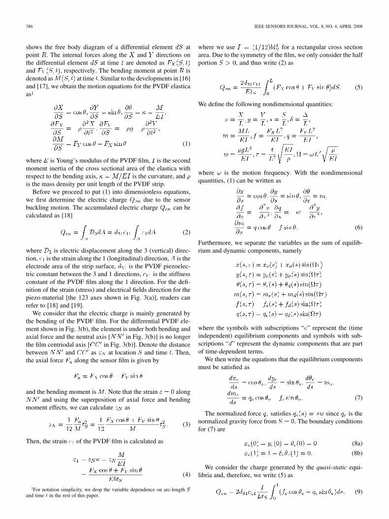
386 IEEE SENSORS JOURNAL, VOL. 8, NO. 4, APRIL 2008
shows the free body diagram of a differential element atpoint . The internal forces along the and directions onthe differential element at time are denoted asand , respectively. The bending moment at point isdenoted as at time . Similar to the developments in [16]and [17], we obtain the motion equations for the PVDF elasticaas1
(1)
where is Young’s modulus of the PVDF film, is the secondmoment inertia of the cross sectional area of the elastica withrespect to the bending axis, is the curvature, andis the mass density per unit length of the PVDF strip.
Before we proceed to put (1) into dimensionless equations,we first determine the electric charge due to the sensorbuckling motion. The accumulated electric charge can becalculated as [18]
(2)
where is electric displacement along the 3 (vertical) direc-tion, is the strain along the 1 (longitudinal) direction, is theelectrode area of the strip surface, is the PVDF piezoelec-tric constant between the 3 and 1 directions, is the stiffnessconstant of the PVDF film along the 1 direction. For the defi-nition of the strain (stress) and electrical fields direction for thepiezo-material [the 123 axes shown in Fig. 3(a)], readers canrefer to [18] and [19].
We consider that the electric charge is mainly generated bythe bending of the PVDF film. For the differential PVDF ele-ment shown in Fig. 3(b), the element is under both bending andaxial force and the neutral axis [ in Fig. 3(b)] is no longerthe film centriodal axis [ in Fig. 3(b)]. Denote the distancebetween and as at location and time . Then,the axial force along the sensor film is given by
and the bending moment is . Note that the strain alongand using the superposition of axial force and bending
moment effects, we can calculate as
(3)
Then, the strain of the PVDF film is calculated as
(4)
1For notation simplicity, we drop the variable dependence on arc-length S
and time t in the rest of this paper.
where we use for a rectangular cross sectionarea. Due to the symmetry of the film, we only consider the halfportion , and thus write (2) as
(5)
We define the following nondimensional quantities:
where is the motion frequency. With the nondimensionalquantities, (1) can be written as
(6)
Furthermore, we separate the variables as the sum of equilib-rium and dynamic components, namely
where the symbols with subscriptions “ ” represent the (timeindependent) equilibrium components and symbols with sub-scriptions “ ” represent the dynamic components that are partof time-dependent terms.
We then write the equations that the equilibrium componentsmust be satisfied as
(7)
The normalized force satisfies since is thenormalized gravity force from . The boundary conditionsfor (7) are
(8a)
(8b)
We consider the charge generated by the quasi-static equi-libria and, therefore, we write (5) as
(9)

YI AND LIANG: A PVDF-BASED DEFORMATION AND MOTION SENSOR: MODELING AND EXPERIMENTS 387
B. Charge Approximation
The exact analytical solutions for the differential (7) with theboundary conditions (8) cannot be obtained [16]. Therefore,we instead approximate the solutions for the boundary-valueproblem given by (7) and (8).
For a small deflection and the fact that the flexuralrigidity is a dominant factor for the PVDF strip, we assume
for a small . We then approximate eachequilibrium component in (7) as a perturbation of terms
Here, we consider the fact that , and are small and,thus, as a sum of odd-power terms of and , and are asa sum of even-power terms of [16].
Substituting the above approximations into (7) and taking thefirst two terms in in each equation, we obtain
(10)
The boundary conditions given by (8) can be rewritten as
(11)
We can solve (10) with the above boundary conditions andobtain solutions for and as
(12a)
(12b)
where constant is determined by the external force . Withand , we can obtain the normalized force from (10) as
and
(13)
For , and , we have
The normalized deflection of the moving end of the PVDFelastica and the maximum height of the PVDF elastica deflec-tion can be calculated as
and
Using (12) and (13), we approximately calculate the electriccharge (9) as
(14)
where in the above approximation, we drop the high-order termsthat contain . Using the relationship , wesimplify (14) as
(15)
where is a constant. It is noted thatthe output charge by the piezoelectric material, such as PVDF,only responses to the dynamic deflection motion . Therefore,the actual output charge should filter out the dc component inthe above approximation given in (15), namely
and if the deflection is small, i.e., , we can further approx-imate the charge as
(16)
Equation (16) implies that the charge generated by the dynamicdeflection is proportional to the deflection magnitude. How-ever, there exists a phase shift between the output chargeand the deflection . We are now ready to discusshow to capture such a nonlinear phase-shift effect.
C. Hysteresis Modeling
The existence of hysteresis between sensor input and outputis widely known for piezoelectric sensors [19]. Fig. 4 show theexperimental results for a buckling test of a PVDF sensor of asize of 32 mm 3 mm 110 m under a sinusoidal deflection
mm. Fig. 4(a) shows the time-tra-jectory and Fig. 4(b) shows a hysteresis curve between charge
and deflection due to their phase differences.We consider a Duhem model to capture the rate-independent
hysteresis relationship between the charge outputs and[20], [21]. Here, we consider the buckling-generated chargeas the input to the hysteresis operator, namely, .

388 IEEE SENSORS JOURNAL, VOL. 8, NO. 4, APRIL 2008
Fig. 4. (a) Measured charge output and the cyclic deflection �(t) = 4[�1 +sin(10�t)] mm. (b) A hysteresis curve between the charge Q and deflection�.
The Duhem model represents operator by a first-ordernonlinear differential equation as
(17)
where and are model constants thatdepend on the shape and area of the experimental hysteresiscurves. In (17), the output charge is considered as the statevariable of the differential equation and is dependent on thevalues of both and . Such a mathematical relationship(17) can reproduce the hysteresis phenomena that we observe inexperiments. Readers can refer to [21] for more details on howto estimate these hysteresis model parameters.
It is noted that due to the existing hysteresis in PVDF piezo-electric materials, the output charge is a nonlinear functionof the deflection although the calculated charge dueto the buckling motion is linear in , as shown in (16). Inthe next section, we will discuss experiments and estimation ofmodel parameters for sensor output charge models.
Fig. 5. (a) A experiment setup for buckling sensor testing. (b) A buckled PVDFsensor.
III. EXPERIMENTS
A. Experiment Setup
We have developed a deformation sensor characteristictesting kit to experimentally capture and validate the relation-ship between the sensor output charge and the deflection. Fig. 5shows the experiment setup. We use several types of metalizedPVDF thin films (from Measurement Specialties, Inc.) withdifferent thicknesses. The PVDF thin-film is fabricated intodifferent sizes. Thin wires are connected to one end of thesensor by conductive glue. A computer-controlled linear stage(Parker MX80S) is used to move one end of the PVDF sensorfilm to simulate the deflection motion, while the other end ofthe sensor is clamped at a stationary fixture. A laser deflectionsensor (Banner LG5) is employed to monitor the deflectionof the PVDF thin-film sensor at a fixed location. The linearstage controller is implemented using a high-performanceservo control board (NI PCI 7350) from National Instruments,Inc. The controlled motion trajectory is designed through NILabView. A data acquisition system (NI PCI 6221) records

YI AND LIANG: A PVDF-BASED DEFORMATION AND MOTION SENSOR: MODELING AND EXPERIMENTS 389
Fig. 6. (a) The output charge of a PVDF sensor under a sinusoidal deflectionmotion with frequencies of 5 and 10 Hz and a peak amplitude of 8 mm for aPVDF sensor of a size of 32 mm� 3 mm� 110 �m. (b) Output charge peakvalues Q versus excitation frequency f under a sinusoidal deflection motionwith a peak amplitude of 2 mm for a PVDF sensor of a size of 10 mm� 1mm� 28 �m.
sensor output and feedback motion information. The sensoroutput is conditioned by a charge amplifier (PCB 422E03)before the data is sampled through the data acquisition system.
B. Experiment Results
In all experiments, we choose that the peak-to-peak amplitudeof the sinusoidal deflection is around 50% of the sensorlength . We first test the PVDF sensor under buckling withvarious motion frequencies. Fig. 6(a) shows the output charge
as a function of the deflection under a sinusoidal mo-tion of two frequencies. The PVDF sensor is of a size of 32mm 3 mm 110 m and the peak amplitude of the deflectionis 8 mm (peak-to-peak amplitude is 16 mm). From Fig. 6(a),it is clearly observed a fixed hysteresis pattern under both fre-quencies. We also take a smaller size PVDF sensor (10 mm 1mm 28 m) and measure the sensor output under a sinusoidal
Fig. 7. Output charge peak values Q versus deflection peak ampli-tudes under a 2 Hz sinusoidal motion for a PVDF sensor of a size of10 mm� 1 mm� 28�m.
Fig. 8. Measured and estimated hysteresis curves for a PVDF sensor of a sizeof 25 mm� 3 mm� 110 �m under a 5 Hz and 6 mm peak amplitude sinusoidaldeflection motion.
deflection of a peak amplitude of 2 mm (peak-to-peak amplitudeis 4 mm) with various frequencies. Fig. 6(b) illustrates that thepeak charge values are kept constantly under a varying excita-tion frequency from 1 to 10 Hz. These results confirm that thehysteresis generated by PVDF thin-film is independent of thetime scale of the input excitation and thus rate-independent.
Fig. 7 shows that the peak values of the sensor output chargeare proportional to the deflection peak amplitude. Such an ob-servation validates our analysis of the output charge as given by(16). Note that the linear correlation between the magnitudes ofoutput charge and deflection only shows their peakvalue relationship. Due to the existing hysteresis, the instanta-neous relationship between and is highly nonlinearand in the following we are going to estimate the hysteresismodel.
Fig. 8 shows a comparison between the measured and Duhemmodel-based estimated hysteresis curves between and

390 IEEE SENSORS JOURNAL, VOL. 8, NO. 4, APRIL 2008
TABLE IESTIMATED PARAMETERS OF THE DUHEM HYSTERESIS MODEL
AND SENSOR MODEL
Fig. 9. (a) Measured and model estimated charge values Q (t) for a PVDFsensor of a size of 25 mm� 3 mm� 110 �m under a sinusoidal deflection mo-tion at a frequency of 5 Hz and with a peak amplitude of 6 mm. (b) Model-basedestimated charge versus measurement.
. The PVDF sensor in the estimation is of a size of25 mm 3 mm 110 m and the deflection is in a sinusoidalform with a frequency of 5 Hz and a peak amplitude of 6 mm(a peak-to-peak amplitude is 12 mm). The Duhem hysteresismodel parameters are listed in Table I. Those parameters areobtained from the experiments by the relationships given in[21]. The estimated hysteresis curve fits well with the measure-ments. Note that at the positive peak values in the experimentalmeasurement, the sensor has been pulled slightly by the linear
stage and, thus, we observe a “sharp” peak in each cycle. It isalso noted that in Fig. 8 the first few cycles in the estimatedcurves are in transient and not consistent with steady-statecurves due to the use of a zero initial condition in the Duhemmodel.
Fig. 9 shows the comparison of model-based estimates ofthe output charge with the measurements. It is again shown inFig. 9(a) that there is a sharp peak at the positive cycle due tothe pull effect of the linear stage in experiments. A comparisonplot of the estimated versus measured charge values shown inFig. 9(b) demonstrates a linear relationship with a slope of valueof one. These results validate that the hysteresis model-based es-timation captures the sensor measurements within a small errorrange.
IV. CONCLUSION
The use of the PVDF-based buckling sensor for deformationand motion measurements discussed in this paper is motivatedby the applications of tire rubber deformation and insect loco-motion studies. By sensing mechanism design in these appli-cations, the PVDF sensors are under a cyclic buckling motion,and only two ends are attached to sensed object. In this paper,we presented the mathematical modeling, analysis, and exper-imental validation for such PVDF sensors. The modeling ap-proach was taken into two steps: we first treated PVDF thin-filmas a heavy elastica strip and a sensor model was developed. Wefound that for a small deflection, the magnitude of the sensoroutput charge is proportional to the deflection magnitude. How-ever, there is a phase shift between the charge and motion de-flection and a hysteresis pattern has been observed. A Duhemhysteresis model was then used to capture such a nonlinear re-lationship between the charge and the deflection. The integratedmodel of the elastica buckling and hysteresis analysis was esti-mated and validated by experiments on a computer-controlledlinear motion-stage testbed.
We plan to extend the current research into several directions.We like to integrate a dynamic hysteresis inverter to compensatethe nonlinear hysteresis effect and, thus, build a linear relation-ship between the arbitrary input deflection and sensor measure-ments. We also plan to refine our modeling development andapply the refined sensing models for the two applications men-tioned in this paper. We will report these developments in thefuture.
ACKNOWLEDGMENT
The authors thank B. Mika for setting up the experimentalapparatus and collecting all test data. They are also grateful toProf. D. Song, Prof. R. Langari, and Prof. S. Khatri at TexasA&M University for helpful discussions.
REFERENCES
[1] B. Li and V. Giurgiutiu, “Modeling and testing of pzt and PVDFpiezoelectric wafer active sensors,” Smart Mat. Struct., vol. 15, pp.1085–1093, 2006.
[2] M. Toda and M. Thompson, “Contact-type vibration sensors usingcurved clamped PVDF film,” IEEE Sensors J., vol. 6, no. 5, pp.1170–1177, 2006.
[3] R. Marsili, “Measurement of the dynamic normal pressure betweentire and ground using PVDF piezoelectric films,” IEEE Trans. Instrum.Meas., vol. 49, no. 4, pp. 736–740, Aug. 2000.
YI AND LIANG: A PVDF-BASED DEFORMATION AND MOTION SENSOR: MODELING AND EXPERIMENTS 391
[4] S. K. Kim, I. Cho, J. H. Lee, J. Park, D. H. Yi, and D. Cho, “A newmethod for accurately estimating the weight of moving vehicles usingpiezoelectric sensors and adaptive-footprint tire model,” Veh. Syst.Dyn., vol. 39, no. 2, pp. 135–148, 2003.
[5] “Federal motor vehicle safety standard: Tire pressure monitoring sys-tems; controls and displays,” National Highway Traffic Safety Admin-istration, Dept. Transportation, 2000, docket No. NHTSA 2000–8572.
[6] J. Yi, “A piezo-sensor based ‘smart tire’ system for mobile robots andvehicles,” IEEE/ASM Trans. Mechatron., vol. 13, no. 1, pp. 95–103,2008.
[7] APOLLO Consortium, “Intelligent tyre systems - state of the art andpotential technologies,” Technical Research Centre of Finland (VTT),APOLLO Deliverable D7 for Project IST-2001–34372, 2003.
[8] O. Yilmazoglu, M. Brandt, J. Sigmund, E. Genc, and H. Hartnagel, “In-tegrated inas/gasb 3D magnetic field sensors for ‘the intelligent tire’,”Sens. Actuators, A, vol. 94, pp. 59–63, 2001.
[9] A. Pohl, R. Steindl, and L. Reindl, “The ‘intelligent tire’ utilizing pas-sive saw sensors—measurement of tire friction,” IEEE Trans. Instrum.Meas., vol. 48, no. 6, pp. 1041–1046, Aug. 1999.
[10] R. Matsuzaki and A. Todoroki, “Wireless flexible capacitive sensorbased on ultra-flexible epoxy resin for strain measurement of automo-bile tires,” Sens. Actuators, A, vol. 140, pp. 32–42, 2007.
[11] K. Moon, H. Liang, J. Yi, and B. Mika, “Tire tread deformation sensorand energy harvester development for ‘Smart Tire’ applications,” inProc. SPIE, San Diego, CA, 2007, vol. 6529.
[12] J. Yi and H. H. Liang, “Development of a PVDF-based tire tread de-formation sensing system,” in Proc. 2007 World Forum on Smart Mat.Smart Struct. Tech., Nanjing, China, 2007.
[13] H. Lee, R. Cooper, B. Mika, D. Clayton, R. Garg, J. Gonzales, S.Vinson, S. Khatri, and H. Liang, “Polymeric sensors to monitor cock-roach locomotion,” IEEE Sensors J., vol. 7, no. 12, pp. 1698–1702,Dec. 2007.
[14] I. Chopra, “Review of state of art of smart structures and integratedsystems,” AIAA J., vol. 40, no. 11, pp. 2145–2187, 2002.
[15] R. G. Ballas, H. Schlaak, and A. Schmid, “The constituent equationsof piezoelectric multilayer bending actuators in closed analytical formand experimental results,” Sens. Actuators, A, vol. 130–131, pp. 91–98,2006.
[16] C. Wang, “On symmetric buckling of a finite flat-lying heavy sheet,”ASME J. Appl. Mech., vol. 51, no. 2, pp. 278–282, 1984.
[17] S. Santillan, L. Virgin, and R. Plaut, “Post-buckling and vibration ofheavy beam on horizontal or inclined rigid foundation,” ASME J. Appl.Mech., vol. 73, no. 4, pp. 664–671, 2006.
[18] IEEE Standard on Piezoelectricity, ANSI/IEEE Std. 176–1987, 1987.[19] V. Giurgiutiu and S. Lyshevski, Micromechatronics: Modeling, Anal-
ysis, and Design with MATLAB.. Boca Raton, FL: CRC Press, 2004.
[20] B. Coleman and M. Hodgdon, “A constitutive relation for rate-inde-pendent hysteresis in ferromagnetically soft materials,” Int. J. Eng. Sci.,vol. 24, no. 6, pp. 897–919, 1986.
[21] H. Adriaens, W. de Koning, and R. Banning, “Modeling piezoelectricactuators,” IEEE/ASME Trans. Mechatron., vol. 5, no. 4, pp. 331–341,Dec. 2000.
Jingang Yi (S’99–M’02–SM’07) received the B.S.degree in electrical engineering from the ZhejiangUniversity, Hangzhou, China, in 1993, the M.Eng.degree in precision instruments from TsinghuaUniversity, Beijing, China, in 1996, the M.A. degreein mathematics, and the Ph.D. degree in mechanicalengineering from the University of California,Berkeley, in 2001 and 2002, respectively.
He is currently an Assistant Professor of Mechan-ical Engineering at San Diego State University, SanDiego, CA. From May 2002 to January 2005, he was
with Lam Research Corporation, Fremont, CA, as a member of Technical Staff.From January 2005 to December 2006, he was with the Department of Mechan-ical Engineering, Texas A&M University, as a Visiting Assistant Professor. Hisresearch interests include autonomous and robotic systems, dynamic systemsand control, intelligent sensing and actuation systems, mechatronics, automa-tion science and engineering, with applications to semiconductor manufacturingand intelligent transportation systems.
Dr. Yi is a member of the American Society of Mechanical Engineers(ASME). He was the recipient of the Kayamori Best Paper Award of the 2005IEEE International Conference on Robotics and Automation (ICRA) and theBest Conference Paper Finalist of the 2007 IEEE International Conference onAutomation Science and Engineering (CASE).
Hong Liang received the Ph.D. degree in mate-rials science from Stevens Institute of Technology,Hoboken, NJ.
She is an Associate Professor and Jordan CareerDevelopment Professor with the Department ofMechanical Engineering, Texas A&M University,College Station. She has more than 120 technicalpublications including three books. Her research areaincludes sensor design and materials development,as well as characterization.
Prof. Liang is the recipient of the NSF CAREERAward. She is a Fellow of the Society of Tribologists and Lubrication Engineers.