39g from thailand.pdf
DESCRIPTION
AHUTRANSCRIPT

Air Handling UnitsNominal: 900-43,000 CFM
39G Series
www.carrier.co.thWorld's No.1 Air Conditioning Expert

Table of contents
Introduction ...................................................................................................................................................... 3
Identification .................................................................................................................................................... 4
Quick Selection Chart .................................................................................................................................... 5
Unit Configuration ...................................................................................................................................... 6-7
Casing .............................................................................................................................................................. 8-9
A. General
B. Frames
C. Panels
D. Insulation
E. Base Unit Casing Weight
Fan ............................................................................................................................................................... 10-18
A. General
B. Description
C. Recommendations
D. Fan Length
E. Fan Discharge Outlet Dimension
F. Fan Shaft Diameter
G. Fan Housing Dimension & Weight
H. Fan Motor Weight
I. Fan Size and RPM Limitation/BkW Limitation
Coils ............................................................................................................................................................. 19-25
A. General
B. Chilled Water Coils
C. Hot Water Coil
D. Direct Expansion Coil
E. Condensate Drain Pan
F. Coil Weight
G. Connection Outline
Mixing Box ...................................................................................................................................................... 26
A. General
Filter ............................................................................................................................................................ 27-28
A. General
B. High Velocity Filter
C. Bag Filter
D. Friction Pressure Drop

39G Series
Introduction
Note: ZINCALUME® and COLORBOND® are registered trade marks of BHP Steel (JLA) Pty. Ltd.
FLEXIBILITY IN PANEL CONSTRUCTION
Units are offered with double wall construction sheet metal
with 26 Gauge Colorbond® XMA (ABR) as Outer casing
and 26 Gauge Galvanized Steel as Inner Casing for 25mm.
VIBRATION ISOLATION
Centrifugal fan motor packages are mounted on common
bases with 1" deflection spring or 0.5" deflection rubber as
standard vibration isolators and flexible discharge connec-
tions ensuring that all moving parts are independently
isolated from the casing structure.
AESTHETICS
The standard construction features external panels surface
attractively finished with Colorbond® XMA (ABR) and the
units are delivered with heat-shrink plastic covering which
keep the panels in good condition.
ACCESSIBILITY AND MAINTENANCE
The easily removable panels and quick release access
doors offer complete accessibility to fans, coils, filters and
dampers. Additional access sections can be provided
between coils and filters if required.
All basic component parts are standard and interchange-
able. Filters are commercially available standard items
conforming to international standards and sizes.
INDIVIDUALISED PRODUCT LINE
All 22 model sizes are available as 'Customised' adapted
exactly to meet specific job requirements. For example:
Non-standard coil material, CCN, ANC, attenuators, etc.....
The purpose of this catalogue is to help consulting engineers in the preliminary
selection of CARRIER AIR HANDLING UNITS. However, if required, your local
CARRIER office will assist to provide a computerised selection to confirm or
complete your preliminary selection.
This catalogue consists of:
• A description of the various component parts available to be combined
in the order best suited to your requirements.
• Technical data sheets, dimensions, weights, specifications, charts, etc.
QUALITY
The quality and reliability of any system depends on the
quality of the components parts. Equipment schedules and
specifications are based on Carrier 39G GALAXY.
Therefore, in line with other CARRIER products, our 39G
Series Air Handlers are manufactured in conformity with
CARRIER’s Quality concept which brought in items
subjected to rigorous inspection.
FLEXIBLE MODULAR CONSTRUCTION
This adaptable unit design which is based upon a wide
range of standard panel sizes, frequently enables
CARRIER to offer several configurations of unit height and
width, so that the aesthetic or practical dictates of confined
plant room space or rooftop silhouettes can be easily met.
Major items of unit such as fans, coils, filters, etc. can be
arranged in the sequence dictated by the job requirements,
and separated by access sections where necessary, giving
complete flexibility of design.
RIGIDITY
Extruded aluminium internal posts within the extruded
aluminium frame increase the structural rigidity and provide
a fixing point for an air-tight sealing strip.
The panels shall be constructed such that they shall be of
two layers of steel sheet with injected insitu CFC-Free
Polyurethane insulation with thermal conductivity factor of
0.019 W/mK and density of 40kg/m3 in between to ensure
effective thermal and acoustic insulation.
WIDE RANGE OF SIZES
There are 22 standard units sizes available, each, in most
cases, has a choice of 2 fan type, covering 22 CFM breaks
ranging from 900 to 43,000 Nominal CFM.
3

4
39G Identification & dimension
4 modules
1 module
5 modules
Width
1 module
Left Hand Right Hand
Air flow
Height
Length
Dependent on number
and size of component
parts
Remark: Must add base frame (100 mm.) to external height dimension to get the overall height of unit.
A. General
The 39G line of Carrier Air Handling Unit is based on a MODULAR System.
The number of modules in height and in width determine the cross-section available for air flow and encodes the unit size.
The unit length is determined by the number and size of the component parts required.
The side for service (connections and access) is defined as right hand or left hand in the direction of air flow.
Each module has a constant value of 100mm. To determine external dimensions, the following formula applies:
External Dimensions = (n x 100 + m) mm
where n = number of module
m = 110mm for 25mm casing
Example 2: 39G0713 for 25mm casing
External Height Dimension = 07 x 100 + 110 = 810mm
External Width Dimension = 13 x 100 + 110 = 1410mm
B. Shipping Dimension
To estimate the skid/closed crate dimensions of a complete module section or unit for shipment purpose.
1. Section (or Unit) without MXB: ADD
i. 400mm (skid only or inclusive crate) to its module width.
ii. 200mm (skid only) or 277mm (inclusive crate) to its module length.
iii. 100mm (skid only) or 278mm (inclusive crate) to its module height.

5
Qu
ick
se
lec
tio
n c
ha
rt
02
46
810
12
14
16
18
20
22
24
26
28
30
32
34
36
38
05
08
A
05
08
B
05
11
06
12
07
13
08
13
09
14
09
16
10
18
111
8
13
19
14
22
15
22
17
22
17
24
17
25
19
26
21
27
22
30
22
34
24
34
26
36
0.1
7
0.2
5
0.3
4
0.4
9
0.7
0
0.8
1
1.0
5
1.1
5
1.4
4
1.6
8
2.0
8
2.3
6
2.5
5
2.9
3
3.3
0
3.5
9
3.9
6
4.6
3
5.4
8
6.4
2
6.9
9
8.1
2
0.0
70
.31
40
.62
10
.92
81
.23
51
.54
21
.74
92
.05
62
.36
32
.67
03
.0
0.30.40.6
1.1
0.5
0.9
1.5
0.7
1.2
2.2
1.1
1.8
3.2
1.2
2.0
3.6
1.6
2.6
4.7
1.7
2.9
5.2
2.2
3.6
6.5
2.5
4.2
7.6
3.1
5.2
9.4
3.5
5.9
10.6
3.8
6.4
11.5
4.4
7.3
13.2
5.0
8.3
14.9
5.4
9.0
16.2
5.9
9.9
17.8
6.9
11.6
20.8
8.2
13.7
24.7
9.6
16.1
28.9
10.5
17.5
31.5
12.2
20.3
36.5
0.40.8
1.5
m/s
MIN
. C
OIL
FA
CE
VE
LO
CIT
Y,
CO
OL
ING
OR
HE
AT
ING
2.5
m/s
MA
X.
CO
IL F
AC
E V
EL
OC
ITY,
CO
OL
ING
WIT
HO
UT
EL
IMIN
AT
OR
4.5
m/s
MA
X.
CO
IL F
AC
E V
EL
OC
ITY,
HE
AT
ING
1.5
2.5
4.5
AIR
VO
LU
ME
, 1
/s x
10
00
CA
PA
CIT
Y, K
W
CARRIER 39G UNIT SIZE
COIL FACE AREA (sq.m)
No
te:
For
Chi
lled
Wat
er a
pplic
atio
n be
twee
n 2.
5 &
3.1
5 m
/sec
. fac
e ve
loci
ty, t
he u
se o
f Drif
t Elim
inat
or is
nec
cess
ary.

6
Table 1 Unit Configuration (Horizontal Application) STD 2/2A
0508A
FC - 160 1~1.5 555 1110 710 910 1 100
FC - 180 1.5~2 0508B FC - 180 1.5~2 555 1110 710 910 1 100 0511 FC - 200 1.5~3 655 1210 710 1210 1 100
0612 FC - 225 2~4
655 1210 810 1310 1 100 BC - 225 3~5
0713 FC - 280 3~5
755 1310 910 1410 1 100 BC - 280 4~7.5
0813 FC - 315 4~5
855 1410 1010 1410 1 100 BC - 315 5~7.5
0914 FC - 355 4~7.5
955 1510 1110 1510 1 100 BC - 355 5~10
0916 FC - 355 4~7.5
955 1510 1110 1710 1 100 BC - 355 7.5~15 FC - 400 5~10
1018 FC - 450 7.5~10
1055 1610 1210 1910 1 100 BC - 400 7.5~15 BC - 450 10~15
1118 FC - 450 7.5~15
1055 1610 1310 1910 1 100 BC - 450 10~15 FC - 450 7.5~15
1055 1610
1319 BC - 450 10~15
1510 2010 1 100 FC - 500 10~20
1155 1710 BC - 500 15~20 FC - 500 10~15
1155 1710
1422 BC - 500 10~15
1610 2310 1 100 FC - 560 15~20
1255 1810 BC - 560 15~20 FC - 560 15~20
1310 1920
1522 BC - 560 15~20
1710 2310 2 100 FC - 630 15~25
1510 2120 BC - 630 20~25 FC - 630 15~20
1510 2120
1722 BC - 630 15~25
1910 2310 2 100 FC - 710 20~25
1610 2220 BC - 710 20~30 FC - 630 15~25
1510 2120
1724 BC - 630 15~25
1910 2510 2 100 FC - 710 20~30
1610 2220 BC - 710 20~30 FC - 630 15~25
1510 2120
1725 BC - 630 15~25
1910 2610 2 100 FC - 710 20~30
1610 2220 BC - 710 25~40 FC - 710 15~25
1610 2220
1926 BC - 710 20~30
2110 2710 2 100 FC - 800 25~40
1810 2420 BC - 800 25~40 FC - 710 15~25
1610 2220
2127 BC - 710 20~30
2310 2810 2 100 FC - 800 25~40
1810 2420 BC - 800 30~50 FC - 800 20~30
1810 2420
2230 BC - 800 20~30
2410 3110 2 100 FC - 900 30~50
2010 2620 BC - 900 40~50 FC - 800 20~40
1810 2420
2234 BC - 800 20~40
2410 3510 2 100 FC - 900 30~60
2010 2620 BC - 900 40~60 FC - 900 25~40
2010 2620
2434 BC - 900 25~40
2610 3510 2 100 FC - 1000 40~60
2110 2720 BC - 1000 40~60 FC - 900 25~50
2010 2620
2636 BC - 900 25~50
2810 3710 2 100 FC - 1000 40~75
2110 2720 BC - 1000 40~75
Unit Size Fan SizeRange of Motor HP
Unit Length (mm)
A
25 mm
B
25 mm
Unit Height (mm)
25 mm
Unit Width (mm) No. of Section
Shipped
Add on HYF Filter Track
(mm)25 mm
A
B
Add on HVF Filter Track
Figure 1
Remark : Unit height included base frame (100 mm.)
Unit configuration
7
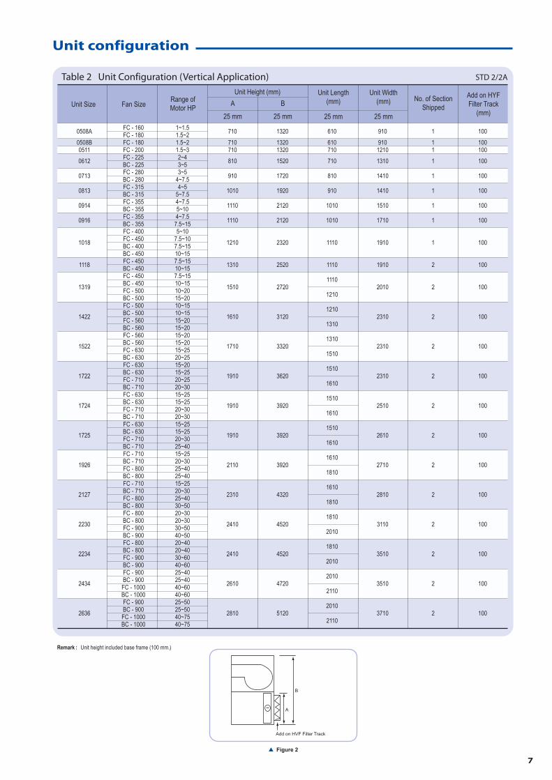
Unit configuration
Table 2 Unit Configuration (Vertical Application) STD 2/2A
0508A
FC - 160 1~1.5 710 1320 610 910 1 100
FC - 180 1.5~2 0508B FC - 180 1.5~2 710 1320 610 910 1 100 0511 FC - 200 1.5~3 710 1320 710 1210 1 100
0612 FC - 225 2~4
810 1520 710 1310 1 100 BC - 225 3~5
0713 FC - 280 3~5
910 1720 810 1410 1 100 BC - 280 4~7.5
0813 FC - 315 4~5
1010 1920 910 1410 1 100 BC - 315 5~7.5
0914 FC - 355 4~7.5
1110 2120 1010 1510 1 100 BC - 355 5~10
0916 FC - 355 4~7.5
1110 2120 1010 1710 1 100 BC - 355 7.5~15 FC - 400 5~10
1018 FC - 450 7.5~10
1210 2320 1110 1910 1 100 BC - 400 7.5~15 BC - 450 10~15
1118 FC - 450 7.5~15
1310 2520 1110 1910 2 100 BC - 450 10~15 FC - 450 7.5~15
1110
1319 BC - 450 10~15
1510 2720
2010 2 100 FC - 500 10~20
1210 BC - 500 15~20 FC - 500 10~15
1210
1422 BC - 500 10~15
1610 3120
2310 2 100 FC - 560 15~20
1310 BC - 560 15~20 FC - 560 15~20
1310
1522 BC - 560 15~20
1710 3320
2310 2 100 FC - 630 15~25
1510 BC - 630 20~25 FC - 630 15~20
1510
1722 BC - 630 15~25
1910 3620
2310 2 100 FC - 710 20~25
1610 BC - 710 20~30 FC - 630 15~25
1510
1724 BC - 630 15~25
1910 3920
2510 2 100 FC - 710 20~30
1610 BC - 710 20~30 FC - 630 15~25
1510
1725 BC - 630 15~25
1910 3920
2610 2 100 FC - 710 20~30
1610 BC - 710 25~40 FC - 710 15~25
1610
1926 BC - 710 20~30
2110 3920
2710 2 100 FC - 800 25~40
1810 BC - 800 25~40 FC - 710 15~25
1610
2127 BC - 710 20~30
2310 4320
2810 2 100 FC - 800 25~40
1810 BC - 800 30~50 FC - 800 20~30
1810
2230 BC - 800 20~30
2410 4520
3110 2 100 FC - 900 30~50
2010 BC - 900 40~50 FC - 800 20~40
1810
2234 BC - 800 20~40
2410 4520
3510 2 100 FC - 900 30~60
2010 BC - 900 40~60 FC - 900 25~40
2010
2434 BC - 900 25~40
2610 4720
3510 2 100 FC - 1000 40~60
2110 BC - 1000 40~60 FC - 900 25~50
2010
2636 BC - 900 25~50
2810 5120
3710 2 100 FC - 1000 40~75
2110 BC - 1000 40~75
Unit Size Fan SizeRange of Motor HP
Unit Height (mm)
A
25 mm
B
25 mm
Unit Length (mm)
25 mm
Unit Width (mm) No. of Section
Shipped
Add on HYF Filter Track
(mm)25 mm
Figure 2
Add on HVF Filter Track
A
B
Remark : Unit height included base frame (100 mm.)

8
Casing
SEE DETAIL A
6
3
2
4
SEE DETAIL ASCALE 3.10
7
1
5
1. Extruded Aluminium Frame2. Polystyrene3. Trileg4. Panel5. Rivet6. PU Insulation7. Rib Seal
Figure 3 Cross Section of Panels, Rib-Seal and Others
A. General
The casing of 39G units is formed by:
• extruded aluminium perimeter frame, inner post and
intermediate post.
• removable and fixed panels
• internal insulation
All external panels are Colorbond® XMA (ABR) steel.
B. Frames
The frame is made up of 4 components (Figure 3)
1. Extruded aluminium frame
2. Composite corner piece
3. Extruded Internal post
4. Extruded Intermediate post
1. Extruded Aluminium Frame
Forms the overall shape of the section and receives the
panels. The extruded aluminium frame is manufactured
from extrusion process using aluminium (Grade 6063 - T5)
with mill finish 1.5mm thickness.
2. Composite Material Corner Piece (Trilegs)
The composite corner piece is composed of Nylon 66 +
33% GF (25mm casing) and Nylon 6 + 30% GF (50mm
casing) with fine finish surface and it is grey in color
confirming to RAL 7042.
3. Extruded Inner Post
Extruded aluminium inner post within the extruded alu-
minium frame increase the structural rigidity and provide a
fixing point for an air-tight sealing strip.
2. Removable / Access Panel
Are constructed of the same material as the fixed panels.
The access panel shall be low leak construction with a hex
socket compression type latch assembly and large & non-
conductive handles for easy removal of the access panel.
(Figure 5 for Cross Section of Latch Assy.)
The removable / access panel shall be double skinned
construction and internally insulated with injected insitu
CFC-Free Polyurethane insulation. The access panel
mating surface perimeter shall be lined with Rib-Seals.
Optional : Wrap-around gasket (Figure 4) to replace rob-
seal for enhancement of insulation on the
aluminium frames to prevent condensation start
on aluminium frames which should be suitable to
units with ducted return application. It has shown
that with wrap-around gasket on frames, it will on
condensation at high humidity ambient.
C. Panels
1. Fixed Panels
Forms the insulated enclosure of the casing and giving it
rigidity and air-tightness, they consist of:
• external sheet metal
• insulation
• internal protective cover
The Colorbond® XMA (ABR) steel sheet with 26 Gauge
thickness and the galvanized steel inner casing (26 Gauge)
form double wall construction with PU insulation between
the inner and the outer panel. Rivets are used to affix panel
to AHU framework.
Figure 4 Cross Section of Panel and Framework
External Panel
Internal Panel
Rubber Gasket
PU InsulationExtruded Aluminium Frame

9
2
3
41
5
6
Figure 5 Cross Section of Latch Assy
Explanation1. Panel2. Screw, Socket Head Cap (PREMACHINE)3. Powl4. Spacer5. Nut, Hex HD M8 (Nylon Lock)6. Washer
Casing
Note : Weight in kg
MXB Fan Coil HVF BF LVF ACC
25 mm 25 mm 25 mm 25 mm 25 mm 25 mm 25 mm
0508A 51 25 25 10 34 35 30
0508B 51 25 25 10 34 35 30
0511 66 30 30 12 42 42 36
0612 70 40 33 13 46 54 40
0713 82 50 35 14 50 62 42
0813 94 60 37 15 54 64 44
0914 100 72 40 16 60 73 48
0916 110 78 43 17 65 78 52
1018 118 95 48 19 73 94 58
1118 120 100 50 20 75 98 60
1319 122 115 52 21 78 108 62
1422 131 151 56 22 82 117 65
1522 140 169 58 25 85 123 67
1722 147 183 60 27 91 139 71
1724 155 189 63 29 96 147 75
1725 167 201 66 31 100 159 77
1926 172 224 68 33 107 168 82
2127 185 260 72 35 114 180 87
2230 195 308 76 37 119 208 90
2234 215 342 80 39 126 222 95
2434 225 363 84 41 131 230 98
2636 240 419 89 43 139 245 104
Unit Size
Table 3 Base Unit Casing Weight
E. Base Unit Casing Weight
Table below shows the base unit casing weight (approximation) for 25mm casing.
3. COLORBOND® XMA (ABR) prepainted steel
Panels made from BHP COLORBOND® XMA (ABR) steel
provide excellent corrosion resistance and are suitable for
outdoor durability. The substrate, ZINCALUME® zinc/
aluminium alloy-coated steel complies with AS1397-1993
and the paint coating complies with AS/NZS 2728-1997.
Below are the specifications of COLORBOND® XMA (ABR)
steel.
Pretreatment - Corrosion resistant proprietary
conversion coating.
Primer Coat - Universal corrosion inhibitive primer.
Nominal thickness 5µm top side.
Finish Coat - Custom formulated system. Nominal
thickness 20µm top side in white color.
D. Insulation
The panels are frames and thermally insulated. The panels
shall be constructed such that they shall comprise of two
layers of steel sheet with injected insitu CFC-Free polyure-
thane insulation with thermal conductivity factor of 0.019 w/
mK and density of 40 kg/m3 in between.

10
Fan
PW2 = PW1
y2
y1
P2 = P1
n2
n1
( )2
PW2 = PW1
n2
n1
( )3
P2 = P1
y2
y1
and
V2 = V1
n2
n1
B. Description
1. Type of Fans
39G air handling units are supplied with double inlet,
double width (DIDW) centrifugal blowers of either:
i) Forward curved (FC)
ii) Backward curved (BC)
2. Construction
a) Fan casings are constructed of galvanized steel with a
series of punched holes or nutserts allowing the fixing
of accessories such as frames or support legs thus
providing a variety of discharge positions.
b) The impeller is galvanized finished for forward curved
fan and epoxy painted for backward curved and
securely fixed to the shaft. (bored & keywayed)
Backward curved fan has lower energy consumption
due to its high performance impeller with welded true
aerofoil blades inclined obliquely to the shaft axis. All
fan impellers are statically and dynamically balanced
to the operating fan speed as shown in the equipment
schedule in accordance with ISO 1940 Part 1. Quality
level G2.5.
c) Shafts are trued in accordance with DIN 748. Toleranz
class g6
d) Deep groove ball bearings are supplied for smaller fan
size. Self aligning Single row ball bearings mounted
with a cast iron housing (real plummer block bearing)
for size 400-1000. All bearings are pre-lubricated from
the factory. Higher life expectancy bearings are
available as option.
C. Recommendations
The air to be handled in the unit must be clean, and non-
corrosive.
Each air handling unit can have a choice of several fan
type with best efficiency and lowest sound level should be
selected for a specific installation.
A. General
1. Fan Laws
For a given distribution system and specific air weight, the
following laws in relation to volume, pressure and fan
power applied dependent upon fan speed.
• The volume (V) changes as the fan speed (n) changes
• The pressure (p) changes with the square of the speed
(n)
• The absorbed power (Pw) changes with the cube of the
speed (n)
• As the specific weight of the air changes, the air
quantities remain constant.
• The pressure and the absorbed power change with the
specific weight.
2. Reference Values
The fan curves refer to a specific weight of 1.2 kgf/m3 at a
temperature of 20˚C at atmospheric pressure of 101.3 kPa
(760mm Hg) and a relative humidity of 50%.
11
Fan
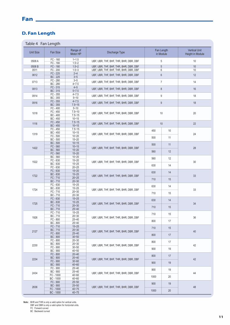
Table 4 Fan Length
0508 A
FC - 160 1~1.5 UBF, UBR, THF, BHF, THR, BHR, DBR, DBF 5 10
FC - 180 1.5~2
0508 B FC - 180 1.5~2 UBF, UBR, THF, BHF, THR, BHR, DBR, DBF 5 10
0511 FC - 200 1.5~3 UBF, UBR, THF, BHF, THR, BHR, DBR, DBF 6 10
0612
FC - 225 2~4 UBF, UBR, THF, BHF, THR, BHR, DBR, DBF 6 12
BC - 225 3~5
0713
FC - 280 3~5 UBF, UBR, THF, BHF, THR, BHR, DBR, DBF 7 14
BC - 280 4~7.5
0813
FC - 315 4~5 UBF, UBR, THF, BHF, THR, BHR, DBR, DBF 8 16
BC - 315 5~7.5
0914
FC - 355 4~7.5 UBF, UBR, THF, BHF, THR, BHR, DBR, DBF 9 18
BC - 355 5~10
0916
FC - 355 4~7.5 UBF, UBR, THF, BHF, THR, BHR, DBR, DBF 9 18
BC - 355 7.5~15
FC - 400 5~10
1018
FC - 450 7.5~10 UBF, UBR, THF, BHF, THR, BHR, DBR, DBF 10 20
BC - 400 7.5~15
BC - 450 10~15
1118
FC - 450 7.5~15 UBF, UBR, THF, BHF, THR, BHR, DBR, DBF 10 22
BC - 450 10~15
FC - 450 7.5~15 450 10
1319
BC - 450 10~15 UBF, UBR, THF, BHF, THR, BHR, DBR, DBF 24
FC - 500 10~20 500 11
BC - 500 15~20
BC - 500 10~15 500 11
1422
FC - 560 10~15 UBF, UBR, THF, BHF, THR, BHR, DBR, DBF 28
BC - 560 15~20 560 12
FC - 560 15~20
BC - 560 10~20 560 12
1522
FC - 630 15~20 UBF, UBR, THF, BHF, THR, BHR, DBR, DBF 30
BC - 630 15~25 630 14
FC - 630 20~25
FC - 630 15~20 630 14
1722
BC - 630 15~25 UBF, UBR, THF, BHF, THR, BHR, DBR, DBF 33
FC - 710 20~25 710 15
BC - 710 20~30
FC - 630 15~25 630 14
1724
BC - 630 15~25 UBF, UBR, THF, BHF, THR, BHR, DBR, DBF 33
FC - 710 20~30 710 15
BC - 710 20~30
FC - 630 15~25 630 14
1725
BC - 630 15~25 UBF, UBR, THF, BHF, THR, BHR, DBR, DBF 34
FC - 710 20~30 710 15
BC - 710 25~40
FC - 710 15~25 710 15
1926
BC - 710 20~30 UBF, UBR, THF, BHF, THR, BHR, DBR, DBF 36
FC - 800 25~40 800 17
BC - 800 25~40
FC - 710 15~25 710 15
2127
BC - 710 20~30 UBF, UBR, THF, BHF, THR, BHR, DBR, DBF 40
FC - 800 25~40 800 17
BC - 800 30~50
FC - 800 20~30 800 17
2230
BC - 800 20~30 UBF, UBR, THF, BHF, THR, BHR, DBR, DBF 42
FC - 900 30~50 900 19
BC - 900 40~50
FC - 800 20~40 800 17
2234
BC - 800 20~40 UBF, UBR, THF, BHF, THR, BHR, DBR, DBF 42
FC - 900 30~60 900 19
BC - 900 40~60
FC - 900 25~40 900 19
2434
BC - 900 25~40 UBF, UBR, THF, BHF, THR, BHR, DBR, DBF 44
FC - 1000 40~60 1000 20
BC - 1000 40~60
FC - 900 25~50 900 19
2636
BC - 900 25~50 UBF, UBR, THF, BHF, THR, BHR, DBR, DBF 48
FC - 1000 40~75 1000 20
BC - 1000 40~75
Unit Size Fan Size Discharge TypeRange of Motor HP
Fan Length in Module
Vertical Unit Height in Module
Note : BHR and THR is only a valid option for vertical units.
DBF and DBR is only a valid option for horizontal units.
FC Forward curved
BC Backward curved
D. Fan Length

12
Fa
n
A
RR
. 1
AR
R. 2
A
RR
. 3 /
AR
R. 5
A
RR
. 4 /
AR
R. 6
25
mm
25
mm
25
mm
25
mm
25
mm
25
mm
25
mm
25
mm
Tab
le 5
Fa
n D
isch
arg
e O
utl
et D
imen
sio
ns
(mm
) - H
ori
zon
tal U
nit
05
08 A
F
C -
160
25
5 45
0 20
5 20
5 44
1 32
8 15
9 24
7
FC
- 1
80
205
476
229
229
426
328
137
240
05
08 B
F
C -
180
20
5 47
6 22
9 22
9 42
6 32
8 13
7 24
0
05
11
FC
- 2
00
404
550
256
256
433
328
170
280
06
12
FC
- 2
25 /
BC
- 2
25
442
580
288
288
447
328
148
272
07
13
FC
- 2
80 /
BC
- 2
80
419
630
361
361
476
328
146
299
08
13
FC
- 3
15 /
BC
- 3
15
376
630
404
404
494
328
166
337
09
14
FC
- 3
55 /
BC
- 3
55
407
650
453
453
519
328
178
374
09
16
FC
- 3
55 /
BC
- 3
55
482
775
453
453
519
328
178
374
10
18
FC
- 4
00 /
BC
- 4
00
628
775
507
507
548
328
187
412
FC
- 4
50 /
BC
- 4
50
566
775
569
569
577
328
142
396
11
1 8
FC
- 4
50 /
BC
- 4
50
566
775
569
569
577
328
142
396
13
19
FC
- 4
50 /
BC
- 4
50
610
831
569
569
577
328
142
396
FC
- 5
00 /
BC
- 5
00
610
831
569
569
598
328
146
421
14
22
FC
- 5
00 /
BC
- 5
00
602
1070
63
8 63
8 59
8 32
8 14
6 42
1
FC
- 5
60 /
BC
- 5
60
496
1099
71
5 71
5 63
6 33
4 14
0 44
9
15
22
FC
- 5
60 /
BC
- 5
60
496
1099
71
5 71
5 63
6 33
4 14
0 44
9
FC
- 6
30 /
BC
- 6
30
463
1046
80
1 80
1 67
8 33
4 17
7 52
8
17
22
FC
- 6
30 /
BC
- 6
30
463
1046
80
1 80
1 67
8 33
4 17
7 52
8
FC
- 7
10 /
BC
- 7
10
509
903
898
898
724
334
154
551
17
24
FC
- 6
30 /
BC
- 6
30
663
1046
80
1 80
1 67
8 33
4 17
7 52
8
FC
- 7
10 /
BC
- 7
10
709
903
898
898
724
334
154
551
17
25
FC
- 6
30 /
BC
- 6
30
678
1131
80
1 80
1 67
8 33
4 17
7 52
8
FC
- 7
10 /
BC
- 7
10
809
903
898
898
724
334
154
551
19
26
FC
- 7
10 /
BC
- 7
10
681
1131
89
8 89
8 72
4 33
4 15
4 55
1
FC
- 8
00 /
BC
- 8
00
572
1131
10
07
1007
80
8 36
0 17
1 62
6
21
27
FC
- 7
10 /
BC
- 7
10
781
1131
89
8 89
8 72
4 33
4 15
4 55
1
FC
- 8
00 /
BC
- 8
00
672
1131
10
07
1007
80
8 36
0 17
1 62
6
22
30
FC
- 8
00 /
BC
- 8
00
951
1152
10
07
1007
80
8 36
0 17
1 62
6
FC
- 9
00 /
BC
- 9
00
828
1152
11
30
1130
86
4 36
0 18
1 69
2
22
34
FC
- 8
00 /
BC
- 8
00
1251
12
51
1007
10
07
808
360
171
626
FC
- 9
00 /
BC
- 9
00
1129
12
51
1130
11
30
864
360
181
692
24
34
FC
- 9
00 /
BC
- 9
00
1158
12
22
1130
11
30
864
360
181
692
FC
- 1
000
/ BC
- 1
000
1158
12
90
1267
12
67
888
360
150
685
26
36
FC
- 9
00 /
BC
- 9
00
1290
12
90
1130
11
30
864
360
181
692
FC
- 1
000
/ BC
- 1
000
1153
12
90
1267
12
67
888
360
150
685
Uni
t Siz
eF
an S
ize
E D
imen
sion
(m
m)
A
B
C
D
E. F
an
Dis
cha
rge
Ou
tle
t D
ime
nsi
on

13
Fan
D
E
ARR 1 THF
D
ARR 2 BHF
ARR 5 DBF
ARR 3 UBF
DE
ARR 4 UBR
DE
DE
CA B
E
ARR 6 DBR
DE
SERVICEDOOR
LEFTRIGHT LEFTRIGHT
LEFT HAND
C AB
SERVICEDOOR
RIGHT HAND
Figure 6 Horizontal Fan Arrangements
Side elevation
Front elevation

14
Fa
n
g5
k5
g6
k6
g7
k7
g8
k8
g9
k9
g1
0 k1
0
25
mm
25
mm
25
mm
25
mm
25
mm
25
mm
25
mm
25
mm
25
mm
25
mm
25
mm
25
mm
A
B
C
D
25
mm
25
mm
25
mm
25
mm
Tab
le 6
Fa
n D
isch
arg
e O
utl
et D
imen
sio
ns
(mm
) - V
erti
cal U
nit
05
08 A
F
C -
160
25
5 45
0 20
5 20
5 24
6 85
6 15
9 36
4
FC
- 1
80
205
476
229
229
244
854
137
366
05
08 B
F
C -
180
20
5 47
6 22
9 22
9 24
4 85
4 13
7 36
6
05
11
FC
- 2
00
404
550
256
256
284
994
170
426
06
12
FC
- 2
25 /
BC
- 2
25
442
580
288
288
274
984
148
436
07
13
FC
- 2
80 /
BC
- 2
80
419
630
361
361
303
1113
14
6 50
7
08
13
FC
- 3
15 /
BC
- 3
15
376
630
404
404
340
1250
16
6 57
0
09
14
FC
- 3
55 /
BC
- 3
55
407
650
453
453
379
1389
17
8 63
1
09
16
FC
- 3
55 /
BC
- 3
55
482
775
453
453
379
1389
17
8 63
1
10
18
FC
- 4
00 /
BC
- 4
00
628
775
507
507
416
1526
18
7 69
4
FC
- 4
50 /
BC
- 4
50
566
775
569
569
399
1509
14
2 71
1
11
1 8
FC
- 4
50 /
BC
- 4
50
566
775
569
569
399
1509
14
2 71
1
13
19
FC
- 4
50 /
BC
- 4
50
610
831
569
569
399
1509
14
2 71
1
FC
- 5
00 /
BC
- 5
00
610
831
569
569
426
1636
14
6 78
4
14
22
FC
- 5
00 /
BC
- 5
00
602
1070
63
8 63
8 42
6 16
36
146
784
FC
- 5
60 /
BC
- 5
60
496
1099
71
5 71
5 45
5 17
65
140
855
15
22
FC
- 5
60 /
BC
- 5
60
496
1099
71
5 71
5 45
5 17
65
140
855
FC
- 6
30 /
BC
- 6
30
463
1046
80
1 80
1 53
2 20
42
177
978
17
22
FC
- 6
30 /
BC
- 6
30
463
1046
80
1 80
1 53
2 20
42
177
978
FC
- 7
10 /
BC
- 7
10
509
903
898
898
558
2168
15
4 10
52
17
24
FC
- 6
30 /
BC
- 6
30
663
1046
80
1 80
1 53
2 20
42
177
978
FC
- 7
10 /
BC
- 7
10
709
903
898
898
558
2168
15
4 10
52
17
25
FC
- 6
30 /
BC
- 6
30
678
1131
80
1 80
1 53
2 20
42
177
978
FC
- 7
10 /
BC
- 7
10
809
903
898
898
558
2168
15
4 10
52
19
26
FC
- 7
10 /
BC
- 7
10
681
1131
89
8 89
8 55
8 21
68
154
1052
FC
- 8
00 /
BC
- 8
00
572
1131
10
07
1007
63
2 24
42
171
1178
21
27
FC
- 7
10 /
BC
- 7
10
781
1131
89
8 89
8 55
8 21
68
154
1052
FC
- 8
00 /
BC
- 8
00
672
1131
10
07
1007
63
2 24
42
171
1178
22
30
FC
- 8
00 /
BC
- 8
00
951
1152
10
07
1007
63
2 24
42
171
1178
FC
- 9
00 /
BC
- 9
00
828
1152
11
30
1130
69
9 27
09
181
1311
22
34
FC
- 8
00 /
BC
- 8
00
1251
12
51
1007
10
07
632
2442
17
1 11
78
FC
- 9
00 /
BC
- 9
00
1129
12
51
1130
11
30
699
2709
18
1 13
11
24
34
FC
- 9
00 /
BC
- 9
00
1158
12
22
1130
11
30
699
2709
18
1 13
11
FC
- 1
000
/ BC
- 1
000
1153
12
90
1267
12
67
693
2803
15
0 14
17
26
36
FC
- 9
00 /
BC
- 9
00
1290
12
90
1130
11
30
699
2709
18
1 13
11
FC
- 1
000
/ BC
- 1
000
1153
12
90
1267
12
67
693
2803
15
0 14
17
10
51
1256
96
3 11
68
1051
12
56
963
1168
10
36
1265
93
8 11
67
1036
12
65
938
1167
10
36
1265
93
8 11
67
1036
12
65
938
1167
10
43
1299
93
7 11
93
1043
12
99
937
1193
11
57
1445
10
36
1324
11
57
1445
10
36
1324
12
86
1647
11
38
1499
12
86
1647
11
38
1499
14
04
1808
12
36
1640
14
04
1808
12
36
1640
15
29
1982
13
39
1792
15
29
1982
13
39
1792
15
29
1982
13
39
1792
15
29
1982
13
39
1792
16
58
2165
14
38
1945
16
58
2165
14
38
1945
16
87
2256
14
38
2007
16
87
2256
14
38
2007
17
87
2356
15
38
2107
17
87
2356
15
38
2107
19
87
2556
17
38
2307
19
87
2556
17
38
2307
20
08
2646
17
38
2376
20
08
2646
17
38
2376
21
08
2746
18
38
2476
21
08
2746
18
38
2476
21
46
2861
18
44
2559
21
46
2861
18
44
2559
22
46
2961
19
44
2659
22
46
2961
19
44
2659
22
88
3089
19
43
2744
22
88
3089
19
43
2744
24
88
3289
21
43
2944
24
88
3289
21
43
2944
25
34
3432
21
44
3042
25
34
3432
21
44
3042
24
88
3289
21
43
2944
24
88
3289
21
43
2944
25
34
3432
21
44
3042
25
34
3432
21
44
3042
24
88
3289
21
43
2944
24
88
3289
21
43
2944
25
34
3432
21
44
3042
25
34
3432
21
44
3042
27
34
3632
23
44
3242
27
34
3632
23
44
3242
28
18
3825
23
70
3377
28
18
3825
23
70
3377
29
34
3832
25
44
3442
29
34
3832
25
44
3442
30
18
4025
25
70
3577
30
18
4025
25
70
3577
31
18
4125
26
70
3677
31
18
4125
26
70
3677
31
74
4304
26
70
3800
31
74
4304
26
70
3800
31
18
4125
26
70
3677
31
18
4125
26
70
3677
31
74
4304
26
70
3800
31
74
4304
26
70
3800
33
74
4504
28
70
4000
33
74
4504
28
70
4000
33
98
4665
28
72
4139
33
98
4665
28
72
4139
35
74
4704
30
70
4200
35
74
4704
30
70
4200
35
98
4865
30
72
4339
35
98
4865
30
72
4339
Uni
t Siz
eF
an S
ize
E D
imen
sion
All
Arr
ange
men
ts
AR
R. 5
A
RR
. 6
AR
R. 7
A
RR
. 8
AR
R. 9
A
RR
. 10

15
Fan
CA B C AB
SERVICEDOOR
SERVICEDOOR
RIGHT LEFT RIGHT LEFT
LEFT HAND RIGHT HAND
ARR 5 / UBR
Dg5
k5
ARR 7 / THF
D
g7
k7
g6
ARR 6 / UBF
D
k6
ARR 8 / BHF
D
g8
k8
ARR 9 / THR
D
g9
k9
ARR 10 / BHR
D
g10
k10
Figure 7 Vertical Fan Arrangements
Side elevation
Front elevation

16
Fan
F. Fan Shaft Diameter
Fan Size Diameter (mm) Drive / Blower Side (tolerances)
FC
FC - 160 20 g6
FC - 180 20 g6
FC - 200 20 g6
FC - 225 20 g6
FC - 280 25 g6
FC - 315 25 g6
FC - 355 30 g6
FC - 400 30 g6
FC - 450 35 g6
FC - 500 35 g6
FC - 560 40 g6
FC - 630 40 g6
FC - 710 50 g6
FC - 800 55 g6
FC - 900 60 g6
FC - 1000 60 g6
BC
BC - 225 20 g6
BC - 280 25 g6
BC - 315 25 g6
BC - 355 30 g6
BC - 400 30 g6
BC - 450 35 g6
BC - 500 35 g6
BC - 560 40 g6
BC - 630 40 g6
BC - 710 50 g6
BC - 800 55 g6
BC - 900 60 g6
BC - 1000 60 g6
Table 7 Forward Curved, Backward Curved Fan Shaft Diameter

17
Fan
Fan Size Length (mm) Width (mm) Height (mm) Weight (kg)
Forward Curved
FC - 160 269 257 315 7
FC - 180 323 268 336 8
FC - 200 343 306 370 10
FC - 225 382 338 415 12
FC - 280 466 420 518 20
FC - 315 518 464 578 24
FC - 355 578 532 654 32
FC - 400 650 586 736 41
FC - 450 726 648 827 51
FC - 500 800 718 918 74
FC - 560 892 814 1030 93
FC - 630 998 900 1157 104
FC - 710 1120 998 1302 192
FC - 800 1254 1100 1468 240
FC - 900 1408 1230 1648 293
FC - 1000 1540 1366 1810 340
Backward Curved
BC - 225 366 350 433 15
BC - 280 466 420 518 24
BC - 315 518 464 578 28
BC - 355 578 532 654 41
BC - 400 650 586 736 49
BC - 450 726 648 827 65
BC - 500 800 718 918 83
BC - 560 892 814 1030 110
BC - 630 998 900 1157 141
BC - 710 1120 998 1302 251
BC - 800 1254 1106 1468 299
BC - 900 1408 1230 1648 368
BC - 1000 1540 1366 1810 474
Table 8 Fan Housing Assembly Dimension and Weight
Note : Width does not include both end of shaft.
G. Fan Housing Dimension and Weight
Table below shows full details of 39G fan housing dimension and weight.

18
Fan
H. Fan Motor Weight
Table below shows the approximate fan motor weight.
Fan Type Fan Size Maximum RPM Maximum Absorbed Power kw
FC - 160 4200 2
FC - 180 4000 2
FC - 200 3200 2
FC - 225 2900 3
FC - 280 2400 4
FC - 315 2100 5.5
FC - 355 1800 5.5
Forward Curved FC - 400 1600 7.5
FC - 450 1400 7.5
FC - 500 1200 11
FC - 560 1100 11
FC - 630 900 15
FC - 710 850 22
FC - 800 750 22
FC - 900 650 30
FC - 1000 600 37
BC - 225 6640 4
BC - 280 4000 4
BC - 315 3500 5
BC - 355 3000 7.5
BC - 400 2700 7.5
BC - 450 2300 11
Backward Curved BC - 500 2100 11
BC - 560 1800 15
BC - 630 1500 15
BC - 710 1500 18.5
BC - 800 1300 22
BC - 900 1200 30
BC - 1000 1050 37
Table 10 Fan Size and RPM Limitation/BkW Limitation
Remark : A selection is valid provided it first reaches and not exceed either max. limits (RPM of BkW).
Motor HP Motor kW Approx. Weight (kg) Frame Number
1 0.75 17 D80
1.5 1.1 25 D90S
2 1.5 26 D90L
3 & 4 2.2/3.0 35 D100L
5 & 5 1/2 3.7/4.4 47 D112M
7.5 5.5 68 D132S
10 7.5 79 D132M
15 11 122 D160M
20 15 144 D160L
25 18.5 189 D180M
30 22 203 D180L
40 30 290 D200L
50 37 320 D225SC
60 45 355 D225MC
75 55 381 D250SA
Table 9 Fan Motor Weight
Note : • Motor weights based on 4 - pole 380/3Ø/50Hz induction type TEFC motor foot mounted.
• Motor shall be of , Y or D.O.L wiring.
• Standard motor shall be per IEE standard IP54 enclosure with Class F insulation and Class B Temperature rise complying with BS2757.
• Maximum ambient temperature 40˚C.
• For derivation of motor kW from fan BkW use:
Motor kW = Fan BkW x A, where A = 1.20 if BkW < 10 kW
A = 1.15 if BkW > 10 kW
• Please refer to your nearest Carrier Representatives for special motor voltages or application.
I. Fan Size and RPM Limitation/BkW Limitation
19
Coils
Model CFM Row Quarter Half Full Double
0508A 900
4, 5, 6, 7
8
0508B 1300
4, 5
6, 7, 8
0511 1800 4, 5, 6, 7, 8*
0612 2600
4, 5, 6, 7
8
0713 3700
4, 5
6, 7, 8
0813 4300
4, 5
6*, 7, 8
0914 5550
4, 5
6, 7, 8
0916 6100
4, 5
6, 7, 8
1018 7600 4, 5, 6, 7, 8
1118 8900 4, 5, 6, 7, 8
1319 11000 4, 5, 6, 7, 8
1422 12500
4, 5, 6, 7
8
1522 13500
4, 5, 6, 7
8
1722 15500
4, 5, 6, 7
8
1724 17500
4, 5, 6
7, 8
1725 19000
4, 5
6, 7, 8
1926 21000
4, 5
6, 7, 8
2127 24500
4, 5
6, 7, 8
2230 29000
4, 5
6, 7, 8
2234 34000
4
5, 6, 7, 8
2434 37000
4
5, 6, 7, 8
2636 43000
4
5, 6, 7, 8
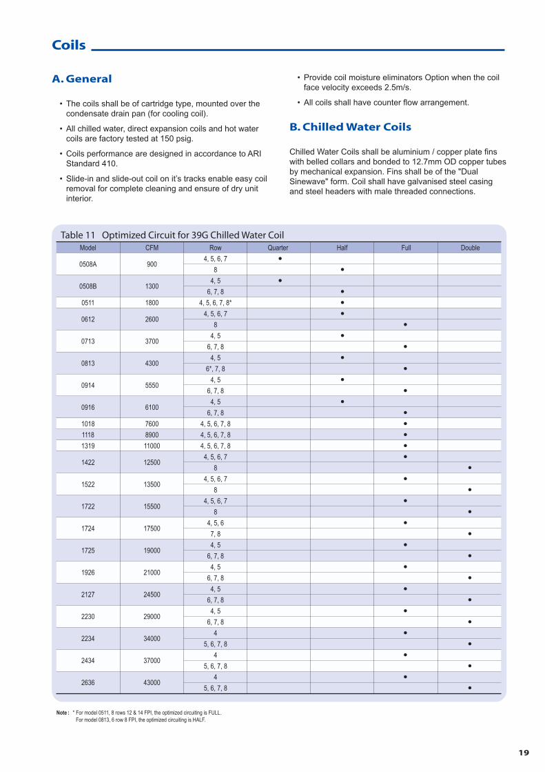
Table 11 Optimized Circuit for 39G Chilled Water Coil
Note : * For model 0511, 8 rows 12 & 14 FPI, the optimized circuiting is FULL.
For model 0813, 6 row 8 FPI, the optimized circuiting is HALF.
A. General
• The coils shall be of cartridge type, mounted over the
condensate drain pan (for cooling coil).
• All chilled water, direct expansion coils and hot water
coils are factory tested at 150 psig.
• Coils performance are designed in accordance to ARI
Standard 410.
• Slide-in and slide-out coil on it’s tracks enable easy coil
removal for complete cleaning and ensure of dry unit
interior.
• Provide coil moisture eliminators Option when the coil
face velocity exceeds 2.5m/s.
• All coils shall have counter flow arrangement.
B. Chilled Water Coils
Chilled Water Coils shall be aluminium / copper plate fins
with belled collars and bonded to 12.7mm OD copper tubes
by mechanical expansion. Fins shall be of the "Dual
Sinewave" form. Coil shall have galvanised steel casing
and steel headers with male threaded connections.

20
Coils
Model CFM Row Quarter Half Full Connection Size
0508A 900
1 1 1/2" BSP
2 1 1/2" BSP
0508B 1300
1 1 1/2" BSP
2 1 1/2" BSP
0511 1800
1 1 1/2" BSP
2 1 1/2" BSP
0612 2600
1 1 1/2" BSP
2 1 1/2" BSP
0713 3700 1, 2 1 1/2" BSP
0813 4300 1, 2 1 1/2" BSP
0914 5550 1, 2 1 1/2" BSP
0916 6100 1, 2 1 1/2" BSP
1018 7600
1 1 1/2" BSP
2 1 1/2" BSP
1118 8900
1 1 1/2" BSP
2 1 1/2" BSP
1319 11000
1 1 1/2" BSP
2 1 1/2" BSP
1422 12500
1 1 1/2" BSP
2 1 1/2" BSP
1522 13500
1 1 1/2" BSP
2 1 1/2" BSP
1722 15500
1 1 1/2" BSP
2 1 1/2" BSP
1724 17500
1 1 1/2" BSP
2 1 1/2" BSP
1725 19000
1 1 1/2" BSP
2 1 1/2" BSP
1926 21000
1 1 1/2" BSP
2 1 1/2" BSP
2127 24500
1 1 1/2" BSP
2 1 1/2" BSP
2230 29000
1 1 1/2" BSP
2 1 1/2" BSP
2234 34000
1 1 1/2" BSP
2 1 1/2" BSP
2434 37000
1 1 1/2" BSP
2 1 1/2" BSP
2636 43000
1 1 1/2" BSP
2 1 1/2" BSP
Table 12 Optimized Circuit for 39G Hot Water Coil
Working pressure shall be 2060 kPag at 93˚C. Coils shall
be drainable and have non air trapping circuits. No
turbulence promoting devices will be permitted inside the
tubes. Headers shall have drain and vent connections.
Chilled Water Coils offerings shall be as follows:
i) No. of rows: 4, 5, 6, 7 and 8
ii) Optimized coil circuiting
iii) 8, 10, 12 and 14 FPI
iv) 0.016" tube thickness available
v) 1/2" tube diameter standard
vi) Aluminium (standard) or copper (option) fins available
C. Hot Water Coil
Hot water coils shall be constructed similar to the chilled
water coil except that the maximum working pressure shall
be 1200 kPag at 205˚C.
Hot Water Coils offerings shall be as follows:
i) 1 and 2 rows
ii) Optimized coil circuiting
iii) 8, 10, 12 and 14 FPI
iv) 0.016" tube thickness available
v) 1/2" tube diameter standard
vi) Aluminium (standard) or copper (option) fins available

21
Model Row Half Full Suction Pipe Diameter Liquid Diameter
0508A 4, 6 7/8" 7/8"
0508B 4, 6 7/8" 7/8"
0511 4, 6 7/8" 7/8"
0612 4, 6 1 3/8" 1 1/8"
0713 4, 6 1 3/8" 1 1/8"
0813 4, 6 1 3/8" 1 1/8"
0914 4, 6 1 3/8" 1 1/8"
0916 4, 6 1 5/8" 1 1/8"
1018 4, 6 1 5/8" 1 1/8"
1118 4, 6 1 5/8" 1 1/8"
1319 4, 6 1 5/8" 1 1/8"
1422 4, 6 1 5/8" 1 1/8"
1522 4, 6 1 5/8" 1 1/8"
1722 4, 6 2" 1 3/8"
1724 4, 6 2" 1 3/8"
1725 4, 6 2 1/8" 1 3/8"
1926 4, 6 2 1/8" 1 3/8"
2127 4, 6 1 5/8" and 2" 1 1/8" and 1 3/8"
2230 4, 6 1 5/8" and 2 1/8" 1 1/8" and 1 3/8"
2234 4, 6 1 5/8" and 2 1/8" 1 1/8" and 1 3/8"
2434 4, 6 1 5/8" and 2 1/2" 1 1/8" and 1 3/8"
2636 4, 6 2" and 2 1/2" 1 1/8" and 1 3/8"
Table 13 Optimized Circuit for 39G Direct Expansion Coil
Coils
D. Direct Expansion Coil
Direct Expansion Coil shall have aluminium/copper fins
with belled collars and bonded 12.7mm OD copper tubes
by mechanical expansion. Fins shall be of the "Dual
Sinewave" form. Coils shall be provided with brass
distributors with sweat type connections. Coils shall have
full face active area with intertwined circuits for equal
loading on each circuit. Suction and metering valve
connection shall be on the same end. After leak testing, coil
shall be charged with dry air.
Direct Expansion offerings shall be as follows:
i) 4 and 6 rows
ii) Optimized coil circuiting (Both row and face split)
iii) 8, 10, 12 and 14 FPI
iv) 0.016" tube thickness available
v) 1/2" tube diameter standard
vi) Aluminium (standard) or sopper (sption) fins available
E. Condensate Drain Pan
The condensate drain pan shall be powder painted
galvanized steel and furnished with one female threaded
pipe connection of 43mm OD. The condensate drain pan
shall be constructed in sloped type with bottom drain outlet
to ensure complete drainage and meet ASHRAE 62-89.
The drain pan width covers the coil total length ensuring
optimum condensate collecting on both the return bends
and header side. Slider is welded at drain pan for easier
coil removal.
F. Coil Weight
The weight of the coil section is tabulated in Table 14.
G. Connection Outline
The coils connection position and diameter are shown in
Tables 19 to 20.

22
Co
ils
N
ote
:
1. A
ll co
ils a
re o
f 13m
m O
D c
oppe
r tu
bes
with
alu
min
ium
pla
te fi
n co
nstr
uctio
n.
2.
To
estim
ate
the
wei
ght o
f wat
er c
onte
nt (
kg)
use
: Fac
e ar
ea (
sq.m
) x
no. o
f row
s x
7.0
kg/s
q.m
3.
To
estim
ate
dry
coil
wei
ght (
kg)
for
copp
er p
late
fin
cons
truc
tion,
use
the
abov
e da
ta (
kg)
x 3.
3
N
o. o
f Row
1
2 4
5 6
7 8
4 6
Ty
pe o
f Coi
l H
ot W
ater
C
hille
d W
ater
D
irect
Exp
ansi
on
F
ins/
Inch
8
10
12
14
8 10
12
14
8
10
12
14
8 10
12
14
8
10
12
14
8 10
12
14
8
10
12
14
8 10
12
14
8
10
12
14
Tab
le 1
4 C
oil
Wei
gh
t
05
08A
0.
170
14
14
15
15
16
16
16
16
18
18
19
19
05
08B
0.
246
16
16
17
17
18
18
19
19
21
22
22
23
05
11
0.34
0 19
19
19
19
21
21
22
22
25
26
27
28
06
12
0.49
1 22
22
23
23
26
26
27
27
32
34
35
36
07
13
0.69
9 27
27
28
28
31
31
32
34
41
42
44
45
08
13
0.81
2 30
30
31
31
35
36
37
38
46
48
50
51
09
14
1.04
8 41
42
42
43
48
49
51
52
55
58
60
62
09
16
1.15
2 43
44
44
45
51
52
53
54
59
61
64
66
10
18
1.43
6 48
49
49
50
58
59
61
62
77
80
83
86
11
1 8
1.68
1 53
54
55
56
64
66
68
70
87
90
94
98
13
19
2.07
8 61
62
64
65
75
77
80
82
10
3 10
7 11
2 11
6
14
22
2.36
0 69
71
72
74
85
88
90
93
11
7 12
2 12
7 13
2
15
22
2.55
0 75
77
78
80
92
95
98
10
1 12
6 13
1 13
7 14
2
17
22
2.93
0 86
88
90
92
10
6 10
9 11
2 11
5 14
5 15
1 15
8 16
3
17
24
3.30
0 97
99
10
7 10
3 11
9 12
3 12
6 13
0 16
4 17
0 17
8 18
4
17
25
3.59
0 10
5 10
7 11
0 11
2 12
9 13
3 13
7 14
2 17
8 18
5 19
3 20
0
19
26
3.96
0 11
6 11
9 12
1 12
4 14
3 14
7 15
2 15
6 19
6 20
4 21
4 22
1
21
27
4.62
0 13
6 13
9 14
2 14
5 16
7 17
2 17
7 18
2 22
9 23
8 24
9 25
8
22
30
5.47
0 16
1 16
4 16
7 17
1 19
8 20
4 21
0 21
6 27
1 28
2 29
5 30
6
22
34
6.42
0 18
8 19
2 19
7 20
1 23
2 23
9 24
6 25
3 31
8 33
0 34
6 35
8
24
34
6.99
0 20
5 20
9 21
4 21
8 25
2 26
0 26
5 27
6 34
6 36
0 37
6 39
0
26
36
8.12
0 23
8 24
3 24
9 25
4 29
3 30
2 31
1 32
0 40
2 41
8 43
7 45
3
19
20
20
21
21
21
22
22
22
22
23
24
23
24
24
25
25
26
26
27
26
27
28
29
28
29
30
31
30
31
32
33
32
34
35
36
36
37
38
40
39
41
42
44
42
44
46
48
45
47
49
51
50
52
55
57
55
58
60
63
51
54
56
58
57
60
62
65
62
65
69
72
62
65
68
71
77
80
83
87
84
88
92
96
67
70
73
76
82
85
89
93
89
94
98
10
2
86
90
94
98
96
10
1 10
5 11
0 10
5 11
1 11
6 12
2
98
10
3 10
7 11
2 10
9 11
5 12
0 12
6 12
0 12
7 13
3 14
0
11
7 12
2 12
8 13
4 13
0 13
7 14
4 15
1 14
4 15
2 16
0 16
8
13
3 13
9 14
5 15
2 14
8 15
6 16
4 17
1 16
4 17
3 18
2 19
1
14
4 15
0 15
7 16
4 15
9 16
8 17
7 18
5 17
7 18
6 19
6 20
6
16
5 17
2 18
0 18
9 18
3 19
3 20
3 21
3 20
3 21
4 22
5 23
7
18
6 19
4 20
3 21
3 20
7 21
8 22
9 24
0 22
9 24
2 25
4 26
7
20
2 21
1 22
1 23
1 22
4 23
6 24
9 26
1 24
9 26
2 27
6 29
0
22
3 23
3 24
4 25
6 24
8 26
1 27
5 28
8 27
5 29
0 30
5 32
0
26
0 27
1 28
5 29
8 28
9 30
5 32
0 33
6 23
0 33
8 35
6 37
4
30
8 32
1 33
7 35
3 34
2 36
1 37
9 39
8 37
9 40
0 42
1 44
3
36
1 37
7 39
5 41
4 40
2 42
3 44
5 46
6 44
5 46
9 49
4 51
9
39
3 41
0 43
0 45
0 43
7 46
1 48
4 50
8 48
4 51
1 53
8 56
5
45
7 47
6 50
0 52
3 50
8 53
5 56
2 59
0 56
2 59
4 62
5 65
6
23
24
24
25
18
18
19
19
21
21
22
22
28
29
30
31
21
22
22
23
25
26
26
27
35
36
38
39
25
26
27
28
30
31
32
33
46
48
50
52
32
34
35
36
39
41
42
44
60
63
66
69
41
42
44
45
50
52
55
57
68
71
75
78
46
48
50
51
57
60
62
65
91
95
10
0 10
4 55
58
60
62
77
80
83
87
97
10
2 10
7 11
2 59
61
64
66
82
85
89
93
11
5 12
1 12
8 13
4 77
80
83
86
96
10
1 10
5 11
0
13
2 13
9 14
6 15
4 87
90
94
98
10
9 11
5 12
0 12
6
15
8 16
7 17
6 18
5 10
3 10
7 11
2 11
6 13
0 13
7 14
4 15
1
17
9 19
0 20
0 21
0 11
7 12
2 12
7 13
2 14
8 15
6 16
4 17
1
19
4 20
5 21
6 22
7 12
6 13
1 13
7 14
2 15
9 16
8 17
7 18
5
22
2 23
5 24
8 26
0 14
5 15
1 15
8 16
3 18
3 19
3 20
3 21
3
25
1 26
5 28
0 29
4 16
4 17
0 17
8 18
4 20
7 21
8 22
9 24
0
27
3 28
8 30
4 31
9 17
8 18
5 19
3 20
0 22
4 23
6 24
9 26
1
30
1 31
9 33
6 35
3 19
6 20
4 21
4 22
1 24
8 26
1 27
5 28
8
35
2 37
2 39
2 41
2 22
9 23
8 24
9 25
8 28
9 30
5 32
0 33
6
41
6 44
0 46
4 48
7 27
1 28
2 29
5 30
6 34
2 36
1 37
9 39
8
48
8 51
6 54
4 57
1 31
8 33
0 34
6 35
8 40
2 42
3 44
5 46
6
53
1 56
1 59
2 62
2 34
6 36
0 37
6 39
0 43
7 46
1 48
4 50
8
61
7 65
2 68
7 72
3 40
2 41
8 43
7 45
3 50
8 53
5 56
2 59
0
Uni
tS
ize
Fac
e A
rea
(sq.
m)
Est
imat
ed D
ry C
oil W
eigh
t (kg
)

23
Co
ils
4
Row
Coi
l 5
Row
Coi
l 6
Row
Coi
l 7
Row
Coi
l 8
Row
Coi
l
Tab
le 1
5 C
hill
ed W
ater
Co
il - H
ori
zon
tal D
raw
Th
ru A
HU
- 25
mm
Cas
ing
A
B
C
D
E
F
A
B
C
D
E
F
05
08A
35
3 71
0 20
8 17
8 23
8 1
1/2"
35
3 71
0 20
8 17
8 25
7 1
1/2"
05
08B
35
3 71
0 20
8 17
8 23
8 1
1/2"
35
3 71
0 20
8 17
8 25
7 1
1/2"
05
11
353
710
208
178
238
1 1/
2"
353
710
208
178
257
1 1/
2"
06
12
480
810
208
178
238
1 1/
2"
480
810
208
178
257
1 1/
2"
07
13
544
910
208
178
238
1 1/
2"
544
910
208
178
257
1 1/
2"
08
13
671
1010
20
8 17
8 23
8 1
1/2"
67
1 10
10
208
178
257
1 1/
2"
09
14
798
1110
20
8 17
8 23
8 1
1/2"
79
8 11
10
208
178
257
1 1/
2"
09
16
798
1110
20
8 17
8 23
8 1
1/2"
79
8 11
10
208
178
257
1 1/
2"
10
18
847
1210
21
5 17
8 23
8 2"
84
7 12
10
215
178
257
2"
11
1 8
974
1310
21
5 17
8 23
8 2"
97
4 13
10
215
178
257
2"
13
19
1164
15
10
215
178
238
2"
1164
15
10
215
178
257
2"
14
22
1179
16
10
221
178
238
2 1/
2"
1179
16
10
221
178
257
2 1/
2"
15
22
1278
17
10
221
178
238
2 1/
2"
1278
17
10
221
178
257
2 1/
2"
17
22
1456
19
10
228
198
277
3"
1456
19
10
228
198
297
3"
17
24
1456
19
10
228
198
277
3"
1456
19
10
228
198
297
3"
17
25
1456
19
10
228
198
277
3"
1456
19
10
228
198
297
3"
19
26
1647
21
10
228
198
277
3"
1647
21
10
228
198
297
3"
*2
127
643
2310
22
8 17
8 27
7 2
1/2"
64
3 23
10
228
178
297
2 1/
2"
1139
3"
11
39
3"
*2
230
770
2410
22
8 17
8 27
7 2
1/2"
77
0 24
10
228
178
297
2 1/
2"
1139
3"
11
39
3"
*2
234
770
2410
22
8 17
8 27
7 2
1/2"
77
0 24
10
228
178
297
2 1/
2"
1139
3"
11
39
3"
*2
434
643
2610
22
8 17
8 27
7 2
1/2"
64
3 26
10
228
178
297
2 1/
2"
1456
3"
14
56
3"
*2
636
834
2810
22
8 17
8 27
7 2
1/2"
83
4 28
10
228
178
297
2 1/
2"
1456
3"
14
56
3"
A
B
C
D
E
F
A
B
C
D
E
F
35
3 71
0 20
8 17
8 27
7 1
1/2"
35
3 71
0 20
8 17
8 29
7 1
1/2"
35
3 71
0 20
8 17
8 27
7 1
1/2"
35
3 71
0 20
8 17
8 29
7 1
1/2"
35
3 71
0 20
8 17
8 27
7 1
1/2"
35
3 71
0 20
8 17
8 29
7 1
1/2"
48
0 81
0 20
8 17
8 27
7 1
1/2"
48
0 81
0 20
8 17
8 29
7 1
1/2"
54
4 91
0 20
8 17
8 27
7 1
1/2"
54
4 91
0 20
8 17
8 29
7 1
1/2"
67
1 10
10
208
178
277
1 1/
2"
671
1010
20
8 17
8 29
7 1
1/2"
79
8 11
10
215
178
277
2"
798
1110
21
5 17
8 29
7 2"
79
8 11
10
215
178
277
2"
798
1110
21
5 17
8 29
7 2"
84
7 12
10
215
178
277
2"
847
1210
21
5 17
8 29
7 2"
97
4 13
10
215
178
277
2"
974
1310
21
5 17
8 29
7 2"
11
64
1510
22
1 17
8 27
7 2
1/2"
11
64
1510
22
1 17
8 29
7 2
1/2"
11
79
1610
22
1 17
8 27
7 2
1/2"
11
79
1610
22
1 17
8 29
7 2
1/2"
12
78
1710
22
1 17
8 27
7 2
1/2"
12
78
1710
22
1 17
8 29
7 2
1/2"
14
56
1910
22
8 19
8 27
7 3"
14
56
1910
22
8 19
8 29
7 3"
14
56
1910
22
8 19
8 27
7 3"
14
56
1910
22
8 19
8 29
7 3"
14
56
1910
22
8 19
8 27
7 3"
14
56
1910
22
8 19
8 29
7 3"
16
47
2110
22
8 19
8 29
7 3"
16
47
2110
22
8 19
8 29
7 3"
64
3 23
10
228
178
277
2 1/
2"
643
2310
22
8 17
8 29
7 2
1/2"
11
39
3"
1139
3"
77
0 24
10
228
178
277
2 1/
2"
770
2410
22
8 17
8 29
7 2
1/2"
11
39
3"
1139
3"
77
0 24
10
228
178
277
2 1/
2"
770
2410
22
8 17
8 29
7 2
1/2"
11
39
3"
1139
3"
64
3 26
10
228
178
277
2 1/
2"
643
2610
22
8 17
8 29
7 2
1/2"
14
56
3"
1456
3"
8 3
4 28
10
228
178
277
2 1/
2"
834
2810
22
8 17
8 29
7 2
1/2"
14
56
3"
1456
3"
A
B
C
D
E
F
35
3 71
0 20
8 17
8 31
7 1
1/2"
35
3 71
0 20
8 17
8 31
7 1
1/2"
35
3 71
0 20
8 17
8 31
7 1
1/2"
48
0 81
0 20
8 17
8 31
7 1
1/2"
54
4 91
0 20
8 17
8 31
7 1
1/2"
67
1 10
10
208
178
317
1 1/
2"
79
8 11
10
215
178
317
2"
79
8 11
10
215
178
317
2"
84
7 12
10
215
178
317
2"
97
4 13
10
215
178
317
2"
11
64
1510
22
1 17
8 31
7 2
1/2"
11
79
1610
22
1 17
8 31
7 2
1/2"
12
78
1710
22
1 17
8 31
7 2
1/2"
14
56
1910
22
8 19
8 29
7 3"
14
56
1910
22
8 19
8 29
7 3"
14
56
1910
22
8 19
8 29
7 3"
16
47
2110
22
8 19
8 29
7 3"
64
3 23
10
228
178
297
2 1/
2"
11
39
3"
77
0 24
10
228
178
297
2 1/
2"
11
39
3"
77
0 24
10
228
178
297
2 1/
2"
11
39
3"
64
3 26
10
228
178
297
2 1/
2"
14
56
3"
8 3
4 28
10
228
178
297
2 1/
2"
14
56
3"
R
em
ark
s :
1. R
efer
sch
emat
ic d
raw
ing
page
no.
45
for
spec
ific
dim
ensi
on.
2.
* A
HU
with
2 c
oil b
lock
s.
3.
Top
dim
ensi
on r
efer
to th
e up
per
coil;
bot
tom
dim
ensi
on r
efer
to th
e lo
wer
coi
l (A
& F
dim
ensi
on).
Uni
t siz
e39
G
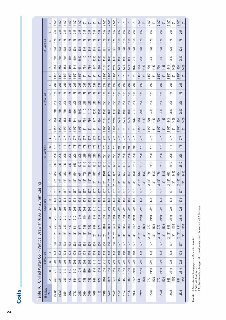
24
4
Row
Coi
l 5
Row
Coi
l 6
Row
Coi
l 7
Row
Coi
l 8
Row
Coi
l
Tab
le 1
6 C
hill
ed W
ater
Co
il - V
erti
cal D
raw
Th
ru A
HU
- 25
mm
Cas
ing
A
B
C
D
E
F
A
B
C
D
E
F
05
08A
35
3 71
0 20
8 17
8 23
8 1
1/2"
35
3 71
0 20
8 17
8 25
7 1
1/2"
05
08B
35
3 71
0 20
8 17
8 23
8 1
1/2"
35
3 71
0 20
8 17
8 25
7 1
1/2"
05
11
353
710
208
178
238
1 1/
2"
353
710
208
178
257
1 1/
2"
06
12
480
810
208
178
238
1 1/
2"
480
810
208
178
257
1 1/
2"
07
13
544
910
208
178
238
1 1/
2"
544
910
208
178
257
1 1/
2"
08
13
671
1010
20
8 17
8 23
8 1
1/2"
67
1 10
10
208
178
257
1 1/
2"
09
14
798
1110
20
8 17
8 23
8 1
1/2"
79
8 11
10
208
178
257
1 1/
2"
09
16
798
1110
20
8 17
8 23
8 1
1/2"
79
8 11
10
208
178
257
1 1/
2"
10
18
847
1210
21
5 17
8 23
8 2"
84
7 12
10
215
178
257
2"
11
1 8
974
1310
21
5 17
8 23
8 2"
97
4 13
10
215
178
257
2"
13
19
1164
15
10
215
178
238
2"
1164
15
10
215
178
257
2"
14
22
1179
16
10
221
178
238
2 1/
2"
1179
16
10
221
178
257
2 1/
2"
15
22
1278
17
10
221
178
238
2 1/
2"
1278
17
10
221
178
257
2 1/
2"
17
22
1456
19
10
228
198
277
3"
1456
19
10
228
198
297
3"
17
24
1456
19
10
228
198
277
3"
1456
19
10
228
198
297
3"
17
25
1456
19
10
228
198
277
3"
1456
19
10
228
198
297
3"
19
26
1647
21
10
228
198
277
3"
1647
21
10
228
198
297
3"
*2
127
643
2310
22
8 17
8 27
7 2
1/2"
64
3 23
10
228
178
297
2 1/
2"
1139
3"
11
39
3"
*2
230
770
2410
22
8 17
8 27
7 2
1/2"
77
0 24
10
228
178
297
2 1/
2"
1139
3"
11
39
3"
*2
234
770
2410
22
8 17
8 27
7 2
1/2"
77
0 24
10
228
178
297
2 1/
2"
1139
3"
11
39
3"
*2
434
643
2610
22
8 17
8 27
7 2
1/2"
64
3 26
10
228
178
297
2 1/
2"
1456
3"
14
56
3"
*2
636
834
2810
22
8 17
8 27
7 2
1/2"
83
4 28
10
228
178
297
2 1/
2"
1456
3"
14
56
3"
A
B
C
D
E
F
A
B
C
D
E
F
35
3 71
0 20
8 17
8 27
7 1
1/2"
35
3 71
0 20
8 17
8 29
7 1
1/2"
35
3 71
0 20
8 17
8 27
7 1
1/2"
35
3 71
0 20
8 17
8 29
7 1
1/2"
35
3 71
0 20
8 17
8 27
7 1
1/2"
35
3 71
0 20
8 17
8 29
7 1
1/2"
48
0 81
0 20
8 17
8 27
7 1
1/2"
48
0 81
0 20
8 17
8 29
7 1
1/2"
54
4 91
0 20
8 17
8 27
7 1
1/2"
54
4 91
0 20
8 17
8 29
7 1
1/2"
67
1 10
10
208
178
277
1 1/
2"
671
1010
20
8 17
8 29
7 1
1/2"
79
8 11
10
215
178
277
2"
798
1110
21
5 17
8 29
7 2"
79
8 11
10
215
178
277
2"
798
1110
21
5 17
8 29
7 2"
84
7 12
10
215
178
277
2"
847
1210
21
5 17
8 29
7 2"
97
4 13
10
215
178
277
2"
974
1310
21
5 17
8 29
7 2"
11
64
1510
22
1 17
8 27
7 2
1/2"
11
64
1510
22
1 17
8 29
7 2
1/2"
11
79
1610
22
1 17
8 27
7 2
1/2"
11
79
1610
22
1 17
8 29
7 2
1/2"
12
78
1710
22
1 17
8 27
7 2
1/2"
12
78
1710
22
1 17
8 29
7 2
1/2"
14
56
1910
22
8 19
8 27
7 3"
14
56
1910
22
8 19
8 29
7 3"
14
56
1910
22
8 19
8 27
7 3"
14
56
1910
22
8 19
8 29
7 3"
14
56
1910
22
8 19
8 27
7 3"
14
56
1910
22
8 19
8 29
7 3"
16
47
2110
22
8 19
8 27
7 3"
16
47
2110
22
8 19
8 29
7 3"
64
3 23
10
228
178
277
2 1/
2"
643
2310
22
8 17
8 29
7 2
1/2"
11
39
3"
1139
3"
77
0 24
10
228
178
277
2 1/
2"
770
2410
22
8 17
8 29
7 2
1/2"
11
39
3"
1139
3"
77
0 24
10
228
178
277
2 1/
2"
770
2410
22
8 17
8 29
7 2
1/2"
11
39
3"
1139
3"
64
3 26
10
228
178
277
2 1/
2"
643
2610
22
8 17
8 29
7 2
1/2"
14
56
3"
1456
3"
8 3
4 28
10
228
178
277
2 1/
2"
834
2810
22
8 17
8 29
7 2
1/2"
14
56
3"
1456
3"
A
B
C
D
E
F
35
3 71
0 20
8 17
8 31
7 1
1/2"
35
3 71
0 20
8 17
8 31
7 1
1/2"
35
3 71
0 20
8 17
8 31
7 1
1/2"
48
0 81
0 20
8 17
8 31
7 1
1/2"
54
4 91
0 20
8 17
8 31
7 1
1/2"
67
1 10
10
208
178
317
1 1/
2"
79
8 11
10
215
178
317
2"
79
8 11
10
215
178
317
2"
84
7 12
10
215
178
317
2"
97
4 13
10
215
178
317
2"
11
64
1510
22
1 17
8 31
7 2
1/2"
11
79
1610
22
1 17
8 31
7 2
1/2"
12
78
1710
22
1 17
8 31
7 2
1/2"
14
56
1910
22
8 19
8 29
7 3"
14
56
1910
22
8 19
8 29
7 3"
14
56
1910
22
8 19
8 29
7 3"
16
47
2110
22
8 19
8 29
7 3"
64
3 23
10
228
178
297
2 1/
2"
11
39
3"
77
0 24
10
228
178
297
2 1/
2"
11
39
3"
77
0 24
10
228
178
297
2 1/
2"
11
39
3"
64
3 26
10
228
178
297
2 1/
2"
14
56
3"
8 3
4 28
10
228
178
297
2 1/
2"
14
56
3"
R
em
ark
s :
1. R
efer
sch
emat
ic d
raw
ing
page
no.
45
for
spec
ific
dim
ensi
on.
2.
* A
HU
with
2 c
oil b
lock
s.
3.
Top
dim
ensi
on r
efer
to th
e up
per
coil;
bot
tom
dim
ensi
on r
efer
to th
e lo
wer
coi
l (A
& F
dim
ensi
on).
Uni
t Siz
e39
G
Co
ils

25
C
A
A
B
E
D
1 1/2" FPT DRAIN PIPE
AIR FLOW
Unit Size: 2127 - 2636
OUTSIDE
DUCT
FRONT
HEADER SIZING
F" MPT
50 mm DIA LIFTING HOLES
AT FOUR CORNERS
C
A B
E
D
1 1/2" FPT DRAIN PIPE
AIR FLOW
Unit Size: 0508A - 1926
OUTSIDE
DUCT
FRONT
HEADER SIZING
F" MPT
50 mm DIA LIFTING HOLES
AT FOUR CORNERS
C
A
A
B
E
DHEADER SIZING
F" MPT
1 1/2" FPT DRAIN PIPE50 mm DIA LIFTING HOLES
AT FOUR CORNERS
AIR FLOW
FRONT
OUTSIDE
DUCT
Unit Size: 2127 - 2636
C
A B
E
DHEADER SIZING
F" MPT
1 1/2" FPT DRAIN PIPE50 mm DIA LIFTING HOLES
AT FOUR CORNERS
AIR FLOW
FRONT
OUTSIDE
DUCT
Unit Size: 0508A - 1926
Figure 9 Connection Outline
Coils

26
Mixing Box
Air leakage using damper area ration and a perimeter gap
of 3mm between blade and frame results in leakage rate of
approximately 3% as a complete system when either one
damper assembly is completely closed.
The damper are located on the outside of mixing boxes
and the standard damper location shall be top and rear.
Interconnection between outdoor air and return air damper
is made with push rods installed in the factory. The damper
blades for each assembly shall be connected using
linkages on one side of the damper frames ensuring its
synchronous movement.
The damper frame is U-formed/flanged but not drilled
which serves as a flange or duct work connection.
Unit Size Module Opening
39G Length (M) H X W (mm)
0508A/B 6 480 X 726
0511 6 480 X 1026
0612 6 480 X 1126
0713 6 480 X 1226
0813 6 480 X 1226
0914 6 480 X 1326
0916 6 480 X 1526
1018 6 480 X 1726
1118 6 480 X 1726
1319 6 480 X 1826
1422 9 795 X 2126
1522 9 795 X 2126
1722 9 795 X 2126
1724 9 795 X 2326
1725 9 795 X 2426
1926 13 1267 X 2526
2127 13 1267 X 2626
2230 13 1267 X 2926
2234 13 1267 X 3326
2434 13 1267 X 3326
2636 13 1267 X 3526
Table 19 Mixing Box Section in Module
Note : 1. The above dimensions applicable for 39GA 25mm
2. W1 = 200mm Z = 82mm (0508A to 1319) or
X = 36mm (0508A to 1725) or 67mm (1422 to 1725) or
15.2mm (1926 to 2636) 15.2mm (1926 to 2636)
Y = 36mm
Z
X
Y
H
W
W1
Figure 11
Table 20 Mixing Box Dampers Friction LossVelocity (m/s)
1.50 2.00 2.50 3.00 3.50 4.00
Mixing Box (Pa) 2.49 4.98 9.96 12.46 14.95 19.93
Section
A. General
Mixing box shall have parallel blades, interconnected
opposing action between outdoor air and return air
dampers. Dampers blades shall be brake formed for
stiffness and shall be spot welded to a 13mm O.D. steel
rods rotating in nylon bushings press-seated in rigid
damper frames. Damper shall be fabricated from 1.2mm
(18 gauge) thick galvannealed steel sheet and the damper
frame of 1.2mm (18 gauge) thick with a finishing of oven
cured polyester based powder paint.
Dampers shall be sectionalized to limit blade length to not
more than 1526mm in order to prevent excessive blade
warping and ensure tight closure. Outdoor air and return air
dampers shall be of the same area (Figure 10 and Table
19).

27
Filter
Filter Face Velocity (m/s) 1.5 2.0 2.5 3.0 3.5
HVF 2" thick 85% gravimetric 8.96 12.46 19.93 27.40 37.40
BF 600mm bag length 95% gravimetric 9.96 14.95 29.89 47.33 69.75
Table 17 Filter Pressure Drop (Pa)
Note : Data shown is for clean filter, based on synthetic fibre material. The normal allowable pressure drop for dirty filter should not exceed 300Pa (1.2" W.G).
A. General
The types of filters offered in 39G are as follows:
i) HVF - High velocity filters
ii) BF - Bag filters
Each filter type selected shall include a 39G section with
the appropriate tracks. The filter section shall be similar in
construction as the other 39G sections. The tracks supplied
shall be in accordance to the HVAC filter standard sizes
and its gravimetric efficiency per ASHRAE 52-76.
B. High Velocity Filter (HVF)
Commonly known as pre-filter, the HVF is offered with a
thickness of either 25mm or 50mm. The standard
gravimetric efficiency shall be 85% with 70% optional and
media are washable made of aluminium or synthetic fibre.
The HVF can be installed to the 39G as follows:
i) Front loading with track only (i.e. free return
application)
ii) Front loading/withdrawal filter track within 2 module
length section. When require filter section which must
able to accessible for filter loading/withdrawal by
access door at return duct (i.e. duct return application)
or access door at mixing box.
The frames and tracks are fabricated of 1.25mm (18
gauge) thick galvanized steel sheet.
C. Bag Filter (BF)
The bag filter is normally used as 2nd stage filtration
media. The factory standard efficiency shall be 95%
gravimetric efficiency. Media are disposable type. The bag
filter media shall be synthetic fibre of 600mm bag length
and 25mm thick aluminium frame.
As a standard, the BF section comprises of 6 module, by
front loading/withdrawal method.
D. Friction Pressure Drop
Due to filter media resists to the air flow resulting in static
loss, therefore refer to Table 23 on the respective static
pressure loss against velocity (interpolation is permissible).

YOUR CARRIER MAN :
∫√‘…—∑ ·§‡√’¬√å (ª√–‡∑»‰∑¬) ®”°—¥™—Èπ 14-15 Õ“§“√‡π™—Ëπ ∑“«‡«Õ√å 46/63-74 ∂.∫“ßπ“-µ√“¥ °¡. 4.5 ∫“ßπ“ °√ÿ߇∑æœ 10260 ‚∑√. 0-2751-4777 ·ø°´å: 0-2751-4778
Carrier (Thailand) Ltd.14-15th Fl., Nation Tower,
46/63-74 Bangna-Trad Road Km. 4.5, Bangna,
Bangkok 10260 Thailand
Tel.: 0-2751-4777 Fax: 0-2751-4778
39G/03/06
Carrier reserves the right to make changes in specifications without prior notice.
∫√‘…—∑œ ¢Õ ß«π ‘∑∏‘Ï∑’Ë®–‡ª≈’ˬπ·ª≈ß√“¬≈–‡Õ’¬¥¢â“ßµâπ ‚¥¬¡‘µâÕß·®âß„Àâ∑√“∫≈à«ßÀπâ“
Filter
Table 18 Filter Type, Dimension and Quantity for Each AHU SizeModel
0508A 0508B 0511 0612 0713 0813 0914 0916 1018 1118 1319
a ) 2" HVF Washable
( H245XW495 ) mm 1 1 1 - - - - - - - -
( H495XW495 ) mm 1 1 2 - - - - - - - -
( H295XW595 ) mm - - - 1 - - 2 3 3 3 -
( H595XW595 ) mm - - - 1 2 2 2 2 3 3 6
b ) Bag Filter
( H245XW495 ) mm - - - - - - - - - - -
( H495XW495 ) mm - - - - - - - - - - -
( H295XW595 ) mm - - - 1 - - 2 3 3 3 -
( H595XW595 ) mm - - - 1 2 2 2 2 3 3 6
Filter Type
Model
1422 1522 1722 1724 1725 1926 2127 2230 2234 2434 2636
a ) 2" HVF Washable
( H245XW495 ) mm - - - - - - - - - - -
( H495XW495 ) mm - - - - - - - - - - -
( H295XW595 ) mm 2 2 5 5 4 - 4 7 8 8 4
( H595XW595 ) mm 6 6 6 6 8 12 12 12 15 15 20
b ) Bag Filter
( H245XW495 ) mm - - - - - - - - - - -
( H495XW495 ) mm - - - - - - - - - - -
( H295XW595 ) mm 2 2 5 5 4 - 4 7 8 8 4
( H595XW595 ) mm 6 6 6 6 8 12 12 12 15 15 20
Filter Type
Remark : The bag filter media shall be synthetic fibre of 600 mm. bag length or less, in case of using bag length more than 600 mm.
Please consult your local CARRIER office to arrange for filter section to match with.