3d animation techniques on the i.mx31 pdk · 3d animation techniques on the i.mx31 pdk, rev. 0 2...
TRANSCRIPT
Freescale SemiconductorApplication Note
© Freescale Semiconductor, Inc., 2010. All rights reserved.
Animation techniques are essential 3D applications where a character or morphing objects are present, for example, games, simulation, and medical applications.
This application note intends to be a guide for picking and implementing a technique for animation.
The animation techniques presented in this application note are morphing, skeletal animation, and hierarchical animation. One technique cannot be qualified as the best technique. Each animation technique has its pros and cons especially with regard to storage, processing, or how good or realistic it may look.
Document Number: AN4044Rev. 0, 01/2010
Table of Contents1. Morphing . . . . . . . . . . . . . . . . . . . . . . . . . . . . . . . . . . 22. Hierarchical Animation . . . . . . . . . . . . . . . . . . . . . . . . 63. Skeletal Animation . . . . . . . . . . . . . . . . . . . . . . . . . . . 84. Comparison of Animation Techniques . . . . . . . . . . . 125. Conclusion . . . . . . . . . . . . . . . . . . . . . . . . . . . . . . . . 136. Revision History . . . . . . . . . . . . . . . . . . . . . . . . . . . . 14
3D Animation Techniques on the i.MX31 PDKby Multimedia Application Division
Freescale Semiconductor, Inc.Austin, TX

3D Animation Techniques on the i.MX31 PDK, Rev. 0
2 Freescale Semiconductor
Morphing
1 MorphingMorphing is the act of changing an object into another object. This technique is widely used to animate clothes, skin, face, and non-solid bodies. A 3D object is composed of an array of triangles, an array of normals to the triangle surface and texture coordinates. Normals are used for light refraction calculations. Triangles have three vertices. Each vertex is composed by a position in the 3D space (X, Y, Z component). Figure 1 shows a sample 3D object.
Figure 1. 3D Object
To morph a 3D object, keep the texture coordinates unchanged in the animation. Since the texture coordinates correspond to the vertex order, and morphing changes the vertex values not their order, no changes in the text coordinates need to be done. Normals can be changed in the same fashion as vertex values for a better looking animation. To morph a 3D object, each vertex position of a 3D object must move to another 3D object’s vertex position.
While morphing, some 3D objects are stored as key frames as shown in Figure 2. A morphing program references these key frames as a source (the first frame in the animation) or destiny (the last frame in the animation).
Figure 2. Key Frames
Moving each vertex in certain number of frames or over time shows intermediate frames (frames between key frames). This way an animation is created. Figure 3 shows a four frame animation between the first two key frames. Moving each vertex is achieved by interpolation over time or by the number of frames.

3D Animation Techniques on the i.MX31 PDK, Rev. 0
Freescale Semiconductor 3
Morphing
The two intermediate frames in Figure 3 are intermediate frames generated by a morphing program.
Figure 3. Intermediate Frames
1.1 Building a Morphing ProgramThe objective of a morphing program is to move each vertex from a source 3D object (a key frame) to a destiny 3D object (another key frame), thereby generating intermediate frames in the process.
The requirements are as follows:
• Loaded or built 3D objects that enable access to vertex information.
• OpenGL to paint the 3D objects.
The steps for initialization are as follows:
1. Load the 3D objects that work as key frames in the program.
2. Create a Temporal 3D object to store intermediate frames.
3. Create two pointers to vertex data to keep a continuous reference of the Source and Destiny 3D object.
4. Point Source and Destiny to the initial key frame and also make Temporal equal to the initial key frame.
Continuously draw the temporal 3D object and call an interpolation method. Animations can be triggered by buttons or by a routine in the drawing method. To do this, simply point Destiny to some other key frame vertex data.
1.2 Interpolation MethodsThe interpolation method is used to update the vertex information in the Temporal 3D object by following an interpolation function between Source and Destiny. Interpolation can be over time or by frames. It can also be linear or non linear.
1.2.1 Interpolation over TimeInterpolation based on time is based in milliseconds and is called Interpolation over time. When the animation is triggered, endTime must be set by adding the currentTime to the animationTime (endTime = currentTime + animationTime).

3D Animation Techniques on the i.MX31 PDK, Rev. 0
4 Freescale Semiconductor
Morphing
The interpolation function is based on a very simple statement: When time is up (endTime = currentTime), Temporal must be equal to Destiny and when animation begins (endTime-currentTime = animationTime), Temporal must be equal to Source.
Pseudocode for interpolationOvertime function is as follows:
interpolationOvertime(endTime){
If (currentTime<endTime){
Ω = currentTime/endTimeTemporal = Destiny*Ω + Source(1 - Ω)
}}
With this method the following is derived:
At the beginning of the animation
endTime-currentTime = animationTimeΩ = currentTime/(currentTime + endTime) = very small number≈0Temporal = Destiny * 0 +Source (1−0)Temporal = Source
At the end of the animation
endTime = currentTimeΩ = currentTime/currentTime = 1Temporal = Destiny * 1+Source (1−1)Temporal = Destiny
1.2.2 Interpolation by Number of FramesInterpolation based on the number of frames uses a variable to keep the number of frames nFrames. The count variable keeps track of the number of frames that have passed since the animation was triggered. When count equals one, Temporal must be equal to Source. When count equals nFrames, Temporal must be equal to Destiny.
Pseudocode for interpolation by number of frames is as follows:
interpolationBynFrames(){
if(count<nFrames){
Temporal+= (Destiny - Source)/nFrames;}
}
This approach is based on a simple principle
(1/nFrames)*nFrames = 1
which means, if
nFrames = 2, 1/2 + 1/2 = 1.
By adding fractions of Destiny-Source, Destiny is obtained.

3D Animation Techniques on the i.MX31 PDK, Rev. 0
Freescale Semiconductor 5
Morphing
NOTEWhen an animation is triggered Temporal = Source.
Then adding each fraction of nFrames is equal to:
Temporal += Destiny− Source
And since, Temporal = Source
Source += Destiny− Source = Destiny
1.2.3 Linear InterpolationLinear interpolation is going from source to destiny in a straight line or a slope. This is the way the prototypes are shown for interpolationOverTime() and interpolationBynFrames().
1.2.4 Non-Linear InterpolationAdding to functions results in a function mounted on the other. Figure 4 demonstrates how a signal is mounted on a slope.
Figure 4. Signal Mounted in a Slope
1.2.5 Sinusoidal InterpolationTo mount a sinusoidal to the interpolation function, add a simple sinusoidal function to the vertex data from the interpolation.
NOTEThe function must begin at 0 and end at 0 so that the morph is not affected by the mounted function.
Sinusoidal interpolation overtime function is as follows:
Temporal = Destiny*Ω + Source(1 - Ω) + sin(Π* Ω)
Pseudocode for sinusoidal interpolation frame is as follows:
Temporal+= (Destiny - Source)/nFrames;if (count<= nFrame/2){
Temporal+=sin(Π*(steps/totalsteps));}else{

3D Animation Techniques on the i.MX31 PDK, Rev. 0
6 Freescale Semiconductor
Hierarchical Animation
Temporal-=sin(Π*(steps/totalsteps));}
The implementations shown above are from 0 to Π.
2 Hierarchical AnimationHierarchical animation is a technique based on moving through an array of pivots in a hierarchical fashion and applying the basic operations of OpenGL. For a more detailed understanding of OpenGL, its basic operations and stacks, refer to Chapter 3 of OpenGL red book or a web page that covers these topics in a more extensive way.
Every 3D object has a pivot in which OpenGL operations are performed. A 3D object is built based on local coordinates. Local (0,0,0) on x,y,z is the pivot of a 3D object. The basic operations of OpenGL are rotate, translate, and scale. These operations must be performed in the ModelView matrix in order to apply them to a 3D object or a set of 3D objects. When one of these operations is called, the ModelView matrix is transformed. Depending on the order of the operations the user gets different results, as shown in the Figure 5 taken from the OpenGL red book.
OpenGL possess a matrix stack were transformations of the ModelView matrix are stored. To copy a matrix to the top of the stack use glPushMatrix(). To discard the top matrix of the stack use glPopMatrix(). This stack can be used to remember previous transformations of the ModelView matrix.
Using glTranslate(), glRotate(), glPushMatrix(), glPopMatrix() pivot points in a hierarchical fashion determines if the 3D objects would be moved and how much would they move.
Figure 5. Rotating First or Translating First
For good looking animations, build a hierarchy of pivots and separate a 3D object into several 3D objects. If a car needs to be animated, the whole car can be translated but the wheels do not move. To make the wheels move, make separate 3D objects of the wheels and rotate them in their own pivot with a hierarchical structure, so they look like they are spinning.

3D Animation Techniques on the i.MX31 PDK, Rev. 0
Freescale Semiconductor 7
Hierarchical Animation
2.1 Building a Hierarchical Animation ProgramThe following are the steps involved in building of hierarchical animation program:
The requirements are as follows:
• Several 3D Objects that conform a single character to animate as the arm parts shown in Figure 6
• Variables to keep the values of rotation and position of the objects
• OpenGL to paint the 3D objects
The steps for initialization are as follows:
1. Load 3D objects.
2. Set the variables that control the position of the 3D object so that the character is in the initial position.
Build a hierarchy of pivots using glPushMatrix() and glPopMatrix(). Use glTranslate() and glRotate() with the variables mentioned in the requirements.
Figure 6 shows how a full arm is built using a hierarchy of pivots.
Figure 6. Full arm
Below, is the pseudocode for the drawing method of a robot arm that enables movement of the whole arm, the forearm, the hand, or the finger. Robotic arm pseudocode is as follows:
glPushMatrix();
glPushMatrix(); //arm position and rotation
glTranslatef(arm_position);glRotatef(arm_Heading);glRotatef(arm_Pitching);glRotatef(arm_Banking);

3D Animation Techniques on the i.MX31 PDK, Rev. 0
8 Freescale Semiconductor
Skeletal Animation
DrawScene(Arm);glPushMatrix(); //forearm position and rotation
glTranslatef(forearm_positon);glRotatef(forearm_Pitching);glRotatef(forearm_Heading);glRotatef(forearm_Banking);DrawScene(Forearm);glPushMatrix();//hand position and rotation
glTranslatef(hand_position);glRotatef(hand_Pitching);glRotatef(hand_Banking);glRotatef(hand_Heading);DrawScene(Hand);glPushMatrix();
glTranslatef(finger_position);glRotatef(finger_Heading);DrawScene(&m_indexFinger);
glPopMatrix();glPopMatix();
glPopMatix();
glPopMatix();
glPopMatix();
To Trigger the animations, change the value of the variables that control the movement of a part.
3 Skeletal AnimationSkeletal animation is also called skinning because it emulates the way the skin and muscles react to their attached bones. This technique is used in humaniods, birds, and most vertebrates. It mainly consists of two things: a mesh (object) and a set of bones called skeletons. The mesh is the 3D object (say the body) and the bones are the main control structure.
Each bone is a data structure, it has a translation (x,y,z), rotation (heading, pitch, bank), scale (x,y,z) and a possible parent bone. These bones construct a hierarchy. The complete transform of a child node is the result of its parent’s transform. In 3D, this is known as matrix multiplication, or a series of matrices multiplications.
This means that rotating an upper arm bone, rotates the lower arm, hand, and its fingers. Each bone in the skeleton is associated with some portion of the character’s visual representation. In the most common case of a polygonal mesh character, the bone is associated with a group of vertices.
In a model of a human being, the thigh bone would be associated with the vertices making up the polygons in the model's thigh. Portions of the character's skin can normally be associated with multiple bones, each one having scaling factors called vertex weights, or blend weights. The movement of skin near the joints of two bones, can therefore be influenced by both bones.
For a polygonal mesh, each vertex can have a blend weight for each bone. To calculate the final position of the vertex, each bone transformation is applied to the vertex position, scaled by its corresponding weight. This algorithm is called matrix palette skinning because the set of bone transformations (stored as transform) form a palette for the skin vertex to choose from.

3D Animation Techniques on the i.MX31 PDK, Rev. 0
Freescale Semiconductor 9
Skeletal Animation
Figure 7 shows how a 3D image is developed with the help of skeletons.
Figure 7. Skeletons
Figure 8 shows a weight map.
Figure 8. Weight Maps
Nowadays, hardware skinning can be performed both on a general purpose CPU and a more specialized GPU, as available on many graphics cards. The speed of these GPUs increases rapidly and maximum
3D Animation Techniques on the i.MX31 PDK, Rev. 0
10 Freescale Semiconductor
Skeletal Animation
parallelism is exploited, which makes skinning on the GPU favorable in many cases. However, for some applications it may be beneficial to perform skinning on the CPU.
Skeletal animation systems are not new and are used in many applications. Nowadays, hardware skeletal animation of meshes can be performed both on the CPU and the GPU. As the number of triangles used to present realistic models increases, skinning can become a time consuming process on both the CPU and GPU. Optimizing the skinning process is essential for many applications and hardware features like specialized instruction sets are often exploited for this purpose.
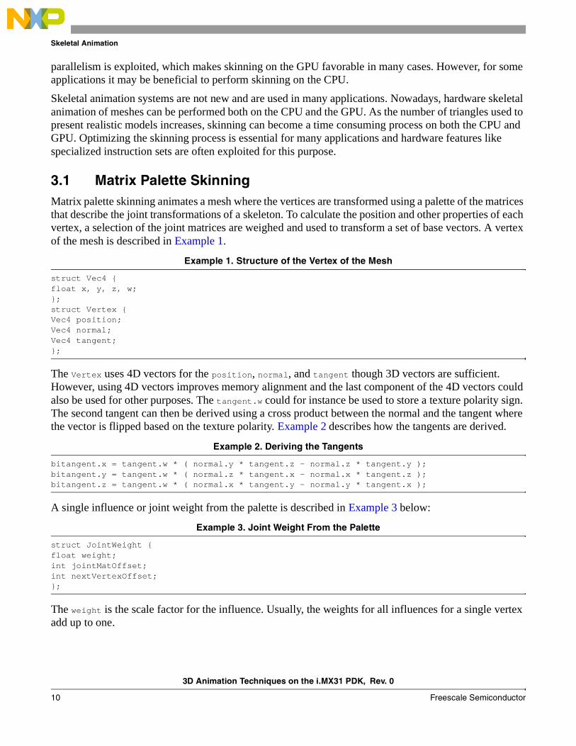
3.1 Matrix Palette SkinningMatrix palette skinning animates a mesh where the vertices are transformed using a palette of the matrices that describe the joint transformations of a skeleton. To calculate the position and other properties of each vertex, a selection of the joint matrices are weighed and used to transform a set of base vectors. A vertex of the mesh is described in Example 1.
Example 1. Structure of the Vertex of the Mesh
struct Vec4 {float x, y, z, w; }; struct Vertex { Vec4 position; Vec4 normal; Vec4 tangent; };
The Vertex uses 4D vectors for the position, normal, and tangent though 3D vectors are sufficient. However, using 4D vectors improves memory alignment and the last component of the 4D vectors could also be used for other purposes. The tangent.w could for instance be used to store a texture polarity sign. The second tangent can then be derived using a cross product between the normal and the tangent where the vector is flipped based on the texture polarity. Example 2 describes how the tangents are derived.
Example 2. Deriving the Tangents
bitangent.x = tangent.w * ( normal.y * tangent.z - normal.z * tangent.y );bitangent.y = tangent.w * ( normal.z * tangent.x - normal.x * tangent.z );bitangent.z = tangent.w * ( normal.x * tangent.y - normal.y * tangent.x );
A single influence or joint weight from the palette is described in Example 3 below:
Example 3. Joint Weight From the Palette
struct JointWeight {float weight;int jointMatOffset;int nextVertexOffset;};
The weight is the scale factor for the influence. Usually, the weights for all influences for a single vertex add up to one.
3D Animation Techniques on the i.MX31 PDK, Rev. 0
Freescale Semiconductor 11
Skeletal Animation
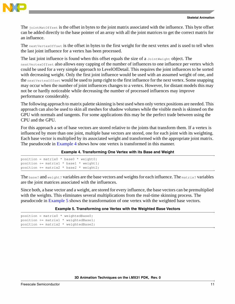
The jointMatOffset is the offset in bytes to the joint matrix associated with the influence. This byte offset can be added directly to the base pointer of an array with all the joint matrices to get the correct matrix for an influence.
The nextVertexOffset is the offset in bytes to the first weight for the next vertex and is used to tell when the last joint influence for a vertex has been processed.
The last joint influence is found when this offset equals the size of a JointWeight object. The nextVertexOffset also allows easy capping of the number of influences to one influence per vertex which could be used for a very simple approach to LevelOfDetail. This requires the joint influences to be sorted with decreasing weight. Only the first joint influence would be used with an assumed weight of one, and the nextVertexOffset would be used to jump right to the first influence for the next vertex. Some snapping may occur when the number of joint influences changes to a vertex. However, for distant models this may not be or hardly noticeable while decreasing the number of processed influences may improve performance considerably.
The following approach to matrix palette skinning is best used when only vertex positions are needed. This approach can also be used to skin all meshes for shadow volumes while the visible mesh is skinned on the GPU with normals and tangents. For some applications this may be the perfect trade between using the CPU and the GPU.
For this approach a set of base vectors are stored relative to the joints that transform them. If a vertex is influenced by more than one joint, multiple base vectors are stored, one for each joint with its weighting. Each base vector is multiplied by its associated weight and transformed with the appropriate joint matrix. The pseudocode in Example 4 shows how one vertex is transformed in this manner.
Example 4. Transforming One Vertex with its Base and Weight
position = matrix0 * base0 * weight0;position += matrix1 * base1 * weight1; position += matrix2 * base2 * weight2;
The base? and weight? variables are the base vectors and weights for each influence. The matrix? variables are the joint matrices associated with the influences.
Since both, a base vector and a weight, are stored for every influence, the base vectors can be premultiplied with the weights. This eliminates several multiplications from the real-time skinning process. The pseudocode in Example 5 shows the transformation of one vertex with the weighted base vectors.
Example 5. Transforming one Vertex with the Weighted Base Vectors
position = matrix0 * weightedBase0;position += matrix1 * weightedBase1; position += matrix2 * weightedBase2;
3D Animation Techniques on the i.MX31 PDK, Rev. 0
12 Freescale Semiconductor
Comparison of Animation Techniques
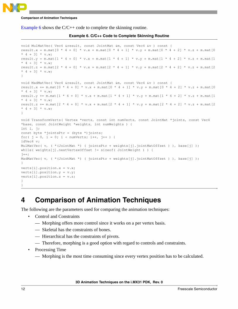
Example 6 shows the C/C++ code to complete the skinning routine.
Example 6. C/C++ Code to Complete Skinning Routine
void MulMatVec( Vec4 &result, const JointMat &m, const Vec4 &v ) const { result.x = m.mat[0 * 4 + 0] * v.x + m.mat[0 * 4 + 1] * v.y + m.mat[0 * 4 + 2] * v.z + m.mat[0 * 4 + 3] * v.w; result.y = m.mat[1 * 4 + 0] * v.x + m.mat[1 * 4 + 1] * v.y + m.mat[1 * 4 + 2] * v.z + m.mat[1 * 4 + 3] * v.w; result.z = m.mat[2 * 4 + 0] * v.x + m.mat[2 * 4 + 1] * v.y + m.mat[2 * 4 + 2] * v.z + m.mat[2 * 4 + 3] * v.w; }
void MadMatVec( Vec4 &result, const JointMat &m, const Vec4 &v ) const { result.x += m.mat[0 * 4 + 0] * v.x + m.mat[0 * 4 + 1] * v.y + m.mat[0 * 4 + 2] * v.z + m.mat[0 * 4 + 3] * v.w; result.y += m.mat[1 * 4 + 0] * v.x + m.mat[1 * 4 + 1] * v.y + m.mat[1 * 4 + 2] * v.z + m.mat[1 * 4 + 3] * v.w; result.z += m.mat[2 * 4 + 0] * v.x + m.mat[2 * 4 + 1] * v.y + m.mat[2 * 4 + 2] * v.z + m.mat[2 * 4 + 3] * v.w; }
void TransformVerts( Vertex *verts, const int numVerts, const JointMat *joints, const Vec4 *base, const JointWeight *weights, int numWeights ) { int i, j; const byte *jointsPtr = (byte *)joints; for( j = 0, i = 0; i < numVerts; i++, j++ ) { idVec4 v; MulMatVec( v, ( *(JointMat *) ( jointsPtr + weights[j].jointMatOffset ) ), base[j] ); while( weights[j].nextVertexOffset != sizeof( JointWeight ) ) { j++; MadMatVec( v, ( *(JointMat *) ( jointsPtr + weights[j].jointMatOffset ) ), base[j] ); }
verts[i].position.x = v.x; verts[i].position.y = v.y; verts[i].position.z = v.z; } }
4 Comparison of Animation TechniquesThe following are the parameters used for comparing the animation techniques:
• Control and Constraints
— Morphing offers more control since it works on a per vertex basis.
— Skeletal has the constraints of bones.
— Hierarchical has the constraints of pivots.
— Therefore, morphing is a good option with regard to controls and constraints.
• Processing Time
— Morphing is the most time consuming since every vertex position has to be calculated.

3D Animation Techniques on the i.MX31 PDK, Rev. 0
Freescale Semiconductor 13
Conclusion
— Skeletal animation can be very time consuming and difficult to process. However, it can be optimized in many ways and many times hardware support is available for this technique (not in i.MX31).
— Hierarchical animation is very efficient in terms of processing since it uses OpenGL basic operations.
— Therefore, hierarchical is a good option with regard to processing time.
• Better Looks
— Doing complex facial expressions using skeletal animation would be very odd looking. Also, coding facial expression using hierarchical animation would be very complex.
— As mentioned before, morphing is used for animation of clothes, skin, face, and non-solid bodies. This is because modeling and animating something non solid with bones is difficult and in most cases odd looking. The same thing applies to hierarchical animation.
— Skeletal animation is used for characters and highly solid objects, organic stuff or things with skin-like surface.
— Hierarchical animation may be used for things with more solid linear movement like a robot.
— Therefore, both morphing and skeletal are good options with regard to looks of an animation.
• Memory
— In terms of memory, almost always morphing takes more space because of the number of key frames that have to be stored for the animation. For example, 20 key frames are required for a model with 4,000 vertices. This means 80,000 vertices have to be stored in the program.
— Skeletal animation takes a considerable amount of memory depending on the number of bones and the weight maps. Based on this, the number of matrices and their sizes may increase.
— Hierarchical animation takes no more than a few global variables for control of the positions.
— Therefore, hierarchical is a good option with regard to memory.
• Coding Difficulty
— Hierarchical is the easiest to program as shown in the pseudocode in Section 2, “Hierarchical Animation.”
— Morphing is fairly easy to code unless the user wants to make very detailed interpolations in the vertex information.
— Skeletal is the most difficult to code and requires a more experienced programer to implement it.
— Therefore, hierarchical is a good option with regard to the level of difficulty in coding.
5 ConclusionThere is no single best animation technique. All depends on how good the animation must look and the resources available. For the best looking animation, combine skeletal and morphing animation depending on the kind of object to be animated (solid or non-solid).
Implementing skeletal and using morphing to take care of small details slows down the development of the project. Also, implementing skeletal with a few resources and no hardware support may end up being

3D Animation Techniques on the i.MX31 PDK, Rev. 0
14 Freescale Semiconductor
Revision History
too slow or even impossible to implement. A combination of morphing and less memory results in the user using less than the key frames needed. The animation may look bad or simply run out of memory.
In conclusion, use hierarchical as a low cost resource keeping in mind its limitations in looks and advantages in memory and processing. Do not use this technique if there is enough time and resources.
6 Revision HistoryTable 1 provides a revision history for this application note.
Table 1. Document Revision History
Rev.Number
Date Substantive Change(s)
0 01/2010 Initial Release

3D Animation Techniques on the i.MX31 PDK, Rev. 0
Freescale Semiconductor 15
Revision History
THIS PAGE INTENTIONALLY LEFT BLANK
Document Number: AN4044Rev. 001/2010
Information in this document is provided solely to enable system and software
implementers to use Freescale Semiconductor products. There are no express or
implied copyright licenses granted hereunder to design or fabricate any integrated
circuits or integrated circuits based on the information in this document.
Freescale Semiconductor reserves the right to make changes without further notice to
any products herein. Freescale Semiconductor makes no warranty, representation or
guarantee regarding the suitability of its products for any particular purpose, nor does
Freescale Semiconductor assume any liability arising out of the application or use of
any product or circuit, and specifically disclaims any and all liability, including without
limitation consequential or incidental damages. “Typical” parameters which may be
provided in Freescale Semiconductor data sheets and/or specifications can and do
vary in different applications and actual performance may vary over time. All operating
parameters, including “Typicals” must be validated for each customer application by
customer’s technical experts. Freescale Semiconductor does not convey any license
under its patent rights nor the rights of others. Freescale Semiconductor products are
not designed, intended, or authorized for use as components in systems intended for
surgical implant into the body, or other applications intended to support or sustain life,
or for any other application in which the failure of the Freescale Semiconductor product
could create a situation where personal injury or death may occur. Should Buyer
purchase or use Freescale Semiconductor products for any such unintended or
unauthorized application, Buyer shall indemnify and hold Freescale Semiconductor
and its officers, employees, subsidiaries, affiliates, and distributors harmless against all
claims, costs, damages, and expenses, and reasonable attorney fees arising out of,
directly or indirectly, any claim of personal injury or death associated with such
unintended or unauthorized use, even if such claim alleges that Freescale
Semiconductor was negligent regarding the design or manufacture of the part.
How to Reach Us:
Home Page: www.freescale.com
Web Support: http://www.freescale.com/support
USA/Europe or Locations Not Listed: Freescale Semiconductor, Inc.Technical Information Center, EL5162100 East Elliot Road Tempe, Arizona 85284 1-800-521-6274 or+1-480-768-2130www.freescale.com/support
Europe, Middle East, and Africa:Freescale Halbleiter Deutschland GmbHTechnical Information CenterSchatzbogen 781829 Muenchen, Germany+44 1296 380 456 (English) +46 8 52200080 (English)+49 89 92103 559 (German)+33 1 69 35 48 48 (French) www.freescale.com/support
Japan: Freescale Semiconductor Japan Ltd. HeadquartersARCO Tower 15F1-8-1, Shimo-Meguro, Meguro-ku Tokyo 153-0064Japan 0120 191014 or+81 3 5437 [email protected]
Asia/Pacific: Freescale Semiconductor China Ltd. Exchange Building 23FNo. 118 Jianguo RoadChaoyang DistrictBeijing 100022China+86 10 5879 [email protected]
For Literature Requests Only:Freescale Semiconductor
Literature Distribution Center 1-800 441-2447 or+1-303-675-2140Fax: +1-303-675-2150LDCForFreescaleSemiconductor
@hibbertgroup.com
Freescale and the Freescale logo are trademarks or registered trademarks of Freescale Semiconductor, Inc. in the U.S. and other countries. All other product or service names are the property of their respective owners. ARM is the registered trademark of ARM Limited. ARMnnn is the trademark of ARM Limited.
© Freescale Semiconductor, Inc., 2010. All rights reserved.