3d design & simulation of a z shape antenna with a cpw tx line
DESCRIPTION
This paper presents design of à new Z shaped antenna with a cpw (coplanar waveguide)transmission line. In this proposed research paper, the impedance increases with a pair of Z shape combineddesign on the FR-4 substrate and ground plane. The main features of the Z antenna are the compactdimensions and band-operating characteristics that are obtained without modifying the radiator or theground plane. The antenna consists of a l inear patch as radiator, a partial CPW-ground plane, and aslotted conductor-backed plane. Impedance matching for dual-band operations is achieved by a pair of mirrorsquare-shaped slots at the conductor-backed plane. This antenna size is very compact with 28.8 mm × 37.2 mm× 1.6 mm and covers 1.696 GHz to 2.646 GHz and can be used for GSM and WLAN applications. Ourdesigning aim is to describe radiation pattern both 3D and normal and discuss obtained gainTRANSCRIPT
American Journal of Engineering Research (AJER) 2015
American Journal of Engineering Research (AJER)
e-ISSN: 2320-0847 p-ISSN : 2320-0936
Volume-4, Issue-7, pp-68-72
www.ajer.org Research Paper Open Access
w w w . a j e r . o r g
Page 68
3D Design & Simulation of a Z Shape Antenna with a CPW Tx
Line
Protap Mollick1, Amitabh Halder
2, Mohammad Forhad Hossai ,
A S M Wasi
1(CSE, American International University-Bangladesh, Bangladesh)
2(EEE, American International University-Bangladesh, Bangladesh)
3(EEE, American International University-Bangladesh, Bangladesh)
4(MSc in IT, Central Queensland University, Australia)
ABSTRACT : This paper presents design of à new Z shaped antenna with a cpw (coplanar waveguide)
transmission line. In this proposed research paper, the impedance increases with a pair of Z shape combined
design on the FR-4 substrate and ground plane. The main features of the Z antenna are the compact
dimensions and band-operating characteristics that are obtained without modifying the radiator or the
ground plane. The antenna consists of a linear patch as radiator, a partial CPW-ground plane, and a
slotted conductor-backed plane. Impedance matching for dual-band operations is achieved by a pair of mirror
square-shaped slots at the conductor-backed plane. This antenna size is very compact with 28.8 mm × 37.2 mm
× 1.6 mm and covers 1.696 GHz to 2.646 GHz and can be used for GSM and WLAN applications. Our
designing aim is to describe radiation pattern both 3D and normal and discuss obtained gain. KEYWORDS – Microstrip, Coplanar waveguide, Impedance, HFSS, Bandwidth.
I. INTRODUCTION In recent years demand for small antennas on wireless communication has increased the interest of
research work on compact microstrip various kind of shaped antenna design among microwaves and wireless
technology. To support the high mobility necessity for a wireless telecommunication device, a small and light
weight Z shape antenna is likely to be preferred. For this purpose compact Z shaped antenna is one of the most
suitable applications. The development of Z shaped antenna for wireless communication also requires an
antenna with more than one operating frequencies. This is due to many reasons, mainly because there are
various wireless communication systems and many telecommunication operators using various frequencies.
However, the general Z shaped patch antennas have some disadvantages such as narrow bandwidth etc.
Enhancement of the performance to cover the demanding bandwidth is necessary [1]. But overhead those
drawbacks Z shaped antenna is now most popular antenna. In the design of a Z shape antenna with a coplanar
waveguide, the shape of the Z antenna patch, the ground plane, and the geometry of the ground plane slots are
of great importance. Proposed Z shaped have included rectangular ones. Different methods, such as the
truncated slot on the antenna patch, have been pro-posed for increasing impedance bandwidth .Recently, some
coplanar waveguide (CPW) Z antennas have been reported. In most reported antennas, up to now, the slots have
been used for improving the lower frequency of the band and enhancing the upper frequency of the band. In this
paper, a novel CPW-fed Z antenna without slot on the patch or ground plane is proposed with a Z-shaped form.
In this antenna, using a pair of Z-shape combined (ESC) design on the patch, a proper control on the upper and
lower frequencies of the band can be achieved. In addition, on the ground plane, a pair of ESC form is located
for improving impedance matching and optimizing gain [2]. Coplanar waveguide is a type of electrical
transmission line which can be fabricated using printed circuit board technology, and is used to convey
microwave-frequency signals. On a smaller scale, coplanar waveguide transmission lines are also built into
monolithic microwave integrated circuits. Conventional coplanar waveguide (CPW) consists of a single
conducting track printed onto a dielectric substrate, together with a pair of return conductors, one to either side
of the track. All three conductors are on the same side of the substrate, and hence are coplanar. The return
conductors are separated from the central track by a small gap, which has an unvarying width along the length
of the line. Away from the central conductor, the return conductors usually extend to an indefinite but large
distance, so that each is notionally a semi-infinite plane.
American Journal of Engineering Research (AJER) 2015
w w w . a j e r . o r g
Page 69
The advantages of coplanar waveguide are that active devices can be mounted on top of the circuit, like
on microstrip. More importantly, it can provide extremely high frequency response since connecting to coplanar
waveguide does not entail any parasitic discontinuities in the ground plane. One disadvantage is potentially
lousy heat dissipation. However, the main reason that coplanar waveguide is not used is that there is a general
lack of understanding of how to employ it within the microwave design community.
II. DESIGN AND EQUATIONS The dielectric constant of the substrate is closely related to the size and the bandwidth of the Z shape
antenna. Low dielectric constant of the substrate produces larger bandwidth. The resonant frequency of Z shape
antenna and the size of the radiation patch can be similar to the following formulas while the high dielectric
constant of the substrate results in smaller size of antenna [3].
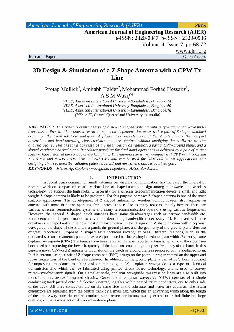
Figure 1: Z shape antenna
Figure 1 shows the geometry of the design of Z shape with a coplanar waveguide transmission line in
which the Length of ground plane of Antenna is 38.4 mm and Width is 46.8 mm, L & W of the patch is 28.8
mm & 37.2 mm.
The patch width, effective dielectric constant, the length extension and also patch length are given by
where c is the velocity of light, e is the dielectric content of substrate, f is the antenna working frequency, W is
the patch non resonant width, and the effective dielectric constant is e given as,
The extension length ∆ is calculates as,
By using above equation we can find the value of actual length of the patch as,
III. SIMULATION RESULTS AND TABLE The antenna simulation pattern is a measure of its power or radiation distribution with respect to a
particular type of coordinates. We generally consider spherical coordinates as the ideal antenna is supposed to
radiate in a spherically symmetrical pattern [4]. However antennae in practice are not Omni directional but
have a radiation maximum along one particular direction. Z shape antenna is a broadside antenna wherein the
maximum radiation occurs along the axis of the antenna [5].
American Journal of Engineering Research (AJER) 2015
w w w . a j e r . o r g
Page 70
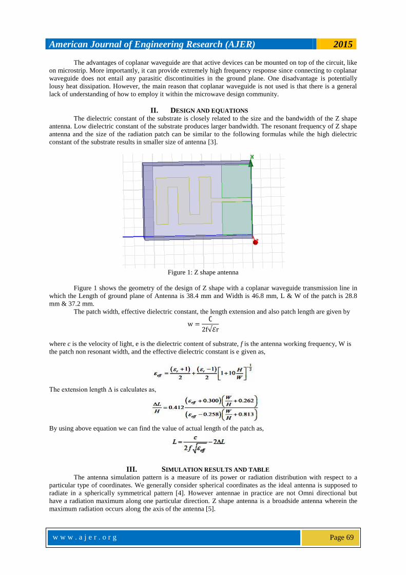
Figure 2: Graph of Return loss.
In Figure 2 presents the graph of the return loss. It is clearly shown that lowest return loss is found at 1.60 GHz.
And highest return loss found at 1 GHz frequency. Overall average return loss is not very effective.
Figure 3: Frequency Vs Imaginary Impedance Graph.
In figure 3 describe the Impedance graph. There are two lines. One of them the upper one represents Imaginary
Impedance graph and other one presents Real Impedance graph. We got Imaginary values are the highest in
every frequency rather than real impedance graph. When frequency is 1.70 GHz found the highest impedance
values for both graph.
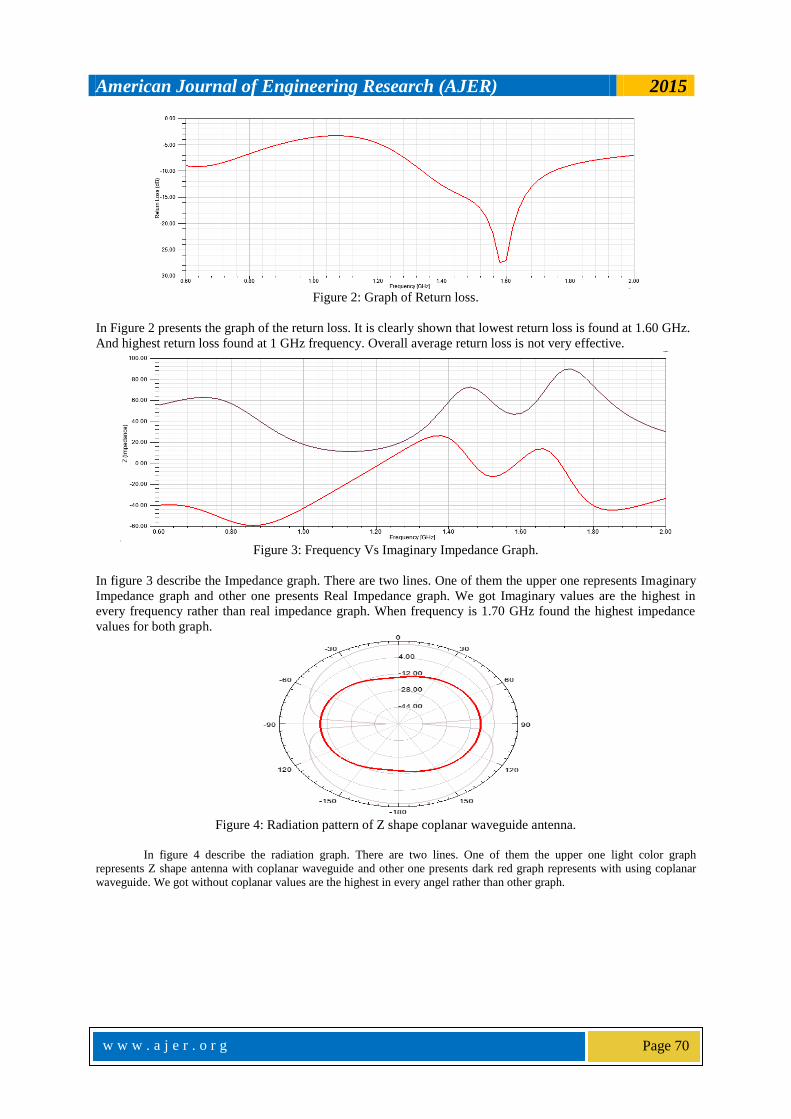
Figure 4: Radiation pattern of Z shape coplanar waveguide antenna.
In figure 4 describe the radiation graph. There are two lines. One of them the upper one light color graph
represents Z shape antenna with coplanar waveguide and other one presents dark red graph represents with using coplanar
waveguide. We got without coplanar values are the highest in every angel rather than other graph.

American Journal of Engineering Research (AJER) 2015
w w w . a j e r . o r g
Page 71
Figure 5: 3D pattern of Z shape antenna.
Figure 5 presents basic 3d pattern of Z shape antenna with using coplanar waveguide transmission line.
We found at least 73 values from our simulation here we submit 14 values as a sample.it is clearly
shown that it follow per 90 degree cycle that means per 90 degree its values at the nadir point and after that
complete 90 degree it is in crest point.
IV. CONCLUSION This thesis detailed the various aspects associated with the modelling of Z shape antenna with coplanar
guide transmission line. One of the goal was introduction of HFSS as a simulation tool for electromagnetic
analysis. An effort was understanding of the design process in HFSS, which aid the reader in building any
simulation in HFSS [6]. In this paper a compact size Z shaped antenna has been designed having good
impedance matching as well as high antenna; efficiency of about 95% is achieved. The proposed antenna has
larger impedance bandwidth of 43.578% covering the frequency range from 1.696 GHz to 2.646 GHz which is
suitable for PCS-1900, GSM and WLAN (802.11b) applications. Obviously there are some limitations of Z
shape antenna some of them are listed below:
Its effective dielectric constant is lower.
Layout is very compact.
Shunt element is quite low.
V. ACKNOWLEDGEMENTS We are earnestly grateful to one our group member, Protap Mollick, Graduated, Department of CSE,
American International University-Bangladesh. For providing us with his special advice and guidance for this
project. Finally, we express our heartiest gratefulness to the Almighty and our parents who have courageous
throughout our work of the project.

American Journal of Engineering Research (AJER) 2015
w w w . a j e r . o r g
Page 72
REFERENCES [1] X. F. Shi, Z. H. Wang, H. Su and Y. Zhao, “A H-Type CPW Slot Antenna in Ku-band Using LTCC Technology with Multiple Layer
Substrates,” Second International Conference on Mechanic Automation and Control Engineering (MACE), Hohhot, 15-17 July 2011,
pp.7104-7106.
[2] U. Chakraborty, S. Chatterjee, S. K. Chowdhury and P. Sarkar, “A Compact Z shape Patch Antenna for Wireless Communication, “Progress in Electromagnetics Research C, Vol.18, 2011, pp.211-220.
[3] H. Sabri and Z. Atlasbaf, “Two Novel Compact Triple Band CPW Annular-Ring Slot Antenna for PCS-1900 and WLAN
Applications,” Progress in Electromagnetics Research Letters, Vol. 5, 2008, pp. 87-98. http://dx.doi.org/10.2528/PIERL08110301 [4] K. Kumar and N. Gunasekaran, “A Novel Wideband Slotted mm Wave Micro strip Patch Antenna,” International Conference on
Signal Processing, Communication, Computing and Networking Technologies (ICSCCN), Thackeray, 21-22 July 2011, pp. 10-14.
[5] D. Xi, L. H. Wen, Y. Z. Yin, Z. Zhang and Y. N. Mo, “A Compact Dual Inverted C Shaped Slots Antenna for WLAN Application,” Progress in Electromagnetics Research Letters,Vol.17,2010,pp.115-123.
[6] G. M. Zhang, J. S. Hong and B. Z. Wang, “Two Novel Band-Notched UWB Slot Antennas Fed by Z shape Line,” Progress in
Electromagnetics Research, Vol. 78, 2008, pp. 209-218. http://dx.doi.org/10.2528/PIER07091201