3d face reconstruction with geometry details from … 3d face reconstruction with geometry details...
TRANSCRIPT

SUBMITTED TO IEEE TRANSACTIONS ON IMAGE PROCESSING 1
3D Face Reconstruction with Geometry Detailsfrom a Single Image
Luo Jiang, Juyong Zhang†, Bailin Deng, Member, IEEE, Hao Li, and Ligang Liu, Member, IEEE,
Abstract—3D face reconstruction from a single image is aclassical and challenging problem, with wide applications in manyareas. Inspired by recent works in face animation from RGB-D or monocular video inputs, we develop a novel method forreconstructing 3D faces from unconstrained 2D images, using acoarse-to-fine optimization strategy. First, a smooth coarse 3Dface is generated from an example-based bilinear face model, byaligning the projection of 3D face landmarks with 2D landmarksdetected from the input image. Afterwards, using local correctivedeformation fields, the coarse 3D face is refined using photometricconsistency constraints, resulting in a medium face shape. Finally,a shape-from-shading method is applied on the medium face torecover fine geometric details. Our method outperforms state-of-the-art approaches in terms of accuracy and detail recovery,which is demonstrated in extensive experiments using real worldmodels and publicly available datasets.
Index Terms—Tensor Model, Shape-from-shading, 3D FaceReconstruction.
I. INTRODUCTION
Reconstruction of 3D face models using 2D images is afundamental problem in computer vision and graphics [1],with various applications such as face recognition [2], [3]and animation [4], [5]. However, this problem is particularlychallenging, due to the loss of information during cameraprojection.
In the past, a number of methods have been proposed for faceconstruction using a single image. Among them, example-basedmethods first build a low-dimensional parametric representationof 3D face models from an example set, and then fit the paramet-ric model to the input 2D image. One of the most well-knownexamples is the 3D Morphable Model (3DMM) proposed byBlanz and Vetter [6], represented as linear combination of theexample faces. 3DMM is a popular parametric face modeldue to its simplicity, and has been the foundation of othermore sophisticated face reconstruction methods [3]. Anotherapproach to single image reconstruction is to solve it as Shape-from-shading (SFS) [7], a classical computer vision problemof 3D shape recovery from shading variation. For example,Kemelmacher-Shlizerman and Basri [8] reconstruct the depthinformation from an input face image, by estimating its lightingand reflectance parameters using a reference face shape.
While these existing approaches are able to produce high-quality reconstruction from a single image, they also come
L. Jiang, J. Zhang, H. Li, and L. Liu are with School of MathematicalSciences, University of Science and Technology of China.
B. Deng is with School of Computer Science and Informatics, CardiffUniversity.†Corresponding author. Email: [email protected].
Figure 1: 3D face reconstruction from a single image. Given aninput image (left), we reconstruct a 3D face with fine geometricdetails (right, top row). The input image can be used as texturefor rendering the reconstructed face (right, bottom row).
with limitations. Although example-based methods are simpleand efficient, they rely heavily on the dataset, and may produceunsatisfactory results when the target face is largely differentfrom those in the example set; moreover, due to the limited de-grees of freedom of the low-dimensional model, these methodsoften fail to reproduce fine geometric details (such as wrinkles)that are specific to the target face. SFS-based methods are ableto capture the fine-scale facial details from the appearance ofthe input image; however, they require prior knowledge aboutthe geometry or illumination to resolve the ambiguity of thereconstruction problem, and may become inaccurate when theinput image does not satisfy the assumptions.
In this paper, we propose a novel coarse-to-fine method toreconstruct a high-quality 3D face model from a single image.Our method consists of three steps:
• First, we compute a coarse estimation of the target3D face, by fitting an example-based parametric facemodel to the input image. Our parametric model isderived from FACEWAREHOUSE [9] and the Basel FaceModel (BFM2009) [10], two 3D face datasets with largevariation in expression and identity respectively. Theresulting mesh model captures the overall shape of thetarget face.
• Afterwards, we enhance the coarse face model by applyingsmooth deformation that captures medium-scale facialfeatures; we also estimate the lighting and reflectanceparameters from the enhanced face model.
arX
iv:1
702.
0561
9v2
[cs
.CV
] 1
1 Ju
n 20
18

SUBMITTED TO IEEE TRANSACTIONS ON IMAGE PROCESSING 2
Coarse Medium
......
Input
Output
corrections
landmarks
face model SFS
Figure 2: An overview of our coarse-to-fine face reconstruction approach.
• Finally, the illumination parameters and the enhanced facemodel are utilized to compute a height-field face surfaceaccording to the shading variation of the input image. Thisfinal model faithfully captures the fine geometric detailsof the target face (see Fig. 1).
Our method builds upon the strength of the existing ap-proaches mentioned above: the example-based coarse faceenables more reliable estimation of illumination parameters, andimproves the robustness of the final SFS step; the SFS-basedfinal face model provides detailed geometric features, whichare often not available from example-based approaches. Ourmethod outperforms existing example-based and SFS methodsin terms of reconstruction accuracy as well as geometric detailrecovery, as shown by extensive experimental results usingpublicly available datasets.
II. RELATED WORK
Low-dimensional models. Human faces have similar globalcharacteristics, for example the location of main facial featuressuch as eyes, nose and mouth. From a perception perspective, ithas been shown that a face can be characterized using a limitednumber of parameters [11], [12]. The low dimensionality of theface space allows for effective parametric face representationsthat are derived from a collection of sample faces, reducingthe reconstruction problem into searching within the parameterspace. A well-known example of such representations is the3DMM proposed in [6], which has been used for various faceprocessing tasks such as reconstruction [6], [13], [14], [15],[16], recognition [2], [3], face exchange in images [17], andmakeup suggestion [18]. Low-dimensional representations havealso been used for dynamic face processing. To transfer facialperformance between individuals in different videos, Vlasicet al. [19] develop a multilinear face model representationthat separately parameterizes different face attributes such asidentity, expression, and viseme. In the computer graphicsindustry, facial animation is often achieved using linear modelscalled blendshapes, where individual facial expressions arecombined to create realistic facial movements [20]. Thesimplicity and efficiency of blendshapes models enable real-time facial animation driven by facial performance capturedfrom RGBD cameras [21], [22], [23], [24], [25] and monocular
videos [26], [4], [27], [5]. When using low-dimensional facerepresentations derived from example face shapes, the exampledataset has strong influence on the resulting face models. Forinstance, it would be difficult to reconstruct a facial expressionthat deviates significantly from the sample facial expressions. Inthe past, during the development of face recognition algorithms,various face databases have been collected and made publiclyavailable [28]. Among them, BFM2009 provides 3DMMrepresentation for a large variety of facial identities. Recently,Cao et al. [9] introduced FACEWAREHOUSE, a 3D facialexpression database that provides the facial geometry of 150subjects, covering a wide range of ages and ethnic backgrounds.Our coarse face modeling method adopts a bilinear face modelthat encodes identity and expression attributes in a way similarto [19]. We use FACEWAREHOUSE and BFM2009 as theexample dataset, due to the variety of facial expressions andidentities that they provide respectively.
Shape-from-shading. Shape-from-shading (SFS) [7], [29]is a computer vision technique that recovers 3D shapes fromtheir shading variation in 2D images. Given the informationabout illumination, camera projection, and surface reflectance,SFS methods are able to recover fine geometric details thatmay not be available using low-dimensional models. On theother hand, SFS is an ill-posed problem with potentiallyambiguous solutions [30]. Thus for face reconstruction, priorknowledge about facial geometry must be incorporated toachieve reliable results. For example, symmetry of humanfaces has been used by various authors to reduce the ambiguityof SFS results [31], [32], [33]. Another approach is to solvethe SFS problem within a human face space, using a low-dimensional face representation [34], [35]. Other approachesimprove the robustness of SFS by introducing an extra datasource, such as a separate reference face [8], as well ascoarse reconstructions using multiview stereo [36], [37] orunconstrained photo collections [38], [39], [40]. We adopt asimilar approach which builds an initial estimation of the faceshape and augment it with fine geometric details using SFS.Our initial face estimation combines coarse reconstruction in alow-dimensional face space with refinement of medium-scalegeometric features, providing a more accurate initial shape forsubsequent SFS processing.

SUBMITTED TO IEEE TRANSACTIONS ON IMAGE PROCESSING 3
III. OVERVIEW
This section provides an overview of our coarse-to-fineapproach to reconstructing a high-quality 3D face model from asingle photograph. Fig. 2 illustrates the pipeline of our method.
To create a coarse face model (Sec. IV), we first builda bilinear model from FACEWAREHOUSE and BFM2009 todescribe a plausible space of 3D faces; the coarse face shape isgenerated from the bilinear model by aligning the projection ofits 3D landmarks with the 2D landmarks detected on the inputimage, using a fitting energy that jointly optimizes the shapeparameters (e.g., identity, expression) and camera parameters.To further capture person-specific features that are not availablefrom the bilinear model, we enhance the coarse face usingan additional deformation field that corresponds to medium-scale geometric features (Sec. V); the deformation field isjointly optimized with the lighting and albedo parameters,such that the shading of the enhanced model is close to theinput image. Afterwards, the resulting medium face model isaugmented with fine geometric details (Sec. VI): the normalfield from the medium face model is modified according to theinput image gradients as well as the illumination parametersderived previously, and the modified normal field is integratedto achieve the final face shape.
IV. COARSE FACE MODELING
Preprocessing. The FACEWAREHOUSE dataset containshead meshes of 150 individuals, each with 47 expressions. Allexpressions are represented as meshes with the same connectiv-ity, each consisting of 11510 vertices. The BFM2009 datasetcontains 200 face meshes, and each mesh consists of 53490vertices. In order to combine the two datasets, we first maskthe face region on the head mesh from FACEWAREHOUSE toextract a face mesh, and fill the holes in the regions of eyes andmouth, to obtain a simply connected face mesh consisting of5334 vertices. Afterwards, we randomly sample the parameterspace for BFM2009 to generate 150 neutral face models,and deform the average face model from FACEWAREHOUSEto fit these models via nonrigid registration [41]. Then wetransfer the other 46 expressions of the FACEWAREHOUSEaverage face model to each of the 150 deformed face modelsbased on the method in [41]. In this way, we construct anew dataset containing 300 individuals (150 from BFM2009and 150 from FACEWAREHOUSE), each with 47 expressions.We perform Procrustes alignment for all the face meshesin the dataset. Moreover, BFM2009 provides 199 principalcomponents to span the surface albedo space, but these principalalbedo components cannot be used for our new dataset directlydue to different mesh connectivity. Thus we transfer theiralbedo information to the new mesh representation usingthe correspondence identified in the nonrigid registration, toconstruct 199 principal albedo components for our dataset.These principal components will be used in Sec V.
Bilinear face model. Following [19], we collect the vertexcoordinates of all face meshes into a third-order data tensor,and perform 2-mode SVD reduction along the identity modeand the expression mode, to derive a bilinear face model thatapproximates the original data set. In detail, the bilinear face
Figure 3: Our coarse face reconstruction is based on aligningthe projection of labeled 3D face landmarks (right) with 2Dlandmarks detected on the input image (left).
model is represented as a mesh with the same connectivity asthose from the data set, and its vertex coordinates F ∈ R3×Nv
are computed as
F = Cr ×2 wTid ×3 wT
exp, (1)
where Nv is the number of vertices, Cr is the reducedcore tensor computed from the SVD reduction, and wid ∈R100,wexp ∈ R47 are column vectors for the identity weightsand expression weights which control the face shape. Note thathere we only reduce the dimension along the identity mode,in order to maintain the variety of facial expressions in thebilinear model. For more details on multilinear algebra, thereader is referred to [42].
To construct a coarse face, we align 3D landmarks on thebilinear face model with corresponding 2D landmarks fromthe input image. First, we preprocess the bilinear face mesh tomanually label 68 landmark vertices. Given an input image, wedetect the face as well as its corresponding 68 landmarks usingthe method in [43] (see Fig. 3 for an example). Assumingthat the camera model is a weak perspective projection alongthe Z direction, we can write the projection matrix as Π =[α 0 00 α 0
]. Then we can formulate the following fitting energy
to align the projection of landmark vertices with the detected2D landmarks
Efit =
68∑k=1
‖ΠRFvk + t−Uk‖22
+ γ1
100∑i=1
(w
(i)id
δ(i)id
)2
+ γ2
47∑j=1
(w
(j)exp
δ(j)exp
)2
. (2)
Here Fvk ∈ R3 and Uk ∈ R2 are the coordinates of the k-th3D landmark vertex and the corresponding image landmark,respectively; translation vector t ∈ R2 and rotation matrixR ∈ R3×3 determine the position and pose of the face meshwith respect to the camera; w(i)
id and w(j)exp are components
of weight vectors wid and wexp, while δ(i)id and δ(j)exp are the
corresponding singular values obtained from the 2-mode SVDreduction; γ1 and γ2 are positive weights. As in [6], the last twoterms ensure parameters w(i)
id and w(j)exp have a reasonable range
of variation. This fitting energy is minimized with respect to theshape parameters wid,wexp and the camera parameters Π,R, t
SUBMITTED TO IEEE TRANSACTIONS ON IMAGE PROCESSING 4
(a)
(c)
(b)
(d)
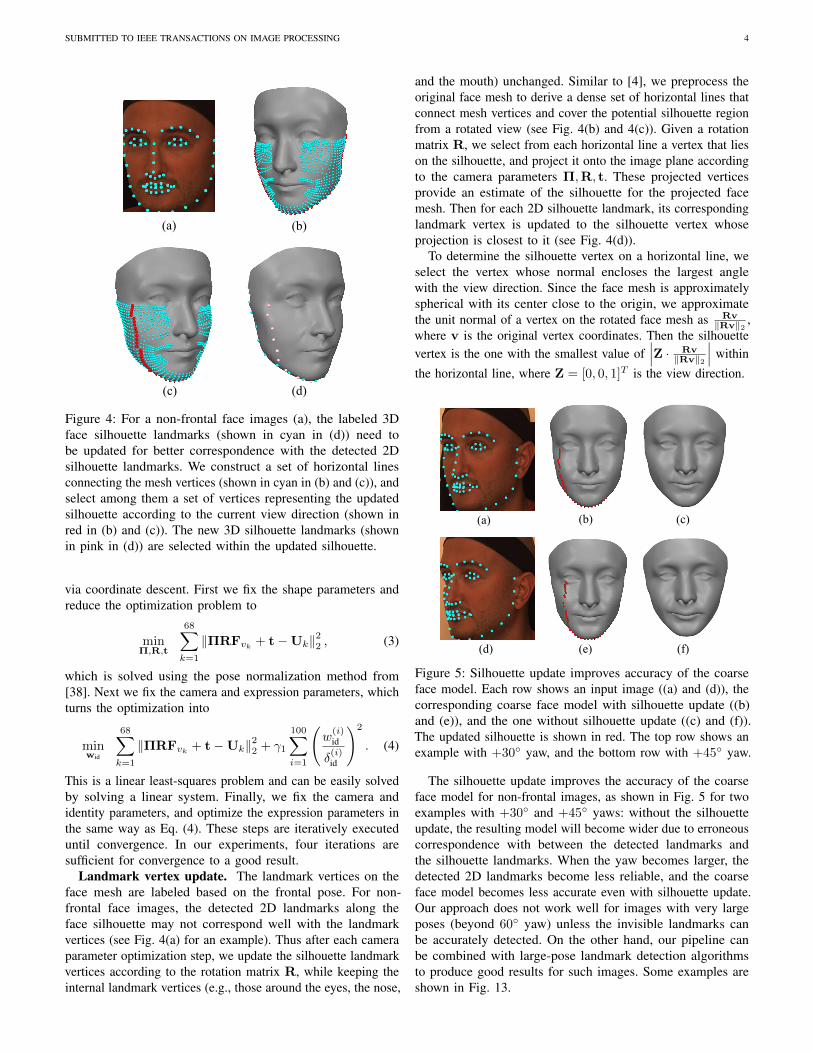
Figure 4: For a non-frontal face images (a), the labeled 3Dface silhouette landmarks (shown in cyan in (d)) need tobe updated for better correspondence with the detected 2Dsilhouette landmarks. We construct a set of horizontal linesconnecting the mesh vertices (shown in cyan in (b) and (c)), andselect among them a set of vertices representing the updatedsilhouette according to the current view direction (shown inred in (b) and (c)). The new 3D silhouette landmarks (shownin pink in (d)) are selected within the updated silhouette.
via coordinate descent. First we fix the shape parameters andreduce the optimization problem to
minΠ,R,t
68∑k=1
‖ΠRFvk + t−Uk‖22 , (3)
which is solved using the pose normalization method from[38]. Next we fix the camera and expression parameters, whichturns the optimization into
minwid
68∑k=1
‖ΠRFvk+ t−Uk‖22 + γ1
100∑i=1
(w
(i)id
δ(i)id
)2
. (4)
This is a linear least-squares problem and can be easily solvedby solving a linear system. Finally, we fix the camera andidentity parameters, and optimize the expression parameters inthe same way as Eq. (4). These steps are iteratively executeduntil convergence. In our experiments, four iterations aresufficient for convergence to a good result.
Landmark vertex update. The landmark vertices on theface mesh are labeled based on the frontal pose. For non-frontal face images, the detected 2D landmarks along theface silhouette may not correspond well with the landmarkvertices (see Fig. 4(a) for an example). Thus after each cameraparameter optimization step, we update the silhouette landmarkvertices according to the rotation matrix R, while keeping theinternal landmark vertices (e.g., those around the eyes, the nose,
and the mouth) unchanged. Similar to [4], we preprocess theoriginal face mesh to derive a dense set of horizontal lines thatconnect mesh vertices and cover the potential silhouette regionfrom a rotated view (see Fig. 4(b) and 4(c)). Given a rotationmatrix R, we select from each horizontal line a vertex that lieson the silhouette, and project it onto the image plane accordingto the camera parameters Π,R, t. These projected verticesprovide an estimate of the silhouette for the projected facemesh. Then for each 2D silhouette landmark, its correspondinglandmark vertex is updated to the silhouette vertex whoseprojection is closest to it (see Fig. 4(d)).
To determine the silhouette vertex on a horizontal line, weselect the vertex whose normal encloses the largest anglewith the view direction. Since the face mesh is approximatelyspherical with its center close to the origin, we approximatethe unit normal of a vertex on the rotated face mesh as Rv
‖Rv‖2 ,where v is the original vertex coordinates. Then the silhouettevertex is the one with the smallest value of
∣∣∣Z · Rv‖Rv‖2
∣∣∣ withinthe horizontal line, where Z = [0, 0, 1]T is the view direction.
(f)
(c)(a)
(d) (e)
(b)
Figure 5: Silhouette update improves accuracy of the coarseface model. Each row shows an input image ((a) and (d)), thecorresponding coarse face model with silhouette update ((b)and (e)), and the one without silhouette update ((c) and (f)).The updated silhouette is shown in red. The top row shows anexample with +30 yaw, and the bottom row with +45 yaw.
The silhouette update improves the accuracy of the coarseface model for non-frontal images, as shown in Fig. 5 for twoexamples with +30 and +45 yaws: without the silhouetteupdate, the resulting model will become wider due to erroneouscorrespondence with between the detected landmarks andthe silhouette landmarks. When the yaw becomes larger, thedetected 2D landmarks become less reliable, and the coarseface model becomes less accurate even with silhouette update.Our approach does not work well for images with very largeposes (beyond 60 yaw) unless the invisible landmarks canbe accurately detected. On the other hand, our pipeline canbe combined with large-pose landmark detection algorithmsto produce good results for such images. Some examples areshown in Fig. 13.

SUBMITTED TO IEEE TRANSACTIONS ON IMAGE PROCESSING 5
V. MEDIUM FACE MODELING
Although the coarse face model provides a good estimateof the overall shape, it may not capture some person-specificgeometric details due to limited variation of the constructeddata set (see Fig. 7). Thus we enhance the coarse face usingsmooth deformation that correspond to medium-scale geometricfeatures, to improve the consistency between its shading andthe input image. During this process we also estimate thelighting and the albedo. The enhanced face model and thelighting/albedo information will provide the prior knowledgerequired by the SFS reconstruction in the next section. In thispaper, we convert color input images into grayscale ones forsimplicity and efficiency. However, it is not difficult to extendthe formulation to directly process color images.
Lighting and albedo estimation. To compute shading forour face mesh, we need the information about lighting andsurface reflectance. Assuming Lambertian reflectance, we canapproximate the grayscale level si,j at a pixel (i, j) usingsecond-order spherical harmonics [44]:
si,j = ri,j ·max(ξTH(ni,j), 0). (5)
Here ri,j is the albedo at the pixel; ni,j is the correspondingmesh normal, computed via
ni,j =(vi,j
2 − vi,j1 )× (vi,j
3 − vi,j1 )
‖(vi,j2 − vi,j
1 )× (vi,j3 − vi,j
1 )‖2, (6)
where vi,j1 ,vi,j
2 ,vi,j3 are the vertex coordinates for the mesh
triangle that corresponds to pixel (i, j); H is a vector of second-order spherical harmonics
H(n) = [1, nx, ny, nz, nxny, nxnz, nynz, n2x−n2y, 3n2z−1]T ,
(7)and ξ is a vector of harmonics coefficients. For more robust es-timation, we follow [6] and parametrize the surface reflectanceusing a Principal Component Analysis (PCA) model:
ri,j =
(Φ0 +
Nr∑l=1
wlrΦl
)· ci,j , (8)
where [c1i,j , c2i,j , c
3i,j ] ∈ R3 is the barycentric coordinate
of the triangle corresponding to ri,j , [Φ0,Φ1, ...,ΦNr] ∈
RNv×(Nr+1) is a basis of vertex albedos with Nv being thenumber of vertices of the face mesh, wr = (w1
r , ..., wNrr ) ∈
RNr is a vector for the albedo weights; ci,j ∈ RNv is a vectorwhose components for the three vertices of the triangle thatcontains pixel (i, j) are equal to the barycentric coordinatesof the pixel within the triangle, and the components for othervertices are zero. Among the 199 principal albedo componentsderived from BFM2009, we choose Nr principal componentswith the largest variance as Φ1, ...,ΦNr
. We set Nr = 100 inour experiments. The lighting and albedo are then estimatedby solving an optimization problem
minr,ξ,d
∑i,j
(ri,jξ
TH(ni,j)− Ii,j)2
+ µ1
Nr∑l=1
∥∥∥∥ wlr
δ(l)r
∥∥∥∥22
,(9)
where vectors r,d collect the values ri,j, di,j, respectively;Ii,j denotes the grayscale value at pixel (i, j) of the input
. . .
+1
-1
Figure 6: Some Laplacian eigenfunctions of local regions onthe face mesh (displayed via color coding).
image; δ(l)r are the standard deviations corresponding to theprincipal directions; µ1 is a user-specified positive weight. Tooptimize this problem, we first set wr to zero and optimizethe harmonics coefficients ξ. Then we optimize the reflectanceweights wr while fixing ξ. Both sub-problems reduce to solvinga linear system. This process is iterated three times in ourexperiment.
Facial detail enhancement. With an estimate of lightingand albedo, we can now enhance the coarse face mesh to reducethe discrepancy between the mesh shading and the input image.We apply a smooth 3D deformation field to the Nv vertices ofthe frontal face mesh to minimize the following discrepancymeasure with respect to the vertex displacements D ∈ R3×Nv :
Eshading(D) =∑i,j
(ri,j max(ξTH(ni,j), 0)− Ii,j
)2, (10)
where ni,j are the new mesh face normals. Specifically,since our final goal is to recover a depth field defined on thefacial pixels in the given image, we sum over the pixels inEq. (10). The correspondence between pixels and triangles arecomputed by the Z-buffer method [45]. However, this nonlinearleast-squares problem can be very time-consuming to solve,due to the high resolution of the mesh. Therefore, we constructa low-dimensional subspace of smooth mesh deformations andsolve the optimization problem within this subspace, whichsignificantly reduces the number of variables. Specifically, ifwe measure the smoothness of a deformation field using thenorm of its graph Laplacian with respect to the mesh, thenthe Laplacian eigenfunctions associated with small eigenvaluesspan a subspace of smooth deformations. Indeed, it is wellknown in 3D geometry processing that the Laplacian eigen-values can be seen as the frequencies for the eigenfunctions,which indicate how rapidly each eigenfunction oscillates acrossthe surface [46]. Thus by restricting the deformation to thesubspace with small eigenvalues, we inhibit the enhancementof fine-scale geometric features, leaving them to the SFSreconstruction step in Sec VI. Since most facial variations arelocal, we select some local regions on the mesh, and performLaplacian eigenanalysis on each region separately (see Fig. 6).The selected eigenfunctions are then combined to span a spaceof facial variations. Specifically, for the i-th selected region,we preprocess the frontal face mesh to construct its graphLaplacian matrix Ki ∈ RNv×Nv based on mesh connectivity,and add a large positive value to the j-th diagonal elementif vertex j is outside the selected region. Then we performeigendecomposition to obtain k+1 eigenvectors ei
0, ei1, . . . , e
ik
corresponding to the smallest eigenvalues λi0 ≤ λi1 ≤ . . . ≤ λik.Among them, ei
0 has a constant value inside the selected region,

SUBMITTED TO IEEE TRANSACTIONS ON IMAGE PROCESSING 6
2.067
fine face withmedium face
0
12mm
2.338gt 2.188
coarse face
2.182
medium face
2.185
fine face withoutmedium face
2.426
coarse face witha dierent identity
fine face from medium face with a dierent identity Input image
Figure 7: Quantitative results on the dataset [47]. The input image and its ground truth shape are shown in the first column.In the other columns, we show different face reconstructions and their corresponding error maps (according to Eq. (24)): thecoarse face model, the medium face model, the fine reconstruction with and without medium face modeling, the coarse modelwith modified identity parameters, and the fine reconstruction with medium face modeling from the modified coarse face. In thebottom, we show the reconstruction error values.
representing a translation of the whole region [46]. Since itdoes not represent variation within the region, we discardei0 to get k eigenvectors Ei = [ei
1, . . . , eik]. Combing all the
eigenvectors to span the x-, y-, and z-coordinates of the vertexdisplacement vectors, we represent the deformation field as
D = (Eη)T , (11)
where E = [E1, . . . ,ENe ] ∈ RNv×(k·Ne) stacks the basis vec-tors, and η = [λ11, . . . , λ
1k, . . . , λ
Ne1 , . . . , λNe
k ]T ∈ R(k·Ne)×3
collects their linear combination coefficients. Then the defor-mation is determined by solving the following optimizationproblem about η:
minη
Eshading(D) + µ2
Ne∑i=1
k∑j=1
∥∥∥∥∥ηij
λij
∥∥∥∥∥2
2
. (12)
Here the second term prevents large deformations, with morepenalty on basis vectors of lower frequencies; µ2 is a user-specified weight. Our formulation is designed to induce moreenhancement for finer geometric features, since the coarse facealready provides a good estimate of the overall shape. In ourexperiments, we set k = 5 and Ne = 9, which means weselect nine local regions and the first five eigenfunctions ofthe corresponding Laplacian matrix for each region. Theselocal regions are manually selected in a heuristic way. Morespecifically, given the mean face shape, we first compute thevertex displacements from its neutral expression to each of theother 46 expressions, and manually select nine regions withthe largest variation as the local regions.
As the number of variables are significantly reduced in (12),this nonlinear least-squares problem can be solved efficientlyusing the Levenberg-Marquardt algorithm [48]. We then apply
the optimized deformation field to the frontal face mesh,and update the correspondence between image pixels andmesh triangles. With the new correspondences, we solve theoptimization problems (9) and (12) again to further improvethe lighting/albedo estimate and the face model. This processis iterated twice in our experiments.
Medium face modeling can improve the accuracy of medium-scale facial features such as those around the laugh lines, asshown in Figs. 7 and Figs. 8. Fig. 7 compares the fine facereconstruction results with and without medium face modeling.We can see that the use of medium face leads to more accurateresults numerically and visually. Indeed, eigendeompositionof the Laplacian matrix corresponds to Fourier analysis ofgeometric signals defined on the mesh surface [46], thus ouruse of basisvectors is similar to approximating the displacementfrom the coarse face to the ground truth shape in each localregion using its Fourier components of lowest frequencies,which is a classical signal processing technique. On the otherhand, our approach cannot reconstruct facial features whosefrequency bands have limited overlap with those correspondingto the chosen basisvectors. One example is shown in Fig. 8,where the dimples cannot be reconstructed. Finally, as themedium face modeling is applied on local regions, it cannotreduce reconstruction errors of global scales. As an example,in Fig. 7 we alter the identity parameters to generate a differentcoarse face model, and apply medium and fine face modeling.We can see that although medium and fine face modeling helpto introduce more details, they cannot change the overall faceshape.

SUBMITTED TO IEEE TRANSACTIONS ON IMAGE PROCESSING 7
(a) (c)(b)
Figure 8: An input image with smile expression (a), and itscoarse (b) and medium (c) face models. The use of Laplacianeigenvectors improves the accuracy of features around the laughlines, but cannot reconstruct the dimples as the eigenvectorsprovide limited cover of their frequency band.
VI. FINE FACE MODELING
As the final step in our pipeline, we reconstruct a face modelwith fine geometric details, represented as a height field surfaceover the face region Ω of the input image. Using the mediumface model and the lighting/albedo information computed inSec. V, we first compute a refined normal map over Ω, tocapture the details from the input image. This normal map isthen integrated to recover a height field surface for the finalface shape.
Overall approach. Specifically, the normal map is definedusing a unit vector n′i,j ∈ R3 for each pixel (i, j) ∈ Ω. Notingthat each face pixel corresponds to a normal vector facingtowards the camera [8], we represent n′i,j using two variablespi,j , qi,j as
n′i,j =(pi,j , qi,j ,−1)√p2i,j + q2i,j + 1
. (13)
The values pi,j, qi,j are computed by solving an opti-mization problem that will be explained later. The final height-field face model, represented using a depth value zi,j perpixel, is then determined so that the height field normalsare as close as possible to the normal map. We note thatthe height field normal ni,j at pixel (i, j) can be computedusing three points hi,j = (i, j, zi,j), hi,j+1 = (i, j+ 1, zi,j+1),hi+1,j = (i+ 1, j, zi+1,j) on the height field surface via
ni,j =(hi,j+1 − hi,j)× (hi+1,j − hi,j)
‖(hi,j+1 − hi,j)× (hi+1,j − hi,j)‖2
=(zi+1,j − zi,j , zi,j+1 − zi,j ,−1)√
(zi+1,j − zi,j)2 + (zi,j+1 − zi,j)2 + 1. (14)
Comparing this with Eq. (13) shows that for the height fieldnormal to be consistent with the normal map, we should have
zi+1,j − zi,j = pi,j , zi,j+1 − zi,j = qi,j (15)
for every pixel. As these conditions only determine zi,j upto an additional constant, we compute zi,j as the minimum-norm solution to a linear least-squares problem
minzi,j
∑(i,j)
(zi+1,j−zi,j−pi,j)2+(zi,j+1−zi,j−qi,j)2. (16)
Normal map optimization. For high-quality results, weenforce certain desirable properties of the computed normalmap n′i,j by minimizing an energy that corresponds to theseproperties. First of all, the normal map should capture fine-scale details from the input image. Using the lighting andalbedo parameters obtained during the computation of themedium face, we can evaluate the pixel intensity values fromthe normal map according to Eq. (5), and require them to beclose to the input image. However, such direct approach cansuffer from the inaccuracy of spherical harmonics in complexlighting conditions such as cast shadows, which can leadto unsatisfactory results. Instead, we aim at minimizing thedifference in intensity gradients, between the input image andthe shading from the normal map. This difference can bemeasured using the following energy
Egrad =∑(i,j)
∥∥∥∥[s′i+1,j − s′i,js′i,j+1 − s′i,j
]−[Ii+1,j − Ii,jIi,j+1 − Ii,j
]∥∥∥∥22
, (17)
where Ii,j are intensity values from the input image, and
s′i,j = ri,j ·max(ξTH(n′i,j), 0) (18)
are shading intensities for the normal map according to Eq. (5),using the optimized albedo ri,j and spherical harmoniccoefficients ξ from Sec. V. Minimizing the difference ingradients instead of intensities helps to attenuate the influencefrom illumination noises such as cast shadows, while preservingthe features from the input image. Another benefit is thatits optimality condition is a higher-order PDE that results insmoother solution and reduces unnatural sharp features [49].One example is shown in Fig. 9, where the formulation withgradient difference reduces the sharp creases around the noseand the mouth. (see Fig. 9).
Optimizing Egrad alone is not sufficient for good results,since the problem is under-constrained. Thus we introducetwo additional regularization terms for the normal map. Firstwe note that the medium face model from Sec. V providesgood approximation of the final shape. Thus we introduce thefollowing energy to penalize the deviation between normalmap and the normals from the medium face
Eclose =∑(i,j)
‖n′i,j − ni,j‖22, (19)
where ni,j is computed from the medium face mesh accordingto Eq. (6). In addition, we enforce smoothness of the normalmap using an energy that penalizes its gradient
Esmooth =∑(i,j)
‖n′i+1,j − n′i,j‖22 + ‖n′i,j+1 − n′i,j‖22. (20)
Finally, we need to ensure the normal map is integrable, i.e.,given the normal map there exists a height field surface suchthat conditions (15) are satisfied. Note that if (15) are satisfied,

SUBMITTED TO IEEE TRANSACTIONS ON IMAGE PROCESSING 8
(a) (b) (c)
Figure 9: An input image with cast shadow and noise (a), andits reconstruction results by minimizing the intensity difference(b) and the gradient difference (c), respectively. Compared withintensity difference minimization, the formulation with gradientdifference produces a smoother result and reduces unnaturalsharp creases at the eye, the nose, and the mouth (highlightedwith rectangles).
then pi,j and qi,j are the increments of function z along the griddirections. Moreover, the total increment of z along the closepath that connects pixels (i, j), (i+1, j), (i+1, j+1), (i, j+1)should be zero, which results in the condition
pi,j + qi+1,j − pi,j+1 − qi,j = 0. (21)
For the normal map to be integrable, this condition shouldbe satisfied at each pixel. Indeed, with condition (15) we caninterpret p and q as partial derivatives ∂z
∂u ,∂z∂v where u, v are the
grid directions; then condition (21) corresponds to ∂p∂v = ∂q
∂u ,which is the condition for (p, q) to be a gradient field. We canthen enforce the integrability condition using an energy
Eint =∑(i,j)
(pi,j + qi+1,j − pi,j+1 − qi,j)2. (22)
Combining the above energies, we derive an optimizationproblem for computing the desirable normal map
minp,q
Egrad + ω1Eclose + ω2Esmooth + ω3Eint, (23)
where the optimization variables p,q are the valuespi,j, qi,j, and ω1, ω2, ω3 are user-specified weights. Thisnonlinear least-squares problem is again solved using theLevenberg-Marquardt algorithm.
Fig. 7 shows a fine face model reconstructed using ourmethod. Compared with the medium face model, it capturesmore geometric details and reduces the reconstruction error.Besides, it can be observed from the reconstruction results inlast two columns that the initial coarse face model has a largeinfluence on reconstruction accuracy.
VII. EXPERIMENTS
This section presents experimental results, and compares ourmethod with some existing approaches.
Experimental setup. To verify the effectiveness of ourmethod, we tested it using the data set from the Bosphorusdatabase [50]. This database provides structured-light scanned3D face point clouds for 105 subjects, as well as theircorresponding single-view 2D face photographs. For each
Table I: The mean and standard variation of our reconstructionsfor each pose and expression.
Pose Yaw +10 Yaw +20 Yaw +30
3DRMSE 1.73± 0.33 1.51± 0.24 1.44± 0.32Expression happy surprise disgust3DRMSE 1.71± 0.34 2.05± 0.49 1.98± 0.42
subject, the database provides point clouds and images fordifferent facial expressions and head poses. We ran ouralgorithm on the 2D images, and used the corresponding pointclouds as ground truth to evaluate the reconstruction error. 55subjects with low noises in their point clouds were chosen fortesting. The reconstructed face is aligned with its correspondingground truth face using iterative closest point (ICP) method [51].After alignment, we crop the face model at a radius of 85mmaround the tip of the nose, and then compute the 3D RootMean Square Error (3DRMSE):√∑
i
(X−X∗)2/N, (24)
where X is the reconstructed face, X∗ is the grund truth, Nis the number of vertices of the cropped frontal reconstructedface. We also computed the mean and standard deviation ofall these errors.
Our algorithm is implemented in C++ and is tested on aPC with an Intel Core i7-4710MQ 2.50 GHz CPU and 7.5GB RAM. The weights in optimization problems (2), (9),(12), (23) are set as follows: γ1 = γ2 = 1.5 × 10³;µ1 =5;µ2 = 20; ω1 = 10, ω2 = 10, ω3 = 1. The nonlinear least-squares problems are solved using the CERES solver [52], withall derivatives evaluated using automatic differentiation. Tospeed up the algorithm, we downsample the high-resolution 2Dimages from the database to 30% of their original dimensionsbefore running our algorithm. The down-sampled images haveabout 400×500 pixels, for which the coarse, medium, and fineface construction steps take about 1 second, 2 minutes, and 1minute respectively using our non-optimized implementation.
Frontal and neutral faces. We first tested our method onfacial images of frontal pose and neutral expression, from 55subjects in the Bosphorus database. For comparison we alsoran the face reconstruction method from [3], which is basedon a 3DMM built from BFM2009 and FACEWAREHOUSE.Fig. 10 presents the reconstruction results of six subjects usingour method and [3], and compares them with the ground truthfaces. Thanks to the enhancement in the medium face stepand the SFS recovery in the fine face step, our approach cannot only obtain a more realistic global facial shape, but alsoaccurately capture the person-specific geometric details suchas wrinkles. Fig. 10 also shows the 3DRMSE for our resultsand the results using [3]. The mean and standard variation of3DRMSE is 1.97 ± 0.35 for the results by method [3], and1.56± 0.24 for the results by our method. It can be seen thatthe mean error from our results are consistently lower thanthose from the method of [3].
Near-frontal poses and expressions. We also tested ourmethod on face images with near-frontal poses and expressions.First, for each of the 55 subjects, we applied our method on

SUBMITTED TO IEEE TRANSACTIONS ON IMAGE PROCESSING 9
1.582.04
1.231.95
1.162.01
1.391.72
1.752.80
1.492.04
input images GT GTOurs Ours[3] [3] GT vs [3] GT vs Ours
0 12mm
Figure 10: Facial reconstruction from images of frontal pose and neutral expression. For each input image, we show the groundtruth (GT) as well as the results using out method and the method from [3], each in two viewpoints. We also show the errormaps (according to Eq. (24)) for the two methods, together with their 3DRMSE.
their images of neutral expression with three types of poses:Yaw +10, +20, and +30. Then, we tested our approach onfrontal faces with three non-neutral expressions: happy, surprise,and disgust. Among the 55 subjects, there are 25 of them withall three expressions present. We apply our method on these 25subjects, and Table I shows the mean and standard deviationof 3DRMSE for each pose and expression. We can observethat the reconstruction results by our method are consistent
for different poses and expressions, and the reconstructionerrors are small. This is verified in Fig. 11, where we showthe reconstruction results of four subjects under different posesand expressions.
Furthermore, using landmark detection methods designed forfacial images with large pose (e.g., 90), our approach can alsoreconstruct the 3D model well for such images. Two examplesare shown in Fig. 13, where the landmarks are detected using

SUBMITTED TO IEEE TRANSACTIONS ON IMAGE PROCESSING 10
Figure 11: Face reconstructions of four subjects from images of frontal pose with different expressions (happy, surprise, disgust),and of different poses (Yaw +10, +20, +30) with neutral expression. For each input image, we show the reconstructed facemesh as well as its textured rendering.

SUBMITTED TO IEEE TRANSACTIONS ON IMAGE PROCESSING 11
1.62
1.20
1.44
1.52
0
12mm
Figure 12: Face reconstructions of four subjects from the MICC dataset [53] using our method. We show from left to right theinput image, the ground truth, our reconstruction result (with texture) in two view points, and error map (according to Eq. (24)).
Figure 13: Face reconstructions of face images with very largepose using our method. We show from left to right the inputimage, and the reconstruction result from two viewpoints.
the method from [54].Unconstrained facial images. To demonstrate the robust-
ness of our approach on general unconstrained facial images,we compare our method with the structure from motion (SFM)method [55] and the learning-based method [56] using theMICC dataset [53]. The MICC dataset contains 53 videosequences of varying resolution, conditions and zoom levels foreach subject, which is recorded in controlled, less controlled oruncontrolled environment. There is a structured-light scanning
Table II: Quantitative results on the MICC dataset [53]. Themean and standard variation of 3DRMSE, the runtimes.
Approach 3DRMSE run timeSFM [55] 1.92± 0.39 CPU 1min 13sCNN-based methods [56] 1.53± 0.29 GPU 0.088sOurs 1.75± 0.29 CPU 3min
for each subject as the ground truth, and the reconstructionerrors of the reconstruction results are computed followingthe way described in the above. For each subject, we selectthe most frontal face image from the corresponding outdoorvideo and reconstruct the 3D face model by setting it as input.Table II shows that our reconstruction error is close to [56] andlower than [55]. With the prior of reliable medium face andSFS recovery, our approach can also have good estimationson unconstrained images. Fig. 12 presents the reconstructionresults of four subjects using our method.
We also compared our method with the SFS approach of [8]on more general unconstrained facial images. Since there areno ground truth shapes for these images, we only comparedthem visually. For reliable comparison, we directly ran ouralgorithm on the example images provided in [8]. Fig. 14presents the comparison results, showing both the reconstructedface geometry and its textured display. We can see that ourapproach produced more accurate reconstruction of the overallshape, and recovered more geometrical details such as winkles

SUBMITTED TO IEEE TRANSACTIONS ON IMAGE PROCESSING 12
input imageInput Image [8] Our
Figure 14: Face reconstructions from unconstrained images, using the method from [8] and our method.

SUBMITTED TO IEEE TRANSACTIONS ON IMAGE PROCESSING 13
and teeth. Although both methods perform SFS reconstruction,there is major difference on how the shape and illuminationpriors are derived. In [8] a reference face model is utilized as theshape prior to estimate illumination and initialize photometricnormals; as the reference face model is not adapted to the targetface shape, this can lead to unsatisfactory results. In comparison,with our method the medium face model is optimized to providereliable estimates of the target shape and illumination, whichenables more accurate reconstruction.
VIII. DISCUSSION AND CONCLUSION
The main limitation of our method is that its performancefor a given image depends on how well the overall face shapeis covered by our constructed face model. This is becausemedium and fine face modeling have little effect on the coarseface shape; thus in order to achieve good results, the coarseface model needs to be close enough to the ground-truth overallshape, which can be achieved if the ground-truth face is closeto the space spanned by our linear face model. By combiningFACEWAREHOUSE and BFM2009 to construct the face model,our approach achieves good results on a large number of images.But for faces with large deviation from both FACEWAREHOUSEand BFM2009, our method may not work well. One potentialfuture work is to improve the face model by incorporating alarger variety of face datasets.
Since we compute pixel values by multiplying albedo withlighting, there is an inherent ambiguity in determining albedoand lighting from given pixel values. Our approach alleviatesthe problem by using PCA albedo and second-order sphericalharmonics lighting, but it does not fully resolve the ambiguity.Nevertheless, as we only intend to recover face geometry, suchapproach is sufficient for achieving good results.
In this paper, we present a coarse-to-fine method to recon-struct a high-quality 3D face model from a single image. Ourapproach uses a bilinear face model and local corrective defor-mation fields to obtain a reliable initial face shape with large-and medium-scale features, which enables robust shape-from-shading reconstruction of fine facial details. The experimentsdemonstrate that our method can accurately reconstruct 3D facemodels from images with different poses and expressions, andrecover the fine-scale geometrical details such as wrinkles andteeth. Our approach combines the benefits of low-dimensionalface models and shape-from-shading, enabling more accurateand robust reconstruction.
ACKNOWLEDGMENTS
We would like to thank the reviewers for their time spent onreviewing our manuscript and their insightful comments helpingus improving the article. This work was supported by the Na-tional Key R&D Program of China (No. 2016YFC0800501), theNational Natural Science Foundation of China (No. 61672481,No. 61672482 and No. 11626253), the Youth InnovationPromotion Association of CAS, and the One Hundred TalentProject of the Chinese Academy of Sciences.
REFERENCES
[1] G. Stylianou and A. Lanitis, “Image based 3D face reconstruction: Asurvey,” International Journal of Image and Graphics, vol. 9, no. 2, pp.217–250, 2009.
[2] V. Blanz and T. Vetter, “Face recognition based on fitting a 3d morphablemodel,” IEEE Trans. Pattern Anal. Mach. Intell., vol. 25, no. 9, pp. 1063–1074, 2003.
[3] X. Zhu, Z. Lei, J. Yan, D. Yi, and S. Z. Li, “High-fidelity pose andexpression normalization for face recognition in the wild,” in IEEEConference on Computer Vision and Pattern Recognition, 2015, pp.787–796.
[4] C. Cao, Q. Hou, and K. Zhou, “Displaced dynamic expression regressionfor real-time facial tracking and animation,” ACM Trans. Graph., vol. 33,no. 4, pp. 43:1–43:10, 2014.
[5] J. Thies, M. Zollhfer, M. Stamminger, C. Theobalt, and M. Niener,“Face2face: Real-time face capture and reenactment of rgb videos,” inIEEE Conference on Computer Vision and Pattern Recognition, 2016,pp. 2387–2395.
[6] V. Blanz and T. Vetter, “A morphable model for the synthesis of 3d faces,”in Proceedings of the 26th Annual Conference on Computer Graphicsand Interactive Techniques, SIGGRAPH, 1999, pp. 187–194.
[7] R. Zhang, P.-S. Tsai, J. E. Cryer, and M. Shah, “Shape-from-shading: asurvey,” IEEE Transactions on Pattern Analysis and Machine Intelligence,vol. 21, no. 8, pp. 690–706, 1999.
[8] I. Kemelmacher-Shlizerman and R. Basri, “3d face reconstruction froma single image using a single reference face shape.” IEEE Trans. PatternAnal. Mach. Intell., vol. 33, no. 2, pp. 394–405, 2011.
[9] C. Cao, Y. Weng, S. Zhou, Y. Tong, and K. Zhou, “Facewarehouse: A3d facial expression database for visual computing,” IEEE Trans. Vis.Comput. Graph., vol. 20, no. 3, pp. 413–425, 2014.
[10] P. Paysan, R. Knothe, B. Amberg, S. Romdhani, and T. Vetter, “A 3dface model for pose and illumination invariant face recognition,” in 2009Sixth IEEE International Conference on Advanced Video and SignalBased Surveillance, 2009, pp. 296–301.
[11] L. Sirovich and M. Kirby, “Low-dimensional procedure for the charac-terization of human faces,” Journal of the Optical Society of America A,vol. 4, no. 3, pp. 519–524, 1987.
[12] M. Meytlis and L. Sirovich, “On the dimensionality of face space,” IEEETransactions on Pattern Analysis and Machine Intelligence, vol. 29, no. 7,pp. 1262–1267, 2007.
[13] S. Romdhani and T. Vetter, “Estimating 3d shape and texture using pixelintensity, edges, specular highlights, texture constraints and a prior,” inIEEE Conference on Computer Vision and Pattern Recognition, vol. 2,2005, pp. 986–993.
[14] M. Keller, R. Knothe, and T. Vetter, “3d reconstruction of humanfaces from occluding contours,” Computer Vision/Computer GraphicsCollaboration Techniques, pp. 261–273, 2007.
[15] A. Bas, W. A. Smith, T. Bolkart, and S. Wuhrer, “Fitting a 3d morphablemodel to edges: A comparison between hard and soft correspondences,”in Asian Conference on Computer Vision. Springer, 2016, pp. 377–391.
[16] P. Huber, G. Hu, R. Tena, P. Mortazavian, P. Koppen, W. J. Christmas,M. Ratsch, and J. Kittler, “A multiresolution 3d morphable face modeland fitting framework,” in Proceedings of the 11th International JointConference on Computer Vision, Imaging and Computer Graphics Theoryand Applications, 2016.
[17] V. Blanz, K. Scherbaum, T. Vetter, and H.-P. Seidel, “Exchanging facesin images,” Computer Graphics Forum, vol. 23, no. 3, pp. 669–676,2004.
[18] K. Scherbaum, T. Ritschel, M. Hullin, T. Thormhlen, V. Blanz, and H.-P.Seidel, “Computer-suggested facial makeup,” Computer Graphics Forum,vol. 30, no. 2, pp. 485–492, 2011.
[19] D. Vlasic, M. Brand, H. Pfister, and J. Popovic, “Face transfer withmultilinear models.” ACM Trans. Graph., vol. 24, no. 3, pp. 426–433,2005.
[20] J. P. Lewis, K. Anjyo, T. Rhee, M. Zhang, F. Pighin, and Z. Deng,“Practice and theory of blendshape facial models,” in Eurographics 2014- State of the Art Reports, S. Lefebvre and M. Spagnuolo, Eds. TheEurographics Association, 2014.
[21] T. Weise, H. Li, L. Van Gool, and M. Pauly, “Face/off: Live facialpuppetry,” in Proceedings of the 2009 ACM SIGGRAPH/EurographicsSymposium on Computer Animation. ACM, 2009, pp. 7–16.
[22] T. Weise, S. Bouaziz, H. Li, and M. Pauly, “Realtime performance-basedfacial animation,” ACM Trans. Graph., vol. 30, no. 4, p. 77, 2011.
[23] S. Bouaziz, Y. Wang, and M. Pauly, “Online modeling for realtime facialanimation.” ACM Trans. Graph., vol. 32, no. 4, pp. 40:1–40:10, 2013.
[24] H. Li, J. Yu, Y. Ye, and C. Bregler, “Realtime facial animation withon-the-fly correctives,” ACM Transactions on Graphics (ProceedingsSIGGRAPH 2013), vol. 32, no. 4, July 2013.
[25] P. Hsieh, C. Ma, J. Yu, and H. Li, “Unconstrained realtime facialperformance capture,” in IEEE Conference on Computer Vision andPattern Recognition, 2015, pp. 1675–1683.
SUBMITTED TO IEEE TRANSACTIONS ON IMAGE PROCESSING 14
[26] C. Cao, Y. Weng, S. Lin, and K. Zhou, “3d shape regression for real-timefacial animation.” ACM Trans. Graph., vol. 32, no. 4, 2013.
[27] C. Cao, D. Bradley, K. Zhou, and T. Beeler, “Real-time high-fidelityfacial performance capture,” ACM Trans. Graph., vol. 34, no. 4, 2015.
[28] R. Gross, “Face databases,” in Handbook of Face Recognition. SpringerNew York, 2005, pp. 301–327.
[29] J.-D. Durou, M. Falcone, and M. Sagona, “Numerical methods for shape-from-shading: A new survey with benchmarks,” Computer Vision andImage Understanding, vol. 109, no. 1, pp. 22 – 43, 2008.
[30] E. Prados and O. Faugeras, “Shape from shading,” in Handbook ofMathematical Models in Computer Vision, N. Paragios, Y. Chen, andO. Faugeras, Eds. Springer US, 2006, pp. 375–388.
[31] I. Shimshoni, Y. Moses, and M. Lindenbaum, “Shape reconstruction of3d bilaterally symmetric surfaces,” International Journal of ComputerVision, vol. 39, no. 2, pp. 97–110, 2000.
[32] W. Y. Zhao and R. Chellappa, “Illumination-insensitive face recognitionusing symmetric shape-from-shading,” in IEEE Conference on ComputerVision and Pattern Recognition, vol. 1, 2000, pp. 286–293.
[33] Zhao, Wen Yi and Chellappa, Rama, “Symmetric shape-from-shadingusing self-ratio image,” International Journal of Computer Vision, vol. 45,no. 1, pp. 55–75, 2001.
[34] J. J. Atick, P. A. Griffin, and A. N. Redlich, “Statistical approach toshape from shading: Reconstruction of three-dimensional face surfacesfrom single two-dimensional images,” Neural Computation, vol. 8, pp.1321–1340, 1996.
[35] R. Dovgard and R. Basri, “Statistical symmetric shape from shading for3d structure recovery of faces,” in ECCV, T. Pajdla and J. Matas, Eds.,2004, pp. 99–113.
[36] C. Wu, B. Wilburn, Y. Matsushita, and C. Theobalt, “High-quality shapefrom multi-view stereo and shading under general illumination,” in IEEEConference on Computer Vision and Pattern Recognition, 2011, pp.969–976.
[37] A. E. Ichim, S. Bouaziz, and M. Pauly, “Dynamic 3d avatar creationfrom hand-held video input.” ACM Trans. Graph., vol. 34, no. 4, 2015.
[38] I. Kemelmacher-Shlizerman and S. M. Seitz, “Face reconstruction in thewild,” in International Conference on Computer Vision, 2011.
[39] J. Roth, Y. Tong, and X. Liu, “Unconstrained 3d face reconstruction,” inIEEE Conference on Computer Vision and Pattern Recognition, 2015.
[40] J. Roth, Y. Tong, and X. Liu, “Adaptive 3d face reconstruction fromunconstrained photo collections,” in IEEE Conference on ComputerVision and Pattern Recognition, 2016, pp. 4197–4206.
[41] R. W. Sumner and J. Popovic, “Deformation transfer for triangle meshes,”ACM Transactions on Graphics (TOG), vol. 23, no. 3, 2004.
[42] L. De Lathauwer, Signal processing based on multilinear algebra.Katholieke Universiteit Leuven, 1997.
[43] D. Chen, S. Ren, Y. Wei, X. Cao, and J. Sun, “Joint cascade face detectionand alignment,” in ECCV, 2014, pp. 109–122.
[44] D. Frolova, D. Simakov, and R. Basri, “Accuracy of spherical harmonicapproximations for images of lambertian objects under far and nearlighting,” in ECCV. Springer, 2004, pp. 574–587.
[45] W. Straßer, “Schnelle kurven-und flachendarstellung auf grafischensichtgeraten,” Ph.D. dissertation, 1974.
[46] H. Zhang, O. Van Kaick, and R. Dyer, “Spectral mesh processing,”Computer Graphics Forum, vol. 29, no. 6, pp. 1865–1894, 2010.
[47] L. Valgaerts, C. Wu, A. Bruhn, H. Seidel, and C. Theobalt, “Lightweightbinocular facial performance capture under uncontrolled lighting,” ACMTrans. Graph., vol. 31, no. 6, p. 187, 2012.
[48] K. Madsen, H. B. Nielsen, and O. Tingleff, “Methods for non-linear leastsquares problems,” Informatics and Mathematical Modelling, TechnicalUniversity of Denmark, 2004, 2nd edition.
[49] M. Lysaker, A. Lundervold, and X.-C. Tai, “Noise removal using fourth-order partial differential equation with applications to medical magneticresonance images in space and time,” IEEE Transactions on imageprocessing, vol. 12, no. 12, pp. 1579–1590, 2003.
[50] A. Savran, N. Alyuz, H. Dibeklioglu, O. Celiktutan, B. Gokberk,B. Sankur, and L. Akarun, “Bosphorus database for 3d face analysis,”in European Workshop on Biometrics and Identity Management, 2008.
[51] S. Rusinkiewicz and M. Levoy, “Efficient variants of the ICP algorithm,”in 3rd International Conference on 3D Digital Imaging and Modeling,2001, pp. 145–152.
[52] S. Agarwal, K. Mierle, and Others, “Ceres solver,” http://ceres-solver.org.[53] A. D. Bagdanov, A. Del Bimbo, and I. Masi, “The florence 2d/3d hybrid
face dataset,” in Proceedings of the 2011 Joint ACM Workshop on HumanGesture and Behavior Understanding, 2011, pp. 79–80.
[54] X. Zhu, Z. Lei, X. Liu, H. Shi, and S. Z. Li, “Face alignment acrosslarge poses: A 3d solution,” in IEEE Conference on Computer Visionand Pattern Recognition, 2016, pp. 146–155.
[55] M. Hernandez, T. Hassner, J. Choi, and G. Medioni, “Accurate 3d facereconstruction via prior constrained structure from motion,” Computers& Graphics, 2017.
[56] A. T. Tran, T. Hassner, I. Masi, and G. G. Medioni, “Regressing robustand discriminative 3d morphable models with a very deep neural network,”in IEEE Conference on Computer Vision and Pattern Recognition, 2017,pp. 1493–1502.
Luo Jiang is currently working towards the PhDdegree at the University of Science and Technology ofChina. He obtained his bachelor degree in 2013 fromthe Huazhong University of Science and Technol-ogy, China. His research interests include computergraphics, image processing and deep learning.
Juyong Zhang is an associate professor in the Schoolof Mathematical Sciences at University of Scienceand Technology of China. He received the BS degreefrom the University of Science and Technology ofChina in 2006, and the PhD degree from NanyangTechnological University, Singapore. His researchinterests include computer graphics, computer vision,and numerical optimization. He is an associate editorof The Visual Computer.
Bailin Deng is a lecturer in the School of ComputerScience and Informatics at Cardiff University. Hereceived the BEng degree in computer software(2005) and the MSc degree in computer science(2008) from Tsinghua University (China), and thePhD degree in technical mathematics from ViennaUniversity of Technology (Austria). His researchinterests include geometry processing, numericaloptimization, computational design, and digital fab-rication. He is a member of the IEEE.
Hao Li received the BSc degree in 2011 from theUniversity of Science and Technology of China. Hisresearch interests include computer graphics andimage processing.
Ligang Liu is a Professor at the School of Mathemat-ical Sciences, University of Science and Technologyof China. His research interests include digitalgeometric processing, computer graphics, and imageprocessing. He serves as the associated editors forjournals of IEEE Transactions on Visualization andComputer Graphics, IEEE Computer Graphics andApplications, Computer Graphics Forum, ComputerAided Geometric Design, and The Visual Computer.He served as the conference co-chair of GMP2017 and the program co-chairs of GMP 2018,
CAD/Graphics 2017, CVM 2016, SGP 2015, and SPM 2014. His researchworks could be found at his research website: http://staff.ustc.edu.cn/lgliu.