3d fem analysis tutorial - aashtoware bridge design … - diaphragm spec... · 3dfem1 - diaphragm...
TRANSCRIPT

AASHTOWare BrDR 6.8
3D FEM Analysis Tutorial Steel Diaphragm and Lateral Bracing Specification Checking Example

3DFEM1 - Diaphragm Spec Checking
Last Modified: 8/12/2016 1 AASHTOWare BrDR 6.8
BrD and BrR Training
3DFEM1 - Steel Diaphragm and Lateral Bracing Specification Checking
Example
Topics Covered
Steel Diaphragm Connection Data Entry
Bracing Deterioration
Bracing Specification Checking
This example describes data entry and specification checking for a steel diaphragm. Bottom flange lateral bracing
members have the same features as diaphragms.
Import the “3DFEM1 - Diaphragm Spec Checking.xml” file into BrDR. Click OK to close the Bridge window.
3DFEM1 - Diaphragm Spec Checking
Last Modified: 8/12/2016 2 AASHTOWare BrDR 6.8
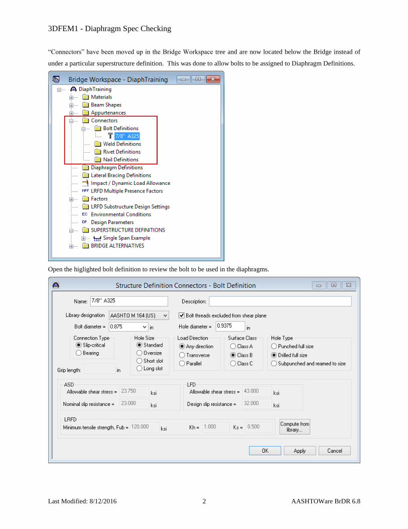
“Connectors” have been moved up in the Bridge Workspace tree and are now located below the Bridge instead of
under a particular superstructure definition. This was done to allow bolts to be assigned to Diaphragm Definitions.
Open the higlighted bolt definition to review the bolt to be used in the diaphragms.

3DFEM1 - Diaphragm Spec Checking
Last Modified: 8/12/2016 3 AASHTOWare BrDR 6.8
The following sketch illustrates the intermediate diaphragm that will be described for this example.
Double-click the “Diaphragm Definitions” folder and create the following diaphragm definition:
3DFEM1 - Diaphragm Spec Checking
Last Modified: 8/12/2016 4 AASHTOWare BrDR 6.8
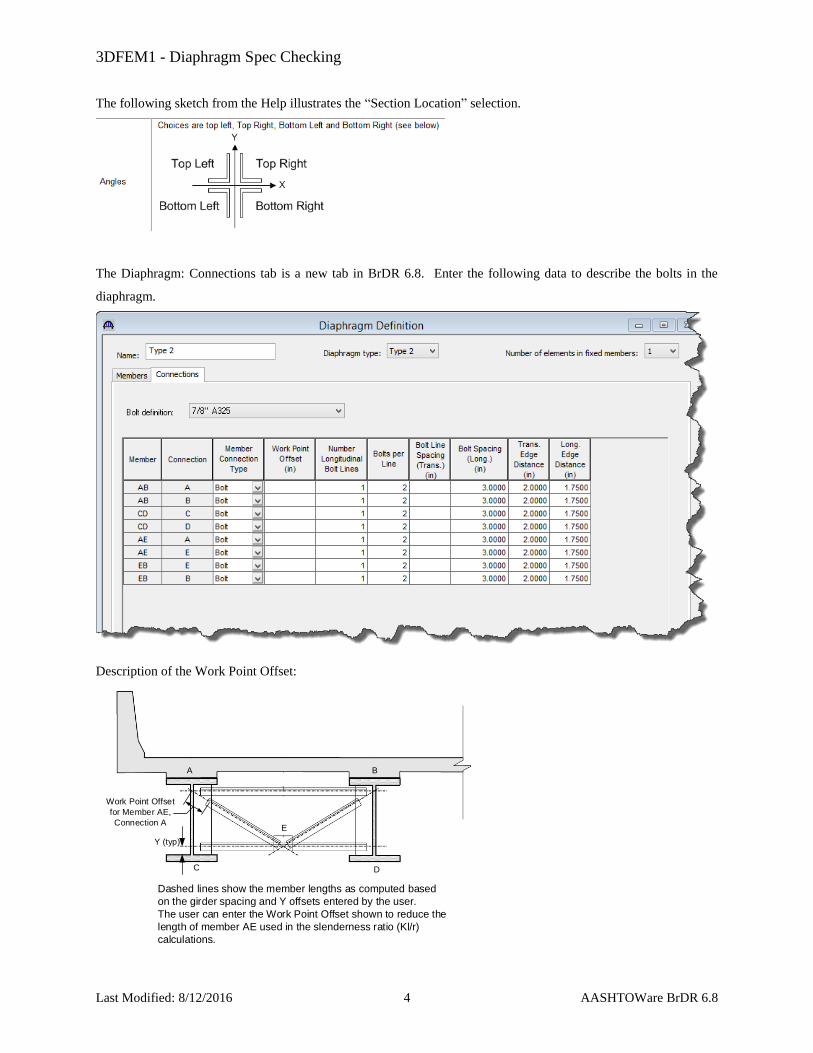
The following sketch from the Help illustrates the “Section Location” selection.
The Diaphragm: Connections tab is a new tab in BrDR 6.8. Enter the following data to describe the bolts in the
diaphragm.
Description of the Work Point Offset:
Dashed lines show the member lengths as computed based
on the girder spacing and Y offsets entered by the user.
The user can enter the Work Point Offset shown to reduce the
length of member AE used in the slenderness ratio (Kl/r)
calculations.
A B
C D
E
Y (typ)
Work Point Offset
for Member AE,
Connection A
3DFEM1 - Diaphragm Spec Checking
Last Modified: 8/12/2016 5 AASHTOWare BrDR 6.8
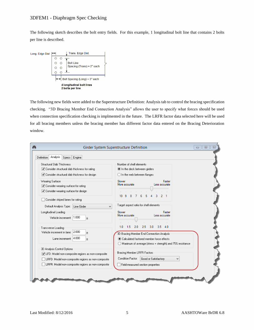
The following sketch describes the bolt entry fields. For this example, 1 longitudinal bolt line that contains 2 bolts
per line is described.
The following new fields were added to the Superstructure Definition: Analysis tab to control the bracing specification
checking. “3D Bracing Member End Connection Analysis” allows the user to specify what forces should be used
when connection specification checking is implmented in the future. The LRFR factor data selected here will be used
for all bracing members unless the bracing member has different factor data entered on the Bracing Deterioration
window.

3DFEM1 - Diaphragm Spec Checking
Last Modified: 8/12/2016 6 AASHTOWare BrDR 6.8
The finite element analysis can now consider wind load applied to the FE model. Open the Load Case Description
window and add the following load case for the wind load:
Open the Framing Plan Details: Diaphragms tab and assign the diaphragm definitions to the interior diaphragm
locations for all 3 girder bays:
3DFEM1 - Diaphragm Spec Checking
Last Modified: 8/12/2016 7 AASHTOWare BrDR 6.8
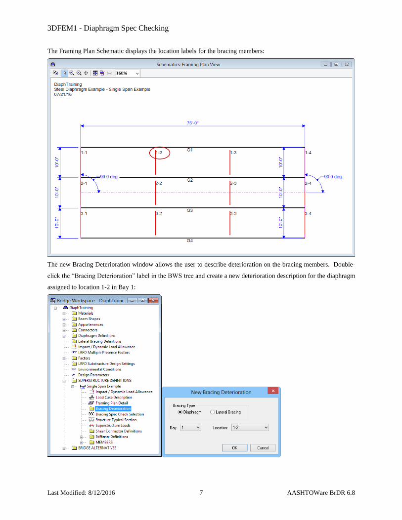
The Framing Plan Schematic displays the location labels for the bracing members:
The new Bracing Deterioration window allows the user to describe deterioration on the bracing members. Double-
click the “Bracing Deterioration” label in the BWS tree and create a new deterioration description for the diaphragm
assigned to location 1-2 in Bay 1:

3DFEM1 - Diaphragm Spec Checking
Last Modified: 8/12/2016 8 AASHTOWare BrDR 6.8
Enter the following values for section loss on Member AB. This section loss will be used in rating, not in design
review. The superstructure definition LRFR condition factor can also be overriden for this particular member on this
tab.
The Bracing Specification Check Selection window allows the user to select which diaphragms and lateral bracing
should be specification-checked:
3DFEM1 - Diaphragm Spec Checking
Last Modified: 8/12/2016 9 AASHTOWare BrDR 6.8
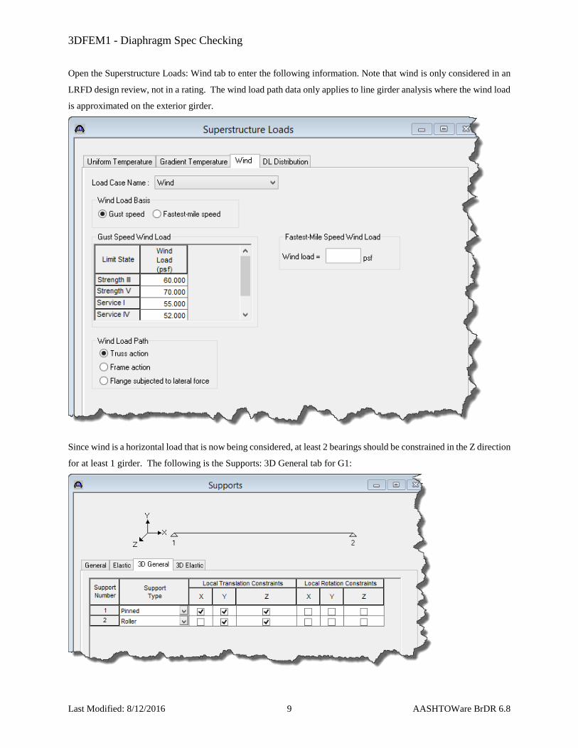
Open the Superstructure Loads: Wind tab to enter the following information. Note that wind is only considered in an
LRFD design review, not in a rating. The wind load path data only applies to line girder analysis where the wind load
is approximated on the exterior girder.
Since wind is a horizontal load that is now being considered, at least 2 bearings should be constrained in the Z direction
for at least 1 girder. The following is the Supports: 3D General tab for G1:
3DFEM1 - Diaphragm Spec Checking
Last Modified: 8/12/2016 10 AASHTOWare BrDR 6.8
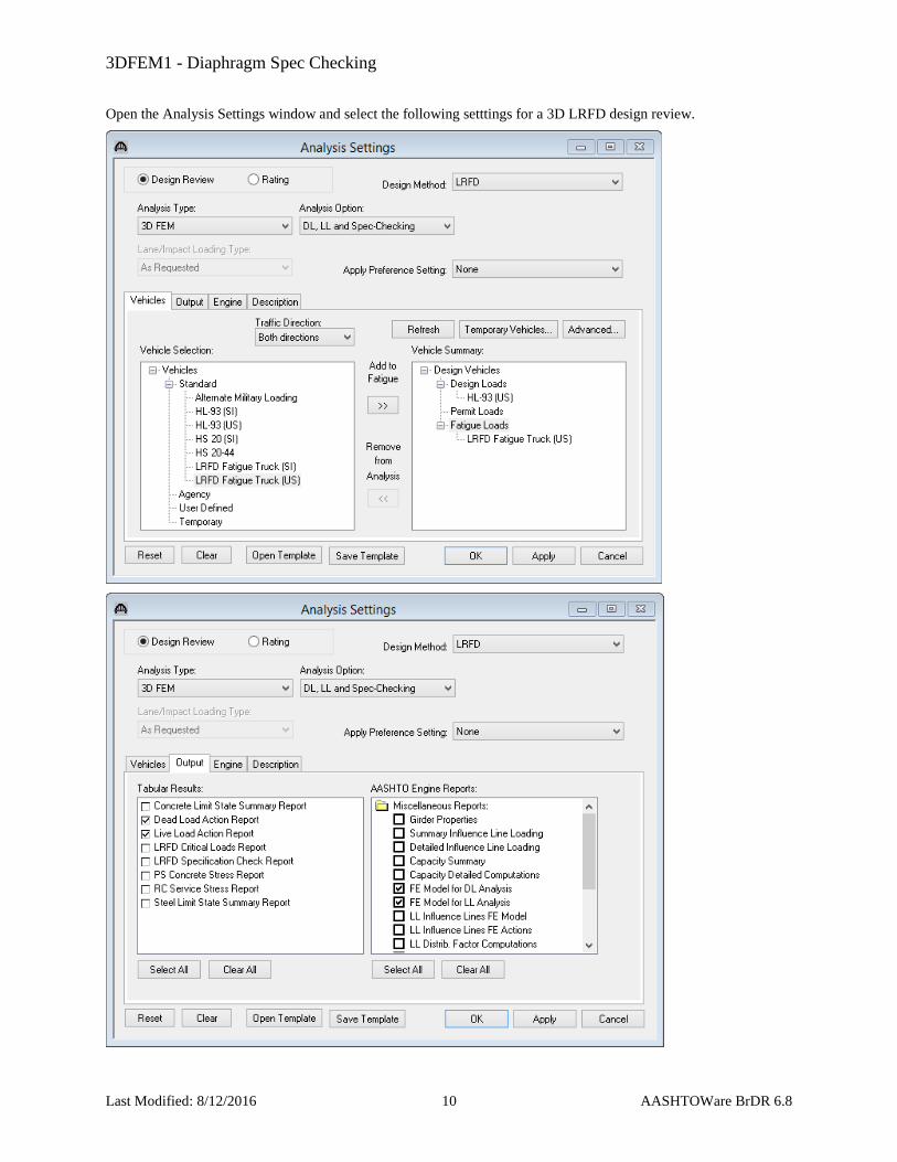
Open the Analysis Settings window and select the following setttings for a 3D LRFD design review.
3DFEM1 - Diaphragm Spec Checking
Last Modified: 8/12/2016 11 AASHTOWare BrDR 6.8
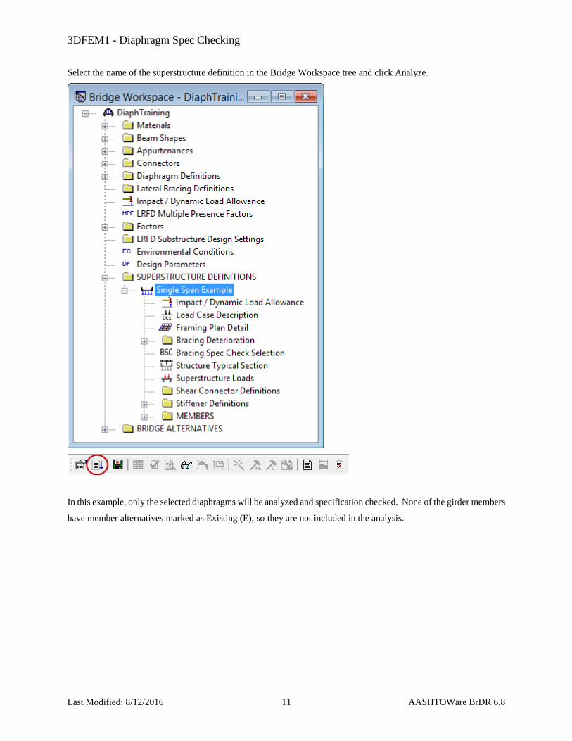
Select the name of the superstructure definition in the Bridge Workspace tree and click Analyze.
In this example, only the selected diaphragms will be analyzed and specification checked. None of the girder members
have member alternatives marked as Existing (E), so they are not included in the analysis.
3DFEM1 - Diaphragm Spec Checking
Last Modified: 8/12/2016 12 AASHTOWare BrDR 6.8
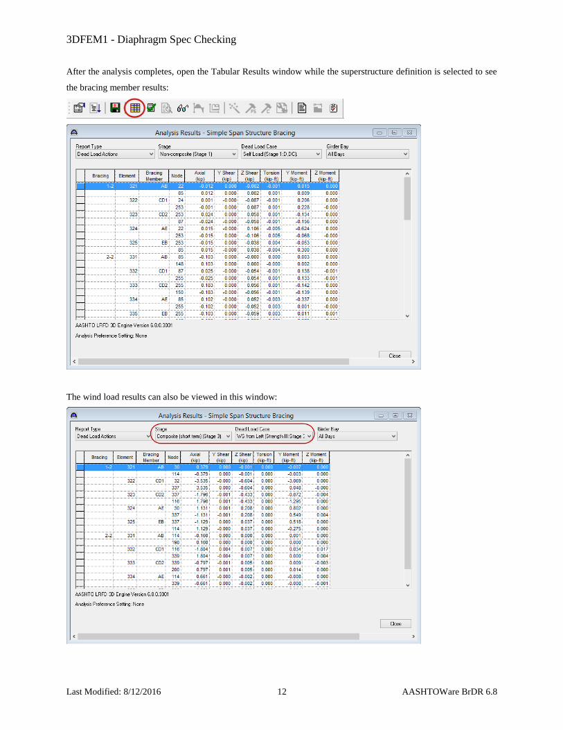
After the analysis completes, open the Tabular Results window while the superstructure definition is selected to see
the bracing member results:
The wind load results can also be viewed in this window:

3DFEM1 - Diaphragm Spec Checking
Last Modified: 8/12/2016 13 AASHTOWare BrDR 6.8
Specification check details can be viewed for the bracing members:
The following specification article illustrates how the wind load is combined with the live load:
3DFEM1 - Diaphragm Spec Checking
Last Modified: 8/12/2016 14 AASHTOWare BrDR 6.8
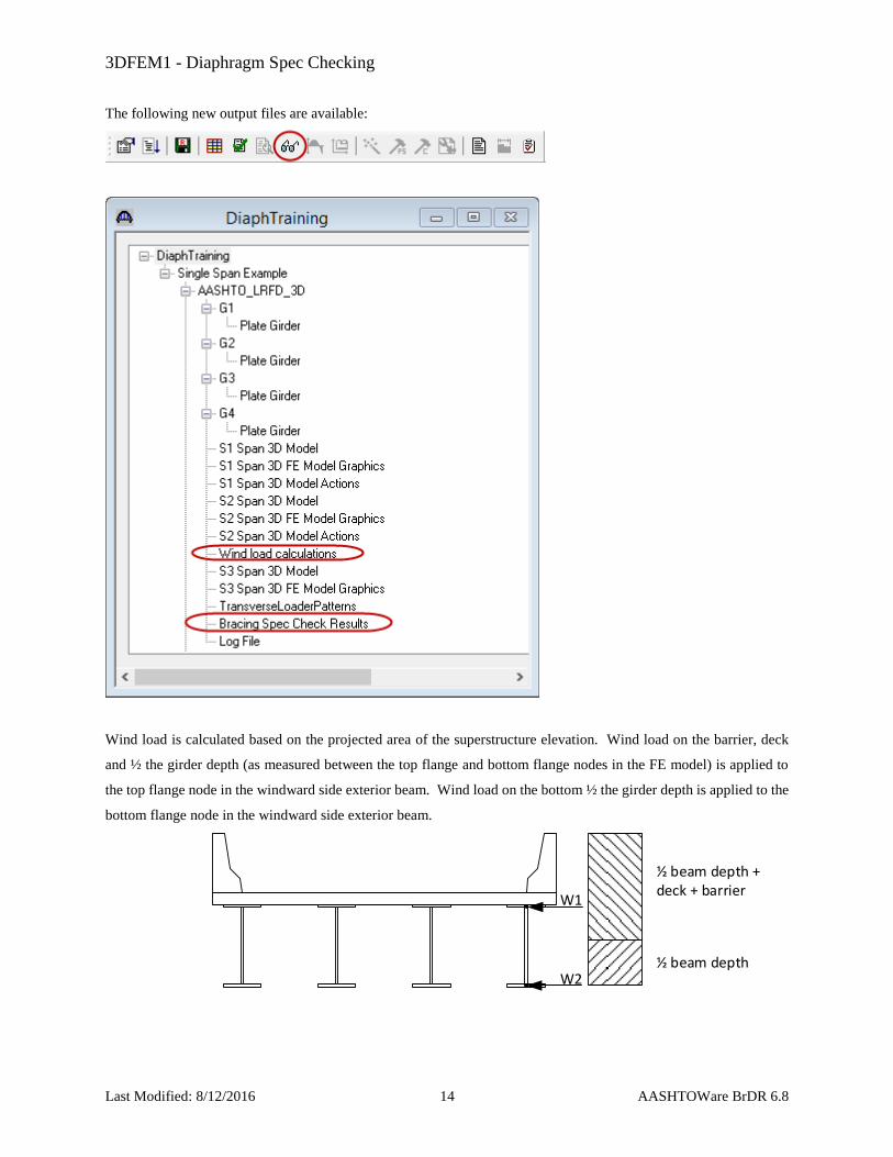
The following new output files are available:
Wind load is calculated based on the projected area of the superstructure elevation. Wind load on the barrier, deck
and ½ the girder depth (as measured between the top flange and bottom flange nodes in the FE model) is applied to
the top flange node in the windward side exterior beam. Wind load on the bottom ½ the girder depth is applied to the
bottom flange node in the windward side exterior beam.
½ beam depth + deck + barrier
½ beam depth
W1
W2
3DFEM1 - Diaphragm Spec Checking
Last Modified: 8/12/2016 15 AASHTOWare BrDR 6.8
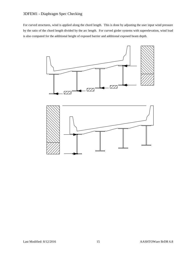
For curved structures, wind is applied along the chord length. This is done by adjusting the user input wind pressure
by the ratio of the chord length divided by the arc length. For curved girder systems with superelevation, wind load
is also computed for the additional height of exposed barrier and additional exposed beam depth.
3DFEM1 - Diaphragm Spec Checking
Last Modified: 8/12/2016 16 AASHTOWare BrDR 6.8
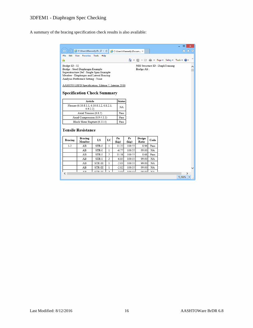
A summary of the bracing specification check results is also available:
3DFEM1 - Diaphragm Spec Checking
Last Modified: 8/12/2016 17 AASHTOWare BrDR 6.8
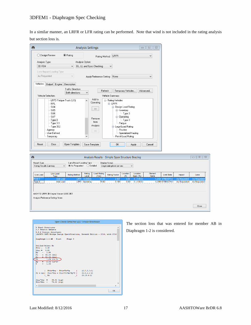
In a similar manner, an LRFR or LFR rating can be performed. Note that wind is not included in the rating analysis
but section loss is.
The section loss that was entered for member AB in
Diaphragm 1-2 is considered.
3DFEM1 - Diaphragm Spec Checking
Last Modified: 8/12/2016 18 AASHTOWare BrDR 6.8
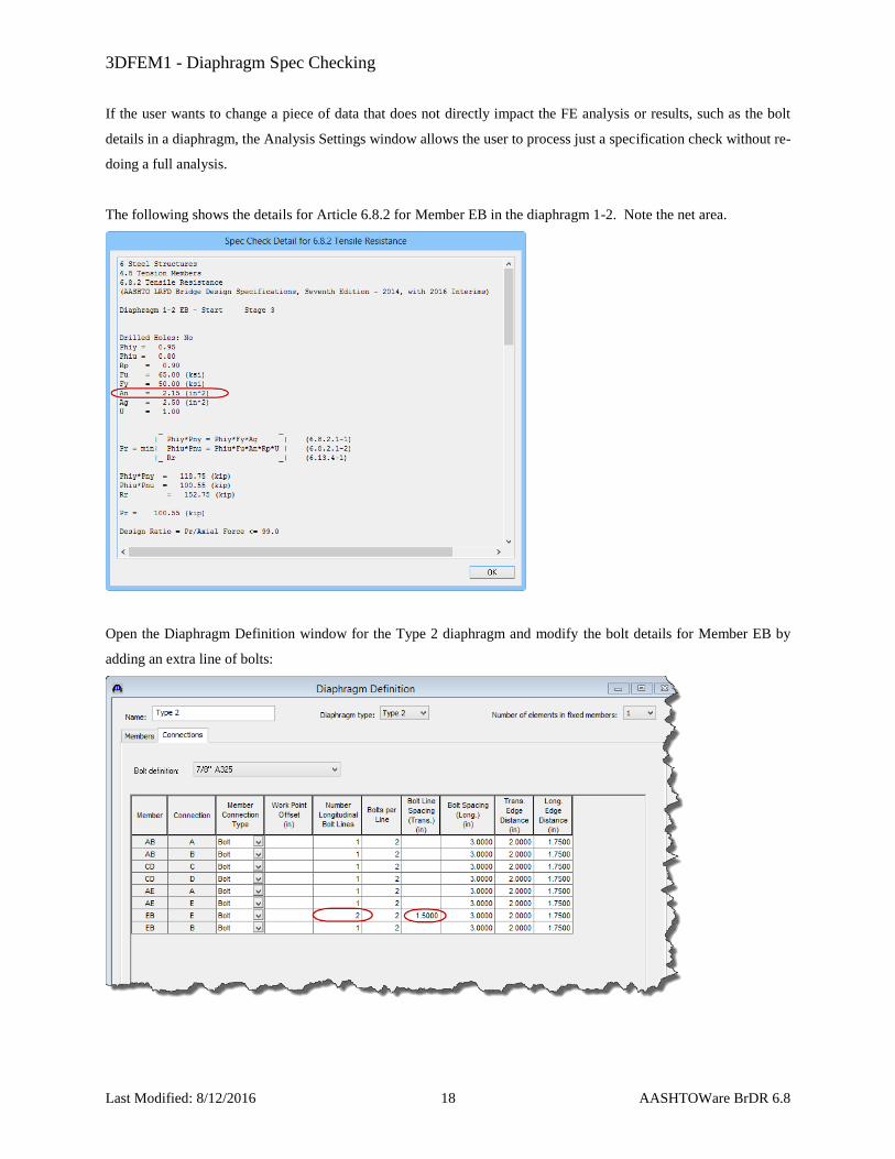
If the user wants to change a piece of data that does not directly impact the FE analysis or results, such as the bolt
details in a diaphragm, the Analysis Settings window allows the user to process just a specification check without re-
doing a full analysis.
The following shows the details for Article 6.8.2 for Member EB in the diaphragm 1-2. Note the net area.
Open the Diaphragm Definition window for the Type 2 diaphragm and modify the bolt details for Member EB by
adding an extra line of bolts:
3DFEM1 - Diaphragm Spec Checking
Last Modified: 8/12/2016 19 AASHTOWare BrDR 6.8
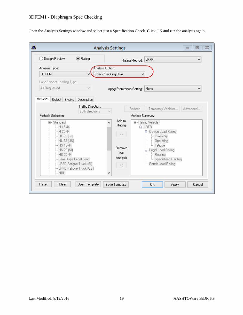
Open the Analysis Settings window and select just a Specification Check. Click OK and run the analysis again.

3DFEM1 - Diaphragm Spec Checking
Last Modified: 8/12/2016 20 AASHTOWare BrDR 6.8
BrDR will regenerate the FE Models and compare them to the previously generated FE models. Since the models are
the same, the previous FE results are re-used and the specification checking considers the revised details: