3d from images - vcg
TRANSCRIPT
3D from photosphotogrammetry
MARCO CALLIERIV I S UA L C O M P U T I N G L A B
I S T I - C N R P I S A , I TA LY
3 D D I G I T I Z AT I O NF O R C U LT U R A L H E R I TAG E
3D from Images
Our not-so-secret dream: obtain a reliable and precise 3D from simple photos…
Why ?
Easier, cheaper and more versatile than a 3D scanner
We can perceive 3D shapes from “images”, why should a
computer not be able to do the same?
PASSIVE technique, we just look at the scene, without introducing any illumination. Geometry is determined only from “geometric” optical rules…
Basic ingredients
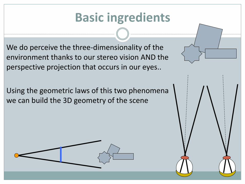
We do perceive the three-dimensionality of the environment thanks to our stereo vision AND the perspective projection that occurs in our eyes..
Using the geometric laws of this two phenomena we can build the 3D geometry of the scene
Perspective
Perspective Projection is used because it is an objective, unambiguous 2D representation of a 3D scene
IF you know “everything” about the perspective projection used by the camera at the time of the photo, it is possible to establish useful geometric relationship between the image and the geometry of the scene.
What is “everything”? We’ll see…
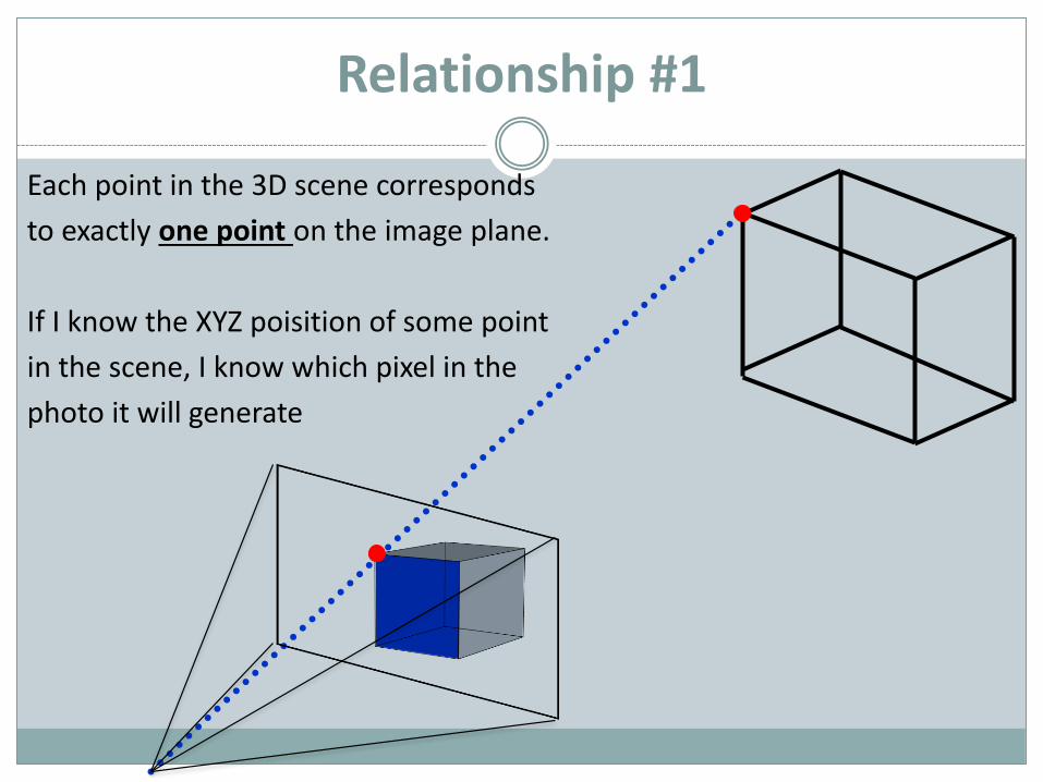
Relationship #1
Each point in the 3D scene corresponds
to exactly one point on the image plane.
If I know the XYZ poisition of some point
in the scene, I know which pixel in the
photo it will generate
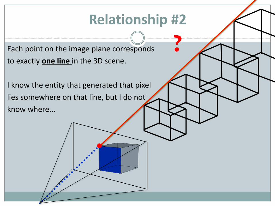
Relationship #2
Each point on the image plane corresponds
to exactly one line in the 3D scene.
I know the entity that generated that pixel
lies somewhere on that line, but I do not
know where...
?
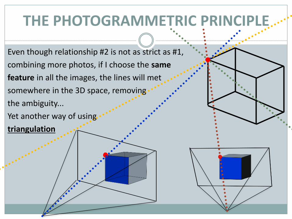
Even though relationship #2 is not as strict as #1,
combining more photos, if I choose the same
feature in all the images, the lines will met
somewhere in the 3D space, removing
the ambiguity...
Yet another way of using
triangulation
THE PHOTOGRAMMETRIC PRINCIPLE
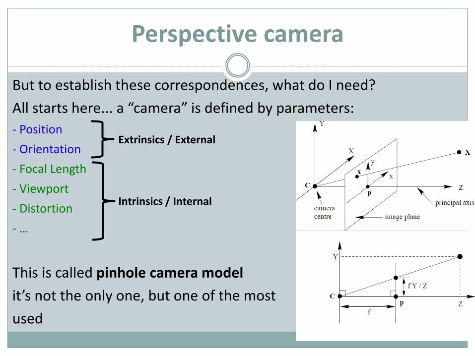
Perspective camera
But to establish these correspondences, what do I need?
All starts here... a “camera” is defined by parameters:
- Position
- Orientation
- Focal Length
- Viewport
- Distortion
- …
This is called pinhole camera model
it’s not the only one, but one of the most
used
Extrinsics / External
Intrinsics / Internal
UROBOROS
But, in this way, It is a snake biting its own tail!
In order to know the scene geometry, you do need to know the scene geometry…
We are lucky: by providing “semantic” information (non metric), it is possible to obtain all the data we need.
There is a mathematical-geometrical procedure that, starting from image-to-image points correspondences, returns the internal and external, plus the 3D location of the points picked as correspondences.
Calibration + Orientation
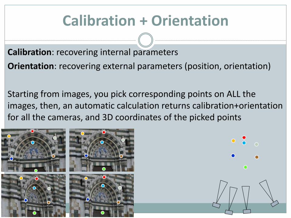
Calibration: recovering internal parameters
Orientation: recovering external parameters (position, orientation)
Starting from images, you pick corresponding points on ALL the images, then, an automatic calculation returns calibration+orientationfor all the cameras, and 3D coordinates of the picked points
Calibration + Orientation
How many correspondences we need to calibrate-orient the cameras?
Unfortunately, the answer is: it depends….
The process is mathematicalli ill-conditioned, and there are manylocal minima and abiguities.
To give a range, between 8 to 15 corresponding points per image.
What normally happens is that you start adding correspondences, and at one point the software is able to find a solution, and it tellsyou.
Not just "by hand"
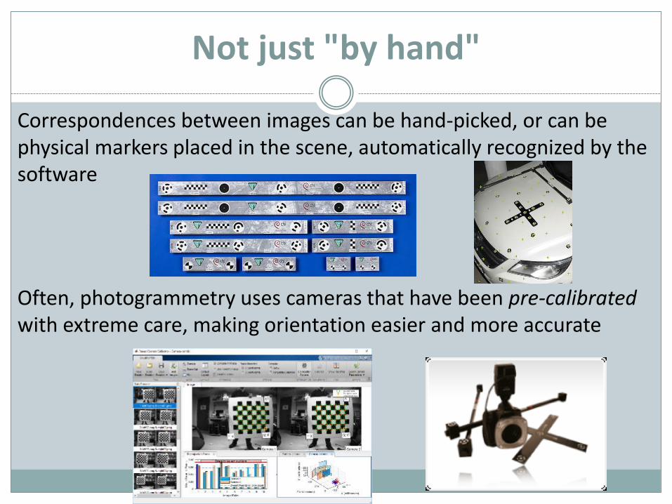
Correspondences between images can be hand-picked, or can be physical markers placed in the scene, automatically recognized by the software
Often, photogrammetry uses cameras that have been pre-calibratedwith extreme care, making orientation easier and more accurate
Workflow
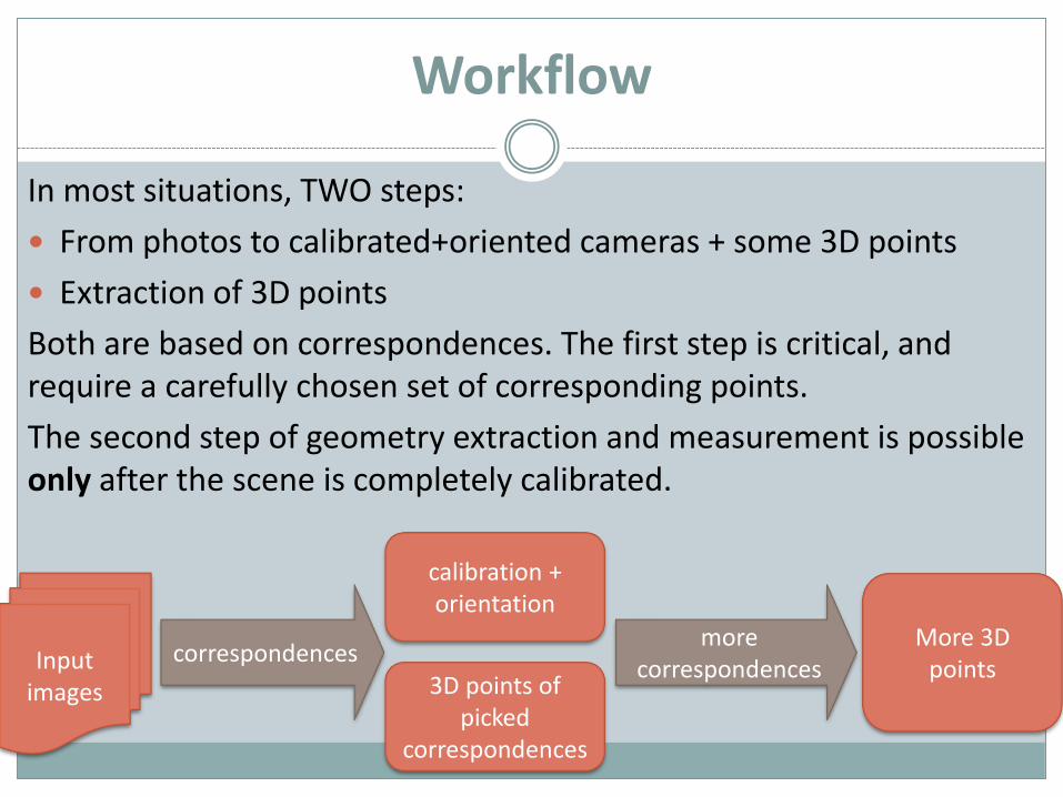
In most situations, TWO steps:
From photos to calibrated+oriented cameras + some 3D points
Extraction of 3D points
Both are based on correspondences. The first step is critical, and require a carefully chosen set of corresponding points.
The second step of geometry extraction and measurement is possible only after the scene is completely calibrated.
Input images
calibration + orientation
3D points of picked
correspondences
More 3D points
correspondencesmore
correspondences
Photogrammetry
Photogrammetry is the name of the principle; many different
tools and approaches.
At first seems impossible but, with some care, the obtained
precision is way below the projected size of a pixel.
For a building, it may be few millimeters
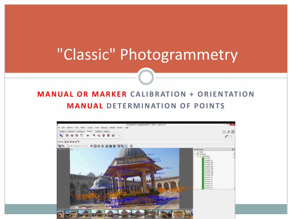
M A N UA L O R M A R K E R C A L I B R AT I O N + O R I E N TAT I O N
M A N UA L D E T E R M I N AT I O N O F P O I N T S
"Classic" Photogrammetry
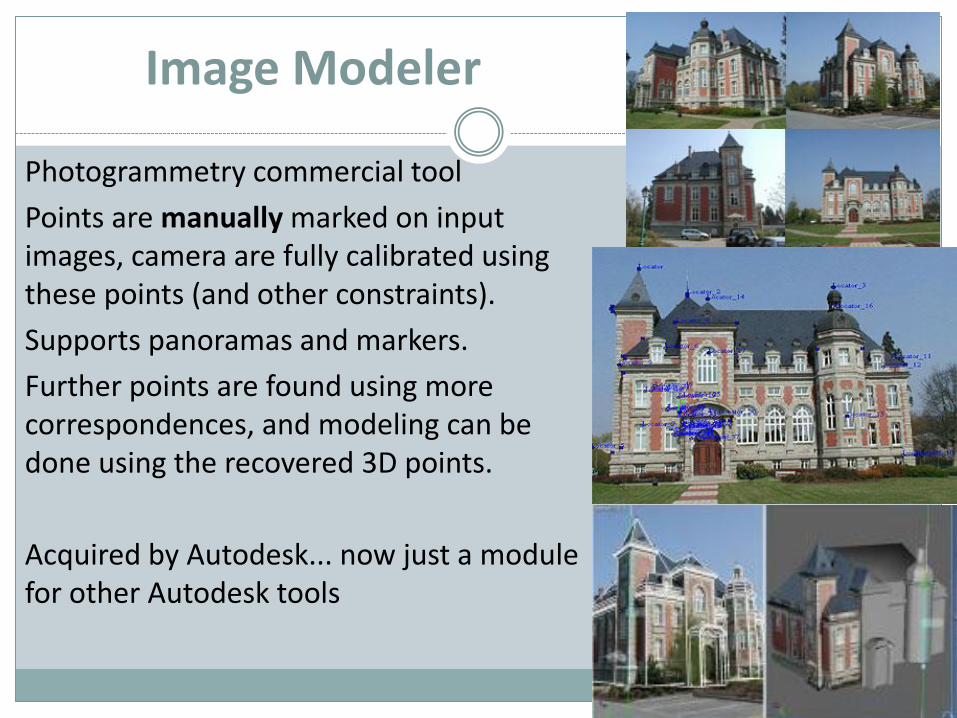
Image Modeler
Photogrammetry commercial tool
Points are manually marked on input images, camera are fully calibrated using these points (and other constraints).
Supports panoramas and markers.
Further points are found using more correspondences, and modeling can be done using the recovered 3D points.
Acquired by Autodesk... now just a module for other Autodesk tools
PhotoModeler
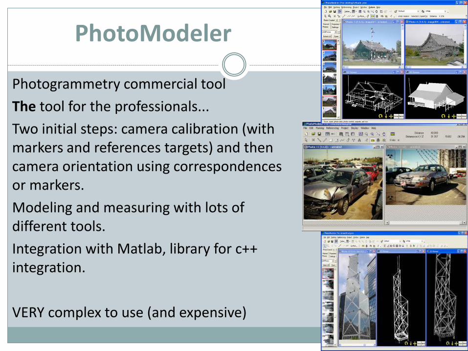
Photogrammetry commercial tool
The tool for the professionals...
Two initial steps: camera calibration (with markers and references targets) and then camera orientation using correspondences or markers.
Modeling and measuring with lots of different tools.
Integration with Matlab, library for c++integration.
VERY complex to use (and expensive)
XSIGNO
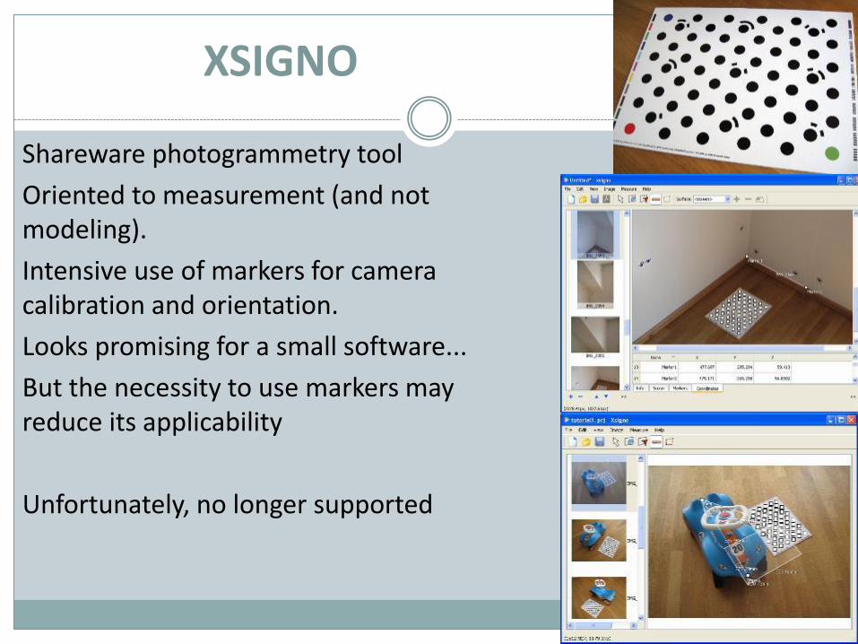
Shareware photogrammetry tool
Oriented to measurement (and not modeling).
Intensive use of markers for camera calibration and orientation.
Looks promising for a small software...
But the necessity to use markers may reduce its applicability
Unfortunately, no longer supported
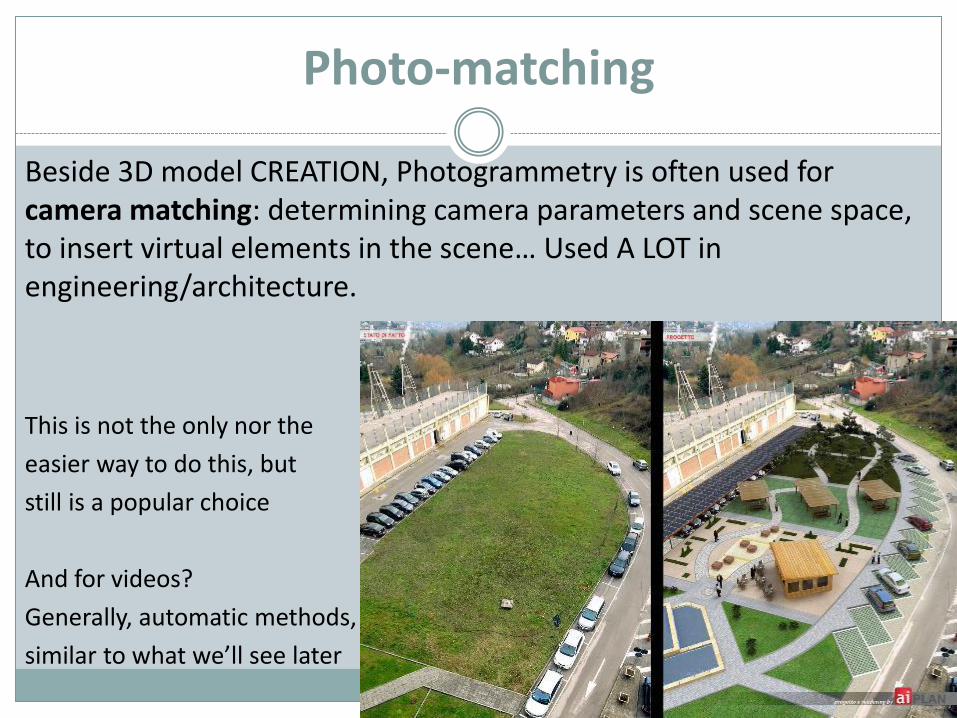
Photo-matching
Beside 3D model CREATION, Photogrammetry is often used for camera matching: determining camera parameters and scene space, to insert virtual elements in the scene… Used A LOT in engineering/architecture.
This is not the only nor the
easier way to do this, but
still is a popular choice
And for videos?
Generally, automatic methods,
similar to what we’ll see later
The sad news…
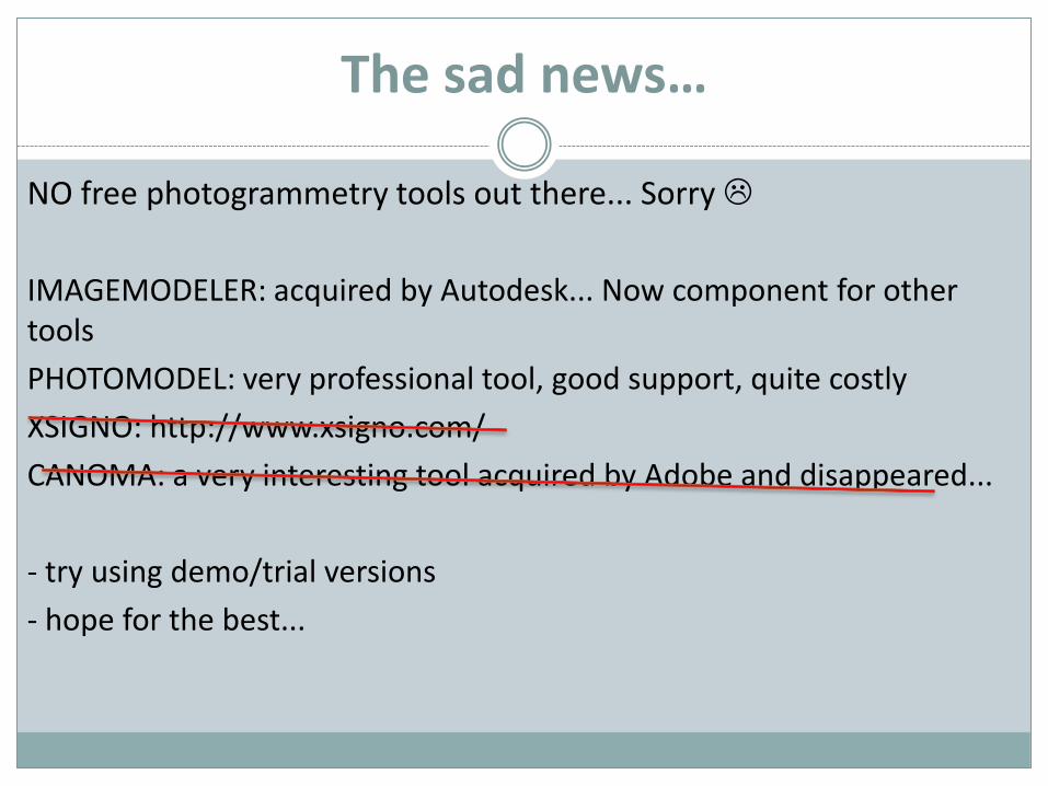
NO free photogrammetry tools out there... Sorry
IMAGEMODELER: acquired by Autodesk... Now component for other tools
PHOTOMODEL: very professional tool, good support, quite costly
XSIGNO: http://www.xsigno.com/
CANOMA: a very interesting tool acquired by Adobe and disappeared...
- try using demo/trial versions
- hope for the best...
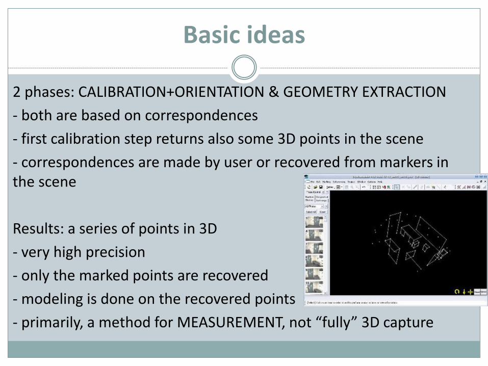
Basic ideas
2 phases: CALIBRATION+ORIENTATION & GEOMETRY EXTRACTION
- both are based on correspondences
- first calibration step returns also some 3D points in the scene
- correspondences are made by user or recovered from markers in the scene
Results: a series of points in 3D
- very high precision
- only the marked points are recovered
- modeling is done on the recovered points
- primarily, a method for MEASUREMENT, not “fully” 3D capture
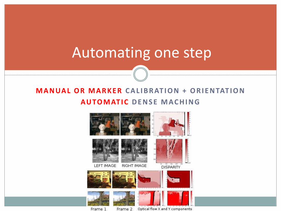
M A N UA L O R M A R K E R C A L I B R AT I O N + O R I E N TAT I O N
AU TO M AT I C D E N S E M AC H I N G
Automating one step
Dense matching
The calibration/orientation step is good. However, getting 3D points is tedious and does not scale well.
Idea: use some kind of automatic feature matching to perform a DENSE reconstruction... Not just rely on user-picked points, but try to match the entire surface, pixel by pixel..
Basic situation:
- camera calibration+orientation is reached with manual correspondences, markers or somehow pre-determined.
- 3D points extraction is done through automatic matching between image pixels, to have a DENSE reconstruction
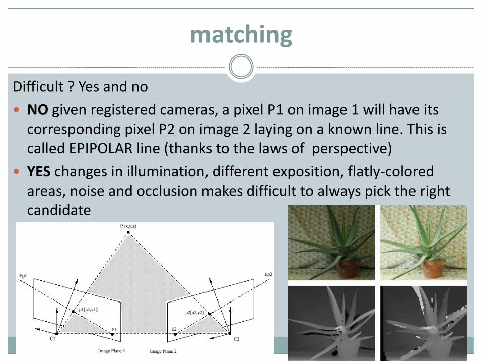
matching
Difficult ? Yes and no
NO given registered cameras, a pixel P1 on image 1 will have its corresponding pixel P2 on image 2 laying on a known line. This is called EPIPOLAR line (thanks to the laws of perspective)
YES changes in illumination, different exposition, flatly-coloredareas, noise and occlusion makes difficult to always pick the right candidate
Shape from Stereo
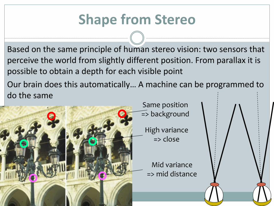
Based on the same principle of human stereo vision: two sensors that perceive the world from slightly different position. From parallax it is possible to obtain a depth for each visible point
Our brain does this automatically… A machine can be programmed to do the same
Same position=> background
High variance=> close
Mid variance=> mid distance
Dedicated Devices
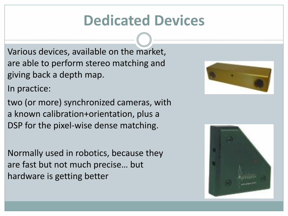
Various devices, available on the market, are able to perform stereo matching and giving back a depth map.
In practice:
two (or more) synchronized cameras, with a known calibration+orientation, plus a DSP for the pixel-wise dense matching.
Normally used in robotics, because they are fast but not much precise… but hardware is getting better
PhotoModeler - DENSE
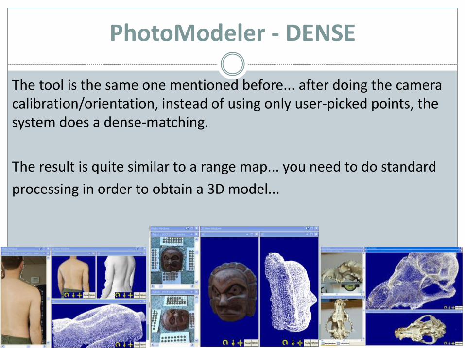
The tool is the same one mentioned before... after doing the camera calibration/orientation, instead of using only user-picked points, the system does a dense-matching.
The result is quite similar to a range map... you need to do standard
processing in order to obtain a 3D model...
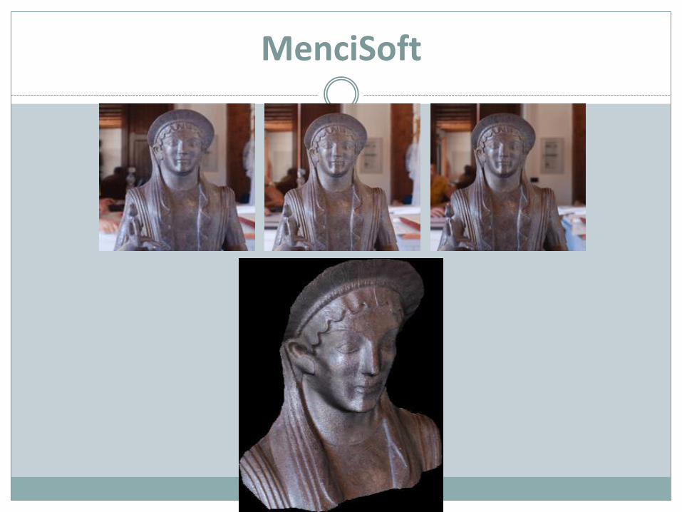
MenciSoft
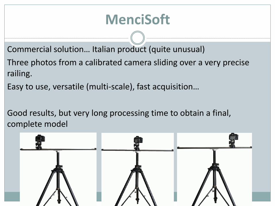
Commercial solution… Italian product (quite unusual)
Three photos from a calibrated camera sliding over a very precise railing.
Easy to use, versatile (multi-scale), fast acquisition…
Good results, but very long processing time to obtain a final, complete model
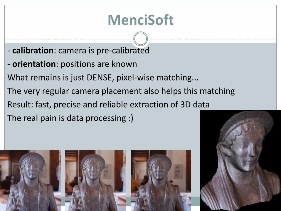
MenciSoft
- calibration: camera is pre-calibrated
- orientation: positions are known
What remains is just DENSE, pixel-wise matching...
The very regular camera placement also helps this matching
Result: fast, precise and reliable extraction of 3D data
The real pain is data processing :)
MenciSoft
AU TO M AT I C C A L I B R AT I O N + O R I E N TAT I O N
AU TO M AT I C D E N S E M AC H I N G
Fully Automatic Photogrammetry
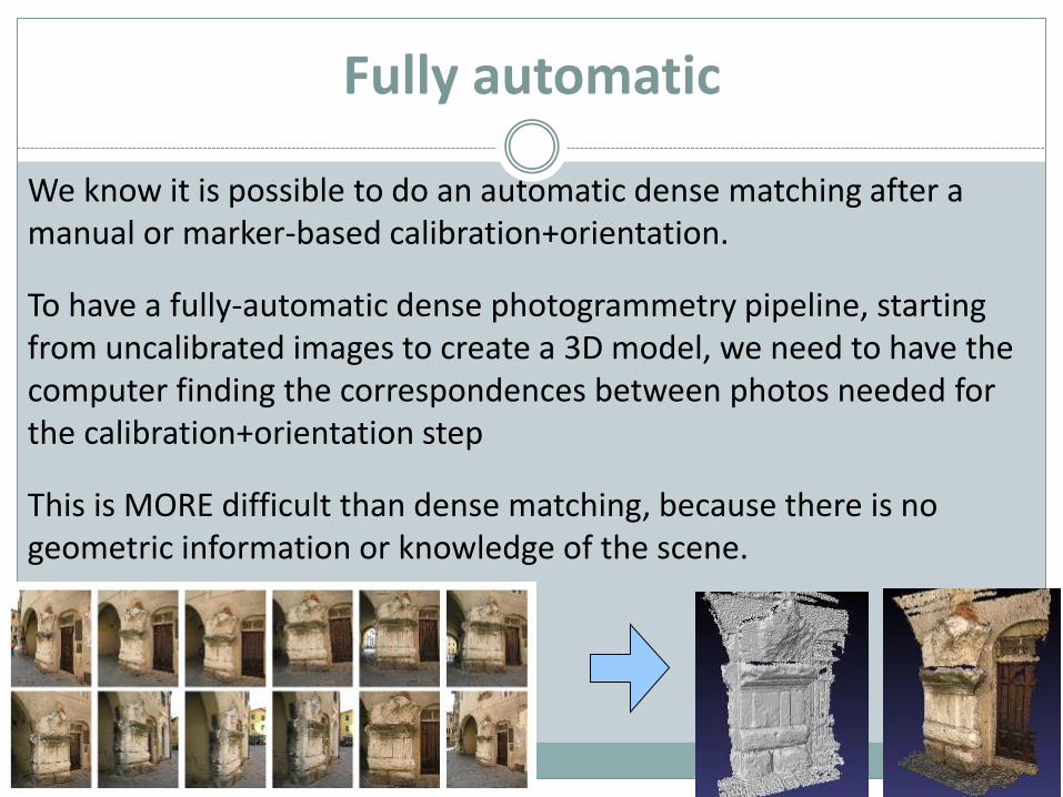
Fully automatic
We know it is possible to do an automatic dense matching after a manual or marker-based calibration+orientation.
To have a fully-automatic dense photogrammetry pipeline, starting from uncalibrated images to create a 3D model, we need to have the computer finding the correspondences between photos needed for the calibration+orientation step
This is MORE difficult than dense matching, because there is no geometric information or knowledge of the scene.
Calibration + Orientation step
In the previous examples, correspondences for the calibration+orientation step were hand picked (or usedmarkers).
We cannot brute-force try matching every pixel of everyphotos. Ineffective and too long.
The computer needs to reason on a some "interesting" points, like we do.
SIFT - SURF
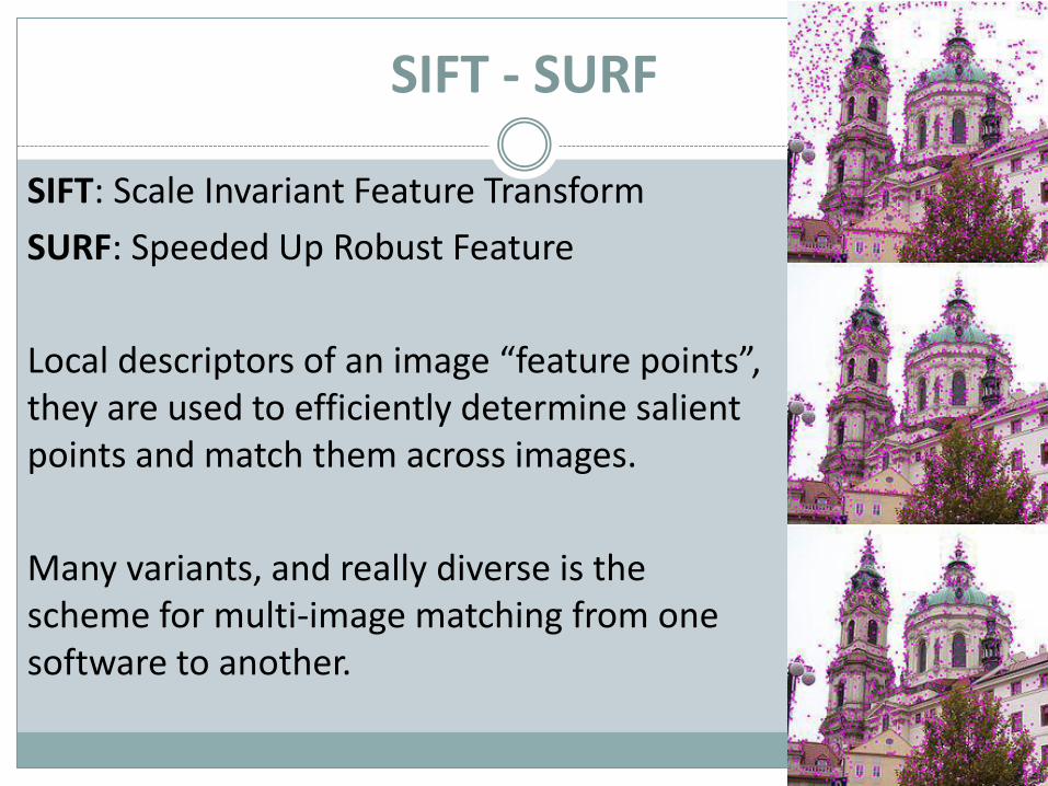
SIFT: Scale Invariant Feature Transform
SURF: Speeded Up Robust Feature
Local descriptors of an image “feature points”, they are used to efficiently determine salient points and match them across images.
Many variants, and really diverse is the scheme for multi-image matching from one software to another.
Bag of Features
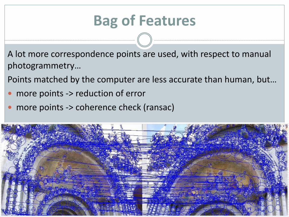
A lot more correspondence points are used, with respect to manual photogrammetry…
Points matched by the computer are less accurate than human, but…
more points -> reduction of error
more points -> coherence check (ransac)
Working principle
All the existing tools follow the same scheme:
⚫ Using euristincs and local analysis, find some salient points in the input images.
⚫ Match the salient points across images, determining overlap between images (bag of features).
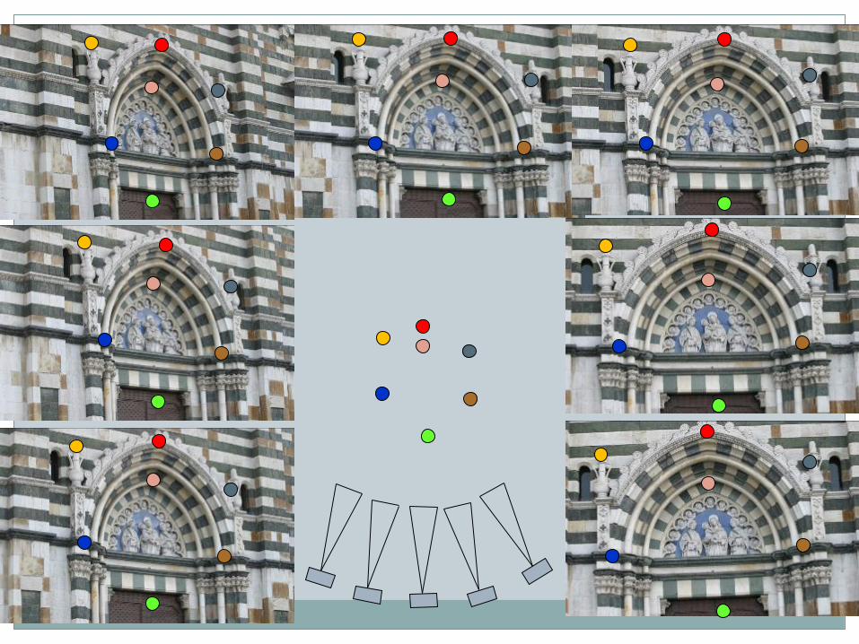
⚫ From the matched points, determine calibration+orientation of the cameras at the time of the shot.
⚫ Using the computed cameras, perform a dense match trying to determine 3D coordinates for all pixels.
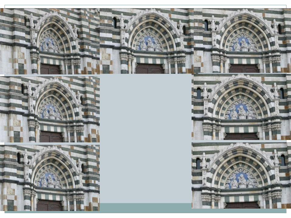
Working principle
3D scanning
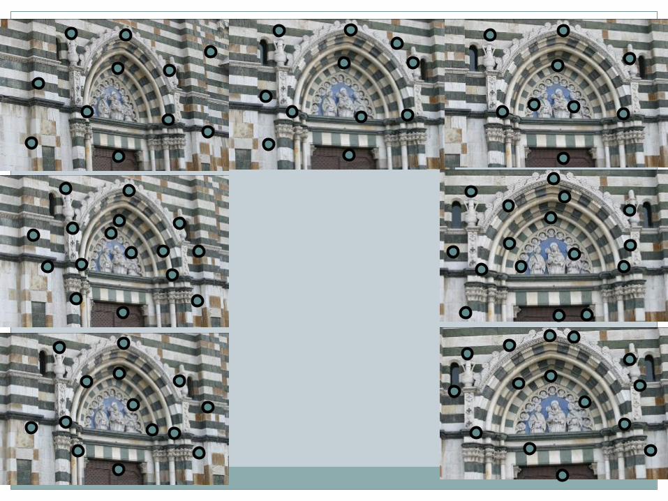
Working principle
3D scanning

Working principle
3D scanning
Working principle
3D scanning
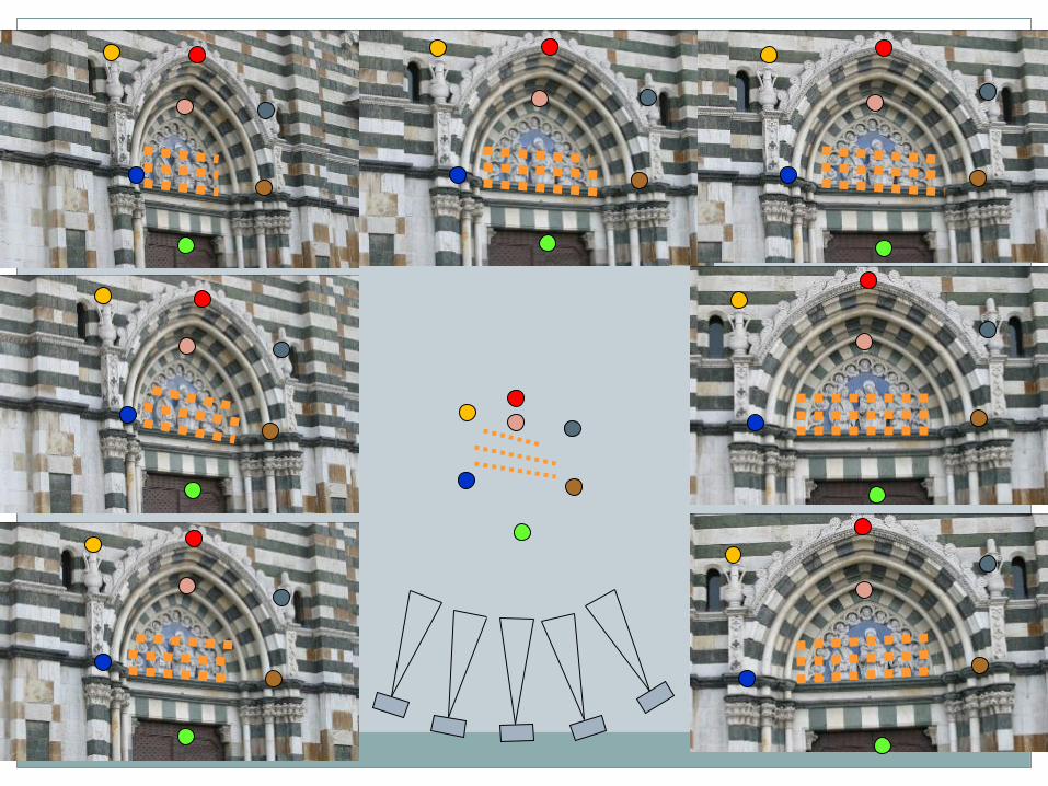
Working principle
3D scanning
All for one, one for all
Another component used in these tools is:
Bundle Adjustement
Cameras are determined independently, using the detected corresponences, and a global optimization step is often necessary to ensure a good fitting.
Many ready-to-use libraries for bundle adjustement exists...
A problem of SCALE
All these tools have a problem in common: the returned geometry is at an unknown scale... every proportion is correct, it is only that the measure unit is unknown. This is because nothing is known about the scene and the camera (you may have been taken a photo of a car or of a car model).
How to solve this? You need a measurement taken on the real object and the corresponding measure from the computed 3D model to calculate the scale factor!
Most tools have a way to calculate/specify this scaling factor at the time of model creation... in any case, it will always be possible to apply a scaling factor to the whole result :).
A problem of SCALE
This issue is common also to pure Photogrammetry tools!
Photogrammetry software has inbuilt tools to apply scale, with multiple measurements and residual error calculation.
If you are using markers of known size/pattern size, or some metric details of the scene are known (like the offset of the camera in the MENCI tool), the scale is calculated automatically.
A plethora of tools
Using 3D from images is easy, you need a camera and one of the many software tools...
A lot of free tools, often a "toolchain" of existing tools.
Some semi-free or very cheap software.
Many commercial implementations, sometimes bundled to custom-made devices.
Online - Offline
Computing 3D reconstruction from photos is a cumbersome task, computationally. A reconstruction may take hours, or even more than one day...
For this reason some tools are implemented as web-services.
The data is sent to a remote server, ad you receive the results
☺ Good performances, remote code is regularly updated
You need network access, you have to send away your data
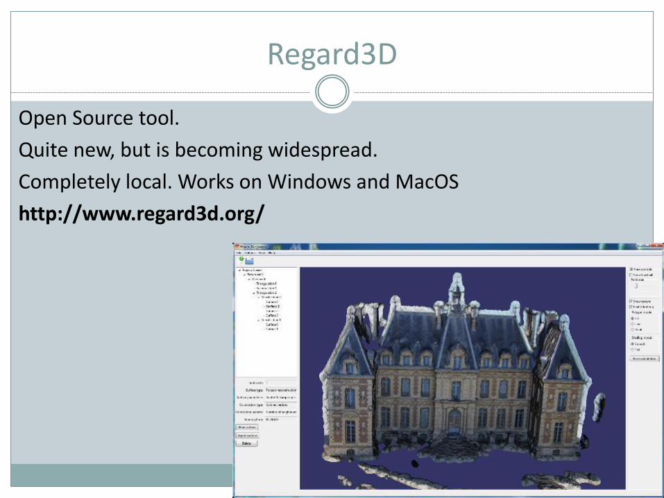
Regard3D
Open Source tool.
Quite new, but is becoming widespread.
Completely local. Works on Windows and MacOS
http://www.regard3d.org/
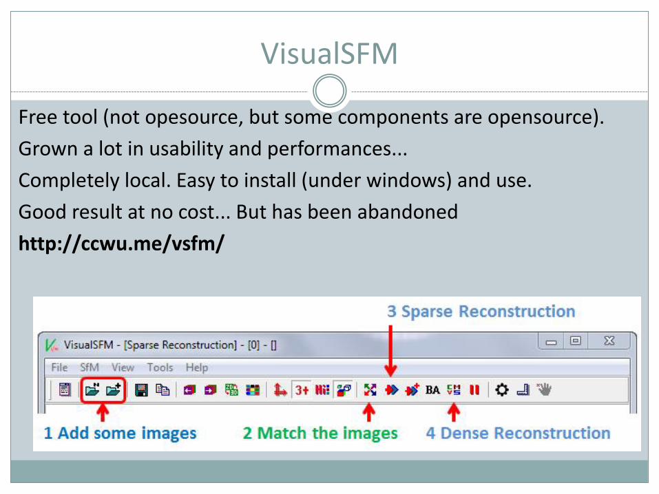
VisualSFM
Free tool (not opesource, but some components are opensource).
Grown a lot in usability and performances...
Completely local. Easy to install (under windows) and use.
Good result at no cost... But has been abandoned
http://ccwu.me/vsfm/
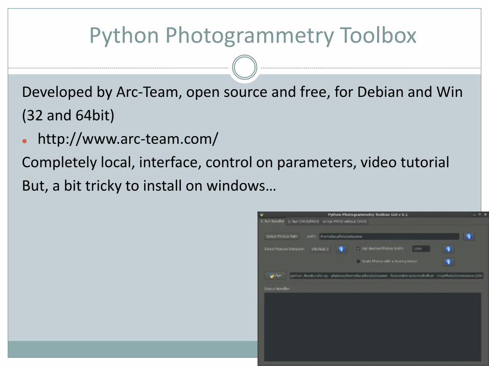
Python Photogrammetry Toolbox
Developed by Arc-Team, open source and free, for Debian and Win
(32 and 64bit)
⚫ http://www.arc-team.com/
Completely local, interface, control on parameters, video tutorial
But, a bit tricky to install on windows…
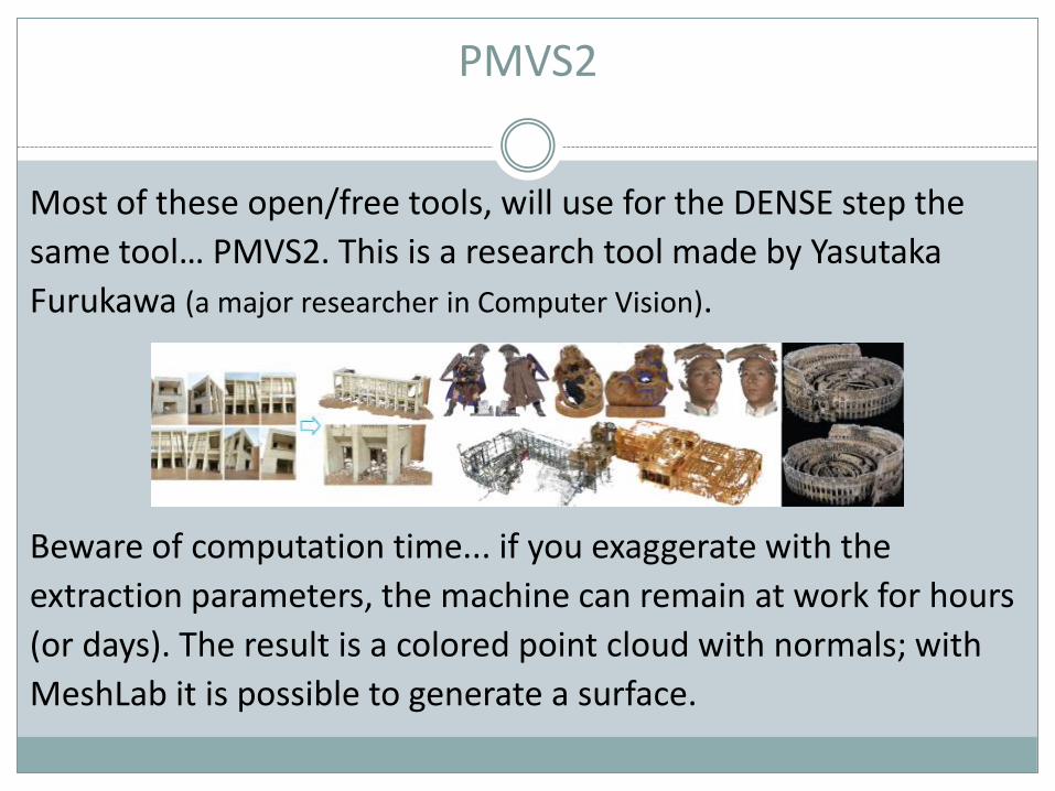
PMVS2
Most of these open/free tools, will use for the DENSE step the
same tool… PMVS2. This is a research tool made by Yasutaka
Furukawa (a major researcher in Computer Vision).
Beware of computation time... if you exaggerate with the
extraction parameters, the machine can remain at work for hours
(or days). The result is a colored point cloud with normals; with
MeshLab it is possible to generate a surface.
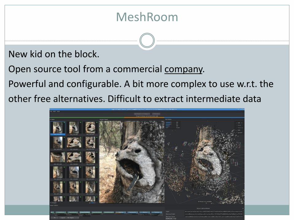
MeshRoom
New kid on the block.
Open source tool from a commercial company.
Powerful and configurable. A bit more complex to use w.r.t. the
other free alternatives. Difficult to extract intermediate data
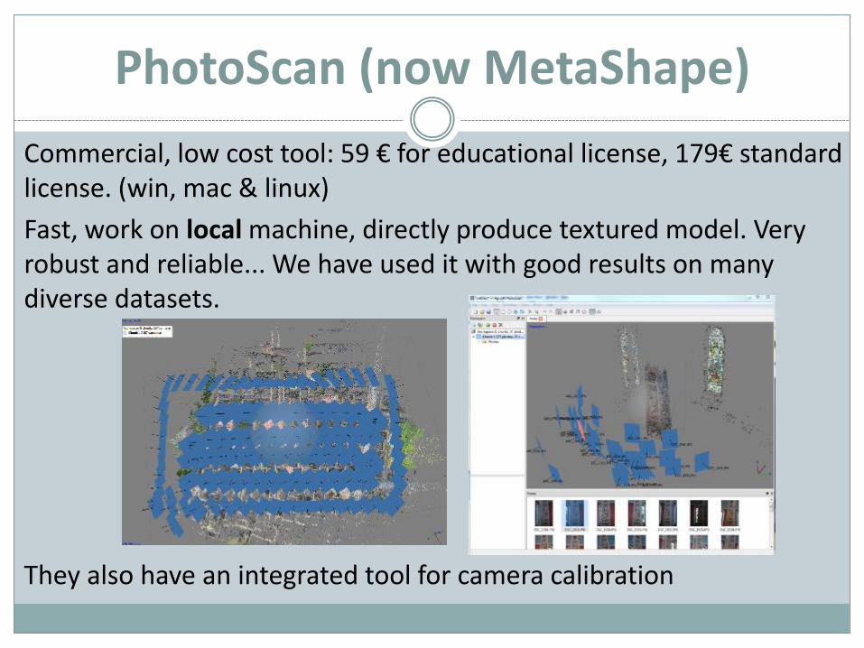
PhotoScan (now MetaShape)
Commercial, low cost tool: 59 € for educational license, 179€ standard license. (win, mac & linux)
Fast, work on local machine, directly produce textured model. Very robust and reliable... We have used it with good results on many diverse datasets.
They also have an integrated tool for camera calibration
PhotoScan (now MetaShape)
Photoscan is the DE FACTO standard tool in CH...
It’s cheap, easy to use, and reliable.
It works incredibly well with DRONES
PRO version has a georeferencing tool, can use markers for automatic scaling, and has a lot of exporting features specific for survey, CAD and GIS tools.
Reality Capture
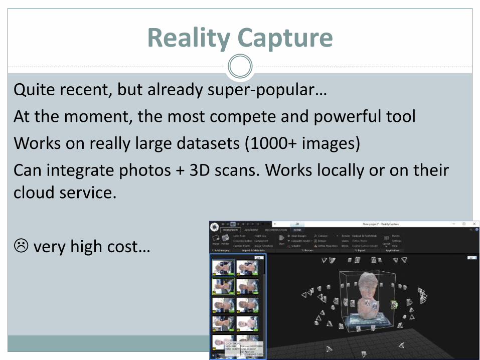
Quite recent, but already super-popular…
At the moment, the most compete and powerful tool
Works on really large datasets (1000+ images)
Can integrate photos + 3D scans. Works locally or on their cloud service.
very high cost…
Autodesk ReCap
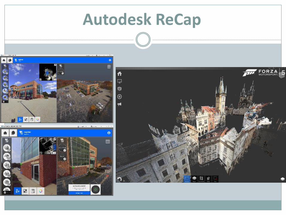
Previously known as, 123DCatch, Memento, ...
Very well engineered tool...
⚫ Works on a remote server or locally
⚫ Produces a complete, textured model
⚫ A full-fledged 3D digitization & processing tool, from scan/photo to CAD and printable models
Has a limited free version...
It is fast, and works very well , is able to reconstruct difficult
datasets and the results looks good.
Autodesk ReCap
Others
COLMAP: free, seems powerful but I have seen manypeople having problems in runnin it (I never tried, t.b.h.)
3D Zephir: commercial, but with limited trial, easy to use
Pix4D: commercial, mainly for drones
Bentley ContextCapture: commercial, large scale, for huge projects, super-expensive
A G O O D 3 D D E P E N D S O N A G O O D P H OTO G R A P H I C S U RV E Y
Garbage inGarbage out
Photos
And now, let us talk about the photos...
Do not worry if your first set does not comes out, retry, trying to understand what went wrong.
We will give basic rules, try to follow them at the begin, and the more you got experienced, you will see some may be regarded only as «suggestions»
Equipment
What kind of camera should I use?
More pixels = more 3D points = longer upload and processing time
Using 20-30 Mpixel photos will probably crash the tools, 5-10 are ok, and the result will be better than expected
Good lens → less distortion → better result
Good lens →more light → better result
A good compact camera may be enough. DSLR have better lenses.
Mirrorless may distort too much (avoid pancake lenses).
Good sequence
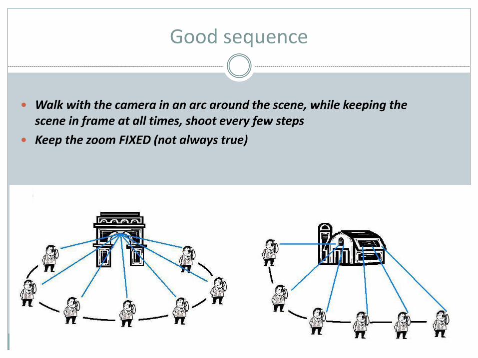
Walk with the camera in an arc around the scene, while keeping the scene in frame at all times, shoot every few steps
Keep the zoom FIXED (not always true)
Bad sequences
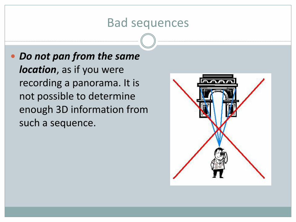
Do not pan from the same location, as if you were recording a panorama. It is not possible to determine enough 3D information from such a sequence.
Bad sequences (2)
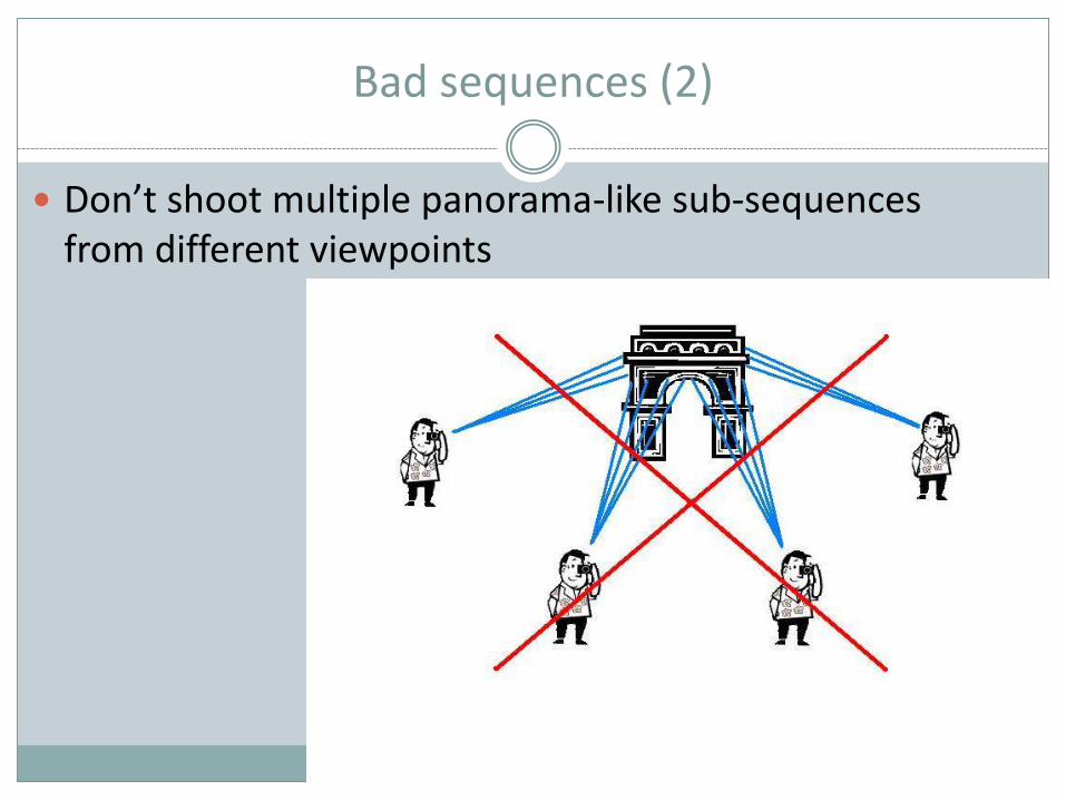
Don’t shoot multiple panorama-like sub-sequences from different viewpoints
Bad sequences (3)
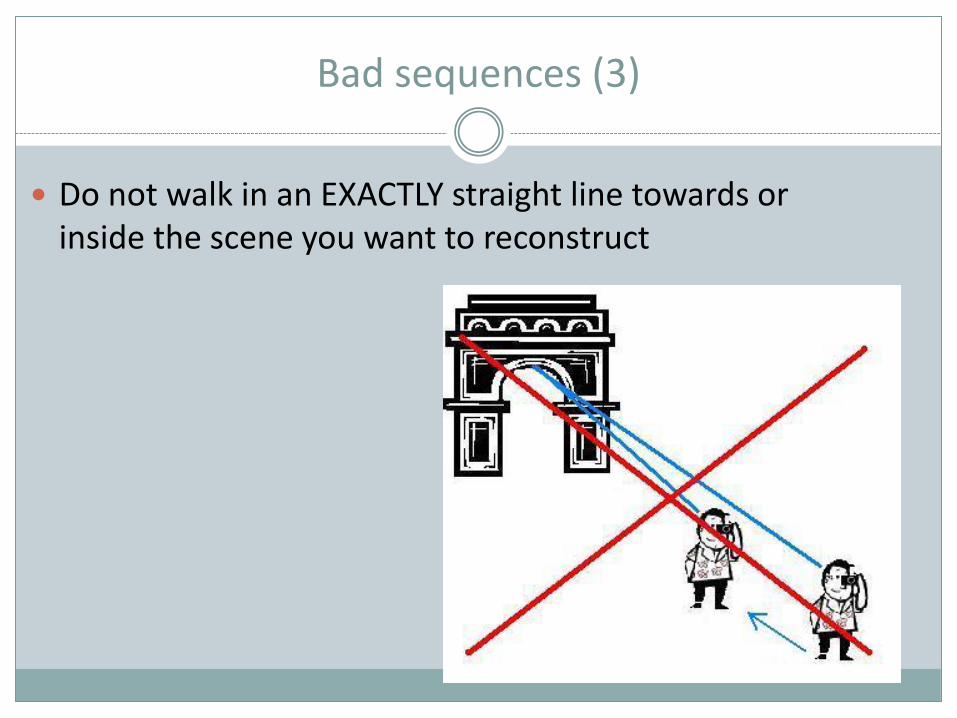
Do not walk in an EXACTLY straight line towards or inside the scene you want to reconstruct
Good sequence
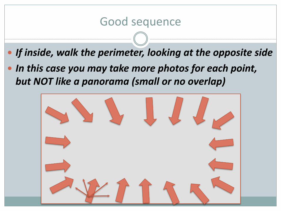
If inside, walk the perimeter, looking at the opposite side
In this case you may take more photos for each point, but NOT like a panorama (small or no overlap)
Good sequence
Shoot from different heights... This helps a lot
You can mix photos taken at different distances: i.e. shoot the whole object going around, then get closer and cover the object again framing smaller areas, then get closer again and frame details
Background is important!!!!
Bad sequences (4)
It is better to shoot a lot of pictures than few ones.
The viewing angle between images should not be too large, i.e. adjacent images should not be too far apart
Consider 15-20 degree as a good step...
Bad sequences (5)
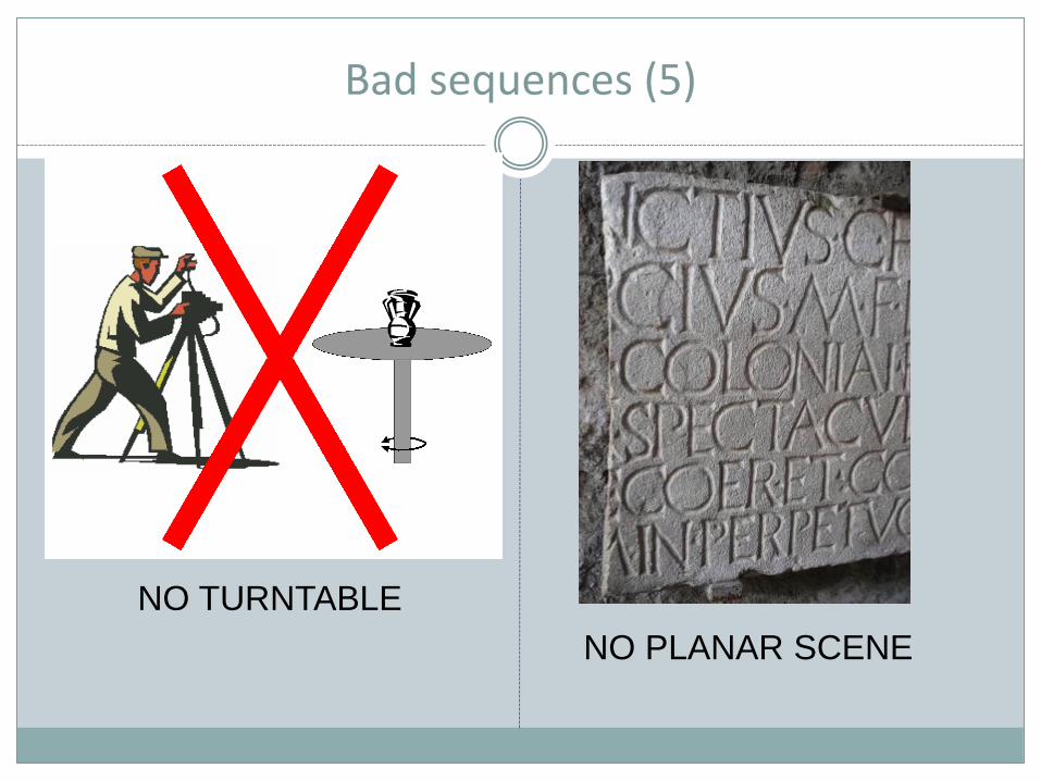
NO TURNTABLE
NO PLANAR SCENE
Practical Problems
All information is retrieved from the images, so take care when you shoot them!
The texture (color, intensity) of the scene/object is critical!
Enough texture must be available on the object
Appearance of object must stay the same!
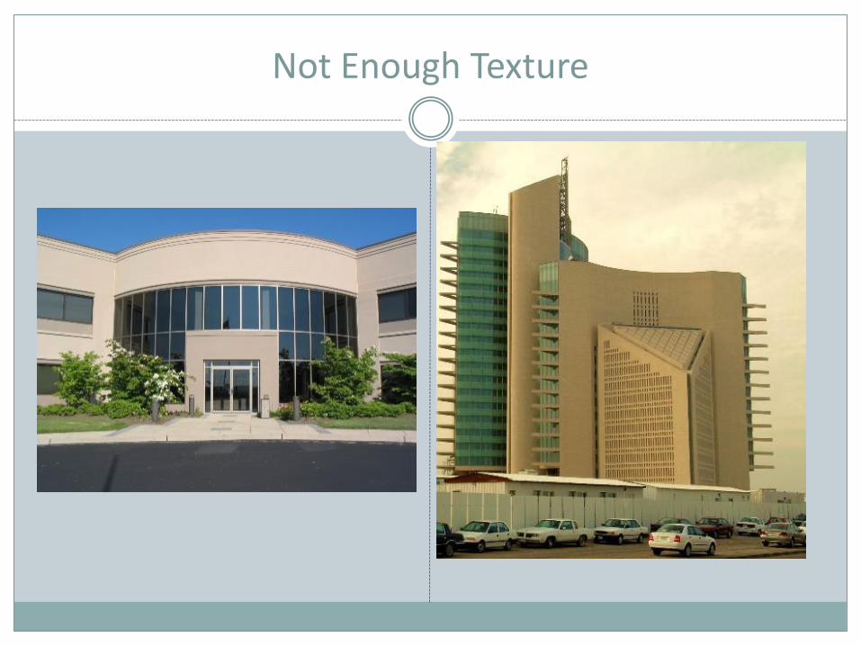
Not Enough Texture
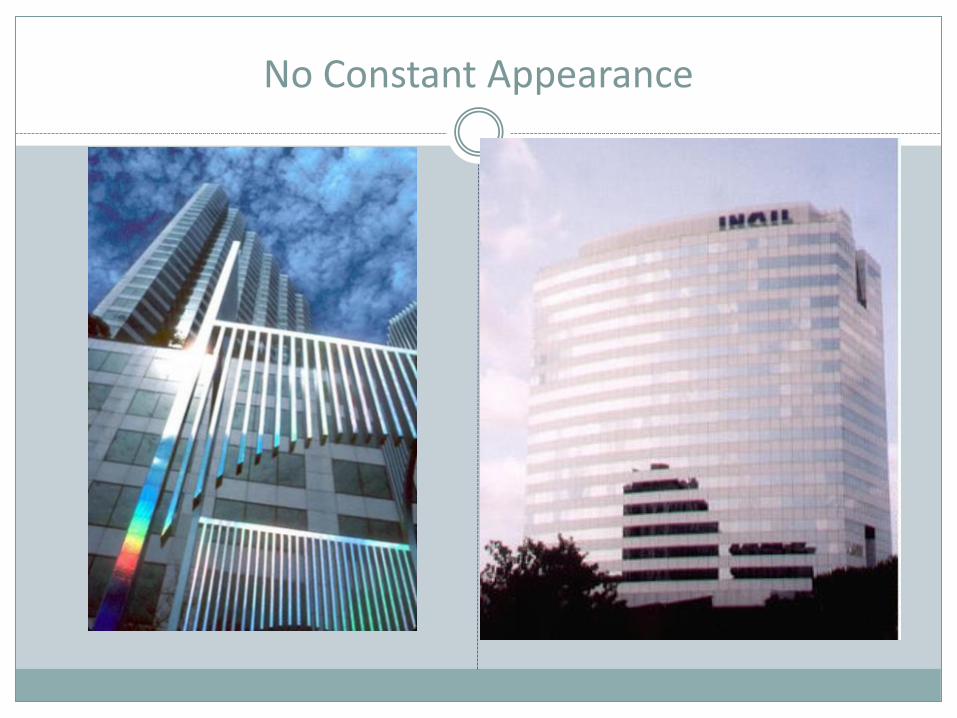
No Constant Appearance
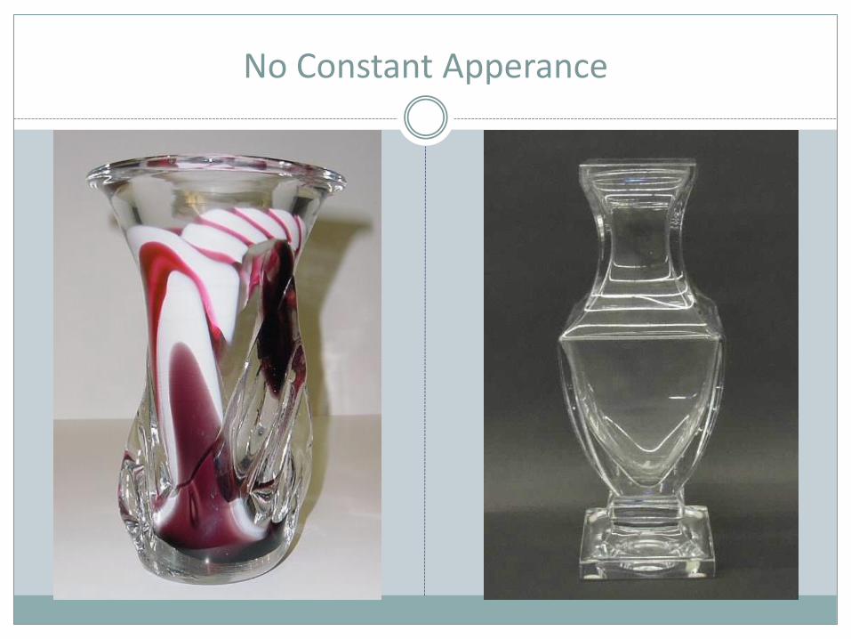
No Constant Apperance
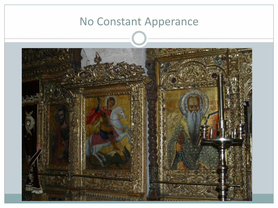
No Constant Apperance
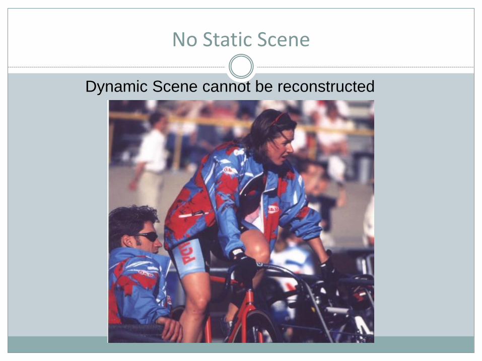
No Static Scene
Dynamic Scene cannot be reconstructed
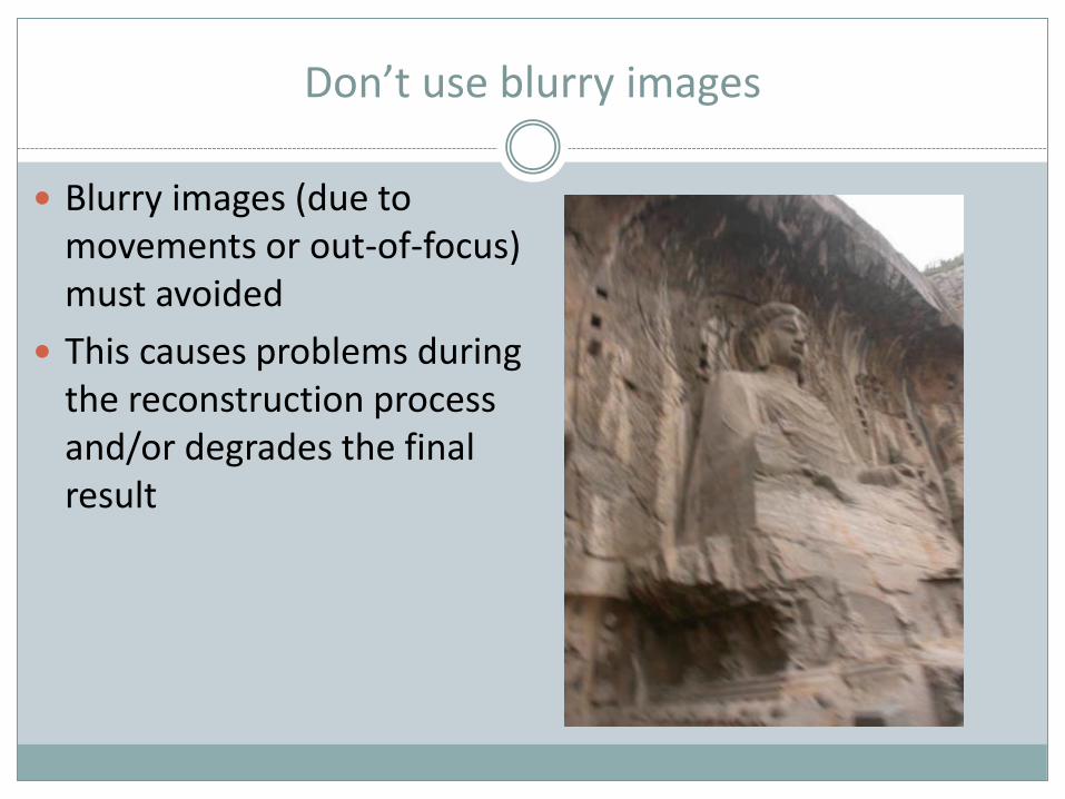
Don’t use blurry images
Blurry images (due to movements or out-of-focus) must avoided
This causes problems during the reconstruction process and/or degrades the final result
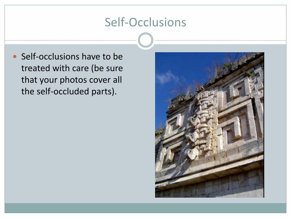
Self-Occlusions
Self-occlusions have to be treated with care (be sure that your photos cover all the self-occluded parts).
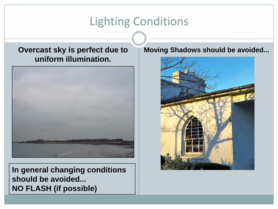
Lighting Conditions
Moving Shadows should be avoided...Overcast sky is perfect due to
uniform illumination.
In general changing conditions
should be avoided...
NO FLASH (if possible)