3d geologic framework models for regional hydrogeology and land-use management: a case study from a...
TRANSCRIPT

3D geologic framework models for regional hydrogeologyand land-use management: a case study from a Quaternary basinof southwestern Quebec, Canada
Martin Ross · Michel Parent · Ren� Lefebvre
Abstract During a regional hydrogeologic survey in theSt. Lawrence Lowlands, Canada, a computer-based 3DGeologic Framework Model (GFM) was constructed toobtain a consistent representation of this typical Quater-nary glaciated basin over a 1,400 km2 area. Such a de-tailed stratigraphic reconstruction was needed because theQuaternary sediments control the recharge to the under-lying regional fractured rock aquifer and also becauseburied granular aquifers are partly connected to the re-gional system. The objectives of this geomodeling effortare 1) to improve understanding of subsurface conditionsabove the regional aquifer and; 2) to provide a commonstratigraphic framework for hydrogeologic applications.The method draws on knowledge-driven discrete model-ing using gOcad, as well as standardization and qualitycontrol procedures to maximize the use of a multisourcedatabase. The resulting model represents the bedrock to-pography and the complex stratigraphic architecture ofoverlying sediments. The regional till aquitard, the marineclay aquiclude and the buried granular aquifers have beenmodeled with unprecedented details thus providing awell-constrained 3D hydrostratigraphic framework. Therecharge zones of the rock aquifer represent about 35%of the study area. Buried granular aquifers are directlyconnected to the regional aquifer system over about 10%of the area. The model allows several applications such asassessing aquifer vulnerability and areal groundwater re-charge rates; improving the GFM inter-operability withgroundwater modeling systems would be the next logicalstep.
Resumen Se construy� un Modelo del Marco Geol�gico(GFM) 3D basado en computadora durante un levanta-miento hidrogeol�gico regional en las Tierras Bajas de St.Lawrence, Canada para obtener una representaci�n con-sistente de esta cuenca glaciar Cuaternaria t�pica en un�rea de 1,400 km2. Se necesit� tal grado de reconstrucci�nestratigr�fica debido a que los sedimentos Cuaternarioscontrolan la recarga del acu�fero rocoso fracturado re-gional subyacente y tambi�n porque los acu�feros granu-lares enterrados est�n parcialmente conectados con elsistema regional. Los objetivos de este esfuerzo de mo-delizado geol�gico son: 1) mejorar el entendimiento delas condiciones subsuperficiales por encima del acu�feroregional y; 2) aportar un marco estratigr�fico comffln paraaplicaciones hidrogeol�gicas. El m�todo se basa en elconocimiento de modelizado discreto utilizando gOcad,as� como tambi�n en estandarizaci�n y procedimientos decontrol de calidad para maximizar el uso de bancos dedatos de fuentes mfflltiples. El modelo obtenido representala topograf�a del macizo rocoso y la arquitectura de lacompleja estratigraf�a de los sedimentos sobreyacentes. Elacuitardo regional de tillita, el acuicludo arcilloso marinoy los acu�feros granulares enterrados se han modelizadocon detalles sin precedentes aportando de este modo unmarco hidroestratigr�fico 3D bien definido. Las zonas derecarga del acu�fero rocoso representan casi el 35% del�rea de estudio. Los acu�feros granulares enterrados est�nconectados directamente al sistema acu�fero regional so-bre aproximadamente el 10% del �rea. El modelo permitevarias aplicaciones tal como evaluar la vulnerabilidad deacu�feros y ritmos de recarga areales de agua subterr�nea;el paso l�gico siguiente ser�a mejorar la inter-operabilidaddel GFM con los sistemas de modelizado de agua sub-terr�nea.
R�sum� Dans le cadre d’une �tude d’hydrog�ologie r�-gionale dans les basses terres du Saint-Laurent (Canada),un Mod�le surfacique g�ologique en 3D (MSG) a �t�d�velopp� pour obtenir une repr�sentation coh�rente parordinateur de ce bassin quaternaire sur une superficiede plus de 1,400 km2. Une telle reconstitution stratigra-phique �tait n�cessaire en raison du contr�le qu’exercentles s�diments quaternaires sur la recharge de l’aquif�rer�gional fractur� sous-jacent et aussi parce que les aqui-f�res granulaires enfouis sont partiellement connect�s ausyst�me r�gional. Les objectifs de cet effort de g�omo-
Received: 25 July 2003 / Accepted: 31 May 2004Published online: 3 August 2004
� Springer-Verlag 2004
M. Ross ()) · R. LefebvreInstitut National de la Recherche Scientifique (INRS-ETE),880 chemin Sainte-Foy, bur. 840, C.P. 7500, Qu�bec (Qc.),G1V 4C7, Canadae-mail: [email protected].: +418-654-3161Fax: +418-654-2615
M. ParentGeological Survey of Canada,880 chemin Sainte-Foy, Suite 840, Qu�bec (Qc.), G1S 2L2, Canada
Hydrogeology Journal (2005) 13:690–707 DOI 10.1007/s10040-004-0365-x

d�lisation sont: 1) d’am�liorer la compr�hension desconditions de sous-surface au-dessus de l’aquif�re r�gio-nal et; 2) de fournir un cadre stratigraphique commun des fins de caract�risation hydrog�ologique. La m�thoderepose sur l’int�gration de l’interpr�tation g�ologiquedans la mod�lisation discr�te effectu�e l’aide du logicielgOcad, ainsi que sur des proc�dures d’uniformisation etde contr�le de la qualit� des donn�es afin d’optimiserl’utilisation d’une base de donn�es multisources. Le MSGrepr�sente la topographie du roc et l’architecture strati-graphique des s�diments sus-jacents. L’aquitard r�gional(till), l’aquiclude d’argile marine et les aquif�res granu-laires ont �t� mod�lis�s un niveau de d�tail sans pr�-c�dent, fournissant ainsi un cadre hydrostratigraphiquesolidement �tabli. Les zones de recharge de l’aquif�rerocheux repr�sentent environ 35% de la zone d’�tude. Lesaquif�res granulaires enfouis sont connect�s directementau syst�me aquif�re r�gional sur au moins 10% du terri-toire. Le MSG permet de multiples usages tels l’�valua-tion de la vuln�rabilit� des aquif�res et l’estimation de ladistribution de la recharge; la prochaine �tape logiqueserait l’am�lioration de l’interop�rabilit� avec les sys-t�mes de mod�lisation num�rique de l’�coulement.
Keywords 3D geological models · Spatial database ·Hydrogeology · Quaternary · St. Lawrence Lowlands
Introduction
In recent years, Quaternary deposits of northern US andCanada have been used for an increasing number of hu-man activities, such as sand mining and for waste disposaland water supply, which are known for their potentialimpact on groundwater. Moreover, it has become apparentthat understanding relationships between Quaternary de-posits and groundwater is also a necessity in areas wheremost water supplies come from bedrock aquifers. Indeed,these deposits are frequently a major factor controllingconfining conditions and recharge of bedrock aquifers.This situation has highlighted the urgency to improvingknowledge of hydrogeologic settings of glaciated terrainsin rapidly developing regions. However, delineating con-fining layers and sub-surface aquifers and aquitards inthese complex settings is by no means a trivial task and aclose integration of stratigraphic reconstructions and hy-drogeologic applications still represents a significant chal-lenge.
An important difficulty in regional hydrogeologic sur-veys is to have access to sole-sourced consistent geolog-ical information which can accommodate many specificneeds. A solution may be to create a computer-based“repository” of the stratigraphic knowledge of the studyarea (Mallet 2003) which is common to all project teammembers as opposed to a common practice in which ge-ologic information is stored on different media and dis-persed through a series of independent end-products. Thisapproach reduces redundancy and risks of inconsistenciesand helps to streamline updating procedures. An obvious
benefit is that it does away with the necessity of redoingmuch of the interpretation and stratigraphic modeling toadjust to the specific requirements of various applications;in the end, time savings can be huge.
In recent years it has become technologically feasibleto build in a reasonable time frame complex 3D geologicor hydrostratigraphic models, to incorporate and analyzetheir properties and to export the information to othersoftware systems to meet the specific requirements of anapplication. This has opened a new perspective in hy-drogeology where a number of applications require thatall the available hydrogeological information be incor-porated into a full three-dimensional conceptual model(e.g., Frind et al. 2002). Consequently, producing suchcomputer-based geologic models is becoming an impor-tant objective in many hydrogeologic surveys. For in-stance, the Geological Survey of Canada (GSC) has in-tegrated some aspects of 3D modeling in its hydrogeo-logic investigations since the mid 90s (Sharpe et al. 1996;Parent et al. 1998; Ricketts 2000; Girard 2001; Loganet al. 2001; Thorleifson et al. 2001; Ross et al. 2002).Also, US federal and state agencies have developed 3Dmapping programs for regional hydrogeologic studies(Belcher et al. 2002; Herzog et al. 2003), hydrogeologiccharacterization of underground nuclear test areas (USDepartment of Energy 1997) and radioactive waste re-pository (Clayton 2000), and for land-use planning andmanagement (Soller et al. 1999; Berg et al. 2000). Effortsare also carried out elsewhere such as in Finland (Artimoet al. 2003). However, regional 3D models and associatedmultiple usages are still uncommon due to organizationaland resource constraints as well as to problems related todata quality, quantity and distribution. Furthermore, eventhough many approaches are conceivable for the devel-opment of 3D models, they are not necessarily suitable forevery field situation or survey objective. Therefore, theprocedures developed to construct 3D geologic or hy-drostratigraphic models must adapt to project objectivesbut the resulting models should have the level of strati-graphic details required by the most demanding applica-tion.
The work presented in this paper is part of a regionalhydrogeologic investigation carried out by the GeologicalSurvey of Canada (Savard et al. 2000). The study area islocated in the St. Lawrence Lowlands near Montreal(Fig. 1), a rapidly developing region where groundwaterconservation has become a public issue. The objectives ofthis work are to: 1) improve understanding of subsurfaceconditions above the regional fractured rock aquifer and;2) to provide a common framework for different hydro-geologic applications. To achieve these goals, a strategyhas been developed to create a computer-based 3D modelof the regional bedrock topography and overlying Qua-ternary stratigraphic architecture (Geologic FrameworkModel, GFM). This paper thus presents the strategy itself,the resulting 3D model as well as a few applications. TheGFM is used to describe the main Quaternary hydrogeo-logical settings. Also provided are brief descriptions ofhow the model was used to assess aquifer vulnerability to
691
Hydrogeology Journal (2005) 13:690–707 DOI 10.1007/s10040-004-0365-x

contamination (Ross et al. 2003) and, to some extent, tocalibrate the regional numerical model (Nastev et al. inreview, a). Other potential applications are suggested. Themain challenge for 3D modeling in such a setting stemsfrom the discontinuous nature of the units, their highlyvariable thickness and the fact that most units are onlypartly exposed at the surface. The procedure applied toconstruct the GFM takes advantage of the capabilities ofmodern geomodeling systems, basin analysis techniques(Miall 1992) and quality control as well as standardizedprocedures to optimize the use of a multisource database.
Characteristics of the Study Area
The study area extends over about 1,500 km2 between theLaurentian Highlands, the Ottawa River and other St.Lawrence River tributaries (Fig. 1). At low elevations,ranging from 25 m above sea level (masl) up to about70 masl, the region mainly consists of a low-relief clayplain incised by paleochannels of the Ottawa River and bymodern rivers and streams. At higher elevations, from70 m to 95 m, it consists of a drumlinized till plain whichrepresents important groundwater divides and rechargeareas. Both zones mainly trend northeast-southwest, par-allel to the nearby Shield margin (Laurentians). Eleva-tions rise to 250 masl in a large Shield inlier, the OkaHills. The rural and semi-rural population depends largelyon fractured-rock aquifers for water supply and the regionis undergoing rapid housing development due to itsproximity to Montreal.
The bedrock is essentially made of Paleozoic sedi-mentary rocks of the St. Lawrence Lowlands Platformwhich locally consists of a 1,500 to 3,000-m-thick suc-cession of sandstones and carbonates ranging from Cam-brian to Middle Ordovician (Globensky 1987). Theserocks are underlain by a Precambrian basement which
outcrops in the Laurentian Highlands as well as in twohills (St. Andr� and Oka) which also contain Cretaceousintrusive rocks (carbonatites). Bedrock is overlain by adiscontinuous cover of Quaternary sediments reaching upto 150 m in thickness and offering a great variety of hy-drogeologic settings. The Quaternary geology of the studyarea has been described and interpreted by Hillaire-Marcel(1974), Prichonnet (1977) and L�vesque (1982), and morerecently by Bolduc and Ross (2000) as well as Ross et al.(2001). Over 200 stratigraphic boreholes reaching bedrockwere also drilled in the early 1970s to support decision-making for the location of the Mirabel International Air-port (Kugler-Gagnon 1974; St-Onge 1979). The Quater-nary sequence mainly comprises Late Wisconsinan sub-glacial (20–12 ka), proglacial (12–10 ka) and Holocene(<10 ka) postglacial sediments forming discontinuousunits of variable thickness. Till and Champlain Sea clayare the most widespread units.
The regional aquifer system is largely confined andmainly consists of fractured sedimentary rocks. In addi-tion, some overlying discontinuous units of permeableQuaternary sediments are connected to the fractured rockaquifer in some parts of the study area and contribute tothe regional system. These granular aquifers are mainlymade of ice-contact glaciofluvial sand and gravel andproglacial sand. The uppermost part of the fractured rockaquifer was found to be more permeable than rock layersat greater depth (Nastev et al. 2001). Confining of theaquifer units is provided by the till and the marine claywhich act respectively as regional aquitard and aquiclude.Regressive sands commonly overlie marine clay thusforming an upper unconfined aquifer of variable extent.Therefore, the Quaternary succession largely controls theconfining conditions of the regional aquifer as well as itsrecharge which occurs on topographic highs where bed-rock either crops out or is covered by thin discontinuoustill. More details can be found concerning aquifer prop-
Fig. 1 Location of study areawith digital elevation model asbackground. Locations of somefigures in the text are alsoshown
692
Hydrogeology Journal (2005) 13:690–707 DOI 10.1007/s10040-004-0365-x

erties in Nastev et al. (2001 and in review, b), hydro-geochemistry in Cloutier et al. (2001), and rechargecharacteristics in Hamel et al. (2001).
Method
Data AcquisitionConsiderable field work was carried out between 1999and 2001, including surficial mapping, detailed geologicsection analyses, stratigraphic drilling, ground penetratingradar (GPR) and shallow seismic reflection surveys. Twomaps of the Quaternary geology were completed at ascale of 1:50,000 (Bolduc and Ross 2001a, 2001b), thedistribution of most of the newly-acquired subsurface dataused for constructing the model are shown in Fig. 2. Highresolution shallow seismic data acquisition and process-ing are described by Benjumea et al. (2001) while theirpreliminary interpretation was presented by Ross et al.(2001).
Archival Data Quality Control and StandardizationGeologic and hydrogeologic data were integrated in adatabase (Accesstm Microsoft 1997). The database struc-ture is described by Boisvert and Michaud (1998). Allrecords in the database are spatially referenced by UTMcoordinates and most by elevation. The database is largelycomposed of archival boreholes from the provincial da-tabase (Hydrogeologic Information System (HIS); http://www.menv.gouv.qc.ca/eau/souterraines/sih/index.htm.This database was first assembled in the 70s by theQu�bec Ministry of Environment to integrate in digitalformat water well logs and geotechnical boreholes fromseveral public agencies. The Ministry has carried outlocation checks in the field between 1980 and 1985 as
well as some automatic verifications such as comparingborehole depth with calculated lithologic thickness toconfirm data consistency (R. Perron personal communi-cation — 2000). The HIS database has been updatedperiodically.
Newly acquired data and boreholes from other sourceswere added, such as recent geotechnical boreholes fromprivate firms, and 417 well locations were verified in thefield. Data for a total of 5,148 boreholes were compiledfor the study area. Since the subsurface data are ofvariable reliability, they were assigned a weighting factorusing a step-by-step data management approach, whichinclude data documentation and quality control proce-dures. The criteria are listed in Table 1. Database qualitycontrol was initiated using MapInfo 5.0 (MapInfo) toidentify potentially anomalous data. Since the automaticfactor attribution is only a preliminary step, no data weredeleted during this procedure; it was used to flag po-tentially anomalous data. The archival surface elevationof each borehole was then compared to a Digital Eleva-tion Model (DEM). Where differences of 10 m or morewere encountered, the record was assigned a reliabilityfactor of 2 (Table 1). Boreholes located over lakes awayfrom shorelines were assigned a factor of 1 and thoselocated more than 500 m away from any human infra-structure such as a building or road were assigned afactor of 2. Other validation steps were needed after thisinitial quality control procedure (see below; Buildingcross sections), before considering acceptance/rejectionof these data.
The next step was to identify boreholes described us-ing accepted scientific methodology and for which theoriginal documentation was available. These documentswere compared with their digital equivalent during qual-ity control procedures and corrections were applied whenneeded. After completion, these data were assigned a
Fig. 2 Distribution of newly-acquired data and the most re-liable archival boreholes (seeTable 1). Note that reliable dataare scarce in the westernmostpart of the study area
693
Hydrogeology Journal (2005) 13:690–707 DOI 10.1007/s10040-004-0365-x

factor of 4, or 5 if samples were available. Their distri-bution is shown in Fig. 2. All other data were assigned apreliminary value of 3. As can be seen from Fig. 2, themost reliable data are exceptionally well distributed. It is
also important to note that 68% of all the boreholes in thedatabase reach bedrock, thus, offering unusually favor-able conditions for constructing a regional GFM of theQuaternary stratigraphy and bedrock topography.
A standard code has been developed (Parent et al.2003) to integrate data that have different descriptive at-tributes. The purpose of the code is to group attributeswhich are related to a similar lithology. It is important tonote that the standardization added a new classification,which means that the old ones were preserved. An ex-ample of standardization is shown in Fig. 3. This abridgedcode is especially useful and facilitates correlation be-tween highly detailed descriptions using lithofacies codeand non-standardized poorly detailed descriptions.
The Geologic Framework Model (GFM)
The Choice of the Modeling ToolGIS are modern powerful tools which allow for spatialanalyses and representations of georeferenced data(Bonham-Carter 2000). These tools have proved theirusefulness in hydrogeology over the years but standardmulti-layered systems are quite limited for modeling,visualizing and editing subsurface data and geologic ob-jects and their attributes. With these general-purpose GIS,geologic layers are represented as regular grids or trian-gulated surfaces which can only be modeled as explicitfunctions z=f(x,y). The topology and geometry are at bestin 2.5D (a dimension characterizing non-planar surfacesembedded in 3D space) and thus cannot integrate all theconstraints induced by 3D data sets. However, in recentyears geomodeling systems have been developed withhigh 3D visualization, geometric as well as propertymodeling capabilities to enable the construction andanalysis of 3D geologic models in a way that general-purpose GIS and CAD systems simply cannot do (e.g.,Mallet 1992, 2002). In the perspective of increasing inter-operability between databases and these modeling tools(e.g., Breunig 1999) as well as with end-process tech-nology, these capabilities open a new perspective forhydrogeological applications. An exhaustive presentationof the evolution of concepts and description of methodscurrently used in 3D geologic modeling is however be-yond the scope of this paper. The reader is thus referred toa few textbooks, papers or reports (Raper 1989; Turner
Table 1 Borehole database validation criteria
Reliabilityfactor
Reliability Criterion Data type
5 High Original logs and reports are available for checkingprocedures. Samples are available
Stratigraphic, geotechnical boreholes andwater wells described using acceptedscientific methods
4 Good Original logs and reports are available. Some welllocations have been verified in the field
3 Fair Original logs are not available. There is no apparentinconsistency with nearby reliable data
Geotechnical boreholes and water wells
2 Low One problem; anomalous location or stratigraphic log Water wells1 Bad Multiple problems Water wells
Fig. 3 Stratigraphic logs providing an example of the standardcode which was implemented to facilitate correlation betweenhighly detailed descriptions using lithofacies code (e.g., Eyles et al.1983) and non-standardized poorly detailed descriptions. Thisabridged code is particularly useful when systematic distinctions,such as coarse/fine sand, are needed
694
Hydrogeology Journal (2005) 13:690–707 DOI 10.1007/s10040-004-0365-x

1992; Pflug and Harbaugh 1992; Hamilton and Jones1992; Houlding 1994; Alms et al. 1996; BRGM 1997;Jessell 2001; Courrioux et al. 2001; Mallet 2002).
A discrete modeling approach was chosen to constructthe geologic model. The 3D geomodeling system gOcad(Earth Decision Sciences 2001) was used on a PC with aWindows 2000 (Microsoft) platform to carry out this partof the work. This software, which is being developed bythe gOcad Research Group at the Nancy School of Ge-ology (France) and its partners, is specifically designed toconstruct and analyze geologic objects and their proper-ties (Mallet 1992). This tool is mainly developed for ap-plications in the petroleum industry, although it is in-creasingly used in the geosciences in general.
A complete presentation of the notion of discretemodeling is made by Mallet (2002). With this approach,discrete triangulated surfaces can be built from points,lines, open and closed curves and be modified by apply-ing the Discrete Smooth Interpolation (DSI) algorithm(Mallet 1989; Mallet 2002) which minimizes a roughnesscriterion while honoring any linear hard and soft con-straints. For example, DSI can be applied to smooth asurface while honoring exactly some of the control pointsand only to some degree other less reliable data as well astaking into account thickness constraints along a specifieddirection. With this modeling approach, a 3D model isprimarily defined by a series of interlocking surfacesrepresenting the boundaries of geological objects. Thespace can then be consistently partitioned to describe andrepresent the geological objects as 3D regions. In thispaper, such models are referred to as Geological Frame-work Models (GFM). One of the main benefits of usingthis approach is that it can provide a detailed definition ofthe stratigraphic architecture without depending on anyspecific high-resolution 3D grid. This is a critical pointsince a detailed GFM can be used without any internalmesh or as the backbone for further discretization whosetype and resolution are adapted to fit the specific needs ofany particular application (geostatistics, groundwater flowsimulation, etc.).
Building Geologic Cross SectionsPrior to the construction of the model surfaces, one of themost challenging aspect of the modeling task was to ad-equately correlate borehole attributes to a given strati-graphic unit. In Quaternary basins, units are frequentlythin and discontinuous and similar facies can be found indifferent unconnected units. Tills are especially hard torecognize in a multisource database because the use of theterm “till” is not generalized and the lithological de-scription is often incomplete or even erroneous such thatthey may be incorrectly assigned to another sediment typeand, thus, to another unit. Therefore, assigning a lithologyto a specific unit automatically by querying a databasewill provide results of limited use or validity. Any auto-matic or semi-automatic data standardization and valida-tion method, including the one described in this paper (seeabove), must be done in combination with knowledge-
driven tools such as basin analysis and facies models tohelp identify data which should be considered as beingpart of the same geologic body and to guide the bridgingbetween data points. Since the known composite strati-graphic sequence is usually incomplete at most sites,correlations must be made carefully. Since it is morenatural and easier for the human mind to understand datarelationships in 2D, the initial correlation and interpola-tion were made using 2D vertical working planes. How-ever, following the work of Ragan (1985), Marschallinger(1991) and Schetselaar (1995), it was decided to buildgeologic cross sections directly in the 3D graphic andgeoreferenced environment. This approach helped to re-duce data transfers and one can use the 3D visualizationcapabilities to interactively test the consistency of anewly-built cross section with the others in a georefer-enced environment common to all input data. More than40 cross sections were built this way to form the basis ofthe 3D framework. Their location is shown in Fig. 4a.Except for two of them, they are aligned perpendicular tothe main regional geologic structures and forms.
Boreholes were initially grouped in different collec-tions according to their source in order to facilitate datavisualization in highly clustered areas. Cross sectionbuilding started prior to the decision of using gOcad asthe geomodeling tool in the project and a macro commandwas used to draw boreholes in Microstation (Bentley)which is a CAD software offering 3D modeling and vi-sualization capabilities. The link with Access (Microsoft)was provided using an Open Database Connectivity(ODBC). Every other relevant piece of information wasimported into Microstation such as vector maps repre-senting topography, hydrology, geology, roads, etc. Atriangular irregular network (TIN) was created from to-pographic data and every piece of surface informationwas draped onto that TIN. The cross sections which werebuild along 2D working planes integrate all reliablesubsurface and surface data within a 1–2 km wide strip.These curves were subsequently exported as DXF filesinto gOcad in order to be used later as geometrical con-straints in the 3D model. However, it is important to notethat, since gOcad was later chosen as the 3D geomodelingsystem (see above), the use of Microstation was aban-doned and all data were directly transferred to gOcadfrom databases and GIS packages via ASCII (*.txt),Shape (*.shp) or DXF (*.dxf) files using built-in “filters”.This has reduced software interplay and streamlined theprocedure for future projects. The last cross sections weredirectly built in gOcad using interactive tools. Vertical 2Dworking planes (surfaces) were built and only those datawhich are located inside the 1–2 km wide zone are set asvisible in the 3D camera using a “slicer” tool (Fig. 4b).The boundaries of geologic objects are built on theworking planes using curve editing tools.
Such cross sections can be regarded as a type of in-telligent interpolation and extrapolation method. Here,this method is not only intended to provide interpreta-tional control to the 3D model but also to provide expertconstraints on data quality control and correlation.
695
Hydrogeology Journal (2005) 13:690–707 DOI 10.1007/s10040-004-0365-x

A schematic example of the data validation and cor-relation method is given in Fig. 5. Correlations were madebetween reliable data through expert knowledge (e.g. fa-cies models and relationships, geologic rules). Particularattention was given to data considered anomalous afterthe automatic validation procedure previously describedand corrections were applied to reliability factors whenneeded. The “less reliable” data (factor 3) were usuallyintegrated while the remaining data with factors 1 and 2
were partly considered as guidelines if, and only if, therewas no other subsurface information in the vicinity. Thoseareas constitute priority targets for further investigation.
Surface ModelingThe overall workflow of surface construction as well asother steps in the modeling procedure are presented inFig. 6. The surfaces can be built first with non-standard-
Fig. 4 a Location of regionalcross sections in plan view. bExample of the 3D graphic en-vironment in which cross sec-tions are built. The white inter-locked curves represent the topof each unit along the crosssection. These curves are usedas constraints during the subse-quent surface modeling
696
Hydrogeology Journal (2005) 13:690–707 DOI 10.1007/s10040-004-0365-x

ized borehole data to provide quick maps in support ofdecision-making in the early stages of an investigationand be modified as validation results and new data be-come available (geological maps, new boreholes, geo-physical data, cross sections). As more data are added,evaluated and corrected, the surfaces are better con-strained and become increasingly accurate. Once crosssections and data validation procedures are completed,new surfaces are built to provide a final model withmaximum geological consistency and to make sure thereare no remaining artifacts related to earlier versions of themodel. Cross section curves and geological map contactsare used here as the main expert knowledge constraints(cf., Fig. 4b) but other constraints were also applied totake into account reliable data between cross sections inorder to increase the accuracy of interpolated surfaces.These include topographic data, small outcrops, curvesfrom interpreted seismic profiles and contacts from bore-holes with reliability factor of 4 or 5.
Since building surfaces separately does not ensure thatthey are consistently in the correct stratigraphic orderaway from cross sections, increased mesh density andminimum thickness constraints were applied locally toremove most crossovers which are frequent where unitsare thin, especially if the variability of the top elevation ofa unit is larger than its thickness. The remaining cross-overs were removed manually by adjusting triangle nodesbut in many cases, discontinuities were created. Specialattention was also given to reliable boreholes that do notreach bedrock in order to respect minimum thicknessconstraints using interactive tools. Crossovers and otherthickness problems were thus corrected locally dependingon the specific problem instead of taking a referencesurface, calculating its thickness and then adjusting all the
others to fit that layer. Therefore, surfaces are not re-gionally modified on the basis of a reference layer asopposed to what is often done in multi-layered modelingusing standard GIS tools.
Model VolumesThe interlocked surfaces are intended to form closedvolumes representing geologic bodies. The surfaces thusact as “dividing walls” isolating 3D regions (Mallet2002). However, the partitioning of the subsurface intosuch 3D regions which describe the topological spacerequires that the surfaces be “welded” together. It istherefore critical that the topology defined by the surfacesbe unambiguous. Surfaces must form a closed volume andthe line defined by the intersection of two surfaces mustbe unique and free of gaps. Time-consuming operationsmay be required to achieve this goal in complex modelswhich have numerous and highly detailed intersectingsurface borders. However, this is very useful to make surethat topology is consistent as this allows calculation ofvolumes, visualization of separated objects and applica-tion of grid generation tools that maintain the geometricintegrity of the GFM. In order to achieve this, manyimprovements were applied along surface intersections.Further discretization was also applied using advancedgridding tools that allow the construction of curvilinearregular 3D grids which conform to the stratigraphic ar-chitecture. The 3D regions and grids were used to createsub-models for geologic setting visualization, to generatecontinuous units for groundwater flow modeling as wellas to calculate unit thickness and volumes. The grids werealso used in parameter estimations for aquifer vulnera-bility mapping (see below).
Fig. 5 Schematic exampleshowing how cross sectionbuilding was used for dataquality control and correlation.Note the different lithologicdescriptions for the till uniteven using standard code. Clearidentification of this unit wassometimes difficult which re-sulted in some ambiguous cor-relations between borehole data,especially in areas whereglaciofluvial and proglacialsediments are likely present atdepth. Cross section buildingwas however very helpful insolving many such problems
697
Hydrogeology Journal (2005) 13:690–707 DOI 10.1007/s10040-004-0365-x

Results
A compilation of data and their associated reliability factor(Table 2) shows that only 40% of the database was usedfor constructing the GFM. This does not mean howeverthat 60% of the boreholes are unreliable. In fact, manyconsistent data (factor 3) were not needed, such as inclustered areas where there were sufficient reliable bore-holes (factor 4 and 5) to construct the GFM. The GFM isshown in Fig. 7. The GFM is made of interlocked surfacesrepresenting the top of bedrock (Fig. 7a) and each of themain Quaternary units recognized in the study area. Someunits are only partly represented in the Oka Hills and inthe Laurentian Highlands (Fig. 7e); lag deposits less than
1 m thick are generally not included. Units older than theregional till are represented together as a single discon-tinuous top surface (Fig. 7a) since data regarding thoseunits were too scarce to allow more details. Two super-posed till units were found during field investigations butsince the lower till could be observed in only one boreholeand traced confidently along a single seismic line, it wasnot possible to represent them separately at a regionalscale. Ice-contact glaciofluvial and proglacial outwashdeposits were also combined to form one top surface(Fig. 7b). Special attention was given to the discontinuitiesin the marine clay aquiclude (Fig. 7c). Holocene regres-sive sands were modeled as separate surfaces according totheir origin (Fig. 7d) with the exception of aeolian deposits
Fig. 6 The model constructionprocedure is a step-by-stepworkflow designed to supportscientific reasoning and deci-sion-making during an ongoingproject. Note that preliminaryoutputs are available in earlystages of the survey. Thisstratigraphic reconstructionprocedure is most amenable tomultiple usages
698
Hydrogeology Journal (2005) 13:690–707 DOI 10.1007/s10040-004-0365-x

which were grouped with their parent sediments. Also,organic deposits are not included in the model.
Corrections were needed to improve geological realismin areas such as steep terraces or along pinchouts. Al-though the model top view (Fig. 7e) closely matches thesurficial geology maps of Bolduc and Ross (2001a, 2001b)it is not identical since the level of map detail is too highand some geologic bodies, such as small beaches, are toosmall and numerous to be included in the 3D model. Forthis reason, surface borders do not honor exactly geolog-ical map contacts. Corrections were also needed on a fewcross sections and even on the geologic maps since some
internal consistency problems were only recognized dur-ing 3D modeling. Field verifications were carried out toconfirm most changes made to geological maps.
The bedrock surface shows much more relief than theoverlying land surface (Fig. 7). Hence Quaternary depositthickness tends to increase where bedrock elevation de-creases, as shown in Fig. 8, thus forming buried depres-sions. These SW-trending, deep and narrow buried val-leys were successfully modeled, thus offering a consistentgeomorphology which is very difficult to obtain usingapproaches that are not knowledge-based.
Fig. 7a–e The 3D geologicframework model (GFM). Notethat model is incomplete in theOka Hills. It is depicting com-plex geomorphology and strati-graphic architecture. It containsnarrow channelized features(e.g. b) and most units arehighly discontinuous. Themodel covers an area of ap-proximately 1,400 km2. From ato d, the GFM in perspectiveview; e the GFM in top view.Vertical exaggeration factor is15 and the Y axis indicatesnorth
Table 2 Distribution of reli-ability classes for boreholes in-tegrated in the model
Reliability (see Table 1) Nb. of boreholes % Mean % per cross section
High 30 1.4 1.9Good 530 25.6 27.8Fair 1,015 49 50Low 490 23.7 20Bad 5 0.24 0.29Total borehole used 2,070Total boreholes 5,148
699
Hydrogeology Journal (2005) 13:690–707 DOI 10.1007/s10040-004-0365-x

Hydrogeologic ApplicationsAs mentioned above, an important objective of this workis to provide a common framework capable of accom-modating several specific needs. In regional hydrogeolo-gy, these needs vary from detailed visualization andanalysis of geologic objects, stratigraphic cross sectionsand a suite of thematic maps ranging from hydrogeologicsettings characterization to parameter estimation (e.g.,distribution of recharge rates, transmissivity, etc.). Duringthe assessment of aquifer vulnerability to contamination,complex answers to simple questions such as “What is thelithology at the water table?” may be obtained quicklyand efficiently with a GFM. Similarly, water budget as-sessments require volume estimations of groundwaterstored in different units and this can be generated througha GFM. The following sections provide some details andexamples showing how the GFM was used for differenthydrogeologic applications.
Specific Key Hydrogeologic SettingsBasin analysis techniques have been used in glaciated ter-rains to predict aquifer location as well as to define hydro-
geologic settings (Fraser and Bleuer 1987; Fleming 1998a,1998b). The GFM which integrates basin analysis resultsrepresents a more advanced and integrated way of achievingthis goal. The visualization capabilities and 3D analysistools lead to an unprecedented understanding of subsurfaceconditions; this subsection presents the results of this char-acterization in a few specific key areas where sub-modelshave been generated. Their location is shown in Fig. 1.
Recharge AreasEstimating the recharge surface area requires to map thedistribution and thickness of the regional confining layer.Since it is discontinuous and only partly exposed at thesurface, the GFM is definitely a powerful tool to providesuch maps. In this case, the recharge areas of the rockaquifer represent about 35% of the model area. The GFMalso provides information on the nature and thickness ofthe stratigraphic sequence in recharge areas. The mosttypical recharge setting is shown in Fig. 9. This rechargesetting is at an elevation between 70 and 90 masl whereoutcrops are common though not numerous and bedrock isusually covered by a 1 to 18 m thick drumlinized till sheet.Although the till is considered an aquitard, considerablerecharge to underlying aquifers can occur by verticalmovement through time (Lloyd 1983, Gerber and Howard1996). The arithmetic mean thickness of the regional tillaquitard is 9 m (Table 3). Marine clay fills the depressions
Fig. 8 Correlation between Quaternary sediment thickness andbedrock elevation (N=12.3104). r is the correlation coefficient.Sediment thickness has a clear tendency to increase where bedrockelevation decreases
Fig. 9 Typical recharge area extracted from the GFM. Recharge isthrough surficial sand and a drumlinized till sheet. Clay is oftenpresent in surface lows between drumlins. Vertical exaggerationfactor is 15 and Y axis indicates north
Table 3 Thickness and volume estimates of main GFM units. Homogenous porosities n (cm3 cm�3) are from the literature and used toobtain relative pore volumes
Unit Thickness (m) Volume (m3)
Median Max Mean Std.Dev Gross Pore
Regressive sands (Upper aquifer) 3 43 4 5 1.7109 5.0108
(n=0.3)Marine clay (aquiclude) 14 72 16 13 1.21010 5.4109
(n=0.45)Glaciofluvial seds. (aquifer) 3 44 5 6 9.2108 3.1108
(n=0.35)Till (aquitard) 6 76 9 9 9.2109 9.2108
(n=0.1)Undiff. sediments 6 45 9 9 1.6108 4.8107
(n=0.3)Overall 14 146 19 18 2.61010 8.3109
700
Hydrogeology Journal (2005) 13:690–707 DOI 10.1007/s10040-004-0365-x

between drumlins and sandy deposits form, in places, athin blanket around drumlins and over the clay. Thesesandy deposits form the discontinuous upper aquifer forwhich the estimated overall volume is 1.7109 m3 (Ta-ble 3). Only 2% of the model area or 28 km2 is charac-terized by a direct connection between the upper sandyunits and the regional aquifer system but it must be real-ized that it is a minimum value since these units are notfully represented in the GFM. Other recharge settings alsoexist such as in an area east and northeast of the Oka Hills(Fig. 7e) where the Quaternary sediment cover is very thinand large flat outcrops are frequent. Finally, some re-charge zones are characterized by broad interfluves wheretill thickness can reach up to 20 or even 40 m.
Buried Valleys and Granular AquifersThe sediments filling the SW-trending depressions arecharacterized by a wide range of lithofacies assemblageswhose architecture reveals a complex depositional anderosional history. Till is present at depth in several ofthese valleys but in others, channelized subglacial drain-age systems have cut through and removed much of thepre-existing glacial sediments, thus increasing the con-nectivity between granular aquifers of glaciofluvial originand the regional rock aquifer. The three main valleysettings are shown in Fig. 10. Starting from the northend of the model, there is the Rivi�re du Nord valley(Fig. 10a), the Chemin des Sources valley (Fig. 10b) andSaint-Benoit valley (Fig. 10c). The Rivi�re du Nord bur-ied valley probably contains the largest granular aquiferconnected to the regional system of the study area. Theestimated volume of the deposit, within the limit of theGFM boundary, is 1.8108 m3. This aquifer consistsof glaciofluvial, proglacial sediments and resedimentedsandy marine deposits which may be connected to theSt. J�r�me glaciofluvial complex. It is also most likelyconnected to other similar sediment bodies located inSE-trending valleys which come out of the LaurentianHighlands into the Rivi�re du Nord valley. The geometryof the granular aquifer is highly controlled by topography.These deposits are buried under thick clay, except close toSt. J�r�me where they crop out at the surface (Fig. 10a).Fluviatile and aeolian sands are overlying clay and thetotal valley fill can be up to 55 m thick.
The Chemin des Sources buried depression is deeperand is characterized by a highly variable bedrock topo-graphy (Fig. 10b). Remnant sediment bodies composed ofproximal glaciolacustrine sediments overlain by two su-perposed tills partly infill this depression. Therefore, till ispresent at depth but its thickness is highly variable. It canbe several meters thick at a given location and totallyabsent 500 m away. The till appears to have been ex-tensively eroded by subglacial meltwaters which wereconsistently focused along channels forming an organizeddrainage system. Glaciofluvial and outwash sedimentbodies overlie these channels but they may be poorlyconnected. This complex stratigraphic and geomorphicassemblage is capped by thick marine clay reaching up to
70 m (Table 3) and is thus concealed from the surface.Hence its hydrogeologic role had been previously un-derestimated; yet this asssemblage is highly permeableand frequently connected to the regional fractured rockaquifer. A total of 10% of the model area shows suchconnectivity. Furthermore, the overall estimated volumeof granular aquifers between bedrock and marine clay is9.0108 m3 (Table 3) and this should be considered as aminimum value.
The largest and deepest buried valley is locatedsouthwest of the small town of St. Benoit. It may be asdeep as 100 m below mean sea level. The completestratigraphy is not fully established but it is mainly filledwith thick till and clay and contains an unexpected buriedbedrock ridge (Fig. 10c). Old stratified deposits appear tofill the deepest parts and proglacial sand and silt overlyingthe regional till appears to be present locally. This buriedvalley is known to contain salt water inherited from thepost-glacial Champlain Sea (Cloutier et al. 2001).
Fig. 10a–c Submodels of the three main buried valleys of the studyarea. a Rivi�re du Nord valley; b Chemin des Sources valley and; cSaint-Beno�t valley. Vertical exaggeration factor is 15 and the Yaxis indicates north
701
Hydrogeology Journal (2005) 13:690–707 DOI 10.1007/s10040-004-0365-x

St. Th�r�se Glaciofluvial AquiferThe St Th�r�se glaciofluvial aquifer is mainly a long andsinuous esker made of gravel and sand which outcrops atthe surface along most of its length but is, in places,covered by Champlain Sea clay as well as other sandydeposits (Fig. 11). Because it is partly buried, its NEextension was only recognized during the 3D modelingand confirmed in the field subsequently. Marine clayoverlaps its margins in an interfingering fashion whichhave not yet been represented in the model. However,since it is a true 3D model, interfingering of units couldbe integrated in future updates. Other facies assemblagessuch as sandy proglacial sediments are also associatedwith the esker in some places. Till seems to have beeneroded below the esker such that it is a window offeringgood connectivity between land-surface and the deep re-gional aquifer in an area which is otherwise characterizedby a widespread clay cover. Therefore, this glaciofluvialdeposit plays an important hydrogeologic role, at leastsub-regionally. It has also been extensively mined forgravel and sand and, today, the deep aquifer is close tosurface.
The Permeable Lag and Channel ZoneIn the eastern part of the study area, the marine claycover is extensive and only very thin deposits are usuallyfound below in such a way that clay quite commonlyoverlies bedrock directly (Fig. 12). The thin layer be-tween bedrock and clay may consist of reworked till orglaciofluvial sands but is frequently a lag left by sub-glacial meltwater erosional processes. Till was probablyrather thin in this zone and, therefore, quickly removedby subglacial meltwater leaving only pebbles and boul-ders. This thin layer covers a large area and is only partlyrepresented in the GFM but the 3D basin analysis suggestthat it could be the remnant of a dendritic network ofsubglacial channels connected to the larger and thickerSt. Th�r�se glaciofluvial deposit (Fig. 7b). These per-meable sediments are connected to the regional aquifer.
Aquifer Vulnerability MappingAs shown above, the GFM provides consistent data forunit distribution and thickness but it can also integrate soilproperties and hydrogeologic parameters. Therefore, itcan contribute significantly to determine the differentparameters required by many currently-used vulnerabilitymethods. It can also be used to readily estimate measur-able parameters such as groundwater downward time-of-travel (TOT). The notion of downward TOT is implicitlyused in many vulnerability assessment methods and it issometimes used as the main indicator of vulnerability tocontaminant transport by natural groundwater recharge(GSW 1991) or by large accidental liquid spills (Maxeand Johansson, 1998). A procedure was developed in thisproject (Ross et al. 2003; in press) to assess the vulner-ability of aquifers to downward transport of conservativedissolved contaminants at a regional scale. The vulnera-bility of the rock aquifer to contamination is interpretedfrom an estimate of the downward TOT from the surfacethrough the GFM to the rock aquifer. To achieve this,hydrogeologic parameters such as mean infiltration ratesand volumetric water contents or effective porosities es-timated for the different units are added to a stratigraphicgrid created from the GFM (e.g., Fig. 6). Calculations areapplied to the grid to approximate the one-dimensionaladvective, nonreactive, solute time-of-travel through thelayered system. Results are grouped into downward TOTclasses which provide a relative vulnerability index. Fullpresentation of the method as well as results from thestudy area are provided by Ross et al. (2003; in press).
Groundwater Flow ModelingThe model presented in Fig. 7 shows a degree of com-plexity that is required to model contaminant transport butthat is beyond what is usually considered for regionalgroundwater flow modeling. The project’s strategy was tomodel the flow in the underlying fractured rock aquiferand to use calibration parameters such as the areal dis-tribution of recharge rates to somehow take into accountthe overlying Quaternary sediments (Nastev et al. in re-view, a). For these reasons, only the coordinates of thebedrock surface were exported as a regular grid (ASCII
Fig. 11 The St. Therese esker and related deposits. This granularaquifer allows good connectivity between ground surface and theregional fractured rock aquifer. Vertical exaggeration factor is 15and the Y axis indicates north
Fig. 12 Lag and channel zone geologic setting. Confining marinesilt and clay unit is thick and continuous. Thin discontinuous buthighly permeable sediments are often connected to the regionalaquifer. Till is thin or absent. Vertical exaggeration factor is 15 andthe Y axis indicates north
702
Hydrogeology Journal (2005) 13:690–707 DOI 10.1007/s10040-004-0365-x
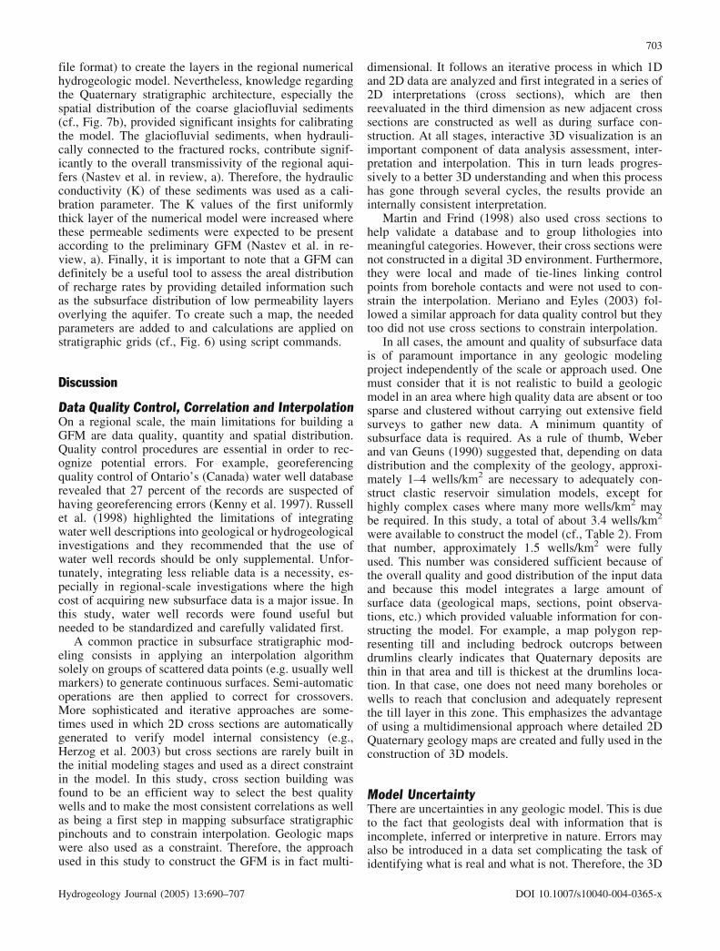
file format) to create the layers in the regional numericalhydrogeologic model. Nevertheless, knowledge regardingthe Quaternary stratigraphic architecture, especially thespatial distribution of the coarse glaciofluvial sediments(cf., Fig. 7b), provided significant insights for calibratingthe model. The glaciofluvial sediments, when hydrauli-cally connected to the fractured rocks, contribute signif-icantly to the overall transmissivity of the regional aqui-fers (Nastev et al. in review, a). Therefore, the hydraulicconductivity (K) of these sediments was used as a cali-bration parameter. The K values of the first uniformlythick layer of the numerical model were increased wherethese permeable sediments were expected to be presentaccording to the preliminary GFM (Nastev et al. in re-view, a). Finally, it is important to note that a GFM candefinitely be a useful tool to assess the areal distributionof recharge rates by providing detailed information suchas the subsurface distribution of low permeability layersoverlying the aquifer. To create such a map, the neededparameters are added to and calculations are applied onstratigraphic grids (cf., Fig. 6) using script commands.
Discussion
Data Quality Control, Correlation and InterpolationOn a regional scale, the main limitations for building aGFM are data quality, quantity and spatial distribution.Quality control procedures are essential in order to rec-ognize potential errors. For example, georeferencingquality control of Ontario’s (Canada) water well databaserevealed that 27 percent of the records are suspected ofhaving georeferencing errors (Kenny et al. 1997). Russellet al. (1998) highlighted the limitations of integratingwater well descriptions into geological or hydrogeologicalinvestigations and they recommended that the use ofwater well records should be only supplemental. Unfor-tunately, integrating less reliable data is a necessity, es-pecially in regional-scale investigations where the highcost of acquiring new subsurface data is a major issue. Inthis study, water well records were found useful butneeded to be standardized and carefully validated first.
A common practice in subsurface stratigraphic mod-eling consists in applying an interpolation algorithmsolely on groups of scattered data points (e.g. usually wellmarkers) to generate continuous surfaces. Semi-automaticoperations are then applied to correct for crossovers.More sophisticated and iterative approaches are some-times used in which 2D cross sections are automaticallygenerated to verify model internal consistency (e.g.,Herzog et al. 2003) but cross sections are rarely built inthe initial modeling stages and used as a direct constraintin the model. In this study, cross section building wasfound to be an efficient way to select the best qualitywells and to make the most consistent correlations as wellas being a first step in mapping subsurface stratigraphicpinchouts and to constrain interpolation. Geologic mapswere also used as a constraint. Therefore, the approachused in this study to construct the GFM is in fact multi-
dimensional. It follows an iterative process in which 1Dand 2D data are analyzed and first integrated in a series of2D interpretations (cross sections), which are thenreevaluated in the third dimension as new adjacent crosssections are constructed as well as during surface con-struction. At all stages, interactive 3D visualization is animportant component of data analysis assessment, inter-pretation and interpolation. This in turn leads progres-sively to a better 3D understanding and when this processhas gone through several cycles, the results provide aninternally consistent interpretation.
Martin and Frind (1998) also used cross sections tohelp validate a database and to group lithologies intomeaningful categories. However, their cross sections werenot constructed in a digital 3D environment. Furthermore,they were local and made of tie-lines linking controlpoints from borehole contacts and were not used to con-strain the interpolation. Meriano and Eyles (2003) fol-lowed a similar approach for data quality control but theytoo did not use cross sections to constrain interpolation.
In all cases, the amount and quality of subsurface datais of paramount importance in any geologic modelingproject independently of the scale or approach used. Onemust consider that it is not realistic to build a geologicmodel in an area where high quality data are absent or toosparse and clustered without carrying out extensive fieldsurveys to gather new data. A minimum quantity ofsubsurface data is required. As a rule of thumb, Weberand van Geuns (1990) suggested that, depending on datadistribution and the complexity of the geology, approxi-mately 1–4 wells/km2 are necessary to adequately con-struct clastic reservoir simulation models, except forhighly complex cases where many more wells/km2 maybe required. In this study, a total of about 3.4 wells/km2
were available to construct the model (cf., Table 2). Fromthat number, approximately 1.5 wells/km2 were fullyused. This number was considered sufficient because ofthe overall quality and good distribution of the input dataand because this model integrates a large amount ofsurface data (geological maps, sections, point observa-tions, etc.) which provided valuable information for con-structing the model. For example, a map polygon rep-resenting till and including bedrock outcrops betweendrumlins clearly indicates that Quaternary deposits arethin in that area and till is thickest at the drumlins loca-tion. In that case, one does not need many boreholes orwells to reach that conclusion and adequately representthe till layer in this zone. This emphasizes the advantageof using a multidimensional approach where detailed 2DQuaternary geology maps are created and fully used in theconstruction of 3D models.
Model UncertaintyThere are uncertainties in any geologic model. This is dueto the fact that geologists deal with information that isincomplete, inferred or interpretive in nature. Errors mayalso be introduced in a data set complicating the task ofidentifying what is real and what is not. Therefore, the 3D
703
Hydrogeology Journal (2005) 13:690–707 DOI 10.1007/s10040-004-0365-x

model presented in Fig. 7 is probably the most consistentscenario according to available data and actual knowledgeof the system but it is assumed that the stratigraphic ar-chitecture is incomplete and contain uncertainties. Ingeneral, uncertainty increases with geological complexity,total sediment thickness, distance from reliable boreholesand, to a degree, cross sections.
Linkages With Process-based ModelsComputational grids for numerical models must be op-timized to produce accurate and stable numerical solu-tions such that some geometric generalizations may bedone in practice (Anderson and Woessner 1992). As aresult, multi-layered hydrostratigraphic models are usu-ally designed to fit the specific requirements of both thenumerical modeling strategy and a particular softwarepackage (e.g., MODFLOW, FEFLOW, FRAC3DVS,etc.). The main advantage is that the hydrostratigraphicmodel is readily available for numerical modeling.
However, this approach has a number of disadvan-tages, especially in regional projects with multiple ob-jectives and planned end-products. The model may notcontain sufficient stratigraphic details to meet the re-quirements of a subsequent numerical modeling phase orfor another application within the same project; consid-erable effort may then be required to add the right degreeof complexity to the stratigraphic reconstruction. In thisstudy, an approach in which the stratigraphic model isdesigned to better allow for multiple usages was chosenin order to accommodate many applications. With suchan approach, a model tends to have, as much as the dataallow, the stratigraphic details required by the most de-manding application of the project. The needed simpli-fications/approximations are more likely to be consistentwhen they are carried out after such a 3D geomodelingeffort. However, there is a price to pay to obtain thisflexibility, i.e. a model allowing multiple usages: TheGFM needs to be modified and transferred to the end-process technology. It must therefore be easily exportableand it must be adaptable to fit the specific requirementsof the end-process technology. This problem has beenaddressed by other researchers and different solutions fortransferring data or for generating grids, for instanceMODFLOW-compatible grids, from geologic modelshave been proposed (Jones et al. 2002; Herzog et al.2003).
The software gOcad offers some interesting toolswhich provide the means to pre-process a GFM and toexport data in different ways in order to be used either byfinite difference or finite element codes. However, theresulting grids are not necessarily fully compatible withthe code used for flow modeling. Therefore, it may still bepreferable to export the needed information and generatethe grid in the same system that carries out the simulation.Part or all of the needed stratigraphic information con-tained in the GFM can be exported as ASCII or DXF filesin the end-process technology. Most numerical modelingpackages can handle such files. The discontinuous layers
can be transformed into continuous units with a minimumthickness in their extended parts. This can act as back-bones from which further discretization and grid refine-ment can be applied using appropriate grid generationtools and on which initial and boundary conditions areassigned for groundwater flow simulation. Nevertheless,data transfers could be much improved by developingappropriate interfaces between geomodeling packagesand groundwater flow modeling systems. For instance,grid generation and data exchange tools in gOcad arecompatible with some end-process technologies used inthe oil industry (VIP and Eclipse). The same thing couldbe done to improve linkages with currently-used ground-water flow modeling packages.
Time ConstraintsThe time frame of a project is an important factor in theconsideration of the modeling approach. The procedureoutlined in this paper takes into account the potentiallimitations induced by this time frame and follows a step-by-step approach (cf., Fig. 6) during which the com-plexity and the consistency of the model increase towardsthe desired level. This is particularly useful since acomplete GFM is expected to be available quite late inthe investigation process while preliminary products areneeded before the end of the study. In this study, about 8months were required for one person to develop theprocedure, transfer the data, construct the cross sectionsand the ensuing GFM, which also includes softwaretraining. For a 3-year project, which is a reasonable du-ration for a regional study, this would represents 22 per-cent of the project’s time frame. Everything else beingequal (scale, human resources, training, etc.), this is notmuch more than what is required to complete a 2DQuaternary geological map or to construct a 2.5D multi-layered subsurface model using standard GIS tools. Infact, independently of the approach used, more time isusually spent gathering data, developing the database andverifying its quality. The benefits of using a 3D approachoutweigh the limitations but the additional time requiredby this approach could be less constraining by starting thegeologic survey before the onset of the hydrogeologicsurvey. The most complete and consistent GFM wouldthus be more readily available for process-based simula-tions and other uses.
Future DevelopmentsSome improvement to the workflow can be developed inorder to accelerate model construction and to reduce theprobability of unnoticed errors. In the present work, it wasconsidered feasible to flag automatically anomalousboreholes and to verify them manually. However, the useof an expert system would probably accelerate the processespecially with large databases. In future projects, dataquality control and cross section building will most likelybe all carried out using a single geomodeling tool whichwill reduce software interplay. Further integration of data
704
Hydrogeology Journal (2005) 13:690–707 DOI 10.1007/s10040-004-0365-x

and knowledge could be obtained by including the mainarchitectural features of bedrock geology. There is also aneed to implement other grid generation tools currentlyused in hydrogeology into geomodeling systems and toprovide other appropriate interfaces to improve inter-op-erability between software and to enable more efficientinteractions between different specialists using the model.The most interesting one being an interface between theGFM and the hydrogeologic numerical model. More ef-fective linkages are also needed with database systems.
Conclusion
A computer-based 3D Geologic Framework Model(GFM) was built during a regional hydrogeologic surveyin southwestern Quebec, Canada. The purpose of con-structing such a model is to obtain a consistent repre-sentation of the stratigraphic architecture, as it is under-stood from the available data, and to use it for qualitativeand quantitative geologic/hydrogeologic analyses. It is theview of the authors that a three-dimensional modelingapproach is the most adequate way to capture the sub-surface complexity of most geologic settings, which canlead, in the context of an integrated approach, to im-proved hydrogeologic appraisals. This paper has shownsome of the significant advantages of using such a 3Dgeomodeling approach for hydrogeologic applications.With increasing availability/accessibility to technology,3D geomodeling is expected to become a standard in thenear future. However, reconstructing the stratigraphicarchitecture in 3D is not a trivial task and close interac-tions with some hydrogeologic applications such asgroundwater flow modeling remains a significant chal-lenge. The results of the geomodeling effort presented inthis paper have thus highlighted a series of advantagesand limitations regarding the proposed approach, whichcan be summarized as follows:
Limitations1) Many manual corrections are still required to get fully
satisfying results in complex settings;2) Model reliability is limited by data quantity and
quality and, since it is a knowledge-based model, bythe experience of experts and the efficiency of theirinteraction;
3) More reliable regional geologic models could be pro-duced if training, regulations and a standardized pro-cedure were developed to improve the quality of waterwell databases;
4) Improvement in the inter-operability with databasesystems and end-process technologies need to beachieved in order to further increase the usefulness ofthese models and to streamline the process of dataexchange;
5) Such a procedure is perhaps not yet within the reach ofevery organization but this is likely to improve in thenear future.
Advantages1) The geologic model is made of interlocked discrete
surfaces which represent current knowledge of thestratigraphic architecture of the modeled domain in acommon and consistent framework which does notrequire large computer power;
2) It truly helps to understand the geologic and hydro-geologic settings and can provide complex and con-sistent end-products as well as simplified frameworkdepending on the needs of the application (hydrogeo-logic settings characterization, aquifer vulnerabilitymapping, groundwater flow simulation, etc.);
3) It is thus a step toward more integrated approacheswhere data and knowledge are grouped in a commonsystem/model to reduce redundancy. It allows formultiple usages and improves the consistency/unifor-mity between end-products. It also contributes tostreamline updating procedures;
4) The method is efficient enough for one person togather the data, verify the quality and construct themodel in a time frame which should be less than 20–25% of the total amount of time (typically 3 years)devoted to a regional hydrogeology project.
Acknowledgments This paper is part of a Ph.D. dissertation atINRS Eau, Terre et Environnement. The work was supported byNatural Resources Canada, Economic Development Canada, Con-seil R�gional de D�veloppement-Laurentides, Minist�re de l’En-vironnement du Qu�bec, and the Regional County Municipalities ofArgenteuil, Deux-Montagnes, Mirabel and Th�r�se-de-Blainville.Financial support to the first author was provided through schol-arships from the Fonds Qu�b�cois de la Recherche sur la Nature etles Technologies and computing resources were provided by theLaboratory of numerical cartography and photogrammetry of theGeological Survey of Canada (Quebec office). The authors wouldlike to thank Dr. Martine M. Savard, Dr. Daniel Lebel, Dr. RichardMartel, Dr. Miroslav Nastev and ric Boisvert for helpful discus-sions and Kathleen Lauzi�re for valuable advice in database man-agement. Genevi�ve Delage, Jos�e Thibodeau and Luc Mass�provided technical help. Dr. Alfonso Rivera and two reviewers, Dr.Koen Verbruggen and an anonymous reviewer, critically read themanuscript and contributed much to its improvement. This paper isGeological Survey of Canada contribution #2003079.
References
Alms R, Klesper C, Siehl A (1996) Three-dimensional modeling ofgeological features with examples from the Cenozoic lowerRhine Basin. In: Forster A, Merriam DF (eds) GeologicalModeling and Mapping, Plenum Press, New York: 113–133;merica Bulletin, v. 101:501–51
Anderson MP, Woessner WW (1992) Applied groundwater mod-eling; simulation of flow and advective transport. AcademicPress, New York
Artimo A, M�kinen J, Berg RC, Abert CC, Salonen V-P (2003)Three-dimensional geologic modeling and visualization of theVirttaankangas aquifer, southwestern Finland. HydrogeologyJournal, 11:378–386
Belcher WR, Faunt CC, D’Agnese FA (2002) Three-dimensionalhydrogeologic framework model for use with a steady-statenumerical ground-water flow model of the Death Valley re-gional flow system, Nevada and California. US GeologicalSurvey, Water-Resources Investigations Report 01–4254
Benjumea B, Hunter JA, Good RL, Burns RA, Ross M (2001)Application of high resolution seismic reflection techniques in
705
Hydrogeology Journal (2005) 13:690–707 DOI 10.1007/s10040-004-0365-x

Champlain sea sediments near Lachute — St. Benoit, Quebec.In: Current Research, 2001-D5, Geological Survey of Canada
Berg RC, Bleuer BE, Jones KA, Kincare RR, Stone BD (2000)Mapping the glacial geology of the Central Great Lakes regionin three dimensions — a model for state-federal cooperation.USGS, open-file report 99–349
Boisvert , Michaud Y (1998) Gestion des donn�es de forage l’aide d’une approche topologique: application au projet decartographie hydrog�ologique du pi�mont laurentien, Qu�bec.(Managing borehole data using a topologic approach) In:Current Research 1998-E, Geological Survey of Canada, pp117–124 (in French)
Bolduc AM, Ross M (2000) La g�ologie et la g�omorphologiequaternaire des basses Laurentides (ouest de Montr�al). (Qua-ternary geology and geomorphology of the basses Laurentides(west of Montreal). Field Guide, AQQUA-CGRG (in French)
Bolduc AM, Ross M (2001a) Surficial Geology, Lachute-Oka,Qu�bec. Geological Survey of Canada, Open File 3520,1:50,000
Bolduc, A.M., Ross M (2001b) Surficial Geology, Laval, Qu�bec.Geological Survey of Canada, Open File 3878, 1:50,000
Bonham-Carter GF (2000) Geographic Information Systems forgeoscientists: Modelling with GIS. Pergamon Press, Oxford
Breunig M (1999) An approach to the integration of spatial data andsystems for a 3D geo-information system. Computers & Geo-sciences 25:39–48
BRGM, ENSMP, INRIA (1997) Colloque Mod�lisation du sous-sol, 3–4 f�vrier 1997. Subsurface modeling workshop, BRGM,274, coll. Techniques et M�thodes (Techniques and methods)(in French)
Clayton R (2000) Geologic framework model (GFM3.1). MDL-NBS-GS-000002 REV00 ICN 01, Las Vegas, CRWMS M&O
Cloutier V, Bourque E, Lefebvre R, Savard MM, Nastev M, MartelR, Therrien R (2001) Regional hydrogeochemical characteri-zation of groundwater in fractured rock aquifers. In: 2nd jointIAH-CGS groundwater conf, 2001 an Earth Odyssey, Proc 2,pp 1,068–1,077
Courrioux, G, Nullans S, Guillen A, Boissonnat JD, Repusseau P,Renaud X, Thibaut M (2001) 3D volumetric modelling ofCadomian terranes (Northern Brittany, France): an automaticmethod using Vorono� diagrams. Tectonophysics 331:181–196
Earth Decision Sciences (2001) GOCAD 2.0 user’s manual.1,564 pp
Eyles N, Eyles CH, Miall AD (1983) Lithofacies types and verticalprofile models, an alternative approach to the description andenvironmental interpretation of glacial diamict and diamictitesequences. Sedimentology 30:393–410
Fleming AH (1998a) Using glacial terrain models to define hy-drogeologic settings in heterogeneous depositional systems. In:Fraser GS, Matthew DJ (eds) Hydrogeologic models of sedi-mentary aquifers, SEPM (Society for Sedimentary Geology):25–46
Fleming AH (1998b) Using glacial terrain models to characterizeaquifer system structure, heterogeneity and boudaries in aninterlobate basin, northeastern Indiana. In: Fraser GS, MatthewDJ (eds) Hydrogeologic models of sedimentary aquifers, SEPM(Society for Sedimentary Geology): 47–68
Fraser GS, Bleuer NK (1987) Use of facies models as predictivetools to locate and characterize aquifers in glacial terrains. In:Proceedings, NWWA Conf on Midwestern Groundwater Is-sues: National Water Well Association, pp 123–143
Frind EO, Muhammad DS, Molson JW (2002) Delineation of three-dimensional well capture zones for complex multi-aquifersystems. Ground Water 40(6):586–598
Gerber RE, Howard KWF (1996) Evidence for recent groundwaterflow through Late Wisconsinan till near Toronto, Ontario. CanGeotech J 33:538–555
Girard F (2001) Architecture et hydrostratigraphie d’un complexemorainique et delta�que dans la r�gion de Saint-Raymond dePortneuf, Qu�bec. (Architecture and hydrostratigraphy of amorainic and deltaic system in the Saint-Raymond de Portneuf
region, Qu�bec), unpublished master thesis, Universit� duQu�bec, INRS-G�oressources [in French]
Globensky Y (1987) G�ologie des Basses-Terres du Saint-Laurent.(Geology of the St. Lawrence Lowlands), Quebec Ministry ofnatural resources, MM 85–02 (in French)
Geologic Sensitivity Workgroup (GSW) (1991) Criteria andguidelines for assessing geologic sensitivity of groundwaterresources in Minnesota. Dept. of Natural Resources, Div. ofWaters, Minnesota
Hamel A, Therrien R, G�linas PJ (2001) Groundwater rechargeof fractured rock aquifers in southwestern Qu�bec. 2nd jointIAH-CGS groundwater conf, 2001 an Earth Odyssey, Proc 2,pp 1078–1084
Hamilton DE, Jones TA, (�ds) (1992) Computer modeling of ge-ologic surfaces and volumes. AAPG Computer Applications inGeology, no. 1
Herzog BL, Larson DR, Abert CC, Wilson SD, Roadcap GS (2003)Hydrostratigraphic modeling of a complex, glacial-drift aquifersystem for importation into MODFLOW. Groundwater, 41(1):57–65
Hillaire-Marcel C. (1974) La d�glaciation au nord-ouest de Mon-tr�al: donn�es radiochronologiques et faits stratigraphiques.The deglaciation northwest of Montreal: radiochronologic dataand stratigraphic facts), Revue de g�ographie de Montr�al(Montreal geography journal), 28(4):407–417 (in French)
Houlding SW (1994) 3D Geoscience Modeling: Computer tech-niques for geological characterization. Springer, Berlin Heidel-berg New York
Jessel M (2001) Three-dimensional geological modelling of po-tential-field data. Computers & Geosciences 27:455–465
Jones NL, Budge TJ, Lemon AM, Zundel AK (2002) GeneratingMODFLOW grids from boundary representation solid models.Groundwater 40(2):194–200
Kenny FM, Hunter G, Chan P (1997) Georeferencing qualitycontrol of Ontario’s water well data base for the GreaterToronto and Oak Ridges Moraine areas of Southern Ontario. In:Proceedings of the 1997 Canadian Geomatics conf, GER ‘97,abstract 219
Kugler-Gagnon, M (1974) Information g�oscientifique et am�-nagement. (Geoscientific information and land management)unpublished Ph.D thesis, Ottawa University (in French)
L�vesque G (1982) G�ologie des d�p�ts quaternaires de la r�gionde Oka-Ste-Scholastique, Qu�bec. (Geology of Quaternarydeposits of the Oka-Ste. Scholastique region, Quebec), un-published master thesis, Universit� du Qu�bec Montr�al (inFrench)
Lloyd JW (1983) Hydrogeological investigations in glaciated ter-rains. In: Eyles N (ed) Glacial geology; An introduction forengineers and earth scientists. Oxford, Pergamon Press: 349–368
Logan C, Russell HAJ, Sharpe DR (2001) Regional three-dimen-sional stratigraphic modelling of the Oak Ridges Moraine area,southern Ontario. In: Current Research 2001-D1, GeologicalSurvey of Canada
Mallet J-L (1989) Discrete smooth interpolation. Association forComputing Machinery: ACM-Transactions on Graphics, 8(2):121–144
Mallet J-L (1992) gOcad: A computer-aided design program forgeological applications. In: Turner K (ed) Three-dimensionalmodeling with Geoscientific Information Systems, KluwerAcademic Publishers, Dordrecht, Holland, Nato ASI Series C,354:123–141
Mallet J-L (2002) Geomodeling. In: Journel AG (ed) Appliedgeostatistics series, Oxford University Press, Oxford
Mallet J-L (2003) Geomodeling: Shared-Earth-Model and SGrids.2003 gOcad consortium report. Nancy School of Geology,Nancy, France
Marschallinger (1991) Interface programs to enable full 3-D geo-logical modeling with a combination of Autocad and Surfer.Computers & Geosciences 17(10):1,383–1,394
Martin PJ, Frind EO (1998) Modeling a complex multi-aquifersystem: the Waterloo Moraine. Groundwater 36(4):679–690
706
Hydrogeology Journal (2005) 13:690–707 DOI 10.1007/s10040-004-0365-x

Maxe L, Johansson P-O (1998) Assessing groundwater vulnera-bility using travel time and specific area as indicators. Hydro-geology Journal 6(3):441–449
Meriano M, Eyles N (2003) Groundwater flow through Pleistoceneglacial deposits in the rapidly urbanizing Rouge River-High-land Creek watershed, City of Scarborough, southern Ontario,Canada. Hydrogeology Journal 11(2):288–303
Miall AD (1992) Principles of sedimentary basin analysis, 2nd ed,Springer, Berlin Heidelberg New York
Nastev M, Savard MM, Lapcevic P, Paradis D, Lefebvre R, MartelR (2001) Investigation of hydraulic properties of regionalfractured rock aquifers. 2nd joint IAH-CGS groundwater conf,2001 an Earth Odyssey, Proc 2, pp 1,058–1,067
Nastev M, Rivera A, and Lefebvre R (in review, a) Numericalsimulation of regional flow in sedimentary rock aquifers.Hydrogeology Journal
Nastev M, Savard MM, Lapcevic P, Lefebvre R, Martel R (inreview, b) Hydraulic properties and scale effects investigationin regional rock aquifers. Hydrogeology Journal
Parent M, Michaud Y, Boisvert et al. (1998) Cartographie hy-drog�ologique r�gionale du pi�mont laurentien dans la MRCde Portneuf: g�ologie et stratigraphie des formations super-ficielles. (Regional hydrogeologic mapping of the laurentianpiedmont in the Portneuf county municipality: geology andstratigraphy of the surficial formations.) Geological Survey ofCanada, Open File 3664-a. (in French)
Parent M, Girard F, Fagnan N, Michaud Y, Boisvert E, Fortier R(2003) Caract�risation g�ologique des formations superficiellesenfouies. (Geological characterization of buried surficial for-mations) In: Y Michaud, R Lefebvre and R McCormack (eds)Guide m�thodologique pour la cartographie hydrog�ologiquer�gionale des aquif�res granulaires de surface. (Methodologicalguidebook for the regional hydrogeologic cartography of shal-low granular aquifers), Unpublished report: 30–53 (in French)
Pflug R, Harbaugh JW (eds) (1992) Computer graphics in geology:Three-dimensional computer graphics in modeling geologicstructures and simulating geologic processes. Springer-Verlag,London
Prichonnet G (1977) La d�glaciation de la Vall�e du Saint-Laurentet l’invasion marine contemporaine. (The deglaciation of the St.Lawrence Valley and the contemporaneous marine invasion),G�ographie physique et Quaternaire, (Quaternary and physicalgeography), 31:323–345 (in French)
Ragan D (1985) Structural geology—an introduction to geometricaltechniques. (third edition), John Wiley and Sons, New York
Raper J (ed) (1989) Three dimensional applications in geographicalinformation systems. Taylor and Francis, London
Ricketts BD (ed) (2000) Mapping, geophysics, and groundwatermodelling in aquifer delineation, Fraser Lowland and Delta,British Columbia. Geological Survey of Canada, Bulletin 552
Ross M, Parent M, Bolduc AM, Hunter J, Benjumea B (2001) tude pr�liminaire des formations quaternaires comblant lesvall�es des basses Laurentides, nord-ouest de Montr�al, Qu�-bec. (Preliminary study of the Quaternary valley fills of thebasses Laurentides, northwest of Montreal, Quebec), In: Cur-rent Research 2001-D5, Geological Survey of Canada (inFrench)
Ross M, Parent M, Lefebvre R, Martel R (2002) 3D geologicframework for regional hydrogeology and land-use manage-ment; a case study from Southwestern Quebec, Canada. In:
R.C. Berg and L.H. Thorleifson (convenors), Three-dimen-sional geological mapping for groundwater applications, work-shop extended abstracts, Geological Survey of Canada, OpenFile 1449, pp 52–55
Ross M, Martel R, Parent M, Lefebvre R, Savard MM (2003) Theuse of a 3D geologic framework model of surficial sediments todefine bedrock aquifer vulnerability in the St. Lawrence Low-lands, Quebec, Canada. In: Rodriguez R, Civita M, de Maio M(eds), proceedings of the First International Workshop onAquifer Vulnerability and Risk, Salamanca, Mexico, vol. 1,pp 157–168
Ross M, Martel R, Parent M, Lefebvre R, Savard MM (in press)The use of a 3D geologic framework model of surficial sedi-ments to define bedrock aquifer vulnerability in the St. Law-rence Lowlands, Quebec, Canada, Geofisica Internacional
Russell HAJ, Brennand TA, Logan C, Sharpe DR (1998) Stan-dardization and assessment of geological descriptions fromwater well records, Greater Toronto and Oak Ridge Moraineareas, southern Ontario. In: Current Research 1998-E, Geo-logical Survey of Canada, pp 89–102
Savard MM, Nastev M, Lefebvre R, Martel R et al. (2000) Regionalhydrogeology of fractured rock aquifers in Southwestern Que-bec (St.Lawrence Lowlands). In: 53rd Canadian GeotechnicalConf, 1st Joint IAH-CNC and GSC Groundwater SpecialtyConf Proc, pp 247–253
Schetselaar EM, (1995) Computerized field-data capture and GISanalysis for generation of cross sections in 3-D perspectiveviews. Computers and Geosciences, v. 21(5):687–701
Sharpe DR, Dyke LD, Hinton MJ, Pullan SE, Russell HAJ,Brennand TA, Barnett PJ, Pugin A (1996) Groundwater pro-spects in the Oak Ridges Moraine area, southern Ontario: ap-plication of regional geological models. In: Current Research1996-E, Geological Survey of Canada: 181–190
Soller DR, Price SD, Kempton JP, Berg RC (1999) Three-dimen-sional geologic maps of Quaternary sediments in east-centralIllinois. U.S. Geological Survey, Geologic InvestigationsSeries, Map I-2669, 3 sheets, 1:500,000
St-Onge DA (1979) Forages au roc, r�gion Nord de Montr�al.(Boreholes reaching bedrock north of Montreal) Ottawa Uni-versity, research notes no.22 (in French)
Thorleifson LH, Matile GLD, Pyne DM, Keller GR (2001) Con-struction of a geological model of the Winnipeg region forgroundwater modeling. In: Thorleifson LH, Berg RC (eds)Geological models for groundwater flow modeling. WorkshopExtended abstracts, 35th annual meeting, North-Central Sec-tion, Geological Society of America, Illinois, Open file series2001-1, pp 52–54
Turner KA (ed) (1992) Three-dimensional modeling with geosci-entific information systems. NATO ASI Series C: Mathemati-cal and Physical Sciences, v. 354
US Department of Energy (1997) Regional groundwater flow andtritium transport modeling and risk assessment of the Under-ground Test Area, Nevada Test Site, Nevada. US Departmentof Energy Report DOE/NV-477 (Underground Test Area sub-project, Phase I data analysis task, vol. 1, Regional geologicmodel data documentation package, ITLV/10972–81)
Weber KJ, van Geuns LC (1990) Framework for constructingclastic reservoir simulation models. Journal Petroleum Tech-nology, 42:1,248–1,253, 1,296–1,297
707
Hydrogeology Journal (2005) 13:690–707 DOI 10.1007/s10040-004-0365-x