3d graphics hardware - cs.cmu.edu · 3d graphics hardware 15-463 graphics ii spring 1999. topics...
TRANSCRIPT
3D Graphics Hardware
15-463 Graphics II
Spring 1999
Topics
Graphics Architecture
Uniprocessor Acceleration
Front-End Multiprocessing– Pipelined
– Parallel
Back-End Multiprocessing– Pipelined
– Parallel
Graphics Architecture
Programming Interface
Database contains primitives from model
Immediate mode– Program calls library with individual primitives
– Need to enmumerate entire database for each frame
– No temporal coherence between frames
Retained mode– Primitives are remembered between frames
– Program calls library to make incremental changes
– Can potentially exploit temporal coherence
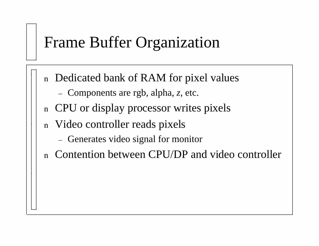
Frame Buffer Organization
Dedicated bank of RAM for pixel values– Components are rgb, alpha, z, etc.
CPU or display processor writes pixels
Video controller reads pixels– Generates video signal for monitor
Contention between CPU/DP and video controller
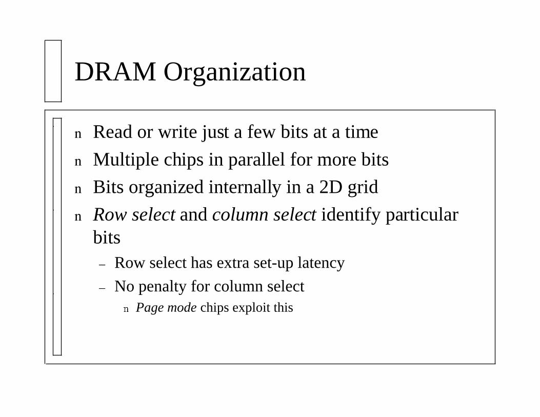
DRAM Organization
Read or write just a few bits at a time
Multiple chips in parallel for more bits
Bits organized internally in a 2D grid
Row select and column select identify particularbits– Row select has extra set-up latency
– No penalty for column selectPage mode chips exploit this
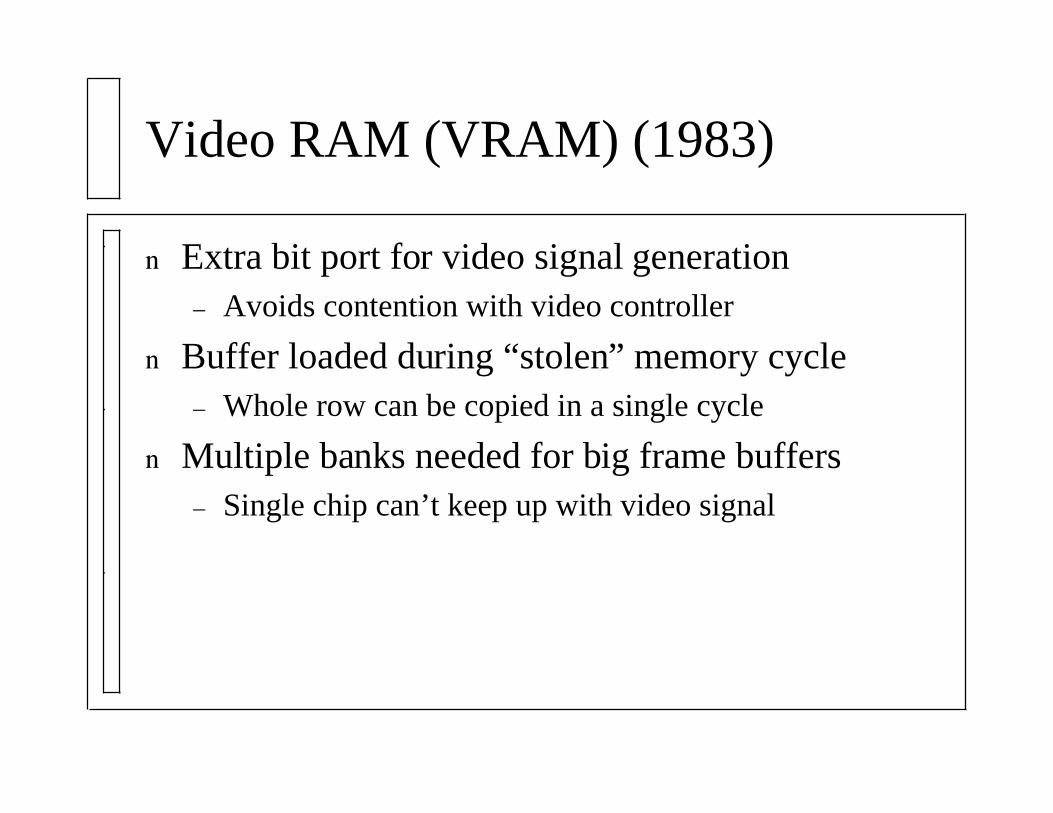
Video RAM (VRAM) (1983)
Extra bit port for video signal generation– Avoids contention with video controller
Buffer loaded during “stolen” memory cycle– Whole row can be copied in a single cycle
Multiple banks needed for big frame buffers– Single chip can’t keep up with video signal
Uniprocessor Acceleration
Peripheral Display Processor
Reads/writes frame buffer in place of CPU
Acceleration for 2D operations
Read/write many pixels in parallel
Built-in support for lines, circles, bitblt, etc.
No transformations, floating-point, etc.
Now limited only by speed of memory
CPU Extensions
Additional instructions in CPU for 3D graphics
Pioneered by i860 (1989)– 64-bit pixel operations: linear interpolation, z-buffer
compare, conditional update
MMX (1995?)– Reinterprets x86 floating-point “registers”
– Up to 8 simultaneous integer operations8x8bit, 4x16bit, 2x32bit, 1x64bit
(Clamped) arithmetic, logical, pack/unpack
3DNow (1998)
Reinterprets MMX registers
Two simultaneous floating-point operations– Add, subtract, multiply, min, max, etc.
– Reciprocal and reciprocal square root approximationThree instructions implement Newton’s method
On-chip table lookup for initial approximation
Two successive iterations to refine approximation
Superscalar execution permits 4 operations/cycle
Performance Barriers
Floating-point geometry processing– Transformation, clipping, lighting
Integer pixel processing– Scan conversion
Frame-buffer memory bandwidth– Z-buffer comparison, shading, alpha blending
What can we do about these?

Front-End Multiprocessing
Pipelining
Extra processors for distinct tasks
Primitives are processed in discrete stages– Need result of stage i to compute stage i+1
Process stage i of primitive j concurrently withstage i+1 of primitive j+1
Increase in throughput, (small) increase in latency– Individual latency usually isn’t important
Parallelism
Extra processors for uniform tasks
SIMD– One instruction affects multiple operands
– “Disable bit” for conditional operations
– Advantage: no extra control logic
– Disadvantage: inflexible for non-uniform tasks
– Examples: MMX, 3DNow
MIMD– Each processor has its own instruction stream
– Synchronization/interconnect can be difficult
Pipeline Front End
Many distinct stages naturally lead to pipelining
CPU usually handles display traversal
Geometry subsystem is floating-point intensive– Transformations can be done in parallel
By component
By vector (vertex or normal)
– Transformation bundled with trivial accept/reject
– One processor per clip plane
– Division by w is expensiveCompute 1/w and multiply x, y, and z by that
Geometry Engine (1982)
Used in early SGI machines
~One chip per stage of front-end pipeline– Configuration word determines which stage
Each chip reads and writes command stream– Vertices inserted and deleted during clipping
Replaced by commodity chips in later SGIs– Weitek 3332 and Intel i860
Parallel Front End
Significantly harder than pipelining front end– Need to recombine streams at back end for ordered
rendering algorithms
– Processor contention over shared database
RealityEngine processes geometry in parallel– Command processor sends primitives to geometry
engines in round robin order
– Geometry engine is not pipelined (single i860)
– Triangle bus broadcasts transformed triangles to back-end processors
Back-End Multiprocessing
Taxonomy
Object order: outer loop over objects– Z-buffer, depth-sort, and BSP-tree algorithms
Image order: outer loop over pixels
Image parallel = parallel object order– Parallel inner loop over image pixels
– Partitioned image, logic-enhanced memory
Object parallel = parallel image order– Parallel inner loop over objects
– Processor-per-primitive, tree-structured
Pipelined Object Order
Polygon-edge-span processor pipeline– Polygon unit finds x, z, and rgb deltas for each edge
– Edge unit computes left/right x, z, and rgbbounds/deltas for each span
– Span unit interpolates z and rgb for each pixelImplements z buffer compare
Poor load balance: span processor is bottleneck– Polygons*edges*spans*pixels
– Pixel cache to increase memory bandwidthExcellent locality
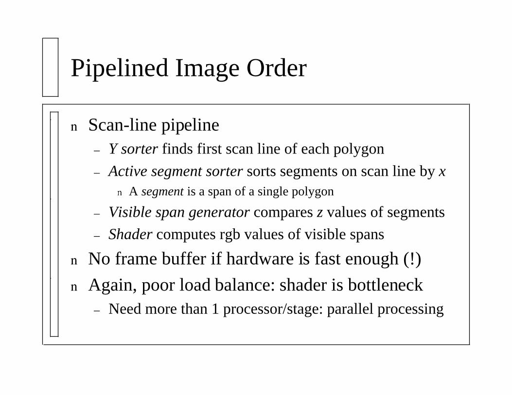
Pipelined Image Order
Scan-line pipeline– Y sorter finds first scan line of each polygon
– Active segment sorter sorts segments on scan line by xA segment is a span of a single polygon
– Visible span generator compares z values of segments
– Shader computes rgb values of visible spans
No frame buffer if hardware is fast enough (!)
Again, poor load balance: shader is bottleneck– Need more than 1 processor/stage: parallel processing
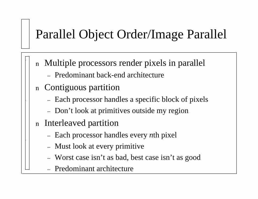
Parallel Object Order/Image Parallel
Multiple processors render pixels in parallel– Predominant back-end architecture
Contiguous partition– Each processor handles a specific block of pixels
– Don’t look at primitives outside my region
Interleaved partition– Each processor handles every nth pixel
– Must look at every primitive
– Worst case isn’t as bad, best case isn’t as good
– Predominant architecture
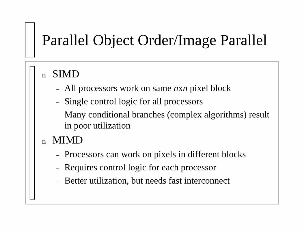
Parallel Object Order/Image Parallel
SIMD– All processors work on same nxn pixel block
– Single control logic for all processors
– Many conditional branches (complex algorithms) resultin poor utilization
MIMD– Processors can work on pixels in different blocks
– Requires control logic for each processor
– Better utilization, but needs fast interconnect
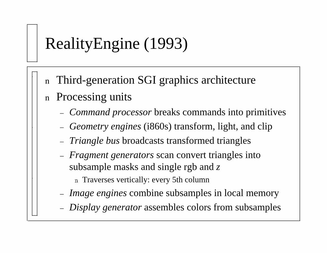
RealityEngine (1993)
Third-generation SGI graphics architecture
Processing units– Command processor breaks commands into primitives
– Geometry engines (i860s) transform, light, and clip
– Triangle bus broadcasts transformed triangles
– Fragment generators scan convert triangles intosubsample masks and single rgb and z
Traverses vertically: every 5th column
– Image engines combine subsamples in local memory
– Display generator assembles colors from subsamples
Logic Enhanced Memory
Massively parallel approach
Processing elements built into memory chips– Overcomes memory bandwidth limitations
Interconnect between chips can be difficult
Custom logic increases cost of chips– Ordinary DRAM has vast economy of scale
Pixel Planes (1981)
1-bit processor associated with each pixel– Enable bit for pixels inside polygon
Linear expression tree evaluates linear equationsin parallel– F(x, y) = Ax + By + C
– Edges of convex polygon
– Depth value of points in a triangle
– Color components for Gouraud shading
Constant rendering time for any size polygon!
Parallel Polygon Rasterization
Used by RealityEngine fragment generators
Edge functions similar to Pixel Planes linearexpressions
nxn block of pixel logic traverses frame buffer
Traversal algorithm affects performance– Vertex bounding box (simplest)
– Edge-to-edge: search for left edge at each scan line
– Center line: search left and right from interior
Can clip just by adding edges
Parallel Image Order/Object Parallel
Specific primitives assigned to each processor– Usually 1 primitive per processor
Fragments combined from each processor output
Processor-per-primitive pipeline– My z > previous z: pass my rgb and z to next
– My z < previous z: pass rgb and z unchanged
Processor-per-primitive tree– Merge rgb and z streams using binary tree
Performance drops if #primitives > #processors
Talisman (1996)
Microsoft design for PC 3D hardware
Retained mode API
Distinct image layers for independent objects
Image layers are composited during video signalgeneration
Layer transformations for simple effects
Layers are compressed by hardware
References
Foley and van Dam, Chapter 18
Kurt Akeley, “RealityEngine Graphics”, SIGGRAPH ‘93
Kurt Akeley, “High-Performance Polygon Rendering”, SIGGRAPH‘88
James H. Clark, “The Geometry Engine: A VLSI Geometry System forGraphics”, SIGGRAPH ‘82
Juan Pineda, “A Parallel Algorithm for Polygon Rasterization”,SIGGRAPH ‘88
Jay Torborg and James T. Kajiya, “Talisman: Commodity Realtime3D Graphics for the PC”, SIGGRAPH ‘96