3d laser range scanner with hemispherical field of...
TRANSCRIPT

1
3D Laser Range Scanner with Hemispherical Fieldof View for Robot Navigation
Julian Ryde and Huosheng Hu
Abstract—For mobile robots to be of value in practical situa-tions a 3D perception and mapping capability will almost alwaysprove essential. In this paper a 2D laser scanner is modified toproduce 3D scans with a resolution of one degree updated every3 seconds. This result is achieved by adding a rotating mirrorto the original scanner in an inexpensive and relatively simplemodification that is easily made to a standard mobile robot. Themodified robot is then able to produces 3D scans at a variousfrequencies up to 1Hz and accurate to 0.02m over an 8m range.
Index Terms—3D laser scanner, mobile robots, range sensors
I. INTRODUCTION
It has proved difficult to provide a robot with the meansof obtaining reliable, 3D information about its environment.So far the two main approaches have been based upon vi-sion and/or laser range finding. Both have been dogged byproblems. Vision is often computationally intensive and suffersfrom sensitivity to changes in illumination. Another source ofdifficulty stems from the need to solve the correspondenceproblem and although this can be reduced to some extent byadopting structured light approaches, data spatial density doesnot approach that delivered by laser scanners. So far non-visual localisation and mapping has taken place in 2D. Themain reason for this in the case of laser range finders is thelimitations imposed by the sensors. In the case of vision the 2Dlimitation has been dictated by limitations in processor speedand the resource intensive nature of the algorithms needed forstereoscopic vision.
Recently in an effort to tap the advantages of 3D sensing,researchers have mounted 2D laser scanners on nodding orrotating mechanisms [1][2][3][4]. What all of these implemen-tations have in common is that they necessitate in various waysthe motion of the entire 2D scanner. Whilst such innovationshave tended to deliver good quality data they have done so atthe cost of significant hardware complexity and concomitantmass and power consumption increases. A popular, alternativeapproach has seen two laser scanners mounted with theirscan planes orthogonal to one another [5]. However whilst itmust be accepted that the orthogonal mounting technique canproduce 3D maps it does not give the robot true 3D sensoryperception and this is essential for reliable obstacle avoidanceand local path planning. Significant attention is now beingfocused on 3D laser mapping [6][7][8].
Julian Ryde is with the Autonomous Systems Laboratory, CSIRO ICTCentre, PO Box 883, Kenmore, QLD 4069, Australia. Huosheng Hu is withthe Department of Computing and Electronic Systems, University of Essex,Wivenhoe Park, Colchester CO4 3SQ, U.K. (E-mail: [email protected],[email protected]). This work was supported by the EPSRC.
There are numerous commercial 3D laser range finders inproduction but these are invariably expensive an appreciablefactor when considering applications involving several robots.In addition commercial range finders are usually aimed at theneeds of surveyors and tend to have a narrow field of viewsacrificing scan rate for high point density. The very fact ofthe number and variety of approaches is a clear illustration ofthe rapidly increasing interest in developing full, 3D sensoryperception for mobile robots in particular.
The benefits of full 3D mapping are manifold and so therapid expansion of this field is inexorable. The detection ofnegative and over-hanging obstacles greatly improves avoid-ance behaviour. Once 3D maps of an environment have beenbuilt they can be customised for needs of, and distributedto, different robots. For instance various 2D occupancy gridsmay be created for robots of different sizes or which have2D sensors at different heights. Severely cluttered and chaoticenvironments such as those attending search and rescue opera-tions may be mapped reliably. Maps that have been based uponthe ceilings of rooms [9] will remain accurate for longer andan unobstructed view of the ceiling is often easily accessibleto a robot even in cluttered environments [10]. A differentapproach that takes advantage of full 3D perception [11]uses virtual 2D scans produced by projecting the 3D datavertically into a plane and then taking the furthest point foreach 2D scan angle. Although this technique produces good2D representations in cluttered environments is suffers fromthe usual disadvantages of 3D sensing technologies - vizslower scan acquisition time and a geometric increase in theamount of data needing to be processed. Some approachescombine both vision and a 3D laser range finder to generatefully textured 3D models of the environment [12].
II. 3D SCANNER DESIGN
A. Hardware Design
Instead of nodding or rotating the laser scanner whichintroduces difficulties in hardware implementation and highpower consumption, we adopted the rotating mirror mecha-nism to produce 3D scans with a field of view up to 120◦
by 270◦ (2), as shown in Fig. 1. It is light, has low powerconsumption and is easily deployed on conventional roboticplatforms. Its accuracy of the laser scanner is fundamentallydependent on precise knowledge of the mirror position. Thereare two main methods to achieve this rotational accuracy:(i) The closed feedback control loop method that requires aangular sensor to measure the angular velocity of the motorto maintain a constant mirror angle velocity and in turn

2
Fig. 1. Top and side views of the enhanced 3D laser scanner. The blockingarms affixed to the mirror edge provide the angular position of the mirrorthrough the laser data.
accurate mirror position; (ii) The open loop control methodthat requires reliable and consistent driving mechanism overmirror revolutions. We have chosen the open loop control inthis research for simplicity. It is accomplished to high accuracywith a quartz oscillator driving a high resolution stepper motor.The closed loop scanner is accomplished with a standard DCmotor and a rotation sensor.
The use of a mirror has a number of advantages, namely lesspower consumption and simpler hardware. The disadvantagesare a reduced scan angle to around 120◦, a blind spot whenthe mirror is edge on and a requirement for more complexgeometric calculations (Fig. 2) to correct for the separationbetween the mirror and the scanner. In Fig. 2 the effect ofthe mirror is to bend part of the xy-coordinate plane to a newelevation.
B. Data Processing Software
The SICK LMS 200 laser scanner is configured to scana 180◦ arc at 1◦ intervals. These settings were chosen tominimize the number of scan points in order to increase thecomplete scan frequency. The scan frequency is limited bythe serial data rate to 0.05Hz. This data rate is 34.8kb/s, themaximum for the serial interface, resulting in 13 horizontalscans per second. The SICK LMS 200 can support a 500kb/sdata rate using a USB interface. At this data rate, full 3D 1◦
by 1◦ scans are possible at 0.5Hz (Section II-C).The mirror is displaced forward from the origin of the laser
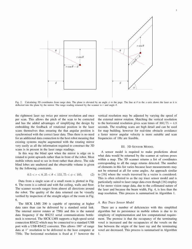
scanner. This displacement alters the range readings by a valuedependent on the angle of the mirror. The following equations,which reference the values indicated in Fig. 2, indicate theconversion between the r, θ and φ coordinates, measured bythe laser scanner, and 3D Cartesian coordinates.
x =
(r cos θ − d) cosφ+ dr sin θ
(r cos θ − d) sinφ
(1)
where the value d is the separation between the origin of thelaser scanner and the axis of the rotating mirror. The rangeand bearing as measured by the laser scanner are r and θ. Theangle of the plane to the horizontal introduced by reflectingthe laser ray from the rotating mirror in front of the scanner isindicated by φ. The frequency of angular position reports canbe adjusted by altering the number of teeth on the blockingwheel and by changing the gearing. A high angular positionupdate rate leads to better accuracy in that the system can
Stepper-motorDriver UCN5804
Stepper-motor
Divider12MHz Quartz
Crystal Oscillator
Fig. 3. Block diagram illustrating the electronic components of the 3D laserscanner.
respond faster to changes in angular velocity. However, missedcounts do still occur occasionally.
C. Enhanced 3D Laser Scanner
The laser scanner described above can be deployed tostandard mobile robots without any hardware modifications.Although it is very convenient, some relatively minor modifi-cations to the hardware of the standard mobile robotic platformbring about substantial improvements. The main features of theproposed design are:• Fig. 1 shows the enhanced 3D laser scanner is based on a
SICK LMS 200 [13] [14] [15] which is facing upwards.A rotating mirror driven by a stepper motor via a signalfrom a quartz crystal oscillator shown in Fig. 3.
• The high update rate (75Hz) of the LMS 200 meansthe 3D scanner delivers scans at 1Hz with a horizontalresolution of 1◦ and vertical resolution of 5◦.
• Accurate determination of mirror angle is paramount tothe accuracy of the 3D laser scanner.
• Finally the most difficult problem to address is that DCmotors used in this research have significant amounts ofbacklash.
A better approach which solves these problems is to drivethe mirror using a stepper motor directly coupled to themirror spindle. Stepper motors can be operated over a rangeof speeds and are especially suited to low speed operation.The stepper motor used in this research has a 1.8◦ angularresolution that is half-stepped to give 400 steps per revolu-tion. Although the stepper motor, when driven by a quartzcrystal oscillator signal, has an exceedingly consistent angularvelocity the mirror still needs to be approximately balanced.Significant off-centre mass distribution will cause flexing tooccur between the motor connection and the mirror. Thisflexing causes significant distortion in the scan data whichmay be reduced by using stiffer materials and balancing themirror to reduce the variation in load torque. Generally, thestepper motor mechanism is much less sensitive to variationsin load torque than the DC motor driven system.
A block diagram of the electronic components in Fig. 3illustrates how a 12MHz oscillator signal is stepped downto produce a highly stable and accurate 15ms clock signal.The clock signal drives the stepper-motor driver microchipwhich outputs the correct waveform for the stepper-motor. Thisconfiguration coupled with an adequately balanced rotatingmirror mechanism results in a very consistent rotation speedover an extended period of time.
The field of view is improved by placing the laser scannerfacing upwards, Fig. 1. The blocking arms affixed to themirror edges in Fig. 1 and Fig. 5 alter the range reading of
3
rco
sθ−
d
θ
φ
d
θ
r sin θ
d
r cos θ − d
r sin θ
Fig. 2. Calculating 3D coordinates from range data. The plane is elevated by an angle φ to the page. The line at θ to the x-axis shows the laser as it isdeflected into the plane by the mirror. The range reading returned by the scanner is r and angle θ.
the rightmost laser ray twice per mirror revolution and onceper scan. This allows the pitch of the scan to be correctedand has the added advantages of simplifying the design byembedding the feedback of rotational position in the laserscans themselves thus ensuring the that angular position issynchronised with the correct laser data. Thus there is no needfor an additional data connection to the host robot meaning thatexisting systems maybe augmented with the rotating mirrorvery easily as all the information required to construct the 3Dscans is in present in the laser range readings.
In this way the blind spot when the mirror is edge on isrotated to point upwards rather than in front of the robot. Mostmobile robots need to see in front rather than above. The sideblind lobes are unaltered and the observable volume is givenby the following constraints.
0.5 < r < 8, 25 < θ < 155, 75 < φ < 105, (2)
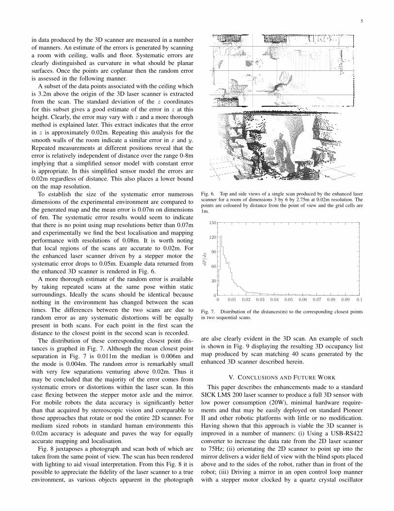
Data from a single scan of a small room is plotted in Fig.6. The room is a cuboid and with flat ceiling, walls and floor.The scanner records ranges from almost all directions aroundthe robot. The quality of the data returned can be visuallyverified by inspection of the straight edges of the room in Fig.6.
The SICK LMS 200 is capable of operating at higherdata rates than can be delivered by a standard serial link.The internal mirror rotates at 75Hz and this is the naturaldata frequency if the RS232 serial communications bottle-neck is removed. The SICK LMS supports a high-speed serialconnection RS422 which may be connected to a standard USBport with a USB-RS422 converter. This allows 180◦ of rangedata at 1◦ resolution to be delivered to the host computer at75Hz. The horizontal resolution is fixed at 1◦ however the
vertical resolution may be adjusted by varying the speed ofthe external mirror rotation. Matching the vertical resolutionto the horizontal resolution gives scan times of 360/75 = 4.8seconds. The resulting scans are high detail and can be usedfor map building, however for real-time obstacle avoidancea faster mirror angular velocity is more suitable and scanfrequencies of 1Hz are feasible.
III. 3D SENSOR MODEL
A sensor model is required to make predictions aboutwhat data would be returned by the scanner at various poseswithin a map. The 3D scanner returns a list of coordinatescorresponding to all the range returns detected. The numberof elements in this list varies because laser measurements maynot be returned at all for some angles. An approach similarto [16] where the voxels traversed by a vector is considered.This is often referred to as the ray trace sensor model and isparticularly suited to laser range data even though [16] employit for stereo vision range data, due to the collimated nature ofthe laser and because the beam width, Fig. 4, is less than themap resolution. This process is summarised in Algorithm 1.
A. Ray Trace Sensor Model
There are a number of deficiencies with this simplifiedalgorithm but its persistence in mobile robots is due to itssimplicity of implementation and low computational require-ment. The premise is that the occupancy of the terminatingvoxel is increased and the occupancies of the voxels on theline between the origin of the laser ray and the terminatingvoxel are decreased. This process is summarised in Algorithm1.
4
Algorithm 1 Ray trace sensor model.for all points in pointcloud do
calculate voxel from current point xif voxel is present in occupancy list then
increment terminating voxel’s occupied countelse
add voxel to occupancy listend ifdetermine number of steps along vector as |x|εfor all steps do
decrement occupied count of voxelif occupied count of current voxel is ≤ 0 then
remove voxel from occupancy listend if
end forend for
In this way, given a 3D map, pose and sensor model theexpected occupancy of voxels surrounding the pose can becalculated. The accuracy of the sensor model is dependentupon the errors in the data returned by the 3D laser scanner.The errors of the 3D laser range finder may be modelledas Gaussian in θ, φ and r. Complete differentiation of (1)produces the following expressions for the errors in x, y andz.
∆x = cosφ cos θ∆r − r cosφ sin θ∆θ− sinφ(r cos θ − d)∆φ+ (1− cosφ)∆d
∆y =∆r sin θ + r cos θ∆θ∆z = cos θ sinφ∆r − r sin θ sinφ∆θ
− sinφ∆d+ r cos θ cosφ∆φ− d cosφ∆φ
Converting from the spherical polar coordinate to theCartesian coordinate system produces errors that are linearlydependent on the distance from the origin. This is superior tothe quadratic dependence found in triangulation techniques.This spread in uncertainty is useful for inclusion in the sensormodel. The unmodified 2D scanner is capable of readingranges up to 80m. Such large distances are infrequentlyobserved in indoor environments however and as the errorscales linearly with range the accuracy of these long rangereadings is poor. To ease the complexity of the sensor modelthe readings are truncated to 8m and the upper bound of theerror, namely that at 8m, is assumed for all remaining rangereadings. This error is then intrinsically incorporated into thesensor model by limiting the map resolution to this value.
B. Pixel Mixing
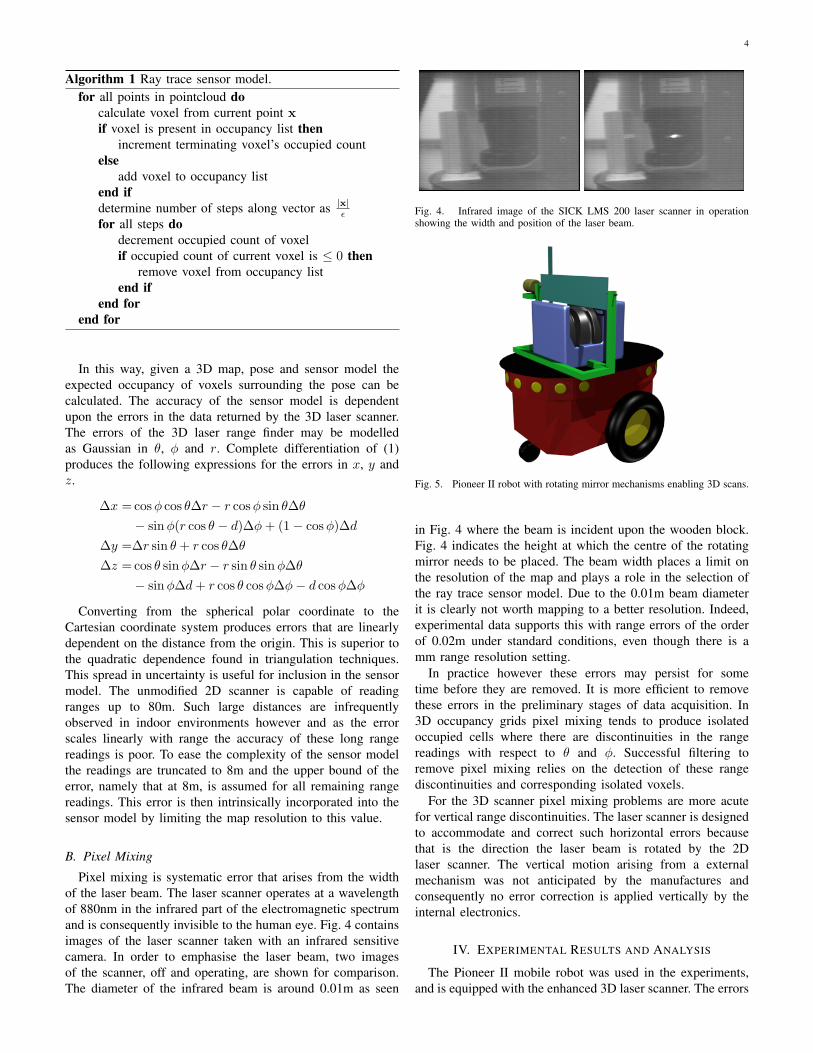
Pixel mixing is systematic error that arises from the widthof the laser beam. The laser scanner operates at a wavelengthof 880nm in the infrared part of the electromagnetic spectrumand is consequently invisible to the human eye. Fig. 4 containsimages of the laser scanner taken with an infrared sensitivecamera. In order to emphasise the laser beam, two imagesof the scanner, off and operating, are shown for comparison.The diameter of the infrared beam is around 0.01m as seen
Fig. 4. Infrared image of the SICK LMS 200 laser scanner in operationshowing the width and position of the laser beam.
Fig. 5. Pioneer II robot with rotating mirror mechanisms enabling 3D scans.
in Fig. 4 where the beam is incident upon the wooden block.Fig. 4 indicates the height at which the centre of the rotatingmirror needs to be placed. The beam width places a limit onthe resolution of the map and plays a role in the selection ofthe ray trace sensor model. Due to the 0.01m beam diameterit is clearly not worth mapping to a better resolution. Indeed,experimental data supports this with range errors of the orderof 0.02m under standard conditions, even though there is amm range resolution setting.
In practice however these errors may persist for sometime before they are removed. It is more efficient to removethese errors in the preliminary stages of data acquisition. In3D occupancy grids pixel mixing tends to produce isolatedoccupied cells where there are discontinuities in the rangereadings with respect to θ and φ. Successful filtering toremove pixel mixing relies on the detection of these rangediscontinuities and corresponding isolated voxels.
For the 3D scanner pixel mixing problems are more acutefor vertical range discontinuities. The laser scanner is designedto accommodate and correct such horizontal errors becausethat is the direction the laser beam is rotated by the 2Dlaser scanner. The vertical motion arising from a externalmechanism was not anticipated by the manufactures andconsequently no error correction is applied vertically by theinternal electronics.
IV. EXPERIMENTAL RESULTS AND ANALYSIS
The Pioneer II mobile robot was used in the experiments,and is equipped with the enhanced 3D laser scanner. The errors
5
in data produced by the 3D scanner are measured in a numberof manners. An estimate of the errors is generated by scanninga room with ceiling, walls and floor. Systematic errors areclearly distinguished as curvature in what should be planarsurfaces. Once the points are coplanar then the random erroris assessed in the following manner.
A subset of the data points associated with the ceiling whichis 3.2m above the origin of the 3D laser scanner is extractedfrom the scan. The standard deviation of the z coordinatesfor this subset gives a good estimate of the error in z at thisheight. Clearly, the error may vary with z and a more thoroughmethod is explained later. This extract indicates that the errorin z is approximately 0.02m. Repeating this analysis for thesmooth walls of the room indicate a similar error in x and y.Repeated measurements at different positions reveal that theerror is relatively independent of distance over the range 0-8mimplying that a simplified sensor model with constant erroris appropriate. In this simplified sensor model the errors are0.02m regardless of distance. This also places a lower boundon the map resolution.
To establish the size of the systematic error numerousdimensions of the experimental environment are compared tothe generated map and the mean error is 0.07m on dimensionsof 6m. The systematic error results would seem to indicatethat there is no point using map resolutions better than 0.07mand experimentally we find the best localisation and mappingperformance with resolutions of 0.08m. It is worth notingthat local regions of the scans are accurate to 0.02m. Forthe enhanced laser scanner driven by a stepper motor thesystematic error drops to 0.05m. Example data returned fromthe enhanced 3D scanner is rendered in Fig. 6.
A more thorough estimate of the random error is availableby taking repeated scans at the same pose within staticsurroundings. Ideally the scans should be identical becausenothing in the environment has changed between the scantimes. The differences between the two scans are due torandom error as any systematic distortions will be equallypresent in both scans. For each point in the first scan thedistance to the closest point in the second scan is recorded.
The distribution of these corresponding closest point dis-tances is graphed in Fig. 7. Although the mean closest pointseparation in Fig. 7 is 0.011m the median is 0.006m andthe mode is 0.004m. The random error is remarkably smallwith very few separations venturing above 0.02m. Thus itmay be concluded that the majority of the error comes fromsystematic errors or distortions within the laser scan. In thiscase flexing between the stepper motor axle and the mirror.For mobile robots the data accuracy is significantly betterthan that acquired by stereoscopic vision and comparable tothose approaches that rotate or nod the entire 2D scanner. Formedium sized robots in standard human environments this0.02m accuracy is adequate and paves the way for equallyaccurate mapping and localisation.
Fig. 8 juxtaposes a photograph and scan both of which aretaken from the same point of view. The scan has been renderedwith lighting to aid visual interpretation. From this Fig. 8 it ispossible to appreciate the fidelity of the laser scanner to a trueenvironment, as various objects apparent in the photograph
Fig. 6. Top and side views of a single scan produced by the enhanced laserscanner for a room of dimensions 3 by 6 by 2.75m at 0.02m resolution. Thepoints are coloured by distance from the point of view and the grid cells are1m.
0
30
60
90
120
150
dP
/dx
0 0.01 0.02 0.03 0.04 0.05 0.06 0.07 0.08 0.09 0.1
Fig. 7. Distribution of the distances(m) to the corresponding closest pointsin two sequential scans.
are alse clearly evident in the 3D scan. An example of suchis shown in Fig. 9 displaying the resulting 3D occupancy listmap produced by scan matching 40 scans generated by theenhanced 3D scanner described herein.
V. CONCLUSIONS AND FUTURE WORK
This paper describes the enhancements made to a standardSICK LMS 200 laser scanner to produce a full 3D sensor withlow power consumption (20W), minimal hardware require-ments and that may be easily deployed on standard PioneerII and other robotic platforms with little or no modification.Having shown that this approach is viable the 3D scanner isimproved in a number of manners: (i) Using a USB-RS422converter to increase the data rate from the 2D laser scannerto 75Hz; (ii) orientating the 2D scanner to point up into themirror delivers a wider field of view with the blind spots placedabove and to the sides of the robot, rather than in front of therobot; (iii) Driving a mirror in an open control loop mannerwith a stepper motor clocked by a quartz crystal oscillator

6
Fig. 8. Photograph and 3D scan of mapped room from the same point ofview. Blue regions correspond to areas with no returned scan.
Fig. 9. Corridor view demonstrating a sequence of scan matched 3D scans.The green spheres are the observation positions and the map voxels arecoloured by height.
clock signal, which has a negligible impact on the accuracyof the 2D laser scanner over the 0 to 8m range resulting inan error of 0.02m. In this way almost omni-directional 3Dscans consisting of up to 5000 data points are delivered to therobot’s computer at a configurable 1Hz.
Our further research will deal with the representation andprocessing of this data in a localisation and mapping context.Repeated scanning from a fixed position may be used todetermine the short term dynamic profile of an environment. Ifthere are people moving, these will be detected as differences
between successive scans and removed. An intensive fieldtesting of the developed 3D laser scanner will be carried outin both indoor and outdoor environments.
REFERENCES
[1] K. Lingemann, H. Surmann, A. Nuchter, and J. Hertzberg,“Indoor and outdoor localization for fast mobile robots,” inProc. of the IEEE/RSJ Int. Conf. on Intelligent Robots andSystems, Sendai, Japan, Sep. 2004, pp. 2185–2190.
[2] A. Nuchter, K. Lingemann, J. Hertzberg, and H. Surmann,“Heuristic-based laser scan matching for outdoor 6D SLAM,” inAdvances in Artificial Intelligence. 28th annual German Conf.on AI, Sep. 2005.
[3] D. Cole and P. Newman, “Using laser range data for 3D slamin outdoor environments,” in Robotics and Automation, 2006.ICRA 2006. Proceedings 2006 IEEE International Conferenceon, May 15-19, 2006, pp. 1556–1563.
[4] P. Pfaff, R. Triebel, and W. Burgard, “An efficient extension toelevation maps for outdoor terrain mapping and loop closing,”The Int. Journal of Robotics Research, vol. 26, no. 2, pp. 217–230, 2007.
[5] A. Howard, D. F. Wolf, and G. S. Sukhatme, “Towards 3Dmapping in large urban environments,” in IEEE/RSJ Int. Conf.on Intelligent Robots and Systems, Sendai, Japan, Sep. 2004,pp. 419–424.
[6] M. Montemerlo and S. Thrun, “Large-scale robotic 3D map-ping of urban structures,” in Proc. of the Int. Symposium onExperimental Robotics (ISER), 2004.
[7] A. Howard, A. Parker, E. Lynne, and G. S. Sukhatme, “TheSDR experience: Experiments with a large-scale heterogenousmobile robot team (extended abstract),” Int. Symposium onExperimental Robotics, Jun. 2004.
[8] D. Hahnel, D. Schulz, and W. Burgard, “Map building withmobile robots in populated environments,” in Proc. of theIEEE/RSJ Int. Conf. on Intelligent Robots and Systems (IROS),2002.
[9] W. Jeong and K. Lee, “CV-SLAM: A new ceiling vision-basedSLAM technique,” in IEEE/RSJ Int. Conf. on Intelligent Robotsand Systems, 2005.
[10] W. Burgard, A. B. Cremers, D. Fox, D. Hahnel, G. Lakemeyer,D. Schulz, W. Steiner, and S. Thrun, “Experiences with aninteractive museum tour-guide robot,” Artificial Intelligence,vol. 114, no. 1–2, pp. 3–55, 1999.
[11] O. Wulf, K. O. Arras, H. I. Christensen, and B. Wagner, “2Dmapping of cluttered indoor environments by means of 3D per-ception,” in IEEE/RAS Int. Conf. on Robotics and Automation(ICRA), New Orleans, USA, 26 Apr. 2004.
[12] M. Walther, P. Steinhaus, and R. Dillmann, “A foveal 3Dlaser scanner integrating texture into range data,” in IntelligentAutonomous Systems 9, 2006.
[13] J. Ryde and H. Hu, “Laser based simultaneous mutual locali-sation for multiple mobile robots,” in Proc. of IEEE Int. Conf.on Mechatronics and Automation, Niagara Falls, Canada, Jul.2005, pp. 404–409.
[14] ——, “Mutual localization and 3D mapping by cooperativemobile robots,” in Proc. of Int. Conf. on Intelligent AutonomousSystems, The University of Tokyo, Tokyo, Japan, Mar. 2006.
[15] ——, “Cooperative mutual 3D laser mapping and localization,”in IEEE Int. Conf. on Robotics and Biomimetics, Kunming,China, Dec. 2006.
[16] R. Rocha, J. Dias, and A. Carvalho, “Cooperative multi-robotsystems: a study of vision-based 3-D mapping using informationtheory,” Robotics and Autonomous Systems, vol. 53, no. 3-4, pp.282–311, 31 Dec. 2005.