3d maya.pdf
DESCRIPTION
3D MAYATRANSCRIPT

3D MAYA
(for beginner)
FLYING BUTTERFLY ANIMATION - TUTORIAL FOR BEGINNERS
In this tutorial, we will make a simple butterfly and animate it.
Figure 1. Click here to view larger image.
Step 1
Start Maya. Go to Side view. Select EP Curve tool.
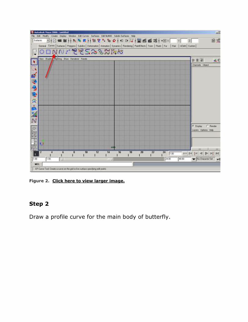
Figure 2. Click here to view larger image.
Step 2
Draw a profile curve for the main body of butterfly.

Figure 3. Click here to view larger image.
Step 3
Right-click on the Curve and select Vertex mode.
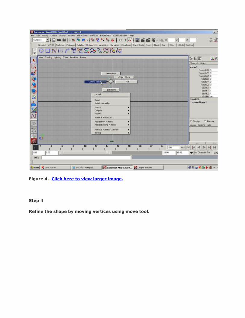
Figure 4. Click here to view larger image.
Step 4
Refine the shape by moving vertices using move tool.

Figure 5. Click here to view larger image.
Step 5
Make sure “Surfeces” menu-set is selected („F4‟ is shortcut for Surface menu-set).
While the curve is still selected, go to Surfaces > Revolve.

Figure 6. Click here to view larger image.
Step 6
You will get the geometry for the main body like below.
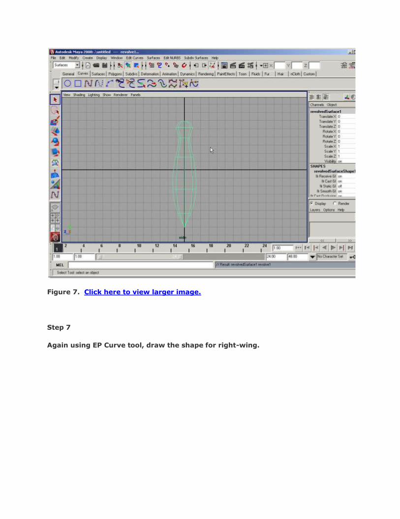
Figure 7. Click here to view larger image.
Step 7
Again using EP Curve tool, draw the shape for right-wing.
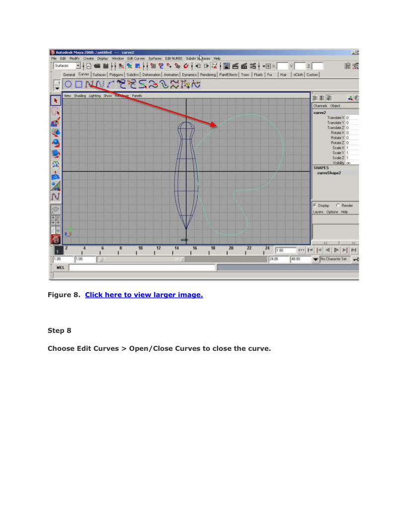
Figure 8. Click here to view larger image.
Step 8
Choose Edit Curves > Open/Close Curves to close the curve.

Figure 9. Click here to view larger image.
Step 9
Click Surfaces > Planar.
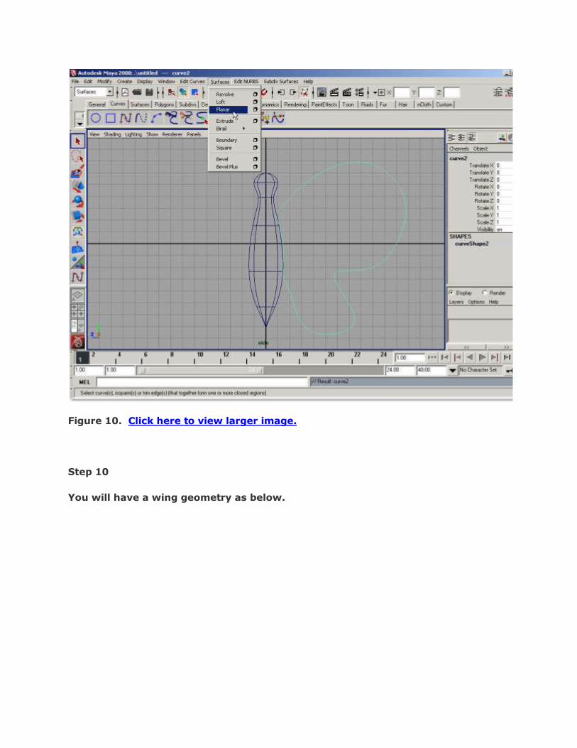
Figure 10. Click here to view larger image.
Step 10
You will have a wing geometry as below.

Figure 11. Click here to view larger image.
Step 11
To see it at smooth level -3, press „3‟.

Figure 12. Click here to view larger image.
Step 12
Right-click on the wing curve. Go to vertex mode and move vertices to reshape the
wing as you want.
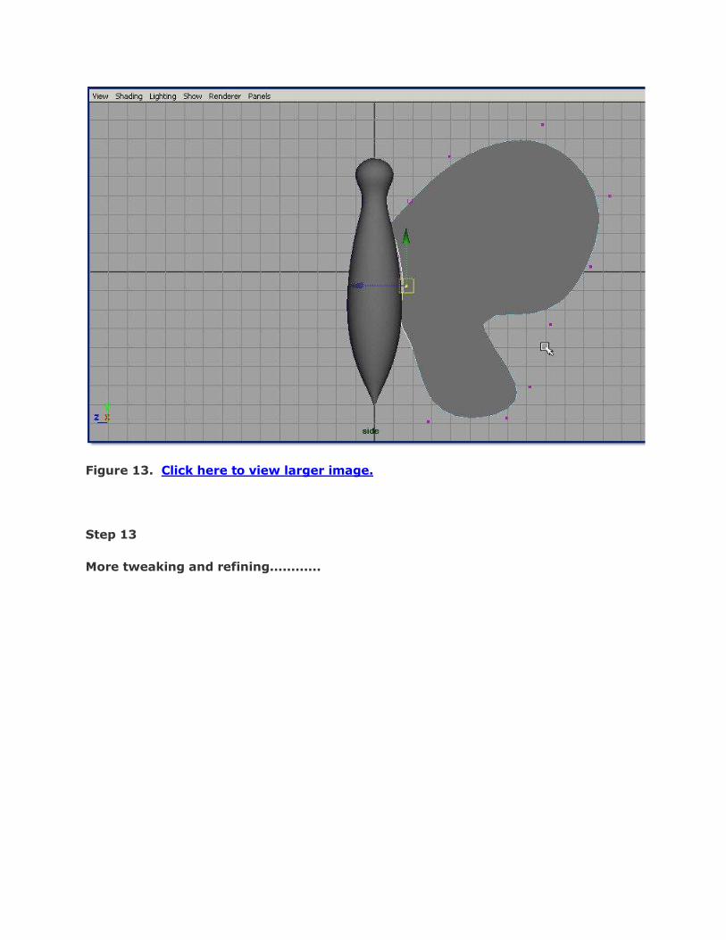
Figure 13. Click here to view larger image.
Step 13
More tweaking and refining............

Figure 14. Click here to view larger image.
Step 14
For rotating (Flapping) purpose of the wings we should place the Pivot at
appropriate place so that it can rotate around the proper center. So, Select the
wing surface and press INSERT to Pivot editing mode and move the Pivot as
shown below

Figure 15. Click here to view larger image.
Step 15
Press INSERT again to exit the Pivot editing mode. We do not need the profile
curves for body and wing anymore. So it‟s a good idea to delete the History at this
stage. Click Delete by Type > History

Figure 16. Click here to view larger image.
Step 16
To get the left wing, select the right wing and choose Edit menu and click the
Option box icon for Duplicate Special command.
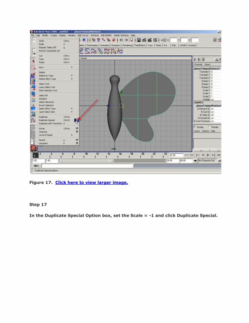
Figure 17. Click here to view larger image.
Step 17
In the Duplicate Special Option box, set the Scale = -1 and click Duplicate Special.

Figure 18. Click here to view larger image.
Step 18
Move the wing to the left so it is placed in the appropriate place.
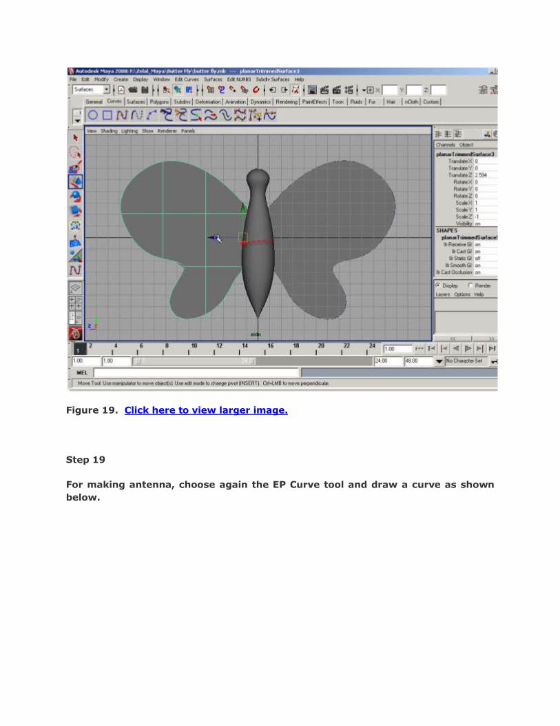
Figure 19. Click here to view larger image.
Step 19
For making antenna, choose again the EP Curve tool and draw a curve as shown
below.
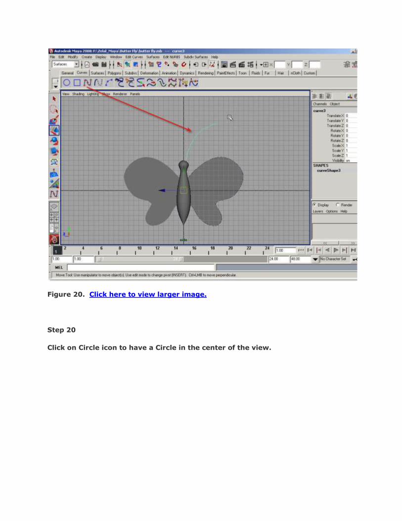
Figure 20. Click here to view larger image.
Step 20
Click on Circle icon to have a Circle in the center of the view.

Figure 21. Click here to view larger image.
Step 21
Move the circle up as show below. Then SHIFT+Click the antenna curve.
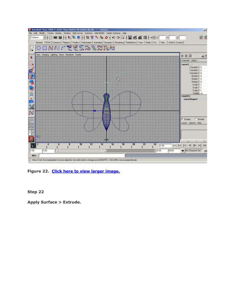
Figure 22. Click here to view larger image.
Step 22
Apply Surface > Extrude.

Figure 23. Click here to view larger image.
Step 23
You will get a extruded shape for the antenna geometry. But it‟s not in the proper
place and also we do not want to have so thick antenna.
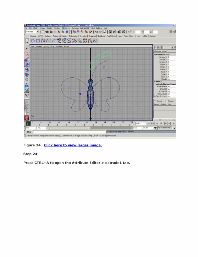
Figure 24. Click here to view larger image.
Step 24
Press CTRL+A to open the Attribute Editor > extrude1 tab.

Figure 25. Click here to view larger image.
Step 25
In the Extrude History group, select “Component Pivot” as Use Component Pivot
type. Check “Fixed Path” option. Make sure other option “Use Profile Normal” is
also checked.

Figure 26. Click here to view larger image.
Step 26
Now, select the circle again and under Attribute Editor > makeNurbCircle1, set the
radius = 0.1 or even lower value.

Figure 27. Click here to view larger image.
Step 27
Again under extrude1 tab, set the Scale = 0.0 in the Extrude History parameters
group.
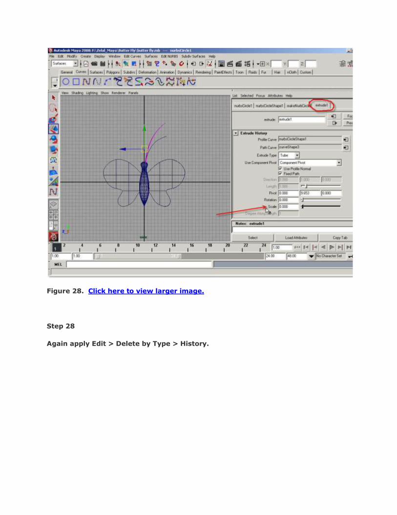
Figure 28. Click here to view larger image.
Step 28
Again apply Edit > Delete by Type > History.
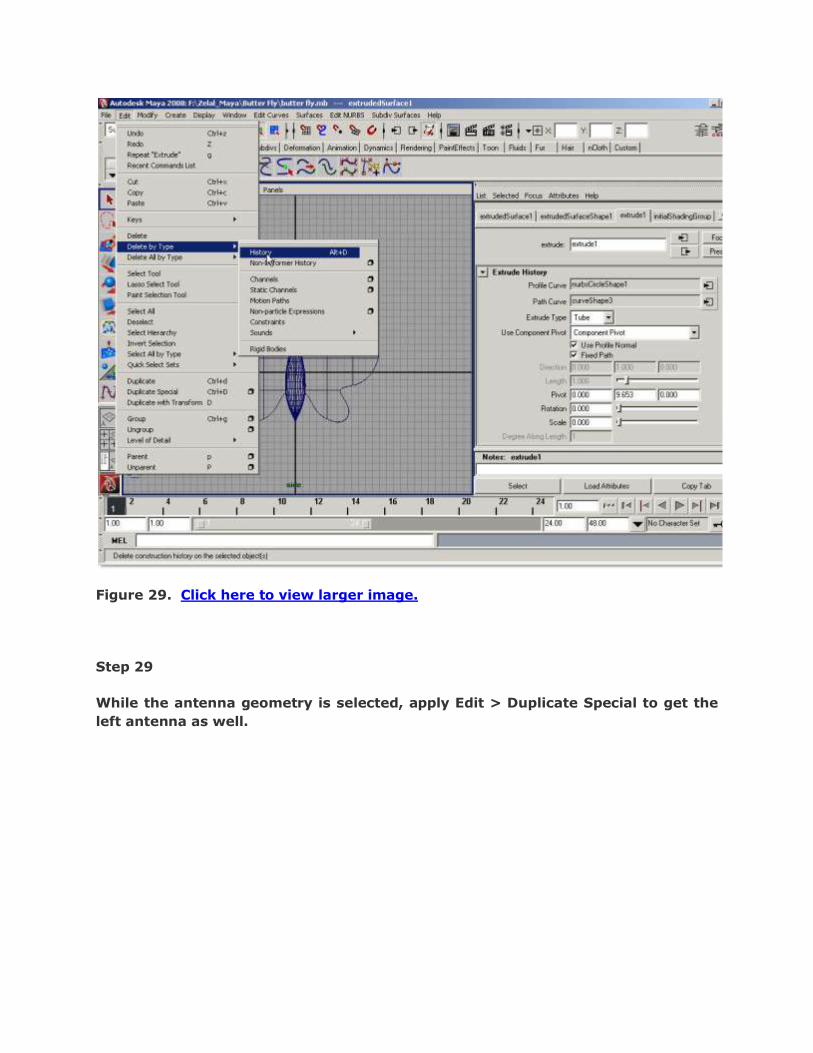
Figure 29. Click here to view larger image.
Step 29
While the antenna geometry is selected, apply Edit > Duplicate Special to get the
left antenna as well.

Figure 30. Click here to view larger image.
Step 30
We do not need the curves now. So, choose Window > Outliner.
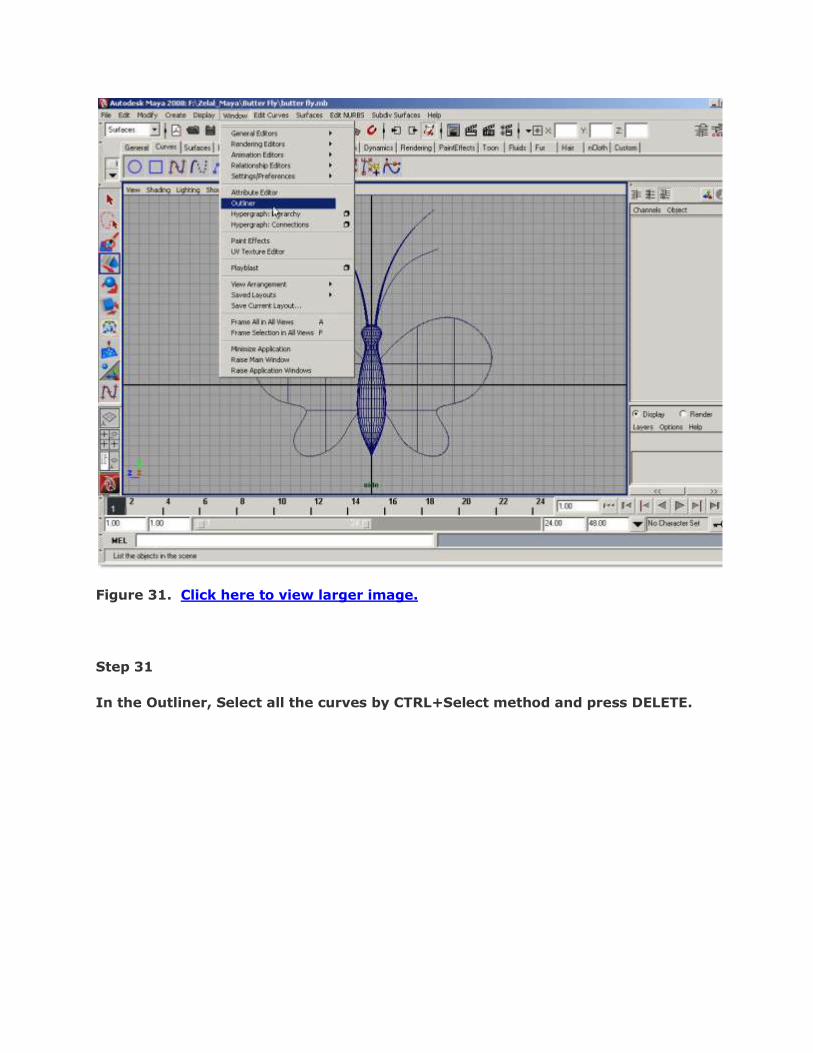
Figure 31. Click here to view larger image.
Step 31
In the Outliner, Select all the curves by CTRL+Select method and press DELETE.

Figure 32. Click here to view larger image.
Step 32
Now there is no unnecessary curves in our scene.

Figure 33. Click here to view larger image.
Step 33
Select the middle main body and change the name of it to “main body” in the
channel box.

Figure 34. Click here to view larger image.
Step 34
Rename the body‟s other individual parts as well.
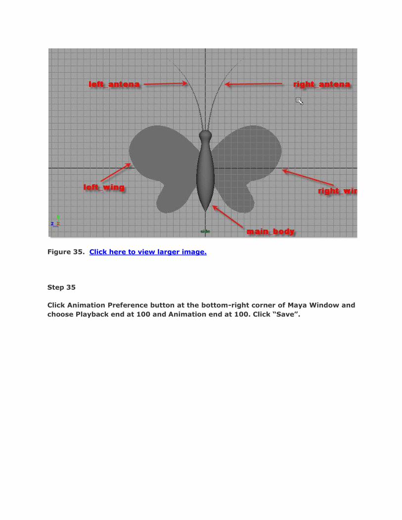
Figure 35. Click here to view larger image.
Step 35
Click Animation Preference button at the bottom-right corner of Maya Window and
choose Playback end at 100 and Animation end at 100. Click “Save”.

Figure 36. Click here to view larger image.
Step 36
We will now make the hierarchy for the body as we want all wings and antennas
to be driven with the main body. For this, select the right wing and then
SHIFT+Select the main body. Press „P‟ to make the main body as parent of the
right-wing. Repeat the same for other three parts as well.
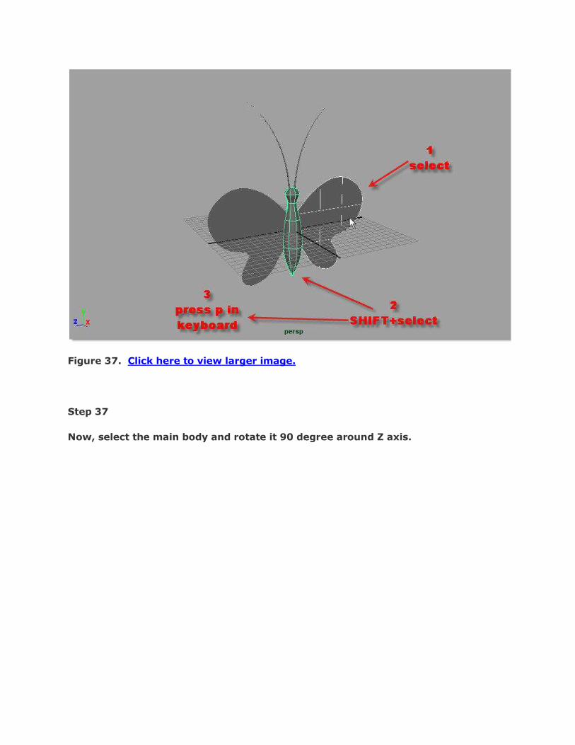
Figure 37. Click here to view larger image.
Step 37
Now, select the main body and rotate it 90 degree around Z axis.

Figure 38. Click here to view larger image.
Step 38
Select the left wing and choose Modify > Freeze Transformations. It will not lock
the transformations, but it will neutralize the present transforms value to Zero so
that we can rotate or move it starting from 0 (zero). Do the same for right wing as
well.
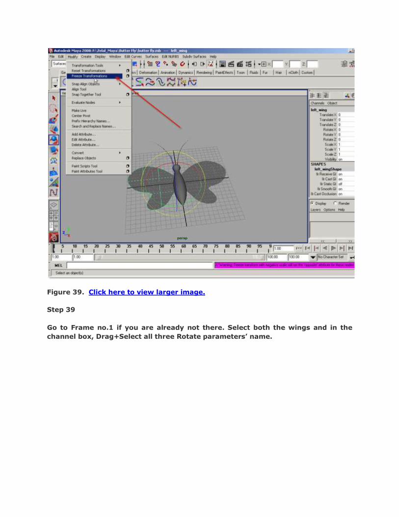
Figure 39. Click here to view larger image.
Step 39
Go to Frame no.1 if you are already not there. Select both the wings and in the
channel box, Drag+Select all three Rotate parameters‟ name.
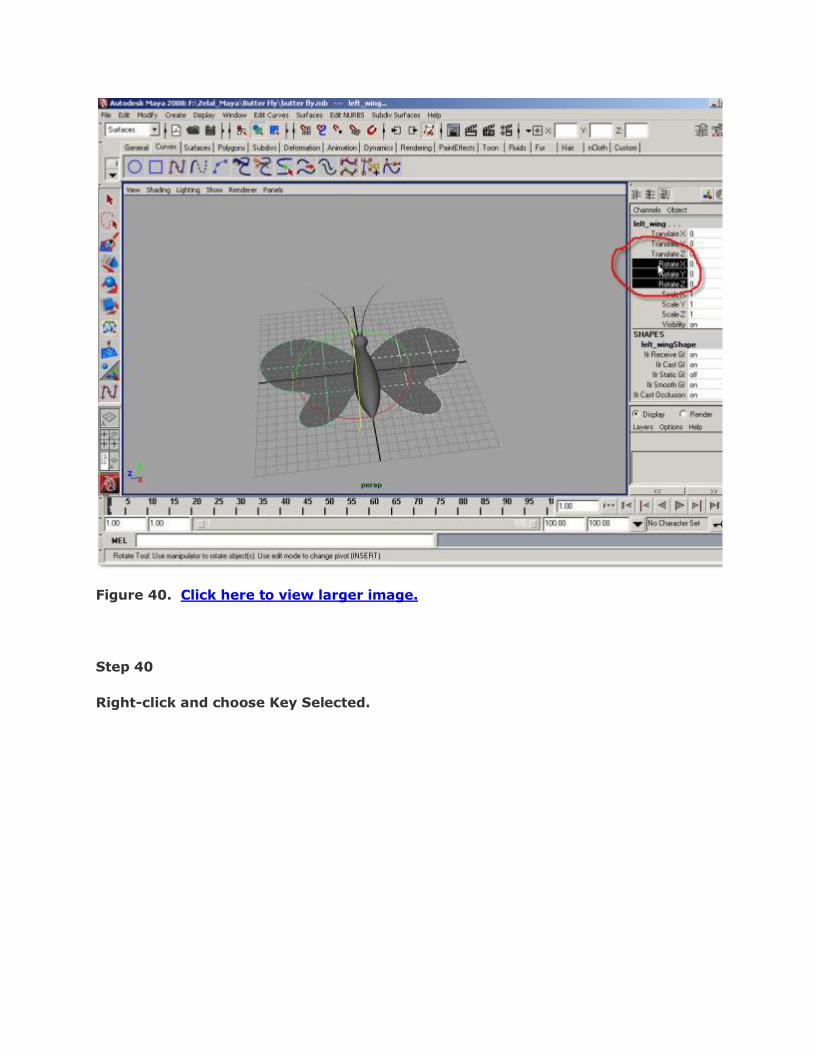
Figure 40. Click here to view larger image.
Step 40
Right-click and choose Key Selected.

Figure 41. Click here to view larger image.
Step 41
Select the right wing. Click “Auto Keyframe Toggle” button. It will turn red to
indicate that auto-keyframing active. Go to frame no. 5.

Figure 42. Click here to view larger image.
Step 42
Rotate the wing -45 degree around Y axis. Now a keyframe is automatically set at
frame no.5 for the right wing.
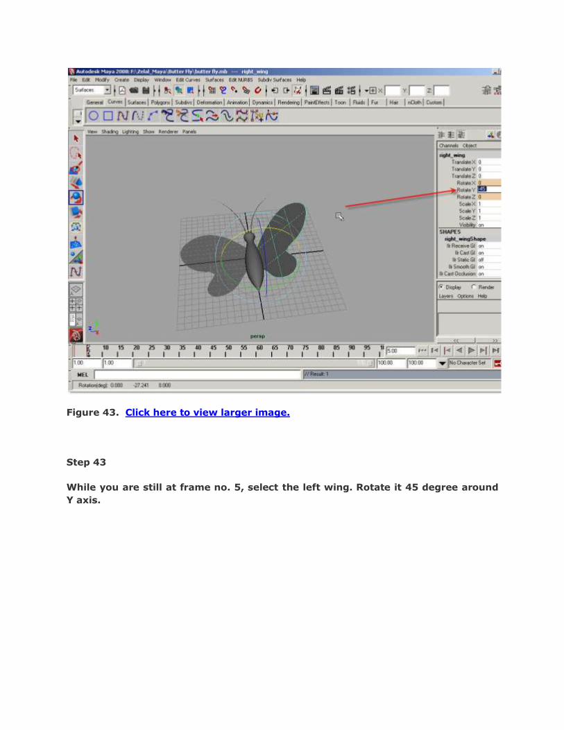
Figure 43. Click here to view larger image.
Step 43
While you are still at frame no. 5, select the left wing. Rotate it 45 degree around
Y axis.

Figure 44. Click here to view larger image.
Step 44
Go to frame no. 10 and set the Y rotations back at 0 for both the wings.
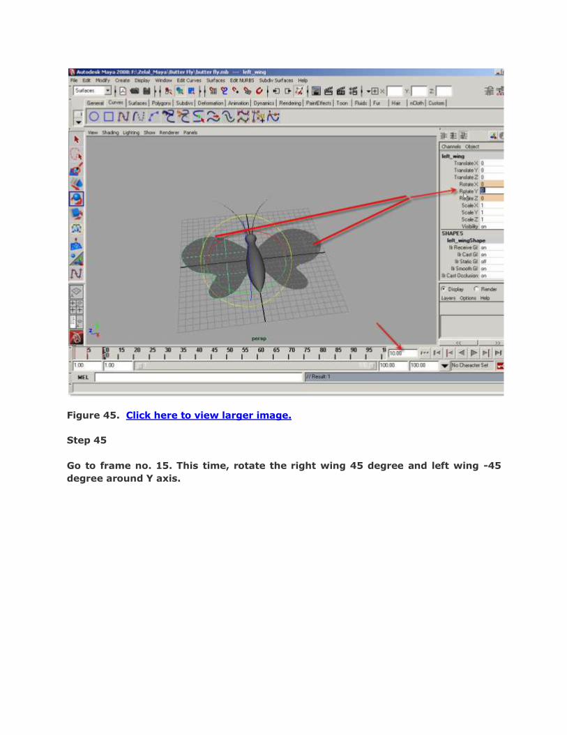
Figure 45. Click here to view larger image.
Step 45
Go to frame no. 15. This time, rotate the right wing 45 degree and left wing -45
degree around Y axis.

Figure 46. Click here to view larger image.
Step 46
Go to frame no. 20 and set the Y rotation for both the wings back at 0 degree.

Figure 47. Click here to view larger image.
Step 47
We have got a single-loop animation from 0 – 20 frames for both the wings. We
will make this animation to be repeated all the way of the animation using Graph
Editor. Select the right wing. Choose Window > Animation Editors > Graph Editor.

Figure 48. Click here to view larger image.
Step 48
You will see a sine wave against “Rotate Y” in the Graph Editor window.

Figure 49. Click here to view larger image.
Step 49
Choose Curves > Post Infinity > Cycle.

Figure 50. Click here to view larger image.
Step 50
To get the infinity graph visible apply View > Infinity.

Figure 51. Click here to view larger image.
Step 51
Then zoom-out by ALT+Right-mouse Drag in the graph window to see the. You will
see the infinite sine wave of looped animation for the right wing.
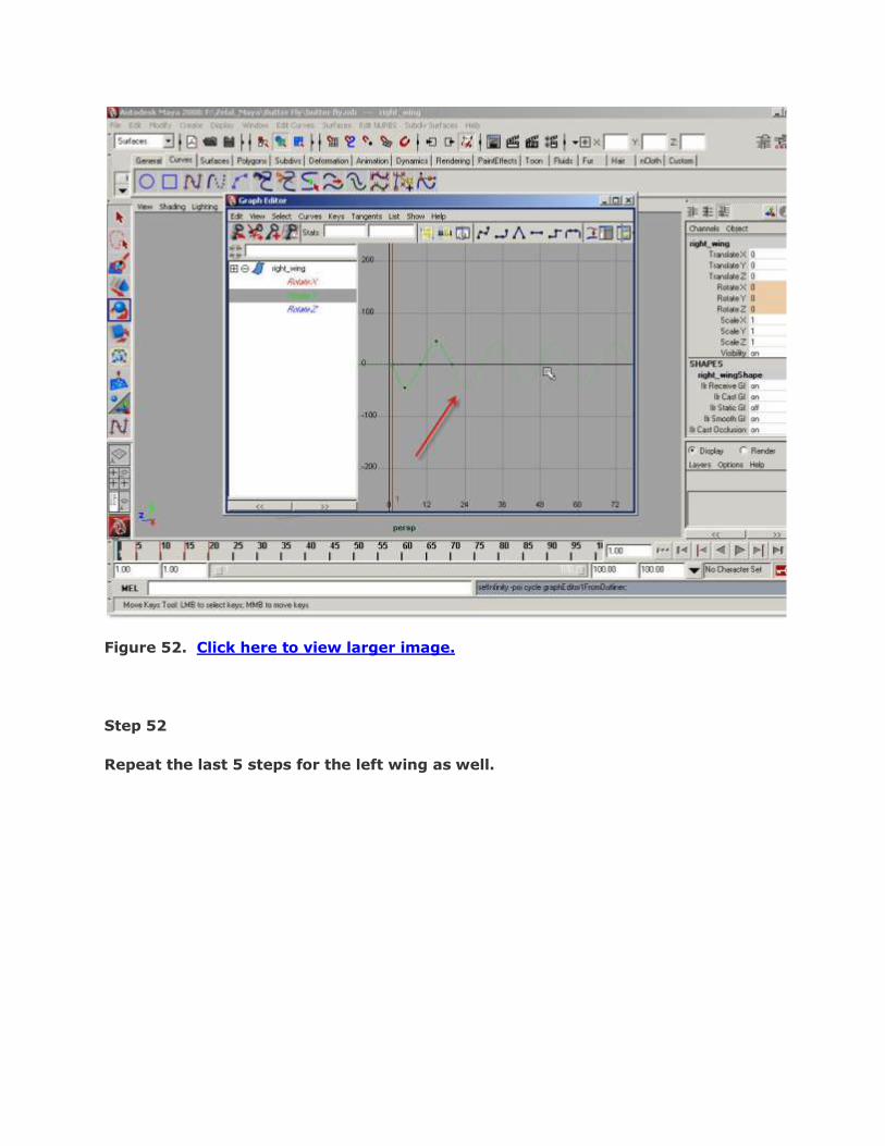
Figure 52. Click here to view larger image.
Step 52
Repeat the last 5 steps for the left wing as well.
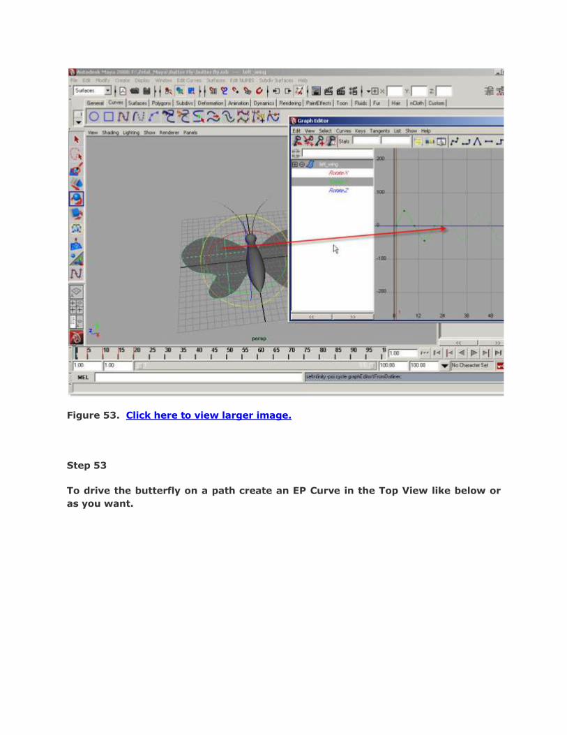
Figure 53. Click here to view larger image.
Step 53
To drive the butterfly on a path create an EP Curve in the Top View like below or
as you want.
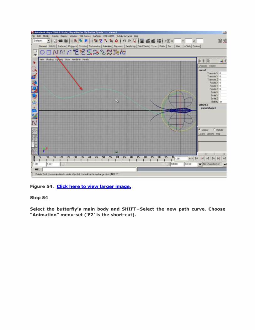
Figure 54. Click here to view larger image.
Step 54
Select the butterfly‟s main body and SHIFT+Select the new path curve. Choose
“Animation” menu-set („F2‟ is the short-cut).
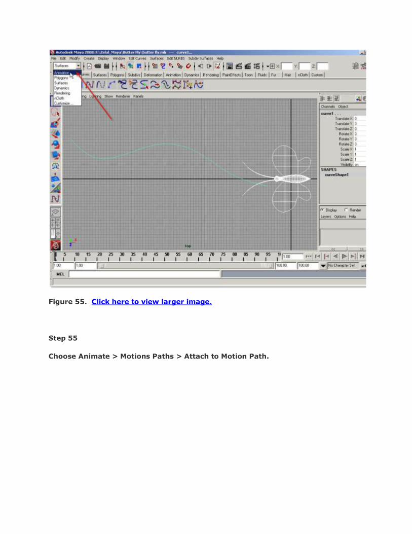
Figure 55. Click here to view larger image.
Step 55
Choose Animate > Motions Paths > Attach to Motion Path.
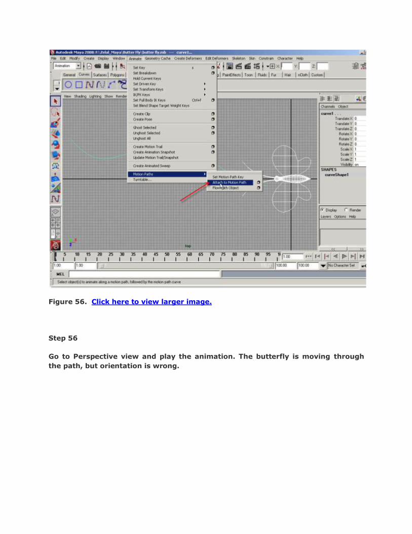
Figure 56. Click here to view larger image.
Step 56
Go to Perspective view and play the animation. The butterfly is moving through
the path, but orientation is wrong.

Figure 57. Click here to view larger image.
Step 57
To correct this problem, we have to edit Motion Path Attributes. Open the
Attributes Editor and under “motionPath1” tab, set the Front Axis = Y and Up Axis
= X in the Motion Path Attributes group.
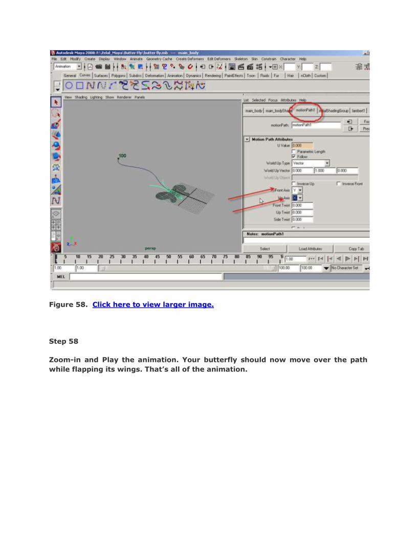
Figure 58. Click here to view larger image.
Step 58
Zoom-in and Play the animation. Your butterfly should now move over the path
while flapping its wings. That‟s all of the animation.

Figure 59. Click here to view larger image.

BURNING ROPE IN AUTODESK MAYA - TUTORIAL FOR BEGINNERS
Hi, and welcome back, I hope you liked the tutorial that I created on
basic materials. This time I am going to show you how to create an
basic and simple animation in Maya. The topic would be create a
burning rope and the final result would be as shown below.
Burning Rope Animation. Click here to view larger image.
Step One
In this tutorial, we will make an animation of simple burning rope.
Let’s start with making a profile for the rope. Click EP Curve

creation icon.
Figure 2. Click here to view larger image.
Step Two
Then in the Side viewport, draw a curve line as shown below or as
your wish.

Figure 3. Click here to view larger image.
Step Three
Choose “Rendering” menu-set from the Menu-set drop down list
located at the top-left corner of the Maya window.

Figure 3. Click here to view larger image.
Step Four
Select the curve we have just drawn (if it is not selected). Then choose Window >
General Editors > Visor.
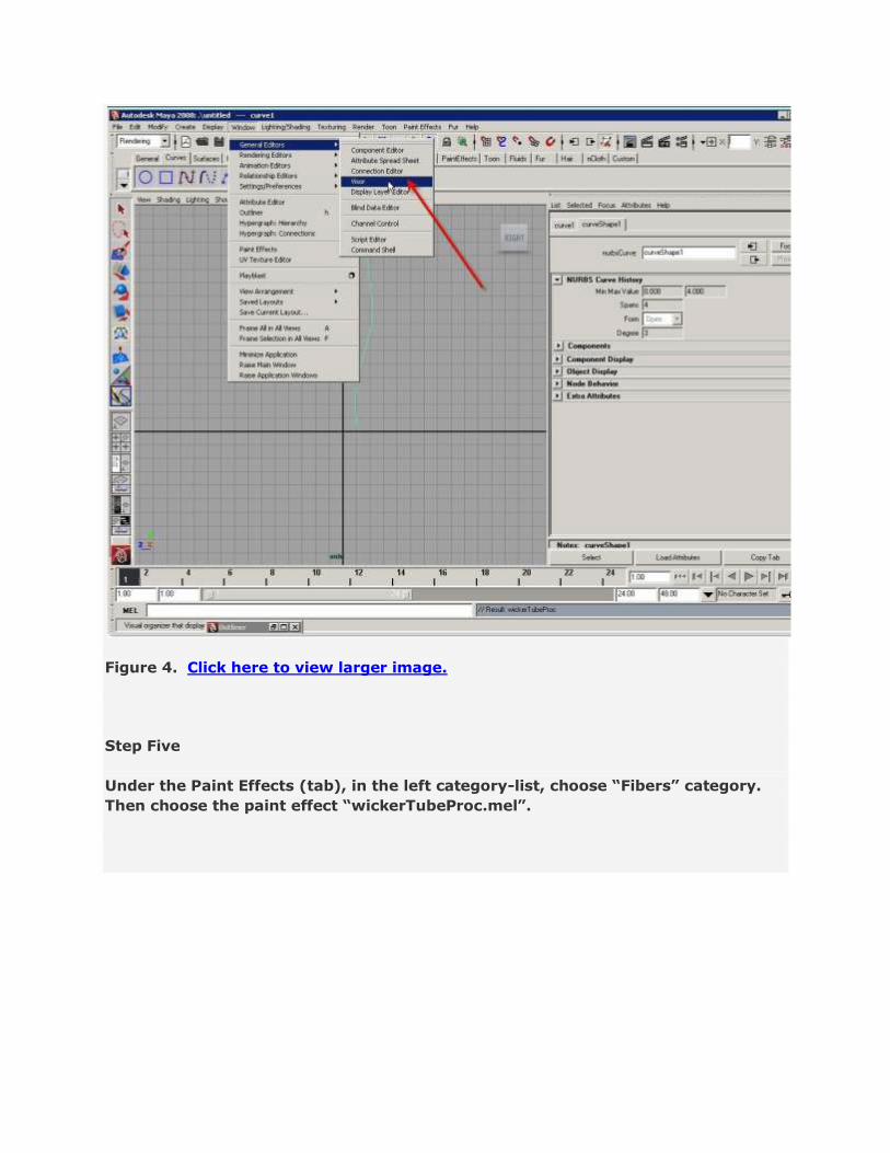
Figure 4. Click here to view larger image.
Step Five
Under the Paint Effects (tab), in the left category-list, choose “Fibers” category.
Then choose the paint effect “wickerTubeProc.mel”.

Figure 5. Click here to view larger image.
Step Six
Make sure, the curve is still selected in the view. Choose Paint Effects > Curve
Utilities > Attach Brush to Curves.

Figure 6. Click here to view larger image.
Step Seven
The rope-like fiber paint effect is now prolonged through the curve. Thus it got the
fiber rope shape.

Figure 7. Click here to view larger image.
Step Eight
Click “Render Current Frame” icon. You will see a pretty nice rope image rendered.

Figure 8. Click here to view larger image.
Step Nine
Set the animation/playback end frame to 100.
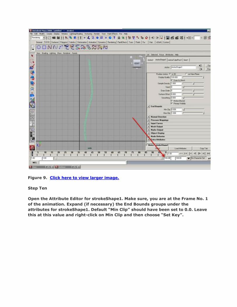
Figure 9. Click here to view larger image.
Step Ten
Open the Attribute Editor for strokeShape1. Make sure, you are at the Frame No. 1
of the animation. Expand (if necessary) the End Bounds groups under the
attributes for strokeShape1. Default “Min Clip” should have been set to 0.0. Leave
this at this value and right-click on Min Clip and then choose “Set Key”.
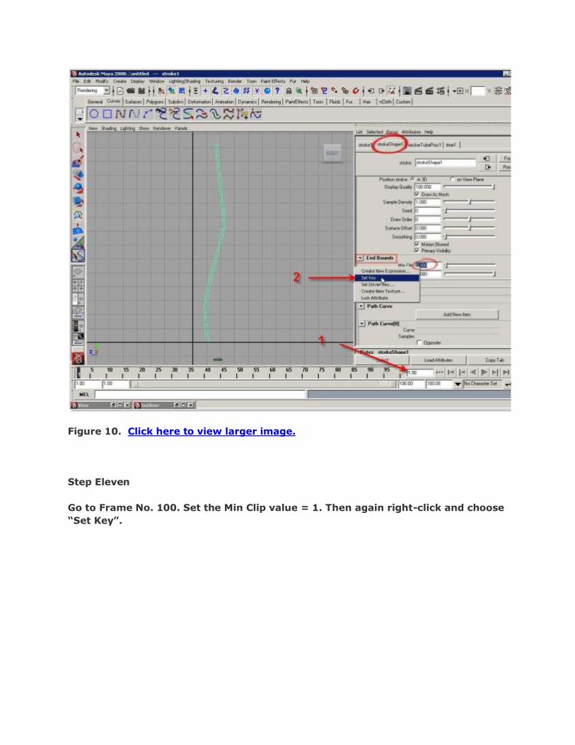
Figure 10. Click here to view larger image.
Step Eleven
Go to Frame No. 100. Set the Min Clip value = 1. Then again right-click and choose
“Set Key”.

Figure 11. Click here to view larger image.
Step Twelve
Play the animation and notice any frame (for example frame no. 29).

Figure 12. Click here to view larger image.
Step Thirteen
Render the view at Frame No. 1. See the result.

Figure 13. Click here to view larger image.
Step Fourteen
Render Frame No. 99 and see the result. You will see that the rope is going to be
exhausted at the end of the animation. This is what we want exactly for the rope.
But where is that fire which is burning this rope? Let‟s make that fire.
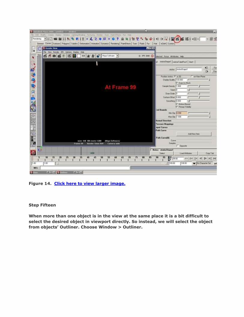
Figure 14. Click here to view larger image.
Step Fifteen
When more than one object is in the view at the same place it is a bit difficult to
select the desired object in viewport directly. So instead, we will select the object
from objects‟ Outliner. Choose Window > Outliner.

Figure 15. Click here to view larger image.
Step Sixteen
In the Outliner window, you will see 3 items are listed other than the default items
and “Stroke1” is highlighted as this was the last selected object.
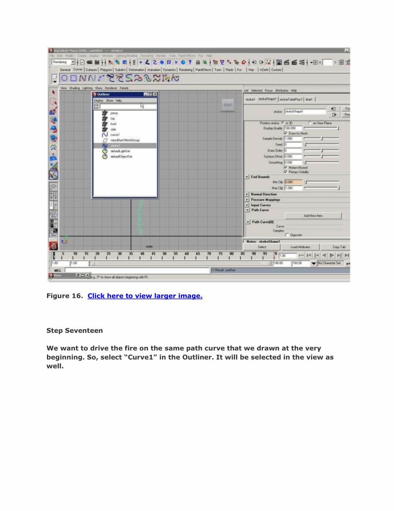
Figure 16. Click here to view larger image.
Step Seventeen
We want to drive the fire on the same path curve that we drawn at the very
beginning. So, select “Curve1” in the Outliner. It will be selected in the view as
well.
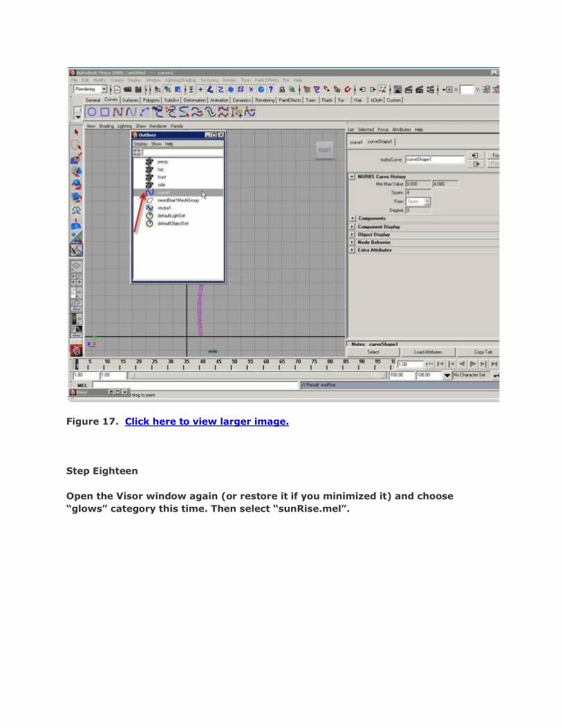
Figure 17. Click here to view larger image.
Step Eighteen
Open the Visor window again (or restore it if you minimized it) and choose
“glows” category this time. Then select “sunRise.mel”.

Figure 18. Click here to view larger image.
Step Nineteen
While curve1 is still selected, choose Paint Effects > Curve Utilities > Attach Brush
to Curves.
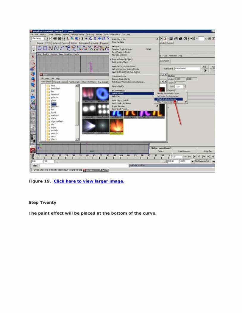
Figure 19. Click here to view larger image.
Step Twenty
The paint effect will be placed at the bottom of the curve.
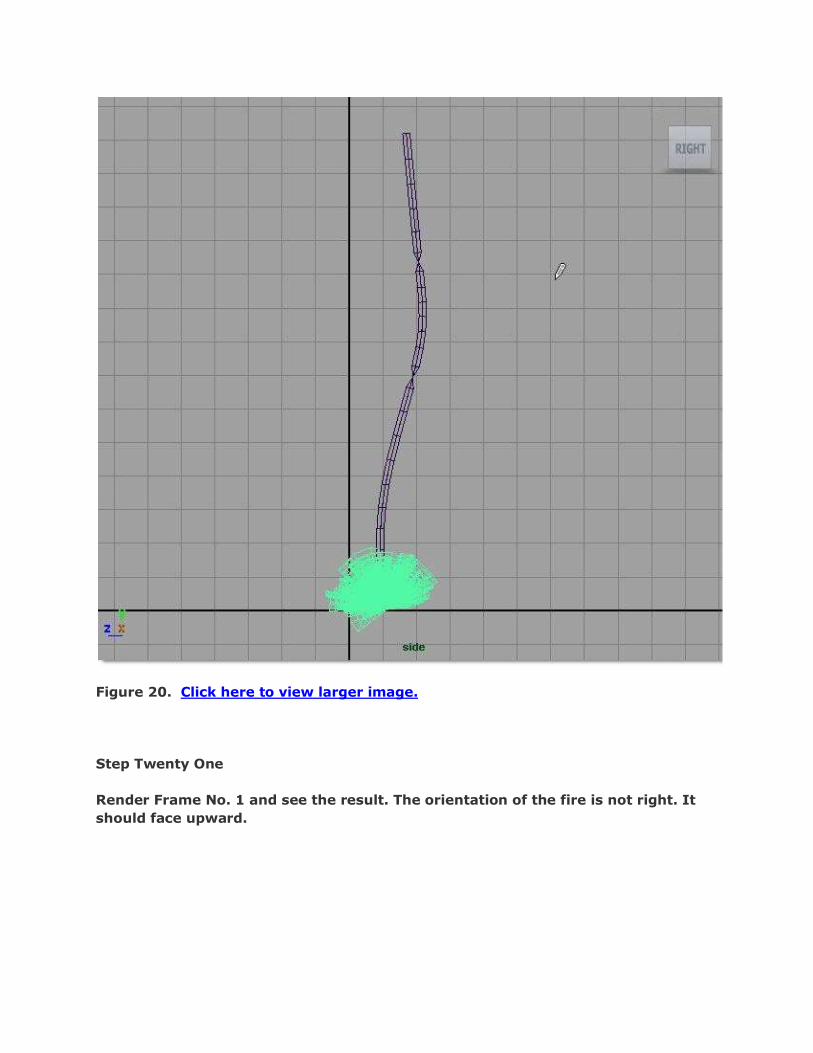
Figure 20. Click here to view larger image.
Step Twenty One
Render Frame No. 1 and see the result. The orientation of the fire is not right. It
should face upward.

Figure 21. Click here to view larger image.
Step Twenty Two
To correct this, go to attributes for sunRise1 and then expand “Tubes” group.

Figure 22. Click here to view larger image.
Step Twenty Three
Under Tubes > Creation > Width Scale, choose “Along Path” as Tube Direction.

Figure 23. Click here to view larger image.
Step Twenty Four
Choose Path Follow = -0.5 under Tubes > Forces.

Figure 24. Click here to view larger image.
Step Twenty Five
Render Frame No. 1. Now the fire direction is what we want.
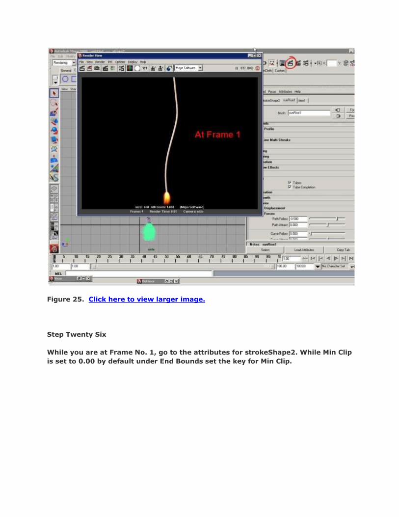
Figure 25. Click here to view larger image.
Step Twenty Six
While you are at Frame No. 1, go to the attributes for strokeShape2. While Min Clip
is set to 0.00 by default under End Bounds set the key for Min Clip.

Figure 26. Click here to view larger image.
Step Twenty Seven
Go to Frame No. 100. Set Min Clip = 1 and then set the key.
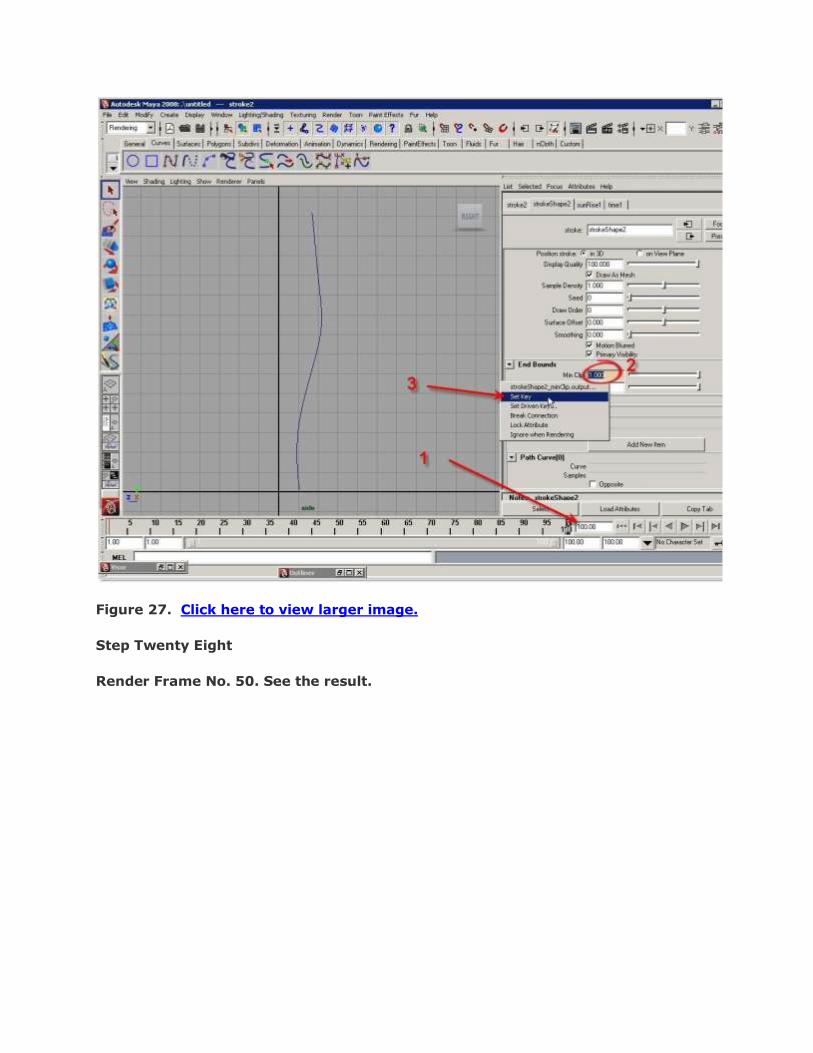
Figure 27. Click here to view larger image.
Step Twenty Eight
Render Frame No. 50. See the result.

Figure 28. Click here to view larger image.
Step Twenty Nine
Render Frame No. 99. See the result.

Figure 29. Click here to view larger image.
Step Thirty
Render Frame no. 100. Nothing is in the view. The destructive fire has eaten up
the entire rope. Hooray! Your animation is done.

Figure 30. Click here to view larger image.
Step Thirty One
Let‟s render an entire animation. Choose Window > Rendering Editor > Render
Settings.
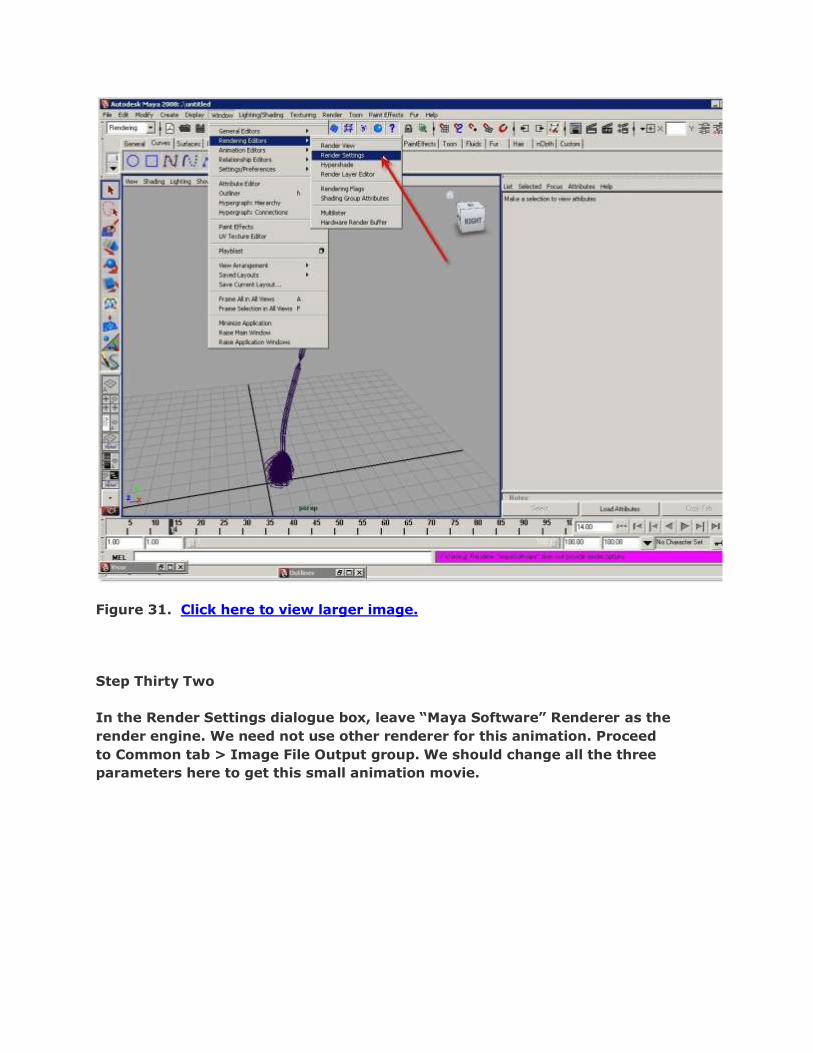
Figure 31. Click here to view larger image.
Step Thirty Two
In the Render Settings dialogue box, leave “Maya Software” Renderer as the
render engine. We need not use other renderer for this animation. Proceed
to Common tab > Image File Output group. We should change all the three
parameters here to get this small animation movie.
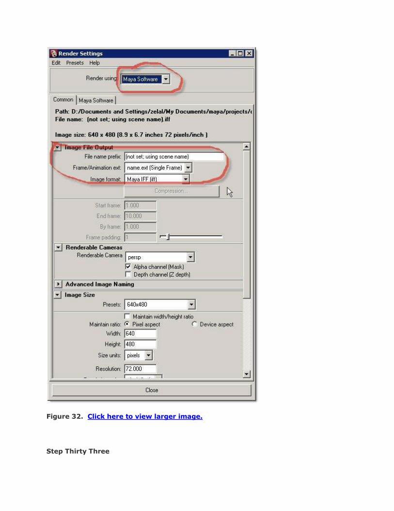
Figure 32. Click here to view larger image.
Step Thirty Three

Change the File name prefix to “Burning_Rope” and choose AVI (avi) as the Image
format. The middle parameter (Frame/Animation ext) will be automatically
changed to name.ext(Multi Frame).

Figure 33. Click here to view larger image.
Step Thirty Four
AVI (Audio Visual Interface ) is a common format for PC Screen movie. Let‟s
change it compression type i.e. Codec.
Figure 34. Click here to view larger image.
Step Thirty Five
My favorite codec is “Microsoft Windows Media Video” as it maintains the balance
between quality and file-size (at least I think it appropriate for my own PC so far).
May be, you can choose this for now.

Figure 35. Click here to view larger image.
Step Thirty Six
Just below the Compression button, set the End Frame = 100.

Figure 36. Click here to view larger image.
Step Thirty Seven
Then adjust the output size as per your requirement.
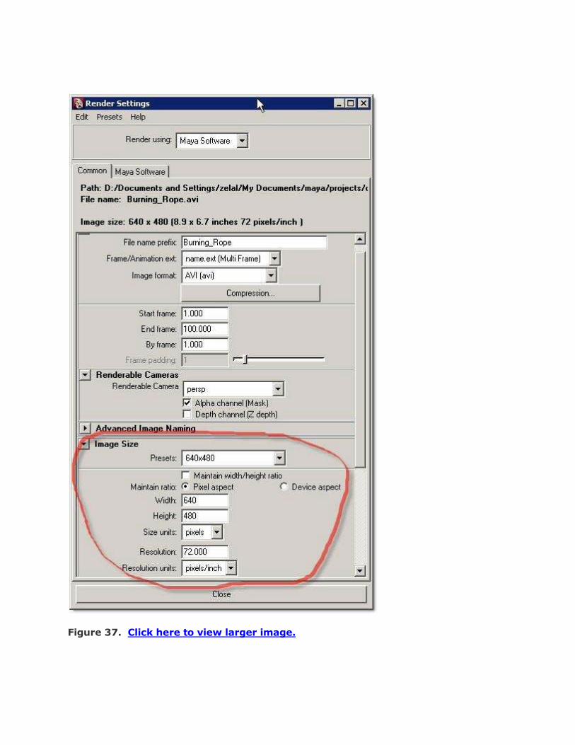
Figure 37. Click here to view larger image.

Step Thirty Eight
Now let‟s see what happens if we render the current frame after setting the
“Enable Default Light” to OFF mode (i.e. Unchecked) in the Render Options group.
Figure 38. Click here to view larger image.
Step Thirty Nine
The fire is still there. But there is no rope. We have not placed any light in the
scene. But for the rendering of some visor paint effect items such as the fiber
“wickerTubeProc1.mel” (which we used as the rope), lighting is necessary. So the
default lighting was a must for rendering this fiber paint effect.

Figure 39. Click here to view larger image.
Step Forty
Set the “Enable Default Light” back to ON and render the current frame (No.1).
This time it‟s OK.

Figure 40. Click here to view larger image.
Step Forty One
If you want to get a better quality output, go to Maya Software tab and choose
“Production Quality” from the Quality drop-down list under Anti-Aliasing group.
Close the Render Settings dialogue box.

Figure 41. Click here to view larger image.
Step Forty Two

Choose Render > Batch Render.
Figure 42. Click here to view larger image.
Step Forty Three
Maya is rendering the AVI movie. The codec I have chosen (Microsoft Windows
Media Video) need not take much time to render out the movie.
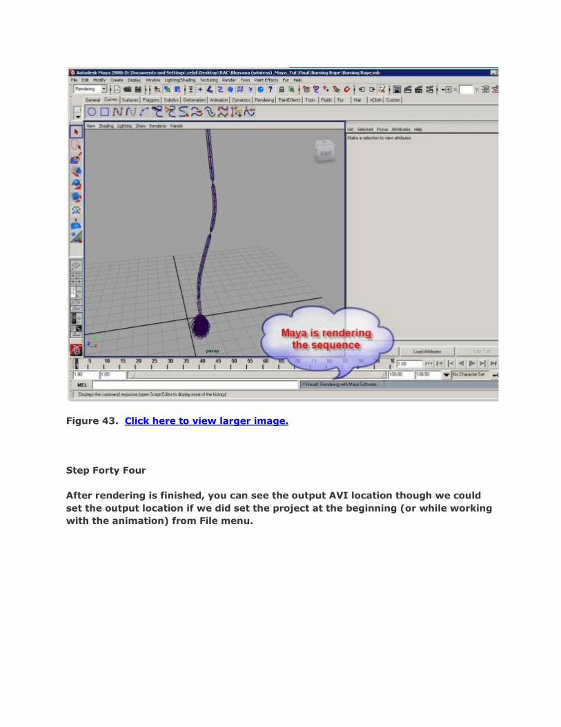
Figure 43. Click here to view larger image.
Step Forty Four
After rendering is finished, you can see the output AVI location though we could
set the output location if we did set the project at the beginning (or while working
with the animation) from File menu.

Figure 44. Click here to view larger image.
Step Forty Five
Go to the output location and play the animation. May be, we could set the
animation range to a longer period so that the animation could be more smooth.
However, this is just a practice. In your own real projects, you will render the
animation sequence in TGA/TIF or such good quality format and then import them
to a composition program (such as After Effects etc.) and get the final output from
there.
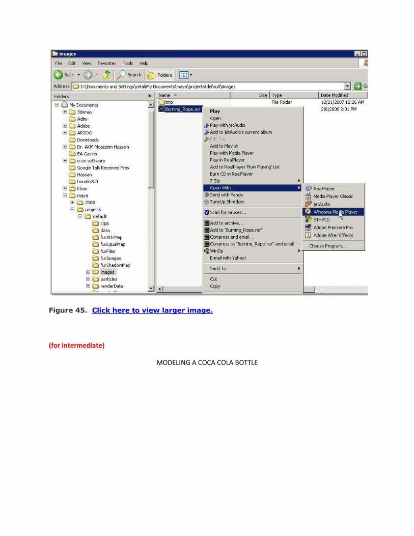
Figure 45. Click here to view larger image.
(for intermediate)
MODELING A COCA COLA BOTTLE

Introduction This tutorial is intended to show you how to make a Coca-Cola bottle using
Maya. Although, you may think making a bottle is trivial, it is easy to overlook
some of the tiny details that make your final image more desirable to look at. I will
also try to give you some tips, which can help with your workflow when you are
modeling in Maya.Alright, we start off by trying to find as many references as we
can to make our life easier during the modeling process. Here are some of the
images I found on the Internet – simply search for "Coca-Cola Bottle” in Google
and you should find tons of good references (Fig.01).
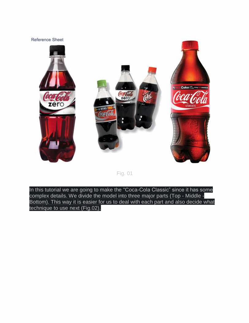
Fig. 01
In this tutorial we are going to make the "Coca-Cola Classic” since it has some complex details. We divide the model into three major parts (Top - Middle - Bottom). This way it is easier for us to deal with each part and also decide what technique to use next (Fig.02).

Fig. 02

Step 1 First we need to set up our "Image Plane” for the side view in Maya (Fig.03).
Fig. 03
Make sure that the image plane's Center X is a negative value so it won't block your model (Fig.04).
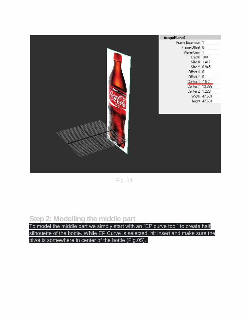
Fig. 04
Step 2: Modelling the middle part To model the middle part we simply start with an "EP curve tool” to create half
silhouette of the bottle. While EP Curve is selected, hit insert and make sure the
pivot is somewhere in center of the bottle (Fig.05).

Fig. 05
Next select Surfaces > Revolve and leave it set to the default options. Now, we have a base shape to work with (Fig.06).
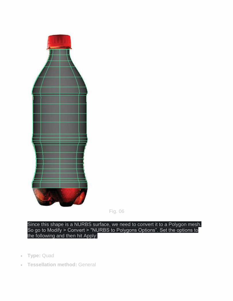
Fig. 06
Since this shape is a NURBS surface, we need to convert it to a Polygon mesh. So go to Modify > Convert > "NURBS to Polygons Options”. Set the options to the following and then hit Apply:
Type: Quad
Tessellation method: General

U type: Per span # iso params
Number U: 1
V Type: Per span # of iso params
Number V: 3
The reason we want the U, V to be set (1, 3) is because we don't want our poly shape to lose much of its detail while still as a Low Poly. If you compare the poly version to the original NURBS surface, you can clearly see that we have lost some of the curvature, but don't worry as we can apply a mesh smooth on it later (Fig.07). Also, we no longer need the NURBS surface, so simply just delete it.
Fig. 07
Now under Edit Mesh select "Insert Edge Loop Tool” and add some new edges around areas as you see in the following image. Then, use Select >Select Edge Loop Tool to select the new edges we just made and simply hit "R” and scale them towards the inside a bit. The reason we added these edges is to give more
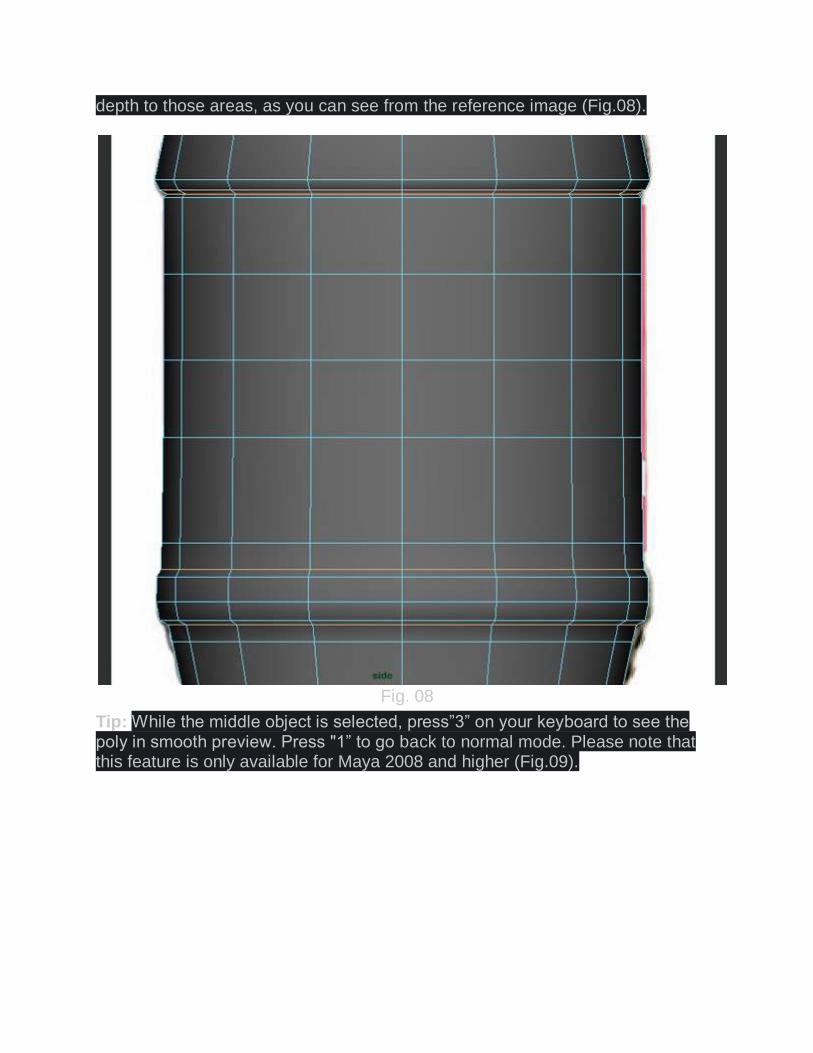
depth to those areas, as you can see from the reference image (Fig.08).
Fig. 08
Tip: While the middle object is selected, press”3” on your keyboard to see the poly in smooth preview. Press "1” to go back to normal mode. Please note that this feature is only available for Maya 2008 and higher (Fig.09).

Fig. 09
Select half of the object and delete it, then "Duplicate” the other half as an instance (Fig.10).

Fig. 10
Next, move the vertices according to following image. Try your best to match the
vertices as close as possible to the reference image (Fig.11).
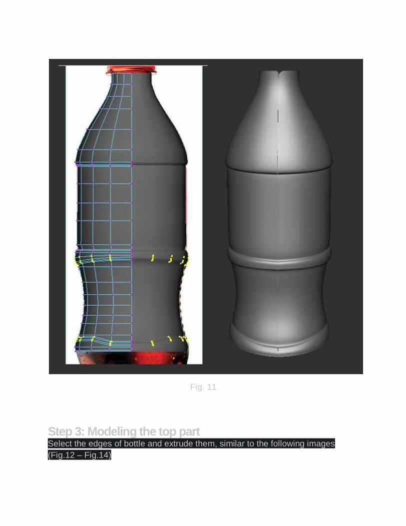
Fig. 11
Step 3: Modeling the top part Select the edges of bottle and extrude them, similar to the following images
(Fig.12 – Fig.14)
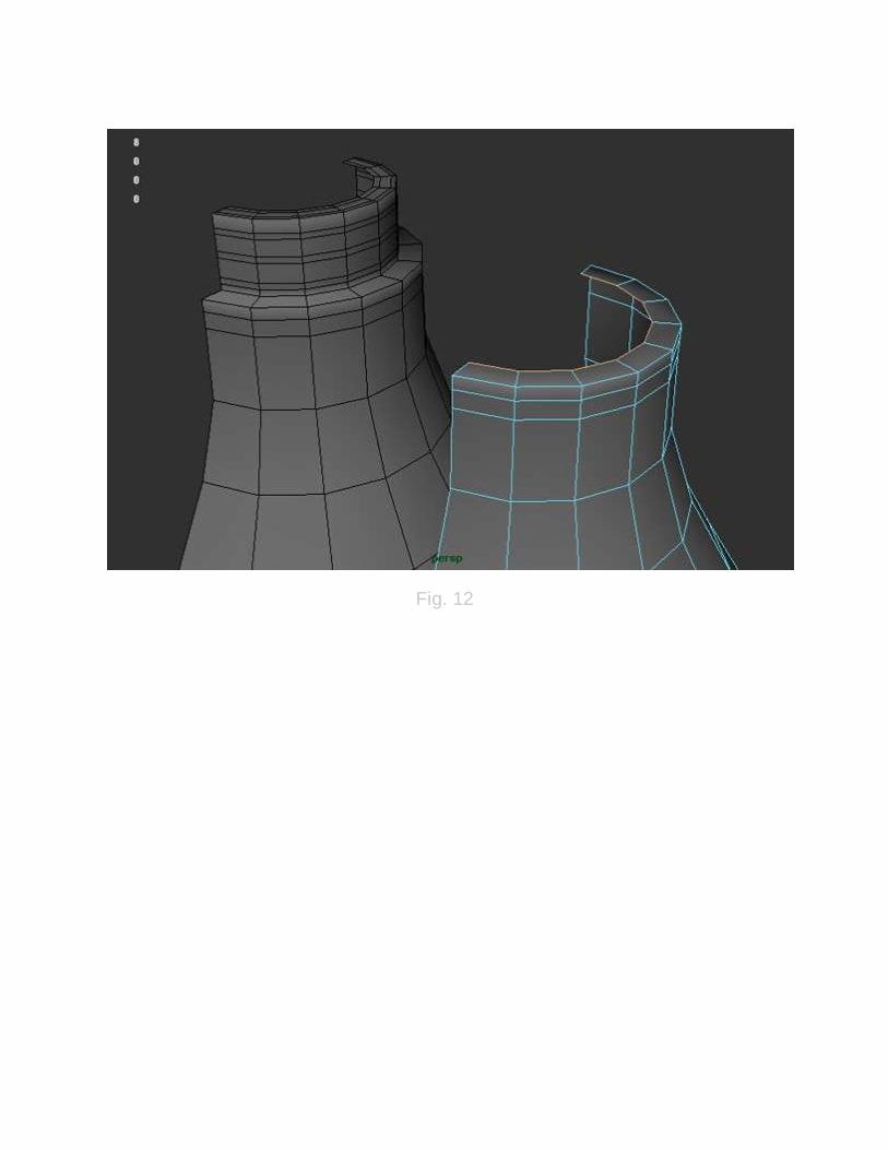
Fig. 12
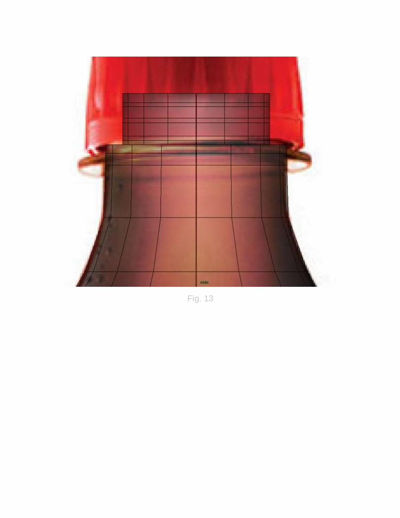
Fig. 13

Fig. 14
Modeling the Cap and Treads We start off by making a poly cylinder with the following parameters:
Radius: 2.72
Height: 2.484
Subdivision Axis: 20
Subdivision Height: 1
Subdivision Caps: 1

Select the lower vertices and scale them towards the outside a bit, then delete the lower cap. Select the lower border and extrude it towards the inside. Use the following image as a guide (Fig.15).
Fig. 15
Make a "poly Pipe” and position it under the cap. At this point, you're almost done with the cap (Fig.16).

Fig. 16
Now, make a triangular tread and align it with a cap door. You can use Vertex snap tools by holding "V” to make sure the tread is aligned properly. Make sure the pivot is exactly in the center of cap. Press "E” to switch to rotate mode then "Duplicate” it to make 20 treads (Fig.17).
Fig. 17
Step 4: Modeling the bottom part There are many different techniques that can be used to tackle the bottom part.
Here is one of them I came up with. First, make a simple "poly Sphere” and set
its parameters to the following:
Radius: 7.5321
Subdivisions Axis: 20
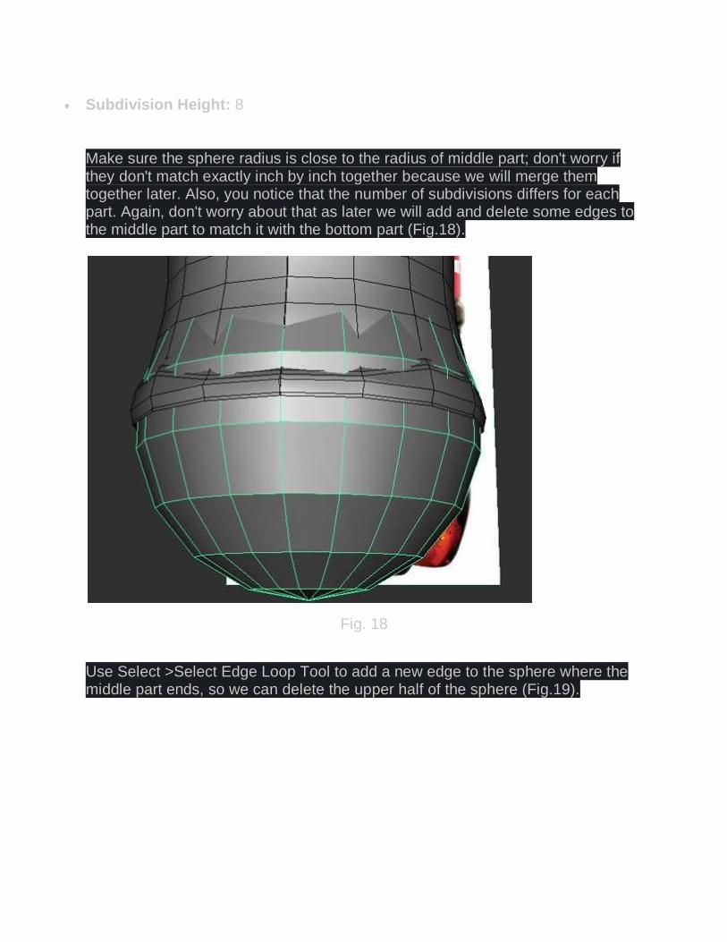
Subdivision Height: 8
Make sure the sphere radius is close to the radius of middle part; don't worry if they don't match exactly inch by inch together because we will merge them together later. Also, you notice that the number of subdivisions differs for each part. Again, don't worry about that as later we will add and delete some edges to the middle part to match it with the bottom part (Fig.18).
Fig. 18
Use Select >Select Edge Loop Tool to add a new edge to the sphere where the middle part ends, so we can delete the upper half of the sphere (Fig.19).
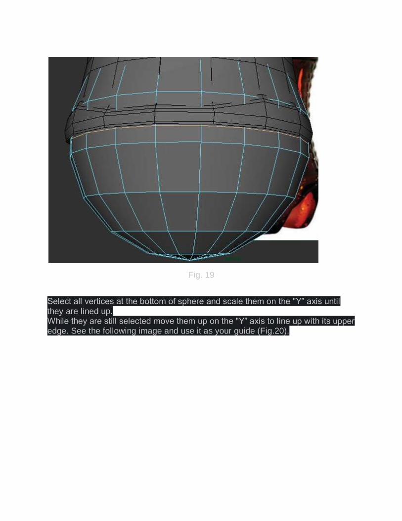
Fig. 19
Select all vertices at the bottom of sphere and scale them on the "Y” axis until they are lined up. While they are still selected move them up on the "Y” axis to line up with its upper edge. See the following image and use it as your guide (Fig.20).

Fig. 20
Here is what you should have so far. Press "3” to see the object in smooth preview (Fig.21).

Fig. 21
Next, add new edge loops at the end of the bottom part. Assign a red color material to those polys that we don't need to work with. This way, you can focus on other parts and won't get confused later when we extrude the polys between them (Fig.22).

Fig. 22
Now, try to extrude the polygons at the center to something similar to following image (Fig.23).
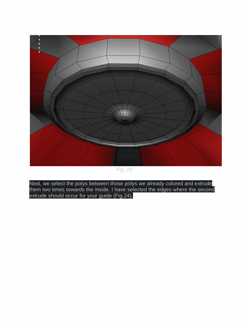
Fig. 23
Next, we select the polys between those polys we already colored and extrude them two times towards the inside. I have selected the edges where the second extrude should occur for your guide (Fig.24).
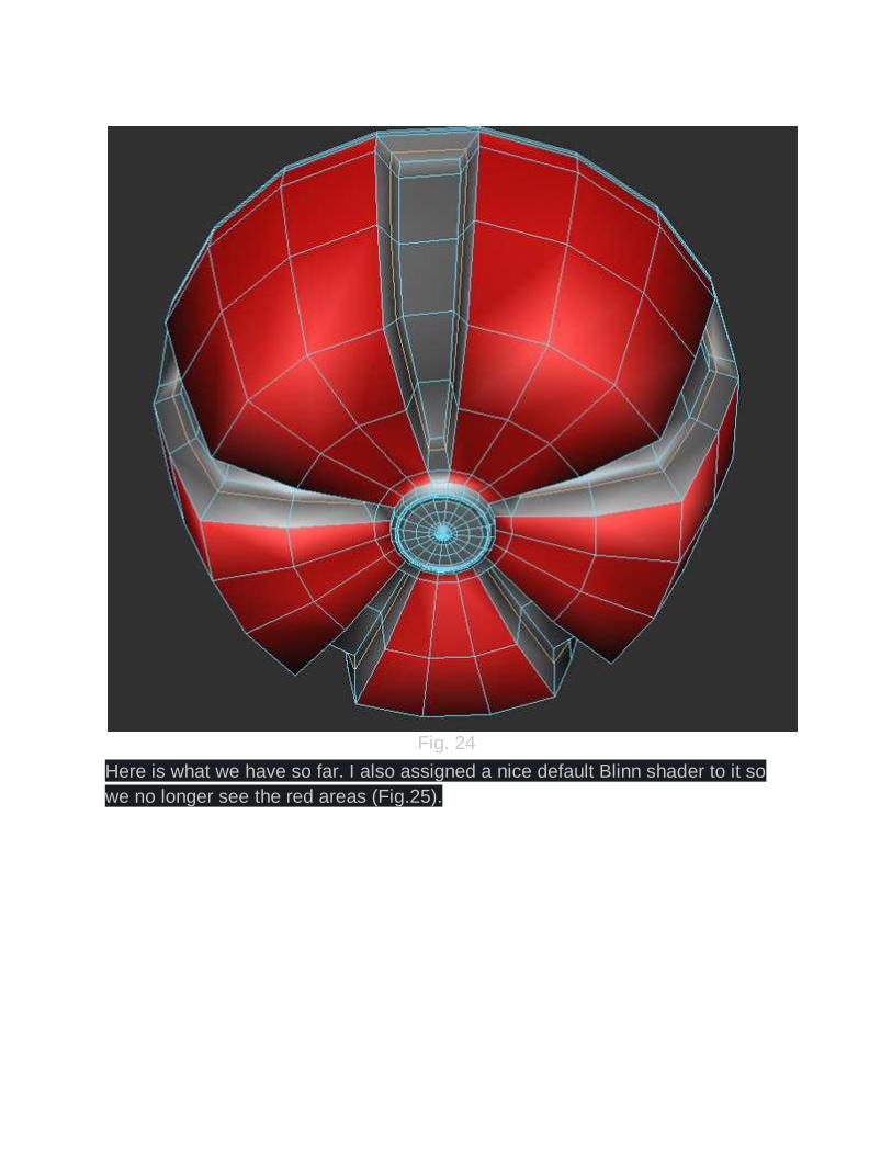
Fig. 24
Here is what we have so far. I also assigned a nice default Blinn shader to it so
we no longer see the red areas (Fig.25).

Fig. 25
Step 5: Connecting parts together First we merge the two halves of the middle part together. Simply combine and
merge them.

Now it is time to connect the middle part to the bottom and merge them together.
As we saw earlier in this tutorial, the number of subdivisions differed for both the
middle and bottom parts. To fix this problem, we add some new edge loops to
the middle part to match the edges of bottom and then we simply delete all the
old edges that don't match (Fig.26 & Fig.27).
Fig. 26

Fig. 27
Once you are done, merge all the vertices together and extrude the middle towards the inside where the middle and bottom part are connected. Call the new object "Bottle” (Fig.28).
Fig. 28
Step 6: Adding extra details to middle part In this step, we are going to add more definition to the middle part. Simply, move
the vertices and extrude their faces to make a basic slot. In this model we need
to have four slots (Fig.29).
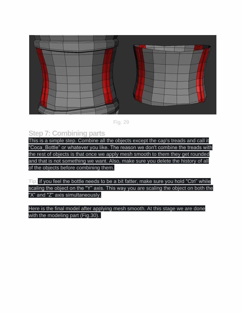
Fig. 29
Step 7: Combining parts This is a simple step. Combine all the objects except the cap's treads and call it
"Coca_Bottle” or whatever you like. The reason we don't combine the treads with
the rest of objects is that once we apply mesh smooth to them they get rounded
and that is not something we want. Also, make sure you delete the history of all
of the objects before combining them.
Tip: if you feel the bottle needs to be a bit fatter, make sure you hold "Ctrl” while
scaling the object on the "Y” axis. This way you are scaling the object on both the
"X” and "Z” axis simultaneously.
Here is the final model after applying mesh smooth. At this stage we are done
with the modeling part (Fig.30).
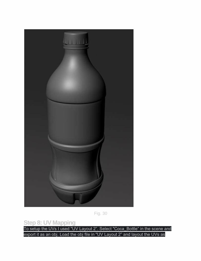
Fig. 30
Step 8: UV Mapping To setup the UVs I used "UV Layout 2”. Select "Coca_Bottle” in the scene and
export it as an obj. Load the obj file in "UV Layout 2” and layout the UVs as
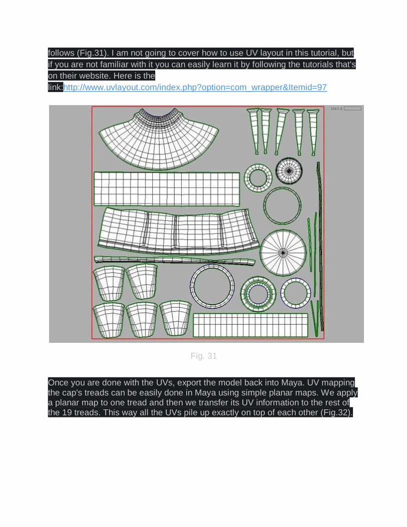
follows (Fig.31). I am not going to cover how to use UV layout in this tutorial, but
if you are not familiar with it you can easily learn it by following the tutorials that's
on their website. Here is the
link:http://www.uvlayout.com/index.php?option=com_wrapper&Itemid=97
Fig. 31
Once you are done with the UVs, export the model back into Maya. UV mapping the cap's treads can be easily done in Maya using simple planar maps. We apply a planar map to one tread and then we transfer its UV information to the rest of the 19 treads. This way all the UVs pile up exactly on top of each other (Fig.32).
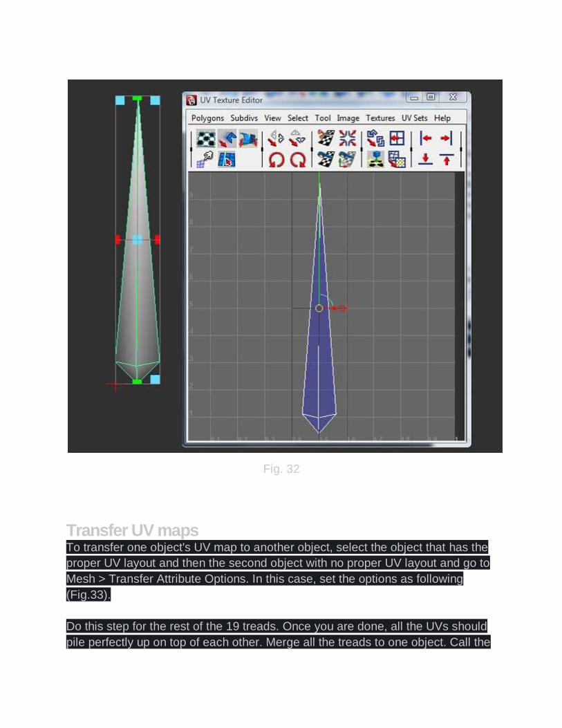
Fig. 32
Transfer UV maps To transfer one object's UV map to another object, select the object that has the
proper UV layout and then the second object with no proper UV layout and go to
Mesh > Transfer Attribute Options. In this case, set the options as following
(Fig.33).
Do this step for the rest of the 19 treads. Once you are done, all the UVs should
pile perfectly up on top of each other. Merge all the treads to one object. Call the

new object "Cap's Tread”
Fig. 33
Step 9: Exporting "Coca_Bottle” UV to Photoshop for bump mapping Select "Coca_Bottle”, and then go to the UV Texture Editor. Once UTE pops up,
go to Polygons > UV Snapshot. Set its options to those shown in Fig.34.
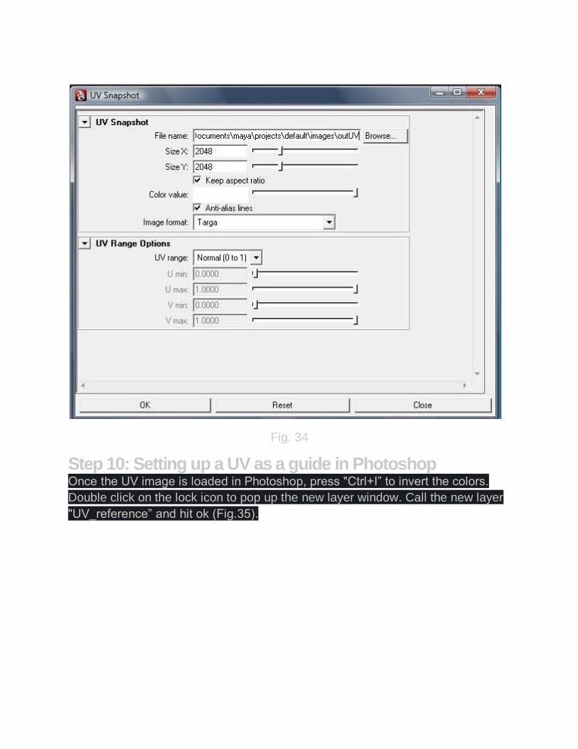
Fig. 34
Step 10: Setting up a UV as a guide in Photoshop Once the UV image is loaded in Photoshop, press "Ctrl+I” to invert the colors.
Double click on the lock icon to pop up the new layer window. Call the new layer
"UV_reference” and hit ok (Fig.35).
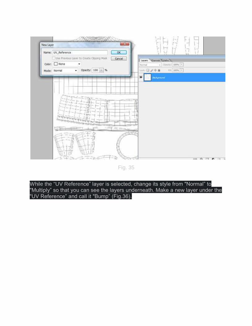
Fig. 35
While the "UV Reference” layer is selected, change its style from "Normal” to "Multiply” so that you can see the layers underneath. Make a new layer under the "UV Reference” and call it "Bump” (Fig.36).

Fig. 36
Now, we need to gather some images together to draw the Coca-Cola logo, and
small dots on our bottle. To make the small dots under the logo, I used the
following texture (Fig.37).

Fig. 37
The rest of the small dots can be simply made by using the "Ellipse Tool” in Photoshop and duplicating them using "Alt+Drag” (Fig.38).
Fig. 38
Here is a Coca-Cola logo that I found on Google, which is a nice high resolution image with transparency. Simply, convert the color to white with a black background (Fig.39 & Fig.40).

Fig. 39
Fig. 40
Now that we have all the images we need, you can start aligning them on the UV we exported from Maya. Here is what I came up with (Fig.41).

Fig. 41
Save the final image in tga format and name it "CocaCola_Bump.tga”.
Step 11: Setup bump map in Maya Simply make a blinn shader and apply our texture ("CocaCola_Bump.tga”) to its
Bump mapping section. Try to reduce the "Bump depth” to something around

0.040. Also, make sure reflection is set to zero (Fig.42 – Fig.44).
Fig. 42

Fig. 43

Fig. 44
Apply the Blinn shader to our Coca-Cola bottle. Make sure "Smooth shade all”, "Textured”, "High quality” are all checked, so we can see what our bump map looks like in the viewport. You should get something similar to this (Fig.45).

Fig. 45
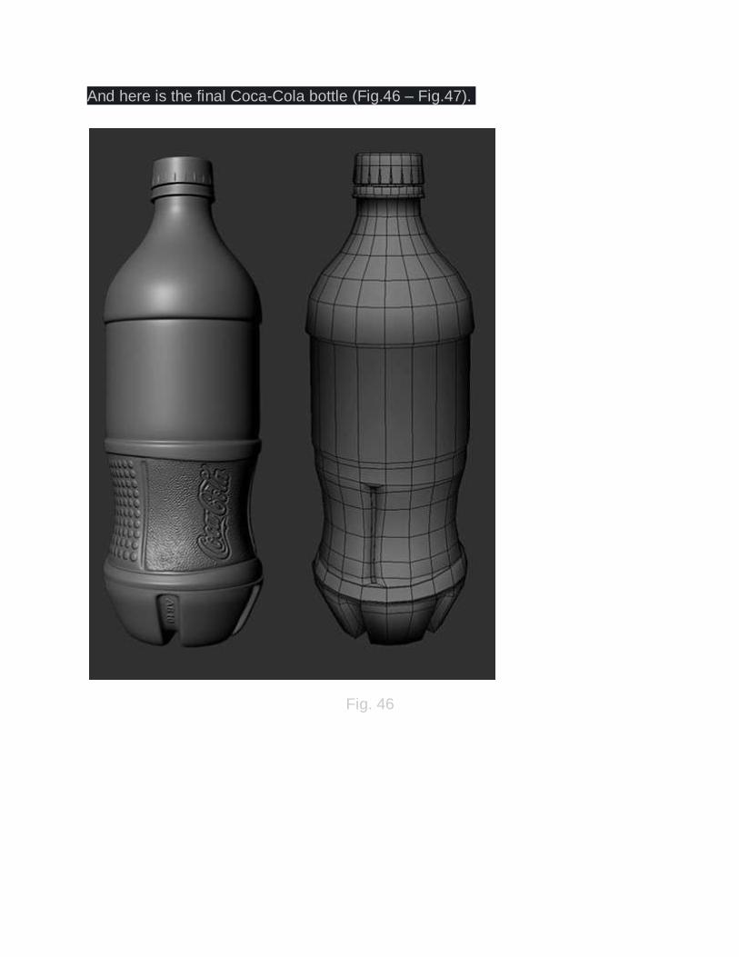
And here is the final Coca-Cola bottle (Fig.46 – Fig.47).
Fig. 46

Fig. 47
Conclusion I hope you have enjoyed this tutorial and the information in it was useful for you. Also keep in mind that the technique that I describe here can be applied in a similar way to any 3D packages out there. Please feel free to email me at in case you have any questions or problems regarding this tutorial.