3d mobility learning and regression of articulated
TRANSCRIPT
Workshop on Virtual Reality Interaction and Physical Simulation VRIPHYS (2012)J. Bender, A. Kuijper, D. W. Fellner, and É. Guérin (Editors)
3D Mobility Learning and Regression of Articulated, TrackedRobotic Vehicles by Physics-based Optimization
Panagiotis Papadakis and Fiora Pirri
ALCOR - Vision, Perception and Cognitive Robotics LaboratoryDepartment of Control and Management Engineering, University of Rome ’La Sapienza’, Italy
AbstractMotion planning for robots operating on 3D rough terrain requires the synergy of various robotic capabilities,from sensing and perception to simulation, planning and prediction. In this paper, we focus on the higher level ofthis pipeline where by means of physics-based simulation and geometric processing we extract the information thatis semantically required for an articulated, tracked robot to optimally traverse 3D terrain. We propose a modelthat quantifies 3D traversability by accounting for intrinsic robot characteristics and articulating capabilitiestogether with terrain characteristics. By building upon a set of generic cost criteria for a given robot state and 3Dterrain patch, we augment the traversability cost estimation by: (i) unifying pose stabilization with traversabilitycost estimation, (ii) introducing new parameters into the problem that have been previously overlooked and (iii)adapting geometric computations to account for the complete 3D robot body and terrain surface. We apply theproposed model on a state-of-the-art Search and Rescue robot by performing a plurality of tests under varyingconditions and demonstrate its efficiency and applicability in real-time.
Categories and Subject Descriptors (according to ACM CCS): I.3.5 [Computer Graphics]: Physically basedmodeling—Cognitive science
1. INTRODUCTION
Parallel to common robotic applications where robots oper-ate within structured environments, there has been an evi-dent interest in advancing robot technology so that they canbe deployed into outdoor, off-road, natural, as well as un-natural environments. Robotic applications such as planetaryexploration, Urban Search and Rescue (USAR), forestry andmining are made feasible by designing robots with reconfig-urable components that adapt to rough terrain. Towards thisgoal, typically, there exist a number of issues that need to beaddressed, namely; (i) estimation of the terrain traversabil-ity, (ii) path planning and (iii) adapting the configuration ofthe robot for the purpose of motion planning.
The focus of this paper relies primarily in alleviating thefirst and third issue through a unified perspective. Our moti-vation originates from the fact that while there is extensivework in relation to a number of applications, there is a fairlylimited amount of work in the domain of USAR environ-ments that are undoubtedly the most complex in terms of ter-rain irregularities and span the highest range in the diversity
of terrain classes [KPG∗12]. Furthermore, due to the com-plexity and plurality of challenges that are involved, mostresearch efforts have been dedicated to address these issuesdistinctively and often by imposing several oversimplifica-tions.
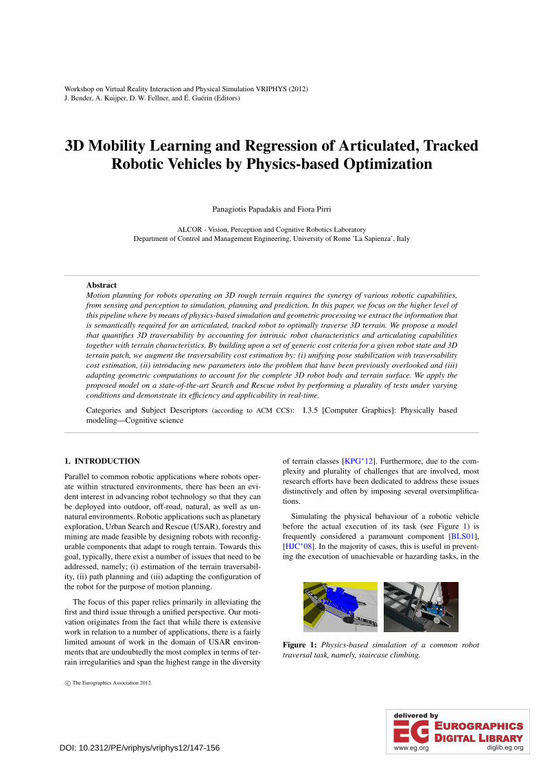
Simulating the physical behaviour of a robotic vehiclebefore the actual execution of its task (see Figure 1) isfrequently considered a paramount component [BLS01],[HJC∗08]. In the majority of cases, this is useful in prevent-ing the execution of unachievable or hazarding tasks, in the
Figure 1: Physics-based simulation of a common robottraversal task, namely, staircase climbing.
c© The Eurographics Association 2012.
DOI: 10.2312/PE/vriphys/vriphys12/147-156
P. Papadakis et al. / 3D Mobility Learning and Regression of Articulated, Tracked Robotic Vehicles by Physics-based Optimization
sense that if a simulated task eventually results in a failure,then this would also be the expected outcome in the real set-ting. When the robot and its interaction with the environ-ment can be simulated at sufficiently high fidelity, then thesimulated plan can also be used in order to guide the actualrobotic vehicle [HK07] or in the context of shared-autonomyoperation modes [ONY∗11], [CB08].
In this paper, we propose a methodology to consistentlyand precisely assess static traversability costs for reconfig-urable tracked mobile robots operating in 3D terrain and inparticular, for USAR environments. We consider both intrin-sic robot characteristics and articulating capabilities in com-bination to the entire terrain surface and model the physi-cal behaviour of a given robot and its interaction inside agiven environment, by considering the exact 3D shape of therobot and the terrain surface. The result yields the stable poseof the robot together with a set of corresponding cost mea-surements, that quantify the difficulty of the robotic vehicleto reside over the given terrain. The general framework forlearning and regressing the mobility of a robotic vehicle in3D terrain through a physics-based simulation was sketchedpartly in our earlier work [GPPP11]. In the present work weunfold the details behind the theory and implementation ofthe complete framework, whose contributions are summa-rized as follows:
– A simulated, physics-based approach to efficiently obtainthe stable state of an articulated robot on a given 3D ter-rain, that accounts for a terrain model, robot model as wellas its stability and kinematic constraints.
– A framework for quantifying static, 3D terrain traversabil-ity of the robot at the optimally stable state.
As a direct application of the above two contributions, wecan endow the robot with the ability to acquire its mobilityskills through off-line learning within an exhaustive rangeof 3D terrain shapes. In turn, the robot is rendered capableof regressing the traversability of an encountered terrain inreal-time and suitably adjust its morphology upon traversal.
We organize the remainder of the paper as follows: InSection 2 we review the related work in 3D terrain mobil-ity analysis and in Section 3, we first formulate the problemthat we are addressing and continue by describing the pro-posed methodology. In Section 4 we present our experimentsusing the proposed approach and in Section 5 we summarizethe contributions of this paper.
2. RELATED WORK
The predominant approach for measuring the traversabil-ity of 3D terrain concerns the analysis of 2D Digital Ele-vation Maps (DEM) [KK92], originating from OccupancyGrid maps whose usage in robotics is accredited to Moravec[ME85]. The majority of methods for quantifying terraintraversability of mobile robots, concerns the computation ofa set of features that are based on a simplistic terrain model
and simulating the robot as a point or a basic geometric en-tity, such as a rectangle or a sphere.
Within this line of thought, one of the earliest approachescorresponds to the work Langer et al. [LRH94] who com-puted elevation statistics from the set of 3D points withineach grid cell, namely, the maximum, minimum and vari-ance of height and slope that were checked by hard thresh-olds set according to the UGV (Unmanned Ground Vehicle)capabilities. In the pioneering work of Genery [Gen99], acost function aggregates the elevation, slope, roughness anddata point accuracy. Those features were computed by iter-ative plane-fitting that adaptively weighed the fitted pointsaccording to their accuracy, roughness and distance from thecell center. The work of Helmick et al. [HAM09] goes astep further by using several description levels of increas-ing granularity. They build upon fine terrain descriptions ex-tracted from the GESTALT system [GMM02] that outputs agoodness map which quantifies traversability by locally fit-ting planar patches and using the patch statistics to derivestep, roughness, pitch and border hazards. In a higher-level,terrain is classified into traversability classes by threshold-ing the goodness value of each cell. On the other hand, thefocus of the work of Singh et al. [SSS∗00] was primarily inalleviating uncertainty and error, by assessing traversabilityjointly through quantifying terrain goodness and certainty.Goodness is determined as the minimum of the roll, pitchand roughness of planar rover-sized patches that are com-puted by fitting planes onto the stereo range points and com-puting the residual of the planes while certainty depends onthe number and variance of points within the patch as wellas its distance from the position of the UGV.
Notable, earlier approaches that build higher-level roboticrepresentations and take into account robot-dependent vari-ables are comparatively limited. A representative examplecorresponds to the work of Bonnafous et al. [BLS01] whomodel traversability as a danger attribute, taking into ac-count the robot configuration and stability constraints relatedto the pitch/roll angles of the articulated components and anuncertainty constraint that accounts for the sparseness of in-formation within the DEM. In [VDH06], one type of mapstores a cost incurred by the presence of vegetation encodingthe confidence of terrain reconstruction that could be used toplan paths below canopy and a second type of map is derivedby superposition of the robot across different directions onthe DEM and estimating its roll, pitch and ground clearance.These estimates are then smoothly mapped into a finite fixedinterval and the total cost is taken as the least favourable ofthe three criteria. In [HJC∗08], the traversability of unknownterrain is determined by employing forward simulation of apath following within the ROAMS environment and calcu-lating the energy consumption along a path together with theamount of wheel slippage. In the recent work of Ishigamiet al. [INY11] terrain traversability is evaluated through thedynamic mobility index that considers robot stability, wheelslippage, time duration and energy consumption. Terrain
c© The Eurographics Association 2012.
148
P. Papadakis et al. / 3D Mobility Learning and Regression of Articulated, Tracked Robotic Vehicles by Physics-based Optimization
Figure 2: Stable state and cost assessment pipeline.
roughness is computed as the standard deviation of eleva-tion across the robot footprint when projected onto the mapat varying yaw angle and wheel slippage is quantified bymeasuring the terrain roll/pitch inclination. While these ap-proaches assess robot mobility at a finer level, there existsno previous work to the best of our knowledge, for activelyadaptable, tracked, mobile robots operating in USAR envi-ronments that can reliably model the robot and its interactionwith the terrain, further taking into account its kinematic andstability constraints. Earlier work that bears the highest sim-ilarity in terms of scenario and robotic vehicle concerns thework of Okada et al. [ONY∗11]. In contrast to our approach,their stable pose estimation is based on regressing the slopeof the terrain and not by considering its interaction with theUGV while the stability cost does not take into account thecomplete geometry of the interacting surfaces. Finally, theirgoal was to develop a shared, human-robot mode of motionwhile our goal is to allow the robot to learn its mobility skillsand allow it to optimize its motion planning autonomously.
3. PROPOSED METHODOLOGY
The problem that we address can be described as follows. Weseek to obtain the stable pose of a UGV on top a given terrainconsidering its mobility capabilities, together with its phys-ical interaction with the terrain involving the effects of sur-face collisions, gravitational force and potential slipping. Wefurther aim to quantify the capability of the vehicle to reside,statically, over a terrain under a specific state, by taking intoaccount its kinematic constraints together with a set of crite-ria based on which the optimality of a state can be assessed.The pipeline for obtaining the stable robot state and the cor-responding traversability costs is decomposed into three se-quential stages as shown in Figure 2.
More formally, we denote the configuration space of arobot as C = (x,y,z,φ ,θ ,ψ,α1,α2, ...,αn) ⊂ Rn+6, where(x,y,z) denotes its 3D position, (φ ,θ ,ψ) its roll, pitch, yaw
and (α1,α2, ...,αn) give the rotations of the n articulatingcomponents of the robot. The state space S is derived fromthe kinematic constraints of the particular robot. A sub-configuration space Cm describes a subspace of C, througha mapping m : C 7→ Cm ∈ Rd , d < n+6 yielding the corre-sponding sub-state space Sm.
We represent a terrain surface as a DEM and denoted byM : M(i, j)→ R where i ∈ 1,2, ..,w, j ∈ 1,2, .., l, andw, l correspond to the width and length of the grid respec-tively. The value of M(i, j) is used to capture the height of thesupporting terrain at the cell (i, j) according to the global co-ordinate frame. A DEM is the equivalent of a 2D depth mapin the computer graphics domain. Although any 3D surfacecould be used, we base our description using DEM as theyfacilitate path planning by using graph-search algorithms.
In general, we could be interested in determining all thepossible states of the robot for a cell (i, j) and further or-der the different cases according to the cost. Most often,however, motion planners do not search exhaustively withina cost map, rather, the search space is constrained througha set of precomputed paths that consider the maneuver-ing capabilities of the vehicle (e.g. as in [LF09], [HK07]and [HGFK08]). Under this perspective, e.g. when usingan arc-based path planner, the search space is constrainedby eliminating a number of degrees of freedom from theinitial C space. In particular, we obtain the sub-state spaceSpath = (x,y,ψ) through the set of fixed candidate paths infront of the robot generated by the path planner that pre-scribe the position and direction that the robot would follow.Hence, the traversability assessment problem as sketched inFigure 2, decomposes into the following steps:
– Estimation of the sub-state ster = (z,φ ,θ) as a result ofthe contact of the robot with the terrain (Section 3.1).
– Estimation of the sub-state sart = (α1,α2, ...,αn) corre-sponding to the rotation angles of the articulated compo-nents, as a result of the robot kinematic constraints andcontact with the terrain (Section 3.2).
– Traversability costs assessment (Section 3.3).
For the complete framework to be applicable, the follow-ing main assumptions are primarily accommodated:
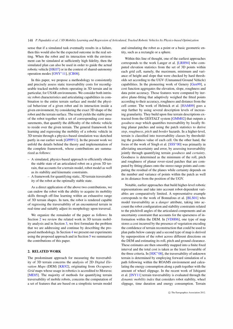
i. The robot acquires a 3D point cloud of the terrain in ques-tion, that is subsequently transformed into a correspond-ing polygonal surface (as shown in Figure 3).
Figure 3: 3D point clouds as acquired from the UGV and reconstructed surfaces of two churches damaged by earthquake.
c© The Eurographics Association 2012.
149
P. Papadakis et al. / 3D Mobility Learning and Regression of Articulated, Tracked Robotic Vehicles by Physics-based Optimization
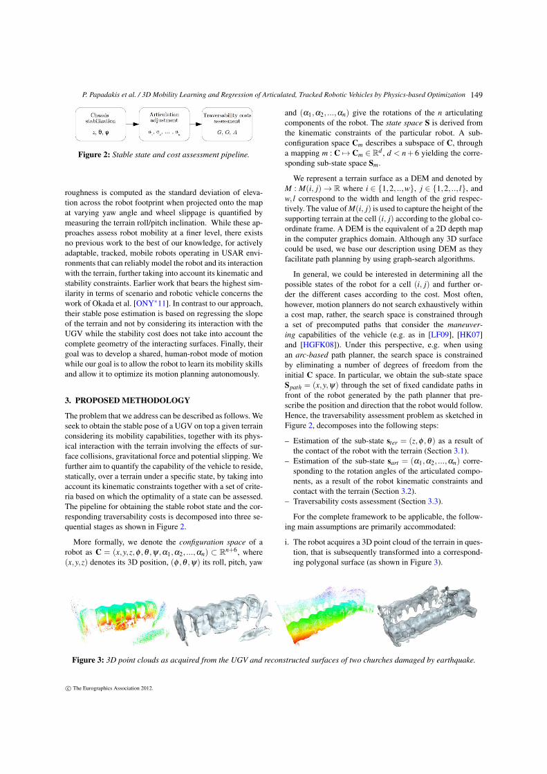
Figure 4: Top row: Snapshots of the stable sub-state estimation process of robot elevation and orientation ster. From left toright, the robot is shown at its initial given state spath, intermediate state and its final stable state. Bottom row: Snapshots ofthe sub-state estimation of rotation angles of articulating bodies sart . From left to right, the robot is shown at its stable chassisstate, intermediate reconfiguration state and at its final optimal state.
ii. The polygonal surface is not subject to changes and canbe considered as sufficiently rigid to support the weightof the robotic vehicle.
Since our focus is not to develop new methodologies toaccommodate these conditions, for our scenarios we foundparticularly useful the application of optimized kernel-basedsurface density estimation. In particular, through the use ofSupport Vector Machines (SVM) [PP11, TD99, SGS05], weobtain the oriented polygonal surface (see Figure 3) as the0-level set of the hyper-decision surface. Our motivation inusing this approach is mainly due to the formulation that al-lows dealing with noise and error by regulating the slack ra-tio and with uncertainty through the variance of the Gaussiankernel.
3.1. Sub-state estimation of robot elevation andorientation
The estimation of the sub-state ster = (z,φ ,θ) is performedthrough a mapping of the state spath = (x,y,ψ), namely,ster = gR(spath). Here, gR is the mapping from the path sub-state space Spath to the terrain sub-state space Ster, that mod-els the physical interaction of the main body of the robotunder consideration when residing over the terrain at a statespath, taking into account gravity, friction, bounciness andsoftness of the terrain.
The exact estimation of the latter three parameters re-quires appearance-based terrain classification or the use of
dedicated sensors. Depending on the available robot percep-tion capabilities, these parameters could be incorporated intothe physics-based simulation at the cost of increased com-putational complexity. Typically, however, robot movementswithin USAR scenarios are of low speed and on rough ter-rains that implies setting the Coulomb friction coefficientsto comparatively high values, while bounciness and soft-ness are trivial. In this context, the only information requiredby our model is the 3D shape of the vehicle (and that ofthe terrain), the robot’s mass characteristics and its inertiaaxes, which are acquired directly from the robot specifica-tions [Blu11].
To estimate ster, we overlay the robot on top of the terrainat the given sub-state spath and iterate in time until its motion(linear and angular) vanishes. At that moment, we considerthe robot as stably residing over the terrain. This step can becomprehended as a simulated parallelism of the natural sta-bilization process that would take place if the robotic vehiclelaid on the given terrain region.
At the top row of Figure 4, we show snapshots of thethree distinct stages of the physically-based simulation ofthis step, namely, initial, intermediate and stable state andin Algorithm 1 we describe the respective steps. Note thatthe final stable state may have caused a drift from the initialspath = (x,y,ψ), as a result of the robot stabilization pro-cess. In Section 3.3 we explain how we explicitly take thisinto account into the traversability cost assessment.
c© The Eurographics Association 2012.
150
P. Papadakis et al. / 3D Mobility Learning and Regression of Articulated, Tracked Robotic Vehicles by Physics-based Optimization
Algorithm 1: Sub-state computation of the UGV eleva-tion and orientation
Input: M: DEM of the terrainugv: 3D kinematic model of the vehiclespath = (x,y,ψ): Initial position and yaw of the ugv within MOutput: ster = (z,φ ,θ)begin
Chassis_Stable = f alset = 0while Chassis_Stable = f alse do
Compute (ugv,M, t) interactionif (v = p(x,y,z)' 0 ∧ ω = r(φ ,θ ,ψ)' 0) then
Chassis_Stable = truet = t +∆t
end
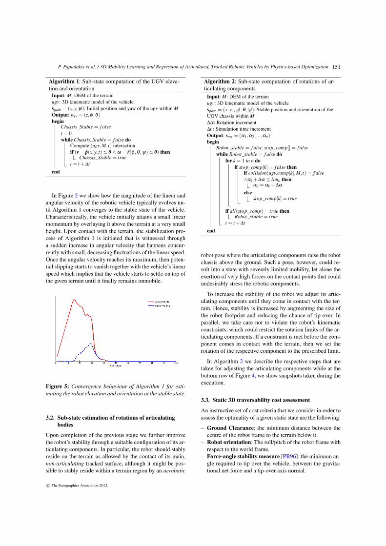
In Figure 5 we show how the magnitude of the linear andangular velocity of the robotic vehicle typically evolves un-til Algorithm 1 converges to the stable state of the vehicle.Characteristically, the vehicle initially attains a small linearmomentum by overlaying it above the terrain at a very smallheight. Upon contact with the terrain, the stabilization pro-cess of Algorithm 1 is initiated that is witnessed througha sudden increase in angular velocity that happens concur-rently with small, decreasing fluctuations of the linear speed.Once the angular velocity reaches its maximum, then poten-tial slipping starts to vanish together with the vehicle’s linearspeed which implies that the vehicle starts to settle on top ofthe given terrain until it finally remains immobile.
Figure 5: Convergence behaviour of Algorithm 1 for esti-mating the robot elevation and orientation at the stable state.
3.2. Sub-state estimation of rotations of articulatingbodies
Upon completion of the previous stage we further improvethe robot’s stability through a suitable configuration of its ar-ticulating components. In particular, the robot should stablyreside on the terrain as allowed by the contact of its main,non-articulating tracked surface, although it might be pos-sible to stably reside within a terrain region by an acrobatic
Algorithm 2: Sub-state computation of rotations of ar-ticulating components
Input: M: DEM of the terrainugv: 3D kinematic model of the vehiclespose = (x,y,z,φ ,θ ,ψ): Stable position and orientation of theUGV chassis within M∆α: Rotation increment∆t : Simulation time incrementOutput: sart = (α1,α2, ...,αn)begin
Robot_stable = f alse,stop_comp[] = f alsewhile Robot_stable = f alse do
for k = 1 to n doif stop_comp[k] = f alse then
if collision(ugv.comp[k],M, t) = f alse∧αk +∆α ≤ limk then
αk = αk +∆α
elsestop_comp[k] = true
if all(stop_comp) = true thenRobot_stable = true
t = t +∆t
end
robot pose where the articulating components raise the robotchassis above the ground. Such a pose, however, could re-sult into a state with severely limited mobility, let alone theexertion of very high forces on the contact points that couldundesirably stress the robotic components.
To increase the stability of the robot we adjust its artic-ulating components until they come in contact with the ter-rain. Hence, stability is increased by augmenting the size ofthe robot footprint and reducing the chance of tip-over. Inparallel, we take care not to violate the robot’s kinematicconstraints, which could restrict the rotation limits of the ar-ticulating components. If a constraint is met before the com-ponent comes in contact with the terrain, then we set therotation of the respective component to the prescribed limit.
In Algorithm 2 we describe the respective steps that aretaken for adjusting the articulating components while at thebottom row of Figure 4, we show snapshots taken during theexecution.
3.3. Static 3D traversability cost assessment
An instructive set of cost criteria that we consider in order toassess the optimality of a given static state are the following:
– Ground Clearance; the minimum distance between thecentre of the robot frame to the terrain below it.
– Robot orientation; The roll/pitch of the robot frame withrespect to the world frame.
– Force-angle stability measure [PR96]; the minimum an-gle required to tip over the vehicle, between the gravita-tional net force and a tip-over axis normal.
c© The Eurographics Association 2012.
151
P. Papadakis et al. / 3D Mobility Learning and Regression of Articulated, Tracked Robotic Vehicles by Physics-based Optimization
While other criteria could be considered as well (e.g. theZero Moment Point (ZMP) distance [VB04], traction effi-ciency or terrain features), the basis of the proposed modelfor traversability assessment is the usage of the minimal andmost common set of perceptual capabilities, where the robothas knowledge of the 3D terrain surface that it resides on aswell as its relative pose. In this perspective, we generalizethe applicability of the proposed framework by consideringonly criteria that involve distances and geometric process-ing that can be assumed as readily applicable given the 3Dmodel of the UGV and that of the terrain surface.
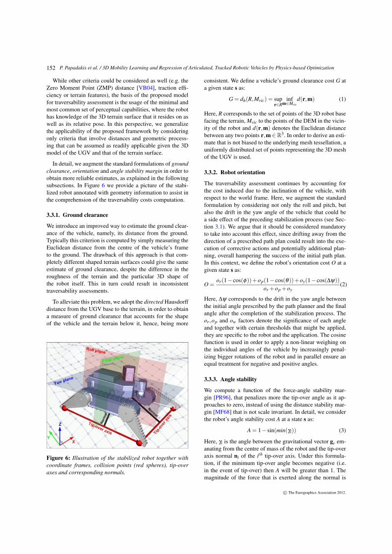
In detail, we augment the standard formulations of groundclearance, orientation and angle stability margin in order toobtain more reliable estimates, as explained in the followingsubsections. In Figure 6 we provide a picture of the stabi-lized robot annotated with geometry information to assist inthe comprehension of the traversability costs computation.
3.3.1. Ground clearance
We introduce an improved way to estimate the ground clear-ance of the vehicle, namely, its distance from the ground.Typically this criterion is computed by simply measuring theEuclidean distance from the centre of the vehicle’s frameto the ground. The drawback of this approach is that com-pletely different shaped terrain surfaces could give the sameestimate of ground clearance, despite the difference in theroughness of the terrain and the particular 3D shape ofthe robot itself. This in turn could result in inconsistenttraversability assessments.
To alleviate this problem, we adopt the directed Hausdorffdistance from the UGV base to the terrain, in order to obtaina measure of ground clearance that accounts for the shapeof the vehicle and the terrain below it, hence, being more
Figure 6: Illustration of the stabilized robot together withcoordinate frames, collision points (red spheres), tip-overaxes and corresponding normals.
consistent. We define a vehicle’s ground clearance cost G ata given state s as:
G = dh(R,Mvic) = supr∈R
infm∈Mvic
d(r,m) (1)
Here, R corresponds to the set of points of the 3D robot basefacing the terrain, Mvic to the points of the DEM in the vicin-ity of the robot and d(r,m) denotes the Euclidean distancebetween any two points r,m ∈R3. In order to derive an esti-mate that is not biased to the underlying mesh tessellation, auniformly distributed set of points representing the 3D meshof the UGV is used.
3.3.2. Robot orientation
The traversability assessment continues by accounting forthe cost induced due to the inclination of the vehicle, withrespect to the world frame. Here, we augment the standardformulation by considering not only the roll and pitch, butalso the drift in the yaw angle of the vehicle that could bea side effect of the preceding stabilization process (see Sec-tion 3.1). We argue that it should be considered mandatoryto take into account this effect, since drifting away from thedirection of a prescribed path plan could result into the exe-cution of corrective actions and potentially additional plan-ning, overall hampering the success of the initial path plan.In this context, we define the robot’s orientation cost O at agiven state s as:
O =or(1− cos(φ))+op(1− cos(θ))+oy(1− cos(∆ψ))
or +op +oy(2)
Here, ∆ψ corresponds to the drift in the yaw angle betweenthe initial angle prescribed by the path planner and the finalangle after the completion of the stabilization process. Theor,op and ow factors denote the significance of each angleand together with certain thresholds that might be applied,they are specific to the robot and the application. The cosinefunction is used in order to apply a non-linear weighing onthe individual angles of the vehicle by increasingly penal-izing bigger rotations of the robot and in parallel ensure anequal treatment for negative and positive angles.
3.3.3. Angle stability
We compute a function of the force-angle stability mar-gin [PR96], that penalizes more the tip-over angle as it ap-proaches to zero, instead of using the distance stability mar-gin [MF68] that is not scale invariant. In detail, we considerthe robot’s angle stability cost A at a state s as:
A = 1− sin(min(γi)) (3)
Here, γi is the angle between the gravitational vector gr em-anating from the centre of mass of the robot and the tip-overaxis normal ni of the ith tip-over axis. Under this formula-tion, if the minimum tip-over angle becomes negative (i.e.in the event of tip-over) then A will be greater than 1. Themagnitude of the force that is exerted along the normal is
c© The Eurographics Association 2012.
152
P. Papadakis et al. / 3D Mobility Learning and Regression of Articulated, Tracked Robotic Vehicles by Physics-based Optimization
omitted here, as our approach is based solely on geometriccomputations requiring only the 3D surfaces of the robot andthe terrain and their relative position.
It should be noted that the approach followed in [PR96]where the convex support polygon is extracted by projectingthe contact points onto the horizontal plane does not applyin our case for two main reasons. First, this is due to the factthat we are dealing with non-planar terrain and therefore,tipping over could be preceded by collision of the side ofthe vehicle with the terrain. And second, the contact supportpoints do not in general lie on the same plane, due to thearticulating components that are touching the terrain.
The first issue can be considered to render eq. (3) as apessimistic, worst case measure wherein the robot would notencounter a collision on its side when tipping over. To dealwith the second issue we extract the tipping-over axes bysequentially considering as support points the 3D positionsof the contact points of the articulating components with theterrain and extract the tip-over axes independently.
4. EXPERIMENTS
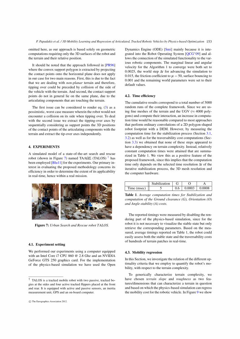
A simulated model of a state-of-the-art search and rescuerobot (shown in Figure 7) named TAΛΩΣ (TALOS) † hasbeen employed [Blu11] for the experiments. Our primary in-terest in evaluating the proposed methodology concerns itsefficiency in order to determine the extent of its applicabilityin real-time, hence within a real mission.
Figure 7: Urban Search and Rescue robot TALOS.
4.1. Experiment setting
We performed our experiments using a computer equippedwith an Intel Core i7 CPU 860 @ 2.8 Ghz and an NVIDIAGeForce GTS 250 graphics card. For the implementationof the physics-based simulation we have used the Open
† TALOS is a tracked mobile robot with two passive, tracked bo-gies at the sides and four active tracked flippers placed at the frontand rear. It is equipped with active and passive sensors, an inertiameasurement unit, GPS and an on-board computer.
Dynamics Engine (ODE) [Smi] mainly because it is inte-grated into the Robot Operating System [QCG∗09] and al-lows the connection of the simulated functionality to the var-ious robotic components. The marginal linear and angularvelocity for the Algorithm 1 to converge were both set to0.0025, the world step ∆t for advancing the simulation to0.015, the friction coefficient to µ = 50, surface bouncing to0.001 and the remaining world parameters were set to theirdefault values.
4.2. Time efficiency
The cumulative results correspond to a total number of 5000random runs of the complete framework. Since we are us-ing fine meshes of the terrain and the UGV (≈ 4000 poly-gons) and compute their interaction, an increase in computa-tion time would be reasonable compared to most approachesthat perform ordinary convolutions of a 2D polygon-shapedrobot footprint with a DEM. However, by measuring thecomputation time for the stabilization process (Section 3.1,3.2) as well as for the traversability cost computations (Sec-tion 3.3) we obtained that none of these steps appeared tohave a dependency on terrain complexity. Instead, relativelyconstant computation times were attained that are summa-rized in Table 1. We view this as a positive feature of theproposed framework, since this implies that the computationtime only depends on the selected time resolution ∆t of theiterative stabilization process, the 3D mesh resolution andthe computer hardware.
Stabilization G O ATime (msec) 5 0.6 0.0003 0.0008
Table 1. Average computation times for Stabilization andcomputation of the Ground clearance (G), Orientation (O)and Angle-stability (A) costs.
The reported timings were measured by disabling the ren-dering part of the physics-based simulation, since for therobot it is not necessary to visualize the stable state but onlyretrieve the corresponding parameters. Based on the mea-sured, average timings reported on Table 1, the robot couldeasily assess both the stable state and the traversability costsof hundreds of terrain patches in real-time.
4.3. Mobility regression
In this Section, we investigate the relation of the different op-timality criteria that we employ to quantify the robot’s mo-bility, with respect to the terrain complexity.
To generically characterize terrain complexity, wehave chosen terrain slope and roughness as two fea-tures/dimensions that can characterize a terrain in questionand based on which the physics-based simulation can regressthe mobility cost for the robotic vehicle. In Figure 9 we show
c© The Eurographics Association 2012.
153
P. Papadakis et al. / 3D Mobility Learning and Regression of Articulated, Tracked Robotic Vehicles by Physics-based Optimization
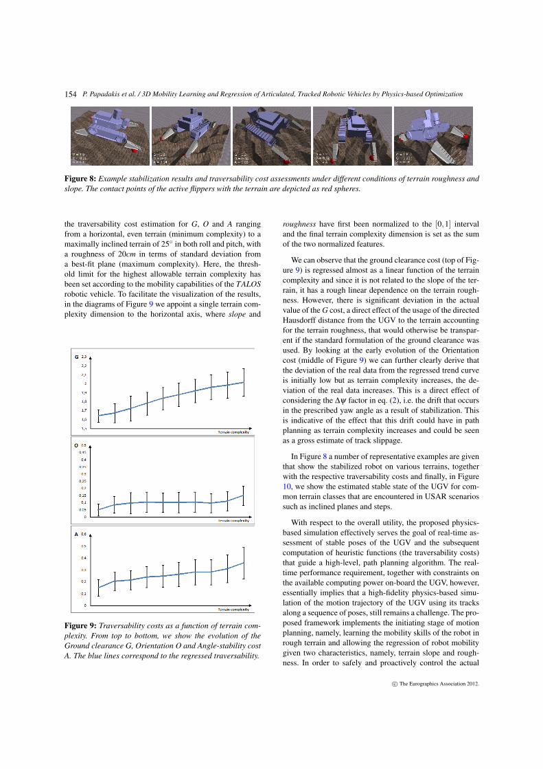
Figure 8: Example stabilization results and traversability cost assessments under different conditions of terrain roughness andslope. The contact points of the active flippers with the terrain are depicted as red spheres.
the traversability cost estimation for G, O and A rangingfrom a horizontal, even terrain (minimum complexity) to amaximally inclined terrain of 25 in both roll and pitch, witha roughness of 20cm in terms of standard deviation froma best-fit plane (maximum complexity). Here, the thresh-old limit for the highest allowable terrain complexity hasbeen set according to the mobility capabilities of the TALOSrobotic vehicle. To facilitate the visualization of the results,in the diagrams of Figure 9 we appoint a single terrain com-plexity dimension to the horizontal axis, where slope and
Figure 9: Traversability costs as a function of terrain com-plexity. From top to bottom, we show the evolution of theGround clearance G, Orientation O and Angle-stability costA. The blue lines correspond to the regressed traversability.
roughness have first been normalized to the [0,1] intervaland the final terrain complexity dimension is set as the sumof the two normalized features.
We can observe that the ground clearance cost (top of Fig-ure 9) is regressed almost as a linear function of the terraincomplexity and since it is not related to the slope of the ter-rain, it has a rough linear dependence on the terrain rough-ness. However, there is significant deviation in the actualvalue of the G cost, a direct effect of the usage of the directedHausdorff distance from the UGV to the terrain accountingfor the terrain roughness, that would otherwise be transpar-ent if the standard formulation of the ground clearance wasused. By looking at the early evolution of the Orientationcost (middle of Figure 9) we can further clearly derive thatthe deviation of the real data from the regressed trend curveis initially low but as terrain complexity increases, the de-viation of the real data increases. This is a direct effect ofconsidering the ∆ψ factor in eq. (2), i.e. the drift that occursin the prescribed yaw angle as a result of stabilization. Thisis indicative of the effect that this drift could have in pathplanning as terrain complexity increases and could be seenas a gross estimate of track slippage.
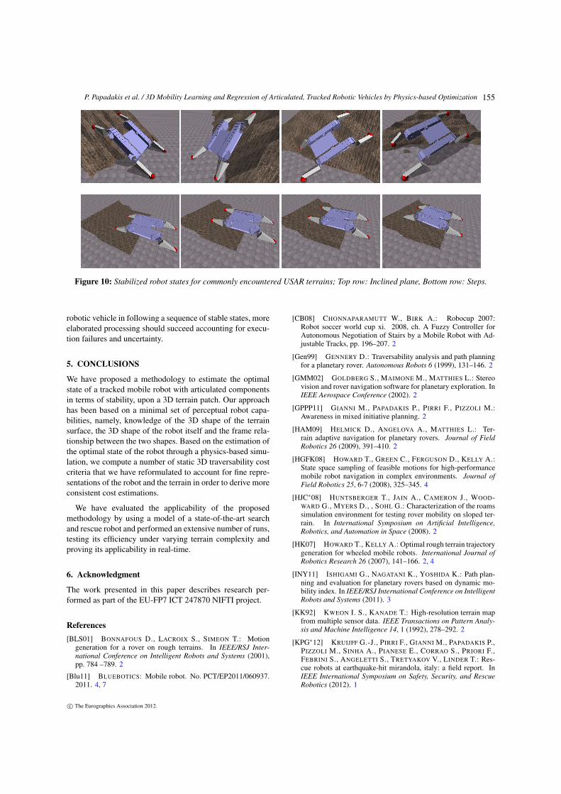
In Figure 8 a number of representative examples are giventhat show the stabilized robot on various terrains, togetherwith the respective traversability costs and finally, in Figure10, we show the estimated stable state of the UGV for com-mon terrain classes that are encountered in USAR scenariossuch as inclined planes and steps.
With respect to the overall utility, the proposed physics-based simulation effectively serves the goal of real-time as-sessment of stable poses of the UGV and the subsequentcomputation of heuristic functions (the traversability costs)that guide a high-level, path planning algorithm. The real-time performance requirement, together with constraints onthe available computing power on-board the UGV, however,essentially implies that a high-fidelity physics-based simu-lation of the motion trajectory of the UGV using its tracksalong a sequence of poses, still remains a challenge. The pro-posed framework implements the initiating stage of motionplanning, namely, learning the mobility skills of the robot inrough terrain and allowing the regression of robot mobilitygiven two characteristics, namely, terrain slope and rough-ness. In order to safely and proactively control the actual
c© The Eurographics Association 2012.
154
P. Papadakis et al. / 3D Mobility Learning and Regression of Articulated, Tracked Robotic Vehicles by Physics-based Optimization
Figure 10: Stabilized robot states for commonly encountered USAR terrains; Top row: Inclined plane, Bottom row: Steps.
robotic vehicle in following a sequence of stable states, moreelaborated processing should succeed accounting for execu-tion failures and uncertainty.
5. CONCLUSIONS
We have proposed a methodology to estimate the optimalstate of a tracked mobile robot with articulated componentsin terms of stability, upon a 3D terrain patch. Our approachhas been based on a minimal set of perceptual robot capa-bilities, namely, knowledge of the 3D shape of the terrainsurface, the 3D shape of the robot itself and the frame rela-tionship between the two shapes. Based on the estimation ofthe optimal state of the robot through a physics-based simu-lation, we compute a number of static 3D traversability costcriteria that we have reformulated to account for fine repre-sentations of the robot and the terrain in order to derive moreconsistent cost estimations.
We have evaluated the applicability of the proposedmethodology by using a model of a state-of-the-art searchand rescue robot and performed an extensive number of runs,testing its efficiency under varying terrain complexity andproving its applicability in real-time.
6. Acknowledgment
The work presented in this paper describes research per-formed as part of the EU-FP7 ICT 247870 NIFTI project.
References[BLS01] BONNAFOUS D., LACROIX S., SIMEON T.: Motion
generation for a rover on rough terrains. In IEEE/RSJ Inter-national Conference on Intelligent Robots and Systems (2001),pp. 784 –789. 2
[Blu11] BLUEBOTICS: Mobile robot. No. PCT/EP2011/060937.2011. 4, 7
[CB08] CHONNAPARAMUTT W., BIRK A.: Robocup 2007:Robot soccer world cup xi. 2008, ch. A Fuzzy Controller forAutonomous Negotiation of Stairs by a Mobile Robot with Ad-justable Tracks, pp. 196–207. 2
[Gen99] GENNERY D.: Traversability analysis and path planningfor a planetary rover. Autonomous Robots 6 (1999), 131–146. 2
[GMM02] GOLDBERG S., MAIMONE M., MATTHIES L.: Stereovision and rover navigation software for planetary exploration. InIEEE Aerospace Conference (2002). 2
[GPPP11] GIANNI M., PAPADAKIS P., PIRRI F., PIZZOLI M.:Awareness in mixed initiative planning. 2
[HAM09] HELMICK D., ANGELOVA A., MATTHIES L.: Ter-rain adaptive navigation for planetary rovers. Journal of FieldRobotics 26 (2009), 391–410. 2
[HGFK08] HOWARD T., GREEN C., FERGUSON D., KELLY A.:State space sampling of feasible motions for high-performancemobile robot navigation in complex environments. Journal ofField Robotics 25, 6-7 (2008), 325–345. 4
[HJC∗08] HUNTSBERGER T., JAIN A., CAMERON J., WOOD-WARD G., MYERS D., , SOHL G.: Characterization of the roamssimulation environment for testing rover mobility on sloped ter-rain. In International Symposium on Artificial Intelligence,Robotics, and Automation in Space (2008). 2
[HK07] HOWARD T., KELLY A.: Optimal rough terrain trajectorygeneration for wheeled mobile robots. International Journal ofRobotics Research 26 (2007), 141–166. 2, 4
[INY11] ISHIGAMI G., NAGATANI K., YOSHIDA K.: Path plan-ning and evaluation for planetary rovers based on dynamic mo-bility index. In IEEE/RSJ International Conference on IntelligentRobots and Systems (2011). 3
[KK92] KWEON I. S., KANADE T.: High-resolution terrain mapfrom multiple sensor data. IEEE Transactions on Pattern Analy-sis and Machine Intelligence 14, 1 (1992), 278–292. 2
[KPG∗12] KRUIJFF G.-J., PIRRI F., GIANNI M., PAPADAKIS P.,PIZZOLI M., SINHA A., PIANESE E., CORRAO S., PRIORI F.,FEBRINI S., ANGELETTI S., TRETYAKOV V., LINDER T.: Res-cue robots at earthquake-hit mirandola, italy: a field report. InIEEE International Symposium on Safety, Security, and RescueRobotics (2012). 1
c© The Eurographics Association 2012.
155
P. Papadakis et al. / 3D Mobility Learning and Regression of Articulated, Tracked Robotic Vehicles by Physics-based Optimization
[LF09] LIKHACHEV M., FERGUSON D.: Planning long dynami-cally feasible maneuvers for autonomous vehicles. InternationalJournal of Robotics Research 28 (2009), 933–945. 4
[LRH94] LANGER D., ROSENBLATT J., HEBERT M.: Abehavior-based system for off-road navigation. IEEE Transac-tions on Robotics and Automation 10, 6 (1994), 776–783. 2
[ME85] MORAVEC H., ELFES A.: High resolution maps fromwide angle sonar. In IEEE International Conference on Roboticsand Automation (1985). 2
[MF68] MCGHEE R., FRANK A.: On the stability properties ofquadruped creeping gaits. Mathematical Biosciences 3, 0 (1968),331 – 351. 7
[ONY∗11] OKADA Y., NAGATANI K., YOSHIDA K., TA-DOKORO S., YOSHIDA T., KOYANAGI E.: Shared autonomysystem for tracked vehicles on rough terrain based on continuousthree-dimensional terrain scanning. Journal of Field Robotics 28,6 (2011), 875–893. 2, 3
[PP11] PAPADAKIS P., PIRRI F.: Consistent pose normalizationof non-rigid shapes using one-class support vector machines.In IEEE Computer Vision and Pattern Recognition, Workshopon Non-rigid Shape Analysis and Deformable Image Alignment(2011), pp. 23–30. 4
[PR96] PAPADOPOULOS E., REY D.: A new measure of tipoverstability margin for mobile manipulators. In IEEE InternationalConference on Robotics and Automation (1996). 5, 7
[QCG∗09] QUIGLEY M., CONLEY K., GERKEY B., FAUST J.,FOOTE T., LEIBS J., WHEELER R., NG A.: Ros: an open-sourcerobot operating system. In ICRA Workshop on Open Source Soft-ware (2009). 8
[SGS05] SCHOLKOPF B., GIESEN J., SPALINGER S.: Kernelmethods for implicit surface modeling. In Advances in NeuralInformation Processing Systems (2005), pp. 1193–1200. 4
[Smi] SMITH R.: Ode, http://www.ode.org/. 8
[SSS∗00] SINGH S., SIMMONS R., SMITH T., STENTZ A.,VERMA V., YAHJA A., SCHWEHR K.: Recent progress in localand global traversability for planetary rovers. In IEEE Interna-tional Conference on Robotics and Automation (2000). 2
[TD99] TAX D., DUIN R.: Support vector domain description.Pattern Recognition Letters 20, 11-13 (1999), 1191 – 1199. 4
[VB04] VUKOBRATOVIC M., BOROVAC N.: Zero-moment point- thirty five years of its life. International Journal of HumanoidRobotics 1, 1 (2004), 157–173. 6
[VDH06] VANDAPEL N., DONAMUKKALA R. R., HEBERT M.:Unmanned ground vehicle navigation using aerial ladar data. TheInternational Journal of Robotics Research 25, 1 (2006), 31–51.2
c© The Eurographics Association 2012.
156