3d pose estimation and segmentation using specular...
TRANSCRIPT
3D Pose Estimation and Segmentation using Specular Cues
Ju Yong Chang1,∗ Ramesh Raskar2 Amit Agrawal11Mitsubishi Electric Research Labs (MERL), 201 Broadway, Cambridge, MA
2MIT Media Lab, 20 Ames St., Cambridge, [email protected]
Abstract
We present a system for fast model-based segmentationand 3D pose estimation of specular objects using appear-ance based specular features. We use observed (a) specularreflection and (b) specular flow as cues, which are matchedagainst similar cues generated from a CAD model of theobject in various poses. We avoid estimating 3D geome-try or depths, which is difficult and unreliable for specu-lar scenes. In the first method, the environment map of thescene is utilized to generate a database containing synthe-sized specular reflections of the object for densely sampled3D poses. This database is compared with captured imagesof the scene at run time to locate and estimate the 3D poseof the object. In the second method, specular flows are gen-erated for dense 3D poses as illumination invariant featuresand are matched to the specular flow of the scene.
We incorporate several practical heuristics such as useof saturated/highlight pixels for fast matching and nor-mal selection to minimize the effects of inter-reflectionsand cluttered backgrounds. Despite its simplicity, our ap-proach is effective in scenes with multiple specular objects,partial occlusions, inter-reflections, cluttered backgroundsand changes in ambient illumination. Experimental resultsdemonstrate the effectiveness of our method for various syn-thetic and real objects.
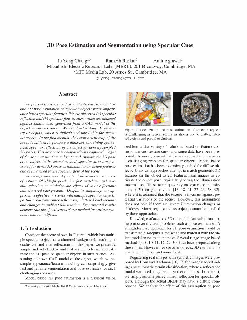
1. IntroductionConsider the scene shown in Figure 1 which has multi-
ple specular objects on a cluttered background, resulting inocclusions and inter-reflections. In this paper, we present asimple and yet effective and fast system to locate and esti-mate the 3D pose of specular objects in such scenes. As-suming a known CAD model of the object, we show thatsimple appearance/feature matching can surprisingly givefast and reliable segmentation and pose estimates for suchchallenging scenarios.
Model based 3D pose estimation is a classical vision
∗Currently at Digital Media R&D Center in Samsung Electronics
Figure 1. Localization and pose estimation of specular objectsis challenging in typical scenes as shown due to clutter, inter-reflections and partial occlusions.
problem and a variety of solutions based on feature cor-respondences, texture cues, and range data have been pro-posed. However, pose estimation and segmentation remainsa challenging problem for specular objects. Model basedpose estimation has been extensively studied for diffuse ob-jects. Classical approaches attempt to match geometric 3Dfeatures on the object to 2D features from images to es-timate the object pose, typically ignoring the illuminationinformation. These techniques rely on texture or intensitycues in 2D images or video [15, 18, 21, 22, 23, 28, 32],where it is assumed that the texture is invariant against po-tential variations of the scene. However, this assumptiondoes not hold if there are severe illumination changes orshadows. Moreover, textureless objects cannot be handledby these approaches.
Knowledge of accurate 3D or depth information can alsohelp in several vision problems such as pose estimation. Astraightforward approach for 3D pose estimation would beto estimate 3D/depths in the scene and match it with the ob-ject model to estimate the pose. Several range image basedmethods [4, 8, 10, 11, 12, 29, 30] have been proposed alongthose lines. However, for specular objects, 3D estimation ischallenging, noisy, and non-robust.
Registering real images with synthetic images were pro-posed by Horn and Bachman [16, 17] for image understand-ing and automatic terrain classification, where a reflectancemodel was used to generate synthetic images. In contrast,we simply assume perfect mirror reflection for specular ob-jects, although the actual BRDF may have a diffuse com-ponent. We analyze the effect of this assumption on pose
estimation.Recently, [3] proposed to use multiple monocular cues
including polarization and synthesized CAD model imagesfor 3D pose estimation. However, we only use image inten-sities and propose to use specular flow as another cue. Spec-ular reflection has been used for 3D pose refinement [20],starting from a known coarse pose. Their approach usesboth texture and specular cues and handles only a singleobject in the scene. However, absolute pose estimation andsegmentation of specular objects is much more difficult thanpose refinement. We handle multiple specular objects incluttered environments. In addition, we specifically use amirror sphere to obtain the environment map, which is usedto render the synthetic images.
Note that the process of pose estimation indirectly givessegmentation (localization of the object). For matching realphotos to synthetic images by rendering the specular ob-ject requires additional information about the illumination,which is often simplified and represented by the 2D envi-ronment map. In our second approach, the requirement ofthe environment map can be removed by matching specularflows as an illumination-invariant feature.
As computational power keeps on increasing, one canuse simple, brute-force methods for challenging visionproblems such as pose estimation. Our goal is to developa simple, fast and practical system. We report recognitiontime of few seconds on commodity hardware (without usingGPUs) by matching 25000 synthesized images. We proposepractical heuristics such as the use of saturated/highlightpixels for fast matching and normal selection to minimizethe effects of inter-reflections and cluttered backgrounds.
1.1. Benefits and limitationsWe demonstrate that the proposed system handles chal-
lenging scenes with partial occlusions, background clut-ters, and inter-reflections. Our method does not require3D/depths estimation of the target scene and is conceptu-ally simple and easy to implement. The limitations of ourapproach are as follows.
• We require placing a calibration object (mirror sphere)in the target scene to capture the environment map.
• We require the environment map to be of sufficientlyhigh frequency to induce variations in the synthesizedimages.
• The specular-flow based method requires specific mo-tion of the environment to induce the specular flow.
• Planar surfaces and surfaces with low curvature cannotbe handled.
1.2. Related work3D pose refinement using specular reflections has been
proposed in [20]. Given a short image sequence and initial
pose estimates computed by the standard template match-ing, their approach first separate Lambertian and specularcomponents for each frame and derive environment mapsfrom the estimated specular images. The environment mapsare then aligned in conjunction with image textures to in-crease the accuracy of the pose refinement. Similar to [20],our approach also exploits specular reflections for 3D poseestimation. However, we focus on absolute pose estimationand segmentation of specular objects in a scene rather thanpose refinement. Our approach does not require the objectto be textured to compute an initial pose estimate and canestimate the absolute 3D pose directly from specular reflec-tion.
Specular surface reconstruction: A wide range ofmethods derive sparse 3D shape information from the iden-tification and/or tracking of distorted reflections of lightsources and special features [5, 6, 26, 31, 34]. Dense mea-surements can also be obtained based on the general frame-work of light-path triangulation as shown in [7, 19, 24].However, these methods usually need to perform accuratecalibration and control of environments surrounding the tar-get object and require several input images. On the otherhand, our method uses a simple mirror-like sphere as acalibration object and requires just two input images (or aHDR image). In addition, we do not need to estimate the3D/depths in the scene.
Specular flow [27] refers to the flow induced by a smallenvironmental motion on the image plane for a specular ob-ject. It can be utilized for specular surface reconstructionwithout any environment calibration as shown in [1, 33] forsynthetic examples, or for detecting specular surfaces in im-age [9]. Surface reconstruction using specular flow requiresa pair of linear PDE’s to be solved using initial conditions,which are not easy to estimate in real situations. In addi-tion, the accuracy of 3D reconstruction using specular flowhas not been established for real scenes yet. We show thatspecular flow can also be used as a cue for 3D pose estima-tion. Since we avoid 3D reconstruction, we only require togenerate the specular flows corresponding to different ob-ject poses for subsequent matching.
2. Problem statementGiven a scene consisting of several specular objects, our
goal is to simultaneously locate and estimate the absolute3D pose for a given object using its CAD model. We as-sume that the target object has perfect mirror-like BRDF,although in practice the actual BRDF may differ. The 3Dpose is defined by a 3D translation vector (x, y, z) and ro-tation angles (θ, φ, σ). Additionally, it is assumed that thedistance between the camera and the target object is approx-imately known (z ≈ z0). This is a reasonable assumptionunder many controlled applications. All equations in thispaper are derived from the assumption of the orthographicprojection for notational simplicity. But they can be easily

3D Model Real Environment Maps
...
Matching(on-line)
Synthesizing(off-line)
+
Reference Specular Images
Real Input Images with different exposure times
Figure 2. Overview of environment map based pose estimation.
generalized to the perspective case and we actually use theperspective projection for experiments.
We pursue a top-down approach, where we assumeknown high level information such as the object’s geomet-ric and photometric properties and/or illumination informa-tion, and then generate and utilize the low level featuresobservable in 2D image to estimate 3D pose. Specifically,we render the given 3D model with the mirror-like BRDFand estimate the best 3D pose and location of the object,which makes the resultant synthetic specular features wellmatched to the features in the real input image. We use abrute-force matching strategy to obtain a coarse pose, whichis further refined using optimization techniques. Now wedescribe two methods that utilize (a) rendered specular im-ages and (b) specular flows as the cues for matching.
3. Environment map based pose estimationIn this method, we first measure the environmental illu-
mination. In general, this information can be formulatedby a 5D plenoptic function [2]. We assume that the tar-get object is sufficiently far away from its surrounding en-vironments, which simplifies it to a 2D environment map.Specifically, we put a small mirror-like sphere in the targetscene and use its image as the 2D environment map. To han-dle wide dynamic range, we capture two environment maps,EL and ES at large and small exposure times respectively.
3.1. Generating synthetic specular imagesLet the object surface S(x, y) = (x, y, f(x, y)) be
viewed orthographically from above and illuminated by afar-field environment E as in Figure 3. Let r = (0, 0, 1) bethe viewing direction, n(x, y) the surface normal at surface
nri
xy
z
E
yxI ,
yxf ,
Figure 3. Image formation for a specular object.
point (x, y, f(x, y)), and i(x, y) the direction of the incidentlight ray which can be represented as two spherical anglesα(x, y) (elevation) and β(x, y) (azimuth). Using the law ofthe reflection (i = 2(n · r)n− r), the spherical angles of theincident light ray in terms of surface derivatives are givenby α = tan−1( 2‖∇f‖
1−‖∇f‖2 ) and β = tan−1( fy
fx). Then the
image of the specular surface is given by
I(x, y) = E(α, β)= E(tan−1( 2‖∇f‖
1−‖∇f‖2 ), tan−1( fy
fx)) . (1)
The above equation can be used to generate referencespecular images corresponding to pre-defined pose hy-potheses, assuming known CAD model. The number ofthese pose hypotheses should be sufficiently large in orderto cover large pose variations. We uniformly sample the ro-tation angles to generate 25000 − 50000 reference imagesby environment mapping [13, 14]. Let RL
θ,φ,σ and RSθ,φ,σ
denote the synthetic specular images using EL and ES asthe environment map respectively.
3.2. Matching for pose estimationLet IL and IS denote the two input images captured us-
ing the same exposure times used for environment maps.We compare the input images with the reference specularimages corresponding to densely sampled pose hypothesesand then obtain a coarse pose estimate as the best matchedpose hypothesis. We propose following two heuristics toimprove the speed and reliability of matching.
Using highlights/saturated pixels: In general, the spec-ular image consists of highlights (saturated pixels) due tobright light sources. For mirror-like or metallic objects, thehighlight pixels are extracted by applying a simple thresh-old to the short exposure images. The resulting binary im-ages are referred to as highlight images. Let DI and DR
refer to the distance transform of the highlight images cor-responding to the input and reference highlight images. Weuse the highlight pixels for fast localization/pose estimation

by minimizing
CHL(θ, φ, σ, x, y) =
∑(u,v)(DI(u, v) − Dθ,φ,σ
R (u − x, v − y))2
NHL,
where (u, v) is pixel coordinate and NHL denotes the num-ber of highlight pixels.
The highlight based cost function has several advantages.Firstly, the highlights are usually sparse in the input image,so they can be used as a strong constraint for restrictingthe object’s location. Secondly, distance transform makesthe cost distribution smoother. Finally, since the stencil ofthe highlights contains a very small number of pixels, com-puting the above cost function can be done efficiently. Inour experiments, the proposed highlights based cost func-tion converges well to a global minimum rapidly.
Normal selection for geometrically reliable pixels: Toaccount for inter-reflections and background clutter, we pro-pose a normal selection procedure to use only geometri-cally reliable pixels by avoiding illumination directions cor-responding to small elevation angles. Our geometric sten-cil selection is as follows. First, we compute the incidentlight ray direction i for each pixel of the reference imageusing the law of reflection and known surface normal forthe given pose. Then, the reliability of the pixel informa-tion is defined by considering the illumination direction asshown in Figure 4. Illumination directions correspondingto small elevation angles are usually less reliable because ofinter-reflections between the specular object and its neigh-bors. We use only those specular pixels for which incidentlight rays have the elevation angles larger than 90 degrees.We define a second cost function based on geometricallyreliable pixels
CGR(θ, φ, σ, x, y) = 1−g(IL(u, v), RLθ,φ,σ(u−x, v−y)),
where g() denotes the normalized cross correlation (NCC)function. Although it seems natural to use the object’s seg-mentation mask as the stencil for NCC computation, wefound that using only geometrically reliable specular pix-els as the stencil produces better results in practice.
Coarse pose estimation: The best match among the ref-erence images is found in two steps. In the first step, foreach rotational pose, the best translation in the image planewith its associated cost is obtained using only the highlightpixels based cost function. For this translation optimization,we use the downhill simplex algorithm [25]. As the initialpoints for the downhill simplex algorithm, we use the threecorner points of the input image. Then the translation is re-fined by performing optimization considering all geometri-cally reliable pixels. Once we have the optimal translationsand cost values for each rotation, we compare these costvalues and choose the rotation with the minimum cost. Werefer to the obtained pose as coarse pose, since it depends
r n2
i2
n1r
i1
reliable unreliable
(a) (b)Figure 4. Reliability computation is illustrated in (a). Illumina-tions from i1 and i2 are considered as reliable and unreliable, re-spectively. Examples of reliable and unreliable pixels for a mirrorsphere are shown in (b).
on the discretization of the database (number of referenceimages).
Pose refinement: Since the above pose estimate is ob-tained by matching the reference images, it is accurate onlyup to the discretization of the database. The estimated 3Dpose is further refined by optimizing over all five pose pa-rameters using a steepest descent algorithm, where the gra-dient at each step is computed numerically. We minimizethe reliable pixels based cost function and initialize the poseparameters as the coarse pose estimate obtained above.
4. Specular flow based pose estimationIn this method, we utilize specular flow [27] as fea-
tures for matching, which is defined as the optical flow in-duced by the camera or scene/object motion in the imagesfor specular reflection. While previously specular flow hasbeen used for 3D shape reconstruction [1], we propose touse it for 3D pose estimation. Similarly to [1], we keep therelative pose between the camera and object fixed, and onlyassume environmental motion. We capture two images ofthe target scene under pre-defined rotation of environmentaround known direction (e.g. camera’s viewing direction).We use a simple block matching algorithm to obtain the 2Ddisplacement vectors for each pixel.
Note that since the relative pose between the camera andthe scene is fixed, optical flow is mainly observed on specu-lar objects due to illumination change. Therefore, in a clut-tered scene, this motion cue can be used for strongly con-straining the specular object’s location, similar to the high-lights in the environment map based method.
4.1. Generating reference specular flowsThe angular motion of far-field environment can be rep-
resented as a vector field ω(α, β) = (dαdt , dβ
dt ) on the unitsphere. This environment motion induces a specular flowu(x, y) = (dx
dt , dydt ) on the image plane. This flow is related
to the environment motion through the Jacobian J and canbe written as
u = J−1ω, (2)

3D Model
Predefined Small Rotationof Environment Map
Real Input Images under predefined small rotation
Matching(on-line)
Synthesizing(off-line)
+
Reference Specular Flows / Motion Segmentations
...
Input Specular Flow / Motion SegmentationComputing
(on-line)
Figure 5. Overview of specular flow based pose estimation.
where the Jacobian can be expressed in terms of surfaceshape as
J � ∂(α, β)∂(x, y)
=
(fxfxx+fyfxy
‖∇f‖·(1+‖∇f‖2)fxfxy+fyfyy
‖∇f‖·(1+‖∇f‖2)fxfxy−fyfxx
2‖∇f‖2fxfyy−fyfxy
2‖∇f‖2
)
.
(3)This equation can be used for generating reference specularflows corresponding to densely sampled pose hypotheses.Let the reference specular flow image synthesized from ori-entation (θ, φ, σ) be denoted by Rθ,φ,σ.
The specular flow does not depend on the illuminationinformation but only on the motion and the object’s shapeand pose. Therefore, under the assumption that the mo-tion and the object’s shape are given, it can be used asthe illumination-invariant feature for pose estimation. Notethat the determinant of J can be written as det(J) =2K(1+‖∇f‖2)
‖∇f‖ , where K is the Gaussian curvature of the sur-face. Thus, planar surfaces and surfaces with low curvaturescannot be handled by this method. In addition, for the spec-ular flow to be estimated reliably, the environment shouldhave sufficiently high frequency variations.
4.2. Matching specular flowsSimilarly to the previous method, the reference specular
flows are compared with the input specular flow I to esti-mate a coarse pose as follows:
Using motion segmentation for fast matching: We de-fine a motion segmentation image as the binary image indi-cating the presence/absence of specular flow. As discussed,since the relative pose of the camera and object is fixed, themotion segmentation image gives strong cues for location
of specular objects, similar to saturated pixels in environ-ment map based approach. Thus, a fast location search canbe done using motion segmentation image.
Again, let DI and DR denote the distance transformationof motion segmentation images for scene specular flow andthe reference specular flow Rθ,φ,σ respectively. A motionsegmentation based cost function is defined as
CMS(θ, φ, σ, x, y) =
∑(u,v)(DI(u, v) − Dθ,φ,σ
R (u − x, v − y))2
NMS,
where the summation is carried out for motion segmenta-tion pixels of Rθ,φ,σ and NMS denotes the number of suchpixels.
Using specular flow: We define a matching error be-tween the input specular flow I(u, v) with the translatedreference specular flow Rθ,φ,σ(u − x, v − y). In reality,specular flow contains many outliers, so simple cost func-tions such as sum of squared differences (SSD) does notwork well. Instead, we use a robust cost function based onthe number of inlier pixels. First, we define the inlier pix-els as ones where the difference between the input specularflow vector I(u, v) and the reference specular flow vectorRθ,φ,σ(u − x, v − y) is less than a small threshold (1.0 inour experiments). Then, the matching cost function CSF isdefined as
CSF (θ, φ, σ, x, y) = −|M|,where M is the set of inlier pixels.
Coarse pose estimation: First, translation (x, y) is opti-mized for each rotation (θ, φ, σ) by using the downhill sim-plex algorithm and motion segmentation based cost func-tion, initialized by three corner points of the input image.Then translation is refined by minimizing CSF . Finally, bycomparing best costs from all translation optimized poses,the best rotation values are chosen.
Pose refinement: Using the above coarse pose as theinitial starting pose, we refine all five DOF parameters forpose by minimizing the SSD cost function.
5. Experimental resultsIn this section, we present the results of both approaches
on various synthetic and real objects. All experiments havebeen performed on a standard PC with 2.66 GHz Intel quad-core CPU and 3.25 GB RAM. Before pose estimation, ref-erence synthetic images in Section 3 or reference specu-lar flows in Section 4 are synthesized (using OpenGL) andstored off-line. The resolutions of the input images and thereference images are 400×300 and 100×100, respectively.
For the environment map based method using 25000 ref-erence images, on average our approach takes 2.26 and 0.44seconds for coarse pose estimation and fine pose refine-ment respectively. The corresponding numbers for spec-ular flow based approach are 32.99 and 0.49 seconds re-spectively. Note that the computation time is dominated
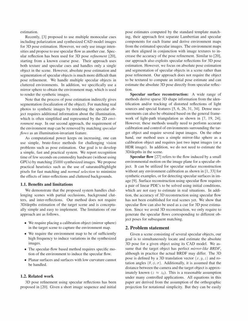
x (mm) y (mm) θ (◦) φ (◦) σ (◦)Env. Map 0.29 0.39 2.12 1.64 1.69Spec. Flow 0.46 0.39 3.64 2.85 2.06
Table 1. Average pose errors for successful pose estimates (max-imum error less than 1 mm and 10◦ for translation and rotationrespectively).
by coarse pose estimation which utilizes brute-force match-ing and the downhill simplex algorithm. We believe thatthis process can be parallelized by using modern graphicsprocessing units (GPUs) similarly to [12], and could be re-duced.
5.1. Synthetic objectsFor the quantitative evaluation of our methods, we per-
formed experiments using a synthetic object, but with a realenvironment map captured using a mirror ball. The refer-ence synthetic images are generated using the known CADmodel and the environment map, assuming perfect mirror-like BRDF. To evaluate the pose estimation accuracy, wegenerate a noisy input image using a random pose andadded Gaussian noise. For the specular flow based method,two input images are generated by assuming small rotation(5◦) of the environment map. The input specular flows aresimilarly generated using a random pose for the object.
We compare the results with ground truth pose parame-ters. The resultant pose is regarded as success if the maxi-mum pose errors are less than 1 mm and 10◦ for translationand rotation angles respectively. The average pose errors forsuccessful pose estimates after 50 trials for both methodsare shown in Table 1. The environment map based methodappears to be more accurate than the specular flow basedmethod. Horn and Bachman [16, 17] argues that using pixelintensities instead of first extracting features is better formatching real images to synthetic images. Our results alsoshow that the environment map based method is more accu-rate than the specular flow based method.
5.2. Robustness analysisNote that we made simplifying assumptions on BRDF
(mirror-like) as well as assumed that exact geometry and en-vironment map is available. In practice, however, the BRDFcould consist of diffuse component as well as a specularlobe. In addition, the CAD model may not be accurate andthe changes in ambient illumination could effect the envi-ronment map. We investigate how these deviations degradethe performance of our system.
We first generate reference synthetic images/specularflows from noiseless 3D model assuming perfect specu-lar reflection and known environment map. We then ap-ply both techniques to input images synthesized by assum-ing variations in (a) object geometry (b) object reflectance,and (c) environment map. The resultant success rates andmean/variance of rotational pose errors are shown in Ta-
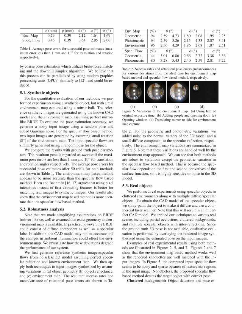
Env. Map (%) θ (◦) φ (◦) σ (◦)Geometric 94 2.59 4.73 1.80 2.08 1.95 2.25Photometric 94 2.59 5.26 2.15 4.33 2.07 3.41Environment 95 2.36 4.29 1.86 2.68 1.87 2.51
Spec. Flow (%) θ (◦) φ (◦) σ (◦)Geometric 44 5.01 6.86 2.66 2.72 3.38 3.36Photometric 80 3.28 5.43 2.40 2.59 2.01 3.22
Table 2. Success rates and rotational pose errors (mean/variance)for various deviations from the ideal case for environment mapbased method and specular flow based method, respectively.
(a) (b) (c) (d)Figure 6. Variations of the environment map. (a) Using half oforiginal exposure time. (b) Adding people and opening door. (c)Opening window. (d) Translating mirror to side for environmentmap capture.
ble 2. For the geometric and photometric variations, weadded noise to the normal vectors of the 3D model and asmall diffuse component to the specular reflection, respec-tively. The environment map variations are summarized inFigure 6. Note that these variations are handled well by theenvironment map approach. We can see that both methodsare robust to variations except the geometric variation inthe specular flow based method. This is because the spec-ular flow depends on the first and second derivatives of thesurface function, so it is highly sensitive to noise in the 3Dmodel.
5.3. Real objectsWe performed real experiments using specular objects in
cluttered environments along with multiple diffuse/specularobjects. To obtain the CAD model of the specular object,we spray-paint the object to make it diffuse and use a com-mercial laser scanner. Note that this will result in an imper-fect CAD model. We applied our techniques to various realscenes including partial occlusions, cluttered backgrounds,and multiple specular objects with inter-reflections. Sincethe ground truth 3D pose is not available, qualitative eval-uation is performed by overlaying the rendered image syn-thesized using the estimated pose on the input images.
Examples of real experimental results using both meth-ods are illustrated in Figures 2, 5, and 7. Figures 2 and 7show that the environment map based method works wellas the rendered silhouettes are well matched with the in-put images. In Figure 5, the computed input specular flowseems to be noisy and sparse because of textureless regionsin the input image. Nonetheless, the proposed specular flowbased method detects the target object with correct pose.
Cluttered background: Object detection and pose es-
(a)
(b)
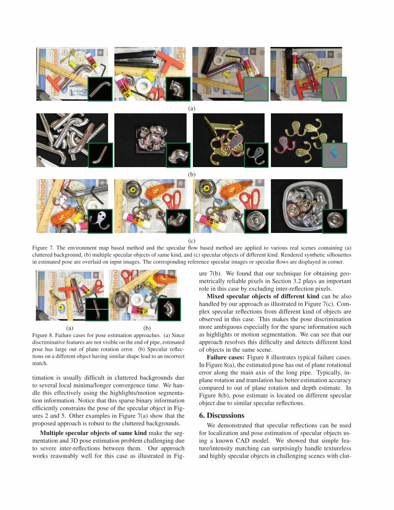
(c)Figure 7. The environment map based method and the specular flow based method are applied to various real scenes containing (a)cluttered background, (b) multiple specular objects of same kind, and (c) specular objects of different kind. Rendered synthetic silhouettesin estimated pose are overlaid on input images. The corresponding reference specular images or specular flows are displayed in corner.
(a) (b)Figure 8. Failure cases for pose estimation approaches. (a) Sincediscriminative features are not visible on the end of pipe, estimatedpose has large out of plane rotation error. (b) Specular reflec-tions on a different object having similar shape lead to an incorrectmatch.
timation is usually difficult in cluttered backgrounds dueto several local minima/longer convergence time. We han-dle this effectively using the highlights/motion segmenta-tion information. Notice that this sparse binary informationefficiently constrains the pose of the specular object in Fig-ures 2 and 5. Other examples in Figure 7(a) show that theproposed approach is robust to the cluttered backgrounds.
Multiple specular objects of same kind make the seg-mentation and 3D pose estimation problem challenging dueto severe inter-reflections between them. Our approachworks reasonably well for this case as illustrated in Fig-
ure 7(b). We found that our technique for obtaining geo-metrically reliable pixels in Section 3.2 plays an importantrole in this case by excluding inter-reflection pixels.
Mixed specular objects of different kind can be alsohandled by our approach as illustrated in Figure 7(c). Com-plex specular reflections from different kind of objects areobserved in this case. This makes the pose discriminationmore ambiguous especially for the sparse information suchas highlights or motion segmentation. We can see that ourapproach resolves this difficulty and detects different kindof objects in the same scene.
Failure cases: Figure 8 illustrates typical failure cases.In Figure 8(a), the estimated pose has out of plane rotationalerror along the main axis of the long pipe. Typically, in-plane rotation and translation has better estimation accuracycompared to out of plane rotation and depth estimate. InFigure 8(b), pose estimate is located on different specularobject due to similar specular reflections.
6. DiscussionsWe demonstrated that specular reflections can be used
for localization and pose estimation of specular objects us-ing a known CAD model. We showed that simple fea-ture/intensity matching can surprisingly handle texturelessand highly specular objects in challenging scenes with clut-

tered background, inter-reflections and partial occlusions.Our approach uses monocular camera images and does notrequire 3D scanning of the target scene. The proposed ap-proach uses simple matching cost functions and optimiza-tion algorithms, and is fast and easy to implement. Fastnearest neighbor search using k-d trees and dimensionalityreduction algorithms can further reduce the computationalcost of our approach.
Apparent limitation of our approach is that both pro-posed methods require specific assumptions such as sparsehighlights have to be observed in the input image or motionhas to be restricted to only the small environmental motion.Removing these assumptions and extending our approach tohandle more general (e.g. partially diffuse and specular) orchallenging (e.g. translucent) objects is an interesting futurework.
Acknowledgements We thank the anonymous reviewersand several members of MERL for helpful suggestions. Wealso thank Jay Thornton, Keisuke Kojima, John Barnwelland Haruhisa Okuda, Mitsubishi Electric, Japan for helpand support.
References
[1] Y. Adato, Y. Vasilyev, O. Ben-Shahar, and T. Zickler. Towarda theory of shape from specular flow. In Proc. Int’l Conf.Computer Vision, 2007.
[2] E. Adelson and J. Bergen. Computational Models for VisualProcessing. MIT Press, 1991.
[3] B. Barrois and C. Wohler. 3d pose estimation based on mul-tiple monocular cues. In BenCOS, 2007.
[4] P. Besl and N. McKay. A method for registration of 3dshapes. IEEE Trans. Pattern Anal. Machine Intell., 1992.
[5] A. Blake. Specular stereo. In Proc. Int’l Joint Conf. on Arti-ficial Intelligence, volume 2, pages 973–976, 1985.
[6] A. Blake and G. Brelstaff. Geometry from specularities. InProc. Int’l Conf. Computer Vision, pages 394–403, 1988.
[7] T. Bonfort, P. Sturm, and P. Gargallo. General specular sur-face triangulation. In Proc. Asian Conf. Computer Vision,pages 872–881, 2006.
[8] Y. Chen and G. Medioni. Object modeling by registration ofmultiple range images. Robotics and Automation, 1991.
[9] A. DelPozo and S. Savarese. Detecting specular surfaces onnatural images. In Proc. Conf. Computer Vision and PatternRecognition, 2007.
[10] N. Gelfand, L. Ikemoto, S. Rusinkiewicz, and M. Levoy. Ge-ometrically stable sampling for the icp algorithm. In 3DIM,2003.
[11] N. Gelfand, N. Mitra, L. Guibas, and H. Pottmann. Robustglobal registration. In Eurographics Symposium on Geome-try Processing, 2005.
[12] M. Germann, M. D. Breitenstein, I. K. Park, and H. Pfister.Automatic pose estimation for range images on the gpu. In3DIM, 2007.
[13] N. Greene. Environment mapping and other applications ofworld projections. IEEE Computer Graphics and Applica-tions, 6(11):21–29, 1986.
[14] P. Haeberli and M. Segal. Texture mapping as a fundamen-tal drawing primitive. In Fourth Eurographics Workshop onRendering, pages 259–266, 1993.
[15] R. Hartley and A. Zisserman. Multiple View Geometry inComputer Vision. Cambridge University Press, 2000.
[16] B. Horn and B. Bachman. Using synthetic images to registerreal images with surface models. Communications of theA.C.M., 21(11):914–924, 1978.
[17] B. Horn and B. Bachman. Registering real images using syn-thetic images. In Artificial Intelligence: An MIT Perspective,volume 2, pages 129–159, 1979.
[18] M. J. Jones and P. Viola. Fast multi-view face detection. InProc. Conf. Computer Vision and Pattern Recognition, 2003.
[19] K. N. Kutulakos and E. Steger. A theory of refractive andspecular 3d shape by light-path triangulation. In Proc. Int’lConf. Computer Vision, pages 1448–1455, 2005.
[20] P. Lagger, M. Salzmann, V. Lepetit, and P. Fua. 3d poserefinement from reflections. In Proc. Conf. Computer Visionand Pattern Recognition, 2008.
[21] V. Lepetit and P. Fua. Monocular model-based 3d tracking ofrigid objects: A survey. Foundations and Trends in ComputerGraphics and Vision, 1(1):1–89, 2005.
[22] D. G. Lowe. Three-dimensional object recognition from sin-gle two-dimensional images. Artificial Intelligence, 31:355–395, 1987.
[23] D. G. Lowe. Fitting parameterized three-dimensional mod-els to images. IEEE Trans. Pattern Anal. Machine Intell.,13:441–450, 1991.
[24] D. Nehab, T. Weyrich, and S. Rusinkiewicz. Dense 3d recon-struction from specularity consistency. In Proc. Conf. Com-puter Vision and Pattern Recognition, 2008.
[25] J. A. Nelder and R. Mead. A simplex method for functionminimization. The Computer Journal, 7(4):308–313, 1965.
[26] M. Oren and S. K. Nayar. A theory of specular surface ge-ometry. Int’l J. Computer Vision, 24(2):105–124, 1997.
[27] S. Roth and M. Black. Specular flow and the recovery of sur-face structure. In Proc. Conf. Computer Vision and PatternRecognition, pages 1869–1876, 2006.
[28] F. Rothganger, S. Lazebnik, C. Schmid, and J. Ponce. 3d ob-ject modeling and recognition using affine-invariant patchesand multi-view spatial constraints. In Proc. Conf. ComputerVision and Pattern Recognition, 2003.
[29] S. Rusinkiewicz, O. Hall-Holt, and M. Levoy. Real-time 3dmodel acquisition. ACM Transactions on Graphics (TOG),21(3):438–446, 2002.
[30] S. Rusinkiewicz and M. Levoy. Efficient variants of the icpalgorithm. In 3DIM, 2001.
[31] S. Savarese, M. Chen, and P. Perona. Local shape from mir-ror reflections. Int’l J. Computer Vision, 64(1):31–67, 2005.
[32] C. Schmid and R. Mohr. Combining greyvalue invariantswith local constraints for object recognition. In Proc. Conf.Computer Vision and Pattern Recognition, 1996.
[33] Y. Vasilyev, Y. Adato, T. Zickler, and O. Ben-Shahar. Densespecular shape from multiple specular flows. In Proc. Conf.Computer Vision and Pattern Recognition, 2008.
[34] P. Zisserman, A. Giblin, and A. Blake. The informationavailable to a moving observer from specularities. Imageand Vision Computing, 7(1):38–42, 1989.