3d reconstruction of crime scenes and design ... · 3d reconstruction of crime scenes and design...
TRANSCRIPT

3D Reconstruction of Crime Scenes and DesignConsiderations for an Interactive Investigation
Tool
Erkan Bostanci
Ankara University, Faculty of Engineering, Computer Engineering Department.Ankara University, Golbasi 50.Yil Yerleskesi, Bahcelievler Mah. 06830, Ankara, Turkey. Tel: +90-203-3300/1767.
e-mail: [email protected]
Abstract—Crime Scene Investigation (CSI) is a carefully planned systematic process with the purpose of acquiring physicalevidences to shed light upon the physical reality of the crime and eventually detect the identity of the criminal. Capturing imagesand videos of the crime scene is an important part of this process in order to conduct a deeper analysis on the digital evidence forpossible hints. This work brings this idea further to use the acquired footage for generating a 3D model of the crime scene. Resultsshow that realistic reconstructions can be obtained using sophisticated computer vision techniques. The paper also discusses anumber of important design considerations describing key features that should be present in a powerful interactive CSI analysistool.
Keywords—Crime scene investigation, forensic science, 3D reconstruction, computer vision, design.
1. Introduction
The environment where a crime was committed,a crime scene, can be considered as the naturalwitness of the crime. This silent witness, indeed,proves to be very helpful in finding crucial evi-dences related to the story of the crime and allowsinvestigators to establish the correct reasoning andhence to gain a valuable insight into how the crimewas committed [1], [2].
It is known that the crime scene must be investi-gated using a detailed systematic approach [3]–[5].The stages of Crime Scene Investigation (CSI) canbe summarized as follows: First stage is receivinginformation about a crime, planning/preparation forthe investigation and eventually arriving at the crime
scene. Upon arrival, a preliminary investigation isperformed for deciding the appropriate equipmentand material for collecting the evidence.
In the meantime, wounded or injured people andcasualties are identified after doctor’s medical ex-amination and wounded or injured people are trans-ferred to the hospital. The next stage is capturingimages or videos of the crime scene [6] and prepar-ing a sketch diagram of the environment which alsoindicates the camera’s positions while the imagesare being captured as shown in Fig. 1. The evidencesfound in the scene e.g. fingerprints, footprints,pieces of clothing, hair, etc. are also shown in thissketch using the identification numbers assignedto them. The distances between these evidences
1
arX
iv:1
512.
0315
6v1
[cs
.CV
] 1
0 D
ec 2
015

Fig. 1. A Gendarmarie CSI team investigatinga crime scene. Figure courtesy of GendarmarieSchools Command.
and the victim’s position are also annotated in thesketch. Following stages comprise the collectionand packaging of the physical evidences in theenvironment. Finally, the evidences are transferredto the forensic laboratory for detailed analysis. Allthese stages (and several sub-stages which were notmentioned here) constitute and require a meticulousprocess for a successful investigation [7].
The work presented here is related to the stagewhere images or videos of the crime scene are cap-tured. Conventionally, the crime scene is capturedby taking a number of photos using several differentviewpoints as well as capturing images of individ-ual items that may prove to be useful evidence.Panoramic images, see Fig. 2(a), also allow viewingthe crime scene from a wider angle. In order toshow the spatial structure of the environment in 3D,rather than relying solely on images or sketches,an approach is to create a 3D model of the crimescene using modelling tools such as 3D Max. Thereare also companies providing tailored software so-lutions for this purpose (e.g. [8]) facilitating the3D modelling process for crime scenes as shownin Fig. 2(b). More recent approaches make use oflaser scanners to reconstruct the crime scene in form
of a point cloud (Fig. 2(c)) which is very useful forrepresenting the 3D structure of the environment [9],[10].
(a)
(b) (c)
Fig. 2. Different approaches used for modellinga crime scene. (a) Using panoramic images.(b) Sketches and 3D modelling. (c) Laser scan-ner generated point clouds. Figures courtesyof [11]–[13] respectively.
Capturing images of the complete scene can pro-vide useful evidence; however, the images can bemisleading due to the very nature of the imagingprocess itself (perspective projection, lens distor-tions, etc. [14]) Panoramic images, likewise, areaffected by similar problems. Manual modellingof the scene is laborious and may not result in arealistic model; though addition of annotations ofdistances between objects can be quite useful. 3Dlaser scanners [15], a technique known as structuredlight, produce accurate point clouds up to a rangeof 120m [16]. The problem with these is that laserbeams projected from the device may not alwaysreflect back to the sensor properly due to transparentsurfaces (e.g. windows) or corners. Concerns related
2
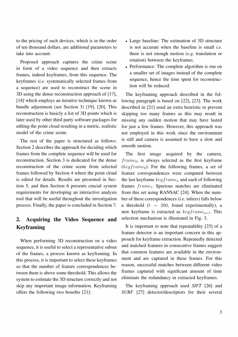
to the pricing of such devices, which is in the orderof ten thousand dollars, are additional parameters totake into account.
Proposed approach captures the crime scenein form of a video sequence and then extractsframes, indeed keyframes, from this sequence. Thekeyframes (i.e. systematically selected frames froma sequence) are used to reconstruct the scene in3D using the dense reconstruction approach of [17],[18] which employs an iterative technique known asbundle adjustment (see Section 3) [19], [20]. Thisreconstruction is basicly a list of 3D points which islater used by other third party software packages forediting the point cloud resulting in a metric, realisticmodel of the crime scene.
The rest of the paper is structured as follows:Section 2 describes the approach for deciding whichframes from the complete sequence will be used forreconstruction. Section 3 is dedicated for the densereconstruction of the crime scene from selectedframes followed by Section 4 where the point cloudis edited for details. Results are presented in Sec-tion 5, and then Section 6 presents crucial systemrequirements for developing an interactive analysistool that will be useful throughout the investigationprocess. Finally, the paper is concluded in Section 7.
2. Acquiring the Video Sequence andKeyframing
When performing 3D reconstruction on a videosequence, it is useful to select a representative subsetof the frames, a process known as keyframing. Inthis process, it is important to select these keyframesso that the number of feature correspondences be-tween them is above some threshold. This allows thesystem to estimate the 3D structure correctly and notskip any important image information. Keyframingoffers the following two benefits [21]:
• Large baseline: The estimation of 3D structureis not accurate when the baseline is small i.e.there is not enough motion (e.g. translation orrotation) between the keyframes.
• Performance: The complete algorithm is run ona smaller set of images instead of the completesequence, hence the time spent for reconstruc-tion will be reduced.
The keyframing approach described in the fol-lowing paragraph is based on [22], [23]. The workdescribed in [21] used an extra heuristic to preventskipping too many frames as this may result inmissing any sudden motion that may have lastedfor just a few frames. However, this approach wasnot employed in this work since the environmentis still and camera is assumed to have a slow andsmooth motion.
The first image acquired by the camera,frame0, is always selected as the first keyframe(keyframe0). For the following frames, a set offeature correspondences were computed betweenthe last keyframe keyframen and each of followingframes framei. Spurious matches are eliminatedfrom this set using RANSAC [24]. When the num-ber of these correspondences (i.e. inliers) falls belowa threshold (t = 200, found experimentally), anew keyframe is extracted as keyframen+1. Thisselection mechanism is illustrated in Fig. 3.
It is important to note that repeatability [25] of afeature detector is an important concern in this ap-proach for keyframe extraction. Repeatedly detectedand matched features in consecutive frames suggestthat common features are available in the environ-ment and are captured in these frames. For thisreason, successful matches between different videoframes captured with significant amount of timeeliminate the redundancy in extracted keyframes.
The keyframing approach used SIFT [26] andSURF [27] detector/descriptors for their several
3

Frame 0 Frame n-1Frame 3Frame 2Frame 1 Frame n
Keyframe 0 Keyframe 1 Keyframe n
Frame 0 Frame n-1Frame 3Frame 2Frame 1 Frame n
Each frame is matched with the most recent keyframe.
Pro
ce
ss
ing
Dir
ecti
on
Fig. 3. Selecting keyframes based on image correspondences. Coloured circles represent featurecorrespondences between frames acquired by the camera and the most recent keyframe. Whenthe number of these correspondences fall below a threshold, a new keyframe is extracted.
advantages in detecting scale and affine invariantfeatures, good matching performance and near-to-uniform feature coverage across the image [28].
This method of extracting keyframes uses 24%
– 89% of the frames depending on the test se-quence –since several parameters such as motionblur and noise can affect features correspondences–and provides a large enough baseline for accurate3D reconstruction as well as allowing better speedperformance.
3. Dense Reconstruction
In order to create a reconstruction of the environ-ment, one first needs to find the camera poses fromwhich the images have been captured. After findingthe camera poses, the next stage is triangulation forcalculating the 3D information for the image fea-tures used for finding the camera pose. In practice,these two stages are very dependent on each other.
In other words, one needs to find the correct solutionof the camera matrix out of four possible solutionsby triangulating the features for each solution andchoosing the one with the highest number of 3Dinliers after projection [29]. An initial pose estimatecan be obtained in this way.
Due to several parameters, e.g. noise, lens dis-tortions, etc., that are very natural to the imagingprocess, this initial pose estimate may not be veryaccurate and hence must be refined. Bundle adjust-ment [19] is an iterative method for refining thecamera pose estimates and 3D point coordinatesusing an optimization technique (usually Levenberg-Marquardt [30]). The aim is to minimize the pro-jection errors for the 3D points using the cameraparameters that model its position and orientation.This approach is computationally expensive and,even for a small number of camera parameters,may take hours to converge. Sparse versions of thealgorithm, aimed at improved efficiency, are also
4

available [31].
The software package Bundler developed bySnavely et al. [17] allows finding camera parametersdescribed above and computing sparse 3D structureof the image features extracted from a set of im-ages. The package was initially developed for anunordered collection of images; however, it displayssimilar performance for ordered sets of images suchas the keyframes from a video sequence used in thiswork. It is worth mentioning that Bundler is basedon an assumption that there is enough disparityi.e. images taken from viewpoints those are wellapart from each other. This is hard to satisfy in avideo sequence where there will be many framesof the same scene from the same viewpoint. Thekeyframing approach described proved to be veryuseful in such a scenario.
Fig. 4. Finding the camera parameters. Thesoftware displays thumbnails of the extractedkeyframes and matching is performed on theright.
For dense reconstruction, a different library calledCMVS (Clustering Views for Multi-view Stereo) byFurukawa and Ponce [18] was employed. CMVStakes the set of images and the correspondingcamera parameters, found using Bundler, and thenperforms dense reconstruction of the scene by clus-tering the complete input image set into smaller sets.
The output is obtained in form of several clustersof 3D dense point clouds.
4. Post Processing
Obtained set of point clouds correspond to differ-ent clusters from the output of CMVS and containvaluable information for the crime scene and henceselecting one point cloud and leaving others cannotbe an option.
One problem with these point clouds is that theymay not be aligned to each other. This is wheresome manual processing is required. Fortunately,there are tools that facilitate this process such asMeshLab [32] and CloudCompare [33].
These tools employ a semi-automatic way foraligning two misaligned point clouds, one is calledmodel (fixed one) and the other is data (one tobe aligned), using the ICP (Iterative Closest Point)algorithm [34]. The algorithm required at least 4point correspondences from the two point clouds.Once these 4 corresponding points are selectedmanually by the user, the software calculates therequired transformation for the data to map it ontothe model. Considering the errors made by the userduring selection of the corresponding points, thealgorithm computes a rough transformation to alignthe two point clouds.
Following this mapping, a global alignment stageis performed in order to reduce the error in the align-ment. This is again an iterative process, constantlyreducing the error bound.
One thing to note, the statistical outlier removaltool available in CloudCompare proved very usefulfor deleting the orphaned points or noise from thepoint cloud prior to alignment in MeshLab.
5

5. Results
Test sets used for the experiments were capturedin different environments: first two sets (resam-pled to 640×360 pixels from an initial size of1280×720 pixels) were captured in a CSI traininglab (Fig. 5(a)) and the last set was captured a smallroom environment as shown in Fig. 5(b). The lastone was captured using a simple webcam hencemotion blur is quite noticeable in this test sequence.
(a) (b)
Fig. 5. Test environments.
The detector/descriptor parameters were used asthe default ones recommended by their authors andthey are as follows: 128 bin descriptors, 4 octaves, 5and 2 octave layers for SIFT and SURF respectively.
Table 1 shows the number of total frames in thetest sequences and the extracted keyframes whenSIFT and SURF detector/descriptors are used. Thefewer number of the extracted keyframes for SIFTis suspected to be due to its superiority in termsof repeatability (see [25] for details) over that ofSURF, though a more detailed statistical analysisis required to be more conclusive about this result.When a feature is detected repeatedly and matchedsuccessfully, it is added to the number of inliers,which is the main criterion for selecting keyframesas described in Section 2.
The advantage of having fewer keyframes is thatthe bundle adjustment process will be completedsooner. It is also important to reiterate that these
TABLE 1Number of extracted keyframes for SIFT and
SURF
Test Sequence # of Frames# of Extracted Keyframes
SIFT SURF1 3675 867 (23.59%) 1012 (27.54%)2 3645 1339 (36.74%) 1519 (41.67%)3 964 853 (88.49%) 755 (78.32%)
keyframes must be representative of the entire se-quence. The noticeable motion blur in the third testsequence resulted in a larger number of keyframesfor both detectors. Needless to say, SURF showedits speed advantage in the matching process forkeyframe extraction, though resulted in a largernumber of keyframes.
Using the keyframes extracted, a sparse recon-struction of the scene along with the camera path isobtained as shown in Fig. 6.
Fig. 6. Reconstructed camera path and the 3Dpoint cloud of the crime scene.
Section 4 mentioned that there could be alignmentproblems between various point clouds obtainedfrom the same scene since CMVS works by dividingthe complete scene into image clusters first and then
6

performs dense reconstruction. Fig. 7 depicts themisaligned clouds superimposed together.
Fig. 7. Two or more point clouds can be mis-aligned after dense reconstruction.
This can be fixed using the ICP alignment algo-rithm by selecting at least four points as demon-strated in Fig. 8.
Fig. 8. Selection of corresponding points for ICPalgorithm.
Once a rough transformation is computed, theglobal alignment process starts and finds the finaltransformation iteratively reducing the error. For thereconstructed crime scene, this error bound wasfound to be 0.0010mm. The final point cloud isshown in Fig. 9 below.
Fig. 9. Reconstructed crime scene in form of a3D point cloud.
6. Design Considerations
Having presented the details of the 3D recon-struction algorithm which uses video frames forgenerating the 3D model of the crime scene, thissection is dedicated to define and describe designconsiderations and software requirements for devel-oping a software tool for performing detailed 3Danalysis on the crime scene. Key features of such asoftware tool can be listed as follows:
• The software tool should include detailed pointcloud operations involving statistical noise re-moval from the generated point clouds andallow various types of transformations as wellas providing several view-ports.
• Generation of a mesh should be available fromthe reconstructed point cloud. The mesh shouldbe wrapped with the texture created from im-ages of the environment.
• The tool should facilitate measurement opera-tions to calculate 3D point-to-point and mesh-to-mesh distance [35]. Calculated distancesshould be annotated in the tool.
• Automated recognition of the items in the en-
7

vironment would be a very nice feature toadd; however, this requires very sophisticatedrecognition and learning algorithms [36].
• Custom annotations and comments by expertsshould be displayed by the system.
• An optional, yet nice to have feature wouldbe creating an interface to virtual/augmentedreality display [37], [38]. This would enable andmaximize the power of 3D reconstruction andpresent an in-situ feeling for the investigators.
• Finally, the tool should produce a very detailedreport in a human-readable and printable formatincluding list of items in the scene, commentsby the experts and inter-item distances forarchival purposes.
7. Conclusion
This paper presented an automated approach forreconstructing a crime scene in 3D in order to bettervisualize the crime scene facilitating the investi-gation process. The proposed approach extractedkeyframes from a video captured in the crime scene,and these keyframes were used to create sets of 3Dpoint clouds corresponding to different parts of thescene. Finally, the crime scene was obtained in formof a single 3D point cloud after all parts are alignedtogether. Results show that an accurate 3D modelof the environment can be easily obtained using theapproach presented here. The keyframe extractiontechnique is prone to extracting a larger number ofkeyframes in case of severe motion blur; however,this is due to the detector/descriptors’ performancein such extreme conditions. With the reconstructionapproach described, the paper also presented somekey features that should be available in a completeanalysis tool.
Crime scene investigation is key to solve the na-ture of the crimes committed and to find the identityof the criminal. The proposed approach will provide
a model that will allow the investigators to bettervisualize the spatial relations in the crime scene andgain a better insight into the crime through an ex-situ analysis.
One question that may be raised here is regardingthe court acceptance of the reconstructed scene asan evidence. First of all, manually modelled recon-structions can be considered as evidences. This workautomatically reconstructs the crime scene from realphotos which are naturally accepted as evidence.Secondly, since this reconstruction is performedusing camera calibration (calculated in the bundleadjustment process), the results are metric and photorealistic. Finally, the reconstruction is based onevidence which is collected by law enforcementofficers;hence, they shall be accepted by the court.
Future work will investigate employing the 3Dreconstructed crime scene in a more interactiveenvironment based on the system requirements pre-sented here.
Acknowledgement
The views stated in the paper are those of theauthors and not necessarily those of the TurkishArmed Forces or Ministry of Interior. The au-thor would like to thank the Turkish GendarmarieSchools Command for providing a realistic crimescene and Second Lieutenant Suvar Azik for hissupport in acquiring the test dataset.
References
[1] Criminalistics Course Book. Turkish Gendarmarie SchoolsCommand, 2013.
[2] Criminalistics Handbook. U.S. Army Military, 1993.[3] J. E. Girard, Criminalistics: Forensic Science and Crime. PhD
thesis, America University, 2008.[4] P. De Forest, R. E. Gaensleen, and H. Lee, Forensic Science:
An Introduction to Criminalistics. McGraw-Hill, 1983.[5] R. Saferstein, An Introduction to Forensic Science. Prentice
Hall, 1998.
8

[6] Electronic Crime Scene Investigation: A guide for first respon-ders photodisc. National Institute of Justice, USA, 2001.
[7] Criminal Investigation Course. US Military Police School,2008.
[8] “3D Eyewitness.” http://www.nel.com.tr/TR,3799/3d-gorgu-tanigi-3d-olay-yeri-inceleme.html/, 2014.
[9] E. Bostanci, N. Kanwal, and A. F. Clark, “Kinect-derivedaugmentation of the real world for cultural heritage.,” in UKSim,pp. 117–122, 2013.
[10] E. Bostanci, N. Kanwal, and A. F. Clark, “Extracting planar fea-tures from Kinect sensor,” in Computer Science and ElectronicEngineering Conference, pp. 118–123, 2012.
[11] “NYPD uses panoramic cameras to documentcrime scenes.” http://www.photoweeklyonline.com/crime-scene-360-panorama/, 2014.
[12] “The CAD zone law enforcement drawing software.”http://www.policemag.com/channel/technology/articles/2004/03/software-spotlight.aspx/, 2014.
[13] “Laser scanning system enables CPD to reproduce 3D crimescene.” http://www.timesfreepress.com/news/news/story/2011/nov/06/laser-scanning-system-enables-jurors-reproduce-3d-/63251/, 2014.
[14] G. Bradski and A. Kaehler, Learning OpenCV: Computer Visionwith the OpenCV Library. O’Reilly, 2008.
[15] “FARO Focus3D laser scanner.” http://www.faro.com/products/3d-surveying/laser-scanner-faro-focus-3d/overview/, 2014.
[16] A. Nobles, “Product review: FARO Focus3Dlaser scanner.” http://www.pobonline.com/articles/95143-product-review-faro-focus3d-laser-scanner/, 2014.
[17] N. Snavely, S. M. Seitz, and R. Szeliski, “Photo tourism:Exploring photo collections in 3d,” ACM Trans. Graph., vol. 25,no. 3, pp. 835–846, 2006.
[18] Y. Furukawa and J. Ponce, “Accurate, dense, and robust mul-tiview stereopsis,” IEEE PAMI, vol. 32, no. 8, pp. 1362–1376,2010.
[19] B. Triggs, P. Mclauchlan, R. Hartley, and A. Fitzgibbon, “Bun-dle adjustment a modern synthesis,” in Vision Algorithms:Theory and Practice, LNCS, pp. 298–375, Springer Verlag,2000.
[20] R. Szeliski, Computer Vision: Algorithms and Applications.Springer, 2011.
[21] E. Bostanci, A. Clark, and N. Kanwal, “Vision-based usertracking for outdoor augmented reality,” in Computers andCommunications (ISCC), 2012 IEEE Symposium on, pp. 566–568, 2012.
[22] E. Mouragnon, M. Lhuillier, M. Dhome, F. Dekeyser, andP. Sayd, “Real time localization and 3d reconstruction,” in IEEEComputer Society Conference on Computer Vision and PatternRecognition, vol. 1, pp. 363–370, 2006.
[23] E. Royer, M. Lhuillier, D. M., and C. T., “Localization in urbanenvironments: Monocular vision compared to a differential gpssensor,” in IEEE Computer Society Conference on ComputerVision and Pattern Recognition, pp. 114–121, 2005.
[24] M. Fischler and R. Bolles, “Random sample consensus: Aparadigm for model fitting with applications to image analysisand automated cartography,” Communications of the ACM,no. 24, pp. 381–395, 1981.
[25] C. Schmid, R. Mohr, and C. Bauckhage, “Evaluation of interestpoint detectors,” International Journal of Computer Vision,vol. 37, no. 2, pp. 151–172, 2000.
[26] D. G. Lowe, “Distinctive image features from scale-invariantkeypoints,” Int. J. Comput. Vision, vol. 60, no. 2, pp. 91–110,2004.
[27] H. Bay, A. Ess, T. Tuytelaars, and L. Van Gool, “Speeded-uprobust features (SURF),” Comput. Vis. Image Underst., vol. 110,no. 3, pp. 346–359, 2008.
[28] E. Bostanci, N. Kanwal, and A. Clark, “Spatial statistics ofimage features for performance comparison,” Image Processing,IEEE Transactions on, vol. PP, no. 99, pp. 1–1, 2013.
[29] R. Hartley and A. Zisserman, Multiple View Geometry inComputer Vision. Cambridge University Press, 2003.
[30] C. Kelley, Iterative Methods for Optimization. Frontiers inApplied Mathematics, Society for Industrial and Applied Math-ematics, 1999.
[31] M. I. A. Lourakis and A. Argyros, “Sba: A software package forgeneric sparse bundle adjustment,” ACM Trans. Math. Software,vol. 36, no. 1, pp. 1–30, 2009.
[32] “MeshLab.” http://meshlab.sourceforge.net/, 2014.[33] “CloudCompare.” http://www.danielgm.net/cc/, 2014.[34] P. Besl and N. D. McKay, “A method for registration of 3-d
shapes,” IEEE PAMI, vol. 14, no. 2, pp. 239–256, 1992.[35] P. J. Schneider and D. Eberly, Geometric Tools for Computer
Graphics. New York, NY, USA: Elsevier Science Inc., 2002.[36] T. Dang, M. Worring, and T. Bui, “Building 3d event logs for
video investigation,” Multimedia Tools and Applications, pp. 1–23, 2014.
[37] J. Streefkerk, M. Houben, P. van Amerongen, F. ter Haar,and J. Dijk, “The art of csi: An augmented reality tool (art)to annotate crime scenes in forensic investigation,” in Vir-tual, Augmented and Mixed Reality. Systems and Applications(R. Shumaker, ed.), vol. 8022 of Lecture Notes in ComputerScience, pp. 330–339, Springer Berlin Heidelberg, 2013.
[38] E. Bostanci, N. Kanwal, S. Ehsan, and A. F. Clark, “Usertracking methods for augmented reality,” International Journalof Computer Theory and Engineering, vol. 5, no. 1, pp. 93–98,2013.
9