3d recording of a 19-century ob river ship · 3d recording of a 19-century ob ... 1844 that the...
TRANSCRIPT

3D RECORDING OF A 19-CENTURY OB RIVER SHIP
A. A. Pushkarev a *, O. V. Zaytceva a, M. V. Vavulin a, A. Y. Skorobogatova b
a Laboratory for Interdisciplinary Research in Archaeology "Artefact", Tomsk State University, Tomsk, Russia, [email protected] b Research and production association "The Northern Archaeology – 1", Nefteyugansk, Russia, [email protected]
Commission V, WG V/2
KEY WORDS: Archaeology, 3D Model, Digital Photogrammetry, Aerial Photography, Wooden Ship, Western Siberia ABSTRACT: A 3D recording of a 19-century wooden ship discovered on the bank of the river Ob (Western Siberia) was performed in autumn 2015. The archaeologized ship was partly under water, partly lying ashore, buried under fluvial deposits. The 3D recording was performed in October, when the water level was at its lowest after clearing the area around the ship. A 3D recording at the place of discovery was required as part of the ship museumification and reconstruction project. The works performed were primarily aimed at preserving as much information about the object as possible. Given the location and peculiar features of the object, a combination of close-range photogrammetry and aerial photography was considered to be the best possible solution for creating a high-quality 3D model. The dismantled ship was delivered to Nizhnevartovsk Museum of Local History in October 2015. The ship is going to be reassembled using the created 3D model to be exhibited in the museum. The resulting models are also going to be used to make a virtual 3D reconstruction of the ship in the future. We shot a stereoscopic video for Nizhnevartovsk Museum of Local History to let visitors see the place of discovery and explore the ship in greater details. Besides, 3D printing allowed for creating a miniature of the ship, which is also going to be included in the exposition devoted to this unique discovery.
* Corresponding author
1. INTRODUCTION
The Ob is a major river in Western Siberia, 3,650 km long. The river has its origins in the Altay Mountains and flows into the Kara Sea (Arctic Ocean). As a transport artery, the Ob played a great part in the Russian colonization of Siberia. It was only in 1844 that the first steamboat appeared on the Ob. Before that, towing, kedge anchors and sailing had been used. Unfortunately, the history of Ob shipbuilding during the exploration of Siberia has never been an object of any serious research so far. A relatively well-preserved wooden ship dating back to the early 19th century was discovered on the bank of the Ob anabranch Kiryas in 1997 (Fig. 1). Fluvial sediments had filled the ship, conserving it. This unique discovery is the only large Siberian wooden ship from the early 19th century that has been preserved until now. Regular inspections that followed the discovery showed gradual deterioration of the ship. Five frames had come off and got lost during spring ice drifts over the last five years alone. The ship urgently needed to be saved from further destruction. It was impossible to transform the ship into a museum right where it was discovered, because it was a hard-to-reach area with no population centers around, or access roads, or any infrastructure required for tourism development. It was decided to clear the sediments, dismantle the ship and transport its parts to Nizhnevartovsk, where it would be assembled for exhibition in the local museum. A 3D model of the ship and its surroundings was elaborated in September 2015 to document the full context of discovery. The ship model produced at the place of discovery will be used for reassembly and restoration in the museum. Virtual reconstruction of this historic ship is also going to be provided on the basis of the created 3D model.
Figure 1. Location map of Kiryas ship
2. OBJECT OF RESEARCH AND TERRAIN CONDITIONS
Given the location and peculiar features of the object, a combination of close-range photogrammetry and aerial photography was considered to be the best possible solution for creating a high-quality 3D model. The flat-bottomed ship measures 34х7 m (Fig. 2). The maximum height of the hull preserved is 1.7 m. The planks of the bottom and the side slopes are connected with 39 preserved frames made of stump wood. The front part and the left hull of the ship have been affected the least. The ship was found partly on land, filled with sediments, and partly underwater. When the river level went down in autumn, the ship would get the most exposed.
The International Archives of the Photogrammetry, Remote Sensing and Spatial Information Sciences, Volume XLI-B5, 2016 XXIII ISPRS Congress, 12–19 July 2016, Prague, Czech Republic
This contribution has been peer-reviewed. doi:10.5194/isprsarchives-XLI-B5-377-2016
377
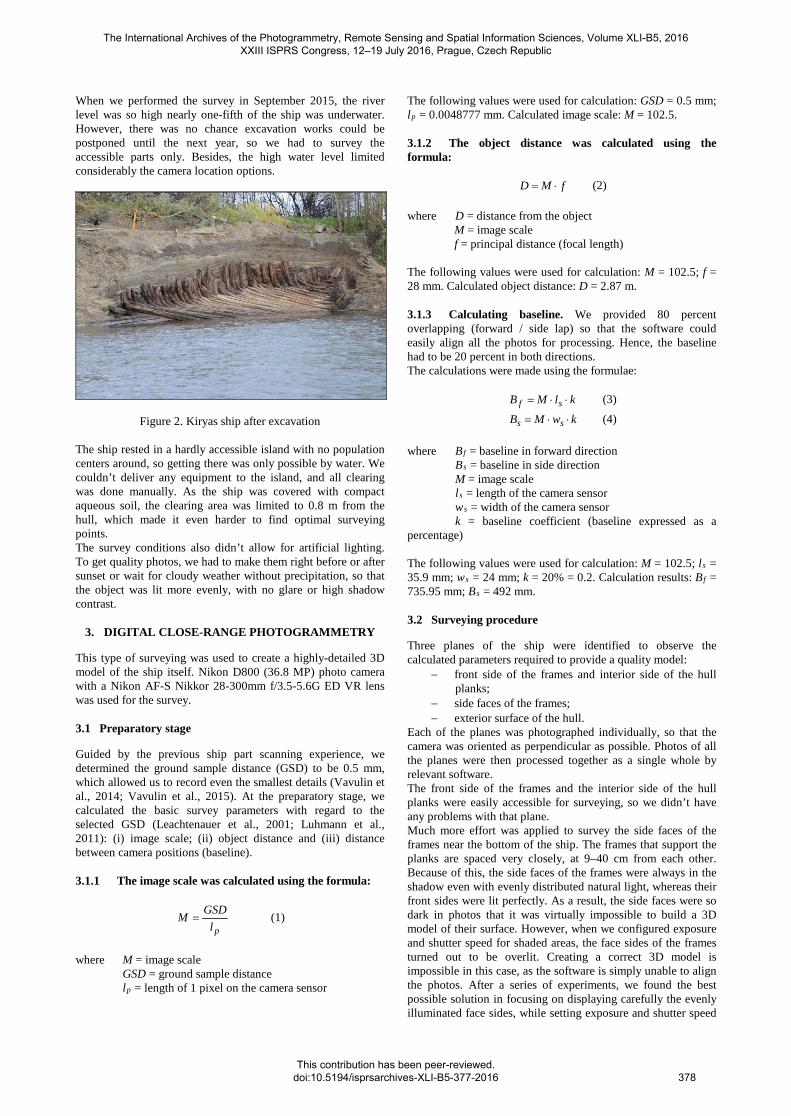
When we performed the survey in September 2015, the river level was so high nearly one-fifth of the ship was underwater. However, there was no chance excavation works could be postponed until the next year, so we had to survey the accessible parts only. Besides, the high water level limited considerably the camera location options.
Figure 2. Kiryas ship after excavation The ship rested in a hardly accessible island with no population centers around, so getting there was only possible by water. We couldn’t deliver any equipment to the island, and all clearing was done manually. As the ship was covered with compact aqueous soil, the clearing area was limited to 0.8 m from the hull, which made it even harder to find optimal surveying points. The survey conditions also didn’t allow for artificial lighting. To get quality photos, we had to make them right before or after sunset or wait for cloudy weather without precipitation, so that the object was lit more evenly, with no glare or high shadow contrast.
3. DIGITAL CLOSE-RANGE PHOTOGRAMMETRY
This type of surveying was used to create a highly-detailed 3D model of the ship itself. Nikon D800 (36.8 MP) photo camera with a Nikon AF-S Nikkor 28-300mm f/3.5-5.6G ED VR lens was used for the survey. 3.1 Preparatory stage
Guided by the previous ship part scanning experience, we determined the ground sample distance (GSD) to be 0.5 mm, which allowed us to record even the smallest details (Vavulin et al., 2014; Vavulin et al., 2015). At the preparatory stage, we calculated the basic survey parameters with regard to the selected GSD (Leachtenauer et al., 2001; Luhmann et al., 2011): (i) image scale; (ii) object distance and (iii) distance between camera positions (baseline). 3.1.1 The image scale was calculated using the formula:
plGSDM = (1)
where M = image scale GSD = ground sample distance lp = length of 1 pixel on the camera sensor
The following values were used for calculation: GSD = 0.5 mm; lp = 0.0048777 mm. Calculated image scale: M = 102.5. 3.1.2 The object distance was calculated using the formula:
fMD ⋅= (2)
where D = distance from the object M = image scale f = principal distance (focal length) The following values were used for calculation: M = 102.5; f = 28 mm. Calculated object distance: D = 2.87 m. 3.1.3 Calculating baseline. We provided 80 percent overlapping (forward / side lap) so that the software could easily align all the photos for processing. Hence, the baseline had to be 20 percent in both directions. The calculations were made using the formulae:
klMB sf ⋅⋅= (3)
kwMB ss ⋅⋅= (4)
where Bf = baseline in forward direction Bs = baseline in side direction M = image scale ls = length of the camera sensor ws = width of the camera sensor k = baseline coefficient (baseline expressed as a
percentage) The following values were used for calculation: M = 102.5; ls = 35.9 mm; ws = 24 mm; k = 20% = 0.2. Calculation results: Bf = 735.95 mm; Bs = 492 mm. 3.2 Surveying procedure
Three planes of the ship were identified to observe the calculated parameters required to provide a quality model:
− front side of the frames and interior side of the hull planks;
− side faces of the frames; − exterior surface of the hull.
Each of the planes was photographed individually, so that the camera was oriented as perpendicular as possible. Photos of all the planes were then processed together as a single whole by relevant software. The front side of the frames and the interior side of the hull planks were easily accessible for surveying, so we didn’t have any problems with that plane. Much more effort was applied to survey the side faces of the frames near the bottom of the ship. The frames that support the planks are spaced very closely, at 9–40 cm from each other. Because of this, the side faces of the frames were always in the shadow even with evenly distributed natural light, whereas their front sides were lit perfectly. As a result, the side faces were so dark in photos that it was virtually impossible to build a 3D model of their surface. However, when we configured exposure and shutter speed for shaded areas, the face sides of the frames turned out to be overlit. Creating a correct 3D model is impossible in this case, as the software is simply unable to align the photos. After a series of experiments, we found the best possible solution in focusing on displaying carefully the evenly illuminated face sides, while setting exposure and shutter speed
The International Archives of the Photogrammetry, Remote Sensing and Spatial Information Sciences, Volume XLI-B5, 2016 XXIII ISPRS Congress, 12–19 July 2016, Prague, Czech Republic
This contribution has been peer-reviewed. doi:10.5194/isprsarchives-XLI-B5-377-2016
378

to convey at least some texture of the shaded areas instead of leaving them totally blacked out. In this case, the software manages to align the photos successfully, at the same time being able to construct surfaces of the shaded areas. The biggest challenge, however, was surveying the exterior surface of the right side. This part of the ship had been buried under the scree of the bank and river sediments. After the ship was cleared, a 0.8 m trench was dug out along its right hull. It was technically impossible to widen this trench, so we could only take very large-scale photos at such a close distance even when we used the shortest focal length. As a solution to this problem, we made three series of shots from different angles to the hull: 70, 45 and 30 degrees. This provided us with detailed images shot almost perpendicular to the surface as well as overview photos (at 45 and 30 degrees), which, once processed, helped reduce errors in building the model geometry. Unfortunately, some of the parts came off during clearing owing to the damaged condition of the ship. That is why photos were taken prior to final documenting. First of all, the parts were photographed in situ to be associated with the basic model. Next, they were removed from the excavation site and photographed individually from all sides to be later integrated into the final model. When detailed images of each plane were made, we shot series of overview photos to improve camera network geometry. All in all, we made 3,123 photos which were used to build the 3D model. Eleven control points distributed on the surface of the ship were photographed for the purpose of georeferencing. The control points were read using Trimble M3 digital total station. 3.3 Software processing:
The survey data was processed using Agisoft Photoscan Professional software and a computer with the following specs: Intel Core i7-3960X 3.3GHz, 64GbRAM, nVidia Quadro 5000 2Gb (2 pcs), Microsoft Windows 8 64bit. Construction of 3D models included five steps: (i) estimating image quality; (ii) aligning photos; (iii) building a dense cloud; (iv) building mesh; (v) building texture. At the first stage (i), image quality was calculated automatically. Photoscan calculated quality parameters based on the level of sharpness in the most focused part of the picture. Images with quality value of less than 0.5 units were excluded from photogrammetric processing. Photo alignment (ii) was performed using the parameters of accuracy (medium) and pair preselection (generic). At this stage, the program calculated internal camera parameters and relative orientation of images. The result was a sparse point cloud representing the scene geometry (Fig. 3a). The process of photo alignment took 4 hours 20 minutes. The whole model was divided into nine units so that the computer could process the bulk of data obtained in the survey. At the stages that followed, each unit was processed individually. At the dense cloud building stage (iii), the program calculated depth information for each photo to be combined into a single dense point cloud (Fig. 3b). The high quality value was used to build a dense cloud, providing a model resolution of about 0.46 mm. Processing took approximately 72 hours for every chunk. At the mesh building stage (iv), the program connected points in the dense cloud to each other and formed the shape of a 3D model (Fig. 3c). Both types of recording used the “Face count – High” parameter to provide the maximum amount of detail in the model. The process of mesh building took about 1.5 hours for every chunk.
At the texture building stage (v), the program calculated texture atlas from the photos included in the project (Fig. 3d). 16000x16000 resolution texture mapping took about 3.5 hours for every chunk. As the 3D model was built, it had to be referenced to 11 GCP’s (ground control points). Positioning error was 3.6 cm on average.
Figure 3. Data processing stages
4. AERIAL PHOTOGRAPHY USING DIGITAL
PHOTOGRAMMETRY TECHNOLOGY
ZALA 421-22Ф UAV with a Sony RX1 camera was used to perform aerial photography of the ship location area. This type of surveying was used to create a 3D model of the ship discovery site. Site investigation was extremely important for finding out how the ship had got there. The space images of the discovery site available to us were of insufficient resolution. Such images could only give a general idea of the ship location,
The International Archives of the Photogrammetry, Remote Sensing and Spatial Information Sciences, Volume XLI-B5, 2016 XXIII ISPRS Congress, 12–19 July 2016, Prague, Czech Republic
This contribution has been peer-reviewed. doi:10.5194/isprsarchives-XLI-B5-377-2016
379

but the specifics of its position as to the bank line could not be seen. The flight was performed at an altitude of 100 m above the ground (Fig. 4). The choice of this height was based on flight safety, not on the selected resolution in this case. Consequently, photos were made with a very high resolution (GSD = 1.7 cm), forward lap and side lap being 75 and 70 percent, respectively. The survey field measured 766x193 m, the total area being 147,838 sq m. The survey produced 232 photos which were then processed with Agisoft Photoscan Professional software using the same algorithm as in terrestrial digital photogrammetry. As long as aerial photography resolution was much higher than required, we used the low quality value at the dense cloud building stage. Finally, we built a 3D model with 10 cm resolution displaying all necessary relief details. 16000x16000 texture was created for this model.
Figure 4. Flight structure. 232 images taken at 100m height
Aerial photography of the ship using a UAV at low altitude was additionally performed to increase accuracy of geometry of the 3D model constructed using terrestrial photogrammetry. Unfortunately, we only managed to do a large-scale survey at 25 m above the ship due to unfavorable flight conditions (abundance of trees and constant strong wind from the river). Nevertheless, the high resolution of the camera installed on the UAV allowed us to get high-quality photos of the ship with a resolution (GSD) of 4.25 mm. The photos were then aligned with the images obtained in the terrestrial survey and processed in Agisoft Photoscan.
5. RECONSTRUCTION OF THE MISSING SHIP ELEMENTS USING PHOTOS OF THE PREVIOUS
YEARS
As we mentioned above, the condition of the ship had been deteriorating from year to year since its discovery in 1997. The exposed front part got damaged the most. Five side frames and some hull planks went missing somewhere between examination of the ship in 2012 and our survey in 2015. However, the most significant loss was that of two fore frames with special vertical recesses on one side of each. The recesses were important structural elements, and their total loss would have definitely affected the accuracy of reconstruction. By fortunate coincidence, we got hold of a bunch of photos made in 2012 using a Canon EOS 1100D with 6.3 MP resolution. Originally, we only meant to use those photos in our illustrated report on the current condition of the ship but not for digital photogrammetry. Yet, the decent quality and the large variety of camera angles allowed us to create 3D models of the now missing ship elements. First of all, we selected photos shot from different angles with sufficient overlap to be aligned by Agisoft Photoscan. Next, the
photos were aligned in groups using the “Align chunks” procedure. A total of 30 photos were processed. Having grouped the photos back together, we performed processing using the algorithm employed in the terrestrial digital photogrammetry survey. We set the highest quality parameters possible at all stages (“Align photos – Highest”; “Build dense cloud – Ultra high”; “Face count – High”). As long as the ship was photographed unevenly, the quality of the model differs from part to part. Luckily enough, the part with the missing elements has been reproduced better than anything else (Fig. 5). The highest resolution in the model is 3 mm. Of course, the overall quality of the model is not perfect, but we managed to restore the general form and size of the currently missing elements. This 3D model will be later used for the ship reconstruction.
Figure 5. Reconstruction of the missing ship elements
6. USING 3D MODELS IN MUSEUM PRESENTATION
From the very beginning, the survey project implied subsequent restoration and exhibition of the ship in Shuvayev Nizhnevartovsk Museum of Local Core. In the future, the exhibit will also feature virtual digital 3D models of the ship. In the best-case scenario, restoration of the ship will be completed in 2020, being a laborious and time-consuming process. By then, a new museum building with a special pavilion for the ship is scheduled to have been constructed. However, the 2015 survey aroused enormous public interest, so the museum administrators decided to set up a temporary exhibition by June 2016 to present some of the artifacts ready for exhibiting. We provided the following materials for this project: (i) a 3D printed miniature of the ship and (ii) a stereo video showing a virtual flight around the ship at the discovery site. 6.1 3D printed miniature of the ship:
A 3D printed miniature of the ship was created for museum exhibition. Mcor Iris 3D printer providing good color texture was chosen to display the archaeologized remains of the ship and the immediate surroundings. This printer works by cutting slices of the 3D model from A4 paper sheets one by one while gluing them one on another. Color texture is provided by preliminary duplex printing of images on each sheet using
The International Archives of the Photogrammetry, Remote Sensing and Spatial Information Sciences, Volume XLI-B5, 2016 XXIII ISPRS Congress, 12–19 July 2016, Prague, Czech Republic
This contribution has been peer-reviewed. doi:10.5194/isprsarchives-XLI-B5-377-2016
380

Epson B-310N color inkjet printer. The technology allows printing a 260x170x150 mm model in a single print. The miniature was based on the model we had obtained surveying the ship with a UAV at an altitude of 25 m. The model resolution was high enough to produce a small-scale miniature of the ship and its close surroundings. Prior to printing, the model underwent some additional processing. First, it was decimated down to 4.5 mln polygons. Quite obviously, aerial photography could not provide accurate reconstruction of the water surface and the underwater part of the ship. With a view to make the surroundings look smoother and more real, we integrated a plane at the water level and projected a waterlike texture onto this plane. Next, the model was developed into a closed 3D structure with no boundaries or holes. Scale 1:70 was selected for printing. At this scale, the whole model can be printed in two prints with maximum fill percentage. It took 110 hours to print the final 500x162x95 mm miniature featuring 1,570 layers in two prints. 6.2 Video showing a virtual flight around the ship:
Video became another way of museum presentation for the ship (Fig. 6). Autodesk 3d Studio Max software was used for scene creation and rendering. Standard materials, cameras and lighting were used to set the scene. No extra visual effects were applied. The video was divided into four phases. Phase one is capturing a Google Earth animation. In the video, the camera is going from the planet scale down to the ship location, where large-scale aerial photography of the discovery site was carried out. This phase is necessary to indicate visually the geographical location of the ship’s remains.
Figure 6. Thumbnails of the video
In phase two, we demonstrate the 3D model of the surroundings obtained by means of large-scale aerial photography. A river simulation was added to improve the visual sequence. Matchmoving technology was used to provide a smooth transition between phases one and two (Autodesk MatchMover 2014 software). Phase three demonstrates the model constructed using photos made from a UAV at an altitude of 30 m.
Phase four shows the highest-resolution model. Each part of the exported model was decimated down to 1 mln polygons to be used in the video, yet maintaining the high texture resolution. The scene was designed so the video could be played in stereo. In order to create a stereo image, the scene was rendered from two cameras using the directional method and a script to automatically calculate and modify the stereo base depending on the distance between the camera plane and zero parallax. In this case, we used a simplified stereo base calculation formula:
LB ⋅= 02.0 (5)
where B = Stereo base L = Distance from camera plane to zero parallax.
The frames were visualized with 1920×1080 resolution and saved as PNG images with an alpha channel activated. All in all, 8,000 frames were created (4,000 with each camera), which were used to make a video with the help of Adobe Premiere Pro CS6. The frames were compressed twice in width and exposed side by side. The resulting video is 1080p/24fps with a duration of 2 minutes 47 seconds.
7. CONCLUSIONS
3D recording of the Ob ship at its discovery site has been successfully completed by now. We are coming to the long process of ship restoration and reassembly in Nizhnevartovsk Museum of Local Core. The 3D model we’ve created will serve a reliable basis for the ship reconstruction. This whole project is the very first experience in museumification of historic ships in Siberia.
ACKNOWLEDGEMENTS
This work was performed in the framework of the project “Man in a Changing World. Problems of Identity and Social Adaptation in History and at Present” (Russian Government Grant № 14.B25.31.0009).
REFERENCES
Leachtenauer J. C., Driggers R. G., 2001. Surveillance and Reconnaissance Imaging Systems: Modeling and Performance Prediction. Artech House, London pp. 25–32.
Luhmann T., Robson S., Kyle S., Harley I., 2011, Close Range Photogrammetry: Principles, Techniques and Applications, Whittles Publishing, UK. pp. 97-103.
Vavulin M., Zaitseva O., Pushkarev A., 2015. 3D digitizing of the naval details of a «Koch» (boat). Virtual Archaeology (methods and benefits). The State Hermitage Publishers, Saint Petersburg pp. 234-239.
Vavulin M.V., Zaytseva O.V., Pushkarev A.A., 2014. 3D scanning techniques and practices used for different types of archaeological artifacts. Siberian Historical Research, 4, pp. 21-37.
The International Archives of the Photogrammetry, Remote Sensing and Spatial Information Sciences, Volume XLI-B5, 2016 XXIII ISPRS Congress, 12–19 July 2016, Prague, Czech Republic
This contribution has been peer-reviewed. doi:10.5194/isprsarchives-XLI-B5-377-2016
381