3ek7 distribution class surge arresters
TRANSCRIPT

Answers for energy.
3EK7 Distribution Class Surge Arresters
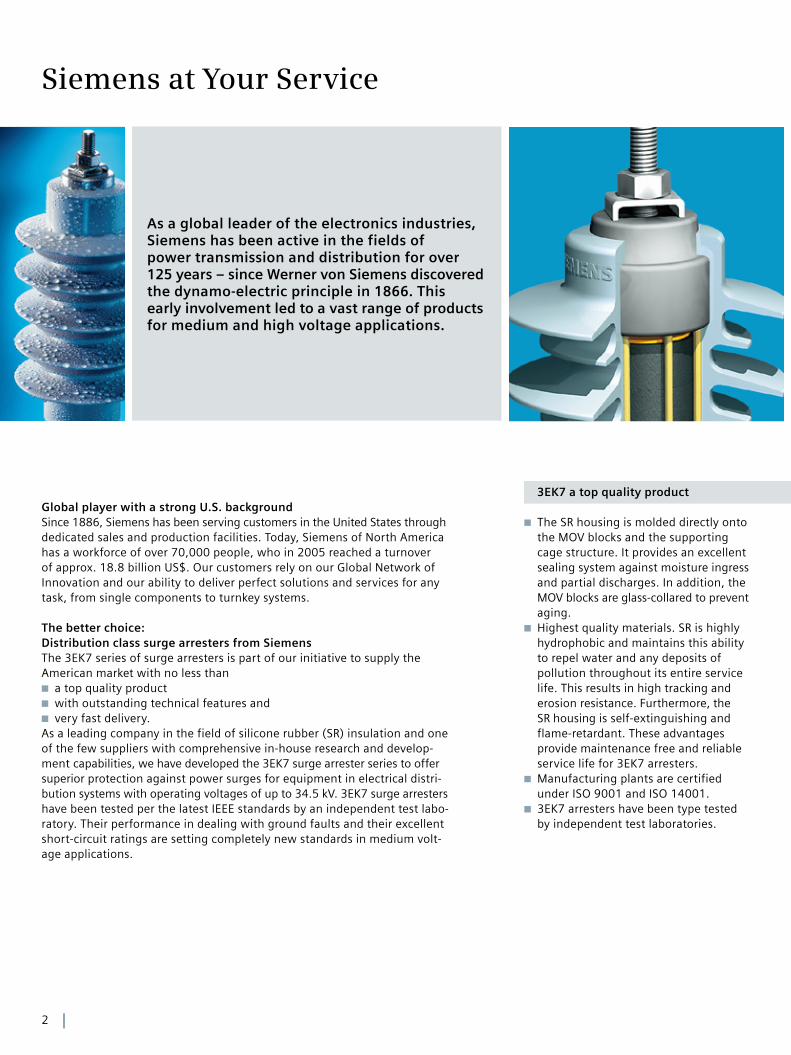
As a global leader of the electronics industries, Siemens has been active in the fields of power transmission and distribution for over 125 years – since Werner von Siemens discovered the dynamo-electric principle in 1866. This early involvement led to a vast range of products for medium and high voltage applications.
2
3EK7 a top quality productGlobal player with a strong U.S. backgroundSince 1886, Siemens has been serving customers in the United States through dedicated sales and production facilities. Today, Siemens of North America has a workforce of over 70,000 people, who in 2005 reached a turnover of approx. 18.8 billion US$. Our customers rely on our Global Network of Innovation and our ability to deliver perfect solutions and services for any task, from single components to turnkey systems.
The better choice: Distribution class surge arresters from SiemensThe 3EK7 series of surge arresters is part of our initiative to supply the American market with no less than
a top quality product ■
with outstanding technical features and ■
very fast delivery. ■
As a leading company in the field of silicone rubber (SR) insulation and one of the few suppliers with comprehensive in-house research and develop-ment capabilities, we have developed the 3EK7 surge arrester series to offer superior protection against power surges for equipment in electrical distri-bution systems with operating voltages of up to 34.5 kV. 3EK7 surge arresters have been tested per the latest IEEE standards by an independent test labo-ratory. Their performance in dealing with ground faults and their excellent short- circuit ratings are setting completely new standards in medium volt-age applications.
The SR housing is molded directly onto ■
the MOV blocks and the supporting cage structure. It provides an excellent sealing system against moisture ingress and partial discharges. In addition, the MOV blocks are glass-collared to prevent aging.Highest quality materials. SR is highly ■
hydrophobic and maintains this ability to repel water and any deposits of pollution throughout its entire service life. This results in high tracking and erosion resistance. Furthermore, the SR housing is self-extinguishing and flame-retardant. These advantages provide maintenance free and reliable service life for 3EK7 arresters.Manufacturing plants are certified ■
under ISO 9001 and ISO 14001. 3EK7 arresters have been type tested ■
by independent test laboratories.
Siemens at Your Service
3
The 3EK7 series is based on a cage of ■
pre-stressed fiber-glass rods for high mechanical strength. In the extremely rare event of the resistors being over-loaded, arcing cannot result in a build-up of critical internal pressure, since the resistors are not enclosed in a sealed mechanical shell. Thus, the arc can escape through the silicone sheath, leaving the mechanical support struc-ture of the enclosure unharmed, reducing the risk of internal compo-nents being ejected.The cage is lightweight design and yet ■
it offers excellent torsional, tensile and cantilever strength: Maximum working cantilever strength of 2400 in-lbf.SR is resistant to UV and ozone expo- ■
sure as well as to all common organic and non-organic solvents and cleaning agents. Therefore, the 3EK7 is suitable for any environmental condition of industrial areas as well as for desert or coastal regions.Temperature range – 55 °C to + 50 °C ■
Application altitude up to 12,000 ft. ■
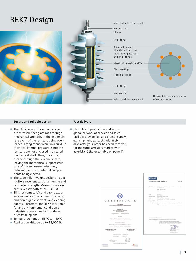
Horizontal cross section view of surge arrester
⅜ inch stainless steel stud
End fitting
Silicone housing,directly molded over MOV, fiber-glass rods and end fittings
Metal oxide varistor MOV
Fiber-glass rods
End fitting
⅜ inch stainless steel stud
ClampNut, washer
Nut, washer
Glass coating
3EK7 Design
Flexibility in production and in our ■
global network of service and sales facilities provide fast and prompt supply e.g. shipment ex stocks within six days after your order has been received for the surge arresters marked with asterisk (*) (Refer to table on page 4).
Secure and reliable design Fast delivery

Time in seconds
0.01 0.1 1 10 100 1000 10000
Voltage per unit MCOV
1.7
1.6
1.5
1.4
1.3
1.2
1.1
1.8
3EK7 heavy duty
3EK7 riser pole
4
Normal duty Heavy duty/Riser pole
Maximum continuous operating voltage MCOV
29 kV
Duty cycle voltage 36 kV
High current pressure relief 20 kA
Maximum design cantilever load-static (MDCL)
2400 inch-lbf
Coordinating current 5 kA 10 kA
Low-current, long-duration 75 A 250 A
High-current, short-duration 65 kA 100 kA
Energy absoption capability 2.7 kJ/kV MCOV 4.6 kJ/kV MCOV
Table 1: 3EK7 distribution arrester main data
System L-L voltage
[kV]
Four-wire multigrounded
neutral wye
Three-wire low impedance grounded
neutral circuit
Three-wire high impedance grounded
neutral circuit
2 .4 3EK7 030…
4 .16 3EK7 030… 3EK7 060… 3EK7 060…
4 .26 3EK7 060…
4 .8 3EK7 060…
6 .9 3EK7 090…
8 .3 3EK7 060… 3EK7 090…
12 3EK7 090… 3EK7 120…
12 .473EK7 090…
or 3EK7 100…
3EK7 150…
13 .2 3EK7 100… 3EK7 150…
13 .83EK7 100…
or 3EK7 120...
3EK7 150… 3EK7 180…
20 .78 3EK7 150… 3EK7 210…
22 .86 3EK7 150… 3EK7 210…
23 3EK7 300…
24 .94 3EK7 180… 3EK7 270…
27 .6 3EK7 210… 3EK7 300…
34 .5 3EK7 270… 3EK7 360…
Table 2: Typical 3EK7 arresters for system voltages according to the latest IEEE Std C 62.22
Table 3: Temporary overvoltage preheating to 60 °C, no prior duty
3EK7 Main Data and Selection
Electrical and Mechanical Data
Duty cycle MCOVArrester
part numberMaximum discharge voltage
Creepage distance
Flashover distance
LIWV3) Height„H“2)
Net weight
Packed1) weight
Standard1) pallet
weight
Qty. per pallet
[kV] [kV]
FOW 0.5 μs, 5 kA
[kV]
1.5 kA8/20 μs
[kV]
3 kA8/20 μs
[kV]
5 kA8/20 μs
[kV]
10 kA8/20 μs
[kV]
20 kA8/20 μs
[kV]
40 kA8/20 μs
[kV]
125 A30/60 μs
[kV]
500 A30/60 μs
[kV] [inch] [inch] [kV] [inch] [lbs] [lbs] [lbs] [pcs]
3 2 .55 3EK7 030 -2AB4 10 .0 8 .2 8 .6 9 .1 9 .9 11 .6 14 .0 6 .9 7 .4 14 .6 7 .1 94 6.7 3.1 4.3 960 216
6 5 .1 3EK7 060 -2AB4 20 .0 16 .3 17 .3 18 .2 19 .8 23 .3 28 .0 13 .8 14 .9 14 .6 7 .1 94 6.7 3.2 4.4 987 216
9 * 7 .65 3EK7 090 -2AB4 30 .0 24 .5 25 .9 27 .2 29 .7 34 .9 42 .0 20 .7 22 .3 14 .6 7 .1 94 6.7 3.3 4.5 1013 216
10 * 8 .4 3EK7 100 -2AB4 33 .3 27 .2 28 .8 30 .3 33 .0 38 .8 46 .6 24 .8 24 .8 14 .6 7 .1 94 6.7 3.4 4.6 1026 216
12 10 .2 3EK7 120 -2AC4 38 .8 31 .7 33 .5 35 .2 38 .4 45 .1 54 .3 26 .8 28 .9 19 .1 8 .3 109 7.9 3.9 5.1 1142 216
15 12 .7 3EK7 150 -2AC4 48 .4 39 .6 41 .8 44 .0 48 .0 56 .4 67 .8 33 .5 36 .1 19 .1 8 .3 109 7.9 4.1 5.3 1169 216
18 * 15 .3 3EK7 180 -2AD4 57 .2 46 .8 49 .4 52 .0 56 .7 66 .6 80 .1 39 .5 42 .7 23 .8 9 .8 129 9.4 4.8 6.0 1325 216
21 17 3EK7 210 -2AD4 66 .8 54 .6 57 .7 60 .7 66 .2 77 .7 93 .5 46 .1 49 .8 23 .8 9 .8 129 9.4 4.9 6.1 1352 216
24 19 .5 3EK7 240 -2AE4 73 .9 60 .4 63 .8 67 .2 73 .2 86 .0 103 51 .0 55 .1 30 .5 11 .3 149 10.6 5.6 7.2 1071 144
27 * 22 3EK7 270 -2AF4 83 .1 68 .0 71 .8 75 .6 82 .4 96 .7 116 57 .4 62 .0 35 .4 12 .5 165 11.8 6.3 8.0 1180 144
30 24 .4 3EK7 300 -2AF4 92 .3 75 .6 79 .7 83 .9 91 .5 107 129 63 .8 68 .8 35 .4 12 .5 165 11.8 6.4 8.0 1190 144
33 27 .5 3EK7 330 -2AH4 102 83 .1 87 .7 92 .3 101 118 142 70 .2 75 .7 48 .4 16 .5 217 15.7 8.1 9.7 969 96
36 29 3EK7 360 -2AH4 111 90 .7 95 .7 101 110 129 155 76 .6 82 .6 48 .4 16 .5 217 15.7 8.2 9.9 981 96
Table 4: 3EK7 normal duty
[kV] [kV]
FOW 0.5 μs, 5 kA
[kV]
1.5 kA8/20 μs
[kV]
3 kA8/20 μs
[kV]
5 kA8/20 μs
[kV]
10 kA8/20 μs
[kV]
20 kA8/20 μs
[kV]
40 kA8/20 μs
[kV]
125 A30/60 μs
[kV]
500 A30/60 μs
[kV] [inch] [inch] [kV] [inch] [lbs] [lbs] [lbs] [pcs]
3 * 2 .55 3EK7 030 -3AB4 10 .5 8 .0 8 .4 8 .8 9 .5 10 .9 12 .6 6 .7 7 .2 14 .6 7 .1 94 6 .7 3 .2 4 .4 991 216
6 * 5 .1 3EK7 060 -3AB4 21 .6 16 .5 17 .2 18 .2 19 .6 22 .5 26 .1 13 .9 14 .9 14 .6 7 .1 94 6 .7 3 .5 4 .7 1042 216
9 * 7 .65 3EK7 090 -3AB4 30 .9 23 .6 24 .7 26 .1 28 .1 32 .3 37 .4 20 .0 21 .4 14 .6 7 .1 94 6 .7 3 .7 4 .9 1084 216
10 * 8 .4 3EK7 100 -3AB4 32 .3 24 .7 25 .9 27 .3 29 .4 33 .8 39 .1 20 .9 22 .3 14 .6 7 .1 94 6 .7 3 .7 4 .9 1091 216
12 10 .2 3EK7 120 -3AC4 41 .0 31 .3 32 .8 34 .7 37 .3 42 .9 49 .6 26 .5 28 .3 19 .1 8 .3 109 7 .9 4 .3 5 .5 1229 216
15 * 12 .7 3EK7 150 -3AD4 51 .3 39 .1 41 .0 43 .3 46 .6 53 .6 62 .0 33 .1 35 .4 23 .8 9 .8 129 9 .4 5 .2 6 .4 1410 216
18 * 15 .3 3EK7 180 -3AD4 61 .5 47 .0 49 .2 52 .0 55 .9 64 .3 74 .3 39 .7 42 .5 23 .8 9 .8 129 9 .4 5 .4 6 .6 1458 216
21 * 17 3EK7 210 -3AE4 67 .3 51 .4 53 .9 56 .9 61 .2 70 .4 81 .4 43 .5 46 .5 30 .5 11 .3 149 10 .6 6 .1 7 .3 1083 144
24 19 .5 3EK7 240 -3AF4 77 .6 59 .2 62 .0 65 .6 70 .5 81 .1 93 .8 50 .1 53 .6 35 .4 12 .5 165 11 .8 6 .9 8 .5 1260 144
27 * 22 3EK7 270 -3AF4 87 .7 66 .9 70 .1 74 .1 79 .7 91 .7 106 56 .6 60 .6 35 .4 12 .5 165 11 .8 7 .1 8 .7 1292 144
30 * 24 .4 3EK7 300 -3AH4 96 .6 73 .8 77 .3 81 .7 87 .8 101 117 62 .3 66 .7 48 .4 16 .5 217 15 .7 8 .9 10 .6 1048 96
33 27 .5 3EK7 330 -3AH4 108 82 .7 86 .6 91 .5 98 .4 113 131 69 .9 74 .8 48 .4 16 .5 217 15 .7 9 .1 10 .8 1071 96
36 29 3EK7 360 -3AH4 119 90 .6 94 .9 100 108 124 143 76 .5 81 .9 48 .4 16 .5 217 15 .7 9 .3 11 .0 1090 96
Table 5: 3EK7 heavy duty
[kV] [kV]
FOW 0.5 μs, 5 kA
[kV]
1.5 kA8/20 μs
[kV]
3 kA8/20 μs
[kV]
5 kA8/20 μs
[kV]
10 kA8/20 μs
[kV]
20 kA8/20 μs
[kV]
40 kA8/20 μs
[kV]
125 A30/60 μs
[kV]
500 A30/60 μs
[kV] [inch] [inch] [kV] [inch] [lbs] [lbs] [lbs] [pcs]
3 2 .55 3EK7 030 -4AB4 8 .9 6 .8 7 .1 7 .5 8 .1 9 .3 10 .8 5 .8 6 .2 14 .6 7 .1 94 6 .7 3 .2 4 .4 982 216
6 5 .1 3EK7 060 -4AB4 17 .7 13 .5 14 .2 15 .0 16 .1 18 .5 21 .4 11 .4 12 .2 14 .6 7 .1 94 6 .7 3 .4 4 .6 1026 216
9 * 7 .65 3EK7 090 -4AB4 26 .4 20 .2 21 .1 22 .3 24 .0 27 .6 31 .9 17 .0 18 .2 14 .6 7 .1 94 6 .7 3 .5 4 .7 1047 216
10 * 8 .4 3EK7 100 -4AC4 29 .3 22 .3 23 .4 24 .7 26 .6 30 .6 35 .4 18 .9 20 .2 19 .1 8 .3 109 7 .9 4 .1 5 .3 1177 216
12 10 .2 3EK7 120 -4AD4 35 .2 26 .9 28 .2 29 .8 32 .0 36 .8 42 .6 22 .7 24 .3 23 .8 9 .8 129 9 .4 4 .9 6 .1 1350 216
15 12 .7 3EK7 150 -4AD4 43 .9 33 .5 35 .1 37 .1 39 .9 45 .9 53 .1 28 .3 30 .3 23 .8 9 .8 129 9 .4 5 .1 6 .2 1371 216
18 * 15 .3 3EK7 180 -4AE4 52 .7 40 .2 42 .2 44 .5 47 .9 55 .1 63 .7 34 .0 36 .4 30 .5 11 .3 149 10 .6 5 .8 7 .1 1054 144
21 17 3EK7 210 -4AF4 61 .5 47 .0 49 .2 52 .0 55 .9 64 .3 74 .3 39 .7 42 .5 35 .4 12 .5 165 11 .8 6 .5 7 .8 1154 144
24 19 .5 3EK7 240 -4AH4 70 .2 53 .6 56 .1 59 .3 63 .8 73 .4 84 .9 45 .3 48 .5 48 .4 16 .5 217 15 .7 8 .4 10 .1 1000 96
27 * 22 3EK7 270 -4AH4 79 .1 60 .4 63 .3 66 .9 71 .9 82 .7 95 .6 51 .0 54 .6 48 .4 16 .5 217 15 .7 8 .5 10 .2 1010 96
30 24 .4 3EK7 300 -4AH4 87 .7 66 .9 70 .1 74 .1 79 .7 91 .7 106 56 .6 60 .6 48 .4 16 .5 217 15 .7 8 .7 10 .4 1029 96
33 27 .5 3EK7 330 -4AK4 96 .6 73 .8 77 .3 81 .7 87 .8 101 117 62 .3 66 .7 62 .8 20 .5 270 20 .1 10 .7 12 .4 1221 96
36 29 3EK7 360 -4AK4 105 80 .5 84 .3 89 .1 95 .8 110 127 68 .0 72 .8 62 .8 20 .5 270 20 .1 10 .9 12 .6 1240 96
Table 6: 3EK7 riser pole

5
Duty cycle MCOVArrester
part numberMaximum discharge voltage
Creepage distance
Flashover distance
LIWV3) Height„H“2)
Net weight
Packed1) weight
Standard1) pallet
weight
Qty. per pallet
[kV] [kV]
FOW 0.5 μs, 5 kA
[kV]
1.5 kA8/20 μs
[kV]
3 kA8/20 μs
[kV]
5 kA8/20 μs
[kV]
10 kA8/20 μs
[kV]
20 kA8/20 μs
[kV]
40 kA8/20 μs
[kV]
125 A30/60 μs
[kV]
500 A30/60 μs
[kV] [inch] [inch] [kV] [inch] [lbs] [lbs] [lbs] [pcs]
3 2 .55 3EK7 030 -2AB4 10 .0 8 .2 8 .6 9 .1 9 .9 11 .6 14 .0 6 .9 7 .4 14 .6 7 .1 94 6.7 3.1 4.3 960 216
6 5 .1 3EK7 060 -2AB4 20 .0 16 .3 17 .3 18 .2 19 .8 23 .3 28 .0 13 .8 14 .9 14 .6 7 .1 94 6.7 3.2 4.4 987 216
9 * 7 .65 3EK7 090 -2AB4 30 .0 24 .5 25 .9 27 .2 29 .7 34 .9 42 .0 20 .7 22 .3 14 .6 7 .1 94 6.7 3.3 4.5 1013 216
10 * 8 .4 3EK7 100 -2AB4 33 .3 27 .2 28 .8 30 .3 33 .0 38 .8 46 .6 24 .8 24 .8 14 .6 7 .1 94 6.7 3.4 4.6 1026 216
12 10 .2 3EK7 120 -2AC4 38 .8 31 .7 33 .5 35 .2 38 .4 45 .1 54 .3 26 .8 28 .9 19 .1 8 .3 109 7.9 3.9 5.1 1142 216
15 12 .7 3EK7 150 -2AC4 48 .4 39 .6 41 .8 44 .0 48 .0 56 .4 67 .8 33 .5 36 .1 19 .1 8 .3 109 7.9 4.1 5.3 1169 216
18 * 15 .3 3EK7 180 -2AD4 57 .2 46 .8 49 .4 52 .0 56 .7 66 .6 80 .1 39 .5 42 .7 23 .8 9 .8 129 9.4 4.8 6.0 1325 216
21 17 3EK7 210 -2AD4 66 .8 54 .6 57 .7 60 .7 66 .2 77 .7 93 .5 46 .1 49 .8 23 .8 9 .8 129 9.4 4.9 6.1 1352 216
24 19 .5 3EK7 240 -2AE4 73 .9 60 .4 63 .8 67 .2 73 .2 86 .0 103 51 .0 55 .1 30 .5 11 .3 149 10.6 5.6 7.2 1071 144
27 * 22 3EK7 270 -2AF4 83 .1 68 .0 71 .8 75 .6 82 .4 96 .7 116 57 .4 62 .0 35 .4 12 .5 165 11.8 6.3 8.0 1180 144
30 24 .4 3EK7 300 -2AF4 92 .3 75 .6 79 .7 83 .9 91 .5 107 129 63 .8 68 .8 35 .4 12 .5 165 11.8 6.4 8.0 1190 144
33 27 .5 3EK7 330 -2AH4 102 83 .1 87 .7 92 .3 101 118 142 70 .2 75 .7 48 .4 16 .5 217 15.7 8.1 9.7 969 96
36 29 3EK7 360 -2AH4 111 90 .7 95 .7 101 110 129 155 76 .6 82 .6 48 .4 16 .5 217 15.7 8.2 9.9 981 96
[kV] [kV]
FOW 0.5 μs, 5 kA
[kV]
1.5 kA8/20 μs
[kV]
3 kA8/20 μs
[kV]
5 kA8/20 μs
[kV]
10 kA8/20 μs
[kV]
20 kA8/20 μs
[kV]
40 kA8/20 μs
[kV]
125 A30/60 μs
[kV]
500 A30/60 μs
[kV] [inch] [inch] [kV] [inch] [lbs] [lbs] [lbs] [pcs]
3 * 2 .55 3EK7 030 -3AB4 10 .5 8 .0 8 .4 8 .8 9 .5 10 .9 12 .6 6 .7 7 .2 14 .6 7 .1 94 6 .7 3 .2 4 .4 991 216
6 * 5 .1 3EK7 060 -3AB4 21 .6 16 .5 17 .2 18 .2 19 .6 22 .5 26 .1 13 .9 14 .9 14 .6 7 .1 94 6 .7 3 .5 4 .7 1042 216
9 * 7 .65 3EK7 090 -3AB4 30 .9 23 .6 24 .7 26 .1 28 .1 32 .3 37 .4 20 .0 21 .4 14 .6 7 .1 94 6 .7 3 .7 4 .9 1084 216
10 * 8 .4 3EK7 100 -3AB4 32 .3 24 .7 25 .9 27 .3 29 .4 33 .8 39 .1 20 .9 22 .3 14 .6 7 .1 94 6 .7 3 .7 4 .9 1091 216
12 10 .2 3EK7 120 -3AC4 41 .0 31 .3 32 .8 34 .7 37 .3 42 .9 49 .6 26 .5 28 .3 19 .1 8 .3 109 7 .9 4 .3 5 .5 1229 216
15 * 12 .7 3EK7 150 -3AD4 51 .3 39 .1 41 .0 43 .3 46 .6 53 .6 62 .0 33 .1 35 .4 23 .8 9 .8 129 9 .4 5 .2 6 .4 1410 216
18 * 15 .3 3EK7 180 -3AD4 61 .5 47 .0 49 .2 52 .0 55 .9 64 .3 74 .3 39 .7 42 .5 23 .8 9 .8 129 9 .4 5 .4 6 .6 1458 216
21 * 17 3EK7 210 -3AE4 67 .3 51 .4 53 .9 56 .9 61 .2 70 .4 81 .4 43 .5 46 .5 30 .5 11 .3 149 10 .6 6 .1 7 .3 1083 144
24 19 .5 3EK7 240 -3AF4 77 .6 59 .2 62 .0 65 .6 70 .5 81 .1 93 .8 50 .1 53 .6 35 .4 12 .5 165 11 .8 6 .9 8 .5 1260 144
27 * 22 3EK7 270 -3AF4 87 .7 66 .9 70 .1 74 .1 79 .7 91 .7 106 56 .6 60 .6 35 .4 12 .5 165 11 .8 7 .1 8 .7 1292 144
30 * 24 .4 3EK7 300 -3AH4 96 .6 73 .8 77 .3 81 .7 87 .8 101 117 62 .3 66 .7 48 .4 16 .5 217 15 .7 8 .9 10 .6 1048 96
33 27 .5 3EK7 330 -3AH4 108 82 .7 86 .6 91 .5 98 .4 113 131 69 .9 74 .8 48 .4 16 .5 217 15 .7 9 .1 10 .8 1071 96
36 29 3EK7 360 -3AH4 119 90 .6 94 .9 100 108 124 143 76 .5 81 .9 48 .4 16 .5 217 15 .7 9 .3 11 .0 1090 96
[kV] [kV]
FOW 0.5 μs, 5 kA
[kV]
1.5 kA8/20 μs
[kV]
3 kA8/20 μs
[kV]
5 kA8/20 μs
[kV]
10 kA8/20 μs
[kV]
20 kA8/20 μs
[kV]
40 kA8/20 μs
[kV]
125 A30/60 μs
[kV]
500 A30/60 μs
[kV] [inch] [inch] [kV] [inch] [lbs] [lbs] [lbs] [pcs]
3 2 .55 3EK7 030 -4AB4 8 .9 6 .8 7 .1 7 .5 8 .1 9 .3 10 .8 5 .8 6 .2 14 .6 7 .1 94 6 .7 3 .2 4 .4 982 216
6 5 .1 3EK7 060 -4AB4 17 .7 13 .5 14 .2 15 .0 16 .1 18 .5 21 .4 11 .4 12 .2 14 .6 7 .1 94 6 .7 3 .4 4 .6 1026 216
9 * 7 .65 3EK7 090 -4AB4 26 .4 20 .2 21 .1 22 .3 24 .0 27 .6 31 .9 17 .0 18 .2 14 .6 7 .1 94 6 .7 3 .5 4 .7 1047 216
10 * 8 .4 3EK7 100 -4AC4 29 .3 22 .3 23 .4 24 .7 26 .6 30 .6 35 .4 18 .9 20 .2 19 .1 8 .3 109 7 .9 4 .1 5 .3 1177 216
12 10 .2 3EK7 120 -4AD4 35 .2 26 .9 28 .2 29 .8 32 .0 36 .8 42 .6 22 .7 24 .3 23 .8 9 .8 129 9 .4 4 .9 6 .1 1350 216
15 12 .7 3EK7 150 -4AD4 43 .9 33 .5 35 .1 37 .1 39 .9 45 .9 53 .1 28 .3 30 .3 23 .8 9 .8 129 9 .4 5 .1 6 .2 1371 216
18 * 15 .3 3EK7 180 -4AE4 52 .7 40 .2 42 .2 44 .5 47 .9 55 .1 63 .7 34 .0 36 .4 30 .5 11 .3 149 10 .6 5 .8 7 .1 1054 144
21 17 3EK7 210 -4AF4 61 .5 47 .0 49 .2 52 .0 55 .9 64 .3 74 .3 39 .7 42 .5 35 .4 12 .5 165 11 .8 6 .5 7 .8 1154 144
24 19 .5 3EK7 240 -4AH4 70 .2 53 .6 56 .1 59 .3 63 .8 73 .4 84 .9 45 .3 48 .5 48 .4 16 .5 217 15 .7 8 .4 10 .1 1000 96
27 * 22 3EK7 270 -4AH4 79 .1 60 .4 63 .3 66 .9 71 .9 82 .7 95 .6 51 .0 54 .6 48 .4 16 .5 217 15 .7 8 .5 10 .2 1010 96
30 24 .4 3EK7 300 -4AH4 87 .7 66 .9 70 .1 74 .1 79 .7 91 .7 106 56 .6 60 .6 48 .4 16 .5 217 15 .7 8 .7 10 .4 1029 96
33 27 .5 3EK7 330 -4AK4 96 .6 73 .8 77 .3 81 .7 87 .8 101 117 62 .3 66 .7 62 .8 20 .5 270 20 .1 10 .7 12 .4 1221 96
36 29 3EK7 360 -4AK4 105 80 .5 84 .3 89 .1 95 .8 110 127 68 .0 72 .8 62 .8 20 .5 270 20 .1 10 .9 12 .6 1240 96
1) Incl. insulating bracket and disconnector, other accessory weights to be added (see next page); 2) Refer to figure 1 on page 6; 3) LIWV: Lightning impulse withstand voltage of the arrester housing ; (*) Available ex stock

Outline drawings for common design options are shown in figures 2, 3 and 4
6
Accessories
Figure 1: 3EK7 main dimensions; *see tables page 5
Figure 5: Disconnector (order code P31); 0.3 lbs
Figure 2: 3EK7 surge arrester with accessories P12 and P31
Figure 4: 3EK7 surge arrester with accessories P12, P31, P52 and Q11
Figure 3: 3EK7 surge arrester withaccessories P12, P31 and Q51
Figure 6: Insulating bracket for duty cycle 3 kV to 21 kV (order code P12); 0.5 lbs
Figure 7: Insulating bracket for duty cycle 24 kV and above (order code P12); 0.9 lbs
3/8”
Ø 4.7”
1.4
”
H*
3/8
”
0.95”
2.5
”1
.25
”0
.9”
1.1
”
1.3
”0
.6”
1.6
”
3”
6.7”4.9”1” 0.8”
Ø 0.56”
2.5
”1
.25
”0
.9”
1.1
”
1.3
”0
.6”
1.6
”3
”
10”8.3”1” 0.8”
Ø 0.56”

32
43
0(1
5)
(87
)
26
0
20
0
260
Ø ø200
30 60
M12
33
(3)
11
22+1
8
10
ø10,2
10
#11 AWG to #6 AWG
#6 AWG to #5 AWG
7
Figure 8: Transformer bracket 8.7 inches (order code Q11); 0.6 lbs Figure 9: Transformer bracket 11 inches (order code Q12); 1.8 lbs
Figure 11: Transformer bracket 14.5 inches (order code Q14); 2.0 lbsFigure 10: Transformer bracket 12.25 inches (order code Q13); 2.0 lbs
Figure 13: NEMA metal bracket (order code P11); 1.3 lbsFigure 12: NEMA X-arm bracket (order code Q51); 2.9 lbs
Figure 17: Bird protection cap(order code M81); 0.1 lbs
Figure 18: Line clamp (order code M11); 0.2 lbs
Figure 16: Insulated ground lead/Insulated line lead(order code P51/M51); 0.2 lbs
Figure 15: Ground strap for duty cycle 24 kV and above (order code P53); 0.2 lbs
Figure 14: Ground strap for duty cycle 3 kV to 21 kV(order code P52); 0.13 lbs
2.4
”
8.7”0.3”
0
.56
”
1”
1.6” 2.5”2.25”
1.6
”
0.8
”
0.5
6”
2.4
”
11” 0.3”
0
.56
”
1”1.6” 2.5”
2.25”
1.6
”
0.8
”
0.5
6”
1.6” 2.5”2.25”
1.6
”
0.8
”
0.5
6”
0
.56
”
2.4
”
0.3”
1”
12.25” 14.5”
2.4
” 0
.56
”
1.4
”
1.6
”
0.8
”
0.5
6” 2.7” 2.1”
1.8” 3.4” 2.5” 3.4”
0.3”
2.6
”2
.8”
8.6
”
7.8
”
4.1
”…5
.9”
1.8
”
2.9”0…4.75”
3.6”0.7”
Ø 0.7”
0.6
”
Ø 0.56”
2”
1”
6”
8”
Ø 0.4”
5 x 45° 5 x 45°
Ø 0.4
”
Ø 0.5
6”0.5”
12”13”
1”
5 x 45° 5 x 45°
Ø 0.4
”
Ø 0.5
6”0.5”
18”19”
1”
Ø 0.4
” Ø 0.51”
18”
Ø 0.6”
1”
2.2
5”
Ø 3”
0.04”
0.4” #11 AWG to #6 AWG
#6 AWG to #5 AWG

Part number 3 E K 7 210 – 3 A E 4
Internal use 3 E K 7Duty cycle voltage in kV x 10 210– –ClassificationDistribution class, normal duty 2Distribution class, heavy duty 3Riser pole 4StandardIEEE C62.11 with imperial-thread terminals 3/8" AIEEE C62.11 with metric-thread terminals M12 BIEC-CEI 60099-4 with metric-thread terminals M12 CHousing size6.7 inch B7.9 inch C9.4 inch D10.6 inch E11.8 inch F15.7 inch H20.1 inch KFor internal administrative purpose 4
Standard equipped withhigh voltage terminal with ■ 3/8 inch stud, clamp, washer and nutground terminal with ■ 3/8 inch stud, washer and nut
Part number with mounting accessories 3 E K 7 210 – 3 A E 4 – Z M51 M81 P12 P31 Q11
If any accessory is required* ZHigh-voltage terminal equipped withLine clamp, washer, nut M11Insulated line lead, 18 inch M51Bird protection cap M81Earth terminal equipped withNEMA metal bracket (hot dip galvanized steel) P11NEMA insulating bracket P12Disconnector P31Insulated ground lead, 18 inch P51Ground strap, 12 inch P52Ground strap, 18 inch P53Mounting auxiliariesTransformer bracket 8.7 inch Q11Transformer bracket 11 inch Q12Transformer bracket 12.25 inch Q13Transformer bracket 14.5 inch Q14NEMA X-arm bracket Q51
*Other additional parts on request.
Example
Example
Published by and copyright © 2010:Siemens AGEnergy SectorFreyeslebenstrasse 191058 Erlangen, Germany
Siemens Energy, Inc.Power Transmission Division444 Highway 49 SouthRichland, MS 39218Toll-free: +1 (800) 347-6659Phone: +1 (601) 932-9800Fax: +1 (601) 932-9911www.usa.siemens.com/energy www.siemens.com/energy/arrester-download
www.siemens.com/energy
Power Transmission Division Order No. E50001-F630-A126-X-4AUSPrinted in GermanyTH 263-101145 PA 11100.5
Printed on elementary chlorine-free bleached paper.
All rights reserved.Trademarks mentioned in this document are the property of Siemens AG, its affili-ates, or their respective owners.
Subject to change without prior notice.The information in this document con-tains general descriptions of the technical options available, which may not apply in all cases. The required technical options should therefore be specified in the contract.