3g catalog
DESCRIPTION
3G racks are the third generation of AMCO's adaptive enclosures for IT environments. They are available in heights of 42RU, 44RU and 47RU, panel widths of 19" and 24", and depths of 42", 45" and 48". The 3G can be ordered with or without full-length power panels for 0RU, tool-less power strip mounting and cable management. Racks are available in your choice of 10 standard durable powder coat color finishes.TRANSCRIPT

ENCLOSURE SYSTEMSThe Next Generation of Adaptive Enclosures for IT Environments
ENGINEERED PRODUCTS, LLC
TM
CAT3G1.1
CABLING
POWER
COOLING
CABLE
MA
NA
GE
ME
NT
FRAME

2
IMS ENGINEERED PRODUCTSNEW DATA SERVER SERIES
3G FeaturesOur Third Generation Server Cabinets have been designed and de-veloped thru years of experience in the IT sector and feedback fromreal world applications. This section highlights the standard featuresthat make this system adaptive to your specific IT environment andapplications. The flexibility to adjust future demands is evident inthe review of the internal and external components that define thisenclosure system.
Visit us on line at www.imsep.com for the latest updates andproduct releases. Use our Product Configurator to build aconsole in real-time. Get a drawing, BOM and 3D Model tosupport your exact design configuration.
04
Pre-ConfiguredOur Pre-Configured Series offers a selection of the most requestedconsoles that include frame, mounting channels, power panels, solidtop panel, beveled screened front door, French screened rear door,levelers and hardware kit. Pre-configured consoles are availablewith or without side panels. Technical support for consoles is locatedon pages 18 and 19 of this catalog.
08 CoolingThis section addresses the IMS approach to Cooling – basedon current trends in High Density Packaging and increasedthermal loads. We provide specific thermal solutions for re-quirements of 7.5kW and up. Can provide solutions for yourspecific thermal requirements - standard or custom.
17
PowerChoose from our specific group of power components that ad-dress today’s demands for power distribution, environmentaland power monitoring - in both horizontal and vertical config-urations. Twenty and thirty amp strips in 125v and 250v – witha variety of receptacle and plug models to choose from. UPSsystems are also available. Consoles can ship with power andUPS systems mounted to your specified location.
14
Build Your OwnSometimes pre-configured consoles can’t meet your SPECIFIC de-sign requirements. This section lists all of the standard componentsto build a console to your exact enclosure specifications. It also fea-tures accessories and additional components for the pre-configuredconsoles. This section also includes material gauge specificationsfor all 3G standard components. Technical support for componentsis located on pages 18 and 19 of this catalog.
10
On-Line Catalog& Product Configurator
IMS Engineered Products reserves the right to update/change products and make corrections without prior notice.
3
3G SERIES – ADAPTIVE ENCLOSURES
FOR IT ENVIRONMENTS
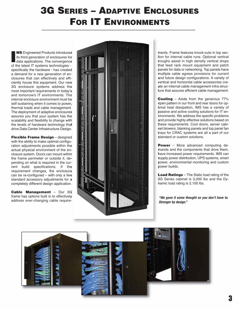
IMS Engineered Products introducesits third generation of enclosures fordata applications. The convergence
of the latest IT systems technologies –specifically the hardware - has createda demand for a new generation of en-closures that can effectively and effi-ciently house this equipment. Our new3G enclosure systems address themost important requirements in today’sand tomorrow's IT environments. Theinternal enclosure environment must beself sustaining when it comes to power,thermal loads and cable management.The deployment of adaptive enclosuresassures you that your system has thescalability and flexibility to change withthe levels of hardware technology thatdrive Data Center Infrastructure Design.
Flexible Frame Design – designedwith the ability to make optimal configu-ration adjustments possible within theactual physical environment of the en-closure system. Doors can mount withinthe frame perimeter or outside it, de-pending on what is required in the cur-rent build specifications. If therequirement changes, the enclosurecan be re-configured – with only a fewstandard accessory adjustments for acompletely different design application.
Cable Management – Our 3Gframe has options built in to effectivelyaddress ever-changing cable require-
ments. Frame features knock-outs in top sec-tion for internal cable runs. Optional verticaltroughs assist in high density vertical dropsthat feed rack mount equipment and patchpanels for data or networking. Top panels havemultiple cable egress provisions for currentand future design configurations. A variety ofvertical and horizontal cable accessories cre-ate an internal cable management infra-struc-ture that assures efficient cable management.
Cooling – Aside from the generous 77%open pattern in our front and rear doors for op-timal heat dissipation, IMS has a variety ofpassive and active cooling solutions for IT en-vironments. We address the specific problemsand provide highly effective solutions based onthese requirements. Cool doors, server cabi-net blowers, blanking panels and top panel fantrays for CRAC systems are all a part of ourstandard or custom solutions.
Power – More advanced computing de-mands and the components that drive them,have increased power requirements. IMS cansupply power distribution, UPS systems, smartpower, environmental monitoring and custompower builds.
Load Ratings – The Static load rating of the3G Series cabinet is 3,200 lbs and the Dy-namic load rating is 2,100 lbs.
“We gave it some thought so you don’t have to.Stronger by design.”
4
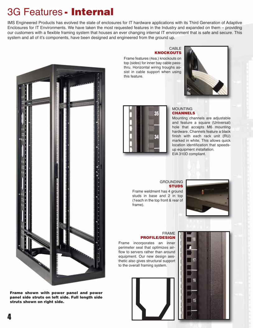
3G Features - Internal
CABLEKNOCKOUTS
Frame features (4ea.) knockouts ontop (sides) for inner bay cable pass-thru. Horizontal wiring troughs as-sist in cable support when usingthis feature.
GROUNDINGSTUDS
Frame weldment has 4 groundstuds in base and 2 in top(1each in the top front & rear offrame).
FRAMEPROFILE/DESIGN
Frame incorporates an innerperimeter seal that optimizes air-flow to servers rather than aroundequipment. Our new design aes-thetic also gives structural supportto the overall framing system.
MOUNTINGCHANNELSMounting channels are adjustableand feature a square (Universal)hole that accepts M6 mountinghardware. Channels feature a blackfinish with each rack unit (RU)marked in white. This allows quicklocation identification that speeds-up equipment installation.EIA 310D compliant.
IMS Engineered Products has evolved the state of enclosures for IT hardware applications with its Third Generation of AdaptiveEnclosures for IT Environments. We have taken the most requested features in the Industry and expanded on them – providingour customers with a flexible framing system that houses an ever changing internal IT environment that is safe and secure. Thissystem and all of it’s components, have been designed and engineered from the ground up.
Frame shown with power panel and powerpanel side struts on left side. Full length sidestruts shown on right side.
5
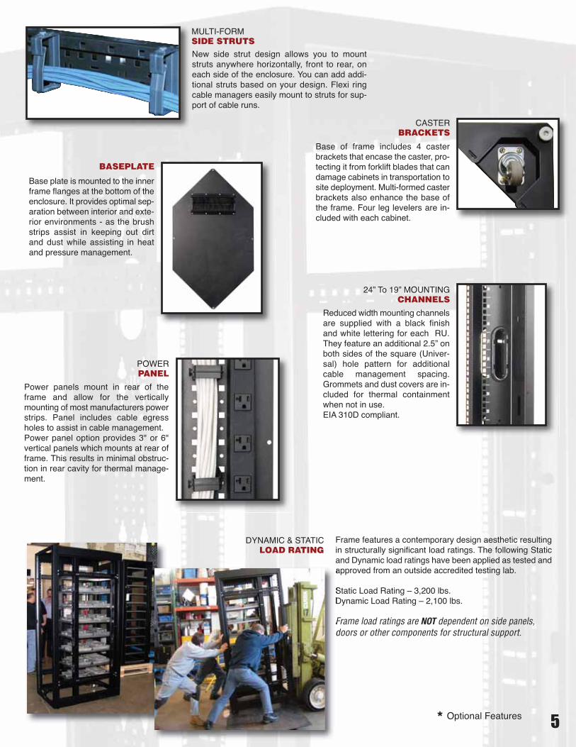
DYNAMIC & STATICLOAD RATING
POWERPANEL
Power panels mount in rear of theframe and allow for the verticallymounting of most manufacturers powerstrips. Panel includes cable egressholes to assist in cable management.Power panel option provides 3" or 6"vertical panels which mounts at rear offrame. This results in minimal obstruc-tion in rear cavity for thermal manage-ment.
MULTI-FORMSIDE STRUTSNew side strut design allows you to mountstruts anywhere horizontally, front to rear, oneach side of the enclosure. You can add addi-tional struts based on your design. Flexi ringcable managers easily mount to struts for sup-port of cable runs.
CASTERBRACKETS
Base of frame includes 4 casterbrackets that encase the caster, pro-tecting it from forklift blades that candamage cabinets in transportation tosite deployment. Multi-formed casterbrackets also enhance the base ofthe frame. Four leg levelers are in-cluded with each cabinet.
Frame features a contemporary design aesthetic resultingin structurally significant load ratings. The following Staticand Dynamic load ratings have been applied as tested andapproved from an outside accredited testing lab.
Static Load Rating – 3,200 lbs.Dynamic Load Rating – 2,100 lbs.
Frame load ratings are NOT dependent on side panels,doors or other components for structural support.
24” To 19” MOUNTINGCHANNELS
Reduced width mounting channelsare supplied with a black finishand white lettering for each RU.They feature an additional 2.5” onboth sides of the square (Univer-sal) hole pattern for additionalcable management spacing.Grommets and dust covers are in-cluded for thermal containmentwhen not in use.EIA 310D compliant.
BASEPLATE
Base plate is mounted to the innerframe flanges at the bottom of theenclosure. It provides optimal sep-aration between interior and exte-rior environments - as the brushstrips assist in keeping out dirtand dust while assisting in heatand pressure management.
* Optional Features
6
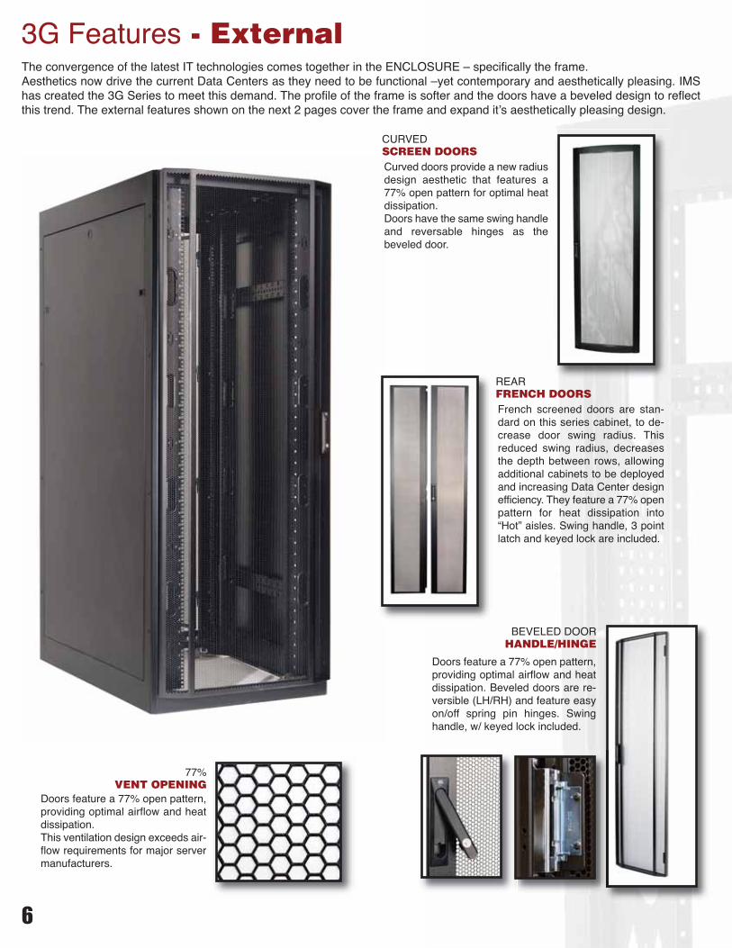
3G Features - ExternalThe convergence of the latest IT technologies comes together in the ENCLOSURE – specifically the frame.Aesthetics now drive the current Data Centers as they need to be functional –yet contemporary and aesthetically pleasing. IMShas created the 3G Series to meet this demand. The profile of the frame is softer and the doors have a beveled design to reflectthis trend. The external features shown on the next 2 pages cover the frame and expand it’s aesthetically pleasing design.
77%VENT OPENING
Doors feature a 77% open pattern,providing optimal airflow and heatdissipation.This ventilation design exceeds air-flow requirements for major servermanufacturers.
BEVELED DOORHANDLE/HINGE
Doors feature a 77% open pattern,providing optimal airflow and heatdissipation. Beveled doors are re-versible (LH/RH) and feature easyon/off spring pin hinges. Swinghandle, w/ keyed lock included.
REARFRENCH DOORSFrench screened doors are stan-dard on this series cabinet, to de-crease door swing radius. Thisreduced swing radius, decreasesthe depth between rows, allowingadditional cabinets to be deployedand increasing Data Center designefficiency. They feature a 77% openpattern for heat dissipation into“Hot” aisles. Swing handle, 3 pointlatch and keyed lock are included.
CURVEDSCREEN DOORSCurved doors provide a new radiusdesign aesthetic that features a77% open pattern for optimal heatdissipation.Doors have the same swing handleand reversable hinges as thebeveled door.

7
SIDEPANELPanels function as baffle OR side panels and can be used between joinedframes for thermal management. Easy-on and off side panels have a springtype finger latch, that slides to open or close, holding the panel in place.Locks are standard on all side panels. Locks can be ordered keyed alike orseparately per the customers specific design requirements. (Keyed sepa-rately is an option and quoted upon request.)
* BLANKINGPANEL
Blanking panels are tool-less andcover the unused rack units in thefront panel opening space of theserver cabinet. This quick and easyaccessory supplies 1/4 turn twist lockhardware with 16 ga. CRS enclosurepanels for simple installation.Blanking panels support efficient useof air intake by servers to cool frontto rear.When combined with server blowersthey are extremely efficient and costeffective resources to manage coldair distribution to server cabinets.
* EXTERNALCABLE TROUGH
Vertical cable troughs are avail-able in a 6" width with an overalldepth of 10". Troughs run verti-cally on the side of the frame, andcan be mounted front, rear orboth.This accessory provides an opti-mal raceway for cable bundlesand drops. Front doors provideeasy access, while cut-outs introughs supply pass thru egressfor patch panels. Grommets areincluded for side to side cableegress holes and side panels areavailable to finish off end bays.
TOPPANEL
Top panel is solid and has 8 ea.(10 ea for 48" depth consoles)cable egress points with plasticgrommets and cover plateslocated around the perimeter ofthe panel. This optimal egressdesign was configured to handlemost
* CABLE WIRINGSPACER KIT One spacer panel is required when
one external vertical cable trough orcable wiring spacer kit is imple-mented in console design.Spacer panel can be used betweentwo frames or at the end of a con-sole row with a trough side panel.See page 19 in this catalog for ap-plication reference.
Cable Wiring Spacer Kit – Kit includes a fulllength bottom spacer bracket that accepts afull length cover panel with finger pull incenter. System provides easy on/off accessto cabling or power mounted between twocabinets.Cable troughs, spacer panels or cablewiring spacer kits are be used in pairs ormixed and matched ( 2 per side) to achievenecessary application/design requirements.
* TROUGHSPACER PANEL
* Optional Features
cabling requirements.
IMS can supply standard or custom consoles. If additional in-formation or assistance is required contact your local salesrepresentative or IMS directly at 847-391-8100
IMS/AMCO is the perfect source for Equipment DistributionArea(EDA) cabinets for TIA-942 specification Data Centers. Wecan supply individual cabinets or room encompassing configura-tions to meet your exact design requirements.Our support team can assist through all aspects of your data pro-gram - from cabinet design configuration, power distribution,cable and cooling implementation and inventory management ofcompletely integrated consoles ready to ship per your schedule.IMS Is THE source for Adaptive Enclosures for IT environments.
8
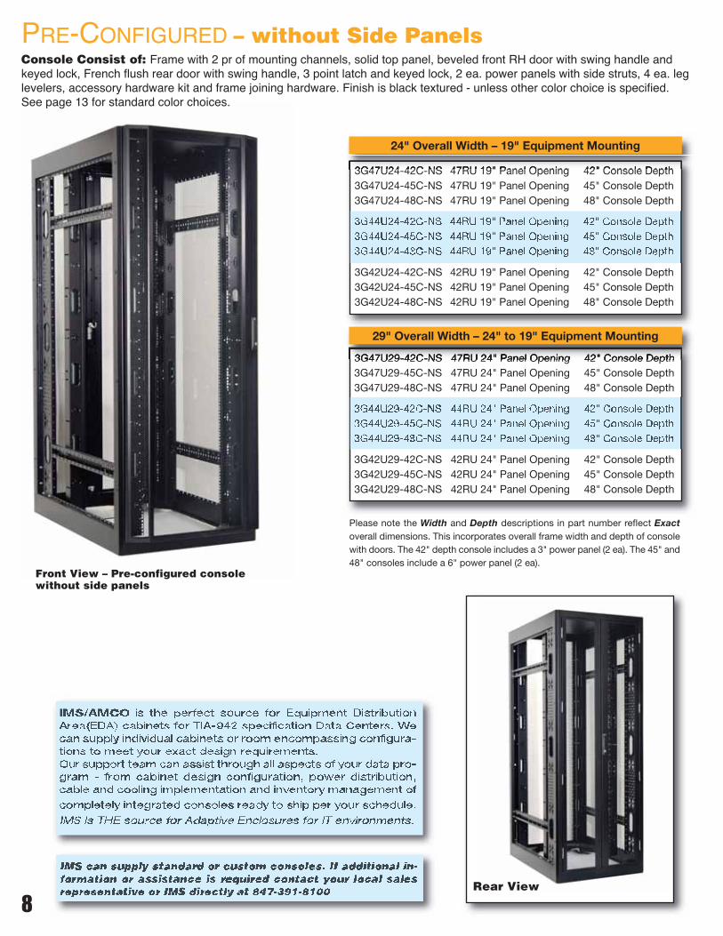
Console Consist of: Frame with 2 pr of mounting channels, solid top panel, beveled front RH door with swing handle andkeyed lock, French flush rear door with swing handle, 3 point latch and keyed lock, 2 ea. power panels with side struts, 4 ea. leglevelers, accessory hardware kit and frame joining hardware. Finish is black textured - unless other color choice is specified.See page 13 for standard color choices.
PRE-CONFIGURED – without Side Panels
3G47U29-42C-NS 47RU 24" Panel Opening 42" Console Depth3G47U29-45C-NS 47RU 24" Panel Opening 45" Console Depth3G47U29-48C-NS 47RU 24" Panel Opening 48" Console Depth
3G44U29-42C-NS 44RU 24" Panel Opening 42" Console Depth3G44U29-45C-NS 44RU 24" Panel Opening 45" Console Depth3G44U29-48C-NS 44RU 24" Panel Opening 48" Console Depth
3G42U29-42C-NS 42RU 24" Panel Opening 42" Console Depth3G42U29-45C-NS 42RU 24" Panel Opening 45" Console Depth3G42U29-48C-NS 42RU 24" Panel Opening 48" Console Depth
3G47U24-42C-NS 47RU 19" Panel Opening 42" Console Depth3G47U24-45C-NS 47RU 19" Panel Opening 45" Console Depth3G47U24-48C-NS 47RU 19" Panel Opening 48" Console Depth
3G44U24-42C-NS 44RU 19" Panel Opening 42" Console Depth3G44U24-45C-NS 44RU 19" Panel Opening 45" Console Depth3G44U24-48C-NS 44RU 19" Panel Opening 48" Console Depth
3G42U24-42C-NS 42RU 19" Panel Opening 42" Console Depth3G42U24-45C-NS 42RU 19" Panel Opening 45" Console Depth3G42U24-48C-NS 42RU 19" Panel Opening 48" Console Depth
Front View – Pre-configured consolewithout side panels
Rear View
24" Overall Width – 19" Equipment Mounting
29" Overall Width – 24" to 19" Equipment Mounting
Please note the Width and Depth descriptions in part number reflect Exactoverall dimensions. This incorporates overall frame width and depth of consolewith doors. The 42" depth console includes a 3" power panel (2 ea). The 45" and48" consoles include a 6" power panel (2 ea).

9
Console Consist of: Frame with 2 pr of mounting channels, solid top panel, 2 ea. solid side panels with keyed lock,beveled front RH door with swing handle and keyed lock, French flush rear door with swing handle, 3 point latch and keyedlock, 2 ea. power panels with side struts, 4 ea. leg levelers, accessory hardware kit and frame joining hardware. Finish isblack textured - unless other color choice is specified. See page 13 for standard color choices.
3G47U24-42C-S 47RU 19" Panel Opening 42" Console Depth3G47U24-45C-S 47RU 19" Panel Opening 45" Console Depth3G47U24-48C-S 47RU 19" Panel Opening 48" Console Depth
3G44U24-42C-S 44RU 19" Panel Opening 42" Console Depth3G44U24-45C-S 44RU 19" Panel Opening 45" Console Depth3G44U24-48C-S 44RU 19" Panel Opening 48" Console Depth
3G42U24-42C-S 42RU 19" Panel Opening 42" Console Depth3G42U24-45C-S 42RU 19" Panel Opening 45" Console Depth3G42U24-48C-S 42RU 19" Panel Opening 48" Console Depth
PRE-CONFIGURED – with Side Panels
3G47U29-42C-S 47RU 24" Panel Opening 42" Console Depth3G47U29-45C-S 47RU 24" Panel Opening 45" Console Depth3G47U29-48C-S 47RU 24" Panel Opening 48" Console Depth
3G44U29-42C-S 44RU 24" Panel Opening 42" Console Depth3G44U29-45C-S 44RU 24" Panel Opening 45" Console Depth3G44U29-48C-S 44RU 24" Panel Opening 48" Console Depth
3G42U29-42C-S 42RU 24" Panel Opening 42" Console Depth3G42U29-45C-S 42RU 24" Panel Opening 45" Console Depth3G42U29-48C-S 42RU 24" Panel Opening 48" Console Depth
Please note the Width and Depth descriptions in part number reflect Exactoverall dimensions. This incorporates overall frame width and depth of consolewith doors. The 42" depth console includes a 3" power panel (2 ea). The 45" and48" consoles include a 6" power panel (2 ea).
24" Overall Width – 19" Equipment Mounting
29" Overall Width – 24" to 19" Equipment Mounting
Front View – Pre-configured consolewith side panels
3G42U24-42F-FF-S 42RU 19" Panel Opening 42" Console Depth3G44U24-42F-FF-S 44RU 19" Panel Opening 42" Console Depth3G47U24-42F-FF-S 47RU 19" Panel Opening 42" Console Depth
24" Overall Width – 19" Equipment Mounting
3G42U29-42F-FF-S 42RU 24" Panel Opening 42" Console Depth3G44U29-42F-FF-S 44RU 24" Panel Opening 42" Console Depth3G47U29-42F-FF-S 47RU 29" Panel Opening 42" Console Depth
29" Overall Width – 24" to 19" Equipment Mounting
NEW Expanded Capacity Consoles.Frame features the 6" power panel in a TRUE 42" depth frame. Com-bined with the FLUSH screened front door this version of our pre-con-figured console provides an additional 3" of frame depth. This space canbe used for increased power or cabling requirements in a compact foot-print design. Reference flush door on page 18 of this catalog.Console Consists of: Frame, with 2 pair of mounting channels,solidtop panel, 2 ea. solid side panels with keyed lock, FLUSH screened doorw/swing handle and keyed lock, French flush screened door w/ swinghandle, 3 point latch and keyed lock, two 6" power panels w/ side struts,4 leg levelers, hardware kit and frame joining hardware.
Front View
10
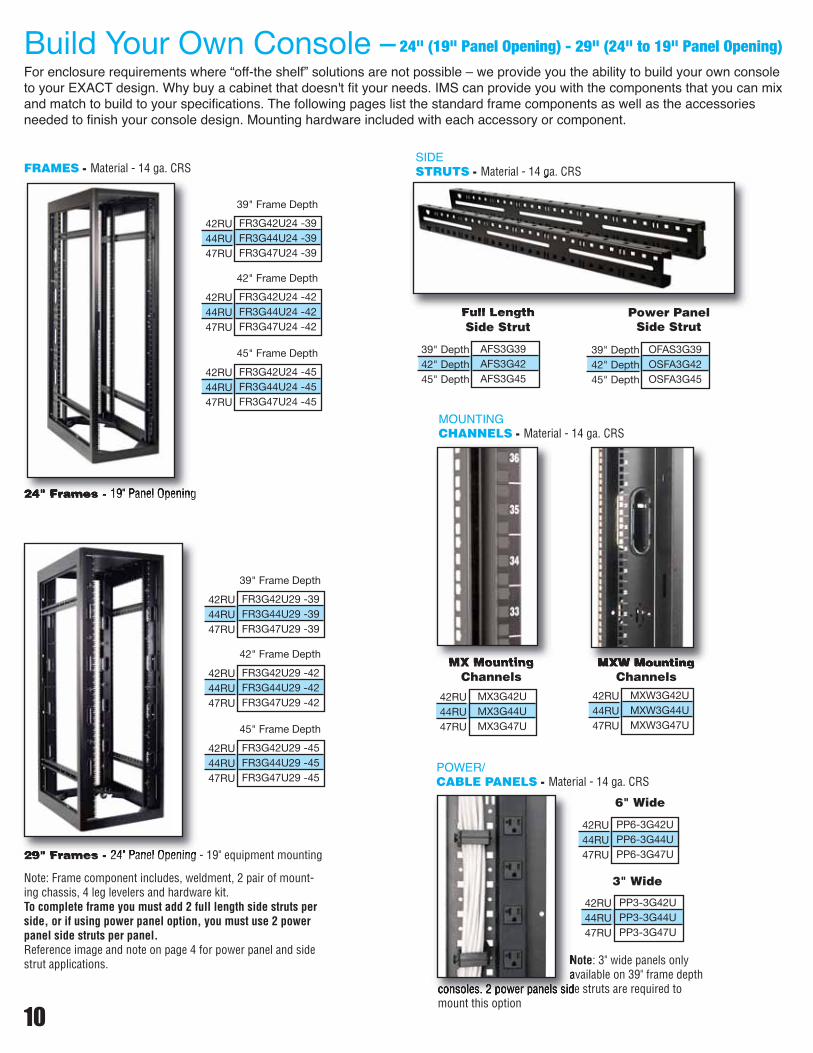
Build Your Own Console – 24" (19" Panel Opening) - 29" (24" to 19" Panel Opening)
For enclosure requirements where “off-the shelf” solutions are not possible – we provide you the ability to build your own consoleto your EXACT design. Why buy a cabinet that doesn't fit your needs. IMS can provide you with the components that you can mixand match to build to your specifications. The following pages list the standard frame components as well as the accessoriesneeded to finish your console design. Mounting hardware included with each accessory or component.
24" Frames - 19" Panel Opening
29" Frames - 24" Panel Opening - 19" equipment mounting
FRAMES - Material - 14 ga. CRS
FR3G42U24 -39FR3G44U24 -39FR3G47U24 -39
39" Frame Depth
42RU44RU47RU
MOUNTINGCHANNELS - Material - 14 ga. CRS
MX3G42UMX3G44UMX3G47U
42RU44RU47RU
MX MountingChannels
MXW3G42UMXW3G44UMXW3G47U
42RU44RU47RU
MXW MountingChannels
SIDESTRUTS - Material - 14 ga. CRS
AFS3G39AFS3G42AFS3G45
39" Depth42" Depth45" Depth
Full LengthSide Strut
OFAS3G39OSFA3G42OSFA3G45
39" Depth42" Depth45" Depth
Power PanelSide Strut
POWER/CABLE PANELS - Material - 14 ga. CRS
PP6-3G42UPP6-3G44UPP6-3G47U
42RU44RU47RU
6" Wide
PP3-3G42UPP3-3G44UPP3-3G47U
42RU44RU47RU
3" Wide
FR3G42U24 -45FR3G44U24 -45FR3G47U24 -45
45" Frame Depth
42RU44RU47RU
FR3G42U24 -42FR3G44U24 -42FR3G47U24 -42
42" Frame Depth
42RU44RU47RU
FR3G42U29 -39FR3G44U29 -39FR3G47U29 -39
39" Frame Depth
42RU44RU47RU
FR3G42U29 -45FR3G44U29 -45FR3G47U29 -45
45" Frame Depth
42RU44RU47RU
FR3G42U29 -42FR3G44U29 -42FR3G47U29 -42
42" Frame Depth
42RU44RU47RU
Note: Frame component includes, weldment, 2 pair of mount-ing chassis, 4 leg levelers and hardware kit.To complete frame you must add 2 full length side struts perside, or if using power panel option, you must use 2 powerpanel side struts per panel.Reference image and note on page 4 for power panel and sidestrut applications. Note: 3" wide panels only
available on 39" frame depthconsoles. 2 power panels side struts are required tomount this option
11
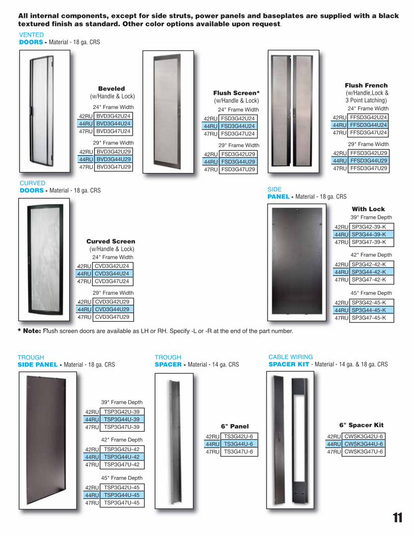
SIDEPANEL - Material - 18 ga. CRS
With Lock
VENTEDDOORS - Material - 18 ga. CRS
Beveled(w/Handle & Lock) Flush Screen*
(w/Handle & Lock)
Flush French(w/Handle,Lock &3 Point Latching)
BVD3G42U24BVD3G44U24BVD3G47U24
42RU44RU47RU
24" Frame Width
BVD3G42U29BVD3G44U29BVD3G47U29
42RU44RU47RU
29" Frame Width
FSD3G42U24FSD3G44U24FSD3G47U24
42RU44RU47RU
24" Frame Width
FSD3G42U29FSD3G44U29FSD3G47U29
42RU44RU47RU
29" Frame Width
FFSD3G42U24FFSD3G44U24FFSD3G47U24
42RU44RU47RU
24" Frame Width
FFSD3G42U29FFSD3G44U29FFSD3G47U29
42RU44RU47RU
29" Frame Width
TS3G42U-6TS3G44U-6TS3G47U-6
42RU44RU47RU
6" Panel
CWSK3G42U-6CWSK3G44U-6CWSK3G47U-6
42RU44RU47RU
CABLE WIRINGSPACER KIT - Material - 14 ga. & 18 ga. CRS
6" Spacer Kit
TROUGHSPACER - Material - 14 ga. CRS
TSP3G42U-39TSP3G44U-39TSP3G47U-39
39" Frame Depth
42RU44RU47RU
TSP3G42U-45TSP3G44U-45TSP3G47U-45
45" Frame Depth
42RU44RU47RU
TSP3G42U-42TSP3G44U-42TSP3G47U-42
42" Frame Depth
42RU44RU47RU
TROUGHSIDE PANEL - Material - 18 ga. CRS
All internal components, except for side struts, power panels and baseplates are supplied with a blacktextured finish as standard. Other color options available upon request.
* Note: Flush screen doors are available as LH or RH. Specify -L or -R at the end of the part number.
Curved Screen(w/Handle & Lock)
CVD3G42U24CVD3G44U24CVD3G47U24
42RU44RU47RU
24" Frame Width
CVD3G42U29CVD3G44U29CVD3G47U29
42RU44RU47RU
29" Frame Width
CURVEDDOORS - Material - 18 ga. CRS
SP3G42-39-KSP3G44-39-KSP3G47-39-K
39" Frame Depth
42RU44RU47RU
SP3G42-45-KSP3G44-45-KSP3G47-45-K
45" Frame Depth
42RU44RU47RU
SP3G42-42-KSP3G44-42-KSP3G47-42-K
42" Frame Depth
42RU44RU47RU
BPLT3G29-39BPLT3G29-42BPLT3G29-45
BPLT3G24-39BPLT3G24-42BPLT3G24-45
TPF3G29-39TPF3G29-42TPF3G29-45
TPF3G24-39TPF3G24-42TPF3G24-45
TPV3G29-39TPV3G29-42TPV3G29-45
TPV3G24-39TPV3G24-42TPV3G24-45
TPS3G29-39TPS3G29-42TPS3G29-45
TPS3G24-39TPS3G24-42TPS3G24-45
12
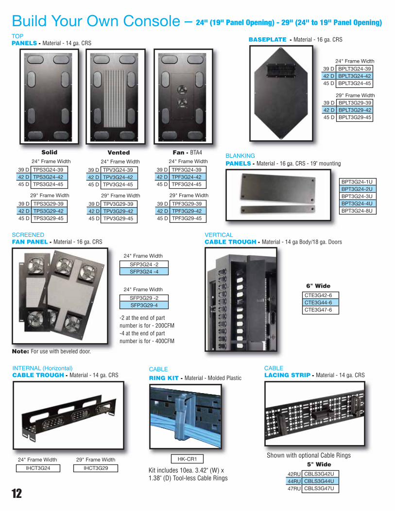
Build Your Own Console – 24" (19" Panel Opening) - 29" (24" to 19" Panel Opening)
TOPPANELS - Material - 14 ga. CRS BASEPLATE - Material - 16 ga. CRS
INTERNAL (Horizontal)CABLE TROUGH - Material - 14 ga. CRS
VERTICALCABLE TROUGH - Material - 14 ga Body/18 ga. Doors
CABLELACING STRIP - Material - 14 ga. CRS
CABLE
RING KIT - Material - Molded Plastic
Solid24" Frame Width
29" Frame Width
Vented24" Frame Width
29" Frame Width
Fan - BTA424" Frame Width
29" Frame Width
24" Frame Width
29" Frame Width
IHCT3G24
24" Frame Width
CTE3G42-6CTE3G44-6CTE3G47-6
39 D42 D45 D
6" Wide
HK-CR1
CBLS3G42UCBLS3G44UCBLS3G47U
42RU44RU47RU
5" Wide
24" Frame Width
BLANKINGPANELS - Material - 16 ga. CRS - 19" mounting
BPT3G24-1UBPT3G24-2UBPT3G24-3UBPT3G24-4UBPT3G24-8U
IHCT3G29
29" Frame Width
SCREENEDFAN PANEL - Material - 16 ga. CRS
-2 at the end of partnumber is for - 200CFM-4 at the end of partnumber is for - 400CFM
Kit includes 10ea. 3.42" (W) x1.38" (D) Tool-less Cable Rings
Shown with optional Cable Rings
Note: For use with beveled door.
SFP3G24 -2SFP3G24 -4
24" Frame Width
SFP3G29 -2SFP3G29-4
39 D42 D45 D
39 D42 D45 D
39 D42 D45 D
39 D42 D45 D
39 D42 D45 D
39 D42 D45 D
39 D42 D45 D

1 43
2
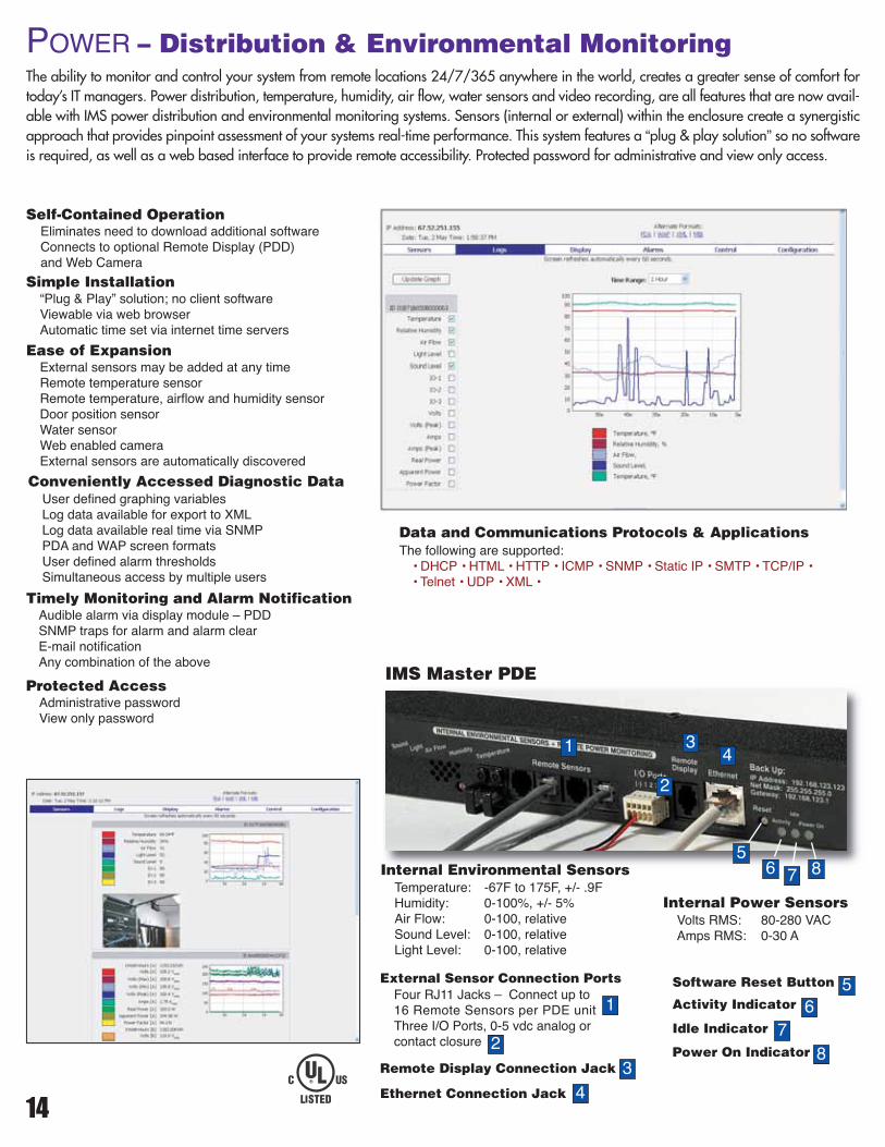
576 8Internal Environmental Sensors
Temperature: -67F to 175F, +/- .9FHumidity: 0-100%, +/- 5%Air Flow: 0-100, relativeSound Level: 0-100, relativeLight Level: 0-100, relative
Internal Power SensorsVolts RMS: 80-280 VACAmps RMS: 0-30 A
External Sensor Connection PortsFour RJ11 Jacks – Connect up to16 Remote Sensors per PDE unitThree I/O Ports, 0-5 vdc analog orcontact closure
Ethernet Connection Jack
Remote Display Connection Jack
Software Reset Button
Power On Indicator
Activity Indicator
Idle Indicator
1
43
5
76
8
14
The ability to monitor and control your system from remote locations 24/7/365 anywhere in the world, creates a greater sense of comfort fortoday’s IT managers. Power distribution, temperature, humidity, air flow, water sensors and video recording, are all features that are now avail-able with IMS power distribution and environmental monitoring systems. Sensors (internal or external) within the enclosure create a synergisticapproach that provides pinpoint assessment of your systems real-time performance. This system features a “plug & play solution” so no softwareis required, as well as a web based interface to provide remote accessibility. Protected password for administrative and view only access.
POWER – Distribution & Environmental Monitoring
Self-Contained OperationEliminates need to download additional softwareConnects to optional Remote Display (PDD)and Web Camera
Simple Installation“Plug & Play” solution; no client softwareViewable via web browserAutomatic time set via internet time servers
Ease of ExpansionExternal sensors may be added at any timeRemote temperature sensorRemote temperature, airflow and humidity sensorDoor position sensorWater sensorWeb enabled cameraExternal sensors are automatically discovered
Conveniently Accessed Diagnostic DataUser defined graphing variablesLog data available for export to XMLLog data available real time via SNMPPDA and WAP screen formatsUser defined alarm thresholdsSimultaneous access by multiple users
Timely Monitoring and Alarm NotificationAudible alarm via display module – PDDSNMP traps for alarm and alarm clearE-mail notificationAny combination of the above
Protected AccessAdministrative passwordView only password
Data and Communications Protocols & ApplicationsThe following are supported:• DHCP • HTML • HTTP • ICMP • SNMP • Static IP • SMTP • TCP/IP •• Telnet • UDP • XML •
2
IMS Master PDE

Vertical Power Distribution, Environmental and Power Monitoring - 20 Amp - 250 Volt – 20 Outlets – IEC *Part Circuit UL Remote
Number Amps Volts Receptacle Qty. Plug Breaker Designation Display
PDS6620-20-250-NB10 20 250 C-13 20 6-20P No UL &c-UL Listed 60950 Optional
Remote Display(visual display & audible alarm)
15
Vertical Power Distribution, Environmental and Power Monitoring - 30 Amp - 125 or 250 Volt – 24/30 Outlets – NEMA *Part Circuit UL Remote
Number Amps Volts Receptacle Qty. Plug Breaker Designation Display
PDE6624-30-125-2010 30 125 5-20R 24 L5-30P Twist Lock Yes UL &c-UL Listed 60950 OptionalPDE6630-30-250-2010 30 250 6-20R 30 L6-20P Twist Lock Yes UL &c-UL Listed 60950 OptionalPDE6624-30-250-2010 30 250 6-20R 24 L6-30P Twist Lock Yes UL &c-UL Listed 60950 Optional
Horizontal Power Distribution, Environmental/Power Monitoring - 20 Amp - 125, 250 or 125/250 Volt – 10/12 Outlets – IEC & NEMA*Part Circuit UL Remote
Number Amps Volts Receptacle Qty. Plug Breaker Designation Display
PDE1910-20-125-NB10 20 125 5-20R 10 5-20P Straight Blade No UL &c-UL Listed 60950 OptionalPDE1910-20-250-NB10 20 250 6-20R 10 6-20P Straight Blade No UL &c-UL Listed 60950 OptionalPDE1912-20-DV-NBNC 20 125/250 C-13 12 C-20 Inlet * No UL &c-UL Listed 60950 Optional
Remote Sensors –Remote Temperature, Airflow & Humidity Sensor – PDDRemote Temperature SensorDoor Position SensorWater SensorWeb Enabled Camera
POWER – AccessoriesIMS provides a complete line of sensors, displays and web cams for it's EnvironmentalMonitoring Series. Specific information of each item is available by contacting IMS direct.
Vertical Power Distribution, Environmental and Power Monitoring - 30 Amp - 250 Volt – 24 Outlets – IEC *Part Circuit UL Remote
Number Amps Volts Receptacle Qty. Plug Breaker Designation Display
PDS6630-30-250-2010 30 250 C-13 24 L6-30P Twist Lock Yes UL &c-UL Listed 60950 Optional
* All Units come Standard with 10ft. Cord – Except PDE1912-20-DV-NBNC which has a C-20 inlet
All Power Distribution units listed on this page have the monitoring features shown on page 14. The PDD Unit option is for an external mon-itor that can mount outside of the of frame. See image at the bottom of this page
16
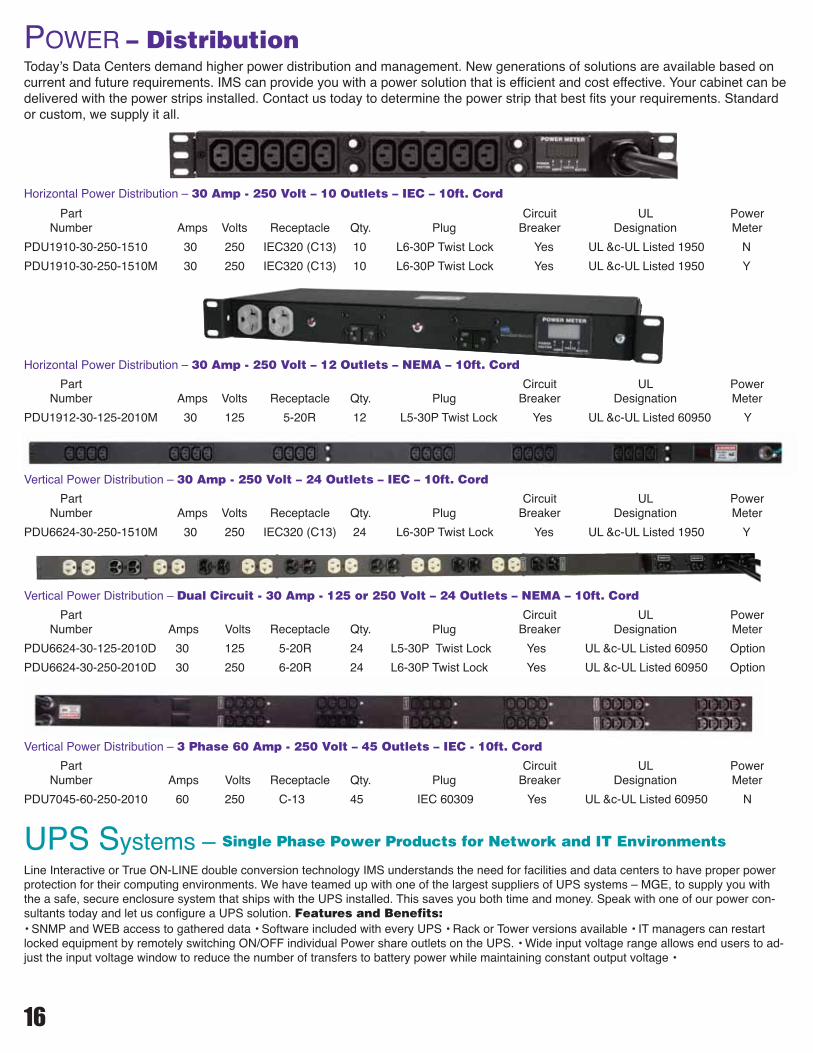
Today’s Data Centers demand higher power distribution and management. New generations of solutions are available based oncurrent and future requirements. IMS can provide you with a power solution that is efficient and cost effective. Your cabinet can bedelivered with the power strips installed. Contact us today to determine the power strip that best fits your requirements. Standardor custom, we supply it all.
Vertical Power Distribution – Dual Circuit - 30 Amp - 125 or 250 Volt – 24 Outlets – NEMA – 10ft. Cord
Part Circuit UL PowerNumber Amps Volts Receptacle Qty. Plug Breaker Designation Meter
PDU6624-30-125-2010D 30 125 5-20R 24 L5-30P Twist Lock Yes UL &c-UL Listed 60950 Option
PDU6624-30-250-2010D 30 250 6-20R 24 L6-30P Twist Lock Yes UL &c-UL Listed 60950 Option
Vertical Power Distribution – 30 Amp - 250 Volt – 24 Outlets – IEC – 10ft. Cord
Part Circuit UL PowerNumber Amps Volts Receptacle Qty. Plug Breaker Designation Meter
PDU6624-30-250-1510M 30 250 IEC320 (C13) 24 L6-30P Twist Lock Yes UL &c-UL Listed 1950 Y
Horizontal Power Distribution – 30 Amp - 250 Volt – 10 Outlets – IEC – 10ft. Cord
Part Circuit UL PowerNumber Amps Volts Receptacle Qty. Plug Breaker Designation Meter
PDU1910-30-250-1510 30 250 IEC320 (C13) 10 L6-30P Twist Lock Yes UL &c-UL Listed 1950 N
PDU1910-30-250-1510M 30 250 IEC320 (C13) 10 L6-30P Twist Lock Yes UL &c-UL Listed 1950 Y
Horizontal Power Distribution – 30 Amp - 250 Volt – 12 Outlets – NEMA – 10ft. Cord
Part Circuit UL PowerNumber Amps Volts Receptacle Qty. Plug Breaker Designation Meter
PDU1912-30-125-2010M 30 125 5-20R 12 L5-30P Twist Lock Yes UL &c-UL Listed 60950 Y
POWER – Distribution
UPS Systems – Single Phase Power Products for Network and IT Environments
• SNMP and WEB access to gathered data • Software included with every UPS • Rack or Tower versions available • IT managers can restartlocked equipment by remotely switching ON/OFF individual Power share outlets on the UPS. • Wide input voltage range allows end users to ad-just the input voltage window to reduce the number of transfers to battery power while maintaining constant output voltage •
Vertical Power Distribution – 3 Phase 60 Amp - 250 Volt – 45 Outlets – IEC - 10ft. Cord
Part Circuit UL PowerNumber Amps Volts Receptacle Qty. Plug Breaker Designation Meter
PDU7045-60-250-2010 60 250 C-13 45 IEC 60309 Yes UL &c-UL Listed 60950 N
Line Interactive or True ON-LINE double conversion technology IMS understands the need for facilities and data centers to have proper powerprotection for their computing environments. We have teamed up with one of the largest suppliers of UPS systems – MGE, to supply you withthe a safe, secure enclosure system that ships with the UPS installed. This saves you both time and money. Speak with one of our power con-sultants today and let us configure a UPS solution. Features and Benefits:
17
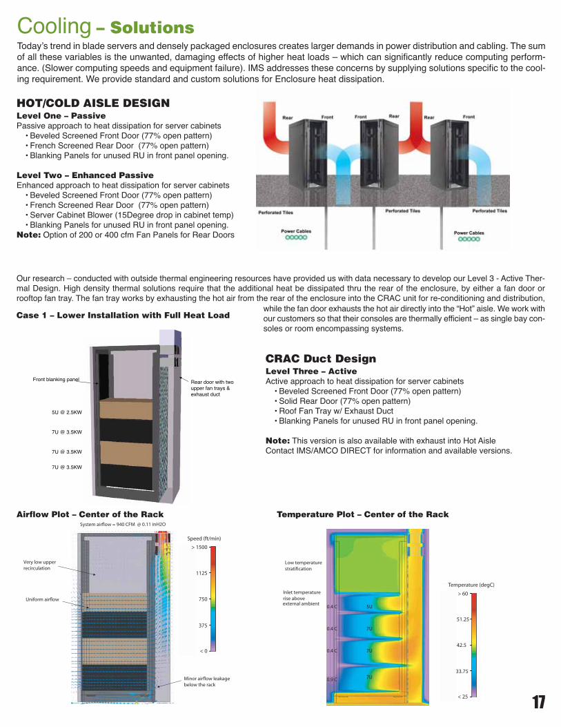
Cooling – Solutions
Front blanking panel
7U @ 3.5KW
7U @ 3.5KW
7U @ 3.5KW
5U @ 2.5KW
Rear door with twoupper fan trays &exhaust duct
Uniform airflow
Very low upper recirculation
Minor airflow leakage below the rack
System airflow = 940 CFM @ 0.11 inH2O
> 1500
< 0
1125
750
375
Speed (ft/min)
Today’s trend in blade servers and densely packaged enclosures creates larger demands in power distribution and cabling. The sumof all these variables is the unwanted, damaging effects of higher heat loads – which can significantly reduce computing perform-ance. (Slower computing speeds and equipment failure). IMS addresses these concerns by supplying solutions specific to the cool-ing requirement. We provide standard and custom solutions for Enclosure heat dissipation.
0.4 C
Inlet temperature rise aboveexternal ambient
0.4 C
0.4 C
0.9 C
Low temperaturestratification
7U
7U
7U
5U
> 60
< 25
51.25
42.5
33.75
Temperature (degC)
Case 1 – Lower Installation with Full Heat Load
Airflow Plot – Center of the Rack Temperature Plot – Center of the Rack
HOT/COLD AISLE DESIGNLevel One – PassivePassive approach to heat dissipation for server cabinets• Beveled Screened Front Door (77% open pattern)• French Screened Rear Door (77% open pattern)• Blanking Panels for unused RU in front panel opening.
Level Two – Enhanced PassiveEnhanced approach to heat dissipation for server cabinets• Beveled Screened Front Door (77% open pattern)• French Screened Rear Door (77% open pattern)• Server Cabinet Blower (15Degree drop in cabinet temp)• Blanking Panels for unused RU in front panel opening.
Note: Option of 200 or 400 cfm Fan Panels for Rear Doors
CRAC Duct DesignLevel Three – ActiveActive approach to heat dissipation for server cabinets• Beveled Screened Front Door (77% open pattern)• Solid Rear Door (77% open pattern)• Roof Fan Tray w/ Exhaust Duct• Blanking Panels for unused RU in front panel opening.
Note: This version is also available with exhaust into Hot AisleContact IMS/AMCO DIRECT for information and available versions.
Our research – conducted with outside thermal engineering resources have provided us with data necessary to develop our Level 3 - Active Ther-mal Design. High density thermal solutions require that the additional heat be dissipated thru the rear of the enclosure, by either a fan door orrooftop fan tray. The fan tray works by exhausting the hot air from the rear of the enclosure into the CRAC unit for re-conditioning and distribution,
while the fan door exhausts the hot air directly into the “Hot” aisle. We work withour customers so that their consoles are thermally efficient – as single bay con-soles or room encompassing systems.

A
B2.75
B
A
.56
A A
.563.00
B B
BVD3G42U24 75.81" 22.57"BVD3G42U29 75.81" 27.57"BVD3G44U24 79.31" 22.57"BVD3G44U29 79.31" 27.57"BVD3G47U24 84.56" 22.57"BVD3G47U29 84.56" 27.57"
FSD3G42U24 73.50" 20.28"FSD3G42U29 73.50" 25.28"FSD3G44U24 77.00" 20.28"FSD3G44U29 77.00" 25.28"FSD3G47U24 82.25" 20.28"FSD3G47U29 82.25" 25.28"
FFSD3G42U24 73.50" 20.18"FFSD3G42U29 73.50" 25.18"FFSD3G44U24 77.00" 20.18"FFSD3G44U29 77.00" 25.18"FFSD3G47U24 82.25" 20.18"FFSD3G47U29 82.25" 25.18"
18
3G – Technical Reference
CONSOLE ASSYFRONT VIEW
TOP VIEW
SIDE VIEW REAR VIEW
.88 Min.
A
24.00 or 29.00
E
F
2.875
B
1.813
D 29.21 2.00
4.50
4.50
C
3.0 X 6.5 KNOCK-OUT HOLES
DOORS - Material - 18 ga. CRS — Perforated area .25 Honeycomb, 77% Open
Note: For Frame dimension without Beveled door see Dimension“E” in Chart.
A B C D E F
Dimensions29"Part No.
3G42U24-42 3G42U29-42 78.56" 73.88" 69.56" 7.79" 39.00" 42.00"3G42U24-45 3G42U29-45 78.56" 73.88" 69.56" 10.79" 42.00" 45.00"3G42U24-48 3G42U29-48 78.56" 73.88" 69.56" 13.79" 45.00" 48.00"3G44U24-42 3G44U29-42 82.06" 77.38" 73.06" 7.79" 39.00" 42.00"3G44U24-45 3G44U29-45 82.06" 77.38" 73.06" 10.79" 42.00" 45.00"3G44U24-48 3G44U29-48 82.06" 77.38" 73.06" 13.79" 45.00" 48.00"3G47U24-42 3G47U29-42 87.31" 82.63" 78.31" 7.79" 39.00" 42.00"3G47U24-45 3G47U29-45 87.31" 82.63" 78.31" 10.79" 42.00" 45.00"3G47U24-48 3G47U29-48 87.31" 82.63" 78.31" 13.79" 45.00" 48.00"
The following two pages provide dimensional references for the 3G Series Consoles as well as application illustrations for thetrough components. For additional technical information contact IMS direct.
A B
DimensionsPart No.
Beveled Door Flush Door Flush French Door
A B
DimensionsPart No.
A B
DimensionsPart No.
24"Part No.
Note: 3" Power Panel is included for 42" depth consoles. 6" included for 45" & 48" depth consoles
CVD3G42U24 75.81" 22.57"CVD3G42U29 75.81" 27.57"CVD3G44U24 79.31" 22.57"CVD3G44U29 79.31" 27.57"CVD3G47U24 84.56" 22.57"CVD3G47U29 84.56" 27.57"
A B
DimensionsPart No.
Curved Door

A
B
SP3G42-39-K 69.46" 33.31"SP3G44-39-K 72.96" 33.31"SP3G47-39-K 78.21" 33.31"SP3G42-42-K 69.46" 36.31"SP3G44-42-K 72.96" 36.31"SP3G47-42-K 78.21" 36.31"SP3G42-45-K 69.46" 39.31"SP3G44-45-K 72.96" 39.31"SP3G47-45-K 78.21" 39.31"
19
TOPPANELS - Material - 16 ga. CRS
TROUGHSYSTEMS - Material - 14 & 18 ga. CRS
SIDEPANELS - Material - 18 ga. CRS
Cable Trough & Spacer Kit Double Cable Trough
Double Cable Trough& End Panel
Cable Trough withSpacer & End Panel
39" & 42" Frame Depth24" - 20.75"29" - 25.75"
39" - 33.25"42" - 36.25"
39" - 33.25"42" - 36.25"
45" Frame Depth24" - 20.75"29" - 25.75"
45" - 39.25"
45" - 39.25"
Cable egress holes are 3.00" X 6.50" and includegrommet & dust covers.
A B
DimensionsPart No.
Vertical troughs can be used in any combination with trough spacers or cable wiring spacer kit.They can be used between bays or at the end of console rows. Side panels also available.

ENGINEERED PRODUCTS, LLC
TM
1 Innovation Drive, Des Plaines, IL 60016 •Ph-847-391-8100 • Fax-847-391-8354 • www. imsep.com •
A. Choice of Method of ShipmentUnless otherwise specified, IMS Engineered Productsframes are shipped as individual modules per ISTA pack-aging certification with single width components assem-bled on the frame. Upon request, console arrangementswill be completely assembled at the factory and shippedlike furniture, via van, at no additional charge for assem-bly. Console arrangements may also be crated for ship-ment. Crating charges will be quoted for each such order,as console arrangements vary.
B. Design ChangesTo allow continued progress, improvement, and adapt-ability in an advancing industry, IMS Engineered Prod-ucts reserves the right to make product changes asdeemed necessary.
C. Price DiscountsPurchase orders cannot be combined for discount advan-
tages.
D. Proprietary RightsThe catalog and drawings contain information deemedproprietary to IMS Engineered Products and are to beused only for the purposes for which they are submittedand, further, shall not be copied in whole or in part with-out the prior written consent of IMS Engineered Products.
E. Cancellation & ReturnCancellation and return charges begin at 40% with a min-imum of $50.00, depending on the nature of the order andthe extent to which it has been processed. All returnshave a 30 day – upon receipt – time limit. Returns mustbe freight prepaid and not made without the prior writtenapproval of IMS Engineered Products.
F. TermsAll quotations, order confirmations, published prices, anddiscounts based on delivery F.O.B. IMS Engineered Prod-ucts, 1 Innovation Drive, Des Plaines, IL freight collect.Invoice payment terms—net 30 days.
G. Sales RepresentationExperienced factory sales representatives in all principlecities of the U.S.A., Canada and Mexico. Ask for salesrepresentative listing. IMS Engineered Products equip-ment is thoroughly inspected prior to shipment. NO re-turns of damaged equipment will be accepted withoutprior written approval of IMS Engineered Products.
Limited WarrantyIMS Engineered Products will repair or replace enclo-sures, accessories, and components manufactured byIMS Engineered Products that are proven to be defec-tive in material or factory workmanship under normal useduring the Period of this Warranty.
Warranty PeriodOne year from date of purchase.This warranty does not cover1) Failure in whole or part resulting from misuse, alter-ation, excessive temperature, excessive humidity, corro-sive environment, or lack of maintenance. 2. Anymaterials or components used or manufactured pursuantto the purchaser’s specifications. 3) Deterioration due tonormal use and exposure. 4) Items ordered in error or notrequired.
Power/AccessoriesWarranty as specified by manufacturer.
Warranty RepairPurchaser shall obtain controlled authorization number be-fore returning any items alleged to be defective to IMS En-gineered Products.
InspectionIMS Engineered Products shall have the right to inspectany and all allegedly defective items on-site at pur-chaser’s convenience.
Disclaimer of Consequential Damagesand Limitations of Implied WarrantyIMS Engineered Products disclaims any responsibility forloss of time or use of parts or equipment wherein IMS En-gineered Products enclosures, components, or acces-sories are used, transportation or any other incidental orconsequential damage; and any implied Warranties in-cluding the implied Warranty of merchantability and fit-ness for intended use are limited to the duration of thiswritten Warranty.
WARRANTY & POLICIES
KSP10081K