3kc18036ababtqzza_v1_alcatel-lucent 1646 synchronous multiplexer compact (smc) release 2.1 user...
TRANSCRIPT

Title page
Alcatel-Lucent
1646 Synchronous Multiplexer Compact (SMC) | Release
2.1
User Provisioning Guide
3KC18036ABABTQZZA
Issue 1
July 2011

Legal notice
Legal notice
Alcatel, Lucent, Alcatel-Lucent and the Alcatel-Lucent logo are trademarks of Alcatel-Lucent. All other trademarks are the property of their respective
owners.
The information presented is subject to change without notice. Alcatel-Lucent assumes no responsibility for inaccuracies contained herein.
Copyright © 2011 Alcatel-Lucent. All rights reserved.
Notice
The information in this document is subject to change without notice. Although every effort has been made to make this document as accurate, complete, and
clear as possible, Alcatel-Lucent and its predecessors assume no responsibility for any errors that appear in this document.
Security Statement
In rare instances, unauthorized individuals make connections to the telecommunications network. In such an event, applicable tariffs require that the
customer pay all network charges for traffic. Alcatel-Lucent and its predecessors cannot be responsible for such charges and will not make any allowance or
give any credit for charges that result from unauthorized access.
Limited warranty
Alcatel-Lucent provides a limited warranty for this product. For more information, consult your local Alcatel-Lucent customer support team.
Ordering information
To order more copies of this document or other Alcatel-Lucent documents, please access the Online Customer Support (OLCS) (https://support.lucent.com).
Information product support
To comment on this information product, go to the Online Comment Form (http://www.alcatel-lucent-info.com/comments/enus/) or email your comments to
the Comments Hotline ([email protected]).

Contents
About this document
Purpose ........................................................................................................................................................................................... xxixxi
Intended audience ...................................................................................................................................................................... xxixxi
How to use this document ....................................................................................................................................................... xxixxi
Signal words ............................................................................................................................................................................... xxiixxii
Conventions used .................................................................................................................................................................... xxiiixxiii
Related information ................................................................................................................................................................ xxiiixxiii
Technical support ..................................................................................................................................................................... xxivxxiv
How to order .............................................................................................................................................................................. xxivxxiv
How to comment ...................................................................................................................................................................... xxivxxiv
1 Getting Started
Overview ...................................................................................................................................................................................... 1-11-1
ZIC Functionality ...................................................................................................................................................................... 1-11-1
2 System Management
Overview ...................................................................................................................................................................................... 2-12-1
ZIC overview .............................................................................................................................................................................. 2-22-2
Procedure 2-1: Establish ZIC session ................................................................................................................................ 2-42-4
ZIC icons and symbols ........................................................................................................................................................... 2-62-6
Menus ............................................................................................................................................................................................ 2-72-7
Equipment menu ....................................................................................................................................................................... 2-82-8
Connection menu ...................................................................................................................................................................... 2-82-8
Data menu .................................................................................................................................................................................... 2-92-9
....................................................................................................................................................................................................................................
1646 SMC
3KC18036ABABTQZZA Release 2.1
Issue 1 July 2011
iii

Communication menu ........................................................................................................................................................... 2-102-10
Alarms menu ............................................................................................................................................................................ 2-102-10
Protection menu ...................................................................................................................................................................... 2-112-11
Synchonization menu ............................................................................................................................................................ 2-112-11
System Management menu ................................................................................................................................................. 2-122-12
Security menu .......................................................................................................................................................................... 2-122-12
Tools menu ................................................................................................................................................................................ 2-132-13
Help menu ................................................................................................................................................................................. 2-132-13
3 Equipment management
Overview ...................................................................................................................................................................................... 3-13-1
Procedure 3-1: Configure a board ....................................................................................................................................... 3-13-1
Procedure 3-2: Configure a port .......................................................................................................................................... 3-53-5
Procedure 3-3: Housekeeping support ............................................................................................................................ 3-123-12
4 Ethernet Functions
Overview ...................................................................................................................................................................................... 4-14-1
Procedure 4-1: Traffic descriptor ........................................................................................................................................ 4-24-2
Procedure 4-2: Resource Availability ................................................................................................................................ 4-54-5
Procedure 4-3: MAC Access Control List management ............................................................................................. 4-84-8
Procedure 4-4: VLAN Profile ............................................................................................................................................ 4-104-10
Procedure 4-5: Create color profile .................................................................................................................................. 4-114-11
Procedure 4-6: Bridge configuration ............................................................................................................................... 4-134-13
Procedure 4-7: IGMP management ................................................................................................................................. 4-144-14
Procedure 4-8: Create ASAP list ....................................................................................................................................... 4-164-16
Procedure 4-9: Global setting ............................................................................................................................................ 4-184-18
Procedure 4-10: Create maintenance domain .............................................................................................................. 4-194-19
Procedure 4-11: Create maintenance association ....................................................................................................... 4-204-20
Procedure 4-12: Create MEP ............................................................................................................................................. 4-234-23
Procedure 4-13: EFM tool ................................................................................................................................................... 4-254-25
Procedure 4-14: Configure EFM tool ............................................................................................................................. 4-264-26
Contents
....................................................................................................................................................................................................................................
....................................................................................................................................................................................................................................
iv 1646 SMC
3KC18036ABABTQZZA Release 2.1
Issue 1 July 2011

Procedure 4-15: Create VLAN .......................................................................................................................................... 4-284-28
Procedure 4-16: ConfigureVLAN .................................................................................................................................... 4-294-29
Procedure 4-17: Dynamic filtering DB .......................................................................................................................... 4-304-30
Procedure 4-18: Configure static unicast filtering ..................................................................................................... 4-314-31
Procedure 4-19: Configure static multicast filtering ................................................................................................. 4-324-32
Procedure 4-20: Ethernet P2P XC .................................................................................................................................... 4-344-34
5 Synchronization
Overview ...................................................................................................................................................................................... 5-15-1
Synchronization menu ............................................................................................................................................................. 5-15-1
Procedure 5-1: Modify BITS-0 ............................................................................................................................................ 5-25-2
Procedure 5-2: Modify BITS-OUT .................................................................................................................................... 5-35-3
Procedure 5-3: Administer system timing BITS ............................................................................................................ 5-55-5
Synchronization outgoing ................................................................................................................................................... 5-125-12
6 Alarm Management
Overview ...................................................................................................................................................................................... 6-16-1
Procedure 6-1: Provision alarm severity assignment profiles .................................................................................. 6-16-1
Procedure 6-2: ALM cutoff ................................................................................................................................................... 6-46-4
Procedure 6-3: ALM resynch. .............................................................................................................................................. 6-56-5
Procedure 6-4: Condition log ............................................................................................................................................... 6-66-6
7 Security
Overview ...................................................................................................................................................................................... 7-17-1
Procedure 7-1: Change user password ............................................................................................................................. 7-27-2
Procedure 7-2: Retrieve user information ........................................................................................................................ 7-27-2
Procedure 7-3: Create user account .................................................................................................................................... 7-47-4
Procedure 7-4: Change user account ................................................................................................................................. 7-57-5
Procedure 7-5: Modify account default settings ............................................................................................................ 7-87-8
Procedure 7-6: View current sessions ................................................................................................................................ 7-97-9
Procedure 7-7: Modify command privileges ................................................................................................................ 7-107-10
Contents
....................................................................................................................................................................................................................................
....................................................................................................................................................................................................................................
1646 SMC
3KC18036ABABTQZZA Release 2.1
Issue 1 July 2011
v

Procedure 7-8: Manage audit ............................................................................................................................................. 7-127-12
Procedure 7-9: Log settings ................................................................................................................................................ 7-157-15
Procedure 7-10: Modify in progress message settings ............................................................................................. 7-167-16
8 Provisioning: Detailed level Procedures
Overview ...................................................................................................................................................................................... 8-18-1
Procedure 8-1: Log into the system ................................................................................................................................... 8-28-2
Procedure 8-2: Log out of the system ............................................................................................................................... 8-38-3
Procedure 8-3: Retrieve software version ........................................................................................................................ 8-48-4
Procedure 8-4: Search VCn cross-connection ................................................................................................................ 8-68-6
Procedure 8-5: Initialize and Upgrade with a new release ........................................................................................ 8-98-9
Procedure 8-6: DB management remote file copy ..................................................................................................... 8-108-10
Procedure 8-7: DB management cancel remote file copy ....................................................................................... 8-138-13
Procedure 8-8: Network Element management ........................................................................................................... 8-148-14
Procedure 8-9: Change site identifier .............................................................................................................................. 8-158-15
Procedure 8-10: LAC Management ................................................................................................................................. 8-168-16
Procedure 8-11: MAC File Collection ............................................................................................................................ 8-188-18
Procedure 8-12: Administer NTP ..................................................................................................................................... 8-198-19
Procedure 8-13: Network IF ............................................................................................................................................... 8-228-22
Procedure 8-14: Create XC Overhead ............................................................................................................................ 8-248-24
Procedure 8-15: IP Address ................................................................................................................................................ 8-268-26
Procedure 8-16: Configure IP route ................................................................................................................................. 8-278-27
Procedure 8-17: OSI management ................................................................................................................................... 8-298-29
Procedure 8-18: Create linear MSP ................................................................................................................................. 8-318-31
Procedure 8-19: Create MS-SPRing ................................................................................................................................ 8-338-33
Procedure 8-20: LAG management ................................................................................................................................. 8-358-35
Procedure 8-21: Remove LAG member ........................................................................................................................ 8-408-40
Procedure 8-22: Retrieve system information ............................................................................................................. 8-438-43
Procedure 8-23: Create IP route ........................................................................................................................................ 8-458-45
Procedure 8-24: Create IP tunnel ...................................................................................................................................... 8-478-47
Contents
....................................................................................................................................................................................................................................
....................................................................................................................................................................................................................................
vi 1646 SMC
3KC18036ABABTQZZA Release 2.1
Issue 1 July 2011

Procedure 8-25: NE TL1 Parameter ................................................................................................................................ 8-498-49
Procedure 8-26: Create FTP Server Configuration .................................................................................................... 8-498-49
Glossary
Index
Contents
....................................................................................................................................................................................................................................
....................................................................................................................................................................................................................................
1646 SMC
3KC18036ABABTQZZA Release 2.1
Issue 1 July 2011
vii

Contents
....................................................................................................................................................................................................................................
....................................................................................................................................................................................................................................
viii 1646 SMC
3KC18036ABABTQZZA Release 2.1
Issue 1 July 2011

List of tables
1 Signal words for hazard severity ........................................................................................................................ xxiixxii
3-1 Board xx panel parameters ..................................................................................................................................... 3-23-2
3-2 Board xx Restart panel parameters ..................................................................................................................... 3-33-3
3-3 State panel parameters ............................................................................................................................................. 3-73-7
3-4 Input points attributes panel parameters ......................................................................................................... 3-133-13
4-1 Traffic descriptor panel parameters ..................................................................................................................... 4-24-2
4-2 Service type parameters .......................................................................................................................................... 4-44-4
4-3 Resource Management Pool parameters ........................................................................................................... 4-74-7
4-4 Modify MAC Access Control panel parameters ............................................................................................ 4-94-9
4-5 VLAN Protocol Profile panel parameters ...................................................................................................... 4-114-11
4-6 Color Profile panel parameters ........................................................................................................................... 4-124-12
4-7 ASAP panel parameters ........................................................................................................................................ 4-174-17
4-8 Maintenance Domain panel parameters .......................................................................................................... 4-194-19
4-9 Maintenance Domain panel parameters .......................................................................................................... 4-214-21
4-10 Create Maintenance Association panel parameters .................................................................................... 4-224-22
4-11 Maintenance Domain panel parameters .......................................................................................................... 4-234-23
4-12 Create MEP panel parameters ............................................................................................................................ 4-244-24
4-13 Modify VLAN parameters ................................................................................................................................... 4-304-30
4-14 Static Unicast Filtering Entry parameters ...................................................................................................... 4-324-32
4-15 Static Multicast Filtering Entry parameters ................................................................................................... 4-334-33
4-16 P2P data connection panel parameters ............................................................................................................ 4-354-35
6-1 Alarm log parameters ............................................................................................................................................... 6-66-6
....................................................................................................................................................................................................................................
1646 SMC
3KC18036ABABTQZZA Release 2.1
Issue 1 July 2011
ix

7-1 Create user account panel parameters ................................................................................................................ 7-47-4
7-2 Change User information window ...................................................................................................................... 7-67-6
7-3 Current sessions ....................................................................................................................................................... 7-107-10
8-1 Connection panel ....................................................................................................................................................... 8-68-6
8-2 Create Connection panel ......................................................................................................................................... 8-88-8
8-3 Copy remote file panel parameters ................................................................................................................... 8-128-12
8-4 Cancel Copy of Remote File panel parameters ............................................................................................ 8-148-14
8-5 Lac state panel parameters ................................................................................................................................... 8-178-17
8-6 MAC File Collection panel parameters .......................................................................................................... 8-198-19
8-7 NE interface details parameters ......................................................................................................................... 8-238-23
8-8 Filter by parameters ................................................................................................................................................ 8-268-26
8-9 IP Routing panel parameters ............................................................................................................................... 8-288-28
8-10 OSI area panel parameters ................................................................................................................................... 8-308-30
8-11 OS Address panel parameters ............................................................................................................................. 8-318-31
8-12 NE interface details parameters ......................................................................................................................... 8-328-32
8-13 NE interface details parameters ......................................................................................................................... 8-348-34
8-14 Link aggregation parameters ............................................................................................................................... 8-368-36
8-15 Link Aggregator configuration panel parameters ........................................................................................ 8-398-39
8-16 System Information panel parameters ............................................................................................................. 8-448-44
8-17 IP routing parameters ............................................................................................................................................. 8-468-46
8-18 NE IP tunnel parameters ....................................................................................................................................... 8-488-48
8-19 Create FTP server parameters ............................................................................................................................. 8-508-50
List of tables
....................................................................................................................................................................................................................................
....................................................................................................................................................................................................................................
x 1646 SMC
3KC18036ABABTQZZA Release 2.1
Issue 1 July 2011

List of figures
2-1 ZIC authentication window ................................................................................................................................... 2-22-2
2-2 ZIC main window ...................................................................................................................................................... 2-32-3
2-3 ZIC launcher ................................................................................................................................................................ 2-42-4
2-4 IP address entry screen of the NE ........................................................................................................................ 2-52-5
2-5 ZIC icons and symbols ............................................................................................................................................ 2-62-6
2-6 Equipment menu ........................................................................................................................................................ 2-82-8
2-7 Connection menu ....................................................................................................................................................... 2-82-8
2-8 Data menu .................................................................................................................................................................... 2-92-9
2-9 Communication menu ........................................................................................................................................... 2-102-10
2-10 Alarms menu ............................................................................................................................................................. 2-102-10
2-11 Protection menu ....................................................................................................................................................... 2-112-11
2-12 Synchonization menu ............................................................................................................................................. 2-112-11
2-13 System Management menu .................................................................................................................................. 2-122-12
2-14 Security menu ........................................................................................................................................................... 2-122-12
2-15 Tools menu ................................................................................................................................................................ 2-132-13
3-1 Rack xx > Shelf xx > Board xx ............................................................................................................................ 3-23-2
3-2 Rack xx > Shelf xx > Board xx > Module xx ................................................................................................. 3-43-4
3-3 Rack xx > Shelf xx > Board xx > Module xx > Port .................................................................................... 3-63-6
3-4 Bridge panel ................................................................................................................................................................. 3-93-9
3-5 Performance Monitoring panel .......................................................................................................................... 3-103-10
3-6 History Data Rx panel ........................................................................................................................................... 3-113-11
3-7 History Data Tx panel ............................................................................................................................................ 3-113-11
....................................................................................................................................................................................................................................
1646 SMC
3KC18036ABABTQZZA Release 2.1
Issue 1 July 2011
xi

3-8 Input Points shelf selection panel ...................................................................................................................... 3-123-12
3-9 Input points attributes ............................................................................................................................................ 3-133-13
3-10 Alarms report ............................................................................................................................................................ 3-143-14
3-11 Operate/Release Output Points .......................................................................................................................... 3-153-15
4-1 Traffic descriptor panel ........................................................................................................................................... 4-24-2
4-2 Resource Management Pools ................................................................................................................................ 4-64-6
4-3 MAC Access Control List panel .......................................................................................................................... 4-84-8
4-4 Modify MAC Access Control panel ................................................................................................................... 4-94-9
4-5 Management Access Control Element (ACE) panel .................................................................................. 4-104-10
4-6 VLAN Profile ........................................................................................................................................................... 4-114-11
4-7 Color profile .............................................................................................................................................................. 4-124-12
4-8 Bridge configuration panel .................................................................................................................................. 4-144-14
4-9 ASAP window .......................................................................................................................................................... 4-164-16
4-10 Create new ASAP ................................................................................................................................................... 4-164-16
4-11 New ASAP ................................................................................................................................................................. 4-174-17
4-12 Create Maintenance Domain panel ................................................................................................................... 4-194-19
4-13 Maintenance Associations Range panel .......................................................................................................... 4-214-21
4-14 Create Maintenance Association panel ........................................................................................................... 4-224-22
4-15 MA MEP List Range panel .................................................................................................................................. 4-234-23
4-16 Create MEP panel ................................................................................................................................................... 4-244-24
4-17 EFM tool .................................................................................................................................................................... 4-264-26
4-18 EFM tool .................................................................................................................................................................... 4-274-27
4-19 VLAN Registration ................................................................................................................................................ 4-284-28
4-20 VLAN Registration ................................................................................................................................................ 4-294-29
4-21 Modify VLAN .......................................................................................................................................................... 4-304-30
4-22 Dynamic filtering database .................................................................................................................................. 4-314-31
4-23 Dynamic filter error message .............................................................................................................................. 4-314-31
4-24 Static Unicast Filtering .......................................................................................................................................... 4-324-32
4-25 Static Multicast Filtering ...................................................................................................................................... 4-334-33
List of figures
....................................................................................................................................................................................................................................
....................................................................................................................................................................................................................................
xii 1646 SMC
3KC18036ABABTQZZA Release 2.1
Issue 1 July 2011

4-26 P2P Panel ................................................................................................................................................................... 4-344-34
4-27 P2P data connection panel ................................................................................................................................... 4-354-35
5-1 BITS Select shelf panel ........................................................................................................................................... 5-25-2
5-2 Modify BITS 0 ........................................................................................................................................................... 5-35-3
5-3 Modify BITS OUT Select shelf panel ................................................................................................................ 5-45-4
5-4 Modify BITS OUT panel ........................................................................................................................................ 5-45-4
5-5 Synchronization panel .............................................................................................................................................. 5-65-6
5-6 Retrieve synchronization timing entity .............................................................................................................. 5-75-7
5-7 Modify Synchronization panel ............................................................................................................................. 5-85-8
5-8 Operate - Modify synchronization switch ........................................................................................................ 5-95-9
5-9 Release - Modify synchronization switch ...................................................................................................... 5-105-10
5-10 Retrieve Synchronization Message panel ....................................................................................................... 5-115-11
5-11 Search synchronization message results ......................................................................................................... 5-115-11
5-12 Synchronization Outgoing Search .................................................................................................................... 5-125-12
5-13 Modify Synchronization Switch Outgoing Operate ................................................................................... 5-135-13
5-14 Modify Synchronization Switch Outgoing Release ................................................................................... 5-145-14
6-1 ASAP profile ............................................................................................................................................................... 6-26-2
6-2 ASAP mng page ......................................................................................................................................................... 6-36-3
6-3 Alarm cutoff ................................................................................................................................................................ 6-46-4
6-4 Refresh alarms ............................................................................................................................................................ 6-56-5
6-5 Alarm log ...................................................................................................................................................................... 6-66-6
7-1 Change user password ............................................................................................................................................. 7-27-2
7-2 User information ........................................................................................................................................................ 7-37-3
7-3 Create user account ................................................................................................................................................... 7-47-4
7-4 Change User information ........................................................................................................................................ 7-67-6
7-5 Modify account default settings panel ............................................................................................................... 7-97-9
7-6 Current sessions ....................................................................................................................................................... 7-107-10
7-7 Command Access Privileges page .................................................................................................................... 7-117-11
7-8 Modify Command Access Privileges panel ................................................................................................... 7-127-12
List of figures
....................................................................................................................................................................................................................................
....................................................................................................................................................................................................................................
1646 SMC
3KC18036ABABTQZZA Release 2.1
Issue 1 July 2011
xiii

7-9 Retrieve audit log .................................................................................................................................................... 7-137-13
7-10 Retrieve audit page with results ......................................................................................................................... 7-147-14
7-11 Modify log attributes ............................................................................................................................................. 7-157-15
7-12 Modify in progress message settings panel ................................................................................................... 7-177-17
8-1 ZIC loading .................................................................................................................................................................. 8-38-3
8-2 Logout message screen ............................................................................................................................................ 8-48-4
8-3 About window ............................................................................................................................................................ 8-58-5
8-4 TDM search ................................................................................................................................................................. 8-68-6
8-5 TDM create with ENT-CRS .................................................................................................................................. 8-78-7
8-6 TDM create with ENT-CRSPROT ...................................................................................................................... 8-88-8
8-7 XC mapping ................................................................................................................................................................. 8-98-9
8-8 Copy remote file panel .......................................................................................................................................... 8-118-11
8-9 Cancel Copy of Remote File panel ................................................................................................................... 8-138-13
8-10 System configuration ............................................................................................................................................. 8-158-15
8-11 Set site identifier ...................................................................................................................................................... 8-168-16
8-12 LAC State Management panel ........................................................................................................................... 8-178-17
8-13 MAC File Collection ............................................................................................................................................. 8-188-18
8-14 NTP Config - with Disabled Server Synchronization ................................................................................ 8-208-20
8-15 NTP Config - with Enabled Server Synchronization ................................................................................. 8-218-21
8-16 NTP Server Address Provision ........................................................................................................................... 8-228-22
8-17 DCC Channel ............................................................................................................................................................ 8-238-23
8-18 DCC channel - filter by ......................................................................................................................................... 8-248-24
8-19 Overhead channel cross-connection ................................................................................................................. 8-258-25
8-20 Overhead channel cross-connection - enter channel .................................................................................. 8-258-25
8-21 DCC Channel ............................................................................................................................................................ 8-268-26
8-22 IP route creation ....................................................................................................................................................... 8-278-27
8-23 AID Type Selection ................................................................................................................................................ 8-288-28
8-24 OSI Area ..................................................................................................................................................................... 8-298-29
8-25 OS Address ................................................................................................................................................................ 8-308-30
List of figures
....................................................................................................................................................................................................................................
....................................................................................................................................................................................................................................
xiv 1646 SMC
3KC18036ABABTQZZA Release 2.1
Issue 1 July 2011
8-26 Linear MSP ............................................................................................................................................................... 8-318-31
8-27 Linear multiplex section protection provision panel .................................................................................. 8-328-32
8-28 Multiplex section shared protection provision panel ................................................................................. 8-348-34
8-29 Link aggregation management ........................................................................................................................... 8-368-36
8-30 Link aggregator configuration ............................................................................................................................ 8-388-38
8-31 Two member in one LAG .................................................................................................................................... 8-408-40
8-32 Configure LAG selection ..................................................................................................................................... 8-418-41
8-33 Configure LAG ........................................................................................................................................................ 8-428-42
8-34 Actor Admin key selection window ................................................................................................................. 8-428-42
8-35 Configure LAG for 0 Unlink Port ..................................................................................................................... 8-438-43
8-36 LAG pop up window ............................................................................................................................................. 8-438-43
8-37 System Information ................................................................................................................................................ 8-448-44
8-38 IP Routing Configuration ..................................................................................................................................... 8-458-45
8-39 IP tunnel - network element ................................................................................................................................ 8-488-48
8-40 Create FTP server .................................................................................................................................................... 8-508-50
List of figures
....................................................................................................................................................................................................................................
....................................................................................................................................................................................................................................
1646 SMC
3KC18036ABABTQZZA Release 2.1
Issue 1 July 2011
xv

List of figures
....................................................................................................................................................................................................................................
....................................................................................................................................................................................................................................
xvi 1646 SMC
3KC18036ABABTQZZA Release 2.1
Issue 1 July 2011

List of procedures
2 System Management
2-1 Establish ZIC session ............................................................................................................................................... 2-42-4
3 Equipment management
3-1 Configure a board ...................................................................................................................................................... 3-13-1
3-2 Configure a port ......................................................................................................................................................... 3-53-5
3-3 Housekeeping support ........................................................................................................................................... 3-123-12
4 Ethernet Functions
4-1 Traffic descriptor ....................................................................................................................................................... 4-24-2
4-2 Resource Availability ............................................................................................................................................... 4-54-5
4-3 MAC Access Control List management ............................................................................................................ 4-84-8
4-4 VLAN Profile ........................................................................................................................................................... 4-104-10
4-5 Create color profile ................................................................................................................................................. 4-114-11
4-6 Bridge configuration .............................................................................................................................................. 4-134-13
4-7 IGMP management ................................................................................................................................................. 4-144-14
4-8 Create ASAP list ...................................................................................................................................................... 4-164-16
4-9 Global setting ............................................................................................................................................................ 4-184-18
4-10 Create maintenance domain ................................................................................................................................ 4-194-19
4-11 Create maintenance association ......................................................................................................................... 4-204-20
4-12 Create MEP ............................................................................................................................................................... 4-234-23
4-13 EFM tool .................................................................................................................................................................... 4-254-25
4-14 Configure EFM tool ............................................................................................................................................... 4-264-26
4-15 Create VLAN ............................................................................................................................................................ 4-284-28
....................................................................................................................................................................................................................................
1646 SMC
3KC18036ABABTQZZA Release 2.1
Issue 1 July 2011
xvii

4-16 ConfigureVLAN ...................................................................................................................................................... 4-294-29
4-17 Dynamic filtering DB ............................................................................................................................................ 4-304-30
4-18 Configure static unicast filtering ....................................................................................................................... 4-314-31
4-19 Configure static multicast filtering ................................................................................................................... 4-324-32
4-20 Ethernet P2P XC ...................................................................................................................................................... 4-344-34
5 Synchronization
5-1 Modify BITS-0 ........................................................................................................................................................... 5-25-2
5-2 Modify BITS-OUT ................................................................................................................................................... 5-35-3
5-3 Administer system timing BITS ........................................................................................................................... 5-55-5
6 Alarm Management
6-1 Provision alarm severity assignment profiles .................................................................................................. 6-16-1
6-2 ALM cutoff .................................................................................................................................................................. 6-46-4
6-3 ALM resynch. ............................................................................................................................................................. 6-56-5
6-4 Condition log ............................................................................................................................................................... 6-66-6
7 Security
7-1 Change user password ............................................................................................................................................ 7-27-2
7-2 Retrieve user information ....................................................................................................................................... 7-27-2
7-3 Create user account ................................................................................................................................................... 7-47-4
7-4 Change user account ................................................................................................................................................. 7-57-5
7-5 Modify account default settings ........................................................................................................................... 7-87-8
7-6 View current sessions ............................................................................................................................................... 7-97-9
7-7 Modify command privileges ............................................................................................................................... 7-107-10
7-8 Manage audit ............................................................................................................................................................ 7-127-12
7-9 Log settings ............................................................................................................................................................... 7-157-15
7-10 Modify in progress message settings ............................................................................................................... 7-167-16
8 Provisioning: Detailed level Procedures
8-1 Log into the system ................................................................................................................................................... 8-28-2
8-2 Log out of the system ............................................................................................................................................... 8-38-3
List of procedures
....................................................................................................................................................................................................................................
....................................................................................................................................................................................................................................
xviii 1646 SMC
3KC18036ABABTQZZA Release 2.1
Issue 1 July 2011

8-3 Retrieve software version ....................................................................................................................................... 8-48-4
8-4 Search VCn cross-connection ............................................................................................................................... 8-68-6
8-5 Initialize and Upgrade with a new release ........................................................................................................ 8-98-9
8-6 DB management remote file copy .................................................................................................................... 8-108-10
8-7 DB management cancel remote file copy ...................................................................................................... 8-138-13
8-8 Network Element management .......................................................................................................................... 8-148-14
8-9 Change site identifier ............................................................................................................................................. 8-158-15
8-10 LAC Management ................................................................................................................................................... 8-168-16
8-11 MAC File Collection ............................................................................................................................................. 8-188-18
8-12 Administer NTP ....................................................................................................................................................... 8-198-19
8-13 Network IF ................................................................................................................................................................. 8-228-22
8-14 Create XC Overhead .............................................................................................................................................. 8-248-24
8-15 IP Address .................................................................................................................................................................. 8-268-26
8-16 Configure IP route ................................................................................................................................................... 8-278-27
8-17 OSI management ..................................................................................................................................................... 8-298-29
8-18 Create linear MSP ................................................................................................................................................... 8-318-31
8-19 Create MS-SPRing ................................................................................................................................................. 8-338-33
8-20 LAG management ................................................................................................................................................... 8-358-35
8-21 Remove LAG member .......................................................................................................................................... 8-408-40
8-22 Retrieve system information ............................................................................................................................... 8-438-43
8-23 Create IP route .......................................................................................................................................................... 8-458-45
8-24 Create IP tunnel ........................................................................................................................................................ 8-478-47
8-25 NE TL1 Parameter .................................................................................................................................................. 8-498-49
8-26 Create FTP Server Configuration ...................................................................................................................... 8-498-49
List of procedures
....................................................................................................................................................................................................................................
....................................................................................................................................................................................................................................
1646 SMC
3KC18036ABABTQZZA Release 2.1
Issue 1 July 2011
xix

List of procedures
....................................................................................................................................................................................................................................
....................................................................................................................................................................................................................................
xx 1646 SMC
3KC18036ABABTQZZA Release 2.1
Issue 1 July 2011

About this documentAbout this document
Purpose
This User Provisioning Guide provides the following information about the
Alcatel-Lucent 1646 SMC, Release 2.1:
• Accessing and logging into the Zero Installation Craft (ZIC) terminal
• Using the Zero Installation Craft (ZIC) terminal.
• Provisioning, Configuration, Operations and Maintenance, Performance Monitoring,
Fault Management.
Intended audience
This Alcatel-Lucent 1646 SMC Release 2.1 User Provisioning Guide is intended
primarily for telecommunications technicians and communications network providers.
Procedural information in this document is intended primarily for maintenance, operation,
and provisioning personnel responsible for operating and maintaining the Alcatel-Lucent
1646 SMC.
How to use this document
This guide includes descriptive and procedural chapters with supporting information (for
example, safety instructions, glossary, and index). See the Contents section to locate
specific information.
Assumptions
This document assumes that users have an understanding of the following:
• Basic principles of telecommunication transmission
• Common telecommunication and system terminology (a glossary is provided in this
document to assist you)
• Test sets and tools used in the telecommunication industry
...................................................................................................................................................................................................................................
1646 SMC
3KC18036ABABTQZZA Release 2.1
Issue 1 July 2011
xxi
• Local operations and functional procedures of the company
• Personal computer (PC) operation, common PC terminology, and navigational
procedures in a windows-style user interface
Chapter Description
“About this document” This chapter
• Describes the guide's purpose, intended audience,
and organization
• Lists related documentation
• Explains how to comment on this document
Chapter 1, “Getting Started” Contains all the general introduction of the Network
Element including its application in the
telecommunication network.
Chapter 2, “System Management” Contains all the description about the menus.
Chapter 3, “Equipment management” Contains complete provisioning information on the
equipment, including the equipment protection,
according to the user needs.
Chapter 4, “Ethernet Functions” Contains procedures necessary to provision Ethernet
features.
Chapter 5, “Synchronization” Contains all the description about synchronization
procedures.
Chapter 6, “Alarm Management” Contains all information related to alarms.
Chapter 7, “Security” Contains all information related to security.
Chapter 8, “Provisioning: Detailed
level Procedures”
Contains all other detailed level procedures using the
ZIC.
“Glossary” Defines and explains the following:
• Telecommunication terms
• Abbreviations
• Acronyms
Index Contains a list of index references
Signal words
The signal words that identify the hazard severity levels are shown in Table 1, “Signal
words for hazard severity” (p. xxii)
Table 1 Signal words for hazard severity
Signal word Meaning
DANGER Indicates an extremely hazardous situation which, if not avoided,
will result in death or serious injury.
About this document
....................................................................................................................................................................................................................................
....................................................................................................................................................................................................................................
xxii 1646 SMC
3KC18036ABABTQZZA Release 2.1
Issue 1 July 2011
Table 1 Signal words for hazard severity (continued)
Signal word Meaning
WARNING Indicates a hazardous situation which, if not avoided, could result
in death or serious injury.
CAUTION Indicates a hazardous situation which, if not avoided, could result
in minor or moderate injury.
NOTICE Indicates a hazardous situation not related to personal injury.
See Alcatel-Lucent 1646 SMC R2.1 Safety Guide (3KC18041AAAATQZZA) for safety
related information.
Conventions used
The following conventions are used in this document:
• This font indicates a document reference.
• This font indicates buttons, icons, or menu items.
Example:
Configuration -> Equipment
• This font indicates window names or special emphasis.
Example:
The Configure Equipment window is displayed.
• Blue text indicates hyperlinks (cross-references) to other text in the document or
another step in the procedure.
• Important messages are displayed as follows:
Note: This is important information.
Related information
The following table lists the documents included in the documentation set:
Part Number Title Description
3KC18035ABABTQZZA Alcatel-Lucent 1646 SMC Release
2.1 Product Information and
Planning Guide
Provides information on the
Product and detailed
descriptions of the product
specifics.
3KC18036ABABTQZZA Alcatel-Lucent 1646 SMC Release
2.1 User Provisioning Guide
Provides information on
provisioning, configuration,
operation, performance
monitoring and maintenance
using the Zero Installation
Craft (ZIC) terminal.
3KC18037ABABTQZZA Alcatel-Lucent 1646 SMC Release
2.1 Installation and System Turn-Up
Guide
Provides information on
product installation and
commissioning.
About this document
....................................................................................................................................................................................................................................
....................................................................................................................................................................................................................................
1646 SMC
3KC18036ABABTQZZA Release 2.1
Issue 1 July 2011
xxiii
Part Number Title Description
3KC18038ABABTQZZA Alcatel-Lucent 1646 SMC Release
2.1 Maintenance and
Trouble-Clearing Guide
Provides information on
Fault Management, alarms
and clearance procedures.
3KC18040ABABTQZZA Alcatel-Lucent 1646 SMC Release
2.1 TL1 User Provisioning Guide
Provides information on
provisioning, configuration,
operation, performance
monitoring and maintenance
using the TL1 interface in
the Zero Installation Craft
(ZIC) terminal Interface.
3KC18041ABABTQZZA Alcatel-Lucent 1646 SMC Release
2.1 Safety Guide
Provides information on the
Safety instructions,
precautions, labels and
instructions in handling the
product.
Technical support
For technical support, contact your local Alcatel-Lucent customer support team. See the
Alcatel-Lucent Support web site (http://www.alcatel-lucent.com/support/) for contact
information.
How to order
To order Alcatel-Lucent documents, contact your local sales representative or use Online
Customer Support (OLCS) (http://support.alcatel-lucent.com)
How to comment
To comment on this document, go to the Online Comment Form (http://infodoc.alcatel-
lucent.com/comments/) or e-mail your comments to the Comments Hotline
About this document
....................................................................................................................................................................................................................................
....................................................................................................................................................................................................................................
xxiv 1646 SMC
3KC18036ABABTQZZA Release 2.1
Issue 1 July 2011

1 1Getting Started
Overview
Purpose
This Chapter introduces the Zero Installation Craft (ZIC) terminal Alcatel-Lucent
software and the main functions of the ZIC Menu. The ZIC provides local management of
single network element, with an ITU compliant Information Model Interface that
manages the Network Element.
Contents
ZIC Functionality 1-1
ZIC Functionality
Purpose
The following is a listing of the functionality of the Zero Installation Craft terminal in
managing the NE.
System Management
Provides descriptions of the following:
• System Overview
• Hierarchical menu
• System Functions
Equipment and Board Management
Provides a description of the presentation of the equipment and the hierarchical tree
structure.
Equipment/Board Management also provides information on:
• Setting, Modifying and Removing Boards
• Board Hierarchy
...................................................................................................................................................................................................................................
1646 SMC
3KC18036ABABTQZZA Release 2.1
Issue 1 July 2011
1-1

• Remote Inventory
• Port Management
Port Management permits configuration and viewing of transmission resources at the
port level. The following are the Port level configuration menu listing:
– Automatic Laser Shutdown
– MSP protection
– Loopback management and configuration
– Single fiber configuration
– TP Frame Mode Configuration
– Re-timing
– Ethernet Port Configuration
• Equipment Protection Management
Protection Management comprises of:
– Equipment protection switching
– Multiple Section Protection
Network Configuration
Provides an overview and description of the Network and an introduction to Provisioning
using the ZIC.
Data Communication
Provides a description of the Communication ports, functions and a description of traffic.
Ethernet functions
Provides descriptions of Ethernet related features and the detailed level provisioning
procedures for the same.
Synchronization
Provides descriptions of time and alarm Synchronization functions.
Fault Management
Provides a description and listing of the Alarms and the alarm management system.
Performance Management
Provides a description and procedure on Performance Monitoring and Remote Monitoring
functions.
Security
Provides descriptions and procedures based on Security Management.
Getting Started ZIC Functionality
....................................................................................................................................................................................................................................
....................................................................................................................................................................................................................................
1-2 1646 SMC
3KC18036ABABTQZZA Release 2.1
Issue 1 July 2011

Provisioning
Provides detailed level procedures for the following:
• Accessing the Zero Installation Craft (ZIC) terminal.
• Provisioning, Administering and Creation of:
– Data Communication
– Alarms
– Protection
– Synchronization
– System Management
– Security
Getting Started ZIC Functionality
....................................................................................................................................................................................................................................
....................................................................................................................................................................................................................................
1646 SMC
3KC18036ABABTQZZA Release 2.1
Issue 1 July 2011
1-3

Getting Started ZIC Functionality
....................................................................................................................................................................................................................................
....................................................................................................................................................................................................................................
1-4 1646 SMC
3KC18036ABABTQZZA Release 2.1
Issue 1 July 2011

2 2System Management
Overview
Purpose
Provides a description of the Zero Installation Craft (ZIC) terminal system overview and
hierarchical menu.
Contents
ZIC overview 2-2
Procedure 2-1: Establish ZIC session 2-4
ZIC icons and symbols 2-6
Menus 2-7
Equipment menu 2-8
Connection menu 2-8
Data menu 2-9
Communication menu 2-10
Alarms menu 2-10
Protection menu 2-11
Synchonization menu 2-11
System Management menu 2-12
Security menu 2-12
Tools menu 2-13
Help menu 2-13
...................................................................................................................................................................................................................................
1646 SMC
3KC18036ABABTQZZA Release 2.1
Issue 1 July 2011
2-1

ZIC overview
Overview
The Zero Installation Craft (ZIC) terminal is a project in charge of the local management
of single network elements, providing ITU-compliant Information Model Interface to the
Network Element.
The ZIC can be integrated to products in charge of the management of networks and
network elements. The Network Element (NE) provides the web server while the user
only needs to start a standard available web browser to access the ZIC application.
The Authentication dialog window displays the product name and release number. It also
contains the following fields:
• User - Specifies a unique user identifier.
• Password - Specifies the user login password. According to the specification, it is a
sequence of case-sensitive alphanumeric characters.
• Local Time - This check-box allows to select the local PC time.
• Language - Allows to select the language. Default is English.
• Login - Allows to login to the home page of the NE.
Figure 2-1 ZIC authentication window
System Management ZIC overview
....................................................................................................................................................................................................................................
....................................................................................................................................................................................................................................
2-2 1646 SMC
3KC18036ABABTQZZA Release 2.1
Issue 1 July 2011
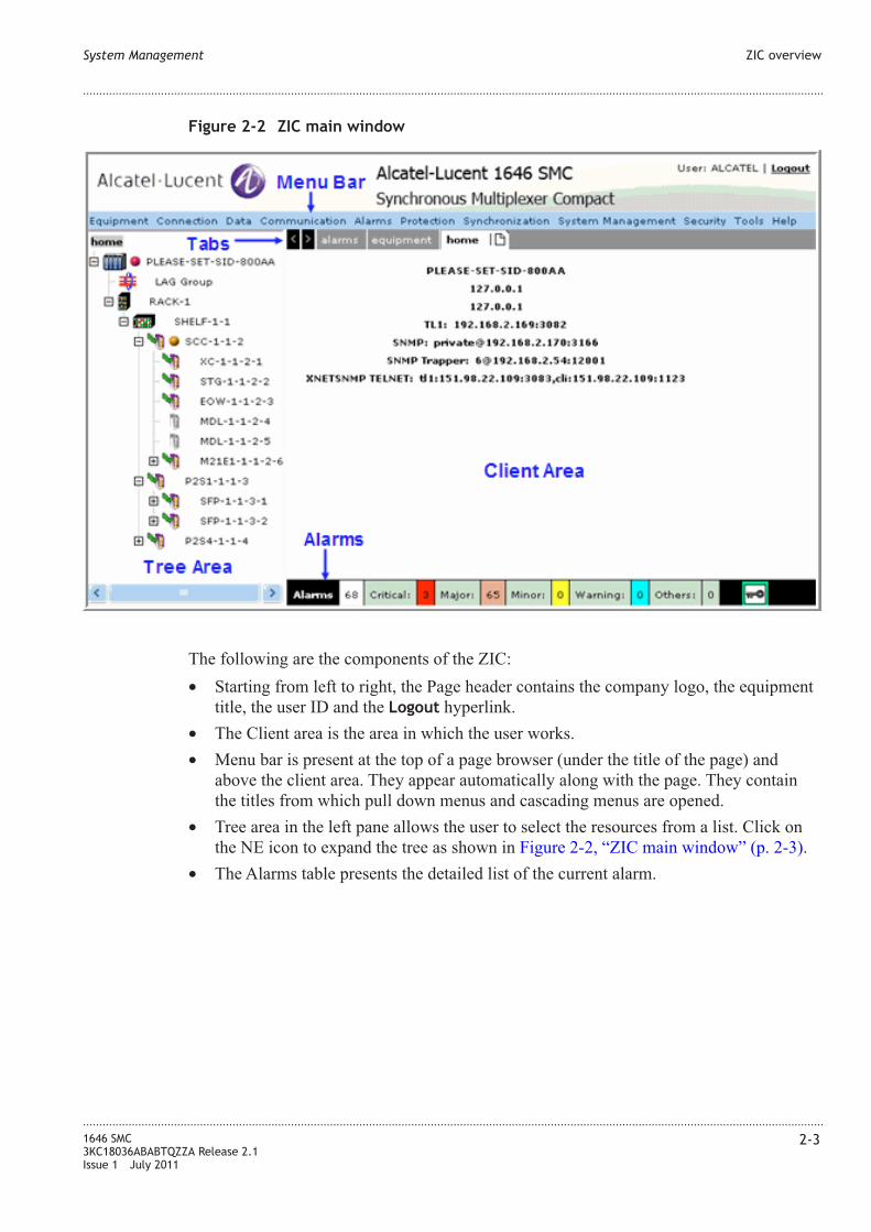
The following are the components of the ZIC:
• Starting from left to right, the Page header contains the company logo, the equipment
title, the user ID and the Logout hyperlink.
• The Client area is the area in which the user works.
• Menu bar is present at the top of a page browser (under the title of the page) and
above the client area. They appear automatically along with the page. They contain
the titles from which pull down menus and cascading menus are opened.
• Tree area in the left pane allows the user to select the resources from a list. Click on
the NE icon to expand the tree as shown in Figure 2-2, “ZIC main window” (p. 2-3).
• The Alarms table presents the detailed list of the current alarm.
Figure 2-2 ZIC main window
System Management ZIC overview
....................................................................................................................................................................................................................................
....................................................................................................................................................................................................................................
1646 SMC
3KC18036ABABTQZZA Release 2.1
Issue 1 July 2011
2-3

Procedure 2-1: Establish ZIC session
When to use
Use this procedure to establish a Zero Installation Craft (ZIC) terminal session.
...................................................................................................................................................................................................
1 If this is the first usage of ZIC, go to Step 2, otherwise, go to Step 3.
...................................................................................................................................................................................................
2 Start the Alcatel-Lucent ZIC Launcher. Add the NE's IP address as shown in the figure.
Figure 2-3 ZIC launcher
System Management Procedure 2-1: Establish ZIC session
....................................................................................................................................................................................................................................
....................................................................................................................................................................................................................................
2-4 1646 SMC
3KC18036ABABTQZZA Release 2.1
Issue 1 July 2011
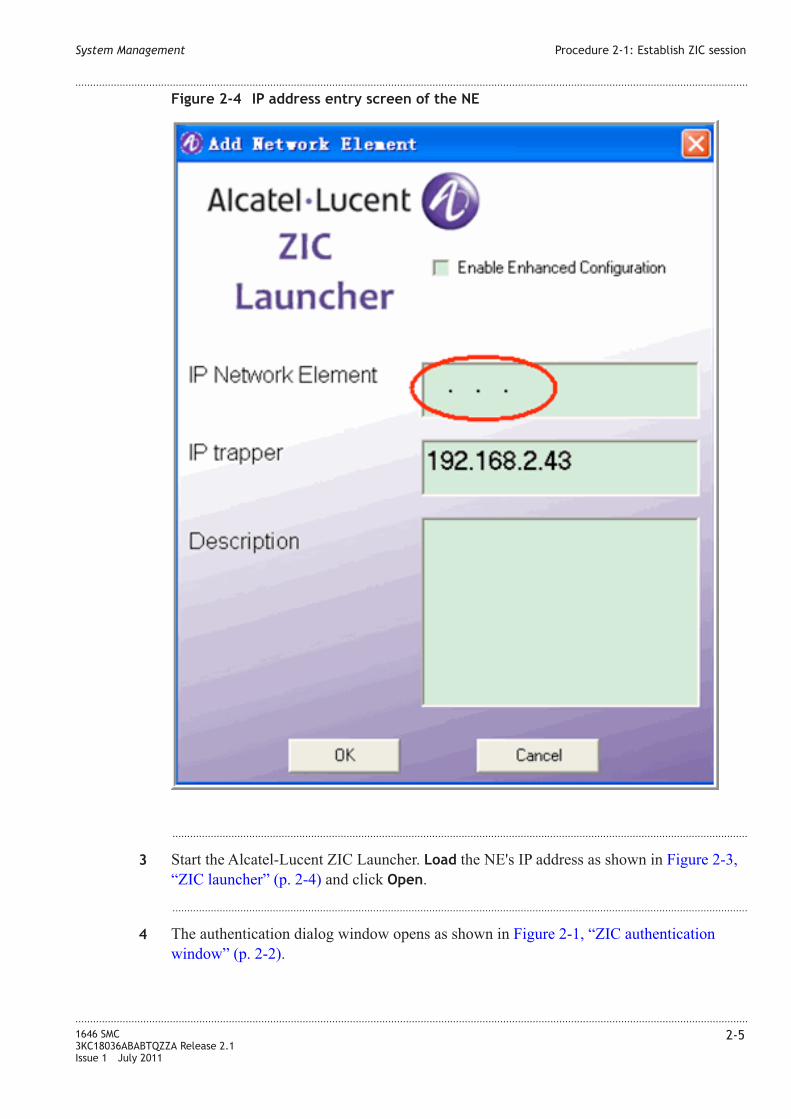
...................................................................................................................................................................................................
3 Start the Alcatel-Lucent ZIC Launcher. Load the NE's IP address as shown in Figure 2-3,
“ZIC launcher” (p. 2-4) and click Open.
...................................................................................................................................................................................................
4 The authentication dialog window opens as shown in Figure 2-1, “ZIC authentication
window” (p. 2-2).
Figure 2-4 IP address entry screen of the NE
System Management Procedure 2-1: Establish ZIC session
....................................................................................................................................................................................................................................
....................................................................................................................................................................................................................................
1646 SMC
3KC18036ABABTQZZA Release 2.1
Issue 1 July 2011
2-5
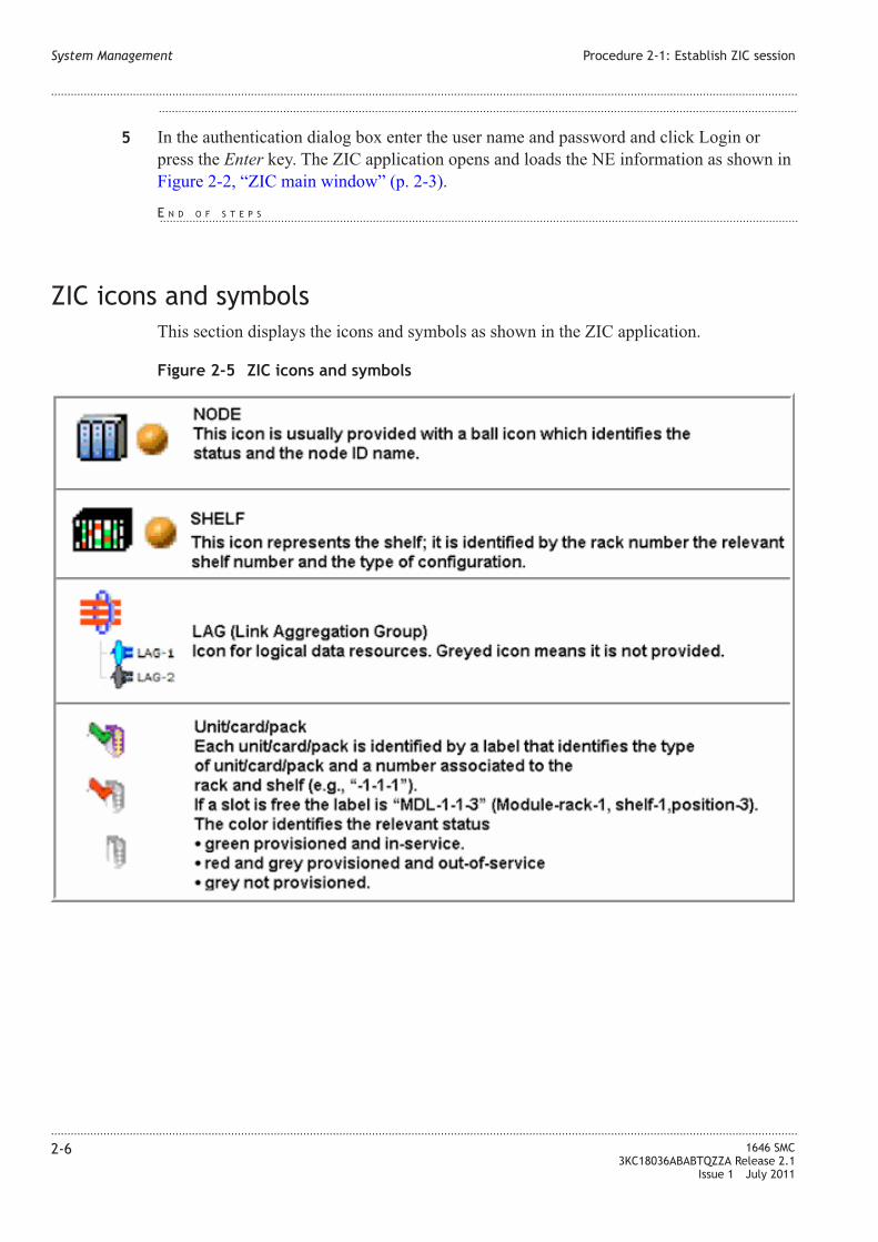
...................................................................................................................................................................................................
5 In the authentication dialog box enter the user name and password and click Login or
press the Enter key. The ZIC application opens and loads the NE information as shown in
Figure 2-2, “ZIC main window” (p. 2-3).
ZIC icons and symbols
This section displays the icons and symbols as shown in the ZIC application.
Figure 2-5 ZIC icons and symbols
System Management Procedure 2-1: Establish ZIC session
....................................................................................................................................................................................................................................
....................................................................................................................................................................................................................................
2-6 1646 SMC
3KC18036ABABTQZZA Release 2.1
Issue 1 July 2011
E N D O F S T E P S...................................................................................................................................................................................................

Menus
Description
This section describes an important aspect of the user interface. The user constantly has to
open Pages, select icons and navigate through the different functionalities of the Zero
Installation Craft (ZIC) terminal. A menu consists of a title, that usually identifies the
nature of the actions that can be undertaken, and a list of options associated with actions.
Menu types can be classified as:
• Menu bars
• Pull-down menus
• Cascading menus
• Pop-up menus
Menu bars
Menu bars present at the top of a page's browser (under the title of the page) and above
the client area. They appear automatically along with the page.
Pull down menu
A pull-down menu is pulled down from a menu item present in a menu bar. To open a
pull-down menu, click on the title of the menu you need to open with the "Select" mouse
button.
Note: A menu option followed by “...” means that selecting this option opens another
view. For example the Open... or Save As... menu options in the File pull-down
menu.
Cascading menus
Cascading menus are derived from pull-down menus and represent additional options for
the pull-down menu item selected. Cascading menus are indicated if the “>” sign follows
an option in a pull-down menu.
To open a cascading menu, click on the menu option with the “>” sign in the pull-down
menu.
System Management Menus
....................................................................................................................................................................................................................................
....................................................................................................................................................................................................................................
1646 SMC
3KC18036ABABTQZZA Release 2.1
Issue 1 July 2011
2-7

Equipment menu
This menu allows to manage the equipment configuration. The menu options are shown
in the following figure:
Connection menu
The connection menu allows to manage (provisioning, service type etc.) the client/line
traffic. The menu options are shown in the following figure:
• TDM Search - Allows to set the SDH service.
• TDM Create - Allows to configure the SDH service.
• ETS XC - Allows to set the Point-to-Point cross-connection services.
Figure 2-6 Equipment menu
Figure 2-7 Connection menu
System Management Equipment menu
....................................................................................................................................................................................................................................
....................................................................................................................................................................................................................................
2-8 1646 SMC
3KC18036ABABTQZZA Release 2.1
Issue 1 July 2011

Data menu
The data menu allows to set the service for Data traffic. The menu options are shown in
the following figure:
• Traffic descriptor - To set the operation mode.
• MAC Access Control List - To set the MAC Id.
• VLAN Profile - To set the virtual LAN mode.
• Color profile - To set the signal color policing.
• ASAP list - To show and manage the Alarm Severity Assignment Profile.
• Bridge - To create a bridge configuration.
• Queue Management - This allows management of the queue.
• OAM Management - This allows operation and maintenance management. The
suboptions are:
– Global Setting
– OAM Resource Config.
– Alarm Indication Signal
• EFM Tool - To manage EFM.
Figure 2-8 Data menu
System Management Data menu
....................................................................................................................................................................................................................................
....................................................................................................................................................................................................................................
1646 SMC
3KC18036ABABTQZZA Release 2.1
Issue 1 July 2011
2-9

Communication menu
The communication menu allows to configure and set the external communication for NE
management interfaces. The menu options are shown in the following figure:
• DCC - Allows to specifies the reference of DCC Channel (Line or Section).
• DCN Physical Interface - Allows to specify the supported Layer 3 (network layer) of
the OSI Data Communication Network (DCN).
• IP Tunnel - Allows the operator to manage an IP tunnel instance on the NE.
• Network Domain - Allows the operator to enter (add) a new static IP route in the IP
routing table, to instruct the NE to provide routing database information that is
supported by network layer of the OSI DCN, to retrieve a list of all immediate OSC
neighbors to the local network element and retrieve the parameters of a configured
OSIAREA that the NE is part of.
Alarms menu
The alarms menu allows to manage entities yield alarms when they malfunction. The
menu options are shown in the following figure:
Figure 2-9 Communication menu
Figure 2-10 Alarms menu
System Management Communication menu
....................................................................................................................................................................................................................................
....................................................................................................................................................................................................................................
2-10 1646 SMC
3KC18036ABABTQZZA Release 2.1
Issue 1 July 2011

• TCA Profile - Allows to configure and display of the active threshold crossing alarm
profile (TCA = Threshold Crossing Alarm).
• ASAP Mng - Allows to configure and display the ASAP (Alarm Severity Assignment
Profile).
• ALM CUTOFF - Allows to silence the office audible alarm indications.
• ALM Resynch. - Allows to update the alarm database to the current alarm situation.
• Condition Log - Allows to collect the alarm history report from the NE.
Protection menu
This menu allows the to manage the available protection systems. The menu options are
shown in the following figure:
Synchonization menu
This menu allows the operator to manage the ports dedicated to BITS (Building
Integrated Timing Source) facilities for clock distribution purposes. A BITS output
reference is a DS1 signal. The menu options are shown in the following figure:
Figure 2-11 Protection menu
Figure 2-12 Synchonization menu
System Management Alarms menu
....................................................................................................................................................................................................................................
....................................................................................................................................................................................................................................
1646 SMC
3KC18036ABABTQZZA Release 2.1
Issue 1 July 2011
2-11

System Management menu
This menu provides options for users and administrators to manage the system. The menu
options are shown in the following figure:
Security menu
This menu contains the following sub-menu options for user and administrative users.
Figure 2-13 System Management menu
Figure 2-14 Security menu
System Management System Management menu
....................................................................................................................................................................................................................................
....................................................................................................................................................................................................................................
2-12 1646 SMC
3KC18036ABABTQZZA Release 2.1
Issue 1 July 2011

Tools menu
This menu allows the operator to open a Telnet console for TL1 commands. The menu
options are shown in the following figure:
Help menu
The menu options are shown in the following figure:
Help menu allows the operator to obtain information about:
• About (software version)
• NE TL1 Syntax
Figure 2-15 Tools menu
System Management Tools menu
....................................................................................................................................................................................................................................
....................................................................................................................................................................................................................................
1646 SMC
3KC18036ABABTQZZA Release 2.1
Issue 1 July 2011
2-13

System Management Help menu
....................................................................................................................................................................................................................................
....................................................................................................................................................................................................................................
2-14 1646 SMC
3KC18036ABABTQZZA Release 2.1
Issue 1 July 2011

3 3Equipment management
Overview
Purpose
Use this chapter to perform equipment provisioning.
Contents
Procedure 3-1: Configure a board 3-1
Procedure 3-2: Configure a port 3-5
Procedure 3-3: Housekeeping support 3-12
Procedure 3-1: Configure a board
When to use
Use this procedure to configure a board.
Procedure
...................................................................................................................................................................................................
1 Select Rack xx → Shelf xx → Board xx from the tree area.
...................................................................................................................................................................................................................................
1646 SMC
3KC18036ABABTQZZA Release 2.1
Issue 1 July 2011
3-1

...................................................................................................................................................................................................
2 The following table provides description of the Rack xx > Shelf xx > Board xx
parameters.
Table 3-1 Board xx panel parameters
Parameter Description
Access Identifier Specifies the access identifier of the selected board
Current Provisioned
Type
Specifies the type of equipment to be provisioned
Alarm Profile Specifies the alarm profile.
Figure 3-1 Rack xx > Shelf xx > Board xx
Equipment management Procedure 3-1: Configure a board
....................................................................................................................................................................................................................................
....................................................................................................................................................................................................................................
3-2 1646 SMC
3KC18036ABABTQZZA Release 2.1
Issue 1 July 2011

...................................................................................................................................................................................................
3 The following table provides description of the Restart panel parameters.
Table 3-2 Board xx Restart panel parameters
Parameter Description
Access Identifier Specifies the access identifier of the selected board
Phase Specifies the reload of dynamic and static data (sw and db if
present). Processor is restarted. It is supported by all the
Processor-based Card without traffic affecting if the current
configuration is in line with the one to be reloaded.
For SCC card only COLD reset type is supported in R1.0
...................................................................................................................................................................................................
4 Click Save to save the settings on the page.
...................................................................................................................................................................................................
5 Click View to view the Alarms on the alarms panel.
Provision a module
...................................................................................................................................................................................................
1 Click Provision hyperlink to provision the SFP module for the selected board as shown in
Figure 3-1, “Rack xx > Shelf xx > Board xx” (p. 3-2).
...................................................................................................................................................................................................
2 The following screen appears for the module selected.
Equipment management Procedure 3-1: Configure a board
....................................................................................................................................................................................................................................
....................................................................................................................................................................................................................................
1646 SMC
3KC18036ABABTQZZA Release 2.1
Issue 1 July 2011
3-3
E N D O F S T E P S...................................................................................................................................................................................................

...................................................................................................................................................................................................
3 Select the SFP/XFP module from the Provisioned Type drop-down list box.
...................................................................................................................................................................................................
4 Click Save to save the settings, the tree area displays the XFP module provisioned on the
selected facility.
...................................................................................................................................................................................................
5 Click Remote Inventory to view the details of the selected module.
...................................................................................................................................................................................................
6 Click Save to save the settings.
...................................................................................................................................................................................................
7 Click View hyperlink displayed under Alarms and Conditions panel to view the
alarms/conditions raised by the equipment.
Figure 3-2 Rack xx > Shelf xx > Board xx > Module xx
Equipment management Procedure 3-1: Configure a board
....................................................................................................................................................................................................................................
....................................................................................................................................................................................................................................
3-4 1646 SMC
3KC18036ABABTQZZA Release 2.1
Issue 1 July 2011
E N D O F S T E P S...................................................................................................................................................................................................

Procedure 3-2: Configure a port
When to use
Use this procedure to configure a port.
Procedure
...................................................................................................................................................................................................
1 Select Rack xx → Shelf xx → Board xx → Module → Port from the tree area displays
the following tabs:
• Physical
• Bridge
• IGMP Snooping
• PM Data
Equipment management Procedure 3-2: Configure a port
....................................................................................................................................................................................................................................
....................................................................................................................................................................................................................................
1646 SMC
3KC18036ABABTQZZA Release 2.1
Issue 1 July 2011
3-5

Figure 3-3 Rack xx > Shelf xx > Board xx > Module xx > Port
Equipment management Procedure 3-2: Configure a port
....................................................................................................................................................................................................................................
....................................................................................................................................................................................................................................
3-6 1646 SMC
3KC18036ABABTQZZA Release 2.1
Issue 1 July 2011

...................................................................................................................................................................................................
2 The State panel allows to change the settings of the resource by means of the following
parameters:
Table 3-3 State panel parameters
Parameter Description
Port It specifies the identifier of the unit resource.
Administrative status The combo-box allows to set/change the unit
administrative state. The choices are: UP
(active state) or DOWN(not active state).
Last change The text field shows the date and time when
the resource had been managed last time.
Operational State The text field shows the actual state of the
resource.
Mau operational state The text field shows the actual state of the
Medium Access Unit (MAU).
Alarm Severity profile The text field shows the ASAP label that is in
use for the resource.
The panel has the following hyperlinks:
• Save which applies the previous selections
• Change severity profile.
...................................................................................................................................................................................................
3 The Ethernet port panel allows to change the settings of the resource by means of the
following parameters:
Parameter Description
Connector present It indicates if the interface has a physical
connector. The allowable values are: true or
false.
Type The text field indicates the type of port
Speed The text field indicates the actual configured
rate.
Alias The entry field indicates the friendly name for
the interface, set by the user.
Encapsulation mode The text field indicates the method of MAC
packets encapsulation inside the underlying
physical layer.
Equipment management Procedure 3-2: Configure a port
....................................................................................................................................................................................................................................
....................................................................................................................................................................................................................................
1646 SMC
3KC18036ABABTQZZA Release 2.1
Issue 1 July 2011
3-7

Parameter Description
Maximum MRU The entry field indicates the Maximum
Transmit Unit/Maximum Receive Unit size of
the largest packet which can be sent/received
on the interface, specified in octets.
Promiscous mode The text field indicates indicating whether this
interface has to inspect the packets' MAC
addresses. The allowable values are: true or
false.
FCS Discard Errored Frame The text field indicates the insertion or
removal of GFP-FCS (Frame Check
Sequence) field into the optional field pFCS of
the GFP frame. The allowable values are: true
or false.
Client type The text field indicates the transported layer.
Default Pause Behavior The combo-box allows to chose the pause
signal that is inserted for Flow Control
signalling. It applies only in the case that the
AutoNegotiation- AdminStatus is in disabled.
Possible values are: Asymmetric-Pause,
disabled.
Underlie Layer The text field indicates the associated layer.
The allowable value is: mau
Link up/down trap The text field indicates whether linkUp /
linkDown traps (notification upon the
changing of the node operational state from up
to down and vice versa) should be generated
for this interface. possible options: enabled /
disabled the associated layer. The allowable
values are: enabled or disabled.
Bridge tab menu
...................................................................................................................................................................................................
1 Click on Bridge tab menu.
Equipment management Procedure 3-2: Configure a port
....................................................................................................................................................................................................................................
....................................................................................................................................................................................................................................
3-8 1646 SMC
3KC18036ABABTQZZA Release 2.1
Issue 1 July 2011
E N D O F S T E P S...................................................................................................................................................................................................
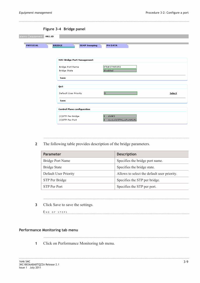
...................................................................................................................................................................................................
2 The following table provides description of the bridge parameters.
Parameter Description
Bridge Port Name Specifies the bridge port name.
Bridge State Specifies the bridge state.
Default User Priority Allows to select the default user priority.
STP Per Bridge Specifies the STP per bridge.
STP Per Port Specifies the STP per port.
...................................................................................................................................................................................................
3 Click Save to save the settings.
Performance Monitoring tab menu
...................................................................................................................................................................................................
1 Click on Performance Monitoring tab menu.
Figure 3-4 Bridge panel
Equipment management Procedure 3-2: Configure a port
....................................................................................................................................................................................................................................
....................................................................................................................................................................................................................................
1646 SMC
3KC18036ABABTQZZA Release 2.1
Issue 1 July 2011
3-9
E N D O F S T E P S...................................................................................................................................................................................................
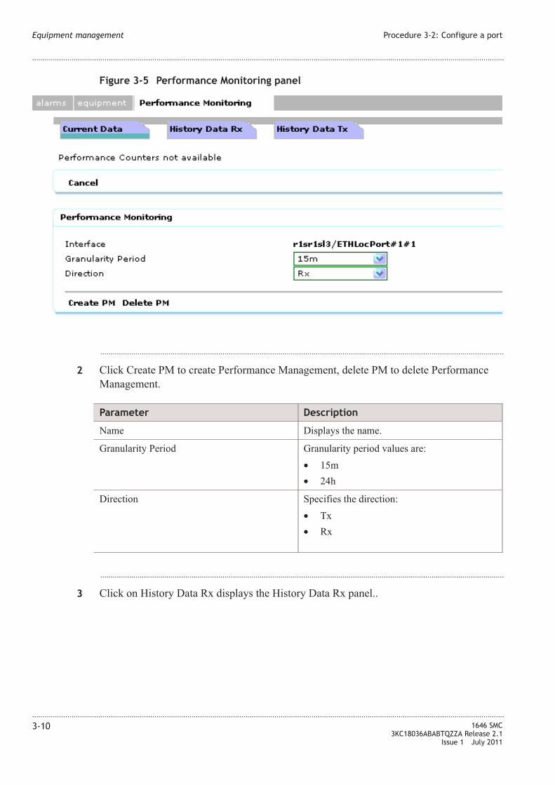
...................................................................................................................................................................................................
2 Click Create PM to create Performance Management, delete PM to delete Performance
Management.
Parameter Description
Name Displays the name.
Granularity Period Granularity period values are:
• 15m
• 24h
Direction Specifies the direction:
• Tx
• Rx
...................................................................................................................................................................................................
3 Click on History Data Rx displays the History Data Rx panel..
Figure 3-5 Performance Monitoring panel
Equipment management Procedure 3-2: Configure a port
....................................................................................................................................................................................................................................
....................................................................................................................................................................................................................................
3-10 1646 SMC
3KC18036ABABTQZZA Release 2.1
Issue 1 July 2011

...................................................................................................................................................................................................
4 The following table provides description of the History Data Rx parameters.
Parameter Description
Time Stamp Specifies the time.
EINB Ethernet Incoming Bytes
EINF Ethernet Incoming Frames
...................................................................................................................................................................................................
5 Click on History Data Rx displays the History Data Tx panel.
...................................................................................................................................................................................................
6 The following table provides description of the History Data Tx parameters.
Parameter Description
Time Stamp Specifies the time.
EONB Ethernet Outgoing Bytes
EONF Ethernet Outgoing Frames
Figure 3-6 History Data Rx panel
Figure 3-7 History Data Tx panel
Equipment management Procedure 3-2: Configure a port
....................................................................................................................................................................................................................................
....................................................................................................................................................................................................................................
1646 SMC
3KC18036ABABTQZZA Release 2.1
Issue 1 July 2011
3-11

Procedure 3-3: Housekeeping support
When to use
The NE will be able to receive and process three separate customer-defined inputs for
fault conditions arising externally to the NE. The fault conditions will be processed and
reported as for internally detected fault conditions.
It will be possible to disable the reporting from any input if not used. The inputs will be
capable of interfacing to a dry relay contact, i.e. an input will comprise two wire interface
capable of detecting an open or closed circuit condition between the two connections.
Each user alarm input shall be separately configurable to accept either a closed circuit or
open circuit state as the active alarm condition. The inputs from the dry contacts are
normally used for site specific alarms such as open door, high temperature, high water
level, etc. The polarity of an external input control determines the relationship between
the declaration of an environmental condition and the physical signal. The NE shall drive
1 separate output station controls for customer defined site specific facilities external to
the NE, such as air conditioning, generators, etc. Operating an external control means that
a relay is activated to control some external device. Releasing an external control means
deactivating the relay. The polarity of an external output control determines the
relationship between the control state (CONTSTATE) value and the physical signal.
Provisioning of housekeeping alarms and controls shall be persistent Customer access to
the Housekeeping (HKP) connections shall be via 25 pin D-Sub connector on the NE user
access panel.
Input Points
...................................................................................................................................................................................................
1 Select Housekeeping → Input Points.
Figure 3-8 Input Points shelf selection panel
Equipment management Procedure 3-2: Configure a port
....................................................................................................................................................................................................................................
....................................................................................................................................................................................................................................
3-12 1646 SMC
3KC18036ABABTQZZA Release 2.1
Issue 1 July 2011
E N D O F S T E P S...................................................................................................................................................................................................
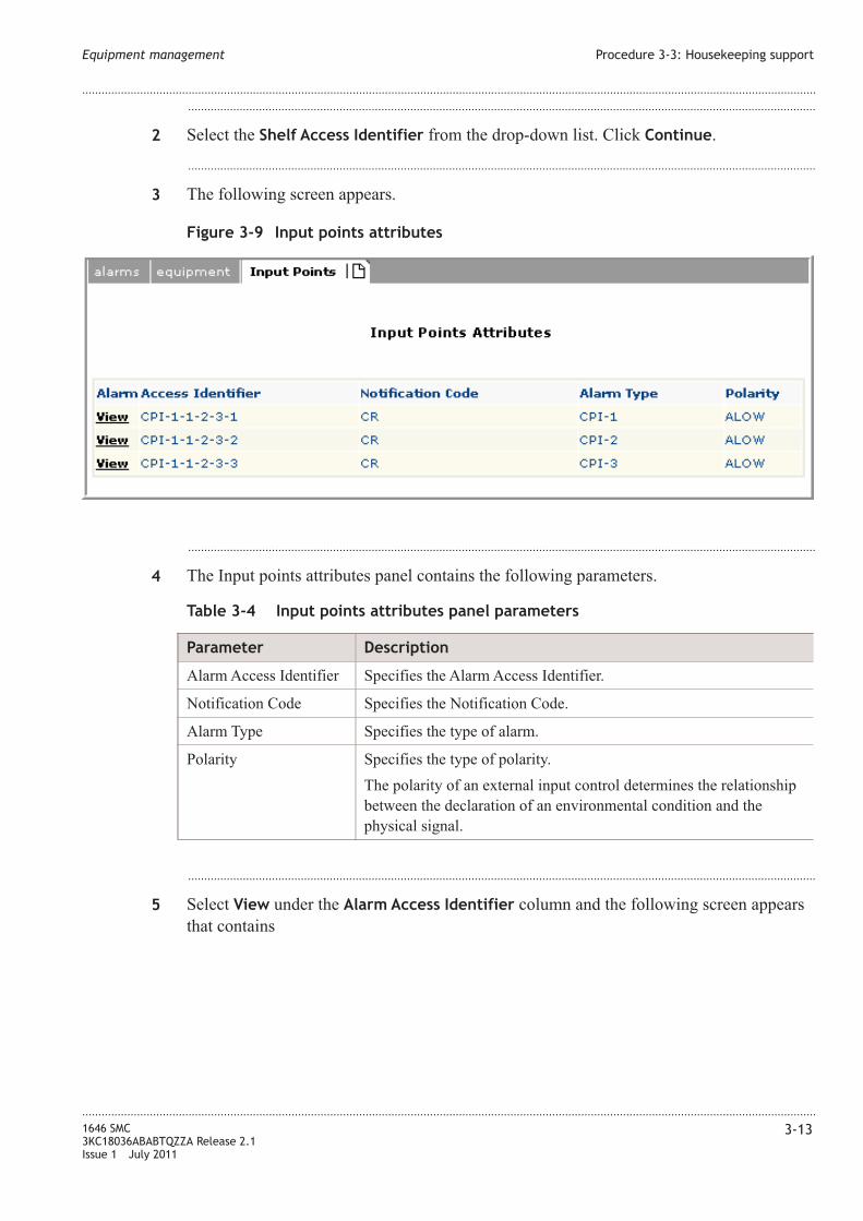
...................................................................................................................................................................................................
2 Select the Shelf Access Identifier from the drop-down list. Click Continue.
...................................................................................................................................................................................................
3 The following screen appears.
...................................................................................................................................................................................................
4 The Input points attributes panel contains the following parameters.
Table 3-4 Input points attributes panel parameters
Parameter Description
Alarm Access Identifier Specifies the Alarm Access Identifier.
Notification Code Specifies the Notification Code.
Alarm Type Specifies the type of alarm.
Polarity Specifies the type of polarity.
The polarity of an external input control determines the relationship
between the declaration of an environmental condition and the
physical signal.
...................................................................................................................................................................................................
5 Select View under the Alarm Access Identifier column and the following screen appears
that contains
Figure 3-9 Input points attributes
Equipment management Procedure 3-3: Housekeeping support
....................................................................................................................................................................................................................................
....................................................................................................................................................................................................................................
1646 SMC
3KC18036ABABTQZZA Release 2.1
Issue 1 July 2011
3-13

Figure 3-10 Alarms report
Equipment management Procedure 3-3: Housekeeping support
....................................................................................................................................................................................................................................
....................................................................................................................................................................................................................................
3-14 1646 SMC
3KC18036ABABTQZZA Release 2.1
Issue 1 July 2011
E N D O F S T E P S...................................................................................................................................................................................................

Output Points
...................................................................................................................................................................................................
1 Select Housekeeping → Output Points.
The Select Shelf panel appears.
...................................................................................................................................................................................................
2 Select the Shelf Access Identifier from the drop-down list. Click Continue.
...................................................................................................................................................................................................
3 The following screen appears.
...................................................................................................................................................................................................
4 Select the Access Identifier that requires the Action.
...................................................................................................................................................................................................
5 Click Release to release (deactivate) the External Control Output Points.
Releasing an external control means deactivating the relay.
...................................................................................................................................................................................................
6 Click Operate to operate (activate) the External Control Output Points.
Operating an external control means that a relay is activated to control some external
device.
Figure 3-11 Operate/Release Output Points
Equipment management Procedure 3-3: Housekeeping support
....................................................................................................................................................................................................................................
....................................................................................................................................................................................................................................
1646 SMC
3KC18036ABABTQZZA Release 2.1
Issue 1 July 2011
3-15
E N D O F S T E P S...................................................................................................................................................................................................

Equipment management Procedure 3-3: Housekeeping support
....................................................................................................................................................................................................................................
....................................................................................................................................................................................................................................
3-16 1646 SMC
3KC18036ABABTQZZA Release 2.1
Issue 1 July 2011
4 4Ethernet Functions
Overview
Purpose
Provides a description of the Ethernet functionality and features supported in the Zero
Installation Craft (ZIC) terminal.
Contents
Procedure 4-1: Traffic descriptor 4-2
Procedure 4-2: Resource Availability 4-5
Procedure 4-3: MAC Access Control List management 4-8
Procedure 4-4: VLAN Profile 4-10
Procedure 4-5: Create color profile 4-11
Procedure 4-6: Bridge configuration 4-13
Procedure 4-7: IGMP management 4-14
Procedure 4-8: Create ASAP list 4-16
Procedure 4-9: Global setting 4-18
Procedure 4-10: Create maintenance domain 4-19
Procedure 4-11: Create maintenance association 4-20
Procedure 4-12: Create MEP 4-23
Procedure 4-13: EFM tool 4-25
Procedure 4-14: Configure EFM tool 4-26
Procedure 4-15: Create VLAN 4-28
Procedure 4-16: ConfigureVLAN 4-29
Procedure 4-17: Dynamic filtering DB 4-30
Procedure 4-18: Configure static unicast filtering 4-31
Procedure 4-19: Configure static multicast filtering 4-32
Procedure 4-20: Ethernet P2P XC 4-34
...................................................................................................................................................................................................................................
1646 SMC
3KC18036ABABTQZZA Release 2.1
Issue 1 July 2011
4-1

Procedure 4-1: Traffic descriptor
When to use
This procedure is to be used as a guideline for a set of instructions to create, configure,
activate and delete a traffic descriptor.
A Traffic descriptor is the set of Committed Information Rate (CIR), Committed Burst
Size (CBS), Peak Information Rate (PIR), and Peak Burst Size (PBS) parameters used by
the System for bandwidth checks related to port bit rate or Virtual Transport bit rate on
which tunnels and pseudowires are defined. Main use is metering and policing operations.
Create traffic descriptor
Use this procedure to create traffic descriptor:
...................................................................................................................................................................................................
1 Select Data → Traffic descriptor. Click Create hyperlink.
Result: The Traffic Descriptor panel is displayed.
Table 4-1 Traffic descriptor panel parameters
Parameter Description
User Label Indicates the label for Traffic Descriptor.
Figure 4-1 Traffic descriptor panel
Ethernet Functions Procedure 4-1: Traffic descriptor
....................................................................................................................................................................................................................................
....................................................................................................................................................................................................................................
4-2 1646 SMC
3KC18036ABABTQZZA Release 2.1
Issue 1 July 2011

Table 4-1 Traffic descriptor panel parameters (continued)
Parameter Description
Service type Specifies the type of service the traffic. Identifies the used output queue.
Queue is specified by specifying the service type.
CIR [Kb/sec] Committed Information Rate - This is the maximum rate (kb/sec) with
high priority guaranteed for the Tunnel/Pseudowire packets delivery.
PIR [Kb/sec] Peak Information Rate - This is the maximum peak rate allowed (kb/sec)
for the Tunnel/Pseudowire.
CBS [KBytes] Committed Burst Size - This is the maximum burst size (byte) with high
priority guaranteed for the Tunnel/Pseudowire packets deliver.
PBS [KBytess] Peak Burst Size - This is the maximum burst rate allowed (byte) for the
Tunnel/Pseudowire.
Ethernet Functions Procedure 4-1: Traffic descriptor
....................................................................................................................................................................................................................................
....................................................................................................................................................................................................................................
1646 SMC
3KC18036ABABTQZZA Release 2.1
Issue 1 July 2011
4-3

...................................................................................................................................................................................................
2 The Traffic Descriptor tab displays the table that contains different traffic descriptor
entries.
Table 4-2 Service type parameters
Parameter Description
Service type Indicates the Traffic codification, according to international standard
conversion:
BestEffortService - serves Low priority traffic, which relies on transport
layer protocol to recover from loss and tolerates large delay; e.g. E-mail
and file transfer applications. Best Effort denotes BW (PIR > CIR = 0 in
100kbps increments), which may or may not be available per network
operator’s reservation for Best Effort policy. It may therefore be
unavailable under congestion conditions.
BackGroundService
RegulatedService - serves Medium priority traffic, which relies on
transport layer protocol to recover from occasional loss and requires
moderate delay; e.g. client–server applications. Regulated service
denotes BW (PIR > CIR >0 in 100Kbps increments), which may be
overbooked per network operator’s overbooking policy. The portion of
bandwidth between CIR and PIR (EIR) may therefore be partially
available under congestion conditions.
Grouped
RegulatedService1
RegulatedService3
RegulatedService4
GuaranteedService - serves High priority traffic for mission critical
applications that require loss–less delivery and minimal delay.
Guaranteed SLA denotes BW (CIR = PIR > 0 in 100Kbps increments),
that is always available regardless of any congestion conditions. Traffic
delivered using Guaranteed BW, is policed to the CIR value with a burst
window equal to the CBS.
GuaranteedService2
CIR [Kb/sec] This is the normal medium rate (expressed in kb/sec) of the data flow
(Effective Bandwidth) and it ranges from 0 to PIR value. It can be set
only if the RegulatedService has been selected; in BestEffortService
case it is set to 0 by the system; in GuaranteedService case it is set equal
to PIR value.
PIR [Kb/sec] This is the maximum rate (expressed in kb/sec) up to which the source
can transmit for a short time period and it ranges from 3 to
physical-linerate of the relative Port.
Ethernet Functions Procedure 4-1: Traffic descriptor
....................................................................................................................................................................................................................................
....................................................................................................................................................................................................................................
4-4 1646 SMC
3KC18036ABABTQZZA Release 2.1
Issue 1 July 2011
Table 4-2 Service type parameters (continued)
Parameter Description
CBS [Kbytes] This is the committed number of bytes for which the source may
transmit the PIR; it ranges from 0 to 64 MB. It can be set only if the
RegulatedService traffic has been selected; in BestEffortService case it
is set to 0 by the system; in GuaranteedService case it is set equal to PBS
value. A value greater than MTU (e.g. 2000) is advisable.
PBS [Kbytes] This is the number of bytes for which are allowed to be sent above PIR
or CIR before the colour (drop eligibility) of the packet changes; it
ranges from 1 to 64 MB (this max value cannot be greater than the
minimum value of 64 MB or 256xCBS. I.e.: if CBS=2000, then
PBS<512 kB). A value greater than MTU (e.g. 2000) is advisable.
...................................................................................................................................................................................................
3 TD Policing Mode contains a drop-down list containing the following options:
• td_undefined
• td_colorBlind
• td_colorAware
• td_colorAwareNoCoupling
• td_colorAwareWithCoupling
...................................................................................................................................................................................................
4 Click Cancel to return to the previous page.
...................................................................................................................................................................................................
5 Click Save & Exit to save all the changes and exit from the window.
...................................................................................................................................................................................................
6 Click Save & Continue to save the settings and create another traffic descriptor.
Procedure 4-2: Resource Availability
When to use
This procedure is used to monitor and to count the amount of dynamic NE resources,
where dynamic NE resources (for example, ETS Classifier, ETS Inflow, ETS Outflow
and so on..) are mapped inside NE internal resources.
Ethernet Functions Procedure 4-1: Traffic descriptor
....................................................................................................................................................................................................................................
....................................................................................................................................................................................................................................
1646 SMC
3KC18036ABABTQZZA Release 2.1
Issue 1 July 2011
4-5
E N D O F S T E P S...................................................................................................................................................................................................
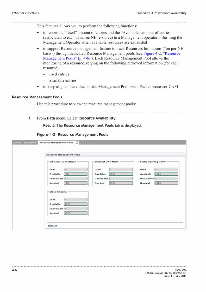
This features allows you to perform the following functions:
• to report the “Used” amount of entries and the “Available” amount of entries
(associated to each dynamic NE resource) to a Management operator, informing the
Management Operator when available resources are exhausted
• to support Resource management feature to track Resources limitations (“on per-NE
basis”) through dedicated Resource Management pools (see Figure 4-2, “Resource
Management Pools” (p. 4-6) ). Each Resource Management Pool allows the
monitoring of a resource, relying on the following retrieved information (for each
resource):
– used entries
– available entries
• to keep aligned the values inside Management Pools with Packet processor CAM
Resource Management Pools
Use this procedure to view the resource management pools:
...................................................................................................................................................................................................
1 From Data menu, Select Resource Availability.
Result: The Resource Management Pools tab is displayed.
Figure 4-2 Resource Management Pools
Ethernet Functions Procedure 4-2: Resource Availability
....................................................................................................................................................................................................................................
....................................................................................................................................................................................................................................
4-6 1646 SMC
3KC18036ABABTQZZA Release 2.1
Issue 1 July 2011

Resource Management Pool
Table 4-3 Resource Management Pool parameters
Parameter Description
ETS Cross-Connections
Used Specifies the Used number of entries for the NE resource ETS
Cross-Connections
Available Specifies the Available number of entries for the NE resource ETS
Cross-Connections.
Unavailable Specifies the Unavailable number of entries for the NE resource
ETS Cross-Connections.
Nominal Specifies the nominal number of entries for the NE resource ETS
Cross-Connections.
Ethernet OAM MEPs
Used Specifies the Used number of entries for the NE resource Ethernet
OAM MEPs.
Available Specifies the Available number of entries for the NE resource
Ethernet OAM MEPs.
Unavailable Specifies the Unavailable number of entries for the NE resource
Ethernet OAM MEPs.
Nominal Specifies the nominal number of entries for the NE resource
Ethernet OAM MEPs.
Static Vlan Reg. Entry
Used Specifies the Used number of entries for the NE resource static
VLAN.
Available Specifies the Available number of entries for the NE resource static
VLAN.
Unavailable Specifies the Unavailable number of entries for the NE resource
static VLAN.
Nominal Specifies the nominal number of entries for the NE resource static
VLAN.
Static Filtering
Used Specifies the Used number of entries for the NE resource static
filtering.
Available Specifies the Available number of entries for the NE resource static
filtering.
Unavailable Specifies the Unavailable number of entries for the NE resource
static filtering.
Nominal Specifies the nominal number of entries for the NE resource static
filtering.
Ethernet Functions Procedure 4-2: Resource Availability
....................................................................................................................................................................................................................................
....................................................................................................................................................................................................................................
1646 SMC
3KC18036ABABTQZZA Release 2.1
Issue 1 July 2011
4-7
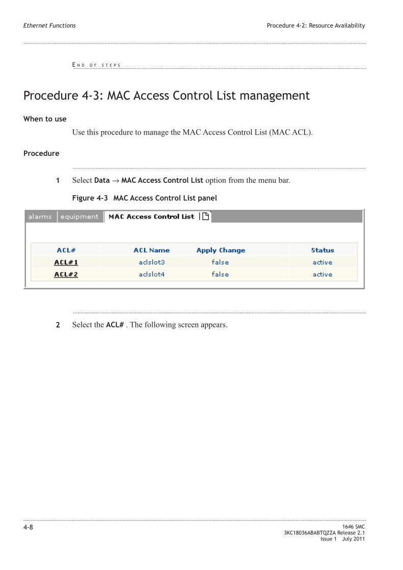
Procedure 4-3: MAC Access Control List management
When to use
Use this procedure to manage the MAC Access Control List (MAC ACL).
Procedure
...................................................................................................................................................................................................
1 Select Data → MAC Access Control List option from the menu bar.
...................................................................................................................................................................................................
2 Select the ACL# . The following screen appears.
Figure 4-3 MAC Access Control List panel
Ethernet Functions Procedure 4-2: Resource Availability
....................................................................................................................................................................................................................................
....................................................................................................................................................................................................................................
4-8 1646 SMC
3KC18036ABABTQZZA Release 2.1
Issue 1 July 2011
E N D O F S T E P S...................................................................................................................................................................................................

...................................................................................................................................................................................................
3
Table 4-4 Modify MAC Access Control panel parameters
Parameter Description
ACL Identifier Specifies the selected ACL Identifier.
ACL Name Allows to enter the ACL Name
Apply Change Allows to select the change to the ACL. Values are: true or false.
Status Specifies the status.
...................................................................................................................................................................................................
4 Management Access Control Element (ACE) panel contains to View hyperlink. Click
View to Search the Management ACE.
Figure 4-4 Modify MAC Access Control panel
Ethernet Functions Procedure 4-3: MAC Access Control List management
....................................................................................................................................................................................................................................
....................................................................................................................................................................................................................................
1646 SMC
3KC18036ABABTQZZA Release 2.1
Issue 1 July 2011
4-9

...................................................................................................................................................................................................
5 Management Actual Access Control Element (ACE) panel contains to View hyperlink.
Click View to Search the Management ACE.
...................................................................................................................................................................................................
6 Click Search to find a Management ACE.
...................................................................................................................................................................................................
7 Click Cancel to cancel the settings on the page and return to previous page.
Procedure 4-4: VLAN Profile
When to use
The virtual LAN (VLAN) management provides reports the registered VLANs associated
to the Ethernet interface existing on the each data card and in specific range. VLAN
registration is not applicable to MAC Bridge case.
User this procedure to set the virtual LAN mode.
Procedure
...................................................................................................................................................................................................
1 Select Data → VLAN profile option from the menu bar.
Figure 4-5 Management Access Control Element (ACE) panel
Ethernet Functions Procedure 4-3: MAC Access Control List management
....................................................................................................................................................................................................................................
....................................................................................................................................................................................................................................
4-10 1646 SMC
3KC18036ABABTQZZA Release 2.1
Issue 1 July 2011
E N D O F S T E P S...................................................................................................................................................................................................

...................................................................................................................................................................................................
2
Table 4-5 VLAN Protocol Profile panel parameters
Parameter Description
User Label Allows to digit a mnemonic string to address the VLAN. Click on the
entry box.
Ethernet Type (0x) Allows to digit an hexadecimal value for the provider protocol-type (PT)
that is inserted into the 2-bytes field of the Stacked-VLAN shim header;
the value identifies the network provider and has to be 2-bytes long in
hexadecimal notation; the third non-included byte is forced by default to
“0x”. The PT is used to recognize the type of afferent VLAN frames, i.e.
if they are “S-Vlan-tagged” or others; by default, an hex value of 88A8
is interpreted as SVlan tagged. Frames with PT value different than this
is treated as non S-Vlan-tagged. An hex value of 8100 is interpreted as
Q-Vlan tagged. Other values of PT are interpreted as generic
Stacked-Vlan frames, used to interwork among different network
providers
...................................................................................................................................................................................................
3 Click Cancel to cancel the operation and return to the previous page.
...................................................................................................................................................................................................
4 Click Save & continue to apply the changes and continue the configuration process.
...................................................................................................................................................................................................
5 Click Save & Exit to apply the changes and the following page appears.
Procedure 4-5: Create color profile
Figure 4-6 VLAN Profile
Ethernet Functions Procedure 4-4: VLAN Profile
....................................................................................................................................................................................................................................
....................................................................................................................................................................................................................................
1646 SMC
3KC18036ABABTQZZA Release 2.1
Issue 1 July 2011
4-11
E N D O F S T E P S...................................................................................................................................................................................................

When to use
Use this procedure to create a new color profile.
Procedure
...................................................................................................................................................................................................
1 Select Data → Color profile option from the menu bar.
...................................................................................................................................................................................................
2 Click Create hyperlink.
The following screen appears.
...................................................................................................................................................................................................
3
Table 4-6 Color Profile panel parameters
Parameter Description
Color Profile Mode Specifies the color profile mode.
The values are
• Priority
• Dscp
User Label Specifies the label for the new color profile
Figure 4-7 Color profile
Ethernet Functions Procedure 4-5: Create color profile
....................................................................................................................................................................................................................................
....................................................................................................................................................................................................................................
4-12 1646 SMC
3KC18036ABABTQZZA Release 2.1
Issue 1 July 2011

Table 4-6 Color Profile panel parameters (continued)
Parameter Description
Priority Bits 0 to 7 Specifies the priority bits. The valid range is 0-7.
The values are
• green
• red
• yellow
...................................................................................................................................................................................................
4 Select Dscp from the Color Profile Mode drop-down list. The Priority bits increases to 0-
63.
...................................................................................................................................................................................................
5 Click Cancel to unsave the settings and return to the previous page.
...................................................................................................................................................................................................
6 Click Save & Exit to save the settings and return to the previous page.
...................................................................................................................................................................................................
7 Click Save & Continue to save the settings and continue to create another color profile.
Procedure 4-6: Bridge configuration
When to use
User this procedure to create a new bridge configuration.
...................................................................................................................................................................................................
1 Select Data → Bridge → Configuration option from the menu bar.
Ethernet Functions Procedure 4-5: Create color profile
....................................................................................................................................................................................................................................
....................................................................................................................................................................................................................................
1646 SMC
3KC18036ABABTQZZA Release 2.1
Issue 1 July 2011
4-13
E N D O F S T E P S...................................................................................................................................................................................................
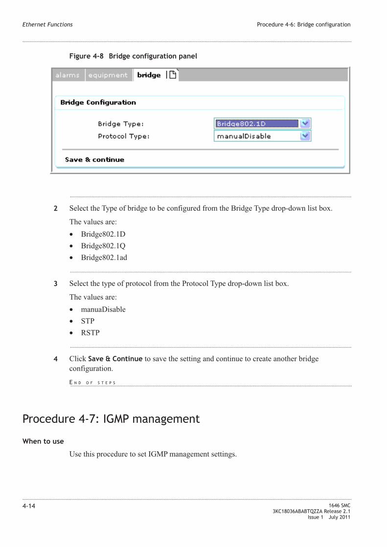
...................................................................................................................................................................................................
2 Select the Type of bridge to be configured from the Bridge Type drop-down list box.
The values are:
• Bridge802.1D
• Bridge802.1Q
• Bridge802.1ad
...................................................................................................................................................................................................
3 Select the type of protocol from the Protocol Type drop-down list box.
The values are:
• manuaDisable
• STP
• RSTP
...................................................................................................................................................................................................
4 Click Save & Continue to save the setting and continue to create another bridge
configuration.
Procedure 4-7: IGMP management
When to use
Use this procedure to set IGMP management settings.
Figure 4-8 Bridge configuration panel
Ethernet Functions Procedure 4-6: Bridge configuration
....................................................................................................................................................................................................................................
....................................................................................................................................................................................................................................
4-14 1646 SMC
3KC18036ABABTQZZA Release 2.1
Issue 1 July 2011
E N D O F S T E P S...................................................................................................................................................................................................

Procedure
...................................................................................................................................................................................................
1 Select Data → IGMP Management option from the menu bar.
Result: The IGMP Management per NE tab is displayed
...................................................................................................................................................................................................
2 The IGMP Management per NE displays the details of Board, Router Neighbor Timeouts
and their status.
Click Create link to configure IGMP management for a new board.
Result: The IGMP Configurations per NE panel is displayed
...................................................................................................................................................................................................
3 Click Select link to choose the board for IGMP configuration is done.
Result: A new window is displayed with a list of boards.
Ethernet Functions Procedure 4-7: IGMP management
....................................................................................................................................................................................................................................
....................................................................................................................................................................................................................................
1646 SMC
3KC18036ABABTQZZA Release 2.1
Issue 1 July 2011
4-15
E N D O F S T E P S...................................................................................................................................................................................................

Procedure 4-8: Create ASAP list
When to use
Use this procedure to configure a new ASAP list.
Procedure
...................................................................................................................................................................................................
1 Select Data → ASAP list option from the menu bar.
...................................................................................................................................................................................................
2 Select Show ghost objects to activate the ghost objects.
...................................................................................................................................................................................................
3 Select Create to configure a new ASAP list.
Figure 4-9 ASAP window
Figure 4-10 Create new ASAP
Ethernet Functions Procedure 4-8: Create ASAP list
....................................................................................................................................................................................................................................
....................................................................................................................................................................................................................................
4-16 1646 SMC
3KC18036ABABTQZZA Release 2.1
Issue 1 July 2011

...................................................................................................................................................................................................
4 Enter the new Asap Label in the entry box and click Create as shown in the following
figure.
...................................................................................................................................................................................................
5
Table 4-7 ASAP panel parameters
Parameter Description
Asap User Label Specifies the Asap name
Alarm type Specifies the type of alarm.
SA - Severity in
service affecting
case
Specifies the alarm severity levels in case of affecting the service. The
values are:
• critical
• major
• minor
• warning
• intermediate
Figure 4-11 New ASAP
Ethernet Functions Procedure 4-8: Create ASAP list
....................................................................................................................................................................................................................................
....................................................................................................................................................................................................................................
1646 SMC
3KC18036ABABTQZZA Release 2.1
Issue 1 July 2011
4-17

Table 4-7 ASAP panel parameters (continued)
Parameter Description
NSA - Severity in
non service affecting
case
Specifies the alarm severity levels in case of non service affecting case.
The values are:
• critical
• major
• minor
• warning
• intermediate
...................................................................................................................................................................................................
6 Click Save Asap Label to the save the settings.
...................................................................................................................................................................................................
7 Click Save or add severity row for adding a new severity row.
...................................................................................................................................................................................................
8 Click Cancel to return to the previous page.
Procedure 4-9: Global setting
When to use
Use this procedure to set OAM - Global Configuration.
Procedure
...................................................................................................................................................................................................
1 Select Data → OAM management → Global Setting option from the menu bar.
...................................................................................................................................................................................................
2 The NE Global Setting tab displays the OAM Global Configuration panel.
This panel contains the following parameters:
• ETH Type
• LBM Time Out [sec]
Ethernet Functions Procedure 4-8: Create ASAP list
....................................................................................................................................................................................................................................
....................................................................................................................................................................................................................................
4-18 1646 SMC
3KC18036ABABTQZZA Release 2.1
Issue 1 July 2011
E N D O F S T E P S...................................................................................................................................................................................................
E N D O F S T E P S...................................................................................................................................................................................................

Procedure 4-10: Create maintenance domain
When to use
Use this procedure to configure the maintenance domain.
Procedure
...................................................................................................................................................................................................
1 Select Data → OAM Management → OAM Resource config. → MD option from the
menu bar.
Click Create hyperlink.
Result: The Create Maintenance Domain panel is displayed.
This panel lists the parameters described in the following table:
Table 4-8 Maintenance Domain panel parameters
Parameter Description
MD Label Specifies the maintenance domain label. The default values is MD#0
Name Specifies the name for the maintenance domain
MHFCreation Indicates the MIP Half Function (MHF) Creation.
The values are:
• defMHFnone
• defMHFdefault
Format Specifies the MD format.
The values are:
• charString
• dnsLikeName
• none
Figure 4-12 Create Maintenance Domain panel
Ethernet Functions Procedure 4-10: Create maintenance domain
....................................................................................................................................................................................................................................
....................................................................................................................................................................................................................................
1646 SMC
3KC18036ABABTQZZA Release 2.1
Issue 1 July 2011
4-19

Table 4-8 Maintenance Domain panel parameters (continued)
Parameter Description
Level Specifies the maintenance domain levels. The valid range is from Level0
to Level7
Status Specifies the maintenance domain status. The values are:
• up
• down
...................................................................................................................................................................................................
2 Click Save to save the settings and return to the previous panel.
...................................................................................................................................................................................................
3 Click Cancel to cancel the settings and return to the previous panel.
Procedure 4-11: Create maintenance association
When to use
Use this procedure to configure the maintenance association.
Procedure
...................................................................................................................................................................................................
1 Select Data → OAM Management → OAM Resource config. → MA option from the
menu bar.
Ethernet Functions Procedure 4-10: Create maintenance domain
....................................................................................................................................................................................................................................
....................................................................................................................................................................................................................................
4-20 1646 SMC
3KC18036ABABTQZZA Release 2.1
Issue 1 July 2011
E N D O F S T E P S...................................................................................................................................................................................................

Result: The Maintenance Associations Range panel is displayed.
This panel lists the parameters described in the following table:
Table 4-9 Maintenance Domain panel parameters
Parameter Description
Search Filter Specifies the search criteria. The values are show all or specify criteria
MD From To Specifies the MD range from 1-4
MA From To Specifies the MA range from 1-80
...................................................................................................................................................................................................
2 Click Search/Refresh to filter the Maintenance Association based on the range selected.
...................................................................................................................................................................................................
3 Click Create to configure a new Maintenance Association.
Figure 4-13 Maintenance Associations Range panel
Ethernet Functions Procedure 4-11: Create maintenance association
....................................................................................................................................................................................................................................
....................................................................................................................................................................................................................................
1646 SMC
3KC18036ABABTQZZA Release 2.1
Issue 1 July 2011
4-21

Result: The Create Maintenance Association panel is displayed.
This panel lists the parameters described in the following table:
Table 4-10 Create Maintenance Association panel parameters
Parameter Description
MD Specifies the MD number.
Status Specifies the maintenance domain status. The values are:
• up
• down
MA Index Specifies the index for new Maintenance Association.
MHFCreation The values are:
• defMHFnone
• defMHFdefault
MA Name Specifies the new name for Maintenance Association.
CCM Interval The values are:
• interval100ms
• interval1s
• interval10s
• interval1min
• interval10min
Format Specifies the format for new Maintenance Association. The values are:
• charString
Type Type is vid
Vid Click on Select to choose the Vid.
Figure 4-14 Create Maintenance Association panel
Ethernet Functions Procedure 4-11: Create maintenance association
....................................................................................................................................................................................................................................
....................................................................................................................................................................................................................................
4-22 1646 SMC
3KC18036ABABTQZZA Release 2.1
Issue 1 July 2011

...................................................................................................................................................................................................
4 Click Cancel to cancel the settings and return to the previous panel.
...................................................................................................................................................................................................
5 Click Save to save the settings and return to the previous panel.
Procedure 4-12: Create MEP
When to use
Use this procedure to configure a new MEP.
Procedure
...................................................................................................................................................................................................
1 Select Data → OAM Management → OAM Resource config. → MA MEP list option from
the menu bar.
Result: The Maintenance Associations Range panel is displayed.
This panel lists the parameters described in the following table:
Table 4-11 Maintenance Domain panel parameters
Parameter Description
Search Filter Specifies the search criteria. The values are Show all or Specify
Criteria.
Figure 4-15 MA MEP List Range panel
Ethernet Functions Procedure 4-11: Create maintenance association
....................................................................................................................................................................................................................................
....................................................................................................................................................................................................................................
1646 SMC
3KC18036ABABTQZZA Release 2.1
Issue 1 July 2011
4-23
E N D O F S T E P S...................................................................................................................................................................................................

Table 4-11 Maintenance Domain panel parameters (continued)
Parameter Description
MD From To Specifies the MD range from 1-4
MA From To Specifies the MA range from 1-80
MEP From To Specifies the MEP range from 1-8190
...................................................................................................................................................................................................
2 Select the filter criteria from the Search Filter drop-down list box. The values are: Show
alland specify criteria.
...................................................................................................................................................................................................
3 If Show all is selected as a search filter the MD From and To and MA From and To range
cannot be set by the user. To set the specified range, select specify criteria and click
Search that displays the existing MA MEP list.
...................................................................................................................................................................................................
4 Click Search to filter the MEP based on the range selected.
...................................................................................................................................................................................................
5 Select Data → OAM Management → OAM Resource config. → MEP option from the
menu bar.
Click Create hyperlink.
This panel lists the parameters described in the following table:
Table 4-12 Create MEP panel parameters
Parameter Description
MA Label Specifies the MA label for the MEP
MEP Identifier Specifies the MEP identifier for the MEP
If Index Specifies the If Index value for the MEP
Figure 4-16 Create MEP panel
Ethernet Functions Procedure 4-12: Create MEP
....................................................................................................................................................................................................................................
....................................................................................................................................................................................................................................
4-24 1646 SMC
3KC18036ABABTQZZA Release 2.1
Issue 1 July 2011

Table 4-12 Create MEP panel parameters (continued)
Parameter Description
LTM/CCM Priority
(0..7)
Specifies the LTM priority. The valid range is 0-7
LBM Priority Specifies the LBM priority. The default value is 7
CCIEnable Specifies the CCIEnable as either True or False
Active Indicates the Activation State. The values are:
• true
• false
Direction Indicates the MEP Direction. The values are:
• Up
• Down
...................................................................................................................................................................................................
6 Click Select to choose the MA Label, MEP Identifier and If index values and click Save
to store the settings.
...................................................................................................................................................................................................
7 Click Cancel to revoke all the settings and return to the previous panel
Procedure 4-13: EFM tool
When to use
Use this procedure to search for the available local ports.
Procedure
...................................................................................................................................................................................................
1 Select Data → EFM tool option from the menu bar.
Ethernet Functions Procedure 4-12: Create MEP
....................................................................................................................................................................................................................................
....................................................................................................................................................................................................................................
1646 SMC
3KC18036ABABTQZZA Release 2.1
Issue 1 July 2011
4-25
E N D O F S T E P S...................................................................................................................................................................................................

Result: The EFM tool tab displays the Search Local Port panel.
...................................................................................................................................................................................................
2 Click Search link to search for the available ports.
Result: The boards panel is displayed.
...................................................................................................................................................................................................
3 Click boards link on the left pane.
Result: The list of local ports available are displayed in the right pane.
...................................................................................................................................................................................................
4 Click on any of the available port link to select that port.
Result: The selected port name is displayed in the Search Local Port panel.
...................................................................................................................................................................................................
5 Click Show.
Result: The EFM Tool panel with Configuration and Link Monitoring tabs is
displayed.
Procedure 4-14: Configure EFM tool
When to use
Use this procedure to configure the available local ports.
Procedure
...................................................................................................................................................................................................
1 Select Data → EFM tool option from the menu bar.
Figure 4-17 EFM tool
Ethernet Functions Procedure 4-13: EFM tool
....................................................................................................................................................................................................................................
....................................................................................................................................................................................................................................
4-26 1646 SMC
3KC18036ABABTQZZA Release 2.1
Issue 1 July 2011
E N D O F S T E P S...................................................................................................................................................................................................

Result: The EFM tool panel is displayed with the Configuration and Link Monitoring
tabs. By default the Configuration tab is opened.
...................................................................................................................................................................................................
2 Selectenabled to enable the Admin State.
Result: The boards panel is displayed.
...................................................................................................................................................................................................
3 Click Save on the bottom left pane of the panel to save the changes.
...................................................................................................................................................................................................
4 Click Cancel to undo the changes and return back to the Search Local Port panel.
...................................................................................................................................................................................................
5 Click Show.
Figure 4-18 EFM tool
Ethernet Functions Procedure 4-14: Configure EFM tool
....................................................................................................................................................................................................................................
....................................................................................................................................................................................................................................
1646 SMC
3KC18036ABABTQZZA Release 2.1
Issue 1 July 2011
4-27

Result: The EFM Tool panel with Configuration and Link Monitoring tabs is
displayed.
Procedure 4-15: Create VLAN
When to use
Use this procedure to search, create and configure VLAN.
Procedure
...................................................................................................................................................................................................
1 Select Data → Virtual LAN Management → Virtual LAN option from the menu bar.
Result: The VLAN Registration tab is displayed
...................................................................................................................................................................................................
2 Enter the range of ports to be searched in From: and To: boxes and click Search.
Result: The search result is displayed.
...................................................................................................................................................................................................
3 Click Create link on the bottom left pane of the VLAN Registration tab.
Result: The Create VLAN panel is displayed.
...................................................................................................................................................................................................
4 Enter a numeric value in the VLAN Id: text box. Then select the port to which you want to
assign the VLAN Id from the list of ports in Available Port panel and by clicking
.
Figure 4-19 VLAN Registration
Ethernet Functions Procedure 4-14: Configure EFM tool
....................................................................................................................................................................................................................................
....................................................................................................................................................................................................................................
4-28 1646 SMC
3KC18036ABABTQZZA Release 2.1
Issue 1 July 2011
E N D O F S T E P S...................................................................................................................................................................................................

Result: The selected port is displayed in the Selected Port: panel.
...................................................................................................................................................................................................
5 Click Save to save the VLAN created
Procedure 4-16: ConfigureVLAN
When to use
Use this procedure to configure VLAN.
Procedure
...................................................................................................................................................................................................
1 Select Data → Virtual LAN Management → Virtual LAN option from the menu bar.
Result: The VLAN Registration tab is displayed
...................................................................................................................................................................................................
2 Enter the range of ports to be searched in From: and To: boxes and click Search.
Result: The search result is displayed.
Figure 4-20 VLAN Registration
Ethernet Functions Procedure 4-15: Create VLAN
....................................................................................................................................................................................................................................
....................................................................................................................................................................................................................................
1646 SMC
3KC18036ABABTQZZA Release 2.1
Issue 1 July 2011
4-29
E N D O F S T E P S...................................................................................................................................................................................................

...................................................................................................................................................................................................
3 Select the check box of the VLAN that you want to configure and click Configure link
given for the selected VLAN.
Result: The Modify VLAN panel is displayed.
This panel lists the parameters described in the following table:
Table 4-13 Modify VLAN parameters
Parameter Description
VLAN Specifies the VLAN Id assigned.
Limit in learning
process
Indicates the status. The values are:
• disabled
• enabled
Port# Specifies the Port#
Value Specifies the Value
Untagged Specifies the Untagged ports
...................................................................................................................................................................................................
4 Click Save to save the VLAN modified.
...................................................................................................................................................................................................
5 Click Cancel to undo the changes and return back to VLAN Registration panel.
Procedure 4-17: Dynamic filtering DB
When to use
Use this procedure to view modify the dynamic filtering parameter.
Figure 4-21 Modify VLAN
Ethernet Functions Procedure 4-16: ConfigureVLAN
....................................................................................................................................................................................................................................
....................................................................................................................................................................................................................................
4-30 1646 SMC
3KC18036ABABTQZZA Release 2.1
Issue 1 July 2011
E N D O F S T E P S...................................................................................................................................................................................................
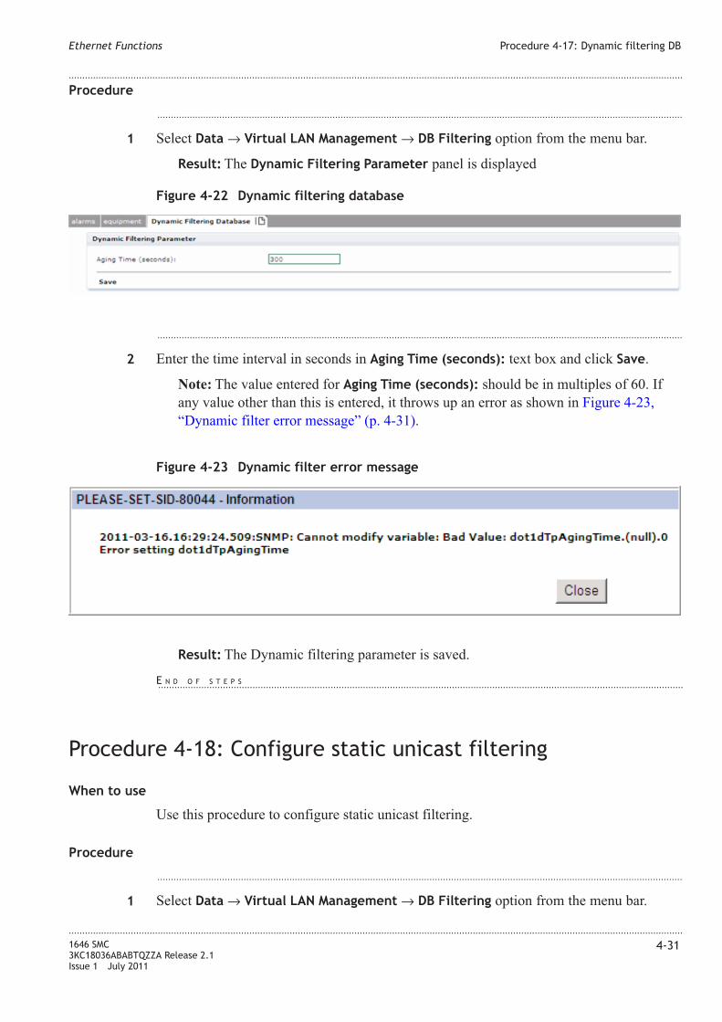
Procedure
...................................................................................................................................................................................................
1 Select Data → Virtual LAN Management → DB Filtering option from the menu bar.
Result: The Dynamic Filtering Parameter panel is displayed
...................................................................................................................................................................................................
2 Enter the time interval in seconds in Aging Time (seconds): text box and click Save.
Note: The value entered for Aging Time (seconds): should be in multiples of 60. If
any value other than this is entered, it throws up an error as shown in Figure 4-23,
“Dynamic filter error message” (p. 4-31).
Result: The Dynamic filtering parameter is saved.
Procedure 4-18: Configure static unicast filtering
When to use
Use this procedure to configure static unicast filtering.
Procedure
...................................................................................................................................................................................................
1 Select Data → Virtual LAN Management → DB Filtering option from the menu bar.
Figure 4-22 Dynamic filtering database
Figure 4-23 Dynamic filter error message
Ethernet Functions Procedure 4-17: Dynamic filtering DB
....................................................................................................................................................................................................................................
....................................................................................................................................................................................................................................
1646 SMC
3KC18036ABABTQZZA Release 2.1
Issue 1 July 2011
4-31
E N D O F S T E P S...................................................................................................................................................................................................

Result: The Static Unicast Filtering tab is displayed
...................................................................................................................................................................................................
2 Click Create link to configure a new static unicast filtering entry. .
Result: The Static Unicast Filtering Entry tab is displayed.
Table 4-14 Static Unicast Filtering Entry parameters
Parameters Description
VLAN ID Specifies the Virtual LAN ID of the equipment.
MAC Address Specifies the MAC address of the port.
Outbound port Specifies the outbound port of the equipment.
...................................................................................................................................................................................................
3 Click on the Select link to choose an existing VLAN ID from the drop-down list.
...................................................................................................................................................................................................
4 Click on the Select link to choose an existing outbound data ports from the drop-down
list.
...................................................................................................................................................................................................
5 Click Save & Exit to save the settings and return to the previous window.
...................................................................................................................................................................................................
6 Click Save & Continue to save the setting and configure another unicast entry.
...................................................................................................................................................................................................
7 Click Cancel to cancel the settings and return back to previous window.
Procedure 4-19: Configure static multicast filtering
When to use
Use this procedure to configure static multicast filtering.
Figure 4-24 Static Unicast Filtering
Ethernet Functions Procedure 4-18: Configure static unicast filtering
....................................................................................................................................................................................................................................
....................................................................................................................................................................................................................................
4-32 1646 SMC
3KC18036ABABTQZZA Release 2.1
Issue 1 July 2011
E N D O F S T E P S...................................................................................................................................................................................................

Procedure
...................................................................................................................................................................................................
1 Select Data → Virtual LAN Management → DB Filtering option from the menu bar.
Result: The Static Multicast Filtering tab is displayed
...................................................................................................................................................................................................
2 Click Create link to configure a new static multicast filtering entry. .
Result: The Static Multicast Filtering Entry tab is displayed.
Table 4-15 Static Multicast Filtering Entry parameters
Parameters Description
VLAN ID Specifies the Virtual LAN ID of the equipment.
MAC Address Specifies the MAC address of the port.
Outbound port Specifies the outbound port of the equipment.
...................................................................................................................................................................................................
3 Click on the Select link to choose an existing VLAN ID from the drop-down list.
...................................................................................................................................................................................................
4 Click on the Select link to choose an existing outbound data ports from the drop-down
list.
...................................................................................................................................................................................................
5 Click Save & Exit to save the settings and return to the previous window.
...................................................................................................................................................................................................
6 Click Save & Continue to save the setting and configure another multicast entry.
...................................................................................................................................................................................................
7 Click Cancel to cancel the settings and return back to previous window.
Figure 4-25 Static Multicast Filtering
Ethernet Functions Procedure 4-19: Configure static multicast filtering
....................................................................................................................................................................................................................................
....................................................................................................................................................................................................................................
1646 SMC
3KC18036ABABTQZZA Release 2.1
Issue 1 July 2011
4-33
E N D O F S T E P S...................................................................................................................................................................................................

Procedure 4-20: Ethernet P2P XC
When to use
Use this procedure to manage the P2P cross-connection.
Procedure
...................................................................................................................................................................................................
1 Select Connection → ETS → XC P2P option from the menu bar.
...................................................................................................................................................................................................
2 The P2P panel provides the cross-connection search criteria range.
...................................................................................................................................................................................................
3 Click Search to find a service instance defined in the specified range.
...................................................................................................................................................................................................
4 Click Create to create a new P2P instance. The following screen appears.
Figure 4-26 P2P Panel
Ethernet Functions Procedure 4-20: Ethernet P2P XC
....................................................................................................................................................................................................................................
....................................................................................................................................................................................................................................
4-34 1646 SMC
3KC18036ABABTQZZA Release 2.1
Issue 1 July 2011

This panel lists the parameters described in the following table:
Table 4-16 P2P data connection panel parameters
Parameter Description
Type Specifies the type of P2P service
From Allows to select the source point
To Allows to select the end point
Service Label Allows to enter a service label string
...................................................................................................................................................................................................
5 Click Cancel to cancel all the settings and return to the previous window.
...................................................................................................................................................................................................
6 Click Save & Exit to save the settings and exit from the window.
...................................................................................................................................................................................................
7 Click Save & Continue to save the settings and configure another P2P instance.
Figure 4-27 P2P data connection panel
Ethernet Functions Procedure 4-20: Ethernet P2P XC
....................................................................................................................................................................................................................................
....................................................................................................................................................................................................................................
1646 SMC
3KC18036ABABTQZZA Release 2.1
Issue 1 July 2011
4-35
E N D O F S T E P S...................................................................................................................................................................................................

Ethernet Functions Procedure 4-20: Ethernet P2P XC
....................................................................................................................................................................................................................................
....................................................................................................................................................................................................................................
4-36 1646 SMC
3KC18036ABABTQZZA Release 2.1
Issue 1 July 2011
5 5Synchronization
Overview
Purpose
Provides an overview of the chapter contents and an introduction to Time and Alarm
Synchronization.
Contents
Synchronization menu 5-1
Procedure 5-1: Modify BITS-0 5-2
Procedure 5-2: Modify BITS-OUT 5-3
Procedure 5-3: Administer system timing BITS 5-5
Synchronization outgoing 5-12
Synchronization menu
This menu allows the operator to manage the ports dedicated to BITS (Building
Integrated Timing Source) facilities for clock distribution purposes. A BITS output
reference is a DS1 signal.
The menu options are:
• BITS - Allows to modify the characteristics (BITS-0 as Primary and BITS-1 as
Secondary) and the outgoing port of reference clock.
• Synchronization - Allows to modify the parameters of the synchronization system.
• Synch. Outgoing - Allows to modify the parameters of the synchronization outgoing.
...................................................................................................................................................................................................................................
1646 SMC
3KC18036ABABTQZZA Release 2.1
Issue 1 July 2011
5-1

Procedure 5-1: Modify BITS-0
When to use
Use this procedure to edit bit 0 related to a given shelf.
Procedure
...................................................................................................................................................................................................
1 Select Synchronization → Bits → Modify BITS 0. The following panel appears.
...................................................................................................................................................................................................
2 Select the Shelf Access Identifier from the drop-down list.
...................................................................................................................................................................................................
3 Click Continue to continue with the operation.
...................................................................................................................................................................................................
4 The following screen appears.
Figure 5-1 BITS Select shelf panel
Synchronization Procedure 5-1: Modify BITS-0
....................................................................................................................................................................................................................................
....................................................................................................................................................................................................................................
5-2 1646 SMC
3KC18036ABABTQZZA Release 2.1
Issue 1 July 2011

The Modify BITS panel contains the following fields:
• Access Identifier - Specifies the access identifier for the selected BITS
• Signal Format - Specifies the signal format. The values are 2MHZ, or 2MBIT-SSM
• SA Bit Location - Specifies the SA bit location used to carry the SSM information.
The values are SA4, SA5, SA6, SA7, and SA8. The default menu value is the
previous existing value. If the existing value is empty. The default existing value is
SA4.
• SSM Supported - Specifies whether the timing input port supports SSM or not. The
values are Y and N.
...................................................................................................................................................................................................
5 The Save link is used to send the related command to the Network Element.
Automatically the Modify BITS page is loaded to show updated data.
...................................................................................................................................................................................................
6 A further panel Alarms allows to display the alarms relevant to the BITS. Click View
hyperlink to view the alarms.
Procedure 5-2: Modify BITS-OUT
When to use
Use this procedure to edit to search and edit bit out related to a given shelf
Figure 5-2 Modify BITS 0
Synchronization Procedure 5-1: Modify BITS-0
....................................................................................................................................................................................................................................
....................................................................................................................................................................................................................................
1646 SMC
3KC18036ABABTQZZA Release 2.1
Issue 1 July 2011
5-3
E N D O F S T E P S...................................................................................................................................................................................................
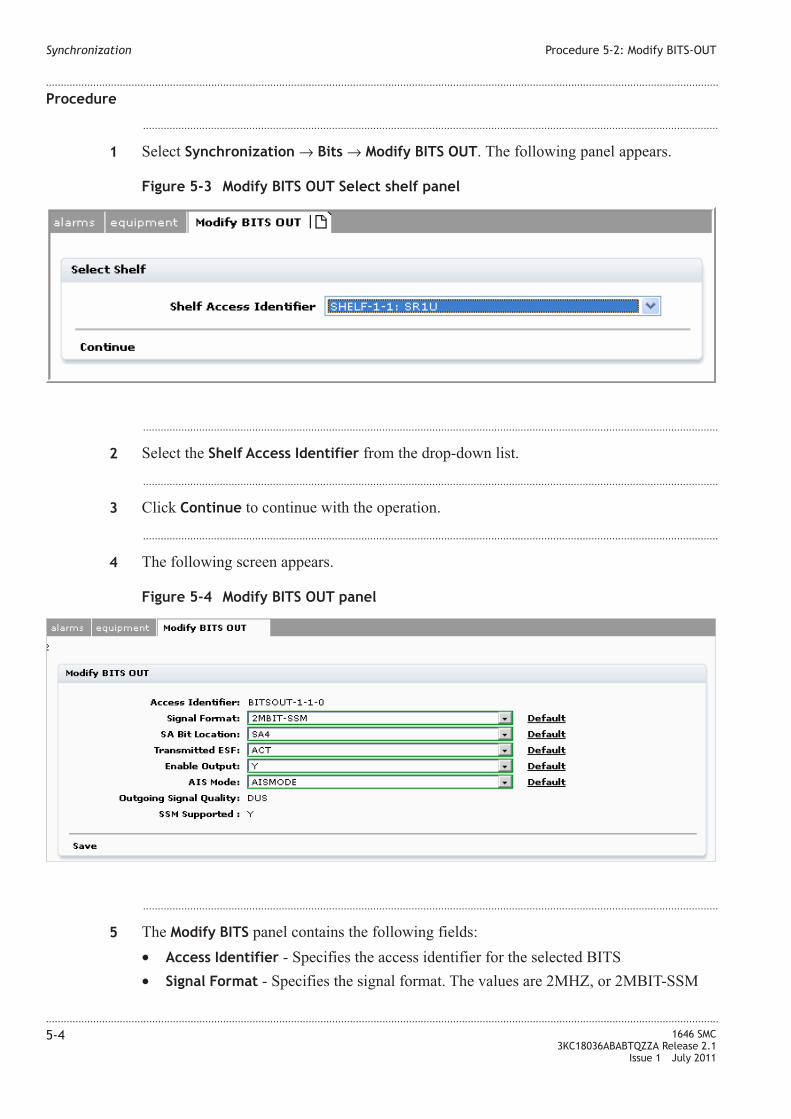
Procedure
...................................................................................................................................................................................................
1 Select Synchronization → Bits → Modify BITS OUT. The following panel appears.
...................................................................................................................................................................................................
2 Select the Shelf Access Identifier from the drop-down list.
...................................................................................................................................................................................................
3 Click Continue to continue with the operation.
...................................................................................................................................................................................................
4 The following screen appears.
...................................................................................................................................................................................................
5 The Modify BITS panel contains the following fields:
• Access Identifier - Specifies the access identifier for the selected BITS
• Signal Format - Specifies the signal format. The values are 2MHZ, or 2MBIT-SSM
Figure 5-3 Modify BITS OUT Select shelf panel
Figure 5-4 Modify BITS OUT panel
Synchronization Procedure 5-2: Modify BITS-OUT
....................................................................................................................................................................................................................................
....................................................................................................................................................................................................................................
5-4 1646 SMC
3KC18036ABABTQZZA Release 2.1
Issue 1 July 2011

• SA Bit Location- Specifies the SA bit location used to carry the SSM information. The
values are SA4, SA5, SA6, SA7, and SA8. The default menu value is the previous
existing value. If the existing value is empty. The default existing value is SA4.
• Transmitted ESF - Specifies if the output signal is the DUS message or is the actual
SSM value. The values are DUS and ACT. The default value is the previous existing
value. If the existing value is empty. The default existing value is DUS.
• Enable Output - Specifies the output mode to which the facility is set. The values are
Y and N. The default value is N.
• AIS Mode - Specifies which signal is inserted for the timing output port if the output
signal is squelched. The values are AISMODE and QLMODE. The default values is
the previous value. If the existing value is empty, the default factory value is
QLMODE.
• Outgoing Signal Quality - Specifies the quality value level for the out-going signal at
the timing output port. The values are PRC, SSUL, SSUT, SEC, and DUS.
• SA Bit Location - Specifies the SA bit location used to carry the SSM information.
The values are SA4, SA5, SA6, SA7, and SA8. The default menu value is the
previous existing value. If the existing value is empty. The default existing value is
SA4.
• SSM Supported - Specifies whether the timing input port supports SSM or not. The
values are Y and N.
...................................................................................................................................................................................................
6 Click Save that is used to send the related command to the Network Element.
Automatically the Modify BITS OUT page is loaded to show updated data.
Procedure 5-3: Administer system timing BITS
When to use
Use this procedure to retrieve, edit, remove, and restore Building Integrated Timing
Source (BITS) timing and to switch system clock synchronization from one reference to
the other.
General
Time Division Multiplexing (TDM) ports provides external synchronization from a
network timing source to the system. Under normal conditions, all terminating and
outgoing STMn’s have identical average frequency derived from the network timing
source.
The Network Element (NE) utilizes external Building Integrated Timing Supply (BITS)
timing to synchronize the system. BITS timing signal enters the system either directly via
the backplane (Rear Access Shelf) or via dedicated front plane integral, a panel just below
the fan.
Synchronization Procedure 5-2: Modify BITS-OUT
....................................................................................................................................................................................................................................
....................................................................................................................................................................................................................................
1646 SMC
3KC18036ABABTQZZA Release 2.1
Issue 1 July 2011
5-5
E N D O F S T E P S...................................................................................................................................................................................................

The following clock modes are supported:
• Locked mode (normal mode) - Steady state, the SETG generated clock signal is
controlled by the selected external timing reference determined by the T0 selection
process
• Holdover mode - Steady state. The operating condition of a clock that has lost its
references and is using data previously acquired (when it was operating in the normal
mode) to control its output signal.
• Free-running mode - Temporary operating mode. The operating condition when the
output signal is totally internally controlled with no influence of a present or previous
reference.
Procedure
...................................................................................................................................................................................................
1 Select Synchronization → Synchronization → Search. The following panel appears.
...................................................................................................................................................................................................
2 Select the access identifier from the Access Identifier drop-down list.
The values are:
• ALL
• SYNC
• EXTREF
• LINEREFSYS
...................................................................................................................................................................................................
3 Click Search to retrieve the synchronization timing BITS.
Figure 5-5 Synchronization panel
Synchronization Procedure 5-3: Administer system timing BITS
....................................................................................................................................................................................................................................
....................................................................................................................................................................................................................................
5-6 1646 SMC
3KC18036ABABTQZZA Release 2.1
Issue 1 July 2011
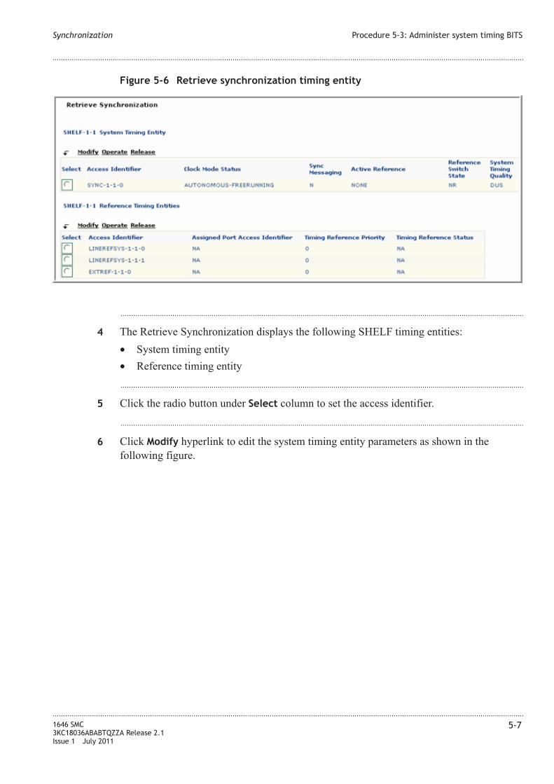
...................................................................................................................................................................................................
4 The Retrieve Synchronization displays the following SHELF timing entities:
• System timing entity
• Reference timing entity
...................................................................................................................................................................................................
5 Click the radio button under Select column to set the access identifier.
...................................................................................................................................................................................................
6 Click Modify hyperlink to edit the system timing entity parameters as shown in the
following figure.
Figure 5-6 Retrieve synchronization timing entity
Synchronization Procedure 5-3: Administer system timing BITS
....................................................................................................................................................................................................................................
....................................................................................................................................................................................................................................
1646 SMC
3KC18036ABABTQZZA Release 2.1
Issue 1 July 2011
5-7

...................................................................................................................................................................................................
7 The Access Identifier displays the system timing entity selected.
...................................................................................................................................................................................................
8 Set the Sync Messaging to either Y or N. Click Default to choose the default setting.
...................................................................................................................................................................................................
9 Click View to view the alarm profile for the selected timing entity from the Alarms panel.
...................................................................................................................................................................................................
10 Click Save to set the synchronization settings for the system timing entity and return to
the Synchronization window.
...................................................................................................................................................................................................
11 Click Operate or Release hyperlinks to perform the operate and release functions on
either system timing or references timing entities.
Operate
...................................................................................................................................................................................................
1 Select Synchronization → Synchronization → Operate. The following panel appears.
Figure 5-7 Modify Synchronization panel
Synchronization Procedure 5-3: Administer system timing BITS
....................................................................................................................................................................................................................................
....................................................................................................................................................................................................................................
5-8 1646 SMC
3KC18036ABABTQZZA Release 2.1
Issue 1 July 2011
E N D O F S T E P S...................................................................................................................................................................................................

...................................................................................................................................................................................................
2 The Synchronization Switch Outgoing tab displays the Modify Synchronization Switch
panel that contains the following parameters:
• Switch Command - Specifies the switch command that is requested by the user. The
values are LOCKOUT, FRCD, MAN, and INIT.
• Shelf Access Identifier - This is used to change the content of Switch To Reference
parameter according to the selected shelf access identifier
• Switch To Reference - Specifies the access identifier of the synchronization facility
...................................................................................................................................................................................................
3 Click Operate to send the command to the agent.
Release
...................................................................................................................................................................................................
1 Select Synchronization → Synchronization → Release. The following panel appears.
Figure 5-8 Operate - Modify synchronization switch
Synchronization Procedure 5-3: Administer system timing BITS
....................................................................................................................................................................................................................................
....................................................................................................................................................................................................................................
1646 SMC
3KC18036ABABTQZZA Release 2.1
Issue 1 July 2011
5-9
E N D O F S T E P S...................................................................................................................................................................................................

...................................................................................................................................................................................................
2 The Synchronization Switch Outgoing tab displays the Modify Synchronization Switch
panel that contains the following parameters:
• Switch Command - Specifies the switch command that is requested by the user. The
values are CLOCKSWITCH and REFSWITCH
• Shelf Access Identifier - This is used to change the content of Switch To Reference
parameter according to the selected shelf access identifier
• Access Identifier
The values are:
– SYNC
– EXTREF
– LINEREFSYS
...................................................................................................................................................................................................
3 Click Release to send the TL1 command to the agent.
Retrieve Synchronization Message
...................................................................................................................................................................................................
1 Select Synchronization → Synchronization → Sync. message. The following panel
appears.
Figure 5-9 Release - Modify synchronization switch
Synchronization Procedure 5-3: Administer system timing BITS
....................................................................................................................................................................................................................................
....................................................................................................................................................................................................................................
5-10 1646 SMC
3KC18036ABABTQZZA Release 2.1
Issue 1 July 2011
E N D O F S T E P S...................................................................................................................................................................................................

...................................................................................................................................................................................................
2 The Synchronization Message tab displays the Retrieve Synchronization Message
panel that displays the following parameters:
• Shelf Access Identifier - This is used to change the access identifier according to the
selected shelf identifier
• Access Identifier - Specifies the access identifier of the synchronization facility
...................................................................................................................................................................................................
3 The Search link sends the TL1 command to the agent and results are displayed in the
following Synchronization Message Search page.
Figure 5-10 Retrieve Synchronization Message panel
Figure 5-11 Search synchronization message results
Synchronization Procedure 5-3: Administer system timing BITS
....................................................................................................................................................................................................................................
....................................................................................................................................................................................................................................
1646 SMC
3KC18036ABABTQZZA Release 2.1
Issue 1 July 2011
5-11

...................................................................................................................................................................................................
4 The Retrieve Synchronization Message table contains the following columns:
• Access Identifier - Specifies the timing entity facility
• Incoming SSM Message - Specifies the actual quality value for the incoming SSM
derived from corresponding OH byte value of a timing reference.
Synchronization outgoing
This option contains the following sub-menu options:
• Search - To retrieve and edit outgoing synchronization resources related to a given
shelf
• Operate - To operate switching outgoing synchronization resources related to a given
shelf
• Release - To release switching outgoing sychronization resources related to a given
shelf
Search
...................................................................................................................................................................................................
1 Select Synchronization → Synch. Outgoing → Search. The following panel appears.
...................................................................................................................................................................................................
2 The Synchronization Outgoing tab displays the Synchronization Outgoing panel that
contains the following parameters:
• Shelf Access Identifier - This is used to change the content of Access Identifier
parameter according to the selected shelf
• Access Identifier - Specifies the access identifier of the synchronization facility
Figure 5-12 Synchronization Outgoing Search
Synchronization Procedure 5-3: Administer system timing BITS
....................................................................................................................................................................................................................................
....................................................................................................................................................................................................................................
5-12 1646 SMC
3KC18036ABABTQZZA Release 2.1
Issue 1 July 2011
E N D O F S T E P S...................................................................................................................................................................................................

...................................................................................................................................................................................................
3 Click Search to retrieve the shelf information based on the selection.
Operate
...................................................................................................................................................................................................
1 Select Synchronization → Synch. Outgoing → Operate. The following panel appears.
...................................................................................................................................................................................................
2 The Synchronization Switch Outgoing tab displays the Modify Synchronization Switch
Outgoing panel that contains the following parameters:
• Switch Command - Specifies the switch command that is requested by the user. The
values are LOCKOUT, FRCD, and MAN
• Shelf Access Identifier - This is used to change the content of Switch To Reference
parameter according to the selected shelf access identifier
• Switch To Reference - Specifies the access identifier of the synchronization facility
...................................................................................................................................................................................................
3 The Operate link sends the TL1 command to the agent.
Release
...................................................................................................................................................................................................
1 Select Synchronization → Synch. Outgoing → Release. The following panel appears.
Figure 5-13 Modify Synchronization Switch Outgoing Operate
Synchronization Synchronization outgoing
....................................................................................................................................................................................................................................
....................................................................................................................................................................................................................................
1646 SMC
3KC18036ABABTQZZA Release 2.1
Issue 1 July 2011
5-13
E N D O F S T E P S...................................................................................................................................................................................................
E N D O F S T E P S...................................................................................................................................................................................................
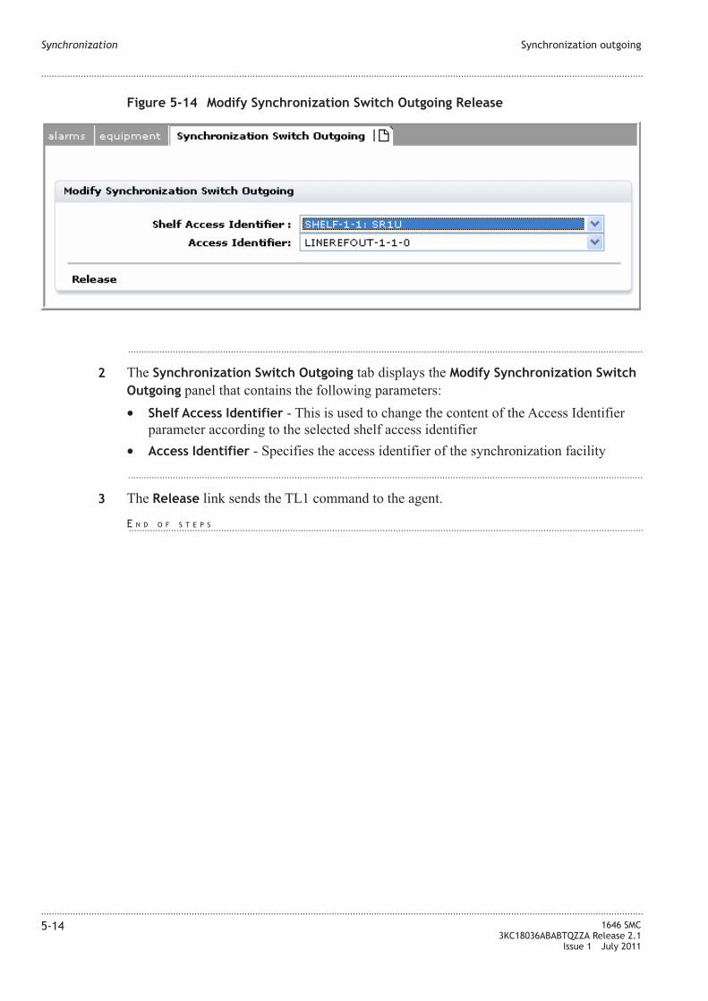
...................................................................................................................................................................................................
2 The Synchronization Switch Outgoing tab displays the Modify Synchronization Switch
Outgoing panel that contains the following parameters:
• Shelf Access Identifier - This is used to change the content of the Access Identifier
parameter according to the selected shelf access identifier
• Access Identifier - Specifies the access identifier of the synchronization facility
...................................................................................................................................................................................................
3 The Release link sends the TL1 command to the agent.
Figure 5-14 Modify Synchronization Switch Outgoing Release
Synchronization Synchronization outgoing
....................................................................................................................................................................................................................................
....................................................................................................................................................................................................................................
5-14 1646 SMC
3KC18036ABABTQZZA Release 2.1
Issue 1 July 2011
E N D O F S T E P S...................................................................................................................................................................................................

6 6Alarm Management
Overview
Purpose
supports different types of alarms and events in various scenarios related to the equipment
and transmission.
This section defines the alarms or events supported on the network element. The probable
cause, raise/clear criteria, object against which alarm is raised, alarm domain, and
consequent actions for each of the supported alarms are defined in the following table.
Contents
Procedure 6-1: Provision alarm severity assignment profiles 6-1
Procedure 6-2: ALM cutoff 6-4
Procedure 6-3: ALM resynch. 6-5
Procedure 6-4: Condition log 6-6
Procedure 6-1: Provision alarm severity assignment profiles
When to use
This procedure allows to modify an Alarm Severity Assigned Profile (ASAP)
Management instance for a given profile type.
Procedure
...................................................................................................................................................................................................
1 Select Alarms → ASAP Mng option from the menu bar.
...................................................................................................................................................................................................................................
1646 SMC
3KC18036ABABTQZZA Release 2.1
Issue 1 July 2011
6-1

...................................................................................................................................................................................................
2 Select the ASAP Profile from the drop-down list as shown in the figure.
...................................................................................................................................................................................................
3 Click View to view the selected ASAP Profile.
The following screen appears.
Figure 6-1 ASAP profile
Alarm Management Procedure 6-1: Provision alarm severity assignment profiles
....................................................................................................................................................................................................................................
....................................................................................................................................................................................................................................
6-2 1646 SMC
3KC18036ABABTQZZA Release 2.1
Issue 1 July 2011

...................................................................................................................................................................................................
4 The ASAP AID, Condition Type, Notification Code, displays the default values in the
ASAP MODIFY panel.
Figure 6-2 ASAP mng page
Alarm Management Procedure 6-1: Provision alarm severity assignment profiles
....................................................................................................................................................................................................................................
....................................................................................................................................................................................................................................
1646 SMC
3KC18036ABABTQZZA Release 2.1
Issue 1 July 2011
6-3

Note: Only Notification Code is modifiable by the user. ASAP AID and Condition
Type cannot be modified by the user.
Note: The alarm severity of specified Condition Type can be modified by selecting a
parameter in Notification Code.
...................................................................................................................................................................................................
5 Choose the Notification Code as either CR, MJ, MN, WR, or NR.
...................................................................................................................................................................................................
6 Click Save & continue to save the settings and to modify another ASAP.
...................................................................................................................................................................................................
7 Click Cancel to revoke all changes and return to the previous page.
Procedure 6-2: ALM cutoff
When to use
Use this procedure to stop the office audible alarm indications.
Procedure
...................................................................................................................................................................................................
1 Select Alarms → ALM CUTOFF option from the menu bar.
...................................................................................................................................................................................................
2 Click on SEND functional button a command cuts off the office audible alarm indications
without changing the local alarm reporting.
...................................................................................................................................................................................................
3 OPERATION COMPLETED or OPERATION FAILED message is displayed.
Figure 6-3 Alarm cutoff
Alarm Management Procedure 6-1: Provision alarm severity assignment profiles
....................................................................................................................................................................................................................................
....................................................................................................................................................................................................................................
6-4 1646 SMC
3KC18036ABABTQZZA Release 2.1
Issue 1 July 2011
E N D O F S T E P S...................................................................................................................................................................................................

The currently active audible alarm indications will be silenced. The visual alarm
indications are not affected. Future alarm reporting is not be affected and new audible
alarm indications will be provided for any new alarms.
The ACO LED turns on and a new alarm arrives, it is presented to the audible
closures and the ACO LED switches off. Alarms silenced is not presented to the
Audible closures even if they are still present (only new alarms).
Procedure 6-3: ALM resynch.
When to use
Use this procedure to update the alarm database to the current alarm situation.
Procedure
...................................................................................................................................................................................................
1 Select Alarms → Resynch. option from the menu bar.
...................................................................................................................................................................................................
2 Click Resynchronize, a command refreshes the alarms and the relevant information is
referred.
...................................................................................................................................................................................................
3 OPERATION COMPLETED or OPERATION FAILED message is displayed.
Figure 6-4 Refresh alarms
Alarm Management Procedure 6-2: ALM cutoff
....................................................................................................................................................................................................................................
....................................................................................................................................................................................................................................
1646 SMC
3KC18036ABABTQZZA Release 2.1
Issue 1 July 2011
6-5
E N D O F S T E P S...................................................................................................................................................................................................
E N D O F S T E P S...................................................................................................................................................................................................

Procedure 6-4: Condition log
When to use
Use this procedure to collect the alarm history report from the NE.
Procedure
...................................................................................................................................................................................................
1 Select Alarms → Condition Log option from the menu bar.
...................................................................................................................................................................................................
2 The Alarm Log tab displays the Filter by panel that contains the following parameters.
Table 6-1 Alarm log parameters
Parameter Description
Domain Specifies the domain for filtering the alarm. The values are ALL, TDM,
and DATA.
Note1: If the selected Domain value is DATA, the widow displays
Severity drop down, the values are: CRITICAL, MAJOR, MINOR,
WARNING, and CLEARED.
Note2: If the selected Domain value is ALL, the Event Type and Aid
Type parameters are not available.
Event Type Specifies the event type that triggers alarm. The values is ALM.
Figure 6-5 Alarm log
Alarm Management Procedure 6-4: Condition log
....................................................................................................................................................................................................................................
....................................................................................................................................................................................................................................
6-6 1646 SMC
3KC18036ABABTQZZA Release 2.1
Issue 1 July 2011

Table 6-1 Alarm log parameters (continued)
Parameter Description
Aid Type Specifies the Access Identifier type.
From Date & Time Specifies From date & time to apply filter to the alarm.
To Date & Time Specifies To data & time to apply filter to the alarm.
...................................................................................................................................................................................................
3 The Search link allows to filter the alarm details based on the selection criteria.
...................................................................................................................................................................................................
4 The Reset Criteria link allows to reset the new criteria to apply the filter.
Alarm Management Procedure 6-4: Condition log
....................................................................................................................................................................................................................................
....................................................................................................................................................................................................................................
1646 SMC
3KC18036ABABTQZZA Release 2.1
Issue 1 July 2011
6-7
E N D O F S T E P S...................................................................................................................................................................................................

Alarm Management Procedure 6-4: Condition log
....................................................................................................................................................................................................................................
....................................................................................................................................................................................................................................
6-8 1646 SMC
3KC18036ABABTQZZA Release 2.1
Issue 1 July 2011

7 7Security
Overview
Purpose
This section is related to security within the Zero Installation Craft (ZIC) terminal. The
functions of configuration and installation are accessible only to the administrator.
Provides an overview of the Security menu and features.
Contents
Procedure 7-1: Change user password 7-2
Procedure 7-2: Retrieve user information 7-2
Procedure 7-3: Create user account 7-4
Procedure 7-4: Change user account 7-5
Procedure 7-5: Modify account default settings 7-8
Procedure 7-6: View current sessions 7-9
Procedure 7-7: Modify command privileges 7-10
Procedure 7-8: Manage audit 7-12
Procedure 7-9: Log settings 7-15
Procedure 7-10: Modify in progress message settings 7-16
...................................................................................................................................................................................................................................
1646 SMC
3KC18036ABABTQZZA Release 2.1
Issue 1 July 2011
7-1

Procedure 7-1: Change user password
When to use
Use this procedure to change or configure the password used when logging into a
Network Element (NE).
Procedure
...................................................................................................................................................................................................
1 Select Security → User Account → Change Password option from the menu bar.
...................................................................................................................................................................................................
2 The User Identifier and Old Password ID entry boxes display the user name and
password with which the user has logged in.
...................................................................................................................................................................................................
3 Enter the new password in the New Password ID entry box. Enter the same password in
Confirm New Password ID entry box.
...................................................................................................................................................................................................
4 Click Save to set the newly entered password.
...................................................................................................................................................................................................
5 The system generates an error message if the newly entered password is violating the
password naming convention. Go to Step 3 to re-enter the correct string.
Procedure 7-2: Retrieve user information
Figure 7-1 Change user password
Security Procedure 7-1: Change user password
....................................................................................................................................................................................................................................
....................................................................................................................................................................................................................................
7-2 1646 SMC
3KC18036ABABTQZZA Release 2.1
Issue 1 July 2011
E N D O F S T E P S...................................................................................................................................................................................................

When to use
Use this procedure to retrieve user information.
Procedure
...................................................................................................................................................................................................
1 Select Security → User Account → Information.
...................................................................................................................................................................................................
2 The following screen appears.
Figure 7-2 User information
Security Procedure 7-2: Retrieve user information
....................................................................................................................................................................................................................................
....................................................................................................................................................................................................................................
1646 SMC
3KC18036ABABTQZZA Release 2.1
Issue 1 July 2011
7-3
E N D O F S T E P S...................................................................................................................................................................................................

Procedure 7-3: Create user account
When to use
Use this procedure to create a user account.
Procedure
...................................................................................................................................................................................................
1 Select Security → Administration → Accounts → Create Account.
...................................................................................................................................................................................................
2 This panel lists the parameters described in the following table:
Table 7-1 Create user account panel parameters
Parameter Description
User Identifier Allows to enter the user id
Password Identifier Allows to enter the user password
Confirm Password
Identifier
Allows the re-enter the user password to confirm
Password Duration
[day]
Allows to enter the validity of the password. Default is 30 days.
Figure 7-3 Create user account
Security Procedure 7-3: Create user account
....................................................................................................................................................................................................................................
....................................................................................................................................................................................................................................
7-4 1646 SMC
3KC18036ABABTQZZA Release 2.1
Issue 1 July 2011

Table 7-1 Create user account panel parameters (continued)
Parameter Description
Warning on
Password Duration
[day]
Allows to enter the warning period of the password. Default is 7 days.
Access after
Password Duration
Default is 3 days.
Password
Obsolescence
Interval [day]
Default is 180 days.
User ID Duration
[day]
Default is 60 days.
Available User
Access Privileges
This table lists the Available User Access Privileges.
User Access
Privileges
This table lists the current User Access Privileges
...................................................................................................................................................................................................
3 Click Save to save the settings.
Procedure 7-4: Change user account
When to use
Use this procedure to change user account details.
Procedure
...................................................................................................................................................................................................
1 Select Security → Administration → Accounts → Change Account.
The following screen is displayed.
Security Procedure 7-3: Create user account
....................................................................................................................................................................................................................................
....................................................................................................................................................................................................................................
1646 SMC
3KC18036ABABTQZZA Release 2.1
Issue 1 July 2011
7-5
E N D O F S T E P S...................................................................................................................................................................................................

...................................................................................................................................................................................................
2 The panel displays the following parameters.
Table 7-2 Change User information window
Parameter Description
ACTION This allows to take the following actions:
• Modify Account
• Inhibit User
• Allow User
• Delete Account
User Identifier Specifies a unique user ID
Figure 7-4 Change User information
Security Procedure 7-4: Change user account
....................................................................................................................................................................................................................................
....................................................................................................................................................................................................................................
7-6 1646 SMC
3KC18036ABABTQZZA Release 2.1
Issue 1 July 2011
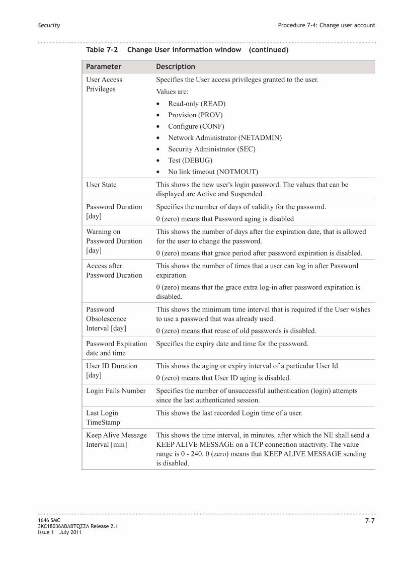
Table 7-2 Change User information window (continued)
Parameter Description
User Access
Privileges
Specifies the User access privileges granted to the user.
Values are:
• Read-only (READ)
• Provision (PROV)
• Configure (CONF)
• Network Administrator (NETADMIN)
• Security Administrator (SEC)
• Test (DEBUG)
• No link timeout (NOTMOUT)
User State This shows the new user's login password. The values that can be
displayed are Active and Suspended
Password Duration
[day]
Specifies the number of days of validity for the password.
0 (zero) means that Password aging is disabled
Warning on
Password Duration
[day]
This shows the number of days after the expiration date, that is allowed
for the user to change the password.
0 (zero) means that grace period after password expiration is disabled.
Access after
Password Duration
This shows the number of times that a user can log in after Password
expiration.
0 (zero) means that the grace extra log-in after password expiration is
disabled.
Password
Obsolescence
Interval [day]
This shows the minimum time interval that is required if the User wishes
to use a password that was already used.
0 (zero) means that reuse of old passwords is disabled.
Password Expiration
date and time
Specifies the expiry date and time for the password.
User ID Duration
[day]
This shows the aging or expiry interval of a particular User Id.
0 (zero) means that User ID aging is disabled.
Login Fails Number Specifies the number of unsuccessful authentication (login) attempts
since the last authenticated session.
Last Login
TimeStamp
This shows the last recorded Login time of a user.
Keep Alive Message
Interval [min]
This shows the time interval, in minutes, after which the NE shall send a
KEEP ALIVE MESSAGE on a TCP connection inactivity. The value
range is 0 - 240. 0 (zero) means that KEEP ALIVE MESSAGE sending
is disabled.
Security Procedure 7-4: Change user account
....................................................................................................................................................................................................................................
....................................................................................................................................................................................................................................
1646 SMC
3KC18036ABABTQZZA Release 2.1
Issue 1 July 2011
7-7

Table 7-2 Change User information window (continued)
Parameter Description
Minimum Interval
between invalid
attempts [sec]
This shows the minimum interval, in seconds, between invalid login
attempts before an NE shall logout a user and lockout the user channel.
The value range is 0 - 60. 0 (zero) means no minimum interval between
consecutive invalid login attempts.
Maximum Invalid
Attempts
This shows the maximum number of invalid login attempts before an NE
shall logout a user and lockout the user channel. The value range is 0 -
15. 0 (zero) means that no limit to the invalid login attempts.
User Session
Inactivity Timeout
[min]
This shows User Session Activity Link TimeOut, specifies the amount of
time (in minutes) that the User Session link is inactive with regards to
user TL1 input before a user session link time-out occurs.
0 (zero) means that no user session link time–out will occur (disabled).
Procedure 7-5: Modify account default settings
When to use
Use this procedure to modify account default settings.
Procedure
...................................................................................................................................................................................................
1 Select Security → Administration → Accounts → Default settings.
The following screen is displayed.
Security Procedure 7-4: Change user account
....................................................................................................................................................................................................................................
....................................................................................................................................................................................................................................
7-8 1646 SMC
3KC18036ABABTQZZA Release 2.1
Issue 1 July 2011
E N D O F S T E P S...................................................................................................................................................................................................

...................................................................................................................................................................................................
2 See Table 7-2, “Change User information window” (p. 7-6) for parameter description.
...................................................................................................................................................................................................
3 Click Default hyperlink next to each parameter to enter the default settings.
...................................................................................................................................................................................................
4 Click Save to save the settings entered on the page.
Procedure 7-6: View current sessions
When to use
Use this procedure to view current sessions.
...................................................................................................................................................................................................
1 Select Security → Administration → Current Sessions.
Figure 7-5 Modify account default settings panel
Security Procedure 7-5: Modify account default settings
....................................................................................................................................................................................................................................
....................................................................................................................................................................................................................................
1646 SMC
3KC18036ABABTQZZA Release 2.1
Issue 1 July 2011
7-9
E N D O F S T E P S...................................................................................................................................................................................................
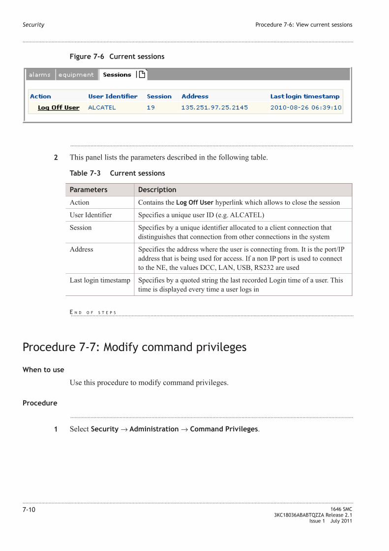
...................................................................................................................................................................................................
2 This panel lists the parameters described in the following table.
Table 7-3 Current sessions
Parameters Description
Action Contains the Log Off User hyperlink which allows to close the session
User Identifier Specifies a unique user ID (e.g. ALCATEL)
Session Specifies by a unique identifier allocated to a client connection that
distinguishes that connection from other connections in the system
Address Specifies the address where the user is connecting from. It is the port/IP
address that is being used for access. If a non IP port is used to connect
to the NE, the values DCC, LAN, USB, RS232 are used
Last login timestamp Specifies by a quoted string the last recorded Login time of a user. This
time is displayed every time a user logs in
Procedure 7-7: Modify command privileges
When to use
Use this procedure to modify command privileges.
Procedure
...................................................................................................................................................................................................
1 Select Security → Administration → Command Privileges.
Figure 7-6 Current sessions
Security Procedure 7-6: View current sessions
....................................................................................................................................................................................................................................
....................................................................................................................................................................................................................................
7-10 1646 SMC
3KC18036ABABTQZZA Release 2.1
Issue 1 July 2011
E N D O F S T E P S...................................................................................................................................................................................................

Figure 7-7 Command Access Privileges page
Security Procedure 7-7: Modify command privileges
....................................................................................................................................................................................................................................
....................................................................................................................................................................................................................................
1646 SMC
3KC18036ABABTQZZA Release 2.1
Issue 1 July 2011
7-11

...................................................................................................................................................................................................
2 The page the command security privileges assigned to the specified TL1 command.
The columns of the table are:
• Action - Contains the hyperlinks in order to modify the security privilege. The
manager actions related to these hyperlinks are:
– The Modify hyperlink activates the following Modify Command Access
Privileges page.
• Command Identifier - Specifies the TL1 command code. The value for the parameter
can be any one of the TL1 command codes, in upper or lower case.
• Command Access Privilege - Allows to choose the User access privileges granted to
the user.
Procedure 7-8: Manage audit
When to use
Use this procedure to activate the Audit Security Log page and retrieve audit log.
Procedure
...................................................................................................................................................................................................
1 Select Security → Administration → Audit.
Figure 7-8 Modify Command Access Privileges panel
Security Procedure 7-7: Modify command privileges
....................................................................................................................................................................................................................................
....................................................................................................................................................................................................................................
7-12 1646 SMC
3KC18036ABABTQZZA Release 2.1
Issue 1 July 2011
E N D O F S T E P S...................................................................................................................................................................................................

...................................................................................................................................................................................................
2 The Audit Log tab contains the Retrieve Audit Log panel with the following parameters:
• From - Specifies the beginning date and time used to filter the response messages. By
means the combo-boxes it is possible to change data and time.
• To - Specifies the beginning date and time used to filter the response messages. By
means the combo-boxes it is possible to change data and time.
• Set User Identifier - The combo-box allows to select the user identifier.
...................................................................................................................................................................................................
3 The Retrieve hyperlink send the command to the agent, then the Retrieve Audit Log
page is reloaded and the table with Security log is displayed
Figure 7-9 Retrieve audit log
Security Procedure 7-8: Manage audit
....................................................................................................................................................................................................................................
....................................................................................................................................................................................................................................
1646 SMC
3KC18036ABABTQZZA Release 2.1
Issue 1 July 2011
7-13

Figure 7-10 Retrieve audit page with results
Security Procedure 7-8: Manage audit
....................................................................................................................................................................................................................................
....................................................................................................................................................................................................................................
7-14 1646 SMC
3KC18036ABABTQZZA Release 2.1
Issue 1 July 2011
E N D O F S T E P S...................................................................................................................................................................................................

Procedure 7-9: Log settings
When to use
Use this procedure to manage the log sessions.
Procedure
...................................................................................................................................................................................................
1 Select Security → Administration → Log Settings.
...................................................................................................................................................................................................
2 The Modify Log Attributes page is made up of description of the TL1 command and the
Modify Log Attributes panel that contains:
• Current Log File Max Size [Mbyte] - Specifies the size, in 1 Megabyte blocks, of the
Security Log File system's disk buffer.
• New Log File Max Size [Mbyte] - Allows to change the size, in 1 Megabyte blocks,
of the Security Log File system's disk buffer. When the SECULOG has reached its
max size, the SECULOG wraps reducing its size to the 70% of its max size discarding
the oldest events (30%). The Default hyperlink allows to set the relevant value
automatically.
Figure 7-11 Modify log attributes
Security Procedure 7-9: Log settings
....................................................................................................................................................................................................................................
....................................................................................................................................................................................................................................
1646 SMC
3KC18036ABABTQZZA Release 2.1
Issue 1 July 2011
7-15

• Current Warning Message - This is the provisioned user-logon warning message is
shown
• New Warning Message - Allows to provision a new user-logon warning message. The
Default hyperlink allows to set the relevant warning message automatically. The Set
Empty hyperlink allows to deplete the entry field.
• Current Log Events - Specifies the current log event.
• Available Log Events - Specifies the list of events that, upon their occurrence, are
included in the security log (i.e., events that are specified for logging, if they occur).
The values are:
– Authentication Event (EIUA) - It logins, logoffs, invalid user authentication
attempts and the alarms/alerts generated due to the invalid authentication attempts
– Changes to the User's Security Accounts (EUSP) - Specifies the details of the
changes made in a user's security profiles and attributes
– Changes to the NE/NS Security Configuration (ESCC) - Specifies the details of
changes made in the NE/NS security configuration
– Changes to NE/NS resources (ECMR) - Specifies the creation and modification of
NE/NS resources performed via standard operations and maintenance procedures.
This does not address creations and modifications carried offline. Commands
creating log events of this type are all the commands not mentioned in the lists
above, having Y in the security field of the command security table
– All Events (ALL) - All events
• New Log Events - This shows the log events for the command. The entry box has the
Default hyperlink in order to set the User access privileges forecast for the account.
They can be copied or removed from one of the entry box using the left or right arrow
buttons available between the two entry boxes.
...................................................................................................................................................................................................
3 Click Save hyperlink to send the command to the agent; the main page is reloaded.
Procedure 7-10: Modify in progress message settings
When to use
Use this procedure to modify in progress message settings.
Procedure
...................................................................................................................................................................................................
1 Select Security → Administration → IP Message Settings.
Security Procedure 7-9: Log settings
....................................................................................................................................................................................................................................
....................................................................................................................................................................................................................................
7-16 1646 SMC
3KC18036ABABTQZZA Release 2.1
Issue 1 July 2011
E N D O F S T E P S...................................................................................................................................................................................................

...................................................................................................................................................................................................
2 The Modify In Progress Message Settings panel is displayed that contains the following
parameters:
• IP Message Interval Time [sec] - Allows to enter IP Message Interval Time in
seconds.
• IP Message Interval Time - Specifies the IP Message Interval Time.
...................................................................................................................................................................................................
3 Click Save to save the settings.
Figure 7-12 Modify in progress message settings panel
Security Procedure 7-10: Modify in progress message settings
....................................................................................................................................................................................................................................
....................................................................................................................................................................................................................................
1646 SMC
3KC18036ABABTQZZA Release 2.1
Issue 1 July 2011
7-17
E N D O F S T E P S...................................................................................................................................................................................................

Security Procedure 7-10: Modify in progress message settings
....................................................................................................................................................................................................................................
....................................................................................................................................................................................................................................
7-18 1646 SMC
3KC18036ABABTQZZA Release 2.1
Issue 1 July 2011

8 8Provisioning: Detailed
level Procedures
Overview
Purpose
Provides an overview of the detailed level procedures documented in this chapter.
Contents
Procedure 8-1: Log into the system 8-2
Procedure 8-2: Log out of the system 8-3
Procedure 8-3: Retrieve software version 8-4
Procedure 8-4: Search VCn cross-connection 8-6
Procedure 8-5: Initialize and Upgrade with a new release 8-9
Procedure 8-6: DB management remote file copy 8-10
Procedure 8-7: DB management cancel remote file copy 8-13
Procedure 8-8: Network Element management 8-14
Procedure 8-9: Change site identifier 8-15
Procedure 8-10: LAC Management 8-16
Procedure 8-11: MAC File Collection 8-18
Procedure 8-12: Administer NTP 8-19
Procedure 8-13: Network IF 8-22
Procedure 8-14: Create XC Overhead 8-24
Procedure 8-15: IP Address 8-26
Procedure 8-16: Configure IP route 8-27
Procedure 8-17: OSI management 8-29
Procedure 8-18: Create linear MSP 8-31
Procedure 8-19: Create MS-SPRing 8-33
Procedure 8-20: LAG management 8-35
Procedure 8-21: Remove LAG member 8-40
...................................................................................................................................................................................................................................
1646 SMC
3KC18036ABABTQZZA Release 2.1
Issue 1 July 2011
8-1

Procedure 8-22: Retrieve system information 8-43
Procedure 8-23: Create IP route 8-45
Procedure 8-24: Create IP tunnel 8-47
Procedure 8-25: NE TL1 Parameter 8-49
Procedure 8-26: Create FTP Server Configuration 8-49
Procedure 8-1: Log into the system
When to use
Use this procedure to log into the Zero Installation Craft (ZIC) terminal.
Procedure
...................................................................................................................................................................................................
1 See Procedure 2-1: “Establish ZIC session” (p. 2-4) for the initial steps to launch the ZIC
session.
...................................................................................................................................................................................................
2 Enter the User Identifier and Password in the respective entry boxes, set the Language
from the drop-down list box. The default is English.
The default User is ALCATEL and password is Alcatel_1.
...................................................................................................................................................................................................
3 Enable the Local Time check box for the network element to display the local time.
...................................................................................................................................................................................................
4 Click Login to log into the system, the browser starts loading the ZIC.
Provisioning: Detailed level Procedures Overview
....................................................................................................................................................................................................................................
....................................................................................................................................................................................................................................
8-2 1646 SMC
3KC18036ABABTQZZA Release 2.1
Issue 1 July 2011

Note: After the maximum number of attempts the user is disabled. Check parameters
for spelling and case-sensitive characters.
Procedure 8-2: Log out of the system
When to use
Use this procedure to log out from the ZIC application.
Procedure
...................................................................................................................................................................................................
1 To log out from the Zero Installation Craft (ZIC) terminal, click the Logout hyperlink
displayed in the top right corner of the ZIC application.
OR
Select Security → Logout.
...................................................................................................................................................................................................
2 The following window appears.
Figure 8-1 ZIC loading
Provisioning: Detailed level Procedures Procedure 8-1: Log into the system
....................................................................................................................................................................................................................................
....................................................................................................................................................................................................................................
1646 SMC
3KC18036ABABTQZZA Release 2.1
Issue 1 July 2011
8-3
E N D O F S T E P S...................................................................................................................................................................................................

...................................................................................................................................................................................................
3 Click Yes to log out of ZIC terminal.
Procedure 8-3: Retrieve software version
When to use
Use this procedure to obtain information about the software version.
Procedure
...................................................................................................................................................................................................
1 From the menu bar, select Help → About option.
...................................................................................................................................................................................................
2 The following window message is displayed.
Figure 8-2 Logout message screen
Provisioning: Detailed level Procedures Procedure 8-2: Log out of the system
....................................................................................................................................................................................................................................
....................................................................................................................................................................................................................................
8-4 1646 SMC
3KC18036ABABTQZZA Release 2.1
Issue 1 July 2011
E N D O F S T E P S...................................................................................................................................................................................................

Figure 8-3 About window
Provisioning: Detailed level Procedures Procedure 8-3: Retrieve software version
....................................................................................................................................................................................................................................
....................................................................................................................................................................................................................................
1646 SMC
3KC18036ABABTQZZA Release 2.1
Issue 1 July 2011
8-5
E N D O F S T E P S...................................................................................................................................................................................................

Procedure 8-4: Search VCn cross-connection
When to use
Use this procedure to retrieve a VCn cross-connection.
Procedure
...................................................................................................................................................................................................
1 Select Connection → TDM Search option from the menu bar to view and set the
cross-connection parameters for the search criteria
The following Connection panel is displayed.
...................................................................................................................................................................................................
2 This panel lists the parameters described in the following table.
Table 8-1 Connection panel
Parameters Description
Retrieve Connection
command
The options are:
• (RTRV-CRS) - To retrieve general cross-connections. This removes
the VC Type drop-down list box.
• (RTRV-CRS-) - To retrieve lower order protected cross-connections..
This option adds the VC Type drop-down list box.
• (RTRV-CRSPROT) - To retrieve protected cross-connections. This
option removes the VC Type
• (RTRV-CRSPROT-) - To retrieve lower order protected
cross-connections.. This option adds the VC Type
Figure 8-4 TDM search
Provisioning: Detailed level Procedures Procedure 8-4: Search VCn cross-connection
....................................................................................................................................................................................................................................
....................................................................................................................................................................................................................................
8-6 1646 SMC
3KC18036ABABTQZZA Release 2.1
Issue 1 July 2011

Table 8-1 Connection panel (continued)
Parameters Description
Filter by Access
Identifier Type
Allows to filter by Access Identifier Type
...................................................................................................................................................................................................
3 Click Search. The system retrieves the cross-connection details based on the search
parameter defined.
Create VCn cross-connection
...................................................................................................................................................................................................
1 Click on the Create hyperlink as shown in Figure 8-4, “TDM search” (p. 8-6) or select
Connection → TDM Create from the menu bar.
The following screen appears.
Figure 8-5 TDM create with ENT-CRS
Provisioning: Detailed level Procedures Procedure 8-4: Search VCn cross-connection
....................................................................................................................................................................................................................................
....................................................................................................................................................................................................................................
1646 SMC
3KC18036ABABTQZZA Release 2.1
Issue 1 July 2011
8-7
E N D O F S T E P S...................................................................................................................................................................................................

...................................................................................................................................................................................................
2 This panel lists the parameters described in the following table.
Table 8-2 Create Connection panel
Parameters Description
Enter Command The options are:
• ENT-CRS
• ENT-CRSPROT
VC type is selected using the drop-down list.
From Allows to select the start direction.
To Allows to select the end point.
Cross Connection
Type
Cross Connection Type is 1WAY for ENT-CRS and 1WAYSNCP for
ENT-CRSPROT
Revertive The options are:
• Y - Yes
• N - No
Revertive Timer Valid range is from 1 to 12 mins.
Hold Off Time Values are 0, 100, 300, 500, 700, 1000, 3000, 5000, 10000
Protection Type The options are:
• SNCN
• SNCI
...................................................................................................................................................................................................
3 Click Select hyperlink to select the From and To directions.
The following window pops up.
Figure 8-6 TDM create with ENT-CRSPROT
Provisioning: Detailed level Procedures Procedure 8-4: Search VCn cross-connection
....................................................................................................................................................................................................................................
....................................................................................................................................................................................................................................
8-8 1646 SMC
3KC18036ABABTQZZA Release 2.1
Issue 1 July 2011
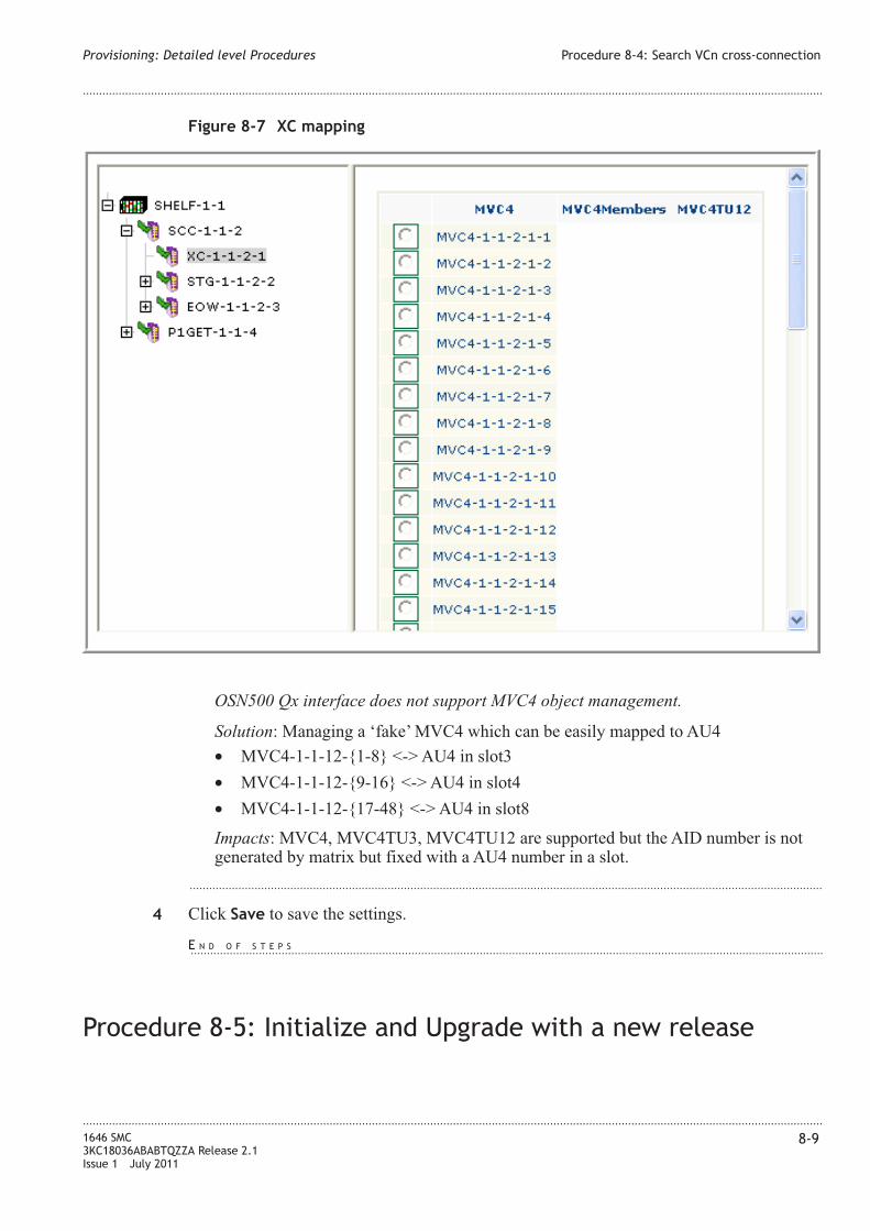
OSN500 Qx interface does not support MVC4 object management.
Solution: Managing a ‘fake’ MVC4 which can be easily mapped to AU4
• MVC4-1-1-12-{1-8} <-> AU4 in slot3
• MVC4-1-1-12-{9-16} <-> AU4 in slot4
• MVC4-1-1-12-{17-48} <-> AU4 in slot8
Impacts: MVC4, MVC4TU3, MVC4TU12 are supported but the AID number is not
generated by matrix but fixed with a AU4 number in a slot.
...................................................................................................................................................................................................
4 Click Save to save the settings.
Procedure 8-5: Initialize and Upgrade with a new release
Figure 8-7 XC mapping
Provisioning: Detailed level Procedures Procedure 8-4: Search VCn cross-connection
....................................................................................................................................................................................................................................
....................................................................................................................................................................................................................................
1646 SMC
3KC18036ABABTQZZA Release 2.1
Issue 1 July 2011
8-9
E N D O F S T E P S...................................................................................................................................................................................................
When to use
This option starts the background activity on the NE to perform the actual switch over
from the current release to the new release. This option returns a completion message to
the user when the background activity is successfully started.
A copy of the primary database is generated during its execution and used for database
conversion in the upgrade processing. This backup is also used to revert to the old release
database when the Initialize System With Old Release option is issued after the system is
upgraded to the new release.
Procedure
...................................................................................................................................................................................................
1 Select System Management → Initialize and Upgrade → Initialize System → With
New Release.
...................................................................................................................................................................................................
2 The panel contains the Apply hyperlink that is used to start the new release downloading
procedure.
Procedure 8-6: DB management remote file copy
When to use
Use this procedure to perform remote file copy.
Procedure
...................................................................................................................................................................................................
1 Select System Management → DB Management → Remote File → Perform Copy.
Provisioning: Detailed level Procedures Procedure 8-5: Initialize and Upgrade with a new release
....................................................................................................................................................................................................................................
....................................................................................................................................................................................................................................
8-10 1646 SMC
3KC18036ABABTQZZA Release 2.1
Issue 1 July 2011
E N D O F S T E P S...................................................................................................................................................................................................

Figure 8-8 Copy remote file panel
Provisioning: Detailed level Procedures Procedure 8-6: DB management remote file copy
....................................................................................................................................................................................................................................
....................................................................................................................................................................................................................................
1646 SMC
3KC18036ABABTQZZA Release 2.1
Issue 1 July 2011
8-11

...................................................................................................................................................................................................
2 This panel lists the parameters described in the following table.
Table 8-3 Copy remote file panel parameters
Parameters Description
From Determines the location from which the DB remote file is to be copied.
The supported values are:
• Database backup on a Remote File Server (RFSDB) - Represents a
database on a Remote File Server. Multiple instances of RFSDB can
exist in different locations on an RFS. A specific instance is always
addressed with this AID, with the addition of information in the
LOCATION parameter in the command.
• Software Generic on a Remote File Server (RFSSW) - Represents a
software generic on a Remote File Server. Multiple instances of
RFSSW can exist in different locations on an RFS. A specific
instance is always addressed with this AID, with the addition of
information in the LOCATION parameter in the command.
• Local NE PM Global File collection (LOCPMGLB) - Represents the
PM Global File Collection in the local NE. There is a maximum of
one instance of LOCPMGLB in the NE.
• LOCMACGLB (LOCMACGLB) - Represents the MAC File
Collection in the local NE. There is a maximum of one instance of
LOCMACGLB in the NE.
• System's primary backup database (ACTDSKDB) - Represents the
active database in the local NE .
To Determines the location to which the DB remote file is to be copied.
The supported values are:
• Database Backup on a Remote File Server (RFSDB)
• Remote File Server PM Global File Collection (RFSPMGLB) -
Represents the PM Global File Collection on a Remote File Server.
Multiple instances of RFSPMGLB can exist in different locations on
an RFS.A specific instance is always addressed with this AID, with
the addition of information in the LOCATION parameter in the
command.
• Remote File Server MAC File Collection (RFSMACGLB) -
Represents the MAC File Collection on a Remote File Server.
Multiple instances of RFSMACGLB can exist in different locations
on an RFS. A specific instance is always addressed with this AID,
with the addition of information in the LOCATION parameter in the
command.
• System's primary backup database (ACTDSKDB)
• Active software generic on the NE (ACTSW)
User The user identifier used for the ftp connection on the RFS.
Password The user password used for the ftp connection on the RFS
Host The IP address of the host (the Remote File Server)
Provisioning: Detailed level Procedures Procedure 8-6: DB management remote file copy
....................................................................................................................................................................................................................................
....................................................................................................................................................................................................................................
8-12 1646 SMC
3KC18036ABABTQZZA Release 2.1
Issue 1 July 2011

Table 8-3 Copy remote file panel parameters (continued)
Parameters Description
Port The port number to connect to. Most schemes designate protocols that
have a default port number.
URL Path The details of how the specified resource (i.e. the directory where the
file(s) reside) can be accessed.
...................................................................................................................................................................................................
3 Click Apply to apply the configuration settings.
Procedure 8-7: DB management cancel remote file copy
When to use
Use this procedure to cancel the copy of remote file.
Procedure
...................................................................................................................................................................................................
1 Select System Management → DB Management → Remote File → Cancel Copy.
Figure 8-9 Cancel Copy of Remote File panel
Provisioning: Detailed level Procedures Procedure 8-6: DB management remote file copy
....................................................................................................................................................................................................................................
....................................................................................................................................................................................................................................
1646 SMC
3KC18036ABABTQZZA Release 2.1
Issue 1 July 2011
8-13
E N D O F S T E P S...................................................................................................................................................................................................

...................................................................................................................................................................................................
2 The Remote file tab displays the Cancel Copy of Remote File panel that contains the
following parameters.
Table 8-4 Cancel Copy of Remote File panel parameters
Parameters Description
From Determines the location from which the DB remote file copy is to be
cancelled.
The supported values are:
• Database backup on a Remote File Server (RFSDB)
• Software Generic on a Remote File Server (RFSSW)
• Local NE PM Global File collection (LOCPMGLB)
• LOCMACGLB (LOCMACGLB)
• System's primary backup database (ACTDSKDB)
To Determines the location to which the DB remote file copy is to be
cancelled.
The supported values are:
• Database Backup on a Remote File Server (RFSDB)
• Remote File Server PM Global File Collection (RFSPMGLB)
• Remote File Server MAC File Collection (RFSMACGLB)
• System's primary backup database (ACTDSKDB)
• Active software generic on the NE (ACTSW)
...................................................................................................................................................................................................
3 Click Apply to apply the configuration settings.
Procedure 8-8: Network Element management
When to use
Use this procedure to retrieve general system level configuration information consisting
of: system type, software release identifier, software release date, matrix size, system
restart status.
Procedure
...................................................................................................................................................................................................
1 Select System Management → DB Management → Network Element.
Provisioning: Detailed level Procedures Procedure 8-7: DB management cancel remote file copy
....................................................................................................................................................................................................................................
....................................................................................................................................................................................................................................
8-14 1646 SMC
3KC18036ABABTQZZA Release 2.1
Issue 1 July 2011
E N D O F S T E P S...................................................................................................................................................................................................

...................................................................................................................................................................................................
2 The System Configuration tab displays the following general system level configuration
information.
• Access Identifier
• Matrix Size
• Node Type
• Provision Mode
• Region
• Release Date
• Release Identification
• System Restart Process Status
• System Type
• USER LABEL
Procedure 8-9: Change site identifier
When to use
Use this procedure to change the unique site identifier (SID) for the NE.
The SID value can be either up to 20 noncase-sensitive alphanumeric characters,
including the special hyphen (-) character, or up to 20 characters quoted string.
If it is a non quoted string, the hyphen (-) is the only special character allowed. The SID
must start with a letter and shall end with an alphanumeric character. Consecutive
hyphens (-) shall not be allowed. Number of hyphens shall be not greater than 4. If a
lower-case character string is entered for the SID, it is automatically converted to an
uppercase character string for comparison to any TID value entered in a command.
If it is a quoted string, any character is allowed, included any special character, and no
case conversion is applied. On initial turn-up, the NE shall automatically generate an
unique SID, using the last 5 hexadecimal characters of the NE's MAC address and
appending them to the PLEASE- SET-SID name. This SID is updated (by reading the
Figure 8-10 System configuration
Provisioning: Detailed level Procedures Procedure 8-8: Network Element management
....................................................................................................................................................................................................................................
....................................................................................................................................................................................................................................
1646 SMC
3KC18036ABABTQZZA Release 2.1
Issue 1 July 2011
8-15
E N D O F S T E P S...................................................................................................................................................................................................
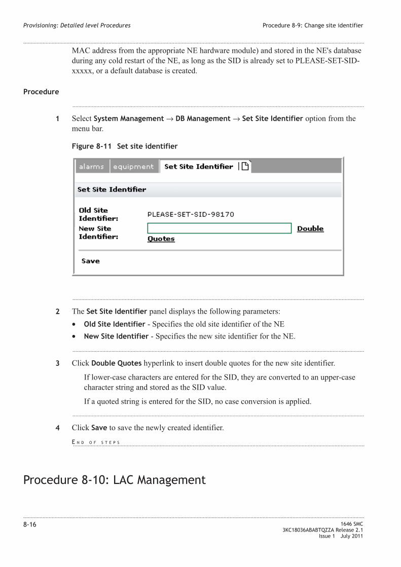
MAC address from the appropriate NE hardware module) and stored in the NE's database
during any cold restart of the NE, as long as the SID is already set to PLEASE-SET-SID-
xxxxx, or a default database is created.
Procedure
...................................................................................................................................................................................................
1 Select System Management → DB Management → Set Site Identifier option from the
menu bar.
...................................................................................................................................................................................................
2 The Set Site Identifier panel displays the following parameters:
• Old Site Identifier - Specifies the old site identifier of the NE
• New Site Identifier - Specifies the new site identifier for the NE.
...................................................................................................................................................................................................
3 Click Double Quotes hyperlink to insert double quotes for the new site identifier.
If lower-case characters are entered for the SID, they are converted to an upper-case
character string and stored as the SID value.
If a quoted string is entered for the SID, no case conversion is applied.
...................................................................................................................................................................................................
4 Click Save to save the newly created identifier.
Procedure 8-10: LAC Management
Figure 8-11 Set site identifier
Provisioning: Detailed level Procedures Procedure 8-9: Change site identifier
....................................................................................................................................................................................................................................
....................................................................................................................................................................................................................................
8-16 1646 SMC
3KC18036ABABTQZZA Release 2.1
Issue 1 July 2011
E N D O F S T E P S...................................................................................................................................................................................................

When to use
Local Access Control (LAC) is used to manage the ZIC.
This option displays the current and default status of the DB management.
LAC state management
...................................................................................................................................................................................................
1 Select System Management → DB Management → Lac → State.
...................................................................................................................................................................................................
2 The LAC state tab displays the Lac State Management panel that contains the following
parameters.
Table 8-5 Lac state panel parameters
Parameters Description
LAC current state Specifies the current LAC state. The default value is Granted.
LAC state Specifies the LAC state. The values are Requested or Denied.
• Requested - Indicates that the local CRAFT is waiting to get access
the NE to send provisioning data.
• Denied - Indicates that the local CRAFT is denied to access the NE
to send provisioning data.
...................................................................................................................................................................................................
3 Click Save hyperlink to save the settings.
Figure 8-12 LAC State Management panel
Provisioning: Detailed level Procedures Procedure 8-10: LAC Management
....................................................................................................................................................................................................................................
....................................................................................................................................................................................................................................
1646 SMC
3KC18036ABABTQZZA Release 2.1
Issue 1 July 2011
8-17
E N D O F S T E P S...................................................................................................................................................................................................

LAC default management
...................................................................................................................................................................................................
1 Select System Management → DB Management → Lac → Default.
...................................................................................................................................................................................................
2 Click Save hyperlink to save the settings.
Procedure 8-11: MAC File Collection
When to use
The mechanism of MAC File Collection is an efficient way of collecting MAC adrresses
of the entire NE in a single file.
The collection of MAC data will be done on the basis of the input filtering, where the
input filters consists of MAC address, slot AIDs and FDB IDs. The MAC File Collection
then generated will contain one line (record) for every retrieved MAC address in the NE
according to the input filtering.
Procedure
...................................................................................................................................................................................................
1 Select System Management → MAC File Collection.
Figure 8-13 MAC File Collection
Provisioning: Detailed level Procedures Procedure 8-10: LAC Management
....................................................................................................................................................................................................................................
....................................................................................................................................................................................................................................
8-18 1646 SMC
3KC18036ABABTQZZA Release 2.1
Issue 1 July 2011
E N D O F S T E P S...................................................................................................................................................................................................

...................................................................................................................................................................................................
2 The MAC File Collection tab displays the following panels.
• MAC File Collection Status
• MAC File Collection
...................................................................................................................................................................................................
3 The MAC File Collection Status panel displays the Collection State and contains the
following hyperlinks:
• Refresh
• File View
...................................................................................................................................................................................................
4 The MAC File Collection panel displays the following parameters.
Table 8-6 MAC File Collection panel parameters
Parameters Description
MAC Address Allows to enter the MAC Address
Board Allows to select the board
VLAN Specifies the input filtering VLAN for the collection preparation.
MAC Learning Type Specifies the type of MAC learning. Dynamically Learned MAC and
Static MAC
...................................................................................................................................................................................................
5 Click Set Empty to make the entries empty.
Procedure 8-12: Administer NTP
When to use
This procedure provides the instructions to retrieve the Network Time Protocol (NTP)
server IP address, provision NTP servers, and delete NTP servers. It also provides
instructions to enable and disable the NTP synchronization.
NTP servers are used for time-of-day synchronization when the NTP protocol is enabled.
If no NTP server is entered and the NTP protocol is enabled, the time-of-day clock
synchronizes with the last known internal clock frequency.
When NTP is enabled, the NE internal time-of-day clock uses the calculated Coordinated
Universal Time (UTC) from the selected NTP server, which is modified by the
user-provisioned offset. All messages, event reports, logs, and events that carry time
stamps use the following time of day: NTP UTC time + provisioned offset.
Provisioning: Detailed level Procedures Procedure 8-11: MAC File Collection
....................................................................................................................................................................................................................................
....................................................................................................................................................................................................................................
1646 SMC
3KC18036ABABTQZZA Release 2.1
Issue 1 July 2011
8-19
E N D O F S T E P S...................................................................................................................................................................................................

Procedure
...................................................................................................................................................................................................
1 Select System Management → Network Time Protocol option from the menu bar.
The NTP config tab contains the Time and Date and Network Time Protocol panels.
...................................................................................................................................................................................................
2 The Time and Date panel allows to manually set the system date and time by means of
six combo-boxes Year, Month, Day, Hour, Minute and Sec. This command is not allowed
if NTP is enabled as shown in Figure 8-15, “NTP Config - with Enabled Server
Synchronization” (p. 8-21).
...................................................................................................................................................................................................
3 Click Save to save the settings and Refresh to refresh the page.
Figure 8-14 NTP Config - with Disabled Server Synchronization
Provisioning: Detailed level Procedures Procedure 8-12: Administer NTP
....................................................................................................................................................................................................................................
....................................................................................................................................................................................................................................
8-20 1646 SMC
3KC18036ABABTQZZA Release 2.1
Issue 1 July 2011

...................................................................................................................................................................................................
4 The Network Time Protocol panel shows the following information.
• Current NTP Server Synchronization - The time synchronization from the NTP
server; The value are Enabled or Disabled. Factory default is Disabled
• Current Offset - The time offset to apply to NTP server UTC time, +/- HH-MM, for
all events and time stamps reported by this NE. Factory default is +08-00
• Current Operating Mode - The current operating mode of the NTP service. The
values are: NTPSYNC - NTP is enabled, and the NE is using the NTP protocol to
synchronize to an NTP server.
• NTP Server Synchronization
• New Offset
...................................................................................................................................................................................................
5 Click Create hyperlink and the following window appears.
Figure 8-15 NTP Config - with Enabled Server Synchronization
Provisioning: Detailed level Procedures Procedure 8-12: Administer NTP
....................................................................................................................................................................................................................................
....................................................................................................................................................................................................................................
1646 SMC
3KC18036ABABTQZZA Release 2.1
Issue 1 July 2011
8-21

The NTP Server Address Provision window contains:
–Server IP Address - Four entry boxes whose allow to digit the IP address of an NTP
server. the address in the [0-126,128-223]-[0-255]-[0-255]-[0-255] format.
The window has the following hyperlinks:
• Cancel allows to leave the page without applying the previously selections.
• Save allows to apply the previously selections.
...................................................................................................................................................................................................
6 Click Delete hyperlink to delete the selected IP address.
Procedure 8-13: Network IF
When to use
Use this procedure to modify the various network interface parameters on a specified
DCC channel on an optical port for data communication purposes. The network interface
must be first provisioned on the line or section DCC of the specific STMn facility. The
DCC is identified as STMn and the DCCCHNL parameter.
Procedure
...................................................................................................................................................................................................
1 Select Communication → DCC → Network IF option from the menu bar.
Figure 8-16 NTP Server Address Provision
Provisioning: Detailed level Procedures Procedure 8-12: Administer NTP
....................................................................................................................................................................................................................................
....................................................................................................................................................................................................................................
8-22 1646 SMC
3KC18036ABABTQZZA Release 2.1
Issue 1 July 2011
E N D O F S T E P S...................................................................................................................................................................................................
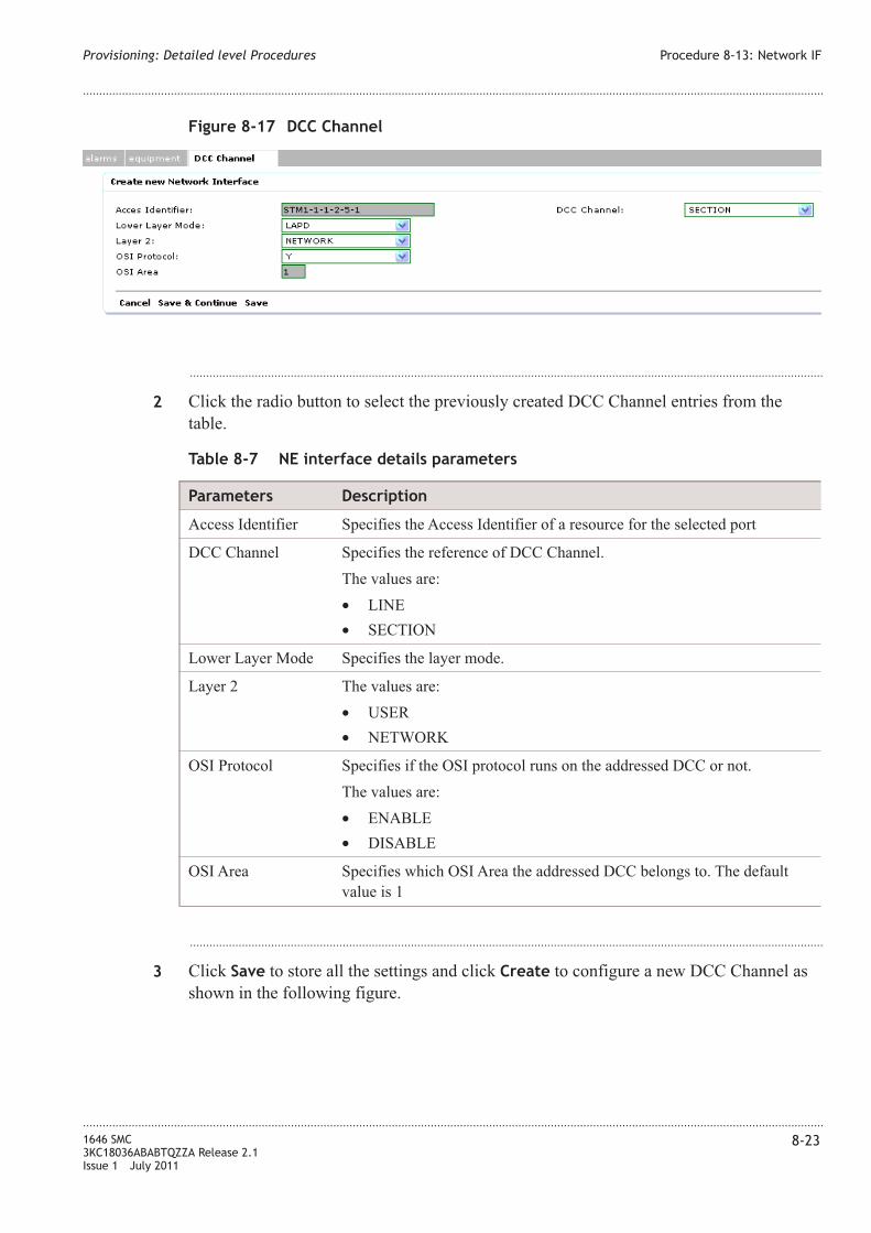
...................................................................................................................................................................................................
2 Click the radio button to select the previously created DCC Channel entries from the
table.
Table 8-7 NE interface details parameters
Parameters Description
Access Identifier Specifies the Access Identifier of a resource for the selected port
DCC Channel Specifies the reference of DCC Channel.
The values are:
• LINE
• SECTION
Lower Layer Mode Specifies the layer mode.
Layer 2 The values are:
• USER
• NETWORK
OSI Protocol Specifies if the OSI protocol runs on the addressed DCC or not.
The values are:
• ENABLE
• DISABLE
OSI Area Specifies which OSI Area the addressed DCC belongs to. The default
value is 1
...................................................................................................................................................................................................
3 Click Save to store all the settings and click Create to configure a new DCC Channel as
shown in the following figure.
Figure 8-17 DCC Channel
Provisioning: Detailed level Procedures Procedure 8-13: Network IF
....................................................................................................................................................................................................................................
....................................................................................................................................................................................................................................
1646 SMC
3KC18036ABABTQZZA Release 2.1
Issue 1 July 2011
8-23

...................................................................................................................................................................................................
4 Select the AID type from the combo-box to filter DCC Channel that the user wants to
configure.
...................................................................................................................................................................................................
5 Click Search to filter the DCC Channel.
...................................................................................................................................................................................................
6 The available resources are displayed, else No configurable resources found message is
displayed.
...................................................................................................................................................................................................
7 Click Cancel to revoke all the settings and return to the previous page.
Procedure 8-14: Create XC Overhead
When to use
Use this procedure to create overhead channel cross-connection.
Procedure
...................................................................................................................................................................................................
1 Select Communication → DCC → XC Overhead from the menu bar.
Figure 8-18 DCC channel - filter by
Provisioning: Detailed level Procedures Procedure 8-13: Network IF
....................................................................................................................................................................................................................................
....................................................................................................................................................................................................................................
8-24 1646 SMC
3KC18036ABABTQZZA Release 2.1
Issue 1 July 2011
E N D O F S T E P S...................................................................................................................................................................................................
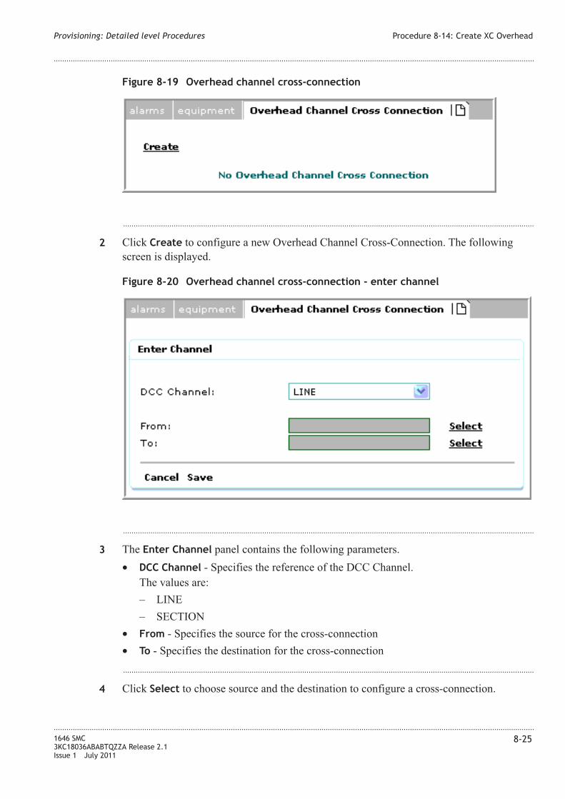
...................................................................................................................................................................................................
2 Click Create to configure a new Overhead Channel Cross-Connection. The following
screen is displayed.
...................................................................................................................................................................................................
3 The Enter Channel panel contains the following parameters.
• DCC Channel - Specifies the reference of the DCC Channel.
The values are:
– LINE
– SECTION
• From - Specifies the source for the cross-connection
• To - Specifies the destination for the cross-connection
...................................................................................................................................................................................................
4 Click Select to choose source and the destination to configure a cross-connection.
Figure 8-19 Overhead channel cross-connection
Figure 8-20 Overhead channel cross-connection - enter channel
Provisioning: Detailed level Procedures Procedure 8-14: Create XC Overhead
....................................................................................................................................................................................................................................
....................................................................................................................................................................................................................................
1646 SMC
3KC18036ABABTQZZA Release 2.1
Issue 1 July 2011
8-25
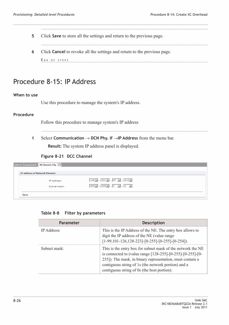
...................................................................................................................................................................................................
5 Click Save to store all the settings and return to the previous page.
...................................................................................................................................................................................................
6 Click Cancel to revoke all the settings and return to the previous page.
Procedure 8-15: IP Address
When to use
Use this procedure to manage the system's IP address.
Procedure
Follow this procedure to manage system's IP address
...................................................................................................................................................................................................
1 Select Communication → DCN Phy. If →IP Address from the menu bar.
Result: The system IP address panel is displayed.
Table 8-8 Filter by parameters
Parameter Description
IP Address: This is the IP Address of the NE. The entry box allows to
digit the IP address of the NE (value range
[1-99,101-126,128-223]-[0-255]-[0-255]-[0-254]).
Subnet mask: This is the entry box for subnet mask of the network the NE
is connected to (value range [128-255]-[0-255]-[0-255]-[0-
255]). The mask, in binary representation, must contain a
contiguous string of 1s (the network portion) and a
contiguous string of 0s (the host portion).
Figure 8-21 DCC Channel
Provisioning: Detailed level Procedures Procedure 8-14: Create XC Overhead
....................................................................................................................................................................................................................................
....................................................................................................................................................................................................................................
8-26 1646 SMC
3KC18036ABABTQZZA Release 2.1
Issue 1 July 2011
E N D O F S T E P S...................................................................................................................................................................................................

...................................................................................................................................................................................................
2 Click Save link to store the settings and return back to the previous page.
Procedure 8-16: Configure IP route
When to use
Use this procedure to configure the IP Routing and enter (add) a new static IP route in the
IP routing table.
Procedure
Follow this procedure to configure the IP Routing:
...................................................................................................................................................................................................
1 Click Communication→Network Domain→IP Route from the menu bar.
Result: The IP Routing Configuration panel is displayed.
The panel displays the existing IP route entry along with its attributes.
...................................................................................................................................................................................................
2 Click Create hyperlink to configure a new IP route as displayed in Figure 8-22, “IP route
creation” (p. 8-27).
Figure 8-22 IP route creation
Provisioning: Detailed level Procedures Procedure 8-15: IP Address
....................................................................................................................................................................................................................................
....................................................................................................................................................................................................................................
1646 SMC
3KC18036ABABTQZZA Release 2.1
Issue 1 July 2011
8-27
E N D O F S T E P S...................................................................................................................................................................................................

Table 8-9, “IP Routing panel parameters” (p. 8-28) provides description of the IP route
panel parameters.
Table 8-9 IP Routing panel parameters
Parameter Description
Access Identifier Access Identifier, it specifies the facility carrying the DCC with the next
hop network interface or identifies the IP Tunnel or Customer LAN. The
select hyperlink allows to open the window shown in Figure 8-23, “AID
Type Selection” (p. 8-28) for the selection of the resource. After the
selection procedure, the chosen value will be reported
Destination Address This is the IP address of the destination host or network (in the format
nnn-nnn-nnn-nnn). The address 0-0-0-0 is used to specify a default
route. If NETMASK is not all '1' (that is, a network route is specified),
the host portion of the DESTADDR must be all '0'
Subnet Mask This is the IP subnet mask of the route (in the format nnn-nnnnnn- nnn).
The mask 0-0-0-0 is used to specify a default route
Metric This is the cost metric of the route. The valid range is 1- 65535
Status Specifies the status of the configuration.
...................................................................................................................................................................................................
3 Enter the Access Identifier for the new IP route. Click Select hyperlink to choose the AID
type. The values are DCC, NE IPT, and LAN as shown in Figure 8-23, “AID Type
Selection” (p. 8-28).
...................................................................................................................................................................................................
4 Select one of the radio button to choose the AID value and click Send hyperlink, the
choice are added in the relevant field of the previous page. Close hyperlink allows to
leave the window.
...................................................................................................................................................................................................
5 Enter the Destination Address and Subnet mask for the IP route to be configured.
Figure 8-23 AID Type Selection
Provisioning: Detailed level Procedures Procedure 8-16: Configure IP route
....................................................................................................................................................................................................................................
....................................................................................................................................................................................................................................
8-28 1646 SMC
3KC18036ABABTQZZA Release 2.1
Issue 1 July 2011

...................................................................................................................................................................................................
6 Enter the Metric value and set the Advertise value to either Y or N.
...................................................................................................................................................................................................
7 Click Save & Exit to save the settings and return to the window.
...................................................................................................................................................................................................
8 Click Save to store the settings and return to the previous panel.
...................................................................................................................................................................................................
9 Click Cancel to revoke all the settings and return to the previous page.
Procedure 8-17: OSI management
When to use
This option retrieves the parameters of a configured OSI AREA that the NE is part of.
It contains the following two sub-menu options:
• OSI NE Area
• OSI OS Address
Administer OSI NE area
...................................................................................................................................................................................................
1 Select Communication → Network Domain → OSI Mng → OSI NE Area option from the
menu bar. The OSI area panel is displayed as shown in Figure 8-24, “OSI Area” (p. 8-29).
Figure 8-24 OSI Area
Provisioning: Detailed level Procedures Procedure 8-16: Configure IP route
....................................................................................................................................................................................................................................
....................................................................................................................................................................................................................................
1646 SMC
3KC18036ABABTQZZA Release 2.1
Issue 1 July 2011
8-29
E N D O F S T E P S...................................................................................................................................................................................................

...................................................................................................................................................................................................
2 Table 8-10, “OSI area panel parameters” (p. 8-30) provides description of OSI NE area
parameters.
Table 8-10 OSI area panel parameters
Parameter Description
OSI AREA Determines an access Identifier for an OSI area
Level 3 Initial
Domain Part
Assigns the initial domain part of the manual area address (8
hexadecimal characters)
Level 3 Domain
Format Identifier
Assigns the domain format identifier field of the manual area address (2
hexadecimal characters)
Level 3
ORGanization
Assigns the organization field of the manual area address (8 hexadecimal
characters)
Level 3 Reserved Assigns the reserved field of the manual area address (4 hexadecimal
characters)
Level 3 Routing Assigns the routing domain and routing area within the routing domain
of the manual area address (8 hexadecimal characters)
Level 3 System
Identifier
This is the system identifier assigned to the card (12 hexadecimal
characters)
...................................................................................................................................................................................................
3 The Save hyperlink closes the page and return back to the previous page.
Administer OSI OS address
...................................................................................................................................................................................................
1 Select Communication → Network Domain → OSI Mng → OSI OS Address option from
the menu bar. The OS Address panel is displayed as shown in Figure 8-25, “OS Address”
(p. 8-30).
Figure 8-25 OS Address
Provisioning: Detailed level Procedures Procedure 8-17: OSI management
....................................................................................................................................................................................................................................
....................................................................................................................................................................................................................................
8-30 1646 SMC
3KC18036ABABTQZZA Release 2.1
Issue 1 July 2011
E N D O F S T E P S...................................................................................................................................................................................................
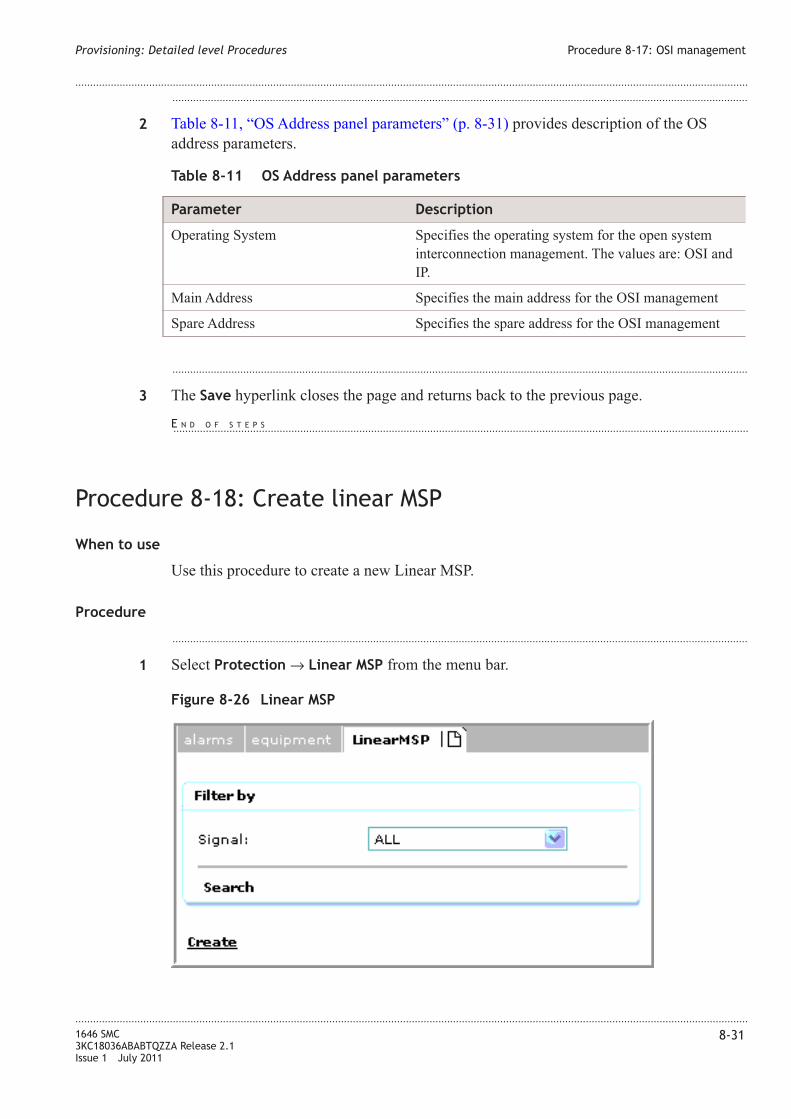
...................................................................................................................................................................................................
2 Table 8-11, “OS Address panel parameters” (p. 8-31) provides description of the OS
address parameters.
Table 8-11 OS Address panel parameters
Parameter Description
Operating System Specifies the operating system for the open system
interconnection management. The values are: OSI and
IP.
Main Address Specifies the main address for the OSI management
Spare Address Specifies the spare address for the OSI management
...................................................................................................................................................................................................
3 The Save hyperlink closes the page and returns back to the previous page.
Procedure 8-18: Create linear MSP
When to use
Use this procedure to create a new Linear MSP.
Procedure
...................................................................................................................................................................................................
1 Select Protection → Linear MSP from the menu bar.
Figure 8-26 Linear MSP
Provisioning: Detailed level Procedures Procedure 8-17: OSI management
....................................................................................................................................................................................................................................
....................................................................................................................................................................................................................................
1646 SMC
3KC18036ABABTQZZA Release 2.1
Issue 1 July 2011
8-31
E N D O F S T E P S...................................................................................................................................................................................................

...................................................................................................................................................................................................
2 Select the available STMn Signal from the combo-box for which the user wants to
configure a Linear MSP.
...................................................................................................................................................................................................
3 Click Create to configure a new Linear MSP.
...................................................................................................................................................................................................
4 Linear Multiplex Section Protection Provision panel parameters are described in the
following table.
Table 8-12 NE interface details parameters
Parameters Description
FFP Access
Identifier
Specifies the Access Identifier for Fast Facility Protection
Protection Type Specifies the type of protection. The default values is Linear
Revertive Mode The values are Y or N
Revertive Delay
Time (min)
The valid range is from 0-15
Hold Off Time
(msec)
Indicates the Hold off time in milliseconds. The valid range is 0–10000.
Protected Access
Identifier
Specifies the Access Identifier for the protected resource
Protecting Access
Identifier
Specifies the Access Identifier for the protecting resource
Protection Switching
Direction
Specifies the switching direction. The values are UNI or BI
Figure 8-27 Linear multiplex section protection provision panel
Provisioning: Detailed level Procedures Procedure 8-18: Create linear MSP
....................................................................................................................................................................................................................................
....................................................................................................................................................................................................................................
8-32 1646 SMC
3KC18036ABABTQZZA Release 2.1
Issue 1 July 2011

...................................................................................................................................................................................................
5 Click Select to choose the Protected Access Identifier and Protecting Access
Identifier.
...................................................................................................................................................................................................
6 Click Save to store all the settings and return to the previous page.
...................................................................................................................................................................................................
7 Click Cancel to revoke all the settings and return to the previous page.
Procedure 8-19: Create MS-SPRing
When to use
Use this procedure to create a new MS-SPRing.
Procedure
...................................................................................................................................................................................................
1 Select Protection → MS-SPRing from the menu bar.
Result: The MS-SPRing panel is displayed.
...................................................................................................................................................................................................
2 Select the available STMn Signal from the drop-down list for which the user wants to
configure a MS-SP.
...................................................................................................................................................................................................
3 Click Search to view the provisioned MS-SPRing.
Result: The available list of provisioned MS-SPRings is displayed.
...................................................................................................................................................................................................
4 Click Create to configure a new MS-SPRing.
Provisioning: Detailed level Procedures Procedure 8-18: Create linear MSP
....................................................................................................................................................................................................................................
....................................................................................................................................................................................................................................
1646 SMC
3KC18036ABABTQZZA Release 2.1
Issue 1 July 2011
8-33
E N D O F S T E P S...................................................................................................................................................................................................

...................................................................................................................................................................................................
5 Multiplex Section Shared Protection RingProvision panel parameters are described in
the following table.
Table 8-13 NE interface details parameters
Parameters Description
FFP Access
Identifier
Specifies the Access Identifier for Fast Facility Protection
Protection Type Specifies the type of protection. The default values is MSSPRING2F
Revertive Mode The values are Y or N
Revertive Delay
Time (min)
The valid range is from 0-15
Hold Off Time
(msec)
Indicates the Hold off time in milliseconds. The valid range is 0–10000.
East Access
Identifier
Specifies the east side for the MS-SPRing is created.
Important:
The East and West Access identifiers should have the same data rates.
West Access
Identifier
Specifies the west side for the MS-SPRing is created.
Important:
The East and West Access identifiers should have the same data rates.
Node Identifier Indicates the node identifier connected to MS-SPRing. The valid range
is 0–15.
Node Descriptor Indicates the MS-SPRing node descriptor. The valid range is 0–255
ASCII characters.
...................................................................................................................................................................................................
6 Click Save to store all the settings and return to the previous page.
Figure 8-28 Multiplex section shared protection provision panel
Provisioning: Detailed level Procedures Procedure 8-19: Create MS-SPRing
....................................................................................................................................................................................................................................
....................................................................................................................................................................................................................................
8-34 1646 SMC
3KC18036ABABTQZZA Release 2.1
Issue 1 July 2011

...................................................................................................................................................................................................
7 Click Cancel to revoke all the settings and return to the previous page.
Procedure 8-20: LAG management
When to use
The Link Aggregation function is an extension of the MAC layer which allows grouping
of a set of physical Ethernet interfaces into one logical interface with greater capacity and
reliability. The Link Aggregation Group (LAG) is valid only as a link between two
systems (called the Partners). Grouping of more interfaces linking one system with two or
more Partners is not allowed.
Permitted port rates to be aggregated are 1 Gbps and 10 Gbps (10 Mbps and 100 Mbps
are for future release). The max number of ports (LAG-size) to be aggregated is 16; (LAG
stands for Link Aggregation Group). Links may be anytime added or removed to/from the
bundle. Ports to be aggregated can be either located on the same board and also on
different boards.
Its management in the network is based upon the communication, between the aggregate
partner pieces of equipment, of LACP messages (Link Aggregation Control Protocol).
The LACP packets transport information about set-up, aggregation capability, links
failures, automatic reconfiguration after failure, etc.
The benefits of Link Aggregation feature are:
• Bandwidth limitation overcoming
• Load balancing (the traffic is distributed over the constituting links)
• Reliability increasing (in case that a link of the aggregate fails, its traffic is
automatically distributed over the other links of the aggregate).
The conditions for Link Aggregation option are the following:
• All involved ports must work at the same rate.
• All involved ports must have the same configurations, regarding AutoNegotiation and
Flow Control.
• All aggregated links must be point-to-point (multicast is not allowed).
• All involved interfaces must work in full-duplex modality.
• All involved ports must be Local (remote ports are not allowed).
• Actor and Partner ports (local and far sides) must be of the same type.
Create LAG
Use this procedure to create LAG.
Provisioning: Detailed level Procedures Procedure 8-19: Create MS-SPRing
....................................................................................................................................................................................................................................
....................................................................................................................................................................................................................................
1646 SMC
3KC18036ABABTQZZA Release 2.1
Issue 1 July 2011
8-35
E N D O F S T E P S...................................................................................................................................................................................................

...................................................................................................................................................................................................
1 Click LAG Group from the Tree area. The Link Aggregation Mng window is displayed.
...................................................................................................................................................................................................
2 The Link Aggregator Creation panel parameters are described in the following table.
Table 8-14 Link aggregation parameters
Parameter Description
Name Allows to set the name of the LAG; the only suffix after # can be set by
the user, with an integer in the 1 to 123 range
Admin State This item can be set only after creation, in Configure Aggregator option.
The values are:
• enable: the LAG is in-service
• disable: the LAG is out-of-service
User Label Allows to indicate the LAG by means of a name defined by the user.
Size Allows to set the size of the LAG, i.e. number of Aggregated Ports;
possible values are integers in the 1 to 16 range.
Actor Admin Key Allows to indicate the LAG Key, the parameter identifying this LAG;
integer in the 1 to 65535 range.
Figure 8-29 Link aggregation management
Provisioning: Detailed level Procedures Procedure 8-20: LAG management
....................................................................................................................................................................................................................................
....................................................................................................................................................................................................................................
8-36 1646 SMC
3KC18036ABABTQZZA Release 2.1
Issue 1 July 2011

Table 8-14 Link aggregation parameters (continued)
Parameter Description
EthClient Type Indicates the LAG client layer.
The values are:
• ets: for Ethernet Transparent System
• etb: for Ethernet Bridge System
Actor System
Priority
Allows to indicate the LAG Priority. This parameter, together with the
LAG Mac-Address, forms the System Identifier. The lowest System
Identifier value is elected as the Master of the link, i.e. the one that will
drive the actions in case of events such as failures, switches, etc. The
valid range is 0 to 65535.
Type Default value is ieee802.3adLag.
Maximum MRU Specifies the maximum MRU value.
LACP Enabled Link Aggregation Control Protocol (LACP).
...................................................................................................................................................................................................
3 Click Save hyperlink that applies the user’s operation in this page.
...................................................................................................................................................................................................
4 Select the LAG# from the LAG table to select any previously created LAG and Select
Configuration to configure the existing LAG.
Configure LAG
...................................................................................................................................................................................................
1 Click on LAG# from the tree area or select the LAG and select the Configuration
hyperlink.
Provisioning: Detailed level Procedures Procedure 8-20: LAG management
....................................................................................................................................................................................................................................
....................................................................................................................................................................................................................................
1646 SMC
3KC18036ABABTQZZA Release 2.1
Issue 1 July 2011
8-37
E N D O F S T E P S...................................................................................................................................................................................................

Figure 8-30 Link aggregator configuration
Provisioning: Detailed level Procedures Procedure 8-20: LAG management
....................................................................................................................................................................................................................................
....................................................................................................................................................................................................................................
8-38 1646 SMC
3KC18036ABABTQZZA Release 2.1
Issue 1 July 2011

...................................................................................................................................................................................................
2 See Table 8-14, “Link aggregation parameters” (p. 8-36) for Link Aggregator
Configuration panel parameters description.
...................................................................................................................................................................................................
3 Client Type Management panel contains the EthClient Type parameter that indicates the
LAG client layer.
The default value is ets (Ethernet Transparent System).
...................................................................................................................................................................................................
4 The Link Aggregator Configuration panel parameters are described in the following
table.
Table 8-15 Link Aggregator configuration panel parameters
Parameter Description
Mac Address A 6-octet MAC address value (NE MAC Address) consisting of the
unique identifier for Partner System.
Partner System Id A 6-octet System Id value consisting of the unique identifier for Partner
System.
Partner Admin Key Indicates the current administrative value of the Key for Link
Aggregation Group (in Partner System).
Partner Operator
Key
Indicates the current operational value of the Key for LAG (in Partner
System); in case of Active LAG, Partner Admin key = Partner Oper key.
Partner System
Priority
A 2-octet value (NE System Priority) indicating priority value inside
Partner’s NE SystemId.
N. Selected Ports Indicates the number of ports currently selected for aggregation inside
Link Aggregation Group.
N. Attached Ports Indicates the number of ports currently attached to the same Link
Aggregation Group.
Primary Port It is the index of the primary port in Link Aggregation Group used to
send BPDUs and flooding frames; Zero indicates no primary port is
available
Primary Port
Position
It is the port index number in the Link Aggregation Group used to send
BPDUs and flooding frames
...................................................................................................................................................................................................
5 Click Save & Continue to save the settings and configure another LAG.
...................................................................................................................................................................................................
6 Click Save & Exit to save the settings and exit from the window.
Provisioning: Detailed level Procedures Procedure 8-20: LAG management
....................................................................................................................................................................................................................................
....................................................................................................................................................................................................................................
1646 SMC
3KC18036ABABTQZZA Release 2.1
Issue 1 July 2011
8-39

...................................................................................................................................................................................................
7 Click Cancel to cancel all the settings and return to the previous window.
Procedure 8-21: Remove LAG member
When to use
Use this procedure to remove LAG member.
Procedure
...................................................................................................................................................................................................
1 Select the board from the tree area.
...................................................................................................................................................................................................
2 Select one VCG and click Configure LAG.
Figure 8-31 Two member in one LAG
Provisioning: Detailed level Procedures Procedure 8-20: LAG management
....................................................................................................................................................................................................................................
....................................................................................................................................................................................................................................
8-40 1646 SMC
3KC18036ABABTQZZA Release 2.1
Issue 1 July 2011
E N D O F S T E P S...................................................................................................................................................................................................

...................................................................................................................................................................................................
3 The following screen appears.
Figure 8-32 Configure LAG selection
Provisioning: Detailed level Procedures Procedure 8-21: Remove LAG member
....................................................................................................................................................................................................................................
....................................................................................................................................................................................................................................
1646 SMC
3KC18036ABABTQZZA Release 2.1
Issue 1 July 2011
8-41

...................................................................................................................................................................................................
4 Click Select hyperlink to select the Actor Admin key and the following window pops up.
...................................................................................................................................................................................................
5 Click 0 Unlink Port. The following screen appears.
Figure 8-33 Configure LAG
Figure 8-34 Actor Admin key selection window
Provisioning: Detailed level Procedures Procedure 8-21: Remove LAG member
....................................................................................................................................................................................................................................
....................................................................................................................................................................................................................................
8-42 1646 SMC
3KC18036ABABTQZZA Release 2.1
Issue 1 July 2011

...................................................................................................................................................................................................
6 Click Save & exit to save all the changes and exit from the window.
Note: If the member is not the first one, the saved settings are fine. If the member
which is removed is the first one, the following window pops up.
The user needs to change the remove sequence.
Procedure 8-22: Retrieve system information
Figure 8-35 Configure LAG for 0 Unlink Port
Figure 8-36 LAG pop up window
Provisioning: Detailed level Procedures Procedure 8-21: Remove LAG member
....................................................................................................................................................................................................................................
....................................................................................................................................................................................................................................
1646 SMC
3KC18036ABABTQZZA Release 2.1
Issue 1 July 2011
8-43
E N D O F S T E P S...................................................................................................................................................................................................
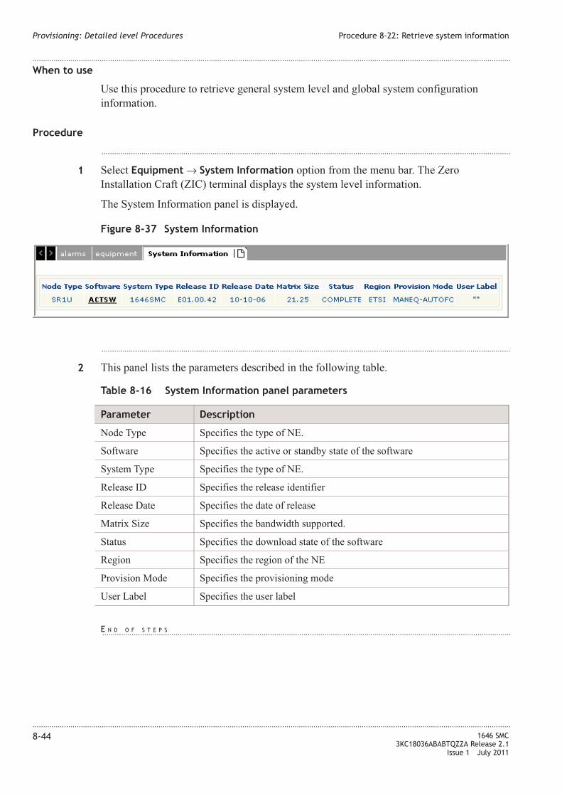
When to use
Use this procedure to retrieve general system level and global system configuration
information.
Procedure
...................................................................................................................................................................................................
1 Select Equipment → System Information option from the menu bar. The Zero
Installation Craft (ZIC) terminal displays the system level information.
The System Information panel is displayed.
...................................................................................................................................................................................................
2 This panel lists the parameters described in the following table.
Table 8-16 System Information panel parameters
Parameter Description
Node Type Specifies the type of NE.
Software Specifies the active or standby state of the software
System Type Specifies the type of NE.
Release ID Specifies the release identifier
Release Date Specifies the date of release
Matrix Size Specifies the bandwidth supported.
Status Specifies the download state of the software
Region Specifies the region of the NE
Provision Mode Specifies the provisioning mode
User Label Specifies the user label
Figure 8-37 System Information
Provisioning: Detailed level Procedures Procedure 8-22: Retrieve system information
....................................................................................................................................................................................................................................
....................................................................................................................................................................................................................................
8-44 1646 SMC
3KC18036ABABTQZZA Release 2.1
Issue 1 July 2011
E N D O F S T E P S...................................................................................................................................................................................................

Procedure 8-23: Create IP route
When to use
Use this procedure to configure the IP Routing.
Procedure
...................................................................................................................................................................................................
1 Select Communication → Network Domain → IP Routing option from the menu bar.
The following table displays the existing IP route entry along with its attributes.
...................................................................................................................................................................................................
2 Click Create hyperlink to configure a new IP route.
Figure 8-38 IP Routing Configuration
Provisioning: Detailed level Procedures Procedure 8-23: Create IP route
....................................................................................................................................................................................................................................
....................................................................................................................................................................................................................................
1646 SMC
3KC18036ABABTQZZA Release 2.1
Issue 1 July 2011
8-45

...................................................................................................................................................................................................
3 Parameters of the screen are described in the following table.
Table 8-17 IP routing parameters
Parameter Description
Access Identifier Specifies the STMn facility carrying the DCC with the next hop network
interface or identifies the IP Tunnel or Customer LAN. The select
hyperlink allows to open the window shown in following figure for the
selection of the resource. After the selection procedure, the chosen value
will be reported.
Destination Address This is the IP address of the destination host or network (in the format
nnn-nnn-nnn-nnn). The address 0-0-0-0 is used to specify a default
route. If NETMASK is not all '1' (i.e., a network route is specified), the
host portion of the DESTADDR must be all '0'.
Provisioning: Detailed level Procedures Procedure 8-23: Create IP route
....................................................................................................................................................................................................................................
....................................................................................................................................................................................................................................
8-46 1646 SMC
3KC18036ABABTQZZA Release 2.1
Issue 1 July 2011

Table 8-17 IP routing parameters (continued)
Parameter Description
Subnet Mask This is the IP subnet mask of the route (in the format nnn-nnnnnn- nnn).
The mask 0-0-0-0 is used to specify a default route.
...................................................................................................................................................................................................
4 Enter the Access Identifier for the new IP route. Click Select hyperlink to choose the
AID type. The values are DCC, NE IPT, and LAN.
...................................................................................................................................................................................................
5 Enter the Destination Address and Subnet mask for the IP route to be configured.
...................................................................................................................................................................................................
6 Click Save & Exit to save the settings and return to the window.
...................................................................................................................................................................................................
7 Click Save to store the settings and return to the previous panel.
...................................................................................................................................................................................................
8 Click Cancel to revoke all the settings and return to the previous page.
Procedure 8-24: Create IP tunnel
When to use
Use this procedure to create an IP tunnel instance on the NE. The IP tunnel that has to be
created is specified by its AID.
Procedure
...................................................................................................................................................................................................
1 Select Communication → IP Tunnel option from the menu bar.
...................................................................................................................................................................................................
2 Click Create to configure the IP Tunnel.
Provisioning: Detailed level Procedures Procedure 8-23: Create IP route
....................................................................................................................................................................................................................................
....................................................................................................................................................................................................................................
1646 SMC
3KC18036ABABTQZZA Release 2.1
Issue 1 July 2011
8-47
E N D O F S T E P S...................................................................................................................................................................................................

...................................................................................................................................................................................................
3 Parameters of the screen are described in the following table.
Table 8-18 NE IP tunnel parameters
Parameter Description
AID (IP Tunnel Identifier), it is the identifier of the specific IP tunnel to
create. Allowable values are in the 1 - 128 range
REMOTE NSAP (TL1 SID of the IP Tunnel target NE.) The Target NE must be reachable
via OSI over DCC and the NSAP address corresponding to this TID
must be able to be retrievable from the TARP cache. The values are:
<1-20 VALID TID CHARACTERS> or “<1-20 VALID TID
CHARACTERS>”. If the value contains non-alphanumeric characters, it
has to be enclosed in double quotes
Encapsulation Type Specifies the encapsulation type for the NE. The values are: ALU or
GRE.
...................................................................................................................................................................................................
4 Enter the IP tunnel access identifier in the entry box.
...................................................................................................................................................................................................
5 Enter the Remote NSAP value for the IP tunnel.
...................................................................................................................................................................................................
6 Select the encapsulation type from the drop-down list box and click Save to create new IP
tunnel.
...................................................................................................................................................................................................
7 Click Close to revoke all the settings and return to the previous page.
Figure 8-39 IP tunnel - network element
Provisioning: Detailed level Procedures Procedure 8-24: Create IP tunnel
....................................................................................................................................................................................................................................
....................................................................................................................................................................................................................................
8-48 1646 SMC
3KC18036ABABTQZZA Release 2.1
Issue 1 July 2011
E N D O F S T E P S...................................................................................................................................................................................................
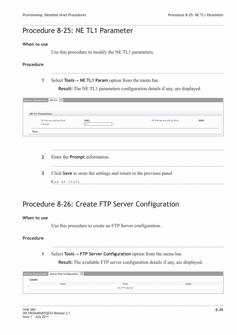
Procedure 8-25: NE TL1 Parameter
When to use
Use this procedure to modify the NE TL1 parameters.
Procedure
...................................................................................................................................................................................................
1 Select Tools→ NE TL1 Param option from the menu bar.
Result: The NE TL1 parameters configuration details if any, are displayed.
...................................................................................................................................................................................................
2 Enter the Prompt information.
...................................................................................................................................................................................................
3 Click Save to store the settings and return to the previous panel.
Procedure 8-26: Create FTP Server Configuration
When to use
Use this procedure to create an FTP Server configuration.
Procedure
...................................................................................................................................................................................................
1 Select Tools→ FTP Server Configuration option from the menu bar.
Result: The available FTP server configuration details if any, are displayed.
Provisioning: Detailed level Procedures Procedure 8-25: NE TL1 Parameter
....................................................................................................................................................................................................................................
....................................................................................................................................................................................................................................
1646 SMC
3KC18036ABABTQZZA Release 2.1
Issue 1 July 2011
8-49
E N D O F S T E P S...................................................................................................................................................................................................

...................................................................................................................................................................................................
2 Click Create to configure the FTP server.
Table 8-19 Create FTP server parameters
Parameter Description
Host Specifies the IP address of the Host machine.
Port Specifies the Port number.
Path Specifies the complete path of the host machine.
...................................................................................................................................................................................................
3 Enter the IP address of the Host machine in text box.
...................................................................................................................................................................................................
4 Enter the Port number.
...................................................................................................................................................................................................
5 Enter the complete path of the host machine.
...................................................................................................................................................................................................
6 Click Save to store the settings and return to the previous panel.
...................................................................................................................................................................................................
7 Click Cancel to revoke all the settings and return to the previous page.
Figure 8-40 Create FTP server
Provisioning: Detailed level Procedures Procedure 8-26: Create FTP Server Configuration
....................................................................................................................................................................................................................................
....................................................................................................................................................................................................................................
8-50 1646 SMC
3KC18036ABABTQZZA Release 2.1
Issue 1 July 2011
E N D O F S T E P S...................................................................................................................................................................................................

Glossary
...................................................................................................................................................................................................................................
A AIS
Alarm Indication Signal failure (Condition Type)
Alarm
Visible or audible signal indicating that an equipment failure or significant event/condition has
occurred.
Alarm Severity
An attribute that defines the priority of the alarm message. The way in which alarms are processed
depends on the severity.
APS
Automatic Protection Switching
...................................................................................................................................................................................................................................
B Backup
The backup and restoration features provide the capability to recover from loss of network
element data because of such factors as human error, power failure, and network element design
flaws.
BITS
Building Integrated Timing Supply
...................................................................................................................................................................................................................................
C CBS
Committed Burst Size is the maximum burst size (byte) with high priority guaranteed for the
Tunnel/Pseudowire packets deliver.
CFM
Connectivity Fault Management
CIF
Customer Interface
CIR
Committed Information Rate is the maximum rate (kb/sec) with high priority guaranteed for the
Tunnel/Pseudowire packets delivery.
....................................................................................................................................................................................................................................
1646 SMC
3KC18036ABABTQZZA Release 2.1
Issue 1 July 2011
GL-1

Circuit
A combination of two transmission channels that permits bidirectional transmission of signals
between two points to support a single communication.
...................................................................................................................................................................................................................................
D DCC
Data Communication Channel
DCN
Data Communication Network.
DDM
Digital Diagnostic Monitoring.
DEI
Dropping Eligibility Indicator
...................................................................................................................................................................................................................................
E ESD
Electro Static Discharge. Static electrical energy potentially harmful to circuit packs and humans.
...................................................................................................................................................................................................................................
F FDB
Filtering Database. The filtering database maintains a dynamic list of paths to which packets are
routed based on the destination address. The database entries are created, updated, and removed
by the learning process.
FLC
First Level Controller
...................................................................................................................................................................................................................................
G GB
Gigabytes.
GUI
Graphical User Interface. This interface supports applications that consist of a series of
rectangular presentation regions called windows. Each window displays another application.
...................................................................................................................................................................................................................................
H HKP
HouseKeeping
...................................................................................................................................................................................................................................
I ID
Identifier
ISID
Backbone Service Identifier
Glossary
....................................................................................................................................................................................................................................
....................................................................................................................................................................................................................................
GL-2 1646 SMC
3KC18036ABABTQZZA Release 2.1
Issue 1 July 2011

ITU
International Telecommunications Union
...................................................................................................................................................................................................................................
L LAC
Local Access Control
LACP
Link Aggregation Control Protocol
LAG
Link Aggregation Group.
LAN
Local Area Network.
Link Aggregation
A method of combining a group of IEEE 802.3 Ethernet links into a single logical link of up to the
aggregate rate.
...................................................................................................................................................................................................................................
M MA
Maintenance Association.
MAC
Media Access Control.
MD
Maintenance Domain.
MEG
Maintenance Entity Group.
MEP
Maintenance association End Point.
MHF
MIP Half Function
MIP
MEG Intermediate Point.
MP
Maintenance Point.
MTU
Maximum Transmission Unit.
Glossary
....................................................................................................................................................................................................................................
....................................................................................................................................................................................................................................
1646 SMC
3KC18036ABABTQZZA Release 2.1
Issue 1 July 2011
GL-3

...................................................................................................................................................................................................................................
N NE
Network Element. A node in a telecommunication network that supports network transport
services and is directly manageable by a management system.
NIF
Network Interface.
Node
A node or network element is defined as all equipment that is controlled by one-system controller.
NTP
Network Time Protocol.
...................................................................................................................................................................................................................................
O OSS
Operational Support System.
OSTYPE
Operations System Type.
...................................................................................................................................................................................................................................
P Path
A logical connection between the point at which a standard frame format for the signal at the
given rate is assembled, and the point at which the standard frame format for the signal is
disassembled.
PBS
Peak Burst Size is the maximum burst rate allowed (byte) for the Tunnel/Pseudowire.
PDU
Power Distribution Unit.
PIP
Provider Instance Port. The set of Virtual Instance ports that are supported by a single instance of
the Internal sub-layer service.
PIR
Peak Information Rate.
PRC
Primary Reference Clock.
...................................................................................................................................................................................................................................
R Ring
A configuration of nodes comprised of network elements connected in a circular fashion. Under
normal conditions, each node is interconnected with its neighbor and includes capacity for
transmission in either direction between adjacent nodes.
Glossary
....................................................................................................................................................................................................................................
....................................................................................................................................................................................................................................
GL-4 1646 SMC
3KC18036ABABTQZZA Release 2.1
Issue 1 July 2011
...................................................................................................................................................................................................................................
S S-VID
Service VLAN Identifier.
SFP
Small Form Factor Pluggable.
Shelf
Basic rack assembly unit; contains subassemblies (usually circuit packs, also referred to as
modules).
SNCP
Sub-Network Connection Protection.
SSM
Synchronization Status Message.
...................................................................................................................................................................................................................................
T TDM
Time Domain Multiplexing.
...................................................................................................................................................................................................................................
U UNI
User-Network Interface.
...................................................................................................................................................................................................................................
V VCG
Virtual Concatenation Group.
VID
Virtual LAN Identifier
VLAN
Virtual Local Area Network.
...................................................................................................................................................................................................................................
X XFP
Extended Form-factor Pluggable.
...................................................................................................................................................................................................................................
Z ZIC
Zero Installation Craft Terminal. A NE-embedded graphical user interface application for local
operation and maintenance.
Glossary
....................................................................................................................................................................................................................................
....................................................................................................................................................................................................................................
1646 SMC
3KC18036ABABTQZZA Release 2.1
Issue 1 July 2011
GL-5

Glossary
....................................................................................................................................................................................................................................
....................................................................................................................................................................................................................................
GL-6 1646 SMC
3KC18036ABABTQZZA Release 2.1
Issue 1 July 2011

Index
A alarm, 6-1
condition log, 6-6
cutoff, 6-4
provision, 6-1
resynch., 6-5
ASAP list, 4-16
audit, 7-12
.............................................................
B bridge
configure, 4-13
.............................................................
C color profile, 4-11
conventions, xxiii
.............................................................
D DB management
cancel remote file copy, 8-13
remote file copy, 8-10
documentation
set, xxiii
.............................................................
E ethernet
P2P XC, 4-34
.............................................................
I IP routing, 8-27
.............................................................
L LAC, 8-16
LAG, 8-35
configure, 8-37
create, 8-35
linear MSP, 8-31, 8-33
log settings, 7-15
.............................................................
M MAC, 8-18
MAC ACL, 4-8
.............................................................
N NTP, 8-19
.............................................................
O OAM
global setting, 4-14, 4-18, 4-25,
4-26, 4-28, 4-29, 4-30, 4-31,
4-32
MA, 4-20
MD, 4-19
MEP, 4-23
.............................................................
S security, 7-1
site identifier, 8-15
software version, 8-4
synchronization, 5-1
BITS-0, 5-2
BITS-OUT, 5-3
outgoing, 5-12
system
log in, 8-2
log out, 8-3
.............................................................
T traffic descriptor, 4-2, 4-5
.............................................................
U user
change account, 7-5
change password, 7-2
create account, 7-4
information, 7-2
modify settings, 7-8
.............................................................
V VCn cross-connection, 8-6
VLAN profile, 4-10
....................................................................................................................................................................................................................................
1646 SMC
3KC18036ABABTQZZA Release 2.1
Issue 1 July 2011
IN-1

Index
....................................................................................................................................................................................................................................
....................................................................................................................................................................................................................................
IN-2 1646 SMC
3KC18036ABABTQZZA Release 2.1
Issue 1 July 2011