3m electrical products 2012 ¼ÅÔµÀ ѳ± ìä¿¿ éÒ 3àÍ...
TRANSCRIPT

3M Electrical Products 2012¼ÅÔµÀѳ±ìä¿¿éÒ 3àÍçÁ
Electrical
You Can Rely On
www.3M.com/th
Contents
Electrical Tape 1
Wire Connector 5
Direct Bury 5
ScotchlokTM 6
Low Voltage Resin Splice 7
PST Cold Shrink 10
Heat Shrink Tubing 11
Medium Voltage Termination 12
Medium Voltage Splice 15
Separable Connectors 17
Lugs & Connectors 21
Accessories 23
Aerosol 28
Insulating and Splicing Tapesà·»·Õèãªé¾Ñ¹à¾×èÍà»ç¹©¹Ç¹
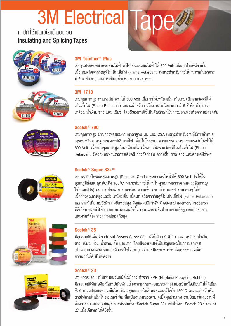
3M TemflexTM Plus
à·»ÃØè¹»ÃÐËÂÑ´ÊÓËÃѺ§Ò¹ä¿¿éÒ·ÑèÇä» ·¹áç´Ñ¹ä¿¿éÒä é 600 Volt à¹×éÍ¡ÒÇäÁèà˹ÕÂÇàÂÔéÁ à¹×éÍà·»¼ÅÔµ¨Ò¡ÇÑÊ´Ø·ÕèäÁèà»ç¹àª×éÍä¿ (Flame Retardant) àËÁÒÐÊÓËÃѺ¡ÒÃãªé§Ò¹ÀÒÂã¹ÍÒ¤ÒÃÁÕ 6 ÊÕ ¤×Í ´Ó, á´§, àËÅ×ͧ, ¹éÓà§Ô¹, ¢ÒÇ áÅÐ à¢ÕÂÇ
3M 1710
à·»¤Ø³ÀÒ¾ÊÙ§ ·¹áç ѹ俿éÒä é 600 Volt à¹×éÍ¡ÒÇäÁèà˹ÕÂÇàÂÔéÁ à¹×éÍà·»¼ÅÔµ¨Ò¡ÇÑÊ Ø·ÕèäÁèà»ç¹àª×éÍä¿ (Flame Retardant) àËÁÒÐÊÓËÃѺ¡ÒÃãªé§Ò¹ÀÒÂã¹ÍÒ¤Òà ÁÕ 6 ÊÕ ¤×Í ´Ó, á´§, àËÅ×ͧ, ¹éÓà§Ô¹, ¢ÒÇ áÅÐ à¢ÕÂÇ â´ÂÊբͧ෻ãªéà»ç¹ÊÑ-Åѡɳì㹡Òú͡à¿Êà¾×èͤÇÒÁ»ÅÍ´ÀÑÂ
Scotch 790
à·»¤Ø³ÀÒ¾ÊÙ§ ¼èÒ¹¡Ò÷´ÊͺµÒÁÁҵðҹ UL áÅÐ CSA àËÁÒÐÊÓËÃѺ§Ò¹·ÕèÁÕ¡ÒáÓ˹´ Spec. ËÃ×ÍÁҵðҹ¢Í§à·»¾Ñ¹ÊÒÂä¿ àªè¹ ã¹âç§Ò¹ÍصÊÒË¡ÃÃÁµèÒ§æ ·¹áç ѹ俿éÒä´é600 Volt à¹×éÍ¡ÒǤسÀÒ¾ÊÙ§ äÁèà˹ÕÂÇàÂÔéÁ à¹×éÍà·»¼ÅÔµ¨Ò¡ÇÑÊ´Ø·ÕèäÁèà»ç¹àª×éÍä¿ (Flame Retardant) ÁÕ¤ÇÒÁ·¹·Ò¹µèÍ¡ÒÃàÊÕ´ÊÕ ¡ÒáѴ¡Ãè͹ ¤ÇÒÁª×é¹ ¡Ã´ ´èÒ§ áÅÐÊÒÃà¤ÁÕµèÒ§æ
Scotch 35
ÁդسÊÁºÑµÔàªè¹à´ÕÂǡѺ෻ Scotch Super 33+ ÁÕãËéàÅ×Í¡ 9 ÊÕ ¤×Í á´§, àËÅ×ͧ, ¹éÓà§Ô¹, ¢ÒÇ, à¢ÕÂÇ, Áèǧ, ¹éÓµÒÅ, ÊéÁ áÅÐà·Ò â´ÂÊբͧ෻ãªéà»ç¹ÊÑ-Åѡɳì㹡Òú͡à¿Êà¾×èͤÇÒÁ»ÅÍ´ÀÑ ·¹áʧÍÑŵÃÒäÇâÍàŵ(UV) áÅÐÁÕ¤ÇÒÁ·¹·Ò¹µèÍÊÀÒÇÐáÇ´ÅéÍÁÀÒ¹͡ä´é´Õ ÊÕäÁè«Õ´¨Ò§
Scotch Super 33+TM
à·»¾Ñ¹ÊÒÂ俪¹Ô´¤Ø³ÀÒ¾ÊÙ§ (Premium Grade) ·¹áç ѹ俿éÒä é 600 Volt ãªéä´éã¹ÍسËÀÙÁÔµÑé§áµè -18 C ¶Ö§ 105 C àËÁÒСѺ¡ÒÃãªé§Ò¹ã¹·Ø¡ÊÀÒ¾ÍÒ¡ÒÈ ·¹áʧÍÑŵÃÒ-äÇâÍàŵ(UV) ·¹¡ÒÃàÊÕ´ÊÕ ¡ÒáѴ¡Ãè͹ ¤ÇÒÁª×é¹ ¡Ã´ èÒ§ áÅÐÊÒÃà¤ÁÕµèÒ§æ ä é´Õ à¹×éÍ¡ÒǤسÀÒ¾ÊÙ§áÅÐäÁèà˹ÕÂÇàÂÔéÁ à¹×éÍà·»¼ÅÔµ¨Ò¡ÇÑÊ´Ø·ÕèäÁèà»ç¹àª×éÍä¿ (Flame Retardant) ¹Í¡¨Ò¡¹Õéà¹×éÍà·»ÂѧÁÕ¤ÇÒÁÂ×´ËÂØè¹ÊÙ§ ÁդسÊÁºÑµÔ¡Òä׹µÑǢͧ෻ (Memory Property) ·Õè´ÕàÂÕèÂÁ ªèÇ·ÓãËé¡Òþѹ෻ÃÑ´á¹è¹ÂÔ觢Öé¹ àËÁÒÐÍÂèÒ§ÂÔè§ÊÓËÃѺ§Ò¹·ÕèÍÂÙèÀÒ¹͡ÍÒ¤ÒÃáÅЧҹ·Õèµéͧ¡ÒäÇÒÁ»ÅÍ´ÀÑÂÊÙ§
3M Electrical Tape
Scotch 23
à·»ÂÒ§ÅÐÅÒ à»ç¹à·»©¹Ç¹ª¹Ô´äÁèÁÕ¡ÒÇ ·Ó¨Ò¡ EPR (Ethylene Propylene Rubber) ÁդسÊÁºÑµÔ¾ÔàÈɤ×Íà¹×éÍà·»àÁ×è;ѹáÅéǨÐÊÒÁÒöËÅÍÁ»ÃÐÊÒ¹µÑÇàͧà»ç¹à¹×éÍà´ÕÂǡѹä´é´ÕàÂÕèÂÁ ¨Ö§ÊÒÁÒö»éͧ¡Ñ¹¤ÇÒÁª×é¹ã¹ºÃÔàdz¨Ø´µèÍÊÒÂä é´Õ ·¹ÍسËÀÙÁÔä é¶Ö§ 130 C àËÁÒÐÊÓËÃѺ¾Ñ¹ÊÒÂä¿ÀÒÂã¹»ÑêÁ¹éÓ ÁÍàµÍÃì ¾Ñ¹à¾×èÍà»ç¹©¹Ç¹¢Í§ÊÒÂà¤àºÔéÅ·Ø¡»ÃÐàÀ· §Ò¹ºÑʺÒÃìáÅЧҹ·Õèµéͧ¡ÒäÇÒÁ»ÅÍ´ÀÑÂÊÙ§ ¤Çþѹ·Ñº´éÇ Scotch Super 33+ à¾×èÍãËéà·» Scotch 23 »ÃÐÊÒ¹à»ç¹à¹×éÍà´ÕÂǡѹä´é´ÕÂÔ觢Öé¹
1

2
Scotch 24 Electrical Shielding Tape
·Í´éÇÂàÊé¹ÅÇ´·Í§á´§ÍÒº´ÕºØ¡àºÍÃì 36 AWG ·Ñé§ËÁ´ ãªé·Ó Shield ·Ò§ä¿¿éÒ ãªé¾Ñ¹ªèͧ·Õèà»ç¹Ã͵èͧ͢à¤àºÔÅà´ÔÁ ËÃ×Íãªé¾Ñ¹à»ç¹¼ÔǵÑǹÓä¿¿éÒÃÙ»·Ã§¡ÃÇ à¾×èÍÅ´¤ÇÒÁà¢éÁ¢Í§àÊé¹áç俿éÒ
InsulateI lProtect&
Scotch 13 Electrical Semi Conducting Tape
à·»ª¹Ô´¡Ö觵ÑǹÓä¿¿éÒ »ÃСͺ´éÇÂÇÑÊ´ØËÅÑ¡¤×Í EPR (Ethylene Propylene Rubber)ÊÒÁÒöÃÑ¡ÉҤسÊÁºÑµÔ¡ÒÃãªé§Ò¹ÍÂÙèä´éáÁéÍسËÀÙÁÔ¨ÐÊÙ§¶Ö§ 130 C à·»·Ó˹éÒ·ÕèÅ´¤ÇÒÁà¢éÁ¢Í§Ê¹ÒÁä¿¿éÒ·Õèà¡Ô´¢Ö鹺ÃÔàdzãµé Shield ·Õè¾Ñ¹ËØéÁÃ͵èÍ áÅÐ Shield ·Õè¾Ñ¹ËØéÁ»ÅÒÂÊÒÂà¤àºÔÅáçÊÙ§ áÅÐÅ´¤ÇÒÁà¢éÁʹÒÁä¿¿éÒºÃÔàdzÃͺæËÑǵèÍÊÒÂáÅТÑéÇ»ÅÒÂÊÒÂà¤àºÔÅáçÊÙ§
Corrosion Protection Tapesà·»·Õèãªé¾Ñ¹·èÍàËÅç¡à¾×èÍ»éͧ¡Ñ¹Ê¹ÔÁ
Scotch 50 áÅÐ 51 à»ç¹à·»·Õèãªé㹧ҹ¾Ñ¹·èÍàËÅç¡à¾×èÍ»éͧ¡Ñ¹¡ÒÃà¡Ô´Ê¹ÔÁáÅСÒáѴ¡Ãè͹¢Í§¡Ã´- èÒ§ áÅÐÊÒÃà¤ÁÕµèÒ§æ
ScotchrapTM Pipe Primer
ãªé¤Ùè¡Ñºà·»àºÍÃì 50 áÅÐ 51 â´Âãªé·ÒÃͧ¾×é¹âÅËÐáÅзèÍàËÅç¡ à¾×èÍàµÃÕÂÁ¾×é¹¼ÔÇãËé¼ÔÇ˹éҢͧâÅËÐàÃÕºáÅÐà¾ÔèÁáçÂÖ´¢Í§à¹×éÍà·»ãËé´ÕÂÔ觢Öé¹
Scotch 22 Heavy Duty Vinyl Tape
à»ç¹à·»·ÕèÁÕ¤ÇÒÁà˹ÕÂÇáÅз¹·Ò¹à»ç¹¾ÔàÈÉ Ë¹Ò 10 mils ÁÕ¤ÇÒÁ·¹·Ò¹·Ñ駴éÒ¹·Ò§¡ÅáÅзҧ俿éÒ à¾×èÍãªéà»ç¹©¹Ç¹ä¿¿éÒÊÓËÃѺ§Ò¹Ë¹Ñ¡ ·¹µèÍáç¡ÃÐá·¡áÅТѴ¶Ù
Scotch 70 Self-fusing Silicone Rubber Tape
ÊÒÁÒö·¹ÍسËÀÙÁÔÊÙ§ä´éÁÒ¡¶Ö§ÃдѺ Class H (180 C) à·»»ÃСͺ´éÇÂÊÒà Inorganic Silicone ·Õè¼èÒ¹¡ÒÃͺÍÂèÒ§àµçÁ·Õè µÑÇà·»©Òº´éÇÂÊÒà Silicone ·ÕèÁդسÊÁºÑµÔÂÖ´µÔ´¡Ñ¹ä´é´éÇÂáç¡´ áÅÐÊÒÁÒöËÅÍÁ»ÃÐÊÒ¹µÑÇàͧà»ç¹à¹×éÍà´ÕÂǡѹä´é

à·»·Õèãªé¡Ñ¹¤ÇÒÁª×é¹áÅÐà»ç¹©¹Ç¹
Sealing and Insulating Tapes
ScotchfilTM
Ê¡ç͵ªì¿ÔÅTM à»ç¹à·»·ÕèËÅÍÁÅÐÅÒÂà»ç¹à¹×éÍà´ÕÂǡѹä´é à¹×éÍà·»Íè͹¹ÔèÁáÅÐÂ×´ËÂØè¹ ãªé¾Ñ¹ËÃ×;͡ºÃÔàdz¾×é¹¼ÔÇ·Õè¢ÃØ¢ÃÐ äÁèÊÁèÓàÊÁÍ àªè¹ ºÃÔàdz Bolt áÅÐ Bus Bar ãËéàÃÕº¢Öé¹ ÃÇÁ·Ñé§ãªé¾Ñ¹à¾×èÍ»éͧ¡Ñ¹¤ÇÒÁª×é¹áÅÐà»ç¹©¹Ç¹ä´é¶Ö§ÃдѺáç´Ñ¹ 600 Volt ÍÕ¡´éÇÂ
Scotch 2200 áÅÐ 2210 à»ç¹à·»·ÕèÁÕÊèǹ¼ÊÁ¢Í§ Mastic áÅÐ Vinyl ÍÂÙè´éÇ¡ѹ ÁդسÊÁºÑµÔà´è¹ã¹¡Òûéͧ¡Ñ¹¤ÇÒÁª×鹺ÃÔàdz¨Ø´µèͧ͢ÊÒÂä¿ä´éÍÂèÒ§´ÕàÂÕèÂÁ àËÁÒСѺ¨Ø´µèͷҧ俿éÒ·ÕèÍÂÙè¹Í¡ÍÒ¤Ò÷ء»ÃÐàÀ· àªè¹ ¨Ø´µèÍã¹â¤ÁÊèͧÊÇèÒ§¢Í§¶¹¹
Scotch 2228 à»ç¹à·»·ÕèÁÕÊèǹ¼ÊÁ¢Í§ EPR (Ethylene Propylene Rubber) áÅÐ Mastic ÍÂÙè´éÇ¡ѹ ãªéä´é´Õ㹡Òþѹà¾×èÍà»ç¹©¹Ç¹áÅлéͧ¡Ñ¹¤ÇÒÁª×鹢ͧ Bus Bar ËÃ×ͨشµèͷҧ俿éÒ·ÕèÁÕáç´Ñ¹äÁèà¡Ô¹ 35 kV. ÃÇÁ·Ñé§ÂѧàËÁÒСѺ¡ÒþѹºÃÔàdz¾×é¹¼ÔÇ·Õè¢ÃØ¢ÃÐ äÁèÊÁèÓàÊÁÍ
à·»¼éÒãÂá¡éÇGlass Cloth Tapes
Scotch 27
à·»¼éÒãÂá¡éǼèÒ¹¡ÃÃÁÇÔ¸Õ Thermosetting ãªéà»ç¹©¹Ç¹ä¿¿éÒ·ÕèÊÒÁÒö·¹ÍسËÀÙÁÔä´éÊÙ§¶Ö§ 130 C (Class B) àËÁÒÐÊÓËÃѺÍØ»¡Ã³ìä¿¿éÒµèÒ§æàªè¹¢´ÅÇ´ ÊÒÂä¿ ¨Ø´µèÍÊÒ ã¹ÊÀÒÇÐáÇ´ÅéÍÁ·ÕèÁÕ¤ÇÒÁÃé͹ÊÙ§ àªè¹àµÒËÅÍÁ ÁÍàµÍÃì à¹×éÍà·»ÁÕ¤ÇÒÁá¢ç§áç·¹µèÍ¡Òâմ¢èǹ àÊÕ´ÊÕ
Scotch 69
à·»¼éÒãÂá¡éÇ ãªéà»ç¹©¹Ç¹ä¿¿éÒ·ÕèÊÒÁÒö·¹ÍسËÀÙÁÔä´éÊÙ§¶Ö§ 200 C (Class H) àËÁÒÐÊÓËÃѺãªé¾Ñ¹ Coil ¢Í§ËÁéÍá»Å§áÅÐÁÍàµÍÃì
The choice of moreProfessional
Electricians3

Spec
ial T
apes
3M Electrical Tape Chart
Product DescriptionTape
ThicknessSize
AvailableTemperature
RatingTypical Applications
Scotch Super 33+TM
Premium Vinyl Electrical Tape
Scotch 35 Color Coding Tape
Highly conformable in all weatherapplications: resista UV rays, abrasion,
corrosion, alkalies & acids. Flame retardant UL listed. CSA certified
9 fade resistant colors, excellentinsulating properties. Resist UV rays, abrasion, corrosion, alkalies & acid.
7 mil Primary insulationfor splices up to 600V.
Protective jacketing.
3/4" x 66'
7 mil Phase identification& marking.Harnessing.
3/4" x 66'
Scotch 22 Heavy Duty Vinyl Electrical Tape
Thicker for increased mechanicalstrength, abrasion resistant. UL listed.
CSA certified. Electrical insulating.
10 mil Bus bar insulation.Cable jacket repaire.
1 1/2" x 36yards
Rubber tape, Semi conductive.Compatible with cable semi-conducting
jackets.
30 mil Electrically round highvoltage connections.Provide cable shield
continuation.
3/4"x 15'
High & low voltage insulating,self-fusing rubber tape
30 mil Primary electricalinsulation for splicing
all solid dielectriccable through 69kV
3/4" x 30'3/4'' x 6'
All metal open weave shielding braid,conformable, temperature stable.
Continue electrostaticshielding across splice.
1" x 15'
1" x 30'Arc & track resistant; self fusing,long lasting silicone rubber
Protective overwrapfor terminating high
voltage cables.
12 mil
1 1/2" x 60"
1 1/2" x 60"
ScotchfilTM Electrical Insulation Putty
Black, self-fusing, insulatingputty in tape form.
Self-fusing rubber based compoundbonded to a moisture sealing mastic;
all weather
Insulate connections upto 600V. Smooth bus
bar irregularities.
Insulate, pad ansseal bus bar and splice
connections
125 mil
65 mil
ScotchrapTM 50 and 51 All Weather Corrosion Protection Tapes
All weather performanceand corrosion resistance.
Resistant to impact & abrasions
50 is 10 mil51 is 20 mil
Corrosion protectionon pipes, conduits
& fittings, etc.
1" x 100'2" x 100'4" x 100'6" x 100'
ScotchrapTM
Pipe PrimerQuick dry, non-sag rubber base
primer that prepares metal surfacesfor tape application
1 galloncan
For use withScotchrapTM 50 & 51
tapes & Temflex1100 Tape
Product Name
Viny
l Ins
ulat
ion
Tape
s Co
rros
ion
Prot
ectio
n Ta
pes
Splic
ing
Tape
s
105 C220 F
105 C220 F
80 C176 F
80 C176 F
80 C176 F
80 C176 F
80 C176 F
Continuous: 90 C/194 FShort term:
130 C/266 F
Continuous: 90 C/194 FShort term:
130 C/266 F
180 C356 F
80 C176 F
80 C176 F
3M TemflexTM PlusGeneral purpose vinyl insulating tape.
Excellent resistance to; abrasion,corrosion, alkalies & acids. Flameretardant and memory property.
0.125 mm.(5 mil)
3/4"x 10 m. Primary insulationfor splices up to
600V.
Primary insulationfor splices up to
600V.
3M 1710 General purpose vinyl insulating tape.Excellent resistance to; abrasion,
corrosion, alkalies & acids.Flame retardant and Memory property.
General purpose vinyl insulating tape.excellent resistance to: abrasion,
moisture, alkalies, acid and varyingweather conditions (including sunlight).
UL Listed and CSA certified
0.175 mm.(7 mil)
3/4" x 10 m.
Primary insulationfor splices up to
600V.
0.175 mm.(7 mil)
3/4" x 20 m.
4
Scotch 790
Scotch 13 Semiconducting Tape
Scotch 23 Rubber Tape
Scotch 24Shielding Tape
1/2" x 66'3/4" x 66'
1'' x 36 Yards
Scotch 27 and 69 Glass Cloth tape
Woven insulating glass cloth: hightemperature resistance;
high mechanical strength UL Recognized
Continue electrostaticshielding across
splice.
27 is 7 mil69 is 7.5 mil
27 is Class B temp(130 C/266 F)
69 is class H temp(200 C/392 F)
Scotch 70 Self-Fusing Silicone Rubber Tape
Scotch 2228Rubber Mastic Tape
194 F (90 C) emergencyoverload of 266 F
(130 C)

â¤Ã§ÊÃéÒ§¢Í§ Performance Plus »ÃСͺ´éÇ 3 Êèǹ ä´éá¡è
1. Insulation ·Ó´éǾÅÒʵԡ·ÕèÁÕ¤ÇÒÁÂ×´ËÂØè¹ä´é´Õ äÁèᵡÃéÒÇ Insulation ÁÕ¤ÇÒÁÂÒÇ¡ÇèÒ Wire Nut ·ÑèÇä» ªèÇÂãËé¡ÒõԴµÑé§ÊдǡáÅÐ ªèÇÂà¾ÔèÁ¤ÇÒÁà»ç¹©¹Ç¹ ÁÕÃٻẺ·Õè¶Ù¡Í͡ẺÁÒà»ç¹¤ÃÕº»ÅÒ ¨Ö§ªèÇÂãËéÊдǡ㹡ÒèѺËÁع§èÒ »Õ¡´éÒ¹ÅèÒ§¹ÔèÁ ªèÇÂãËéâ¤é§ÊÒÂãËé §Íä´é ªèÇ»ÃÐËÂÑ´à¹×éÍ·Õè㹡ÒÃãªé§Ò¹ã¹¾×é¹·Õè¨Ó¡Ñ´2. Steel Inner Shell ¤×Í»ÅÍ¡àËÅç¡·Õè¤Çº¤ØÁ ¡ÒÃÂ×´áÅÐË´¢Í§Ê»ÃÔ§ àÁ×èÍÁÕ¡ÒÃà»ÅÕè¹á»Å§ ¢Í§ÍسËÀÙÁÔã¹á¡¹ ·Í§á´§3. Spring Grip ä´éÃѺ¡Òà Í͡ẺãËéÁÕ¤ÇÒÁá¢ç§áçáÅÐÁÕáçÂÖ´à¡ÅÕÂÇàÊé¹ÅÇ´ ÊÒÁÒöÂÖ´à¡ÒÐä´é´Õ äÁèÇèÒàÇÅÒÂ×´ËÃ×ÍË´ áÅÐä´é¼èÒ¹ ¡ÒÃà¤Å×ͺà¾×èÍ»éͧ¡Ñ¹¡ÒÃà¡Ô´Ê¹ÔÁáÅéÇ
Performance
5
à»ç¹ÍØ»¡Ã³ìµèÍÊÒÂä¿·ÕèÁÕ»ÅÍ¡©¹Ç¹·Ó¨Ò¡
¾ÅÒʵԡ ÁÕ¤ÇÒÁÂ×´ËÂØè¹áÅзӧҹâ´ÂÍÒÈÑÂ
áçºÕº¢Í§Ê»ÃÔ§ ãªéµèÍÊÒÂä¿¿éÒÀÒÂã¹ÍÒ¤ÒÃ
ºéÒ¹¾Ñ¡ÍÒÈÑ áÅÐÊÒÂà¢éÒâ¤Áä¿ ·Õèáç´Ñ¹äÁèà¡Ô¹
1,000 âÇÅµì ·Ñ駪¹Ô´ÊÒÂá¢ç§áÅÐÊÒÂà¡ÅÕÂÇ·ÕèÁÕ¢¹Ò´µÑé§áµè 0.5-10 Sq.mm. ÁÕÊ»ÃÔ§µÔ´ÍÂÙè¡Ñº»ÅÍ¡àËÅç¡¡ÅéÒáÅЩ¹Ç¹·Õè
Â×´ËÂØè¹ ÊÒÁÒöÃÑ´ÊÒÂä¿ä´éá¹è¹ â´ÂÁÑè¹ã¨ä´éÇèÒ¨ÐäÁè¤ÅÒµÑÇÍÍ¡ã¹ÀÒÂËÅѧ ãªé§Ò¹§èÒ à¾Õ§ÊÇÁà¢éҡѺÊÒ·ͧᴧ
áÅÐËÁع ÊÒ¨еÕà¡ÅÕÂÇà¢éÒËҡѹâ´ÂÍѵâ¹ÁÑµÔ ·¹ÍسËÀÙÁÔä´é¶Ö§ 105 C ä´éÃѺÁҵðҹ UL486C File No.E23438,
CSA Certified áÅÐÁդسÊÁºÑµÔäÁèà»ç¹àª×éÍä¿ÅÒÁ (Flame Retardant)
Spring Connectors
Spring Connectors
Plus
3M Direct Bury Splice kit
ªØ´µèÍÊÒÂä¿ÊÓËÃѺ½Ñ§´Ô¹ àËÁÒÐÊÓËÃѺàª×èÍÁµèÍÊÒÂä¿·ÕèÁÒ¡¡ÇèÒ 2 àÊé¹¢Öé¹ä» ÊÓËÃѺ§Ò¹Ãкºä¿ÊèͧÊÇèÒ§ ËÃ×ͧҹÃкº¤Çº¤ØÁä¿¿éÒ
ä´éÃѺÁҵðҹ ULListed ULStandard 486D, File No.102356 ROHS 2002/95/ECCertificate
㹪شä´éÃÇÁÊ»ÃÔ§¤Í¹à¹¤àµÍÃì·ÕèÁդسÊÁºÑµÔäÁèà»ç¹àª×éÍä¿ (Flame RetardantInsulator), Prolypropylene Tube áÅÐ Sealant ÊÓËÃѺ¡Ñ¹¹éÓËÃ×ͤÇÒÁª×é¹1 kit ÁÕ 2 Connectors
Direct Bury splice and effectivey moisture seal two or more conductorsfor remote control circuits in irregation and landscape lighting system.
B/G+ R/Y+ T/Y+
Product No. Wire Range (Qty # Size) Voltage Max.OperatingTemperature
ReplaceModel
DBR/Y-6 600 V2-7#1.5mm2, 2-5#2.5mm2, 2-4#4mm2, 2#6mm2
DBO/B-6 600 V 105 C DBY
DBR
3-6#0.75mm2 2-4#1.5mm2, 2-3#2.5mm2
105 C
T/Y+ 600 V 2-6#0.5mm2, 105 C 100 Scotchlok
2-4#1.0-1.5mm2, Y
3#2.5mm2
R/Y+ 600 V 2-7#1.5mm2, 105 C 100 Scotchlok
2-5#2.5mm2, R
2-4#4mm2, 2#6mm2
B/G+ 600 V 3-6#2.5mm2, 105 C 50 Scotchlok
2-5#4mm2, B, G
2-4#6mm2, 2#10mm2
ConnectorMaximumVoltageRating
Wire Range(Qty # Size)
MaxOperating
Temperature
Qty / Box Replaced
6
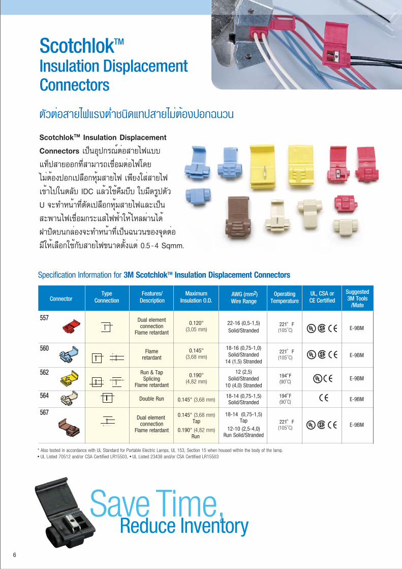
ScotchlokTM Insulation Displacement Connectors à»ç¹ÍØ»¡Ã³ìµèÍÊÒÂä¿áºº
á·ç»ÊÒÂÍÍ¡·ÕèÊÒÁÒöàª×èÍÁµèÍä¿â´Â
äÁèµéͧ»Í¡à»Å×Í¡ËØéÁÊÒÂä¿ à¾Õ§ãÊèÊÒÂä¿
à¢éÒä»ã¹µÅѺ IDC áÅéÇãªé¤ÕÁºÕº ãºÁÕ´ÃÙ»µÑÇ
U ¨Ð·Ó˹éÒ·ÕèµÑ´à»Å×Í¡ËØéÁÊÒÂä¿áÅÐà»ç¹
Êоҹä¿àª×èÍÁ¡ÃÐáÊä¿¿éÒãËéäËżèÒ¹ä´é
½Ò»Ô´º¹¡Åèͧ¨Ð·Ó˹éÒ·Õèà»ç¹©¹Ç¹¢Í§¨Ø´µèÍ
ÁÕãËéàÅ×Í¡ãªé¡ÑºÊÒÂä¿¢¹Ò´µÑé§áµè 0.5-4 Sqmm.
ScotchlokTM Insulation Displacement Connectors
µÑǵèÍÊÒÂä¿áçµèÓª¹Ô´á·»ÊÒÂäÁèµéͧ»Í¡©¹Ç¹
221 íí F(105 C)
221 íí F(105 C)
221 íí F(105 C)
194 ííF(90 C)
194 ííF(90 C)
Features/Description
5570.120"
(3,05 mm)
560 0.145"(3,68 mm)
562 0.190"(4,82 mm)
5640.145" (3,68 mm)
567 0.145" (3,68 mm)Tap
0.190" (4,82 mm)Run
Specification Information for 3M ScotchlokTM Insulation Displacement Connectors
ConnectorType
ConnectionMaximum
Insulation O.D.AWG (mm2)Wire Range
OperatingTemperature
UL, CSA orCE Certified
Suggested3M Tools
/Mate
* Also tested in accordance with UL Standard for Portable Electric Lamps, UL 153, Section 15 when housed within the body of the lamp. UL Listed 70512 and/or CSA Certified LR15503, UL Listed 23438 and/or CSA Certified LR15503
22-16 (0,5-1,5)Solid/Stranded
18-16 (0,75-1,0)Solid/Stranded
14 (1,5) Stranded
12 (2,5)Solid/Stranded
10 (4,0) Stranded
18-14 (0,75-1,5)Solid/Stranded
18-14 (0,75-1,5)Tap
12-10 (2,5-4,0)Run Solid/Stranded
E-9BM
E-9BM
E-9BM
E-9BM
E-9BM
Reduce InventorySave Time,
Dual elementconnection
Flame retardant
Flameretardant
Run & TapSplicing
Flame retardant
Double Run
Dual element connection
Flame retardant

7
ScotchcastTM à»ç¹ªØ´µèÍÊÒÂà¤àºÔŪ¹Ô´àëԹ ·ÕèÁÕÃкº¡Ò÷ӧҹ
Ẻ»Ô´ (Closed Mix) â´Â·Õè¼ÙéãªéäÁèµéͧÊÑÁ¼Ñʶ١àëԹ àËÁÒСѺ
ÊÒÂä¿ NYY, CV áÅÐ THW ª¹Ô´á¡¹à´ÕÂÇËÃ×ÍËÅÒÂ᡹·ÕèÁÕáç´Ñ¹
ä¿¿éÒäÁèà¡Ô¹ 1kV â´ÂÊÒÁÒö½Ñ§ãµé´Ô¹ (Direct Buried) áÅСѹ¹éÓ
à¢éÒä´éà»ç¹ÍÂèÒ§´Õ â´ÂàëԹÁÕ¤ÇÒÁá¢ç§áçÊÙ§ ÊÒÁÒö¨èÒ¡ÃÐáÊä¿
ä´éÀÒÂã¹ 30 ¹Ò·Õ ÊÒÁÒö·¹µèÍÊÀÒ¾áÇ´ÅéÍÁ·ÕèÁÕÁÅÀÒÇÐÊÙ§
ÃÇÁ·Ñ駡ѹ¡ÒáÃÐá·¡ËÃ×ÍÅÒ¡¶Ùä´é´Õ
·´ÊͺµÒÁÁҵðҹ EN 50383 Table 3 (ÊÓËÃѺ 92-NB Series)
áÅÐ UL Listed 486D (ÊÓËÃѺ 82-A Series)
㹪ش»ÃСͺ´éÇ Transparent Mould, ªØ´¹éÓÂÒ Resin 4 ËÃ×Í 40G
áÅСÃдÒÉ·ÃÒÂËÃ×Í·Õè¢Ñ´à»Å×Í¡ÊÒÂà¤àºÔÅ (äÁèÃÇÁ Connector)
SCOTCHCAST SPLICE KIT 92-NB SERIES / 82-A SERIES
can use for direct buried application to insulate and seal cable
for single or multiple conductor cable type NYY,CV or THW rated
through 1kV, meet requirement of EN 50393 Table 3 (for 92-NB
Series) and UL Listed 486D standard (for 82-A Series) Kit content
are Transparent mould, Resin No.4 or No.40G and Cable Jacket
Cleaning kit 82-A Series
ScotchcastTM Inline Splicing Kits for 0.6/1kV
92-NBA Series
VoltageLow Splice
8
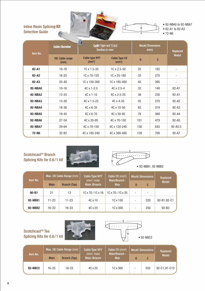
Inline Resin Splicing
Selection Guide
ScotchcastTM Branch
Splicing Kits for 0.6/1 kV
ScotchcastTM Tee
Splicing Kits for 0.6/1 kV
D
C
D
C
C
D
90-B1 21 13 1C x 70 / 1C x 16 1C x 70 / 1C x 35 - -
92-NBB1 11-23 11-23 4C x 10 1C x 150 - 220 92-B1,92-C1
92-NBB2 16-33 16-33 4C x 25 1C x 300 - 250 92-B3
Branch (Tap)Item No.
Max. OD Cable Range (mm) Mould DimensionsCable Type NYY(mm2, max)
Main /Branch
Cable CV (mm2)Main/Branch :
MaxMain CD
ReplacedModel
92-NBC2 16-33 16-33 4C x 25 1C x 300 - 250 92-C1,91-C12
92-NBA0 to 92-NBA782-A1 to 82-A372-N6
Mould Dimensions(mm) Replaced
ModelD C
Cable type NYY(mm2)
Cable Type CV(mm2)
82-A1 10-16 1C x 1.5-35 1C x 2.5-50 25 182 -
82-A2 16-25 1C x 10-120 1C x 25-185 33 270 -
82-A3 25-40 1C x 150-300 1C x 185-400 45 395 -
92-NBA0 10-16 4C x 1-2.5 4C x 2.5-4 32 148 82-A1
92-NBA2 12-25 4C x 1-10 4C x 2.5-25 38 230 92-A1
92-NBA3 13-30 4C x 1.5-25 4C x 4-35 55 270 92-A2
92-NBA4 18-36 4C x 6-35 4C x 10-50 63 319 92-A3
92-NBA5 19-45 4C x 6-70 4C x 50-95 76 369 92-A4
92-NBA6 27-54 4C x 35-95 4C x 70-150 101 479 92-A5
92-NBA7 29-64 4C x 70-150 4C x 120-240 130 643 92-A5.5
72-N6 32-82 4C x 185-240 4C x 300-400 128 700 92-A7
Item No.
OD. Cable range(mm)
Section in mm2
92-NBB1, 92-NBB2
92-NBC2
Branch (Tap)Item No.
Max. OD Cable Range (mm) Mould DimensionsCable Type NYY(mm2, max)
Main /Branch
Cable CV (mm2)Main/Branch :
MaxMain CD
ReplacedModel
9
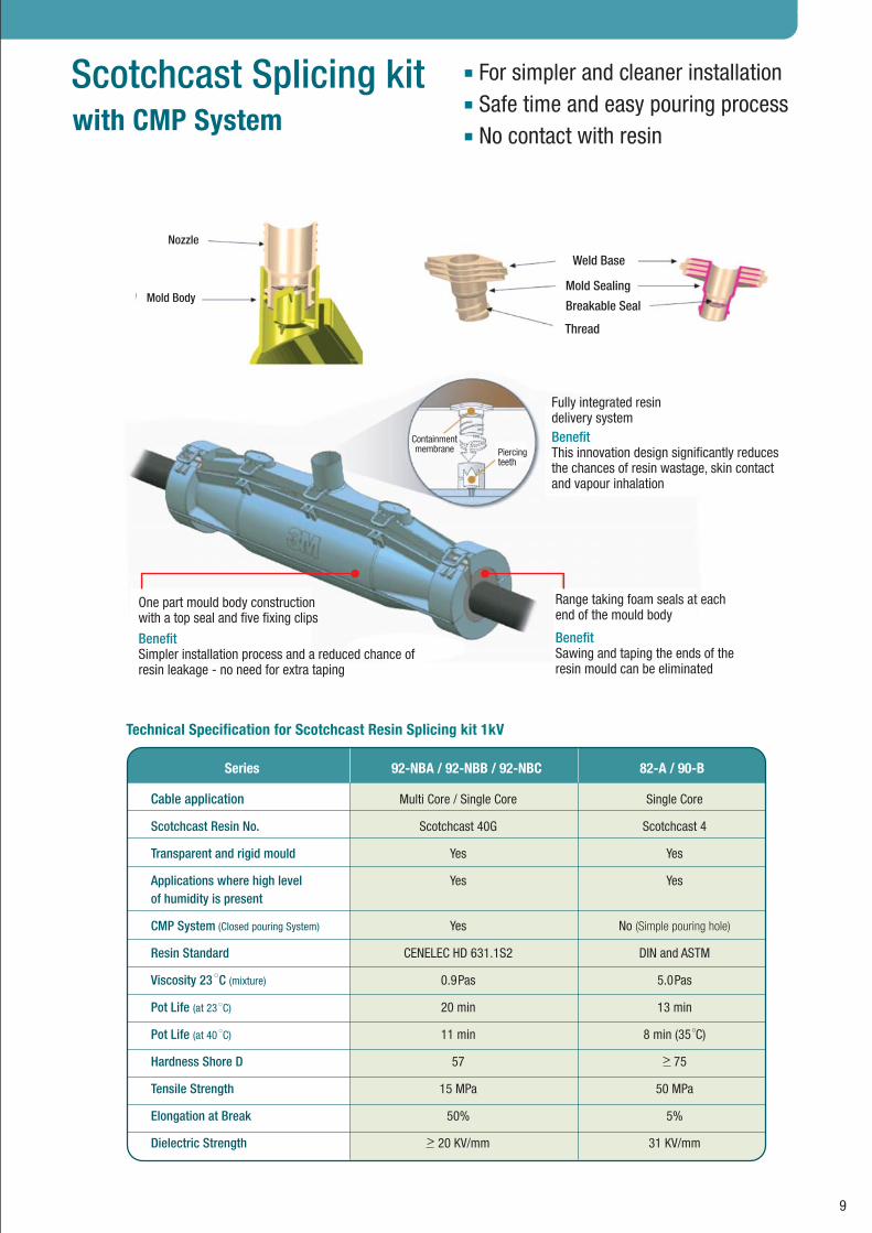
Range taking foam seals at eachend of the mould body
BenefitSawing and taping the ends of theresin mould can be eliminated
Containmentmembrane Piercing
teeth
One part mould body constructionwith a top seal and five fixing clips
BenefitSimpler installation process and a reduced chance of resin leakage - no need for extra taping
Fully integrated resindelivery systemBenefitThis innovation design significantly reducesthe chances of resin wastage, skin contactand vapour inhalation
Technical Specification for Scotchcast Resin Splicing kit 1kV
Nozzle
Mold Body
Weld Base
Mold Sealing
Breakable Seal
Thread
Series 82-A / 90-B92-NBA / 92-NBB / 92-NBC
Cable application Multi Core / Single Core Single Core
Scotchcast Resin No. Scotchcast 40G Scotchcast 4
Transparent and rigid mould Yes Yes
Applications where high level Yes Yesof humidity is present
CMP System (Closed pouring System) Yes No (Simple pouring hole)
Resin Standard CENELEC HD 631.1S2 DIN and ASTM
Viscosity 23 C (mixture) 0.9Pas 5.0Pas
Pot Life (at 23 C) 20 min 13 min
Pot Life (at 40 C) 11 min 8 min (35 C)
Hardness Shore D 57 > 75
Tensile Strength 15 MPa 50 MPa
Elongation at Break 50% 5%
Dielectric Strength > 20 KV/mm 31 KV/mm
For simpler and cleaner installationSafe time and easy pouring processNo contact with resin
with CMP SystemScotchcast Splicing kit

PST Cold ShrinkTM
8420 Series Connector Insulator©¹Ç¹ËØéÁ Connector/Sleeve áÅÐÊÒÂà¤àºÔŪ¹Ô´ Cold ShrinkTM ÊÓËÃѺà¤àºÔŪ¹Ô´ Single Core ·ÕèÁÕÃдѺ
áç´Ñ¹äÁèà¡Ô¹ 1000 Volt ·Ó¨Ò¡ÇÑÊ´ØÂÒ§ EPDM ·Õè»ÃÒȨҡ¤ÅÍäôìáÅЫÑÅà¿ÍÃì ãªéà·¤â¹âÅÂÕ Cold ShrinkTM
«Öè§à»ç¹©¹Ç¹ÂÒ§·Õè¶Ù¡¢ÂÒÂäÇé´éÇÂ᡹¾ÅÒʵԡ àÁ×è͵ԴµÑé§à¾Õ§ÊÇÁËØéÁ Connector/Sleeve áÅÐà¤àºÔÅ áÅéÇ´Ö§
᡹¾ÅÒʵԡÍÍ¡ PST Cold ShrinkTM ¨ÐË´ÃÑ´·Ñ¹·Õ áÅÐÁÕ¢¹Ò´·ÕèàÅç¡á¹º¡Ñºà¤àºÔÅ «Öè§áçºÕºÃÑ´¢Í§ PST
Cold ShrinkTM µèÍà¤àºÔŨÐÊÒÁÒö»éͧ¡Ñ¹¹éÓáÅФÇÒÁª×é¹ä´éà»ç¹ÍÂèÒ§´Õ àËÁÒÐÊÓËÃѺà¤àºÔÅ·ÕèÍÂÙèã¹ Cable
Tray ã¹¾×é¹·Õè¨Ó¡Ñ´ËÃ×ͽѧ´Ô¹ àÁ×è͵ԴµÑé§àÊÃç¨áÅéÇÊÒÁÒö¨èÒ¡ÃÐáÊä¿¿éÒä´é·Ñ¹·Õ PST Cold ShrinkTM
8420 Series ä éÃѺ¡Ò÷´Êͺ¡Òûéͧ¡Ñ¹¹éÓà¢éÒ Ø´µè͵ÒÁÁҵðҹ ANSI C119-1 áÅÐ Western
Underground Guide 214
Specifications and Ordering Information for 1kV Cold Shrink Splices
ProductSeries
Conductor Size(CV Cable)
MinimumCable Diameter
for Seal
MaximumConnector
Length
RelaxedTube Length
MaximumDiameter
Insulator Covers
8424-8 10-16 mm2 0.10" (3 mm) 0.39" (10 mm) 3" (76 mm) 8" (203 mm)
8425-8 25-70 mm2 0.40" (10 mm) 0.82" (21 mm) 3" (76 mm) 8" (203 mm)
8426-11 70-150 mm2 0.51" (13 mm) 1.00" (25 mm) 7" (178 mm) 11" (279.4 mm)
8427-12 120-300 mm2 0.69" (18 mm) 1.30" (33 mm) 8" (203 mm) 12" (305 mm)
8428-18 240-500 mm2 0.95" (24 mm) 1.90" (48 mm) 14" (356 mm) 18" (457 mm)
8429-18 400-630 mm2 1.28" (32.2 mm) 2.50" (67 mm) 14" (76 mm) 18" (457 mm)
Protection for wire and cable splices.Easy-to-install
10
Cold ShrinkTM
11
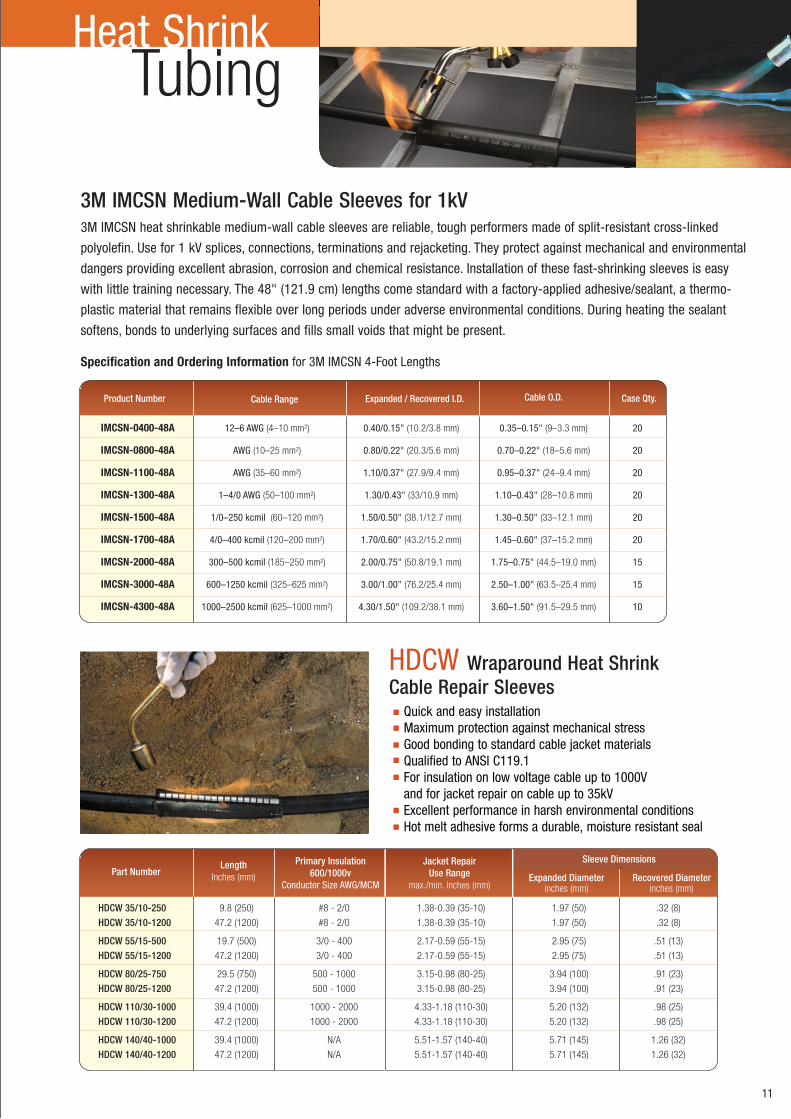
3M IMCSN heat shrinkable medium-wall cable sleeves are reliable, tough performers made of split-resistant cross-linked
polyolefin. Use for 1 kV splices, connections, terminations and rejacketing. They protect against mechanical and environmental
dangers providing excellent abrasion, corrosion and chemical resistance. Installation of these fast-shrinking sleeves is easy
with little training necessary. The 48" (121.9 cm) lengths come standard with a factory-applied adhesive/sealant, a thermo-
plastic material that remains flexible over long periods under adverse environmental conditions. During heating the sealant
softens, bonds to underlying surfaces and fills small voids that might be present.
Heat Shrink
3M IMCSN Medium-Wall Cable Sleeves for 1kV
Tubing
IMCSN-0400-48A 12–6 AWG (4–10 mm2) 0.40/0.15" (10.2/3.8 mm) 0.35–0.15" (9–3.3 mm) 20 IMCSN-0800-48A AWG (10–25 mm2) 0.80/0.22" (20.3/5.6 mm) 0.70–0.22" (18–5.6 mm) 20 IMCSN-1100-48A AWG (35–60 mm2) 1.10/0.37" (27.9/9.4 mm) 0.95–0.37" (24–9.4 mm) 20 IMCSN-1300-48A 1–4/0 AWG (50–100 mm2) 1.30/0.43" (33/10.9 mm) 1.10–0.43" (28–10.8 mm) 20 IMCSN-1500-48A 1/0–250 kcmil (60–120 mm2) 1.50/0.50" (38.1/12.7 mm) 1.30–0.50" (33–12.1 mm) 20 IMCSN-1700-48A 4/0–400 kcmil (120–200 mm2) 1.70/0.60" (43.2/15.2 mm) 1.45–0.60" (37–15.2 mm) 20 IMCSN-2000-48A 300–500 kcmil (185–250 mm2) 2.00/0.75" (50.8/19.1 mm) 1.75–0.75" (44.5–19.0 mm) 15 IMCSN-3000-48A 600–1250 kcmil (325–625 mm2) 3.00/1.00" (76.2/25.4 mm) 2.50–1.00" (63.5–25.4 mm) 15 IMCSN-4300-48A 1000–2500 kcmil (625–1000 mm2) 4.30/1.50" (109.2/38.1 mm) 3.60–1.50" (91.5–29.5 mm) 10
Product Number Cable Range Expanded / Recovered I.D. Cable O.D. Case Qty.
HDCW Wraparound Heat Shrink Cable Repair Sleeves
Quick and easy installationMaximum protection against mechanical stressGood bonding to standard cable jacket materialsQualified to ANSI C119.1For insulation on low voltage cable up to 1000V and for jacket repair on cable up to 35kVExcellent performance in harsh environmental conditionsHot melt adhesive forms a durable, moisture resistant seal
Specification and Ordering Information for 3M IMCSN 4-Foot Lengths
Expanded Diameterinches (mm)
Recovered Diameterinches (mm)
Part NumberLength
Inches (mm)
Primary Insulation600/1000v
Conductor Size AWG/MCM
Jacket RepairUse Range
max./min. inches (mm)
Sleeve Dimensions
HDCW 35/10-250 9.8 (250) #8 - 2/0 1.38-0.39 (35-10) 1.97 (50) .32 (8)
HDCW 35/10-1200 47.2 (1200) #8 - 2/0 1.38-0.39 (35-10) 1.97 (50) .32 (8)
HDCW 55/15-500 19.7 (500) 3/0 - 400 2.17-0.59 (55-15) 2.95 (75) .51 (13)
HDCW 55/15-1200 47.2 (1200) 3/0 - 400 2.17-0.59 (55-15) 2.95 (75) .51 (13)
HDCW 80/25-750 29.5 (750) 500 - 1000 3.15-0.98 (80-25) 3.94 (100) .91 (23)
HDCW 80/25-1200 47.2 (1200) 500 - 1000 3.15-0.98 (80-25) 3.94 (100) .91 (23)
HDCW 110/30-1000 39.4 (1000) 1000 - 2000 4.33-1.18 (110-30) 5.20 (132) .98 (25)
HDCW 110/30-1200 47.2 (1200) 1000 - 2000 4.33-1.18 (110-30) 5.20 (132) .98 (25)
HDCW 140/40-1000 39.4 (1000) N/A 5.51-1.57 (140-40) 5.71 (145) 1.26 (32)
HDCW 140/40-1200 47.2 (1200) N/A 5.51-1.57 (140-40) 5.71 (145) 1.26 (32)

3M Cold Shrink QT-III Terminations offer easy installation and reliable performance when terminating indoor and
outdoor medium voltage power cable rated up to 35kV. The unigue step-core design combined with the built in
Hi-K stress control and silicone sealing componds means simpler installation on all type of cable.
The QT-IIII assures long term reliability through an improved silicone rubber body with enhance hydrophobic recovery.
UV Stabilty and track and erosion resistance. Each termination kit has all of the materials required to make a three
terminations. All terminations meet or exceed IEEE48 requirement.
3M QT-II áÅÐ QT-III à»ç¹ªØ´ËÑǵèÍÊÒÂà¤àºÔÅ (Termination kit) ·ÕèÁÕÃдѺ
áç ѹ俿éÒ 5kV-36kV ¼ÅÔµ¨Ò¡«ÔÅÔ⤹ÃѺàºÍÃì «Öè§ÊÒÁÒö·¹µèÍÊÀÒ¾áç´Ñ¹ä¿¿éÒ·ÕèÊÙ§
ä´éà»ç¹ÍÂèÒ§´Õ áÅÐÁդسÊÁºÑµÔ·Õè¹éÓäÁèà¡Òо×é¹¼ÔǢͧ©¹Ç¹ (Hydrophobic) áÅÐä´éÃѺ¡ÒÃÍ͡ẺãËéÁÕâ¤Ã§ÊÃéÒ§
à»ç¹ªÔé¹à ÕÂǡѹ·Ñé§ËÁ´ ÃÇÁ·Ñé§Êèǹ¤Çº¤ØÁʹÒÁä¿¿éÒ (Stress Control), ¼ÔÇ©¹Ç¹ (Insulator) áÅÐÊèǹ»Õ¡ (Skirt)
«Ö觪èÇÂãËé¡ÒõԴµÑé§à»ç¹ä»ä éÍÂèÒ§ÃÇ´àÃçÇáÅЧèÒ äÁèÂØè§ÂÒ¡ ÃÇÁ·Ñé§Å´¤ÇÒÁ¼Ô´¾ÅÒ´¨Ò¡¡ÒõԴµÑ駴éÇ¡ÒÃãªé
à·¤â¹âÅÂÕ Cold Shrink (¡ÒõԴµÑé§â´ÂäÁèãªé¤ÇÒÁÃé͹) éÇÂÇÔ¸Õ¡Òô֧᡹¾ÅÒʵԡÍÍ¡¨Ò¡ Termination зÓãËé
à¡Ô´áç˴ÃÑ´á¹è¹¡Ñºà¤àºÔŷѹ·Õ (Life Seal) ·ÓãËéäÁèÁÕÍÒ¡ÒÈÀÒÂã¹ËÑǵèÍÊÒÂà¤àºÔÅ à¾×èÍ»éͧ¡Ñ¹¤ÇÒÁª×é¹áÅСÒÃ
ᵡµÑǢͧÍÒ¡ÒȨҡáç ѹ俿éÒÊÙ§ (Air Break Down) ä é 100% â´Â¼èÒ¹Áҵðҹ IEEE48-1990
3M Cold Shrink QT-II Terminations provide easy
installation for a broad spectrum of indoor and outdoor
applications with built-in Hi-K stress relief. The insulators
are pre-stretched around a spiral-wound, plastic core.
When the terminator is slipped over a property
prepared cable and the core is removed. the terminator
immediately shrinks to the cable's dimensions.
The result is a void-free. Flexible seal without special
tools or torches. Meet requirement of IEEE Standated
48-1990 for Class I terminations unless noted.
TerminationMedium Voltage
QT-II 5670-I series, 5640-5650 series
QT-III 7600 Series
12
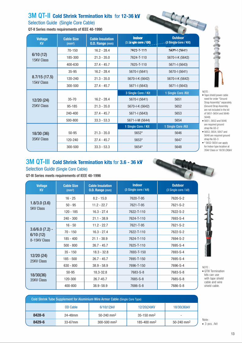
3M QT-III Cold Shrink Termination kits for 3.6 - 36 kSelection Guide (Single Core Cable)
3M QT-II Cold Shrink Termination kits for 12-36Selection Guide (Single Core Cable)
12/20 (24)25KV Class
18/30 (36)35KV Class
35-70 16.2 - 28.4 5670-I (5641) 5651
95-185 21.3 - 35.0 5670-I-K (5642) 5652
240-400 27.4 - 45.7 5671-I (5643) 5653
500-800 33.3 - 53.3 5671-I-M (5644) 5654
50-95 21.3 - 35.0 5652* 5646
120-240 27.4 - 45.7 5653* 5647
300-500 33.3 - 53.3 5654* 5648
70-150 16.2 - 28.4
185-300 21.3 - 35.0 7624-T-110 5670-I-K (5642)
400-630 27.4 - 45.7 7625-T-110 5671-I (5643)
6/10 (12)15KV Class
VoltageKV
Cable Size(mm2)
Cable InsulationO.D. Range (mm)
Outdoor(3 Single core / Kit)
VoltageKV
Cable Size(mm2)
Cable InsulationO.D. Range (mm)
16 - 25 8.2 - 15.0 7620-T-95 7620-S-2
50 - 95 11.2 - 22.7 7621-T-95 7621-S-2
120 - 185 16.3 - 27.4 7622-T-110 7622-S-2
240 - 300 21.1 - 38.9 7624-T-110 7693-S-4
16 - 50 11.2 - 22.7 7621-T-95 7621-S-2
70 - 150 16.3 - 27.4 7622-T-110 7622-S-2
185 - 400 21.1 - 38.9 7624-T-110 7694-S-2
500 - 800 26.7 - 45.7 7625-T-110 7695-S-4
35 - 150 18.3 - 32.8 7693-T-150 7693-S-4
185 - 500 26.7 - 45.7 7695-T-150 7695-S-4
630 - 800 38.9 - 58.9 7696-T-150 7696-S-4
50-95 18.3-32.8 7683-S-8 7683-S-8
120-300 26.7-45.7 7685-S-8 7685-S-8
400-800 38.9-58.9 7686-S-8 7686-S-8
Indoor(3 Single core / kit)
Outdoor(3 Single core / kit)
1.8/3.0 (3.6)5KV Class
3.6/6.0 (7.2) -6/10 (12)8-15KV Class
12/20 (24)25KV Class
18/30(36)35KV Class
13
QT-II Series meets requirements of IEEE 48-1990
QT-III Series meets requirements of IEEE 48-1996
35-95 16.2 - 28.4 5670-I (5641) 5670-I (5641)
120-240 21.3 - 35.0 5670-I-K (5642) 5670-I-K (5642)
300-500 27.4 - 45.7 5671-I (5643) 5671-I (5643)
8.7/15 (17.5)15kV Class
3 Single Core / Kit 1 Single Core /Kit
1 Single Core / Kit 1 Single Core /Kit
Cold Shrink Tube Supplement for Aluminium Wire Armor Cable (Single Core Type)
OD Cable 6/10(12)kV 12/20(24)KV 18/30(36)kV
8428-6 24-48mm 50-240 mm2 35-150 mm2 -
8429-6 33-67mm 300-500 mm2 185-400 mm2 50-240 mm2
Tape shield power cableneed for order "Ground Strap Assembly" separately. (Ground Strap Assembly are not included in the kit of 5651-5654 and 5646-5648) 5651, 5652 and 5646 are required ground strap No.GS-2 5653, 5654, 5647 and 5648 are required ground strap No.GS-3* 5652-5654 can applyfor Indoor type location at 35kV Class or 18/30 (36)kV
NOTE :
QTIII Termination kits can use with tape shield cable and wire shield cable.
NOTE :
3 pcs. /kitNote :
Technology Cold Shrink
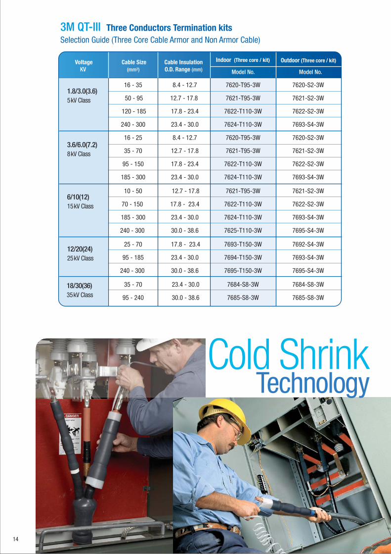
3M QT-III Three Conductors Termination kits Selection Guide (Three Core Cable Armor and Non Armor Cable)
VoltageKV
Cable Size(mm2)
Cable InsulationO.D. Range (mm) Model No. Model No.
16 - 35 8.4 - 12.7 7620-T95-3W 7620-S2-3W
50 - 95 12.7 - 17.8 7621-T95-3W 7621-S2-3W
120 - 185 17.8 - 23.4 7622-T110-3W 7622-S2-3W
240 - 300 23.4 - 30.0 7624-T110-3W 7693-S4-3W
16 - 25 8.4 - 12.7 7620-T95-3W 7620-S2-3W
35 - 70 12.7 - 17.8 7621-T95-3W 7621-S2-3W
95 - 150 17.8 - 23.4 7622-T110-3W 7622-S2-3W
185 - 300 23.4 - 30.0 7624-T110-3W 7693-S4-3W
10 - 50 12.7 - 17.8 7621-T95-3W 7621-S2-3W
70 - 150 17.8 - 23.4 7622-T110-3W 7622-S2-3W
185 - 300 23.4 - 30.0 7624-T110-3W 7693-S4-3W
240 - 300 30.0 - 38.6 7625-T110-3W 7695-S4-3W
25 - 70 17.8 - 23.4 7693-T150-3W 7692-S4-3W
95 - 185 23.4 - 30.0 7694-T150-3W 7693-S4-3W
240 - 300 30.0 - 38.6 7695-T150-3W 7695-S4-3W
35 - 70 23.4 - 30.0 7684-S8-3W 7684-S8-3W
95 - 240 30.0 - 38.6 7685-S8-3W 7685-S8-3W
Indoor (Three core / kit) Outdoor (Three core / kit)
1.8/3.0(3.6)5kV Class
3.6/6.0(7.2)8kV Class
6/10(12)15kV Class
12/20(24)25kV Class
18/30(36)35kV Class
14
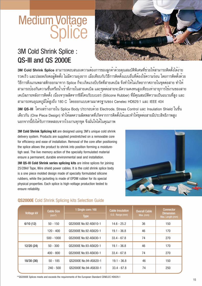
6/10 (12) 50 - 150 QS2000E No.92-AS610-1 14.6 - 25.2 36 150
120 - 400 QS2000E No.92-AS620-1 19.1 - 36.8 46 170
500 - 1000 QS2000E No.92-AS630-1 33.4 - 67.8 74 270
12/20 (24) 50 - 300 QS2000E No.93-AS620-1 19.1 - 36.8 46 170
400 - 800 QS2000E No.93-AS630-1 33.4 - 67.8 74 270
18/30 (36) 50 - 185 QS2000E No.94-AS620-1 19.1 - 36.8 46 150
240 - 500 QS2000E No.94-AS630-1 33.4 - 67.8 74 250
ConnectorDimension
Max. Length (mm)Voltage kV Cable Size
(mm2)
1 Single core / Kit
Type
Cable InsulationO.D. Range (mm)
Overall Cable Max. (mm)
**QS2000E Splices meets and exceeds the requirements of the European Standard CENELEC HD629.1
QS2000E Cold Shrink Splicing kits Selection Guide
3M Cold Shrink Splice : QS-III and QS 2000E 3M Cold Shrink Splice ÊÒÁÒöµÍºÊ¹Í§¤ÇÒÁµéͧ¡ÒâͧÅÙ¡¤éÒ´éǤسÊÁºÑµÔ¾ÔàÈÉ·ÕèªèÇÂãËéÊÒÁÒöµÔ´µÑé§ä´é§èÒ ÃÇ´àÃçÇ áÅлÅÍ´ÀѵèͼÙéµÔ´µÑé§ äÁèÁÕ¤ÇÒÁÂØè§ÂÒ¡ àÁ×èÍà·Õº¡ÑºÇÔ¸Õ¡ÒõԴµÑé§áººÍ×è¹·Õèµéͧãªé¤ÇÒÁÃé͹ â´Â¡ÒõԴµÑ駴éÇÂÇÔ¸Õ¡Òô֧᡹¾ÅÒʵԡÍÍ¡ÁÒ¨Ò¡ Splice ¡ç¨Ðà¡Ô´áçºÕºÃÑ´·ÕèÊÒÂà¤àºÔÅ ¨Ö§·ÓãËéäÁèà¡Ô´ÍÒ¡ÒÈÀÒÂ㹪شµèÍÊÒ ·ÓãËéÊÒÁÒö»éͧ¡Ñ¹¤ÇÒÁª×é¹ËÃ×͹éÓà¢éÒ·ÕèÀÒÂã¹ÊÒÂà¤àºÔÅ áÅЪشµèÍÊÒ¨ÐÁÕ¤ÇÒÁ¤§·¹ÊÙ§à·Õºà·èÒÍÒÂØ¡ÒÃãªé§Ò¹¢Í§ÊÒÂà¤àºÔÅÀÒÂËÅѧ¡ÒõԴµÑé§ à¹×èͧ¨Ò¡¼ÅÔµ¨Ò¡«ÔÅÔ⤹ÃѺºàºÍÃì (Silicone Rubber) ·ÕèÁդسÊÁºÑµÔ¤ÇÒÁà»ç¹©¹Ç¹·ÕèÊÙ§ áÅÐÊÒÁÒö·¹ÍسËÀÙÁÔä´éÊÙ§¶Ö§ 180 C â´ÂÍ͡ẺµÒÁÁҵðҹ¢Í§ Cenelec HD629.1 áÅÐ IEEE 404
3M QS-III â¤Ã§ÊÃéÒ§ÀÒÂã¹ Splice Body »ÃСͺ´éÇ Electrode, Stress Control áÅÐ Insulation Shield 㹪Ôé¹à´ÕÂǡѹ (One Piece Design) ·ÓãËéÅ´¤ÇÒÁ¼Ô´¾ÅÒ´·Õèà¡Ô´¨Ò¡¡ÒõԴµÑé§ä´éáÅзÓãËéªØ´µèÍÊÒÂÁÕ»ÃÐÊÔ·¸ÔÀÒ¾ÊÙ§ ¹Í¡¨Ò¡¹ÕéÂѧä´éÃѺ¡Ò÷´Êͺ¨Ò¡âç§Ò¹·Ø¡ªØ´ ¨Ö§ÁÑè¹ã¨ä´é㹤سÀÒ¾
3M Cold Shrink Splicing kit are designed using 3M's unique cold shrink
delivery system. Products are supplied prestretched on a removable core
for efficiency and ease of installation. Removal of the core after positioning
the splice allows the product to shrink into position forming a moisture-
tigh seal. The live memory action of the specially formulated material
ensure a permanent, durable environmental seal and installation.
3M QS-III Cold Shrink series splicing kits are inline splices for joining
25/28kV Tape, Wire shield power cables. It is the cold shrink splice body
is a one piece molded design made of specially formulated silicone
rubbers, while the jacketing is made of EPDM rubber for its special
physical properties. Each splice is high-voltage production tested to
ensure reliability.
SpliceMedium Voltage
15

25kV Class 70 - 185 QSIII No.5524A 21.3 - 34.5 43 114
12/20 (24) 240 - 500 QSIII No.5525A 27.2 - 43.2 55 165
500 - 800 QSIII No. 5526A 31.5 - 52.6 - -
35kV Class 95 - 240 QSIII No.5535A 27.2 - 43.2 55 16518/30 (36)
ConnectorDimension
Max. Length (mm)Voltage KV
Cable Size(mm2)
1 Single core / Kit
Type
Cable InsulationO.D. Range (mm)
Overall Cable Max. (mm)
**QSIII Splices meet or exceed the requirements of ANSI/IEEE Std.404
**QSIII Splices meet or exceed the requirements of ANSI/IEEE Std.404
16
QS-III Cold Shrink Splicing kits Selection Guide
QSIII Cold Shrink Splicing kits Selection Guide for Three Core Cablewith Armour and Non-Armour Cable
15kV Class 70 - 185 QSIII No.5775A-MT 16.3 - 25.7 76 114
6/10 (12) 240 - 300 QSIII No. 5777A-MT 26.4 - 43.2 114 165
25kV Class 70-185 QS III No.5786A-MT 21.3 - 34.5 90 114
12/20(24) 240-300 QS III No.5787A-MT 27.2 - 43.2 114 165
35kV Class 70-300 QS III No.5797A-MT 27.2 - 43.2 114 165
18/30(36)
ConnectorDimension
Max. Length (mm)Voltage KV
Cable Size(mm2)
3 core / Kit
Type
Cable InsulationO.D. Range (mm)
Overall CableMax. (mm)

17
3M Produce a range of silicone rubber Separable elbow, straight and T connector kits. Each kit contains all the necessary components to install one Separable Connector, including all connection devices.
Elbow ConnectorsSeparable
Minimum skill required: no heat, torch or special tools are neededProvides total safety in case of accidental touchClose positioning between 3 phases and to earthImmediately energisable
Benefits
Material: Silicone rubberProvides a fully screened and submersible systemFast and easy installationAll components included to make the installationMeets European standard specifications: Cenelec HD 629.1 S1 and IEC 60502-4Mechanical connector
Features:
Separable Straight Connectors
Minimum skill required: no heat, torch or special tools are neededProvides total safety in case of accidental touchClose positioning between 3 phases and to earthImmediately energisable
Benefits
Material: Silicone rubberProvides a fully screened and submersible systemFast and easy installationAll components included to make the installationMeets European standard specifications: Cenelec HD 629.1 S1 and IEC 60502-4Mechanical connector
Features:
Separable T-Connectors
Minimum skill required: no heat, torch or special tools are neededProvides total safety in case of accidental touchClose positioning between 3 phases and to earthImmediately energisable
Benefits
Material: Silicone rubberOne-piece design, including a built -in capacitive test pointProvides a fully screened and submersible systemFast and easy installationAll components included to make the installationMeets European standard specifications: Cenelec HD 629.1 S1 and IEC 60502-4Mechanical connector
Features:
pSeparableSeparableConnectors

18
Rated 6/10R d /Separable Connectors
The 93-EE 605-2 kits and the 93-EE 605-4 consist of an elbow type Separable Connector. The assembly is fully screened and has an integrated stress control element. Each kit contains all the necessary components to install one Separable Connector, including all connection devices.
(12)kV
These kits are designed to be installed on wire screened non-armoured polymeric insulated cables for 6/10kV (Um = 12kV) up to 12/20kV (Um = 24kV) – 400A / 630A applications. The Separable Connector establishes the connection between any polymeric insulated cable onto transformers, switchgears, motors or other equipment.
Applications
Elbow Connectors
Kit RefApplication Range
CSA (mm2)Diameter over Primary
Insulation (mm)Connector
Type
93-EE 605-2/-95 25 - 95 17.2 - 25.0 MC 25-95
92-EE 615-2/120 120 Available on request CC 120
92-EE 615-2/150 150 Available on request CC 150
93-EE 605-4/-95 25 - 95 15.0 - 32.6 MC 25-95
93-EE 605-4/-240 95 - 240 15.0 - 32.6 MC 95-240
Elbow Connectors 250A
Elbow Connectors 400A
The 92-EE 600-2 kits consist of a straight type Separable Connector. The assembly is fully screened and has an integrated stress control element. Each kit contains all the necessary components to install one Separable Connector, including all connection devices.
The 92-EE 600-2 kits consist of a straight type Separable Connector. The assembly is fully screened and has an integrated stress control element. Each kit contains all the necessary components to install one Separable Connector, including all connection devices.
Applications
Straight Connectors
The 93-EE 7x5-6 kits consist of a T-type Separable Connector. The assembly is fully screened and has anintegrated stress control element. Each kit contains all the necessary components to install one Plug-In, including all connection devices.
These kits are designed to be installed on wire screened non-armoured polymeric insulated cables for 6/10kV (Um = 12kV) up to 12/20kV (Um = 24kV) – 400A / 630A applications. The Separable Connector establishes the connection between any polymeric insulated cable onto transformers, switchgears, motors or other equipment.
Applications
T-Connectors
Connectors Key
MC = Mechanical ConnectorCC = Compression Connector
Kit RefApplication Range
CSA (mm2)Diameter over Primary
Insulation (mm)
92-EE 600-2/25 25 12.7 - 15.2 CC 25
92-EE 600-2/35 35 13.8 - 16.3 CC 35
92-EE 600-2/50 50 15.0 - 17.5 CC 50
92-EE 600-2/70 70 16.7 - 19.2 CC 70
92-EE 600-2/95 95 18.3 - 20.8 CC 95
92-EE 600-2/120 120 19.8 - 22.8 CC 120
92-EE 600-2/150 150 21.3 - 24.3 CC 150
Straight Connector 250A
ConnectorType
Kit RefApplication Range
CSA (mm2)Diameter over Primary
Insulation (mm)
93-EE 705-6/-95 50 - 95 15.0 - 32.6 MC 25-95
93-EE 705-6/-240 95 - 240 15.0 - 32.6 MC 95-240
92-EE 715-6/300 300 26.3 - 30.4 CC 300
92-EE 715-6/400 400 30.2 - 34.6 CC 400
T Connector 630A
ConnectorType

19
Rated 12/20R d /Separable Connectors
(24)kV
The 93-EE 705-6/x2 kits consist of a T-type Separable Connector. The assembly is fully screened and has an integrated stress control element. Each kit contains all the necessary components to install one Plug-In, including all connection devices.
These kits are designed to be installed on wire screened non-armoured polymeric insulated cables up to 6/10kV (Um = 12kV) up to 12/20kV (Um = 24kV) – 400A / 630A applications. The Separable Connector establishes the connection between any polymeric insulated cable onto transformers, switchgears, motors or other equipment.
Applications
T-Connectors
Kit RefApplication Range
CSA (mm2)Diameter over Primary
Insulation (mm)Connector
Type
93-EE 605-2/-95 25 - 95 17.2 - 25.0 MC 25-95
93-EE 615-2/120 120 24.0 - 27.0 CC 120
93-EE 615-2/150 150 25.5 - 28.5 CC 150
93-EE 605-4/-95 25 - 95 15.0 - 32.6 MC 25-95
93-EE 605-4/-240 95 - 240 15.0 - 32.6 MC 95-240
Elbow Connectors 250A
Elbow Connectors 400A
The 93-EE 605-2 kits and the 93-EE 605-4 consist of an elbow type Separable Connector. The assembly is fully screened and has an integrated stress control element. Each kit contains all the necessary components to install one Separable Connector, including all connection devices.
These kits are designed to be installed on wire screened non-armoured polymeric insulated cables for 6/10kv (Um = 12kV) up to 12/20kV (Um = 24kV) - 400 Applications. The Separable Connector establishes the connection between any polymeric insulated cable onto transformers, switchgears, motors or other equipment.
Applications
Elbow Connectors
The 93-EE 600-2 kits consist of a straight type Separable Connector. The assembly is fully screened and has an integrated stress control element. Each kit contains all the necessary components to install one Separable Connector, including all connection devices.
These kits are designed to be installed on wire screened non-armoured polymeric insulated cables up to 6/10kV (Um = 12kV) up to 12/20kV (Um = 24kV) – 400A / 630A applications. The Separable Connector establishes the connection between any polymeric insulated cable onto transformers, switchgears, motors or other equipment.
Applications
Straight Connectors
Connectors Key
MC = Mechanical ConnectorCC = Compression Connector
Kit RefApplication Range
CSA (mm2)Diameter over Primary
Insulation (mm)
93-EE 600-2/25 25 17.0 - 19.5 CC 25
93-EE 600-2/35 35 18.0 - 20.5 CC 35
93-EE 600-2/50 50 19.2 - 21.7 CC 50
93-EE 600-2/70 70 20.9 - 23.4 CC 70
93-EE 600-2/95 95 22.5 - 25.0 CC 95
93-EE 600-2/120 120 24.0 - 27.0 CC 120
93-EE 600-2/150 150 25.5 - 28.5 CC 150
Straight Connector 250A
ConnectorType
Kit RefApplication Range
CSA (mm2)Diameter over Primary
Insulation (mm)
93-EE 705-6/-95 50 - 95 15.0 - 32.6 MC 25-95
93-EE 705-6/-240 95 - 240 15.0 - 32.6 MC 95-240
92-EE 715-6/300 300 30.2 - 34.6 CC 300
92-EE 715-6/400 400 33.5 - 37.8 CC 400
T Connector 630A
ConnectorType
20
Rated 18/30R d /Separable Connectors
(36)kV
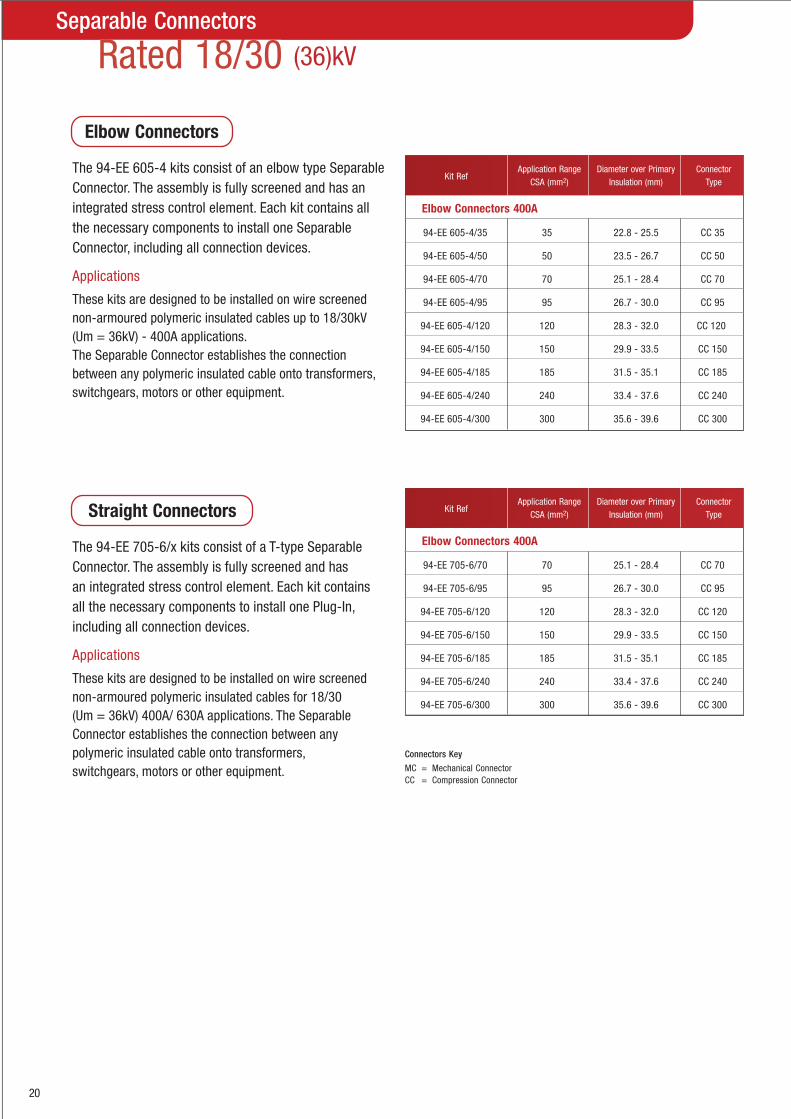
The 94-EE 605-4 kits consist of an elbow type Separable Connector. The assembly is fully screened and has an integrated stress control element. Each kit contains all the necessary components to install one Separable Connector, including all connection devices.
These kits are designed to be installed on wire screened non-armoured polymeric insulated cables up to 18/30kV (Um = 36kV) - 400A applications. The Separable Connector establishes the connection between any polymeric insulated cable onto transformers, switchgears, motors or other equipment.
Applications
Elbow Connectors
The 94-EE 705-6/x kits consist of a T-type Separable Connector. The assembly is fully screened and has an integrated stress control element. Each kit contains all the necessary components to install one Plug-In, including all connection devices.
These kits are designed to be installed on wire screened non-armoured polymeric insulated cables for 18/30 (Um = 36kV) 400A/ 630A applications. The Separable Connector establishes the connection between any polymeric insulated cable onto transformers, switchgears, motors or other equipment.
Applications
Straight Connectors
Kit RefApplication Range
CSA (mm2)Diameter over Primary
Insulation (mm)Connector
Type
94-EE 605-4/35 35 22.8 - 25.5 CC 35
94-EE 605-4/50 50 23.5 - 26.7 CC 50
94-EE 605-4/70 70 25.1 - 28.4 CC 70
94-EE 605-4/95 95 26.7 - 30.0 CC 95
94-EE 605-4/120 120 28.3 - 32.0 CC 120
94-EE 605-4/150 150 29.9 - 33.5 CC 150
94-EE 605-4/185 185 31.5 - 35.1 CC 185
94-EE 605-4/240 240 33.4 - 37.6 CC 240
94-EE 605-4/300 300 35.6 - 39.6 CC 300
Elbow Connectors 400A
Kit RefApplication Range
CSA (mm2)Diameter over Primary
Insulation (mm)Connector
Type
94-EE 705-6/70 70 25.1 - 28.4 CC 70
94-EE 705-6/95 95 26.7 - 30.0 CC 95
94-EE 705-6/120 120 28.3 - 32.0 CC 120
94-EE 705-6/150 150 29.9 - 33.5 CC 150
94-EE 705-6/185 185 31.5 - 35.1 CC 185
94-EE 705-6/240 240 33.4 - 37.6 CC 240
94-EE 705-6/300 300 35.6 - 39.6 CC 300
Elbow Connectors 400A
Connectors Key
MC = Mechanical ConnectorCC = Compression Connector

Lugs Connectors&
21
DimensionsProductNumber
Wire Size(mm2)
StandardWire Size
StudSize
I.D L B W P C
CaseQty
30014 - 6 AWG 10" 0.196" 1.780" 0.750" 0.500" 0.750" 0.375" 50 each (5 mm) (5,0 mm) (45,2 mm) (19,1 mm) (12,7 mm) (19,1 mm) (9,5 mm)
30015 - 6 AWG 1/4" 0.196" 1.780" 0.750" 0.500" 0.750" 0.375" 50 each (6 mm) (5,0 mm) (45,2 mm) (19,1 mm) (12,7 mm) (19,1 mm) (9,5 mm)
30016 - 6 AWG 5/16" 0.196" 1.780" 0.750" 0.435" 0.750" 0.375" 50 each (8 mm) (5,0 mm) (45,2 mm) (19,1 mm) (11,0 mm) (19,1 mm) (9,5 mm)
30018 - 4AWG 10" 0.247" 1.940" 0.750" 0.485" 0.890" 0.375" 50 each (5 mm) (6,3 mm) (49,3 mm) (19,1 mm) (12,3 mm) (22,6 mm) (9,5 mm)
30019 - 4AWG 1/4" 0.247" 1.940" 0.750" 0.485" 0.890" 0.375" 50 each (6 mm) (6,3 mm) (49,3 mm) (19,1 mm) (12,3 mm) (22,6 mm) (9,5 mm)
30021 - 4 AWG 3/8" 0.247" 1.940" 0.750" 0.590" 0.890" 0.375" 50 each (10 mm) (6,3 mm) (49,3 mm) (19,1 mm) (15,1 mm) (22,6 mm) (9,5 mm)
30022 35 2 AWG 1/4" 0.307" 1.970" 0.810" 0.630" 0.890" 0.375" 25 each (6 mm) (7,8 mm) (50,0 mm) (20,7 mm) (15,9 mm) (22,6 mm) (9,5 mm)
30023 35 2AWG 5/16" 0.307" 1.970" 0.810" 0.630" 0.890" 0.375" 25 each (8 mm) (7,8 mm) (50,0 mm) (20,7 mm) (15,9 mm) (22,6 mm) (9,5 mm)
30024 35 2AWG 3/8" 0.307" 1.970" 0.810" 0.630" 0.890" 0.375" 25 each (10 mm) (7,8 mm) (50,0 mm) (20,7 mm) (15,9 mm) (22,6 mm) (9,5 mm)
30027 50 1 AWG 5/16" 0.358" 1.970" 0.810" 0.690" 0.750" 0.375" 10 each (8 mm) (9,1 mm) (50,0 mm) (20,7 mm) (17,4 mm) (19,1 mm) (9,5 mm)
30028 50 1 AWG 3/8" 0.358" 1.970" 0.810" 0.690" 0.750" 0.375" 10 each (10 mm) (9,1 mm) (50,0 mm) (20,7 mm) (17,4 mm) (19,1 mm) (9,5 mm)
30031 50 1/0 AWG 5/16" 0.394" 2.160" 0.810" 0.750" 0.890" 0.375" 10 each (8 mm) (10,0 mm) (54,8 mm) (20,7 mm) (19,0 mm) (22,6 mm) (9,5 mm)
30032 50 1/0 AWG 3/8" 0.394" 2.160" 0.810" 0.750" 0.890" 0.375" 10 each (10 mm) (10,0 mm) (54,8 mm) (20,7 mm) (19,0 mm) (22,6 mm) (9,5 mm)
30036 70 2/0 AWG 3/8" 0.439" 2.370" 0.870" 0.810" 1.110" 0.375" 10 each (10 mm) (11,2 mm) (60,2 mm) (22,2 mm) (20,7 mm) (28,2 mm) (9,5 mm)
30041 95 3/0 AWG 1/2" 0.490" 2.630" 0.940" 0.910" 1.110" 0.531" 10 each (12 mm) (12,4 mm) (66,8 mm) (23,8 mm) (23,0 mm) (28,2 mm) (13,5 mm)
30045 120 4/0 AWG 1/2" 0.548" 2.600" 0.970" 1.000" 1.110" 0.531" 10 each (12 mm) (13,9 mm) (65,9 mm) (24,6 mm) (25,4 mm) (28,2 mm) (13,5 mm)
Specications and Ordering Information for ScotchlokTM 31000 Series Copper Lugs- One Hole, Long-Barrelup to 35 kV
31036 70 2/0 AWG 3/8" 0.439" 2.840" 1.440" 0.812" 0.890" 0.375" 10 each (10 mm) (10 mm) (11,2 mm) (72,2 mm) (36,5 mm (20,6 mm) (22,6 mm)
31041 95 3/0 AWG 1/2" 0.490" 3.130" 1.440" 0.910" 1.110" 0.531" 10 each (12 mm) (12,4 mm) (79,5 mm) (36,5 mm) (23,0 mm) (28,2 mm) (13,5 mm)
31045 120 4/0 AWG 1/2" 0.548" 3.320" 1.560" 1.000" 1.110" 0.531" 10 each (12 mm) (13,9 mm) (84,4mm) (39,7 mm) (25,4 mm) (28,2 mm) (13,5 mm)
31049 150 250 kcmil 1/2" 0.590" 3.380" 1.500" 1.130" 1.110" 0.531" 10 each (12 mm) (15,1 mm) (85,8 mm) (38,0 mm) (28,6 mm) (28,2 mm) (13,5 mm)
31053 - 300 kcmil 1/2" 0.650" 3.780" 1.940" 1.220" 1.110" 0.531" 10 each (150 mm2) (12 mm) (16,5 mm) (96,0 mm) (49,2 mm) (30,9 mm) (28,2 mm) (13,5 mm)
31056 - 350 kcmil 1/2" 0.700" 3.840" 1.940" 1.270" 1.110" 0.531" 10 each (12 mm) (17,8 mm) (97,5 mm) (49,2 mm) (32,3 mm) (28,2 mm) (13,5 mm)
31060 - 400 kcmil 1/2" 0.762" 4.160" 2.000" 1.410" 1.340" 0.650" 10 each (12 mm) (19,3 mm) (105,7 mm) (50,8 mm) (35,8 mm) (34,2 mm) (16,66 mm)
31066 - 500 kcmil 1/2" 0.836" 4.500" 2.190" 1.530" 1.340" 0.660" 10 each (12 mm) (21,2 mm) (114,3 m) (55,6 mm) (38,9 mm) (34,2 mm) (16,8 mm)
31067 - 500 kcmil 5/8" 0.836" 4.500" 2.190" 1.530" 1.340" 0.660" 10 each (16 mm) (21,2 mm) (114,3 mm) (55,6 mm) (38,9 mm) (34,2 mm) (16,8 mm)
31068 - 600 kcmil 1/2" 0.920" 5.120" 2.690" 1.690" 1.750" 0.870" 6 each (12 mm) (23,4 mm) (130,0 mm) (68,2 mm) (42,9 mm) (44,4 mm) (22,2 mm)
Specification and Ordering Information for ScotchlokTM 30000 Series Copper Lugs One Hole up to 35kV
DimensionsProductNumber
Wire Size(mm2)
StandardWire Size
StudSize
I.D L B W P C
CaseQty

31130 50 1/0 AWG 1/2" 0.39" 4.98" 1.38" 0.75" 3.0" 0.63" 1.75" 10 each (12 mm) (9,9 mm) (126,5mm) (31,5mm) (19,0 mm) (76,2 mm) (16,0 mm) (44,4 mm)
31137 70 2/0 AWG 1/2" 0.44" 5.03" 1.50" 0.81" 3.0" 0.63" 1.75" 10 each (12 mm) (11,2 mm) (127,8 mm) (38,1 mm) (20,7 mm) (76,2 mm) (16,0 mm) (44,4mm)
31141 95 3/0 AWG 1/2" 0.49" 5.13" 1.44" 0.91" 3.0" 0.63" 1.75" 10 each
(12 mm) (12,4mm) (130,3mm) (36,5 mm) (23,0 mm) (76,2 mm) (16,0 mm) (44,4 mm)
31145 12 4/0 AWG 1/2" 0.548" 5.160" 1.560" 1.0" 3.0" 0.63" 1.75" 10 each (12 mm) (13,9 mm) (131,0mm) (44,4mm) (39,7 mm) (25,4 mm) (16,0 mm) (15,9 mm)
31149 150 250 kcmil 1/2" 0.595" 5.310" 1.560" 1.130" 3.0" 0.63" 1.75" 10 each (12 mm) (15,1 mm) (134,9 mm) (39,7 mm) (28,6 mm) (76,2 mm) (16,0mm) (44,4mm)
31153 185 300 kcmil 1/2" 0.650" 5.750" 1.940" 1.220" 3.0" 0.63" 1.75" 10 each (150 mm2) (12 mm) (16,5mm) (146,0mm) (49,2 mm) (31,0 mm) (76,2 mm) (16,0 mm) (44,4 mm)
31156 - 350 kcmil 1/2" 0.700" 5.750" 1.940" 1.310" 3.0" 0.63" 1.75" 10 each (12 mm) (17,8 mm) (146,0 mm) (49,2 mm) (33,4 mm) (76,2 mm) (16,0 mm) (44,4 mm)
31160 - 400 kcmil 1/2" 0.762" 6.000" 2.120" 1.410" 3.090" 0.62" 1.75" 10 each (12 mm) (19,35 mm) (152,4 mm) (59,8 mm) (35,8 mm) (78,5 mm) (16,0mm) (44,4 mm)
31166 - 500 kcmil 1/2" 0.836" 6.160" 2.190" 1.530" 3.0" 0.63" 1.75" 10 each (12 mm) (21,2 mm) (156,4 mm) (55,6 mm) (38,9 mm) (76,2 mm) (16,0 mm) (44,4 mm)
31168 - 600 kcmil 1/2" 0.923" 6.720" 2.620" 1.690" 3.120" 0.62" 1.75" 6 each (12 mm) (23,44 mm) (170,6 mm) (66,5 mm) (42,9 mm) (79,2 mm) (16,0 mm) (44,4 mm)
31172 - 750 kcmil 1/2" 1.031" 7.000" 2.810" 1.720" 3.0" 0.63" 1.75" 6 each (12 mm) (26,2 mm) (177,8 mm) (71,5 mm) (43,7 mm) (76,2 mm) (16,0 mm) (44,4 mm)
31178 - 1000 kcmil 1/2" 1.173" 7.280" 2.940" 1.720" 3.0" 0.63" 1.75" 6 each (500 mm2) (12 mm) (29,3 mm) (184,9 mm) (74,6 mm) (43,7 mm) (76,2 mm) (16,0 mm) (44,4 mm)
22
DimensionsProductNumber
Wire Size(mm2)
WireSize
StudSize I.D L B W P C1C
Specifications and Ordering Information for ScotchlokTM 31000 Series Copper Lugs-Two Hole, Long-Barrel up to 35 kV
Min.OrderCase Qty.
10001 - 6 AWG 0.196" (5,0 mm) 0.290" (7,3 mm) 1.750" (44,4 mm) 50 each
10002 - 4 AWG 0.247" (6,2 mm) 0.340" (8,6 mm) 1.750" (44,4 mm) 50 each
10003 - 2 AWG 0.307" (7,8 mm) 0.416" (10,6 mm) 1.880" (47,6 mm) 25 each
10004 - 1 AWG 0.358" (9,1 mm) 0.462" (11,7 mm) 1.880" (47,6 mm) 10 each
10005 50 1/0 AWG 0.394" (10,0 mm) 0.512" (13,0 mm) 1.880" (47,6 mm) 10 each
10006 70 2/0 AWG 0.439" (11,2 mm) 0.560" (14,2 mm) 2.000" (50,8 mm) 10 each
10007 95 3/0 AWG 0.490" (12,4 mm) 0.617" (15,7 mm) 2.130" (54,0 mm) 10 each
10008 120 4/0 AWG 0.548" (13,9 mm) 0.687" (17,4 mm) 2.130" (54,0 mm) 10 each
10009 150 250 kcmil 0.595" (15,1 mm) 0.750" (19,1 mm) 2.250" (57,2 mm) 3 each
10010 - 300 kcmil 0.650" (16,5 mm) 0.813" (20,7 mm) 2.250" (57,2 mm) 3 each
10011 - 350 kcmil 0.700" (17,8 mm) 0.875" (22,2 mm) 2.380" (60,4 mm) 3 each
10014 - 500 kcmil 0.836" (21,2 mm) 1.060" (27,0 mm) 2.880" (73,0 mm) 3 each
10019 - 750 kcmil 1.031" (26,2 mm) 1.299" (33,0 mm) 3.380" (85,8 mm) 3 each
10024 - 1000 kcmil 1.173" (29,8 mm) 1.500" (38,1 mm) 3.880" (98,4 mm) 3 each
Specifications and Ordering Information for ScotchlokTM 10000 Series Copper Connectors-Standard-Barrel up to 35 kV
DimensionsProduct
Number
Wire Size(mm2)
Wire SizeI.D O.D L
Minimum OrderCase Qty.
DimensionsProduct
Number
Wire Size(mm2)
Wire SizeI.D O.D L
Minimum OrderCase Qty.
11006 70 2/0 AWG 0.439" (11,2 mm) 0.560" (14,2 mm) 3.130" (79,4 mm) 10 each
11007 95 3/0 AWG 0.490" (12,4 mm) 0.617" (15,7 mm) 3.130" (79,4 mm) 10 each
11008 120 4/0 AWG 0.548" (13,9 mm) 0.687" (17,4 mm) 3.380" (85,8 mm) 10 each
11009 150 250 kcmil 0.595" (15,1 mm) 0.750" (19,1 mm) 3.380" (85,8 mm) 3 each
11010 185 300 kcmil 0.650" (16,5 mm) 0.813" (20,7 mm) 4.130" (104,8 mm) 3 each
11011 185 350 kcmil 0.700" (17,8 mm) 0.875" (22,2 mm) 4.130" (104,8 mm) 3 each
11014 240 500 kcmil 0.836" (21,2 mm) 1.060" (27,0 mm) 4.630" (117,5 mm) 3 each
11019 400 750 kcmil 1.031" (26,2 mm) 1.299" (33,0 mm) 5.880" (149,2 mm) 3 each
11024 500 1000 kcmil 1.173" (29,8 mm) 1.500" (38,1 mm) 6.130" (155,6 mm) 3 each
Specications and Ordering Information for ScotchlokTM 11000 Series Copper Connectors-Long-Barrel up to 35 kV
Accessories
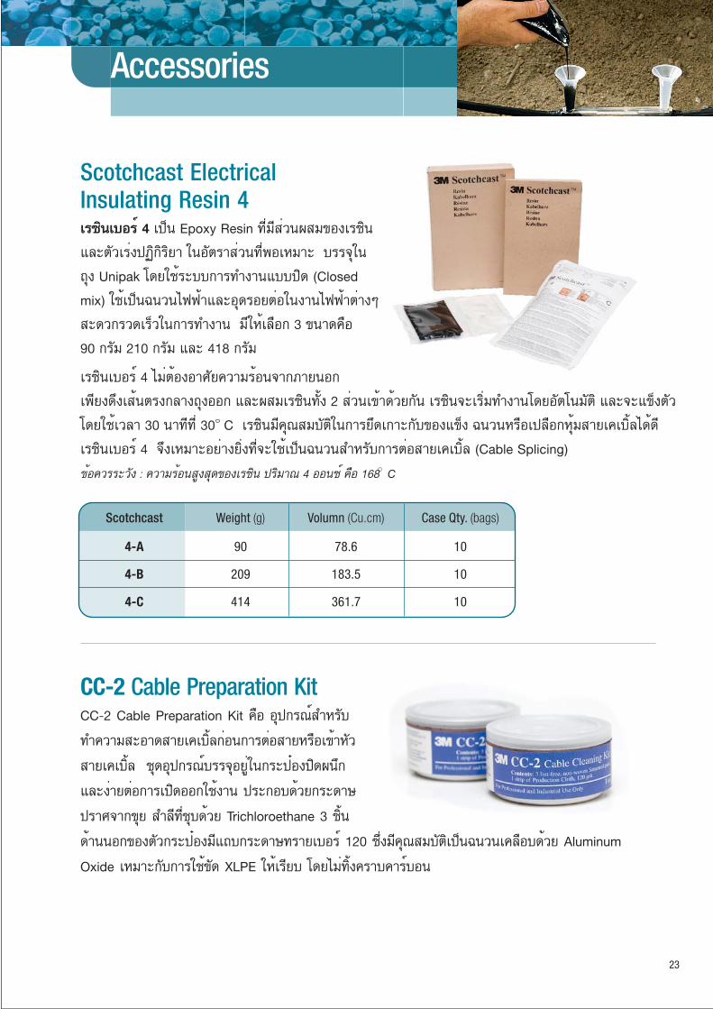
Scotchcast Electrical Insulating Resin 4àëԹàºÍÃì 4 à»ç¹ Epoxy Resin ·ÕèÁÕÊèǹ¼ÊÁ¢Í§àëԹ
áÅеÑÇàÃ觻¯Ô¡ÔÃÔÂÒ ã¹ÍѵÃÒÊèǹ·Õè¾ÍàËÁÒÐ ºÃèØã¹
¶Ø§ Unipak â´ÂãªéÃкº¡Ò÷ӧҹẺ»Ô´ (Closed
mix) ãªéà»ç¹©¹Ç¹ä¿¿éÒáÅÐÍØ´Ã͵èÍ㹧ҹ俿éÒµèÒ§æ
ÊдǡÃÇ´àÃçÇ㹡Ò÷ӧҹ ÁÕãËéàÅ×Í¡ 3 ¢¹Ò´¤×Í
90 ¡ÃÑÁ 210 ¡ÃÑÁ áÅÐ 418 ¡ÃÑÁ
àëԹàºÍÃì 4 äÁèµéͧÍÒÈѤÇÒÁÃé͹¨Ò¡ÀÒ¹͡
à¾Õ§´Ö§àÊ鹵ç¡ÅÒ§¶Ø§ÍÍ¡ áÅмÊÁàëԹ·Ñé§ 2 Êèǹà¢éÒ´éÇ¡ѹ àëԹ¨ÐàÃÔèÁ·Ó§Ò¹â´ÂÍѵâ¹ÁÑµÔ áÅШÐá¢ç§µÑÇ
â´ÂãªéàÇÅÒ 30 ¹Ò·Õ·Õè 30 C àëԹÁդسÊÁºÑµÔ㹡ÒÃÂÖ´à¡ÒСѺ¢Í§á¢ç§ ©¹Ç¹ËÃ×Íà»Å×Í¡ËØéÁÊÒÂà¤àºÔéÅä´é´Õ
àëԹàºÍÃì 4 ¨Ö§àËÁÒÐÍÂèÒ§ÂÔ觷Õè¨Ðãªéà»ç¹©¹Ç¹ÊÓËÃѺ¡ÒõèÍÊÒÂà¤àºÔéÅ (Cable Splicing)
¢éͤÇÃÃÐÇѧ : ¤ÇÒÁÃé͹ÊÙ§ÊØ´¢Í§àëԹ »ÃÔÁÒ³ 4 Í͹«ì ¤×Í 168 C
CC-2 Cable Preparation KitCC-2 Cable Preparation Kit ¤×Í ÍØ»¡Ã³ìÊÓËÃѺ
·Ó¤ÇÒÁÊÐÍÒ´ÊÒÂà¤àºÔéÅ¡è͹¡ÒõèÍÊÒÂËÃ×Íà¢éÒËÑÇ
ÊÒÂà¤àºÔéÅ ªØ´ÍØ»¡Ã³ìºÃèØÍÂÙè㹡Ãлëͧ»Ô´¼¹Ö¡
áÅЧèÒµèÍ¡ÒÃà»Ô´ÍÍ¡ãªé§Ò¹ »ÃСͺ éÇ¡ÃдÒÉ
»ÃÒȨҡ¢Ø ÊÓÅÕ·ÕèªØº´éÇ Trichloroethane 3 ªÔé¹
´éÒ¹¹Í¡¢Í§µÑÇ¡ÃлëͧÁÕᶺ¡ÃдÒÉ·ÃÒÂàºÍÃì 120 «Öè§ÁդسÊÁºÑµÔà»ç¹©¹Ç¹à¤Å×ͺ´éÇ Aluminum
Oxide àËÁÒСѺ¡ÒÃãªé¢Ñ´ XLPE ãËéàÃÕº â´ÂäÁè·Ô駤ÃÒº¤ÒÃìºÍ¹
23
Scotchcast Weight (g) Volumn (Cu.cm) Case Qty. (bags)
4-A 90 78.6 10
4-B 209 183.5 10
4-C 414 361.7 10

3M Ground Strap Assembly Kit GS Series is design for grounding tape-Shielded power cables upto 35kV, Check that cable conductor size match
the ground strap assembly shown in the ordering table below.
Ground Strap Assembly GS Series selection guide
3M Constant Force Springs
5/8 KV 10-50 mm2 70-300 mm2 400-1000 mm2
15 KV 10-35 mm2 50-240 mm2 150-400 mm2
25 KV - 35-185 mm2 120 -500mm2
35 KV - 35-150 mm2 70-300 mm2
ConductorSize
Product Number
GS-1 GS-2 GS-3
12.7 - 19 20.3 - 38.1 25.4 - 56.0 38.1 - 76.2 45.7 - 101.6
Product Number
CFS #1(CFS-0.47/0.78)
CFS#3(CFS-0.80/1.5)
CFS#4(CFS-1.00/2.20)
CFS#5(CFS-1.5/3.0)
CFS#6(CFS-1.8/4.0)
ApplicationRange (mm)
24
25 is a tinned copper braid used for grounding. It has a current-carying capacity of 6 AWG wire (or 13.3 mm2). It is conformable due to its woven construction of 240 strands of 30 AWG tinned copper wires. Use to ground shielded splices and terminations
3M Electrical Grounding Braid : ScotchTM 25
Product Size
ScotchTM 25 1/2" x15' (13mm x 4.6m) 1 roll / box
Inner Unit Pack
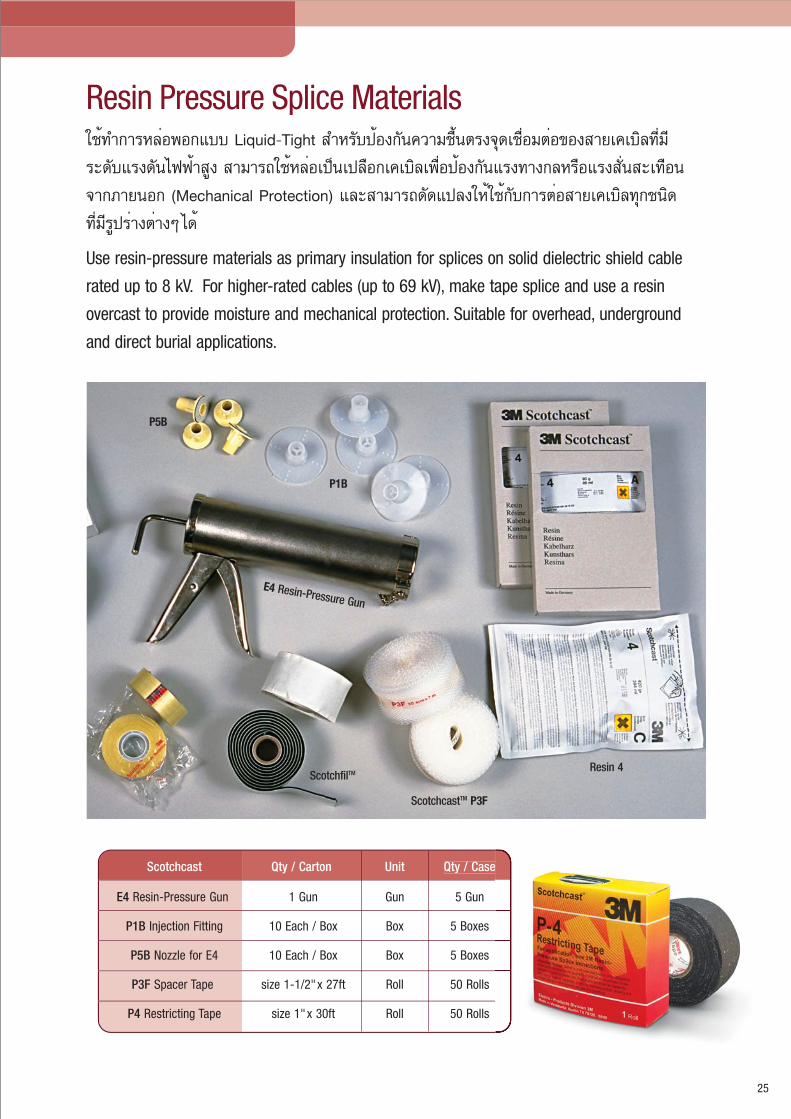
Resin Pressure Splice Materials
25
Use resin-pressure materials as primary insulation for splices on solid dielectric shield cable
rated up to 8 kV. For higher-rated cables (up to 69 kV), make tape splice and use a resin
overcast to provide moisture and mechanical protection. Suitable for overhead, underground
and direct burial applications.
ãªé·Ó¡ÒÃËÅè;͡Ẻ Liquid-Tight ÊÓËÃѺ»éͧ¡Ñ¹¤ÇÒÁª×鹵ç¨Ø´àª×èÍÁµèͧ͢ÊÒÂà¤àºÔÅ·ÕèÁÕ
ÃдѺáç´Ñ¹ä¿¿éÒÊÙ§ ÊÒÁÒöãªéËÅèÍà»ç¹à»Å×Í¡à¤àºÔÅà¾×èÍ»éͧ¡Ñ¹áç·Ò§¡ÅËÃ×ÍáçÊÑè¹ÊÐà·×͹
¨Ò¡ÀÒ¹͡ (Mechanical Protection) áÅÐÊÒÁÒö´Ñ´á»Å§ãËéãªé¡Ñº¡ÒõèÍÊÒÂà¤àºÔÅ·Ø¡ª¹Ô´
·ÕèÁÕÃÙ»ÃèÒ§µèÒ§æ ä´é
Scotchcast Qty / Carton Unit Qty / Case
E4 Resin-Pressure Gun 1 Gun Gun 5 Gun
P1B Injection Fitting 10 Each / Box Box 5 Boxes
P5B Nozzle for E4 10 Each / Box Box 5 Boxes
P3F Spacer Tape size 1-1/2"x 27ft Roll 50 Rolls
P4 Restricting Tape size 1"x 30ft Roll 50 Rolls
Resin 4
E4 Resin-Pressure Gun
P1B
P5B
ScotchfilTM
ScotchcastTM P3F
26
25
12
1
2
3
4
5
7
9
23
3“
1“
1“
A C
B
E
1“16
1“
4
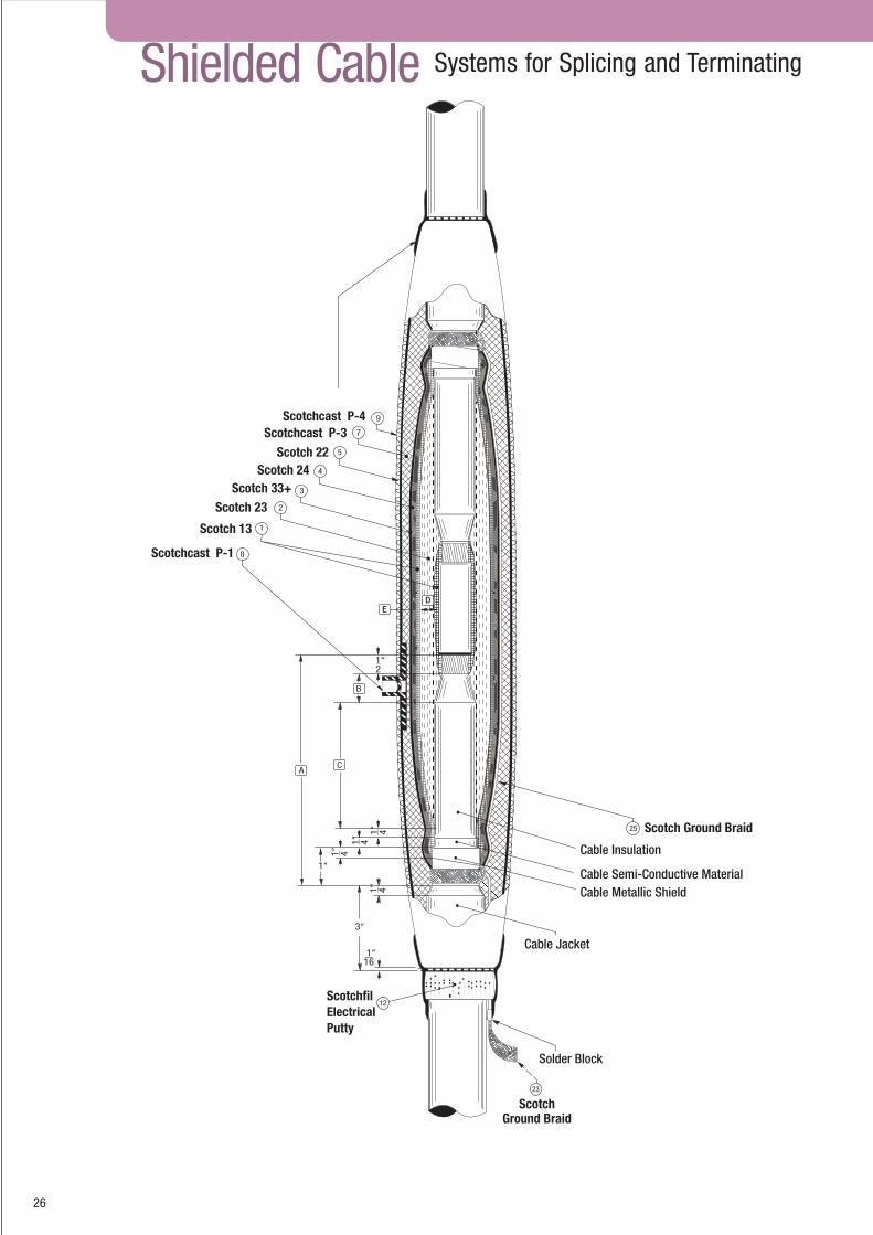
ScotchfilElectricalPutty
ScotchGround Braid
Solder Block
Cable Jacket
Cable Metallic Shield
Cable Semi-Conductive Material
Cable Insulation
Scotch Ground Braid
Scotchcast P-1
Scotchcast P-3Scotchcast P-4
Scotch 13
Scotch 23Scotch 33+
Scotch 24Scotch 22
D
Shielded Cable Systems for Splicing and Terminating
8
1“
4
1“
4
1“
4
2

Material Requirements
A = 9-1/2B = 1-1/2C = 6D = 1/2E = 1/4
13 23 24 33+ P-3 4-C 4-B 22W P-4 S/FIL P-5 P-1 E-4A CC2
1 0.75 2.75 1.50 0.50 2.25 1.00 1.00 0.50 2.25 6" 2.00 1.00 1.00 1.00
1/0 " 3.00 " " 2.50 " " " " " " " " " 2/0 1.00 3.25 " " " " " " 2.50 " " " " " 3/0 " " 1.75 " " 2.00 0.0 " " " " " " " 4/0 " 3.50 " " 2.75 " " " " " " " " " 250 " 3.75 " " " " " " 2.75 " " " " " 300 " 4.00 " " 3.00 " " " " " " " " " 400 1.25 4.50 2.00 " 3.25 " " " 3.00 " " " " " 500 " 5.00 2.25 " " " 1.00 " " " 3.00 " " " 600 " 5.75 " 0.75 3.50 " " 0.75 3.25 " " " " " 750 1.50 6.25 2.50 " 3.75 " " " 2.50 " " " " "1000 1.75 7.25 2.75 " 4.25 3.00 0.0 " 3.75 " " " " "1500 2.00 9.00 3.00 " 3.50 " " " 4.00 " " " " "2000 2.25 10.75 3.50 1.00 5.50 " 1.00 1.00 4.50 " 4.00 " " "2500 2.50 11.75 3.75 " 5.75 4.00 0.0 " 4.75 " " " " "
100%133%
25KV
27
Material Requirements
A = 6B = 3/4C = 3-1/4D = 3/8E = 1/4
13 23 24 33+ P-3 4-C 4-B 22W P-4 S/FIL P-5 P-1 E-4A CC2
2 0.50 1.25 0.75 0.25 1.50 1.00 0.0 0.25 1.50 6" 1.00 1.00 1.00 1.00
1 " " " " " " " " " " " " " " 1/0 " 1.50 1.00 " " " " " " " " " " " 2/0 " " " " 1.75 " " " 1.75 " " " " " 3/0 " 1.75 " " 2.00 " " " " " " " " " 4/0 " " " " " " " " " " " " " " 250 0.75 " " " 2.00 " " " " " " " " " 300 " 2.00 " " " " " 0.50 " " " " " " 400 " 2.25 1.25 0.50 2.25 " " " 2.00 " " " " " 500 " 2.50 " " " " " " 2.25 " " " " " 600 1.00 3.00 1.50 " 2.50 " " " " " " " " " 750 " 3.25 " " 2.75 2.00 0.0 " 2.50 " " " " "1000 1.25 3.75 1.75 " 3.00 " " " 2.75 " " " " "1500 1.50 4.75 2.00 " 3.50 " 1.00 " 3.00 " 3.00 " " "2000 1.75 5.75 2.25 " 4.00 " " " 3.25 " 3.00 " " "2500 " 6.50 2.50 " 4.25 3.00 0.0 " 3.50 " " " " "
100%133%
15kV
Material Requirements
13 23 24 33+ P-3 4-C 4-B 22W P-4 S/FIL P-5 P-1 E-4A CC2
6 0.50 0.75 0.75 0.25 1.25 1.00 0.0 0.25 1.25 6" 1.00 1.00 1.00 1.00
4 " " " " " " " " " " " " " " 2 " 1.00 " " " " " " " " " " " " 1 " " " " " " " " " " " " " " 1/0 " " " " 1.50 " " " 1.50 " " " " " 2/0 " 1.25 " " " " " " " " " " " " 3/0 " " " " " " " " " " " " " " 4/0 " " " " " " " " " " " " " " 250 " 1.50 1.00 " 1.75 " " " 1.75 " " " " " 300 " " " " " " " 0.50 " " " " " " 400 0.75 1.75 " " 2.00 " 1.00 " " " 2.00 " " " 500 " 2.00 1.25 " " " " " 2.00 " " " " " 600 " 2.25 " 0.50 2.25 " " " " " " " " " 750 1.00 2.50 " " 2.50 " " " 2.25 " " " " "1000 " 3.00 1.50 " 2.75 2.00 0.0 " 2.50 " " " " "1500 1.25 4.00 1.75 " 3.25 " " " 2.75 " " " " "2000 1.50 4.75 2.00 " 3.25 " " " 3.00 " 3.00 " " "2500 1.75 5.25 2.25 0.75 4.00 " " 0.75 3.25 " " " " "
A = 5-1/2
B = 3/4
C = 2-3/4
D = 5/16
E = 1/4
100%133%
8kV
Cable Voltage& Insulation
Level (s)
Material Requirements
A = 4-3/4B = 3/4C = 2D = 1/4E = 1/4
ConductorSize
AWG or MCM 13 23 24 33+ P-3 4-C 4-B 22W P-4 S/FIL P-5 P-1 E-4A CC2
8 0.25 0.50 0.50 0.25 1.00 1.00 0.0 0.25 1.00 6" 1.00 1.00 1.00 1.00
6 " " " " " " " " " " " " " " 4 " " " " " " " " " " " " " " 2 " 0.75 " " " " " " 1.25 " " " " " 1 0.50 " " " " " " " " " " " " " 1/0 " " 0.75 " 1.25 " " " " " " " " " 2/0 " " " " " " " " " " " " " " 3/0 " 1.00 " " " " " " " " " " " " 4/0 " " " " " " " " 1.50 " " " " " 250 " " " " 1.50 " " " " " " " " " 300 " " " " " " " " " " " " " " 400 " 1.25 " " 1.75 " " " " " " " " " 500 0.75 1.50 1.00 " " " 1.00 0.50 1.75 " 2.00 " " " 600 " 1.75 " " 2.00 " " " " " " " " " 750 " 2.00 1.25 " " " " " 2.00 " " " " "1000 1.00 2.25 " 0.50 2.50 " " " 2.25 " " " " "1500 1.25 3.00 1.50 " 2.75 2.00 0.0 " 2.50 " " " " "2000 1.50 3.50 1.75 " 3.25 " " " 2.75 " " " " "2500 " 4.00 2.00 " 3.50 " 1.00 " 3.00 " 3.00 " " "
100%133%
5kV
Note* Scotch No.22 Tape replace for Scotch 33W. CC2 Cable Cleaner replace for A2.

ScotchTM 1602 Êà»ÃÂìà¤Å×ͺà¾×èÍà»ç¹©¹Ç¹ (Insulating Sealer)
ãªéÊÓËÃѺ»¡»éͧ¾×é¹¼ÔǨҡ¤ÇÒÁª×é¹ ÊÀÒ¾ÍÒ¡ÒÈ ¡ÒáѴ¡Ãè͹ ¹éÓÁѹ ¡Ã´ áÅдèÒ§ àËÁÒÐÊÓËÃѺ©Õ´à¤Å×ͺº¹©¹Ç¹¢Í§ÊÒÂä¿ ¨Ø´µèͧ͢ÊÒÂà¤àºÔéÅà¾×èÍà»ç¹©¹Ç¹ ËÃ×Íà¾×èÍ«èÍÁá«Á©¹Ç¹¢Í§ÁÍàµÍÃì áÅÐâ¤Ã§¢Í§ÁÍàµÍÃì
¢¹Ò´ 340g
3M Aerosols
ÊÔ¹¤éÒÊà»ÃÂìà¾×èͧҹ俿éÒ
ÁÕÊèǹ¼ÊÁ¢Í§Êѧ¡ÐÊÕºÃÔÊØ·¸Ôì 97% ãªéÊÓËÃѺà¤Å×ͺà¾×èÍÂѺÂÑ駡ÒÃà¡Ô´Ê¹ÔÁ¢Í§à¤Ã×èͧ¡Óà¹Ô´ä¿¿éÒÍØ»¡Ã³ìã¹ÃкºÊÒÂÊè§áÅШÓ˹èÒ àÊÒä¿¿éÒ ËÁéÍá»Å§ ÃÇÁ·Ñ駾×é¹¼ÔǢͧÇÑÊ´Ø·Õèà»ç¹âÅËÐáÅÐÊѧ¡ÐÊÕà¤Å×ͺ (Galvanized) ·Ø¡ª¹Ô´ ¡ÒÃà¤Å×ͺ´éÇ 16-501 ÁդسÊÁºÑµÔà·Õºà·èҡѺ¡Òêغ éÇ Hot Dipped Galvanized
3M 16-501 «Ô§¤ìÊà»ÃÂì (Zinc Spray)
Performance, Economy and
Convenience28
ËÁÒÂà赯 : ÊÔ¹¤éÒã¹ËÁÇ´¹Õéµéͧãªé§Ò¹ã¹¢³Ð·Õèà¤Ã×èͧ¨Ñ¡ÃäÁèÁÕ¡ÒèèÒÂä¿
3M 16-102 ¹éÓÂÒ·Ó¤ÇÒÁÊÐÍҴ˹éÒÊÑÁ¼ÑÊ (Quick Drying Contact Cleaner)
àËÁÒÐÊÓËÃѺ·Ó¤ÇÒÁÊÐÍÒ´ªÔé¹Êèǹ ÍÔàŤ·Ã͹ԤÊìµèÒ§æ ËÃ×Í˹éÒÊÑÁ¼ÑÊ ·Ò§ä¿¿éÒ ¨Ø´µèÍÊÒ áÅÐÍØ»¡Ã³ìä¿¿éÒ àªè¹ »ÅÑê¡ ÊÇÔµ«ì á¨ç¤ àºÃ¡à¡ÍÃì ÃÕàÅÂì 㹪ش¤Çº¤ØÁÁÍàµÍÃì ÃÐàËÂä´éàÃçÇâ´Â äÁè·Ô駤ÃÒº áÅÐäÁèÁÕÊèǹ¼ÊÁ¢Í§ÊÒà CFC «Öè§à»ç¹µÑÇ¡Ò÷ÓÅÒÂÊÀÒ¾áÇ´ÅéÍÁ ¢¹Ò´ 298g
à»ç¹à¨ÅËÅèÍÅ×è¹ÊÓËÃѺ§Ò¹ÅÒ¡ÊÒÂä¿¿éÒ ã¹ºÃÔàdz·ÕèÁÕ¤ÇÒÁÃé͹ÊÙ§ä´é¶Ö§ 60 C ÊÒÁÒöŴáçàÊÕ´·Ò¹¢³Ð´Ö§ÊÒÂä¿¿éÒ à¾×èÍ»éͧ¡Ñ¹¡ÒêÓÃØ´¢Í§ÊÒÂä¿¿éÒä´éà»ç¹ÍÂèÒ§´ÕÁÕ¢¹Ò´ 1 áÅÐ 5 á¡ÅÅ͹
3M WLX-1 and WLX-5 Wire Pulling Lubricant Wax
ãªé·Òà¾×èͪèÇ»éͧ¡Ñ¹¨Ø´µèÍ·Õè¾Ñ¹´éÇÂà·»¾ÕÇÕ«Õ ¨Ò¡¹éÓÁѹ ¤ÇÒÁª×é¹áÅСÒáѴ¡Ãè͹¨Ò¡ÊÀÒ¾áÇ´ÅéÍÁºÃèØ㹡Ãлëͧ¾ÃéÍÁá»Ã§ à¾×èͤÇÒÁÊдǡ㹡ÒÃãªé§Ò¹
3M ScotchkoteTM Electrical Coating

20
18
16
14
.001
.75
.0015
.002
1.0
12
10
9
1.5
2.5
4
8
7
6
5
4
3
2
1
1/0
2/0
3/0
4/0
250
300
350
400
500
600700750800
1000
1250
1500
2000
6
10
25
35
50
16
.003
.0045
.007
.01
.0145
.0225
.03
.04
.06
70
95
120
150
185
240
300
400
500
625
800
1000
.075
.12
.15
.2
.25
.3
.4
.5
.75
.85
1.00
1.25
1.50
.6
.1
A.W.G.SQ.IN.METRICmm2
Wire SizeConversion Chart

AW20
11-0
1183
á¼¹¡¼ÅÔμÀѳ±�ä¿¿éÒºÃÔÉÑ· 3àÍçÁ »ÃÐà·Èä·Â ¨Ó¡Ñ´ªÑé¹ 12 ÍÒ¤ÒÃàÊÃÔÁÁÔμ÷ÒÇàÇÍÃ�159 ¶¹¹ÍâÈ¡Á¹μÃÕ á¢Ç§¤ÅͧàμÂà˹×Í à¢μÇѲ¹Ò ¡ÃØ§à·¾Ï 10110â·ÃÈѾ·� 0-2260-8577 â·ÃÊÒà 0-2261-7535www.3M.com/th www.facebook.com/3MTHAILAND