3ma series - hydraulic industrial services, inc. hannifin corporation pneumatic division richland,...
TRANSCRIPT
Parker Hannifin CorporationPneumatic DivisionRichland, Michiganwww.parker.com/pneumatics
B6
Catalog PDN1000-3US
Parker Pneumatic
B
Tie Rod Cylinders Actuator Products
3MA
Series4M
A/4ML
Series3M
AJ/4MAJ
Series4M
NR
SeriesP1D
Series
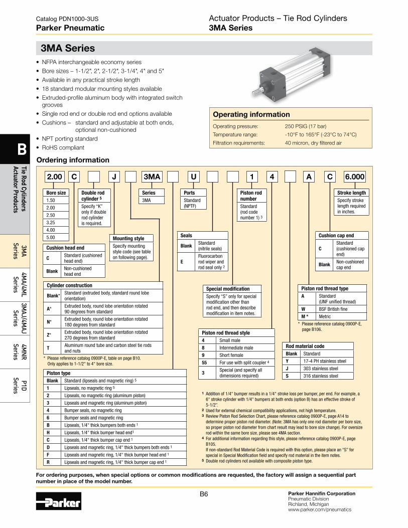
3MA Series
Actuator Products – Tie Rod Cylinders3MA Series
Operating information
Operating pressure: 250 PSIG (17 bar)
Temperature range: -10°F to 165°F (-23°C to 74°C)
Filtration requirements: 40 micron, dry filtered air
• NFPA interchangeable economy series
• Bore sizes – 1-1/2", 2", 2-1/2", 3-1/4", 4" and 5"
• Available in any practical stroke length
• 18 standard modular mounting styles available
• Extruded-profile aluminum body with integrated switch
grooves
• Single rod end or double rod end options available
• Cushions – standard and adjustable at both ends,
optional non-cushioned
• NPT porting standard
• RoHS compliant
Ordering information
C2.00 J U 1 4 A C 6.000
Cylinder construction
Blank* Standard (extruded body, standard round lobe orientation)
A* Extruded body, round lobe orientation rotated 90 degrees from standard
N* Extruded body, round lobe orientation rotated 180 degrees from standard
Z* Extruded body, round lobe orientation rotated 270 degrees from standard
TAluminum round tube and carbon steel tie rods and nuts
* Please reference catalog 0900P-E, table on page B10. Only applies to 1-1/2" to 4" bore size.
Piston type
Blank Standard (lipseals and magnetic ring) 5
1 Lipseals, no magnetic ring 5
2 Lipseals, no magnetic ring (aluminum piston)
3 Lipseals and magnetic ring (aluminum piston)
4 Bumper seals, no magnetic ring
6 Bumper seals and magnetic ring
B Lipseals, 1/4" thick bumpers both ends 1
H Lipseals, 1/4" thick bumper head end1
C Lipseals, 1/4" thick bumper cap end 1
D Lipseals and magnetic ring, 1/4" thick bumpers both ends 1
F Lipseals and magnetic ring, 1/4" thick bumper head end 1
R Lipseals and magnetic ring, 1/4" thick bumper cap end 1
Bore size
1.50
2.00
2.50
3.25
4.00
5.00
Special modification
Specify “S” only for special modification other than rod end, and then describe modification in item notes.
Stroke length
Specify stroke length required in inches.
Mounting style
Specify mounting style code (see table on following page).
Double rod
cylinder 5
Specify “K” only if double rod cylinder is required.
Piston rod
number
Standard (rod code number 1) 3
Series
3MA
Ports
Standard (NPTF)
Cushion head end
CStandard (cushioned head end)
BlankNon-cushioned head end
Piston rod thread type
A Standard (UNF unified thread)
W BSF British fine
M * Metric
* Please reference catalog 0900P-E, page B106.
Rod material code
Blank Standard
Y 17-4 PH stainless steel
J 303 stainless steel
S 316 stainless steel
Piston rod thread style
4 Small male
8 Intermediate male
9 Short female
55 For use with split coupler 4
3Special (and specify all dimensions required)
Seals
BlankStandard (nitrile seals)
E
Fluorocarbon rod wiper and rod seal only 2
Cushion cap end
C
Standard (cushioned cap end)
BlankNon-cushioned cap end
3MA
1 Addition of 1/4" bumper results in a 1/4" stroke loss per bumper, per end. For example, a 6" stroke cylinder with 1/4" bumpers at both ends (option B) has an effective stroke of 5-1/2".
2 Used for external chemical compatibility applications, not high temperature.3 Review Piston Rod Selection Chart, please reference catalog 0900P-E, page A14 to
determine proper piston rod diameter. (Note: 3MA has only one rod diameter per bore size, so proper piston rod diameter from chart result may lead to bore size change). For oversize rod within the same bore size, please see 4MA section.
4 For additional information regarding this style, please reference catalog 0900P-E, page B105. If non-standard Rod Material Code is required with this option, please place an “S” for special in Special Modification field and specify rod material in the item notes.
5 Double rod cylinders not available with composite piston type.
For ordering purposes, when special options or common modifications are requested, the factory will assign a sequential part
number in place of the model number.
Parker Hannifin CorporationPneumatic DivisionRichland, Michiganwww.parker.com/pneumatics
B7
Catalog PDN1000-3US
Parker Pneumatic
B
Tie
Rod
Cylin
ders
Ac
tuat
or P
rodu
cts
3MA
Serie
s4M
A/4M
L Se
ries
3MAJ
/4M
AJ
Serie
s4M
NR
Serie
sP1
D Se
ries
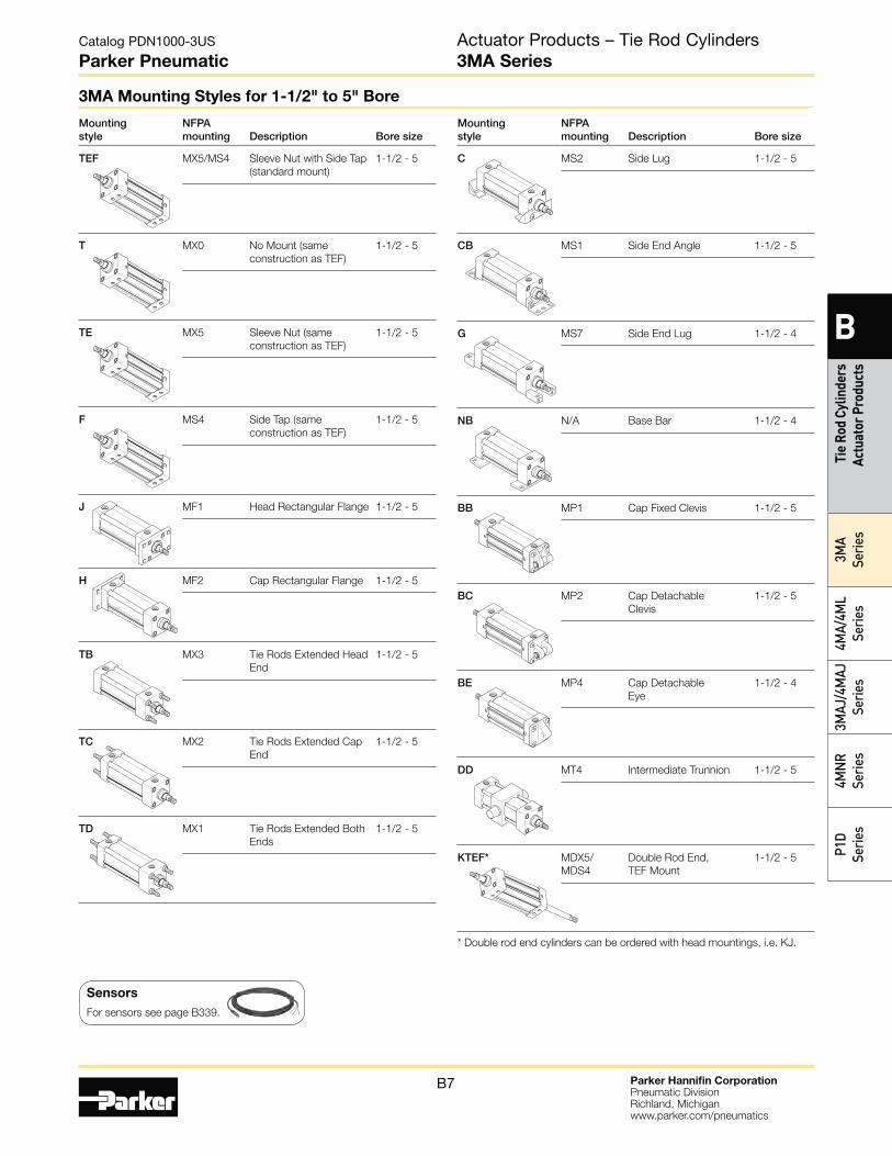
Mounting style
NFPA mounting Description Bore size
C MS2 Side Lug 1-1/2 - 5
CB MS1 Side End Angle 1-1/2 - 5
G MS7 Side End Lug 1-1/2 - 4
NB N/A Base Bar 1-1/2 - 4
BB MP1 Cap Fixed Clevis 1-1/2 - 5
BC MP2 Cap Detachable
Clevis
1-1/2 - 5
BE MP4 Cap Detachable
Eye
1-1/2 - 4
DD MT4 Intermediate Trunnion 1-1/2 - 5
KTEF* MDX5/
MDS4
Double Rod End,
TEF Mount
1-1/2 - 5
* Double rod end cylinders can be ordered with head mountings, i.e. KJ.
Mounting style
NFPA mounting Description Bore size
TEF MX5/MS4 Sleeve Nut with Side Tap
(standard mount)
1-1/2 - 5
T MX0 No Mount (same
construction as TEF)
1-1/2 - 5
TE MX5 Sleeve Nut (same
construction as TEF)
1-1/2 - 5
F MS4 Side Tap (same
construction as TEF)
1-1/2 - 5
J MF1 Head Rectangular Flange 1-1/2 - 5
H MF2 Cap Rectangular Flange 1-1/2 - 5
TB MX3 Tie Rods Extended Head
End
1-1/2 - 5
TC MX2 Tie Rods Extended Cap
End
1-1/2 - 5
TD MX1 Tie Rods Extended Both
Ends
1-1/2 - 5
Actuator Products – Tie Rod Cylinders3MA Series
3MA Mounting Styles for 1-1/2" to 5" Bore
Sensors
For sensors see page B339.
Parker Hannifin CorporationPneumatic DivisionRichland, Michiganwww.parker.com/pneumatics
B8
Catalog PDN1000-3US
Parker Pneumatic
B
Tie Rod Cylinders Actuator Products
3MA
Series4M
A/4ML
Series3M
AJ/4MAJ
Series4M
NR
SeriesP1D
Series
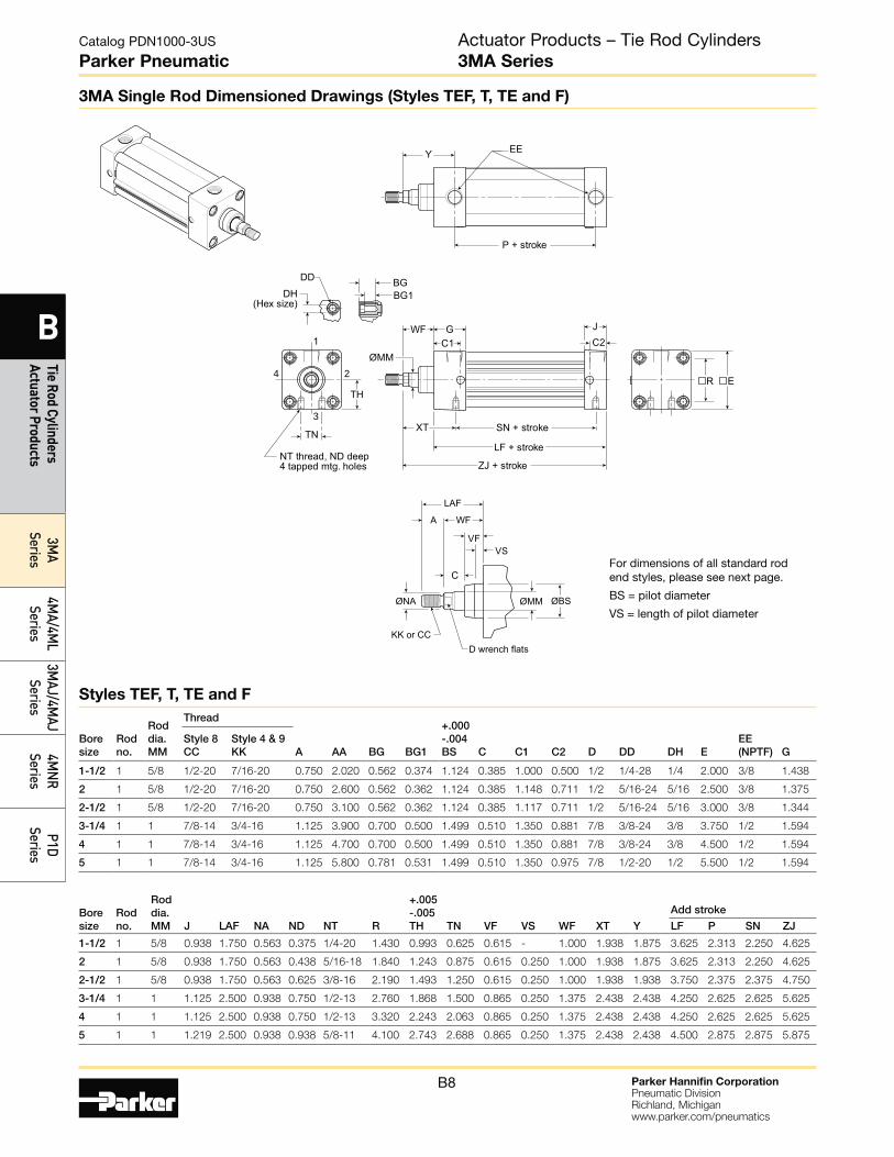
3MA Single Rod Dimensioned Drawings (Styles TEF, T, TE and F)
Styles TEF, T, TE and F
For dimensions of all standard rod end styles, please see next page.
BS = pilot diameter
VS = length of pilot diameter
Boresize
Rodno.
Roddia.MM
Thread
A AA BG BG1
+.000-.004BS C C1 C2 D DD DH E
EE (NPTF) G
Style 8CC
Style 4 & 9KK
1-1/2 1 5/8 1/2-20 7/16-20 0.750 2.020 0.562 0.374 1.124 0.385 1.000 0.500 1/2 1/4-28 1/4 2.000 3/8 1.438
2 1 5/8 1/2-20 7/16-20 0.750 2.600 0.562 0.362 1.124 0.385 1.148 0.711 1/2 5/16-24 5/16 2.500 3/8 1.375
2-1/2 1 5/8 1/2-20 7/16-20 0.750 3.100 0.562 0.362 1.124 0.385 1.117 0.711 1/2 5/16-24 5/16 3.000 3/8 1.344
3-1/4 1 1 7/8-14 3/4-16 1.125 3.900 0.700 0.500 1.499 0.510 1.350 0.881 7/8 3/8-24 3/8 3.750 1/2 1.594
4 1 1 7/8-14 3/4-16 1.125 4.700 0.700 0.500 1.499 0.510 1.350 0.881 7/8 3/8-24 3/8 4.500 1/2 1.594
5 1 1 7/8-14 3/4-16 1.125 5.800 0.781 0.531 1.499 0.510 1.350 0.975 7/8 1/2-20 1/2 5.500 1/2 1.594
Boresize
Rodno.
Roddia.MM J LAF NA ND NT R
+.005-.005TH TN VF VS WF XT
Y
Add stroke
LF P SN ZJ
1-1/2 1 5/8 0.938 1.750 0.563 0.375 1/4-20 1.430 0.993 0.625 0.615 - 1.000 1.938 1.875 3.625 2.313 2.250 4.625
2 1 5/8 0.938 1.750 0.563 0.438 5/16-18 1.840 1.243 0.875 0.615 0.250 1.000 1.938 1.875 3.625 2.313 2.250 4.625
2-1/2 1 5/8 0.938 1.750 0.563 0.625 3/8-16 2.190 1.493 1.250 0.615 0.250 1.000 1.938 1.938 3.750 2.375 2.375 4.750
3-1/4 1 1 1.125 2.500 0.938 0.750 1/2-13 2.760 1.868 1.500 0.865 0.250 1.375 2.438 2.438 4.250 2.625 2.625 5.625
4 1 1 1.125 2.500 0.938 0.750 1/2-13 3.320 2.243 2.063 0.865 0.250 1.375 2.438 2.438 4.250 2.625 2.625 5.625
5 1 1 1.219 2.500 0.938 0.938 5/8-11 4.100 2.743 2.688 0.865 0.250 1.375 2.438 2.438 4.500 2.875 2.875 5.875
R E
EEY
ØMM
XT
WF G J
C1 C2
DH(Hex size)
DD
1
BG1BG
SN + stroke
LF + stroke
ZJ + stroke
P + stroke
TN
NT thread, ND deep4 tapped mtg. holes
TH
KK or CCD wrench flats
ØMM
WF
VF
C
LAF
A
VS
24
3
ØBSØNA
Actuator Products – Tie Rod Cylinders3MA Series
Parker Hannifin CorporationPneumatic DivisionRichland, Michiganwww.parker.com/pneumatics
B9
Catalog PDN1000-3US
Parker Pneumatic
B
Tie
Rod
Cylin
ders
Ac
tuat
or P
rodu
cts
3MA
Serie
s4M
A/4M
L Se
ries
3MAJ
/4M
AJ
Serie
s4M
NR
Serie
sP1
D Se
ries
KK
ØNA
D wrench flats
WFVF
C
LAFA
Groove has 1/16"internal radii atcorners
VS
KK
ØNA
D wrench flats
ØBS ØBS
WFVF
C
VS
A
CCD wrench flats
WFVF
C
LAFA
VS
VF
VSØ
Ø
ØBSØ ØBSØ
1/16
Ø A
WGAD
AØAF
ØNA
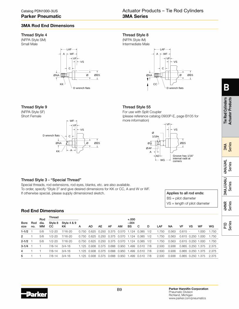
3MA Rod End Dimensions
Thread Style 4(NFPA Style SM)
Small Male
Thread Style 8(NFPA Style IM)
Intermediate Male
Thread Style 9(NFPA Style SF)
Short Female
Thread Style 55For use with Split Coupler
(please reference catalog 0900P-E, page B105 for
more information)
Thread Style 3 - “Special Thread”Special threads, rod extensions, rod eyes, blanks, etc. are also available.
To order, specify “Style 3” and give desired dimensions for KK or CC, A and W or WF.
If otherwise special, please supply dimensioned sketch. Applies to all rod ends:BS = pilot diameter
VS = length of pilot diameter
Boresize
Rodno.
Roddia.MM
Thread
A AD AE AF AM
+.000-.004BS C D LAF NA VF VS WF WG
Style 8CC
Style 4 & 9KK
1-1/2 1 5/8 1/2-20 7/16-20 0.750 0.625 0.250 0.375 0.570 1.124 0.385 1/2 1.750 0.563 0.615 - 1.000 1.750
2 1 5/8 1/2-20 7/16-20 0.750 0.625 0.250 0.375 0.570 1.124 0.385 1/2 1.750 0.563 0.615 0.250 1.000 1.750
2-1/2 1 5/8 1/2-20 7/16-20 0.750 0.625 0.250 0.375 0.570 1.124 0.385 1/2 1.750 0.563 0.615 0.250 1.000 1.750
3-1/4 1 1 7/8-14 3/4-16 1.125 0.938 0.375 0.688 0.950 1.499 0.510 7/8 2.500 0.938 0.865 0.250 1.375 2.375
4 1 1 7/8-14 3/4-16 1.125 0.938 0.375 0.688 0.950 1.499 0.510 7/8 2.500 0.938 0.865 0.250 1.375 2.375
5 1 1 7/8-14 3/4-16 1.125 0.938 0.375 0.688 0.950 1.499 0.510 7/8 2.500 0.938 0.865 0.250 1.375 2.375
Rod End Dimensions
Actuator Products – Tie Rod Cylinders3MA Series
Parker Hannifin CorporationPneumatic DivisionRichland, Michiganwww.parker.com/pneumatics
B10
Catalog PDN1000-3US
Parker Pneumatic
B
Tie Rod Cylinders Actuator Products
3MA
Series4M
A/4ML
Series3M
AJ/4MAJ
Series4M
NR
SeriesP1D
Series
F
1
F
FB oles
F Stro e
1 WLA LB Stro e
F
1
F
FB oles
FF Stro e
1
Stro e
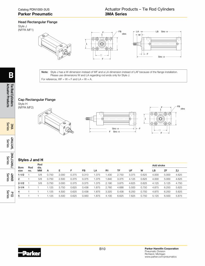
Head Rectangular FlangeStyle J
(NFPA MF1)
Cap Rectangular FlangeStyle H
(NFPA MF2)
Note: Style J has a W dimension instead of WF and a LA dimension instead of LAF because of the flange installation.
Please use dimensions W and LA regarding rod ends only for Style J.
For reference, WF = W + F and LA = W + A.
Boresize
Rodno.
Roddia.MM A E F FB LA R1 TF UF W
Add stroke
LB ZF ZJ
1-1/2 1 5/8 0.750 2.000 0.375 0.313 1.375 1.430 2.750 3.375 0.625 4.000 5.000 4.625
2 1 5/8 0.750 2.500 0.375 0.375 1.375 1.840 3.375 4.125 0.625 4.000 5.000 4.625
2-1/2 1 5/8 0.750 3.000 0.375 0.375 1.375 2.190 3.875 4.625 0.625 4.125 5.125 4.750
3-1/4 1 1 1.125 3.750 0.625 0.438 1.875 2.760 4.688 5.500 0.750 4.875 6.250 5.625
4 1 1 1.125 4.500 0.625 0.438 1.875 3.320 5.438 6.250 0.750 4.875 6.250 5.625
5 1 1 1.125 5.500 0.625 0.563 1.875 4.100 6.625 7.625 0.750 5.125 6.500 5.875
Styles J and H
Actuator Products – Tie Rod Cylinders3MA Series
Parker Hannifin CorporationPneumatic DivisionRichland, Michiganwww.parker.com/pneumatics
B11
Catalog PDN1000-3US
Parker Pneumatic
B
Tie
Rod
Cylin
ders
Ac
tuat
or P
rodu
cts
3MA
Serie
s4M
A/4M
L Se
ries
3MAJ
/4M
AJ
Serie
s4M
NR
Serie
sP1
D Se
ries
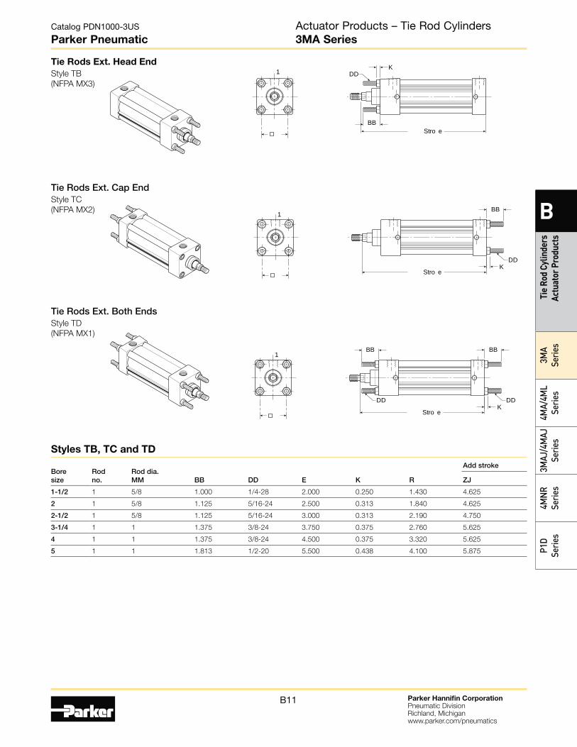
Tie Rods Ext. Head End
Style TB
(NFPA MX3)
1BB
Stro e
DDK
1
BB Stro e
DDK
1BBBB
Stro e
DDDDK
Tie Rods Ext. Both EndsStyle TD
(NFPA MX1)
Tie Rods Ext. Cap EndStyle TC
(NFPA MX2)
Bore size
Rod no.
Rod dia. MM BB DD E K R
Add stroke
ZJ
1-1/2 1 5/8 1.000 1/4-28 2.000 0.250 1.430 4.625
2 1 5/8 1.125 5/16-24 2.500 0.313 1.840 4.625
2-1/2 1 5/8 1.125 5/16-24 3.000 0.313 2.190 4.750
3-1/4 1 1 1.375 3/8-24 3.750 0.375 2.760 5.625
4 1 1 1.375 3/8-24 4.500 0.375 3.320 5.625
5 1 1 1.813 1/2-20 5.500 0.438 4.100 5.875
Styles TB, TC and TD
Actuator Products – Tie Rod Cylinders3MA Series
Parker Hannifin CorporationPneumatic DivisionRichland, Michiganwww.parker.com/pneumatics
B12
Catalog PDN1000-3US
Parker Pneumatic
B
Tie Rod Cylinders Actuator Products
3MA
Series4M
A/4ML
Series3M
AJ/4MAJ
Series4M
NR
SeriesP1D
Series
A
A
AA
ALF
A
A
AL1
AB6 oles
A Stro eA Stro e
1
SA Stro e
S
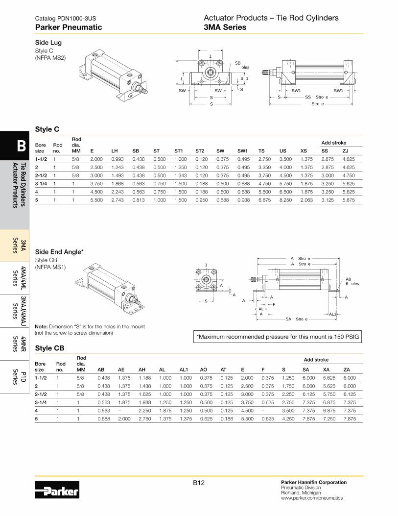
Side End Angle*Style CB
(NFPA MS1)
Note: Dimension “S” is for the holes in the mount
(not the screw to screw dimension)*Maximum recommended pressure for this mount is 150 PSIG
SWSWSS
S 1
S
SB oles
SW1 SW1
L
S
1
Stro eSS Stro e
Side LugStyle C
(NFPA MS2)
Bore size
Rod no.
Rod dia. MM AB AE AH AL AL1 AO AT E F S
Add stroke
SA XA ZA
1-1/2 1 5/8 0.438 1.375 1.188 1.000 1.000 0.375 0.125 2.000 0.375 1.250 6.000 5.625 6.000
2 1 5/8 0.438 1.375 1.438 1.000 1.000 0.375 0.125 2.500 0.375 1.750 6.000 5.625 6.000
2-1/2 1 5/8 0.438 1.375 1.625 1.000 1.000 0.375 0.125 3.000 0.375 2.250 6.125 5.750 6.125
3-1/4 1 1 0.563 1.875 1.938 1.250 1.250 0.500 0.125 3.750 0.625 2.750 7.375 6.875 7.375
4 1 1 0.563 – 2.250 1.875 1.250 0.500 0.125 4.500 – 3.500 7.375 6.875 7.375
5 1 1 0.688 2.000 2.750 1.375 1.375 0.625 0.188 5.500 0.625 4.250 7.875 7.250 7.875
Bore size
Rod no.
Rod dia. MM E LH SB ST ST1 ST2 SW SW1 TS US XS
Add stroke
SS ZJ
1-1/2 1 5/8 2.000 0.993 0.438 0.500 1.000 0.120 0.375 0.495 2.750 3.500 1.375 2.875 4.625
2 1 5/8 2.500 1.243 0.438 0.500 1.250 0.120 0.375 0.495 3.250 4.000 1.375 2.875 4.625
2-1/2 1 5/8 3.000 1.493 0.438 0.500 1.343 0.120 0.375 0.495 3.750 4.500 1.375 3.000 4.750
3-1/4 1 1 3.750 1.868 0.563 0.750 1.500 0.188 0.500 0.688 4.750 5.750 1.875 3.250 5.625
4 1 1 4.500 2.243 0.563 0.750 1.500 0.188 0.500 0.688 5.500 6.500 1.875 3.250 5.625
5 1 1 5.500 2.743 0.813 1.000 1.500 0.250 0.688 0.938 6.875 8.250 2.063 3.125 5.875
Style C
Style CB
Actuator Products – Tie Rod Cylinders3MA Series
Parker Hannifin CorporationPneumatic DivisionRichland, Michiganwww.parker.com/pneumatics
B13
Catalog PDN1000-3US
Parker Pneumatic
B
Tie
Rod
Cylin
ders
Ac
tuat
or P
rodu
cts
3MA
Serie
s4M
A/4M
L Se
ries
3MAJ
/4M
AJ
Serie
s4M
NR
Serie
sP1
D Se
ries
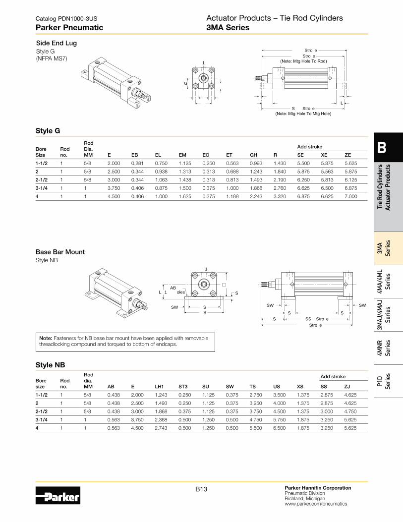
Side End LugStyle G
(NFPA MS7)
G
L
Stro e
1
S Stro e(Note: Mtg Hole To Mtg Hole)
Stro e(Note: Mtg Hole To Rod)
Bore Size
Rod no.
Rod Dia. MM E EB EL EM EO ET GH R
Add stroke
SE XE ZE
1-1/2 1 5/8 2.000 0.281 0.750 1.125 0.250 0.563 0.993 1.430 5.500 5.375 5.625
2 1 5/8 2.500 0.344 0.938 1.313 0.313 0.688 1.243 1.840 5.875 5.563 5.875
2-1/2 1 5/8 3.000 0.344 1.063 1.438 0.313 0.813 1.493 2.190 6.250 5.813 6.125
3-1/4 1 1 3.750 0.406 0.875 1.500 0.375 1.000 1.868 2.760 6.625 6.500 6.875
4 1 1 4.500 0.406 1.000 1.625 0.375 1.188 2.243 3.320 6.875 6.625 7.000
Style G
Base Bar MountStyle NB
AB oles SL 1
1
SW SS S
S
SW
Stro e
SSW
SS Stro e
Note: Fasteners for NB base bar mount have been applied with removable
threadlocking compound and torqued to bottom of endcaps.
Bore size
Rod no.
Rod dia. MM AB E LH1 ST3 SU SW TS US XS
Add stroke
SS ZJ
1-1/2 1 5/8 0.438 2.000 1.243 0.250 1.125 0.375 2.750 3.500 1.375 2.875 4.625
2 1 5/8 0.438 2.500 1.493 0.250 1.125 0.375 3.250 4.000 1.375 2.875 4.625
2-1/2 1 5/8 0.438 3.000 1.868 0.375 1.125 0.375 3.750 4.500 1.375 3.000 4.750
3-1/4 1 1 0.563 3.750 2.368 0.500 1.250 0.500 4.750 5.750 1.875 3.250 5.625
4 1 1 0.563 4.500 2.743 0.500 1.250 0.500 5.500 6.500 1.875 3.250 5.625
Style NB
Actuator Products – Tie Rod Cylinders3MA Series
Parker Hannifin CorporationPneumatic DivisionRichland, Michiganwww.parker.com/pneumatics
B14
Catalog PDN1000-3US
Parker Pneumatic
B
Tie Rod Cylinders Actuator Products
3MA
Series4M
A/4ML
Series3M
AJ/4MAJ
Series4M
NR
SeriesP1D
Series
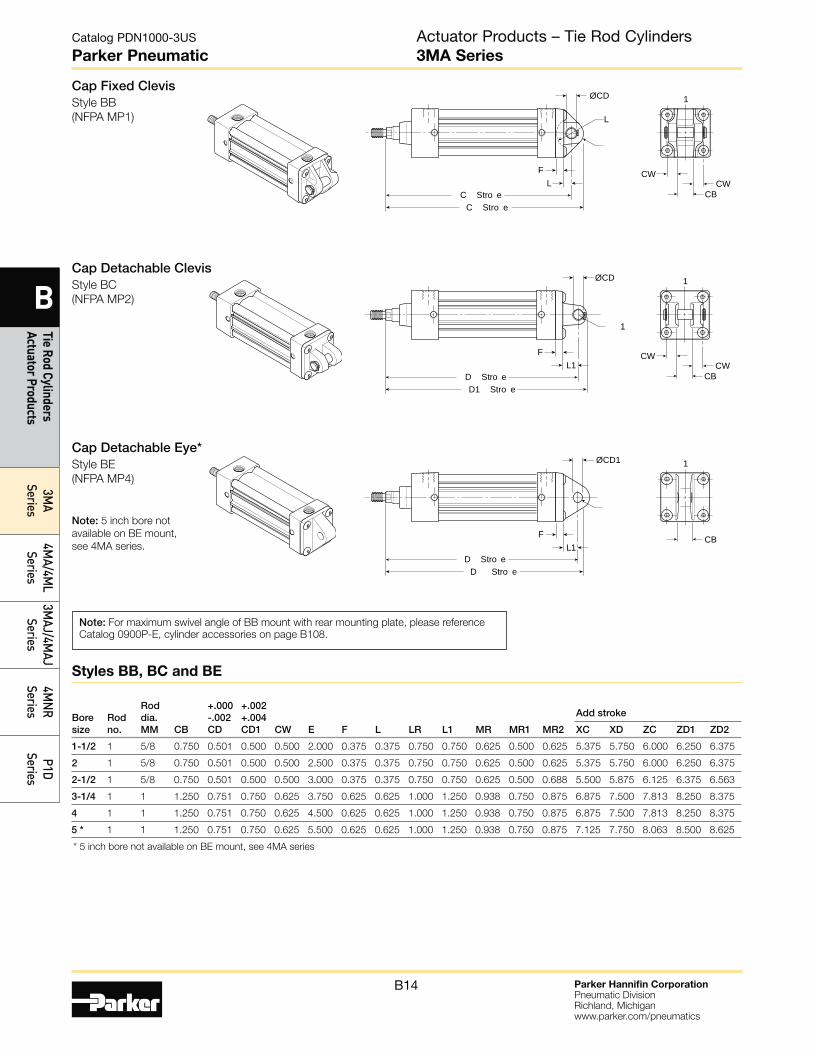
Cap Fixed ClevisStyle BB
(NFPA MP1)
CW
CBCW
1
C Stro eC Stro e
F
ØCD
L
L
Cap Detachable ClevisStyle BC
(NFPA MP2)
CW
CBCW
1
D1 Stro eD Stro e
F
1
L1
ØCD
Cap Detachable Eye*Style BE
(NFPA MP4)
Note: 5 inch bore not
available on BE mount,
see 4MA series.CB
1
D Stro eD Stro e
FL1
ØCD1
Note: For maximum swivel angle of BB mount with rear mounting plate, please reference
Catalog 0900P-E, cylinder accessories on page B108.
Bore size
Rod no.
Rod dia. MM CB
+.000 -.002 CD
+.002 +.004 CD1 CW E F L LR L1 MR MR1 MR2
Add stroke
XC XD ZC ZD1 ZD2
1-1/2 1 5/8 0.750 0.501 0.500 0.500 2.000 0.375 0.375 0.750 0.750 0.625 0.500 0.625 5.375 5.750 6.000 6.250 6.375
2 1 5/8 0.750 0.501 0.500 0.500 2.500 0.375 0.375 0.750 0.750 0.625 0.500 0.625 5.375 5.750 6.000 6.250 6.375
2-1/2 1 5/8 0.750 0.501 0.500 0.500 3.000 0.375 0.375 0.750 0.750 0.625 0.500 0.688 5.500 5.875 6.125 6.375 6.563
3-1/4 1 1 1.250 0.751 0.750 0.625 3.750 0.625 0.625 1.000 1.250 0.938 0.750 0.875 6.875 7.500 7.813 8.250 8.375
4 1 1 1.250 0.751 0.750 0.625 4.500 0.625 0.625 1.000 1.250 0.938 0.750 0.875 6.875 7.500 7.813 8.250 8.375
5 * 1 1 1.250 0.751 0.750 0.625 5.500 0.625 0.625 1.000 1.250 0.938 0.750 0.875 7.125 7.750 8.063 8.500 8.625
* 5 inch bore not available on BE mount, see 4MA series
Styles BB, BC and BE
Actuator Products – Tie Rod Cylinders3MA Series
Parker Hannifin CorporationPneumatic DivisionRichland, Michiganwww.parker.com/pneumatics
B15
Catalog PDN1000-3US
Parker Pneumatic
B
Tie
Rod
Cylin
ders
Ac
tuat
or P
rodu
cts
3MA
Serie
s4M
A/4M
L Se
ries
3MAJ
/4M
AJ
Serie
s4M
NR
Serie
sP1
D Se
ries
V
L L
Ø D
1BD
Stro e
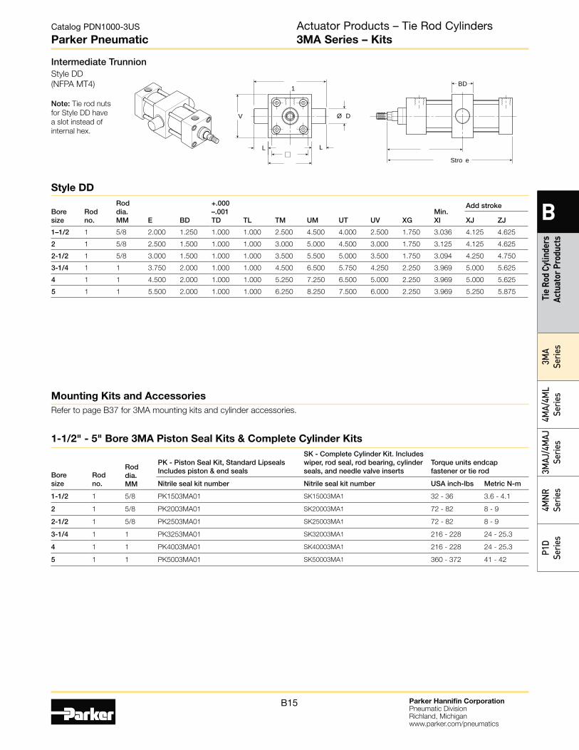
Intermediate TrunnionStyle DD
(NFPA MT4)
Note: Tie rod nuts
for Style DD have
a slot instead of
internal hex.
Bore size
Rod no.
Rod dia. MM E BD
+.000 –.001 TD TL TM UM UT UV XG
Min. XI
Add stroke
XJ ZJ
1–1/2 1 5/8 2.000 1.250 1.000 1.000 2.500 4.500 4.000 2.500 1.750 3.036 4.125 4.625
2 1 5/8 2.500 1.500 1.000 1.000 3.000 5.000 4.500 3.000 1.750 3.125 4.125 4.625
2-1/2 1 5/8 3.000 1.500 1.000 1.000 3.500 5.500 5.000 3.500 1.750 3.094 4.250 4.750
3-1/4 1 1 3.750 2.000 1.000 1.000 4.500 6.500 5.750 4.250 2.250 3.969 5.000 5.625
4 1 1 4.500 2.000 1.000 1.000 5.250 7.250 6.500 5.000 2.250 3.969 5.000 5.625
5 1 1 5.500 2.000 1.000 1.000 6.250 8.250 7.500 6.000 2.250 3.969 5.250 5.875
Style DD
Actuator Products – Tie Rod Cylinders3MA Series – Kits
Mounting Kits and Accessories
Refer to page B37 for 3MA mounting kits and cylinder accessories.
1-1/2" - 5" Bore 3MA Piston Seal Kits & Complete Cylinder Kits
Bore size
Rod no.
Rod dia. MM
PK - Piston Seal Kit, Standard Lipseals Includes piston & end seals
SK - Complete Cylinder Kit. Includes wiper, rod seal, rod bearing, cylinder seals, and needle valve inserts
Torque units endcap fastener or tie rod
Nitrile seal kit number Nitrile seal kit number USA inch-lbs Metric N-m
1-1/2 1 5/8 PK1503MA01 SK15003MA1 32 - 36 3.6 - 4.1
2 1 5/8 PK2003MA01 SK20003MA1 72 - 82 8 - 9
2-1/2 1 5/8 PK2503MA01 SK25003MA1 72 - 82 8 - 9
3-1/4 1 1 PK3253MA01 SK32003MA1 216 - 228 24 - 25.3
4 1 1 PK4003MA01 SK40003MA1 216 - 228 24 - 25.3
5 1 1 PK5003MA01 SK50003MA1 360 - 372 41 - 42
Parker Hannifin CorporationPneumatic DivisionRichland, Michiganwww.parker.com/pneumatics
B16
Catalog PDN1000-3US
Parker Pneumatic
B
Tie Rod Cylinders Actuator Products
3MA
Series4M
A/4ML
Series3M
AJ/4MAJ
Series4M
NR
SeriesP1D
Series
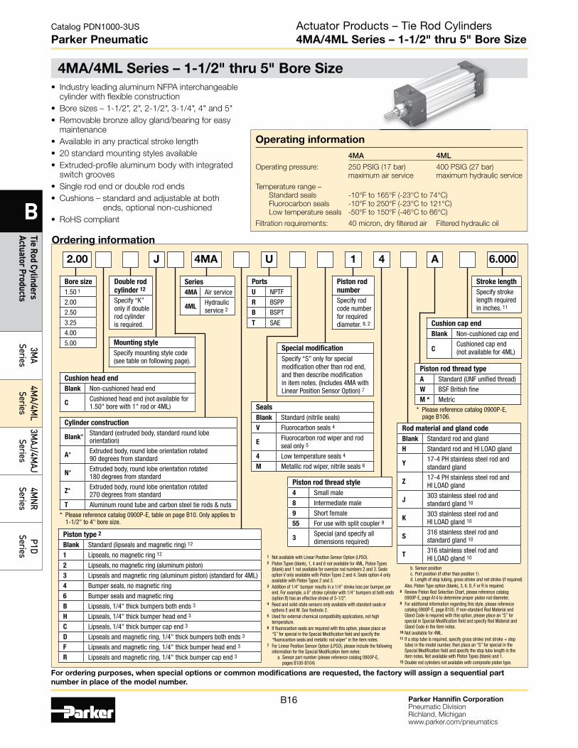
Actuator Products – Tie Rod Cylinders4MA/4ML Series – 1-1/2" thru 5" Bore Size
Operating information
4MA 4ML
Operating pressure: 250 PSIG (17 bar) 400 PSIG (27 bar)
maximum air service maximum hydraulic service
Temperature range –
Standard seals -10°F to 165°F (-23°C to 74°C)
Fluorocarbon seals -10°F to 250°F (-23°C to 121°C)
Low temperature seals -50°F to 150°F (-46°C to 66°C)
Filtration requirements: 40 micron, dry filtered air Filtered hydraulic oil
• Industry leading aluminum NFPA interchangeable cylinder with flexible construction
• Bore sizes – 1-1/2", 2", 2-1/2", 3-1/4", 4" and 5"
• Removable bronze alloy gland/bearing for easy maintenance
• Available in any practical stroke length
• 20 standard mounting styles available
• Extruded-profile aluminum body with integrated switch grooves
• Single rod end or double rod ends
• Cushions – standard and adjustable at both ends, optional non-cushioned
• RoHS compliant
Ordering information
J U 1 4 A 6.0002.00
1 Not available with Linear Position Sensor Option (LPSO).2 Piston Types (blank), 1, 4 and 6 not available for 4ML. Piston Types
(blank) and 1 not available for oversize rod numbers 2 and 3. Seals option V only available with Piston Types 2 and 4. Seals option 4 only available with Piston Types 2 and 3.
3 Addition of 1/4" bumper results in a 1/4" stroke loss per bumper, per end. For example, a 6" stroke cylinder with 1/4" bumpers at both ends (option B) has an effective stroke of 5-1/2".
4 Reed and solid-state sensors only available with standard seals or options E and M. See footnote 2.
5 Used for external chemical compatibility applications, not high temperature.
6 If fluorocarbon seals are required with this option, please place an “S” for special in the Special Modification field and specify the “fluorocarbon seals and metallic rod wiper” in the item notes.
7 For Linear Position Sensor Option (LPSO), please include the following information for the Special Modification item notes: a. Sensor part number (please reference catalog 0900P-E, pages B100-B104)
b. Sensor position c. Port position (if other than position 1) d. Length of stop tubing, gross stroke and net stroke (if required)
Also, Piston Type option (blank), 3, 6, D, F or R is required.8 Review Piston Rod Selection Chart, please reference catalog
0900P-E, page A14 to determine proper piston rod diameter.9 For additional information regarding this style, please reference
catalog 0900P-E, page B105. If non-standard Rod Material and Gland Code is required with this option, please place an “S” for special in Special Modification field and specify Rod Material and Gland Code in the item notes.
10 Not available for 4ML.11 If a stop tube is required, specify gross stroke (net stroke + stop
tube) in the model number, then place an “S” for special in the Special Modification field and specify the stop tube length in the item notes. Not available with Piston Types (blank) and 1.
12 Double rod cylinders not available with composite piston type.
Cylinder construction
Blank* Standard (extruded body, standard round lobe orientation)
A* Extruded body, round lobe orientation rotated 90 degrees from standard
N* Extruded body, round lobe orientation rotated 180 degrees from standard
Z* Extruded body, round lobe orientation rotated 270 degrees from standard
T Aluminum round tube and carbon steel tie rods & nuts* Please reference catalog 0900P-E, table on page B10. Only applies to
1-1/2" to 4" bore size.
Piston type 2
Blank Standard (lipseals and magnetic ring) 12
1 Lipseals, no magnetic ring 12
2 Lipseals, no magnetic ring (aluminum piston)
3 Lipseals and magnetic ring (aluminum piston) (standard for 4ML)
4 Bumper seals, no magnetic ring
6 Bumper seals and magnetic ring
B Lipseals, 1/4" thick bumpers both ends 3
H Lipseals, 1/4" thick bumper head end 3
C Lipseals, 1/4" thick bumper cap end 3
D Lipseals and magnetic ring, 1/4" thick bumpers both ends 3
F Lipseals and magnetic ring, 1/4" thick bumper head end 3
R Lipseals and magnetic ring, 1/4" thick bumper cap end 3
Bore size
1.50 1
2.00
2.50
3.25
4.00
5.00
Stroke length
Specify stroke length required in inches. 11
Mounting style
Specify mounting style code (see table on following page).
Double rod
cylinder 12
Specify “K” only if double rod cylinder is required.
Piston rod
number
Specify rod code number for required diameter. 8, 2
Ports
U NPTF
R BSPP
B BSPT
T SAE
Cushion head end
Blank Non-cushioned head end
CCushioned head end (not available for 1.50" bore with 1" rod or 4ML)
Cushion cap end
Blank Non-cushioned cap end
CCushioned cap end (not available for 4ML)
Piston rod thread type
A Standard (UNF unified thread)
W BSF British fine
M * Metric* Please reference catalog 0900P-E,
page B106.
Rod material and gland code
Blank Standard rod and gland
H Standard rod and HI LOAD gland
Y17-4 PH stainless steel rod and standard gland
Z17-4 PH stainless steel rod and HI LOAD gland
J303 stainless steel rod and standard gland 10
K303 stainless steel rod and HI LOAD gland 10
S316 stainless steel rod and standard gland 10
T316 stainless steel rod and HI LOAD gland 10
Piston rod thread style
4 Small male
8 Intermediate male
9 Short female
55 For use with split coupler 9
3Special (and specify all dimensions required)
Seals
Blank Standard (nitrile seals)
V Fluorocarbon seals 4
EFluorocarbon rod wiper and rod seal only 5
4 Low temperature seals 4
M Metallic rod wiper, nitrile seals 6
Series
4MA Air service
4MLHydraulic service 2
Special modification
Specify “S” only for special modification other than rod end, and then describe modification in item notes. (Includes 4MA with Linear Position Sensor Option) 7
4MA
4MA/4ML Series – 1-1/2" thru 5" Bore Size
For ordering purposes, when special options or common modifications are requested, the factory will assign a sequential part
number in place of the model number.
Parker Hannifin CorporationPneumatic DivisionRichland, Michiganwww.parker.com/pneumatics
B17
B
Tie
Rod
Cylin
ders
Ac
tuat
or P
rodu
cts
3MA
Serie
s4M
A/4M
L Se
ries
3MAJ
/4M
AJ
Serie
s4M
NR
Serie
sP1
D Se
ries
Catalog PDN1000-3US
Parker Pneumatic
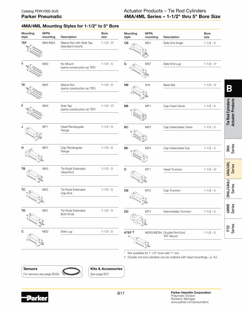
Mounting style
NFPA mounting Description
Bore size
CB MS1 Side End Angle 1-1/2 - 5
G MS7 Side End Lug 1-1/2 - 4*
NB N/A Base Bar 1-1/2 - 4*
BB MP1 Cap Fixed Clevis 1-1/2 - 5
BC MP2 Cap Detachable Clevis 1-1/2 - 5
BE MP4 Cap Detachable Eye 1-1/2 - 5
D MT1 Head Trunnion 1-1/2 - 5*
DB MT2 Cap Trunnion 1-1/2 - 5
DD MT4 Intermediate Trunnion 1-1/2 - 5
KTEF † MDX5/MDS4 Double Rod End,
TEF Mount
1-1/2 - 5
* Not available for 1-1/2" bore with 1" rod.
† Double rod end cylinders can be ordered with head mountings, i.e. KJ.
Mounting style
NFPA mounting Description
Bore size
TEF MX5/MS4 Sleeve Nut with Side Tap
(standard mount)
1-1/2 - 5*
T MX0 No Mount
(same construction as TEF)
1-1/2 - 5
TE MX5 Sleeve Nut
(same construction as TEF)
1-1/2 - 5
F MS4 Side Tap
(same construction as TEF)
1-1/2 - 5*
J MF1 Head Rectangular
Flange
1-1/2 - 5
H MF2 Cap Rectangular
Flange
1-1/2 - 5
TB MX3 Tie Rods Extended
Head End
1-1/2 - 5
TC MX2 Tie Rods Extended
Cap End
1-1/2 - 5
TD MX1 Tie Rods Extended
Both Ends
1-1/2 - 5
C MS2 Side Lug 1-1/2 - 5
Actuator Products – Tie Rod Cylinders4MA/4ML Series – 1-1/2" thru 5" Bore Size
4MA/4ML Mounting Styles for 1-1/2" to 5" Bore
Sensors
For sensors see page B339.
Kits & Accessories
See page B37.
Parker Hannifin CorporationPneumatic DivisionRichland, Michiganwww.parker.com/pneumatics
B18
Catalog PDN1000-3US
Parker Pneumatic
B
Tie Rod Cylinders Actuator Products
3MA
Series4M
A/4ML
Series3M
AJ/4MAJ
Series4M
NR
SeriesP1D
Series
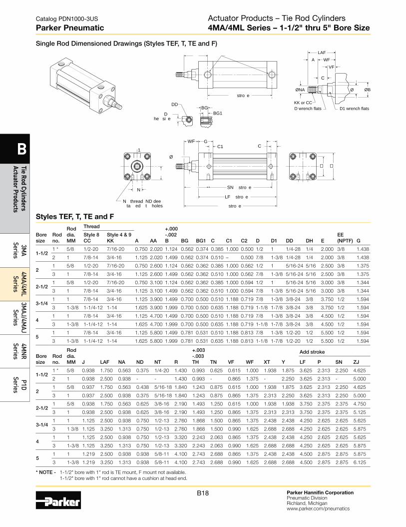
Single Rod Dimensioned Drawings (Styles TEF, T, TE and F)
* NOTE - 1-1/2" bore with 1" rod is TE mount, F mount not available.
1-1/2" bore with 1" rod cannot have a cushion at head end.
Boresize
Rodno.
Roddia.MM
Thread
A AA
+.000-.002B BG BG1 C C1 C2 D D1 DD DH E
EE(NPTF) G
Style 8CC
Style 4 & 9KK
1-1/21 * 5/8 1/2-20 7/16-20 0.750 2.020 1.124 0.562 0.374 0.385 1.000 0.500 1/2 1 1/4-28 1/4 2.000 3/8 1.438
2 1 7/8-14 3/4-16 1.125 2.020 1.499 0.562 0.374 0.510 – 0.500 7/8 1-3/8 1/4-28 1/4 2.000 3/8 1.438
21 5/8 1/2-20 7/16-20 0.750 2.600 1.124 0.562 0.362 0.385 1.000 0.562 1/2 1 5/16-24 5/16 2.500 3/8 1.375
3 1 7/8-14 3/4-16 1.125 2.600 1.499 0.562 0.362 0.510 1.000 0.562 7/8 1-3/8 5/16-24 5/16 2.500 3/8 1.375
2-1/21 5/8 1/2-20 7/16-20 0.750 3.100 1.124 0.562 0.362 0.385 1.000 0.594 1/2 1 5/16-24 5/16 3.000 3/8 1.344
3 1 7/8-14 3/4-16 1.125 3.100 1.499 0.562 0.362 0.510 1.000 0.594 7/8 1-3/8 5/16-24 5/16 3.000 3/8 1.344
3-1/41 1 7/8-14 3/4-16 1.125 3.900 1.499 0.700 0.500 0.510 1.188 0.719 7/8 1-3/8 3/8-24 3/8 3.750 1/2 1.594
3 1-3/8 1-1/4-12 1-14 1.625 3.900 1.999 0.700 0.500 0.635 1.188 0.719 1-1/8 1-7/8 3/8-24 3/8 3.750 1/2 1.594
41 1 7/8-14 3/4-16 1.125 4.700 1.499 0.700 0.500 0.510 1.188 0.719 7/8 1-3/8 3/8-24 3/8 4.500 1/2 1.594
3 1-3/8 1-1/4-12 1-14 1.625 4.700 1.999 0.700 0.500 0.635 1.188 0.719 1-1/8 1-7/8 3/8-24 3/8 4.500 1/2 1.594
51 1 7/8-14 3/4-16 1.125 5.800 1.499 0.781 0.531 0.510 1.188 0.813 7/8 1-3/8 1/2-20 1/2 5.500 1/2 1.594
3 1-3/8 1-1/4-12 1-14 1.625 5.800 1.999 0.781 0.531 0.635 1.188 0.813 1-1/8 1-7/8 1/2-20 1/2 5.500 1/2 1.594
Boresize
Rodno.
Roddia.MM J LAF NA ND NT R
+.003-.003TH TN VF WF XT Y
Add stroke
LF P SN ZJ
1-1/2 1 * 5/8 0.938 1.750 0.563 0.375 1/4-20 1.430 0.993 0.625 0.615 1.000 1.938 1.875 3.625 2.313 2.250 4.625
2 1 0.938 2.500 0.938 - - 1.430 0.993 - 0.865 1.375 - 2.250 3.625 2.313 - 5.000
21 5/8 0.937 1.750 0.563 0.438 5/16-18 1.840 1.243 0.875 0.615 1.000 1.938 1.875 3.625 2.313 2.250 4.625
3 1 0.937 2.500 0.938 0.375 5/16-18 1.840 1.243 0.875 0.865 1.375 2.313 2.250 3.625 2.313 2.250 5.000
2-1/2 1 5/8 0.938 1.750 0.563 0.625 3/8-16 2.190 1.493 1.250 0.615 1.000 1.938 1.938 3.750 2.375 2.375 4.750
3 1 0.938 2.500 0.938 0.625 3/8-16 2.190 1.493 1.250 0.865 1.375 2.313 2.313 3.750 2.375 2.375 5.125
3-1/4 1 1 1.125 2.500 0.938 0.750 1/2-13 2.760 1.868 1.500 0.865 1.375 2.438 2.438 4.250 2.625 2.625 5.625
3 1 3/8 1.125 3.250 1.313 0.750 1/2-13 2.760 1.868 1.500 0.990 1.625 2.688 2.688 4.250 2.625 2.625 5.875
4 1 1 1.125 2.500 0.938 0.750 1/2-13 3.320 2.243 2.063 0.865 1.375 2.438 2.438 4.250 2.625 2.625 5.625
3 1-3/8 1.125 3.250 1.313 0.750 1/2-13 3.320 2.243 2.063 0.990 1.625 2.688 2.688 4.250 2.625 2.625 5.875
5 1 1 1.219 2.500 0.938 0.938 5/8-11 4.100 2.743 2.688 0.865 1.375 2.438 2.438 4.500 2.875 2.875 5.875
3 1-3/8 1.219 3.250 1.313 0.938 5/8-11 4.100 2.743 2.688 0.990 1.625 2.688 2.688 4.500 2.875 2.875 6.125
Ø
C1 C
N
N thread ND dee ta ed t holes
SN stro e
1
WF G
LF stro e
stro e
BGBG1
DD
D he si e
stro eKK or CCD wrench flats D1 wrench flats
WFVF
C
LAFA
ØNA ØBØ
Styles TEF, T, TE and F
Actuator Products – Tie Rod Cylinders4MA/4ML Series – 1-1/2" thru 5" Bore Size
Parker Hannifin CorporationPneumatic DivisionRichland, Michiganwww.parker.com/pneumatics
B19
Catalog PDN1000-3US
Parker Pneumatic
B
Tie
Rod
Cylin
ders
Ac
tuat
or P
rodu
cts
3MA
Serie
s4M
A/4M
L Se
ries
3MAJ
/4M
AJ
Serie
s4M
NR
Serie
sP1
D Se
ries
KK
D wrench flats
WF
VF
C
A
KKD wrench flats D1 wrench flats
WF
VF
C
LAF
A
CCD wrench flats D1 wrench flats
WF
VF
C
LAF
A
D1 wrench flats D1 wrench flats
Groove has 1/16"internal radii at corners
VF
VSØ1/16
Ø A
WGAD
AØAF
ØNA ØBØ ØBØ
ØNA ØBØ ØNA ØBØ
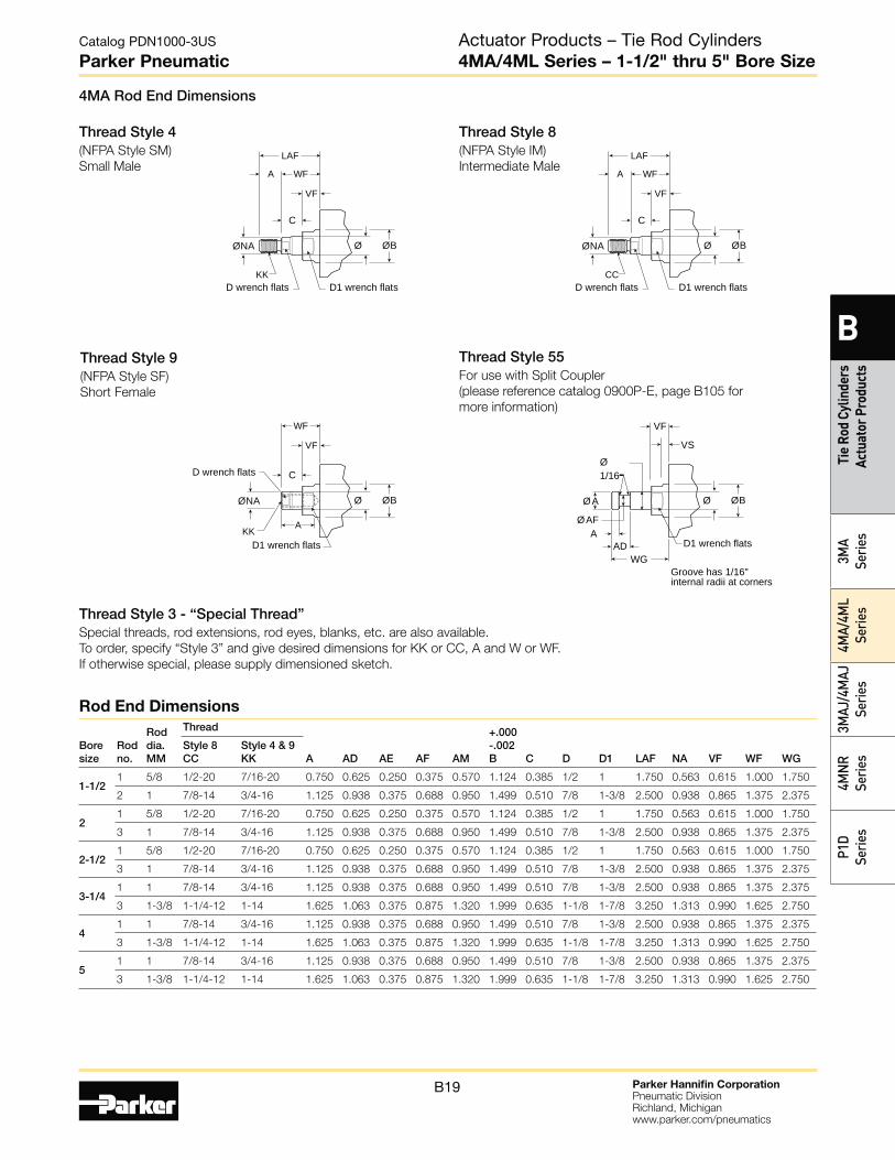
Rod End Dimensions
4MA Rod End Dimensions
Thread Style 4(NFPA Style SM)
Small Male
Thread Style 8(NFPA Style IM)
Intermediate Male
Thread Style 9(NFPA Style SF)
Short Female
Thread Style 55For use with Split Coupler
(please reference catalog 0900P-E, page B105 for
more information)
Thread Style 3 - “Special Thread”Special threads, rod extensions, rod eyes, blanks, etc. are also available.
To order, specify “Style 3” and give desired dimensions for KK or CC, A and W or WF.
If otherwise special, please supply dimensioned sketch.
Boresize
Rodno.
Roddia.MM
Thread
A AD AE AF AM
+.000-.002B C D D1 LAF NA VF WF WG
Style 8CC
Style 4 & 9KK
1-1/21 5/8 1/2-20 7/16-20 0.750 0.625 0.250 0.375 0.570 1.124 0.385 1/2 1 1.750 0.563 0.615 1.000 1.750
2 1 7/8-14 3/4-16 1.125 0.938 0.375 0.688 0.950 1.499 0.510 7/8 1-3/8 2.500 0.938 0.865 1.375 2.375
21 5/8 1/2-20 7/16-20 0.750 0.625 0.250 0.375 0.570 1.124 0.385 1/2 1 1.750 0.563 0.615 1.000 1.750
3 1 7/8-14 3/4-16 1.125 0.938 0.375 0.688 0.950 1.499 0.510 7/8 1-3/8 2.500 0.938 0.865 1.375 2.375
2-1/21 5/8 1/2-20 7/16-20 0.750 0.625 0.250 0.375 0.570 1.124 0.385 1/2 1 1.750 0.563 0.615 1.000 1.750
3 1 7/8-14 3/4-16 1.125 0.938 0.375 0.688 0.950 1.499 0.510 7/8 1-3/8 2.500 0.938 0.865 1.375 2.375
3-1/41 1 7/8-14 3/4-16 1.125 0.938 0.375 0.688 0.950 1.499 0.510 7/8 1-3/8 2.500 0.938 0.865 1.375 2.375
3 1-3/8 1-1/4-12 1-14 1.625 1.063 0.375 0.875 1.320 1.999 0.635 1-1/8 1-7/8 3.250 1.313 0.990 1.625 2.750
41 1 7/8-14 3/4-16 1.125 0.938 0.375 0.688 0.950 1.499 0.510 7/8 1-3/8 2.500 0.938 0.865 1.375 2.375
3 1-3/8 1-1/4-12 1-14 1.625 1.063 0.375 0.875 1.320 1.999 0.635 1-1/8 1-7/8 3.250 1.313 0.990 1.625 2.750
51 1 7/8-14 3/4-16 1.125 0.938 0.375 0.688 0.950 1.499 0.510 7/8 1-3/8 2.500 0.938 0.865 1.375 2.375
3 1-3/8 1-1/4-12 1-14 1.625 1.063 0.375 0.875 1.320 1.999 0.635 1-1/8 1-7/8 3.250 1.313 0.990 1.625 2.750
Actuator Products – Tie Rod Cylinders4MA/4ML Series – 1-1/2" thru 5" Bore Size
Parker Hannifin CorporationPneumatic DivisionRichland, Michiganwww.parker.com/pneumatics
B20
Catalog PDN1000-3US
Parker Pneumatic
B
Tie Rod Cylinders Actuator Products
3MA
Series4M
A/4ML
Series3M
AJ/4MAJ
Series4M
NR
SeriesP1D
Series
F
1
F
FB oles
F Stro e
1 WLA LB Stro e
F
1
F
FB oles
FF Stro e
1
Stro e
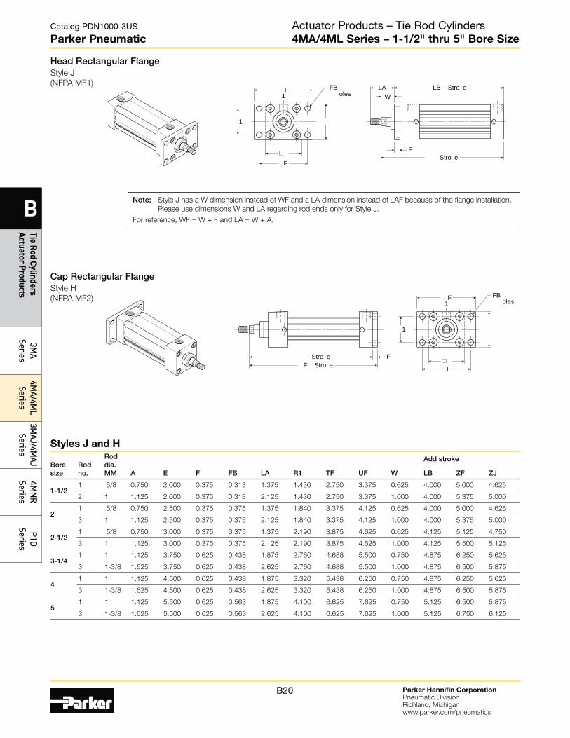
Head Rectangular FlangeStyle J
(NFPA MF1)
Cap Rectangular FlangeStyle H
(NFPA MF2)
Note: Style J has a W dimension instead of WF and a LA dimension instead of LAF because of the flange installation.
Please use dimensions W and LA regarding rod ends only for Style J.
For reference, WF = W + F and LA = W + A.
Boresize
Rodno.
Roddia.MM A E F FB LA R1 TF UF W
Add stroke
LB ZF ZJ
1-1/21 5/8 0.750 2.000 0.375 0.313 1.375 1.430 2.750 3.375 0.625 4.000 5.000 4.625
2 1 1.125 2.000 0.375 0.313 2.125 1.430 2.750 3.375 1.000 4.000 5.375 5.000
21 5/8 0.750 2.500 0.375 0.375 1.375 1.840 3.375 4.125 0.625 4.000 5.000 4.625
3 1 1.125 2.500 0.375 0.375 2.125 1.840 3.375 4.125 1.000 4.000 5.375 5.000
2-1/21 5/8 0.750 3.000 0.375 0.375 1.375 2.190 3.875 4.625 0.625 4.125 5.125 4.750
3 1 1.125 3.000 0.375 0.375 2.125 2.190 3.875 4.625 1.000 4.125 5.500 5.125
3-1/41 1 1.125 3.750 0.625 0.438 1.875 2.760 4.688 5.500 0.750 4.875 6.250 5.625
3 1-3/8 1.625 3.750 0.625 0.438 2.625 2.760 4.688 5.500 1.000 4.875 6.500 5.875
41 1 1.125 4.500 0.625 0.438 1.875 3.320 5.438 6.250 0.750 4.875 6.250 5.625
3 1-3/8 1.625 4.500 0.625 0.438 2.625 3.320 5.438 6.250 1.000 4.875 6.500 5.875
51 1 1.125 5.500 0.625 0.563 1.875 4.100 6.625 7.625 0.750 5.125 6.500 5.875
3 1-3/8 1.625 5.500 0.625 0.563 2.625 4.100 6.625 7.625 1.000 5.125 6.750 6.125
Styles J and H
Actuator Products – Tie Rod Cylinders4MA/4ML Series – 1-1/2" thru 5" Bore Size
Parker Hannifin CorporationPneumatic DivisionRichland, Michiganwww.parker.com/pneumatics
B21
Catalog PDN1000-3US
Parker Pneumatic
B
Tie
Rod
Cylin
ders
Ac
tuat
or P
rodu
cts
3MA
Serie
s4M
A/4M
L Se
ries
3MAJ
/4M
AJ
Serie
s4M
NR
Serie
sP1
D Se
ries
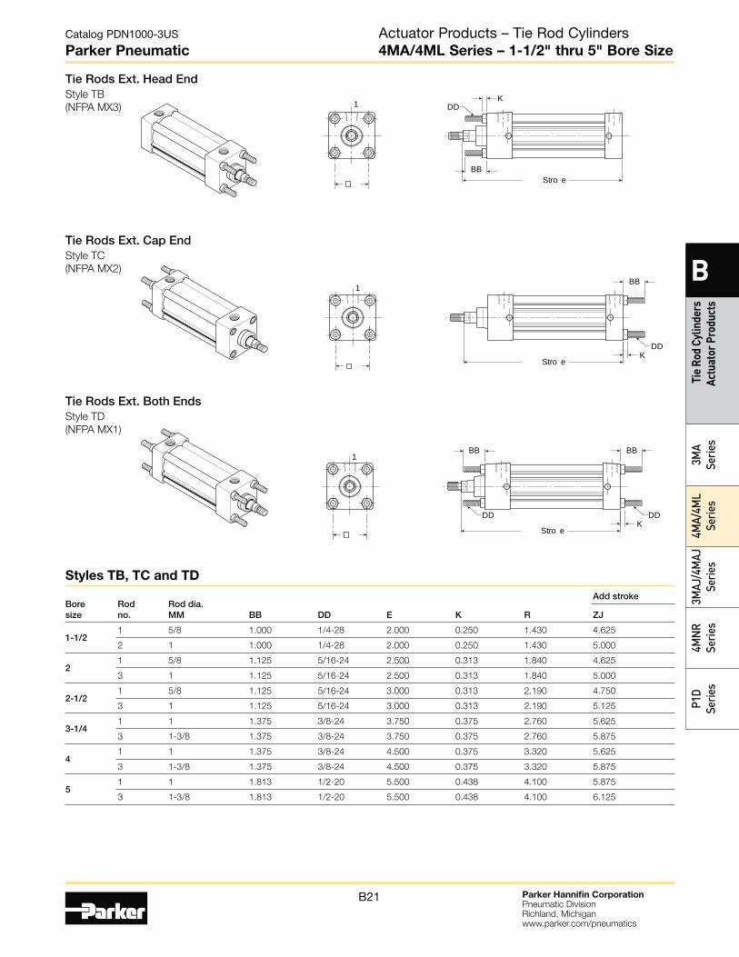
Tie Rods Ext. Head EndStyle TB
(NFPA MX3)
1BB
Stro e
DDK
1
BB Stro e
DDK
1BBBB
Stro e
DDDDK
Tie Rods Ext. Both EndsStyle TD
(NFPA MX1)
Tie Rods Ext. Cap EndStyle TC
(NFPA MX2)
Bore size
Rod no.
Rod dia. MM BB DD E K R
Add stroke
ZJ
1-1/2 1 5/8 1.000 1/4-28 2.000 0.250 1.430 4.625
2 1 1.000 1/4-28 2.000 0.250 1.430 5.000
2 1 5/8 1.125 5/16-24 2.500 0.313 1.840 4.625
3 1 1.125 5/16-24 2.500 0.313 1.840 5.000
2-1/2 1 5/8 1.125 5/16-24 3.000 0.313 2.190 4.750
3 1 1.125 5/16-24 3.000 0.313 2.190 5.125
3-1/4 1 1 1.375 3/8-24 3.750 0.375 2.760 5.625
3 1-3/8 1.375 3/8-24 3.750 0.375 2.760 5.875
4 1 1 1.375 3/8-24 4.500 0.375 3.320 5.625
3 1-3/8 1.375 3/8-24 4.500 0.375 3.320 5.875
5 1 1 1.813 1/2-20 5.500 0.438 4.100 5.875
3 1-3/8 1.813 1/2-20 5.500 0.438 4.100 6.125
Styles TB, TC and TD
Actuator Products – Tie Rod Cylinders4MA/4ML Series – 1-1/2" thru 5" Bore Size
Parker Hannifin CorporationPneumatic DivisionRichland, Michiganwww.parker.com/pneumatics
B22
Catalog PDN1000-3US
Parker Pneumatic
B
Tie Rod Cylinders Actuator Products
3MA
Series4M
A/4ML
Series3M
AJ/4MAJ
Series4M
NR
SeriesP1D
Series
A
A
AA
ALF
A
A
AL1
AB6 oles
A Stro eA Stro e
1
SA Stro e
S
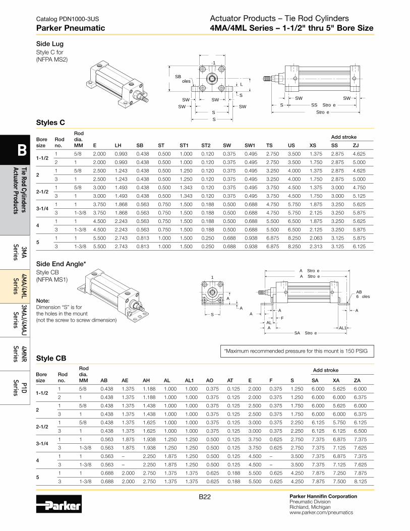
Side End Angle*Style CB
(NFPA MS1)
Note: Dimension “S” is for
the holes in the mount
(not the screw to screw dimension)
*Maximum recommended pressure for this mount is 150 PSIG
Bore size
Rod no.
Rod dia. MM AB AE AH AL AL1 AO AT E F S
Add stroke
SA XA ZA
1-1/2 1 5/8 0.438 1.375 1.188 1.000 1.000 0.375 0.125 2.000 0.375 1.250 6.000 5.625 6.000
2 1 0.438 1.375 1.188 1.000 1.000 0.375 0.125 2.000 0.375 1.250 6.000 6.000 6.375
2 1 5/8 0.438 1.375 1.438 1.000 1.000 0.375 0.125 2.500 0.375 1.750 6.000 5.625 6.000
3 1 0.438 1.375 1.438 1.000 1.000 0.375 0.125 2.500 0.375 1.750 6.000 6.000 6.375
2-1/2 1 5/8 0.438 1.375 1.625 1.000 1.000 0.375 0.125 3.000 0.375 2.250 6.125 5.750 6.125
3 1 0.438 1.375 1.625 1.000 1.000 0.375 0.125 3.000 0.375 2.250 6.125 6.125 6.500
3-1/4 1 1 0.563 1.875 1.938 1.250 1.250 0.500 0.125 3.750 0.625 2.750 7.375 6.875 7.375
3 1-3/8 0.563 1.875 1.938 1.250 1.250 0.500 0.125 3.750 0.625 2.750 7.375 7.125 7.625
4 1 1 0.563 – 2.250 1.875 1.250 0.500 0.125 4.500 – 3.500 7.375 6.875 7.375
3 1-3/8 0.563 – 2.250 1.875 1.250 0.500 0.125 4.500 – 3.500 7.375 7.125 7.625
5 1 1 0.688 2.000 2.750 1.375 1.375 0.625 0.188 5.500 0.625 4.250 7.875 7.250 7.875
3 1-3/8 0.688 2.000 2.750 1.375 1.375 0.625 0.188 5.500 0.625 4.250 7.875 7.500 8.125
Style CB
SW
SS
L
S
S
SB oles
SWSWSW SW
SW
Stro eSS Stro e
1
Side LugStyle C for
(NFPA MS2)
Bore size
Rod no.
Rod dia. MM E LH SB ST ST1 ST2 SW SW1 TS US XS
Add stroke
SS ZJ
1-1/2 1 5/8 2.000 0.993 0.438 0.500 1.000 0.120 0.375 0.495 2.750 3.500 1.375 2.875 4.625
2 1 2.000 0.993 0.438 0.500 1.000 0.120 0.375 0.495 2.750 3.500 1.750 2.875 5.000
2 1 5/8 2.500 1.243 0.438 0.500 1.250 0.120 0.375 0.495 3.250 4.000 1.375 2.875 4.625
3 1 2.500 1.243 0.438 0.500 1.250 0.120 0.375 0.495 3.250 4.000 1.750 2.875 5.000
2-1/2 1 5/8 3.000 1.493 0.438 0.500 1.343 0.120 0.375 0.495 3.750 4.500 1.375 3.000 4.750
3 1 3.000 1.493 0.438 0.500 1.343 0.120 0.375 0.495 3.750 4.500 1.750 3.000 5.125
3-1/4 1 1 3.750 1.868 0.563 0.750 1.500 0.188 0.500 0.688 4.750 5.750 1.875 3.250 5.625
3 1-3/8 3.750 1.868 0.563 0.750 1.500 0.188 0.500 0.688 4.750 5.750 2.125 3.250 5.875
4 1 1 4.500 2.243 0.563 0.750 1.500 0.188 0.500 0.688 5.500 6.500 1.875 3.250 5.625
3 1-3/8 4.500 2.243 0.563 0.750 1.500 0.188 0.500 0.688 5.500 6.500 2.125 3.250 5.875
5 1 1 5.500 2.743 0.813 1.000 1.500 0.250 0.688 0.938 6.875 8.250 2.063 3.125 5.875
3 1-3/8 5.500 2.743 0.813 1.000 1.500 0.250 0.688 0.938 6.875 8.250 2.313 3.125 6.125
Styles C
Actuator Products – Tie Rod Cylinders4MA/4ML Series – 1-1/2" thru 5" Bore Size
Parker Hannifin CorporationPneumatic DivisionRichland, Michiganwww.parker.com/pneumatics
B23
Catalog PDN1000-3US
Parker Pneumatic
B
Tie
Rod
Cylin
ders
Ac
tuat
or P
rodu
cts
3MA
Serie
s4M
A/4M
L Se
ries
3MAJ
/4M
AJ
Serie
s4M
NR
Serie
sP1
D Se
ries
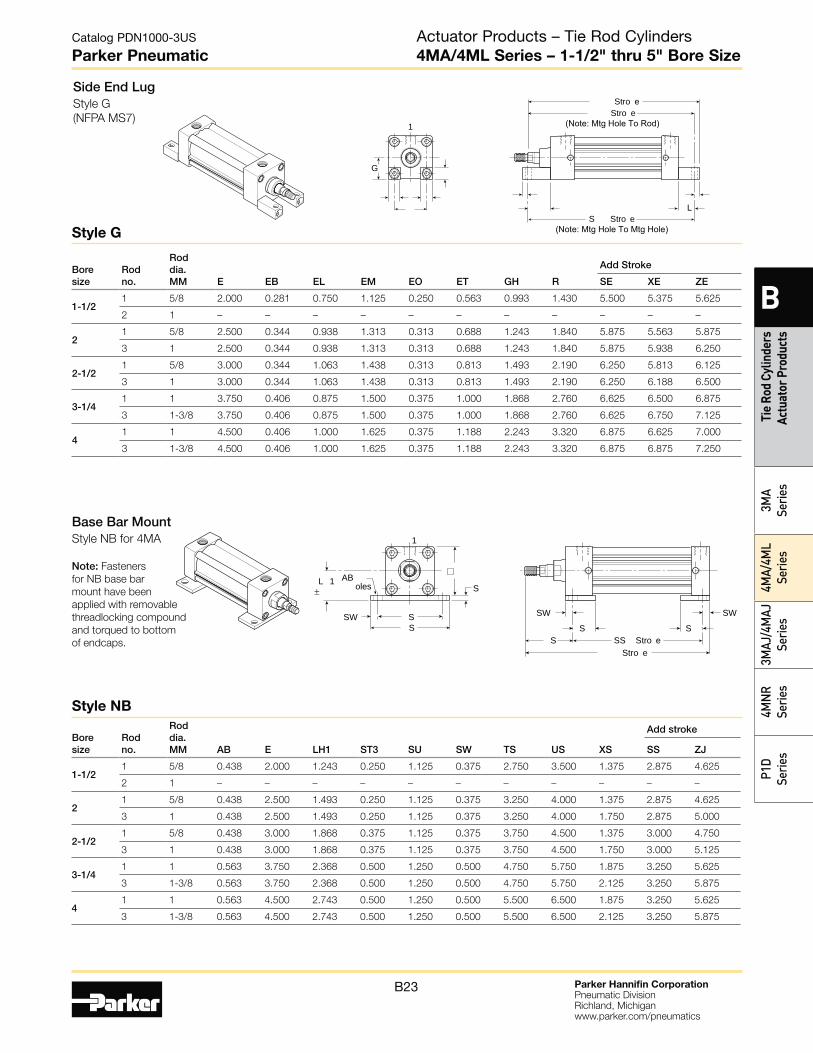
Side End LugStyle G
(NFPA MS7)
G
L
Stro e
1
S Stro e(Note: Mtg Hole To Mtg Hole)
Stro e(Note: Mtg Hole To Rod)
Bore size
Rod no.
Rod dia. MM E EB EL EM EO ET GH R
Add Stroke
SE XE ZE
1-1/2 1 5/8 2.000 0.281 0.750 1.125 0.250 0.563 0.993 1.430 5.500 5.375 5.625
2 1 – – – – – – – – – – –
2 1 5/8 2.500 0.344 0.938 1.313 0.313 0.688 1.243 1.840 5.875 5.563 5.875
3 1 2.500 0.344 0.938 1.313 0.313 0.688 1.243 1.840 5.875 5.938 6.250
2-1/2 1 5/8 3.000 0.344 1.063 1.438 0.313 0.813 1.493 2.190 6.250 5.813 6.125
3 1 3.000 0.344 1.063 1.438 0.313 0.813 1.493 2.190 6.250 6.188 6.500
3-1/4 1 1 3.750 0.406 0.875 1.500 0.375 1.000 1.868 2.760 6.625 6.500 6.875
3 1-3/8 3.750 0.406 0.875 1.500 0.375 1.000 1.868 2.760 6.625 6.750 7.125
4 1 1 4.500 0.406 1.000 1.625 0.375 1.188 2.243 3.320 6.875 6.625 7.000
3 1-3/8 4.500 0.406 1.000 1.625 0.375 1.188 2.243 3.320 6.875 6.875 7.250
Style G
Base Bar MountStyle NB for 4MA
Note: Fasteners
for NB base bar
mount have been
applied with removable
threadlocking compound
and torqued to bottom
of endcaps.
AB oles S
L 1±
SW SS S
S
SW
Stro e
SSW
SS Stro e
1
Bore size
Rod no.
Rod dia. MM AB E LH1 ST3 SU SW TS US XS
Add stroke
SS ZJ
1-1/2 1 5/8 0.438 2.000 1.243 0.250 1.125 0.375 2.750 3.500 1.375 2.875 4.625
2 1 – – – – – – – – – – –
2 1 5/8 0.438 2.500 1.493 0.250 1.125 0.375 3.250 4.000 1.375 2.875 4.625
3 1 0.438 2.500 1.493 0.250 1.125 0.375 3.250 4.000 1.750 2.875 5.000
2-1/2 1 5/8 0.438 3.000 1.868 0.375 1.125 0.375 3.750 4.500 1.375 3.000 4.750
3 1 0.438 3.000 1.868 0.375 1.125 0.375 3.750 4.500 1.750 3.000 5.125
3-1/4 1 1 0.563 3.750 2.368 0.500 1.250 0.500 4.750 5.750 1.875 3.250 5.625
3 1-3/8 0.563 3.750 2.368 0.500 1.250 0.500 4.750 5.750 2.125 3.250 5.875
4 1 1 0.563 4.500 2.743 0.500 1.250 0.500 5.500 6.500 1.875 3.250 5.625
3 1-3/8 0.563 4.500 2.743 0.500 1.250 0.500 5.500 6.500 2.125 3.250 5.875
Style NB
Actuator Products – Tie Rod Cylinders4MA/4ML Series – 1-1/2" thru 5" Bore Size
Parker Hannifin CorporationPneumatic DivisionRichland, Michiganwww.parker.com/pneumatics
B24
Catalog PDN1000-3US
Parker Pneumatic
B
Tie Rod Cylinders Actuator Products
3MA
Series4M
A/4ML
Series3M
AJ/4MAJ
Series4M
NR
SeriesP1D
Series
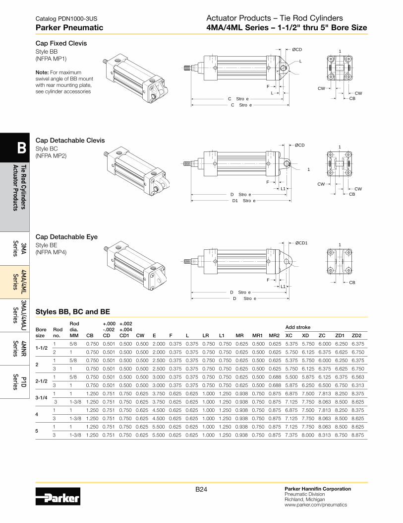
Cap Fixed ClevisStyle BB
(NFPA MP1)
Note: For maximum
swivel angle of BB mount
with rear mounting plate,
see cylinder accessoriesCW
CBCW
1
C Stro eC Stro e
F
ØCD
L
L
Cap Detachable ClevisStyle BC
(NFPA MP2)
CW
CBCW
1
D1 Stro eD Stro e
F
1
L1
ØCD
Cap Detachable EyeStyle BE
(NFPA MP4)
CB
1
D Stro eD Stro e
FL1
ØCD1
Bore size
Rod no.
Rod dia. MM CB
+.000 -.002 CD
+.002 +.004 CD1 CW E F L LR L1 MR MR1 MR2
Add stroke
XC XD ZC ZD1 ZD2
1-1/2 1 5/8 0.750 0.501 0.500 0.500 2.000 0.375 0.375 0.750 0.750 0.625 0.500 0.625 5.375 5.750 6.000 6.250 6.375
2 1 0.750 0.501 0.500 0.500 2.000 0.375 0.375 0.750 0.750 0.625 0.500 0.625 5.750 6.125 6.375 6.625 6.750
2 1 5/8 0.750 0.501 0.500 0.500 2.500 0.375 0.375 0.750 0.750 0.625 0.500 0.625 5.375 5.750 6.000 6.250 6.375
3 1 0.750 0.501 0.500 0.500 2.500 0.375 0.375 0.750 0.750 0.625 0.500 0.625 5.750 6.125 6.375 6.625 6.750
2-1/2 1 5/8 0.750 0.501 0.500 0.500 3.000 0.375 0.375 0.750 0.750 0.625 0.500 0.688 5.500 5.875 6.125 6.375 6.563
3 1 0.750 0.501 0.500 0.500 3.000 0.375 0.375 0.750 0.750 0.625 0.500 0.688 5.875 6.250 6.500 6.750 6.313
3-1/4 1 1 1.250 0.751 0.750 0.625 3.750 0.625 0.625 1.000 1.250 0.938 0.750 0.875 6.875 7.500 7.813 8.250 8.375
3 1-3/8 1.250 0.751 0.750 0.625 3.750 0.625 0.625 1.000 1.250 0.938 0.750 0.875 7.125 7.750 8.063 8.500 8.625
4 1 1 1.250 0.751 0.750 0.625 4.500 0.625 0.625 1.000 1.250 0.938 0.750 0.875 6.875 7.500 7.813 8.250 8.375
3 1-3/8 1.250 0.751 0.750 0.625 4.500 0.625 0.625 1.000 1.250 0.938 0.750 0.875 7.125 7.750 8.063 8.500 8.625
5 1 1 1.250 0.751 0.750 0.625 5.500 0.625 0.625 1.000 1.250 0.938 0.750 0.875 7.125 7.750 8.063 8.500 8.625
3 1-3/8 1.250 0.751 0.750 0.625 5.500 0.625 0.625 1.000 1.250 0.938 0.750 0.875 7.375 8.000 8.313 8.750 8.875
Styles BB, BC and BE
Actuator Products – Tie Rod Cylinders4MA/4ML Series – 1-1/2" thru 5" Bore Size

Parker Hannifin CorporationPneumatic DivisionRichland, Michiganwww.parker.com/pneumatics
B25
Catalog PDN1000-3US
Parker Pneumatic
B
Tie
Rod
Cylin
ders
Ac
tuat
or P
rodu
cts
3MA
Serie
s4M
A/4M
L Se
ries
3MAJ
/4M
AJ
Serie
s4M
NR
Serie
sP1
D Se
ries
Head Trunnion*Style D
(NFPA MT1)
Note: not available
for 1-1/2" bore with
1" rod.
1
L L
Ø D
Stro eG
1
L L
Ø D
Stro e Stro e
Cap TrunnionStyle DB
(NFPA MT2)
V
L L
Ø D
1BD
Stro e
Intermediate TrunnionStyle DD
(NFPA MT4)
Note: Tie rod nuts
for Style DD have
a slot instead of
internal hex.
Bore size
Rod no.
Rod dia. MM E BD
+.000 –.001 TD TL TM UM UT UV XG
Min. XI
Add stroke
XJ ZJ
1–1/2 1 * 5/8 2.000 1.250 1.000 1.000 2.500 4.500 4.000 2.500 1.750 3.036 4.125 4.625
2 1 2.000 1.250 1.000 1.000 2.500 4.500 4.000 2.500 – 3.437 4.250 5.000
2 1 5/8 2.500 1.500 1.000 1.000 3.000 5.000 4.500 3.000 1.750 3.125 4.125 4.625
3 1 2.500 1.500 1.000 1.000 3.000 5.000 4.500 3.000 2.125 3.500 4.500 5.000
2-1/2 1 5/8 3.000 1.500 1.000 1.000 3.500 5.500 5.000 3.500 1.750 3.094 4.250 4.750
3 1 3.000 1.500 1.000 1.000 3.500 5.500 5.000 3.500 2.125 3.469 4.625 5.125
3-1/4 1 1 3.750 2.000 1.000 1.000 4.500 6.500 5.750 4.250 2.250 3.969 5.000 5.625
3 1-3/8 3.750 2.000 1.000 1.000 4.500 6.500 5.750 4.250 2.500 4.219 5.250 5.875
4 1 1 4.500 2.000 1.000 1.000 5.250 7.250 6.500 5.000 2.250 3.969 5.000 5.625
3 1-3/8 4.500 2.000 1.000 1.000 5.250 7.250 6.500 5.000 2.500 4.219 5.250 5.875
5 1 1 5.500 2.000 1.000 1.000 6.250 8.250 7.500 6.000 2.250 3.969 5.250 5.875
3 1-3/8 5.500 2.000 1.000 1.000 6.250 8.250 7.500 6.000 2.500 4.219 5.500 6.125
* Head trunnion style D not available for 1-1/2" bore with 1" rod
Styles D, DB and DD
Actuator Products – Tie Rod Cylinders4MA/4ML Series – 1-1/2" thru 5" Bore Size
Kits & Accessories
See page B37.
Parker Hannifin CorporationPneumatic DivisionRichland, Michiganwww.parker.com/pneumatics
B26
Catalog PDN1000-3US
Parker Pneumatic
B
Tie Rod Cylinders Actuator Products
3MA
Series4M
A/4ML
Series3M
AJ/4MAJ
Series4M
NR
SeriesP1D
Series
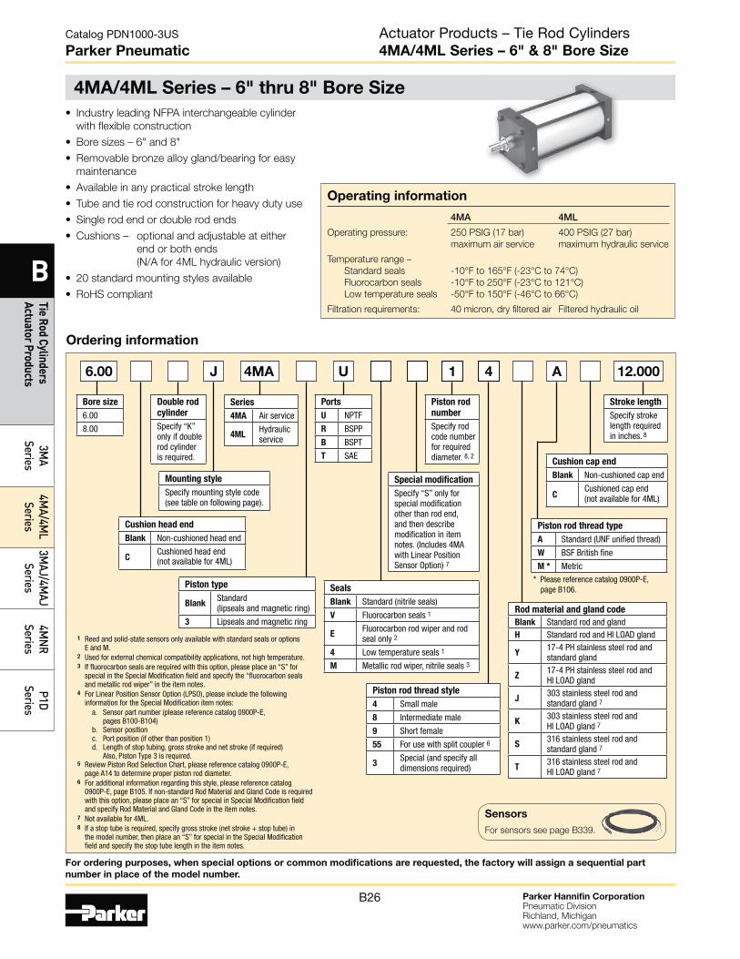
4MA/4ML Series – 6" thru 8" Bore Size
Operating information
4MA 4ML
Operating pressure: 250 PSIG (17 bar) 400 PSIG (27 bar)
maximum air service maximum hydraulic service
Temperature range –
Standard seals -10°F to 165°F (-23°C to 74°C)
Fluorocarbon seals -10°F to 250°F (-23°C to 121°C)
Low temperature seals -50°F to 150°F (-46°C to 66°C)
Filtration requirements: 40 micron, dry filtered air Filtered hydraulic oil
• Industry leading NFPA interchangeable cylinder
with flexible construction
• Bore sizes – 6" and 8"
• Removable bronze alloy gland/bearing for easy
maintenance
• Available in any practical stroke length
• Tube and tie rod construction for heavy duty use
• Single rod end or double rod ends
• Cushions – optional and adjustable at either
end or both ends
(N/A for 4ML hydraulic version)
• 20 standard mounting styles available
• RoHS compliant
Ordering information
J U 1 4 A 12.0006.00
Piston type
BlankStandard (lipseals and magnetic ring)
3 Lipseals and magnetic ring
Bore size
6.00
8.00
Stroke length
Specify stroke length required in inches. 8
Mounting style
Specify mounting style code (see table on following page).
Double rod
cylinder
Specify “K” only if double rod cylinder is required.
Piston rod
number
Specify rod code number for required diameter. 8, 2
Ports
U NPTF
R BSPP
B BSPT
T SAE
Cushion head end
Blank Non-cushioned head end
CCushioned head end (not available for 4ML)
Cushion cap end
Blank Non-cushioned cap end
CCushioned cap end (not available for 4ML)
Piston rod thread type
A Standard (UNF unified thread)
W BSF British fine
M * Metric
* Please reference catalog 0900P-E, page B106.
Rod material and gland code
Blank Standard rod and glandH Standard rod and HI LOAD gland
Y17-4 PH stainless steel rod and standard gland
Z17-4 PH stainless steel rod and HI LOAD gland
J303 stainless steel rod and standard gland 7
K303 stainless steel rod and HI LOAD gland 7
S316 stainless steel rod and standard gland 7
T316 stainless steel rod and HI LOAD gland 7
Piston rod thread style
4 Small male
8 Intermediate male
9 Short female
55 For use with split coupler 6
3Special (and specify all dimensions required)
Seals
Blank Standard (nitrile seals)
V Fluorocarbon seals 1
EFluorocarbon rod wiper and rod seal only 2
4 Low temperature seals 1
M Metallic rod wiper, nitrile seals 3
Series
4MA Air service
4MLHydraulic service
Special modification
Specify “S” only for special modification other than rod end, and then describe modification in item notes. (Includes 4MA with Linear Position Sensor Option) 7
1 Reed and solid-state sensors only available with standard seals or options E and M.2 Used for external chemical compatibility applications, not high temperature.3 If fluorocarbon seals are required with this option, please place an “S” for special in the Special Modification field and specify the “fluorocarbon seals and metallic rod wiper” in the item notes.4 For Linear Position Sensor Option (LPSO), please include the following information for the Special Modification item notes: a. Sensor part number (please reference catalog 0900P-E, pages B100-B104) b. Sensor position c. Port position (if other than position 1) d. Length of stop tubing, gross stroke and net stroke (if required) Also, Piston Type 3 is required.5 Review Piston Rod Selection Chart, please reference catalog 0900P-E, page A14 to determine proper piston rod diameter.6 For additional information regarding this style, please reference catalog 0900P-E, page B105. If non-standard Rod Material and Gland Code is required
with this option, please place an “S” for special in Special Modification field and specify Rod Material and Gland Code in the item notes.7 Not available for 4ML.8 If a stop tube is required, specify gross stroke (net stroke + stop tube) in the model number, then place an “S” for special in the Special Modification field and specify the stop tube length in the item notes.
4MA
Actuator Products – Tie Rod Cylinders4MA/4ML Series – 6" & 8" Bore Size
Sensors
For sensors see page B339.
For ordering purposes, when special options or common modifications are requested, the factory will assign a sequential part
number in place of the model number.

Parker Hannifin CorporationPneumatic DivisionRichland, Michiganwww.parker.com/pneumatics
B27
Catalog PDN1000-3US
Parker Pneumatic
B
Tie
Rod
Cylin
ders
Ac
tuat
or P
rodu
cts
3MA
Serie
s4M
A/4M
L Se
ries
3MAJ
/4M
AJ
Serie
s4M
NR
Serie
sP1
D Se
ries
Mounting style
NFPA mounting Description
Bore size
CB MS1 Side End Angle 6 - 8
BB MP1 Cap Fixed Clevis 6 - 8
BC MP2 Cap Detachable Clevis 6 - 8
BE MP4 Cap Detachable Eye 6
D MT1 Head Trunnion 6 - 8
DB MT2 Cap Trunnion 6 - 8
DD MT4 Intermediate Trunnion 6 - 8
JB ME3 Head Square 8
HB ME4 Cap Square 8
KT † MDX0 Double Rod End, No Mount 6 - 8
† Double rod end cylinders can be ordered with head mountings, i.e. KJ.
Mounting style
NFPA mounting Description
Bore size
T MX0 No Mount 6 - 8
J MF1 Head Rectangular Flange 6
H MF2 Cap Rectangular Flange 6
TB MX3 Tie Rods Extended
Head End
6 - 8
TC MX2 Tie Rods Extended
Cap End
6 - 8
TD MX1 Tie Rods Extended
Both Ends
6 - 8
TE MX5 Sleeve Nut 6 - 8
TEF MX5/MS4 Sleeve Nut with Side Tap 6 - 8
C MS2 Side Lug 6 - 8
F MS4 Side Tap 6 - 8
4MA/4ML Mounting Styles for 6" to 8" Bore
Actuator Products – Tie Rod Cylinders4MA/4ML Series – 6" & 8" Bore Size
Parker Hannifin CorporationPneumatic DivisionRichland, Michiganwww.parker.com/pneumatics
B28
Catalog PDN1000-3US
Parker Pneumatic
B
Tie Rod Cylinders Actuator Products
3MA
Series4M
A/4ML
Series3M
AJ/4MAJ
Series4M
NR
SeriesP1D
Series
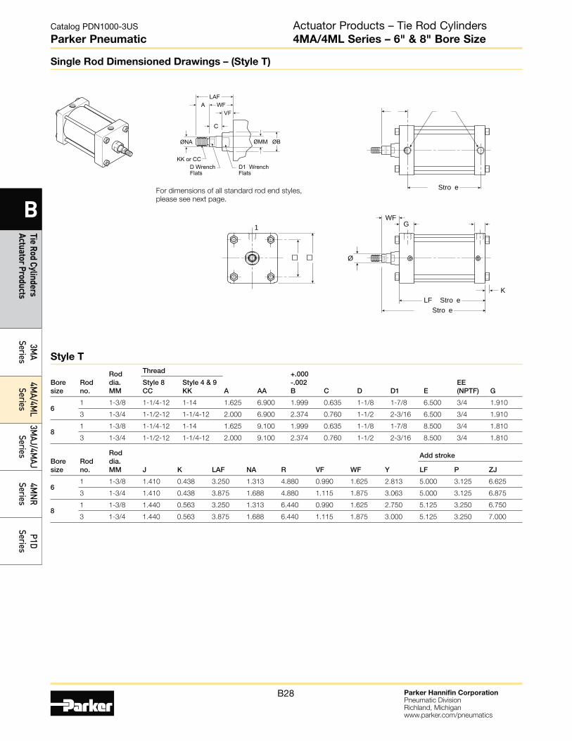
Single Rod Dimensioned Drawings – (Style T)
1
Stro e
Stro e
G
LF Stro eK
Ø
WF
For dimensions of all standard rod end styles,
please see next page.
KK or CC
ØNA
D WrenchFlats
D1 WrenchFlats
ØMM
WFVF
C
LAFA
ØB
Bore size
Rod no.
Rod dia. MM J K LAF NA R VF WF Y
Add stroke
LF P ZJ
6 1 1-3/8 1.410 0.438 3.250 1.313 4.880 0.990 1.625 2.813 5.000 3.125 6.625
3 1-3/4 1.410 0.438 3.875 1.688 4.880 1.115 1.875 3.063 5.000 3.125 6.875
8 1 1-3/8 1.440 0.563 3.250 1.313 6.440 0.990 1.625 2.750 5.125 3.250 6.750
3 1-3/4 1.440 0.563 3.875 1.688 6.440 1.115 1.875 3.000 5.125 3.250 7.000
Bore size
Rod no.
Rod dia. MM
Thread
A AA
+.000 -.002 B C D D1
E
EE (NPTF)
G
Style 8 CC
Style 4 & 9 KK
6 1 1-3/8 1-1/4-12 1-14 1.625 6.900 1.999 0.635 1-1/8 1-7/8 6.500 3/4 1.910
3 1-3/4 1-1/2-12 1-1/4-12 2.000 6.900 2.374 0.760 1-1/2 2-3/16 6.500 3/4 1.910
8 1 1-3/8 1-1/4-12 1-14 1.625 9.100 1.999 0.635 1-1/8 1-7/8 8.500 3/4 1.810
3 1-3/4 1-1/2-12 1-1/4-12 2.000 9.100 2.374 0.760 1-1/2 2-3/16 8.500 3/4 1.810
Style T
Actuator Products – Tie Rod Cylinders4MA/4ML Series – 6" & 8" Bore Size

Parker Hannifin CorporationPneumatic DivisionRichland, Michiganwww.parker.com/pneumatics
B29
Catalog PDN1000-3US
Parker Pneumatic
B
Tie
Rod
Cylin
ders
Ac
tuat
or P
rodu
cts
3MA
Serie
s4M
A/4M
L Se
ries
3MAJ
/4M
AJ
Serie
s4M
NR
Serie
sP1
D Se
ries
Bore size
Rod no.
Rod dia. MM
Thread
A AD AE AF AM
+.000 -.002 B C D D1 LAF NA VF WF WG
Style 8 CC
Style 4 & 9 KK
6 1 1-3/8 1-1/4-12 1-14 1.625 1.063 0.375 0.875 1.320 1.999 0.635 1-1/8 1-7/8 3.250 1.313 0.990 1.625 2.750
3 1-3/4 1-1/2-12 1-1/4-12 2.000 1.313 0.500 1.125 1.700 2.374 0.760 1-1/2 2-3/16 3.875 1.688 1.115 1.875 3.125
8 1 1-3/8 1-1/4-12 1-14 1.625 1.063 0.375 0.875 1.320 1.999 0.635 1-1/8 1-7/8 3.250 1.313 0.990 1.625 2.750
3 1-3/4 1-1/2-12 1-1/4-12 2.000 1.313 0.500 1.125 1.700 2.374 0.760 1-1/2 2-3/16 3.875 1.688 1.115 1.875 3.125
KK
D wrench flats
WF
VF
C
A
KKD wrench flats D1 wrench flats
WF
VF
C
LAF
A
CCD wrench flats D1 wrench flats
WF
VF
C
LAF
A
D1 wrench flats D1 wrench flats
Groove has 1/16"internal radii at corners
VF
VSØ1/16
Ø A
WGAD
AØAF
ØNA ØBØ ØBØ
ØNA ØBØ ØNA ØBØ
Rod End Dimensions
4MA Rod End Dimensions
Thread Style 4(NFPA Style SM)
Small Male
Thread Style 8(NFPA Style IM)
Intermediate Male
Thread Style 9(NFPA Style SF)
Short Female
Thread Style 55For use with Split Coupler
(please reference catalog 0900P-E, page B105 for
more information)
Thread Style 3 - “Special Thread”Special threads, rod extensions, rod eyes, blanks, etc. are also available.
To order, specify “Style 3” and give desired dimensions for KK or CC, A and W or WF.
If otherwise special, please supply dimensioned sketch.
Actuator Products – Tie Rod Cylinders4MA/4ML Series – 6" & 8" Bore Size
Parker Hannifin CorporationPneumatic DivisionRichland, Michiganwww.parker.com/pneumatics
B30
Catalog PDN1000-3US
Parker Pneumatic
B
Tie Rod Cylinders Actuator Products
3MA
Series4M
A/4ML
Series3M
AJ/4MAJ
Series4M
NR
SeriesP1D
Series
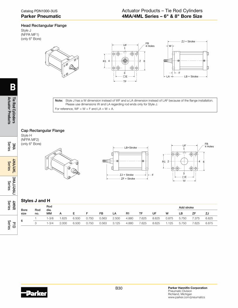
Head Rectangular FlangeStyle J
(NFPA MF1)
(only 6" Bore)
Cap Rectangular FlangeStyle H
(NFPA MF2)
(only 6" Bore)
1
2
3
4
TF
UF
R1
FB4 Holes
ZJ + Stroke
LB + StrokeF
LA
W
E
E
1
4
3
2
TF
UF
R1
FB4 Holes
ZF + StrokeZJ + Stroke
LB+Stroke
F
E
E
Boresize
Rodno.
Roddia.MM A E F FB LA R1 TF UF W
Add stroke
LB ZF ZJ
61 1-3/8 1.625 6.500 0.750 0.563 2.500 4.880 7.625 8.625 0.875 5.750 7.375 6.625
3 1-3/4 2.000 6.500 0.750 0.563 3.125 4.880 7.625 8.625 1.125 5.750 7.625 6.875
Note: Style J has a W dimension instead of WF and a LA dimension instead of LAF because of the flange installation.
Please use dimensions W and LA regarding rod ends only for Style J.
For reference, WF = W + F and LA = W + A.
Styles J and H
Actuator Products – Tie Rod Cylinders4MA/4ML Series – 6" & 8" Bore Size
Parker Hannifin CorporationPneumatic DivisionRichland, Michiganwww.parker.com/pneumatics
B31
Catalog PDN1000-3US
Parker Pneumatic
B
Tie
Rod
Cylin
ders
Ac
tuat
or P
rodu
cts
3MA
Serie
s4M
A/4M
L Se
ries
3MAJ
/4M
AJ
Serie
s4M
NR
Serie
sP1
D Se
ries
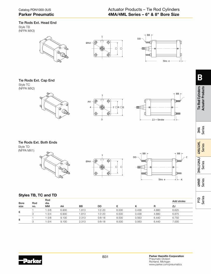
Tie Rods Ext. Head EndStyle TB
(NFPA MX3)
Tie Rods Ext. Cap EndStyle TC
(NFPA MX2)
1
ØAA
Stro e K
BBDD
1
2
AA
3
4
ZJ + Stroke
ER
BB
Tie Rods Ext. Both EndsStyle TD
(NFPA MX1)
1
ØAA
Stro e K
BBDD DD
BB
Bore size
Rod no.
Rod dia. MM AA BB DD E K R
Add stroke
ZJ
6 1 1-3/8 6.900 1.813 1/2-20 6.500 0.438 4.880 6.625
3 1-3/4 6.900 1.813 1/2-20 6.500 0.438 4.880 6.875
8 1 1-3/8 9.100 2.313 5/8-18 8.500 0.563 6.440 6.750
3 1-3/4 9.100 2.313 5/8-18 8.500 0.563 6.440 7.000
Styles TB, TC and TD
Actuator Products – Tie Rod Cylinders4MA/4ML Series – 6" & 8" Bore Size
Parker Hannifin CorporationPneumatic DivisionRichland, Michiganwww.parker.com/pneumatics
B32
Catalog PDN1000-3US
Parker Pneumatic
B
Tie Rod Cylinders Actuator Products
3MA
Series4M
A/4ML
Series3M
AJ/4MAJ
Series4M
NR
SeriesP1D
Series
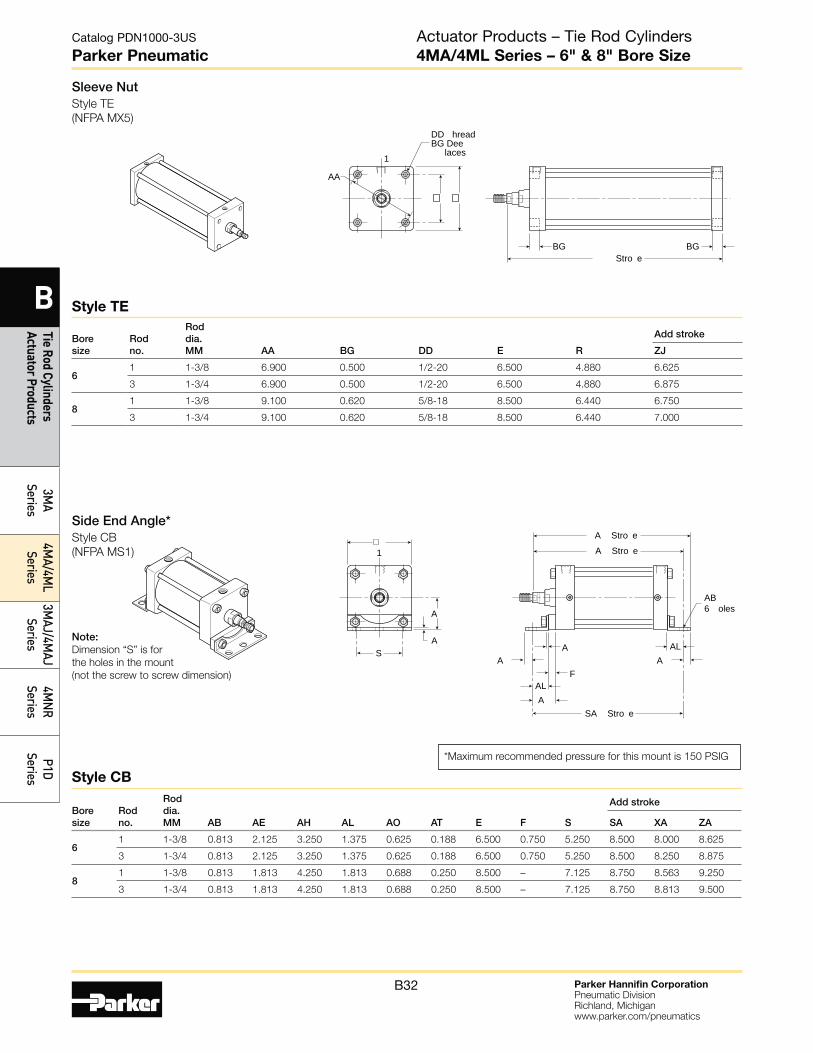
Sleeve NutStyle TE
(NFPA MX5)
1
AA
Stro eBG BG
DD hreadBG Dee laces
Bore size
Rod no.
Rod dia. MM AA BG DD E R
Add stroke
ZJ
6 1 1-3/8 6.900 0.500 1/2-20 6.500 4.880 6.625
3 1-3/4 6.900 0.500 1/2-20 6.500 4.880 6.875
8 1 1-3/8 9.100 0.620 5/8-18 8.500 6.440 6.750
3 1-3/4 9.100 0.620 5/8-18 8.500 6.440 7.000
Bore size
Rod no.
Rod dia. MM AB AE AH AL AO AT E F S
Add stroke
SA XA ZA
6 1 1-3/8 0.813 2.125 3.250 1.375 0.625 0.188 6.500 0.750 5.250 8.500 8.000 8.625
3 1-3/4 0.813 2.125 3.250 1.375 0.625 0.188 6.500 0.750 5.250 8.500 8.250 8.875
8 1 1-3/8 0.813 1.813 4.250 1.813 0.688 0.250 8.500 – 7.125 8.750 8.563 9.250
3 1-3/4 0.813 1.813 4.250 1.813 0.688 0.250 8.500 – 7.125 8.750 8.813 9.500
Style TE
Style CB
Side End Angle*Style CB
(NFPA MS1)
Note: Dimension “S” is for
the holes in the mount
(not the screw to screw dimension)
*Maximum recommended pressure for this mount is 150 PSIG
AB6 olesA
1
A Stro e
SA Stro e
A Stro e
AAL
A AF
A ALS
A
Actuator Products – Tie Rod Cylinders4MA/4ML Series – 6" & 8" Bore Size

Parker Hannifin CorporationPneumatic DivisionRichland, Michiganwww.parker.com/pneumatics
B33
Catalog PDN1000-3US
Parker Pneumatic
B
Tie
Rod
Cylin
ders
Ac
tuat
or P
rodu
cts
3MA
Serie
s4M
A/4M
L Se
ries
3MAJ
/4M
AJ
Serie
s4M
NR
Serie
sP1
D Se
ries
Side LugStyle C
(NFPA MS2)
Side TapStyle F
(NFPA MS4)
L
SB oles
1
Stro eSS Stro e
SWSWS
SWSWSWSW
SS
S
N hread ND Dee a ed o ntin oles
1
Stro eSN Stro e
DD
N
±
Bore size
Rod no.
Rod dia. MM E ND NT
+/-.003 TH TN XT
Add stroke
SN ZJ
6 1 1-3/8 6.500 1.125 3/4-10 3.243 3.250 2.813 3.125 6.625
3 1-3/4 6.500 1.125 3/4-10 3.243 3.250 3.063 3.125 6.875
8 1 1-3/8 8.500 1.125 3/4-10 4.243 4.500 2.813 3.250 6.750
3 1-3/4 8.500 1.125 3/4-10 4.243 4.500 3.063 3.250 7.000
Bore size
Rod no.
Rod dia. MM E
+/-.003 LH SB ST SW TS US XS
Add stroke
SS ZJ
61 1-3/8 6.500 3.243 0.813 1.000 0.688 7.875 9.250 2.313 3.625 6.625
3 1-3/4 6.500 3.243 0.813 1.000 0.688 7.875 9.250 2.563 3.625 6.875
8 1 1-3/8 8.500 4.243 0.813 1.000 0.688 9.875 11.250 2.313 3.750 6.750
3 1-3/4 8.500 4.243 0.813 1.000 0.688 9.875 11.250 2.563 3.750 7.000
Style C
Style F
Actuator Products – Tie Rod Cylinders4MA/4ML Series – 6" & 8" Bore Size

Parker Hannifin CorporationPneumatic DivisionRichland, Michiganwww.parker.com/pneumatics
B34
Catalog PDN1000-3US
Parker Pneumatic
B
Tie Rod Cylinders Actuator Products
3MA
Series4M
A/4ML
Series3M
AJ/4MAJ
Series4M
NR
SeriesP1D
Series
Cap Detachable ClevisStyle BC
(NFPA MP2)
Cap Detachable EyeStyle BE
(NFPA MP4)
(only 6" Bore)
1
D Stro eD Stro e
FCW
CBCW
L1
1
ØCD
1
D1 Stro eD Stro e
FCBL1
ØCD1
Cap Fixed ClevisStyle BB
(NFPA MP1)
1
C Stro eC Stro e
FCW
CBCW
L
L
ØCD
Note: For maximum swivel angle of BB mount with rear mounting plate, please
reference catalog 0900P-E, cylinder accessories on page B108.
Bore size
Rod no.
Rod dia. MM CB
+.002 +.004 CD1 E F L1 MR2
Add stroke
XD ZD1
6 1 1-3/8 1.500 1.000 6.500 0.750 1.500 1.125 8.875 10.000
3 1-3/4 1.500 1.000 6.500 0.750 1.500 1.125 9.125 10.250
Bore size
Rod no.
Rod dia. MM CB
+.000 -.002 CD CW E F L LR L1 MR MR1
Add stroke
XC XD ZC ZD
6 1 1- 3/8 1.500 1.001 0.750 6.500 0.750 0.750 1.250 1.500 1.125 1.000 8.125 8.875 9.250 9.875
3 1-3/4 1.500 1.001 0.750 6.500 0.750 0.750 1.250 1.500 1.125 1.000 8.375 9.125 9.500 10.125
8 1 1-3/8 1.500 1.001 0.750 8.500 0.750 0.750 1.250 1.500 1.125 1.000 8.250 9.000 9.375 10.000
3 1-3/4 1.500 1.001 0.750 8.500 0.750 0.750 1.250 1.500 1.125 1.000 8.500 9.250 9.625 10.250
Styles BB and BC
Style BE
Actuator Products – Tie Rod Cylinders4MA/4ML Series – 6" & 8" Bore Size
Parker Hannifin CorporationPneumatic DivisionRichland, Michiganwww.parker.com/pneumatics
B35
Catalog PDN1000-3US
Parker Pneumatic
B
Tie
Rod
Cylin
ders
Ac
tuat
or P
rodu
cts
3MA
Serie
s4M
A/4M
L Se
ries
3MAJ
/4M
AJ
Serie
s4M
NR
Serie
sP1
D Se
ries
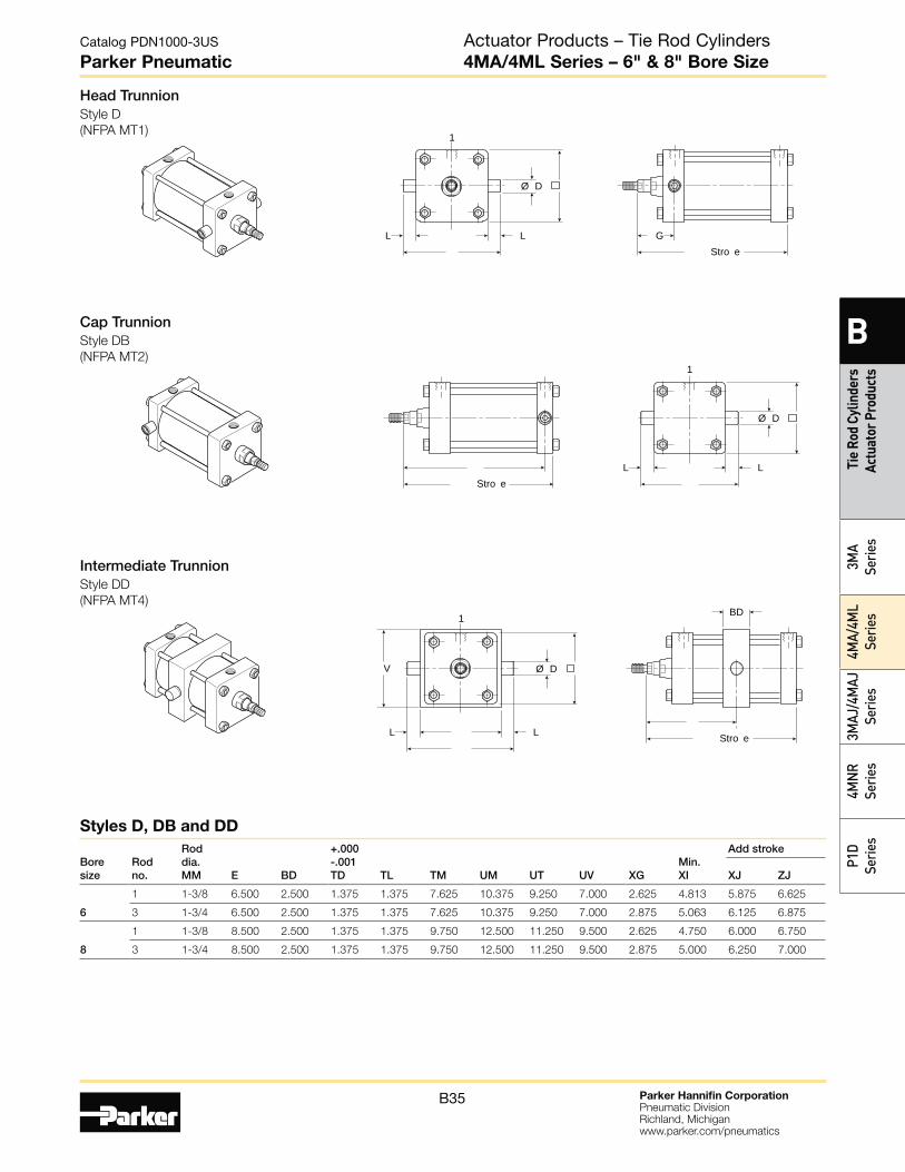
Cap TrunnionStyle DB
(NFPA MT2)
Head TrunnionStyle D
(NFPA MT1) 1
L L Stro e
G
Ø D
1
L L Stro e
Ø D
Intermediate TrunnionStyle DD
(NFPA MT4)
L L
1
Stro e
BD
V Ø D
Bore size
Rod no.
Rod dia. MM E BD
+.000 -.001 TD TL TM UM UT UV XG
Min. XI
Add stroke
XJ ZJ
6
1 1-3/8 6.500 2.500 1.375 1.375 7.625 10.375 9.250 7.000 2.625 4.813 5.875 6.625
3 1-3/4 6.500 2.500 1.375 1.375 7.625 10.375 9.250 7.000 2.875 5.063 6.125 6.875
8
1 1-3/8 8.500 2.500 1.375 1.375 9.750 12.500 11.250 9.500 2.625 4.750 6.000 6.750
3 1-3/4 8.500 2.500 1.375 1.375 9.750 12.500 11.250 9.500 2.875 5.000 6.250 7.000
Styles D, DB and DD
Actuator Products – Tie Rod Cylinders4MA/4ML Series – 6" & 8" Bore Size
Parker Hannifin CorporationPneumatic DivisionRichland, Michiganwww.parker.com/pneumatics
B36
Catalog PDN1000-3US
Parker Pneumatic
B
Tie Rod Cylinders Actuator Products
3MA
Series4M
A/4ML
Series3M
AJ/4MAJ
Series4M
NR
SeriesP1D
Series
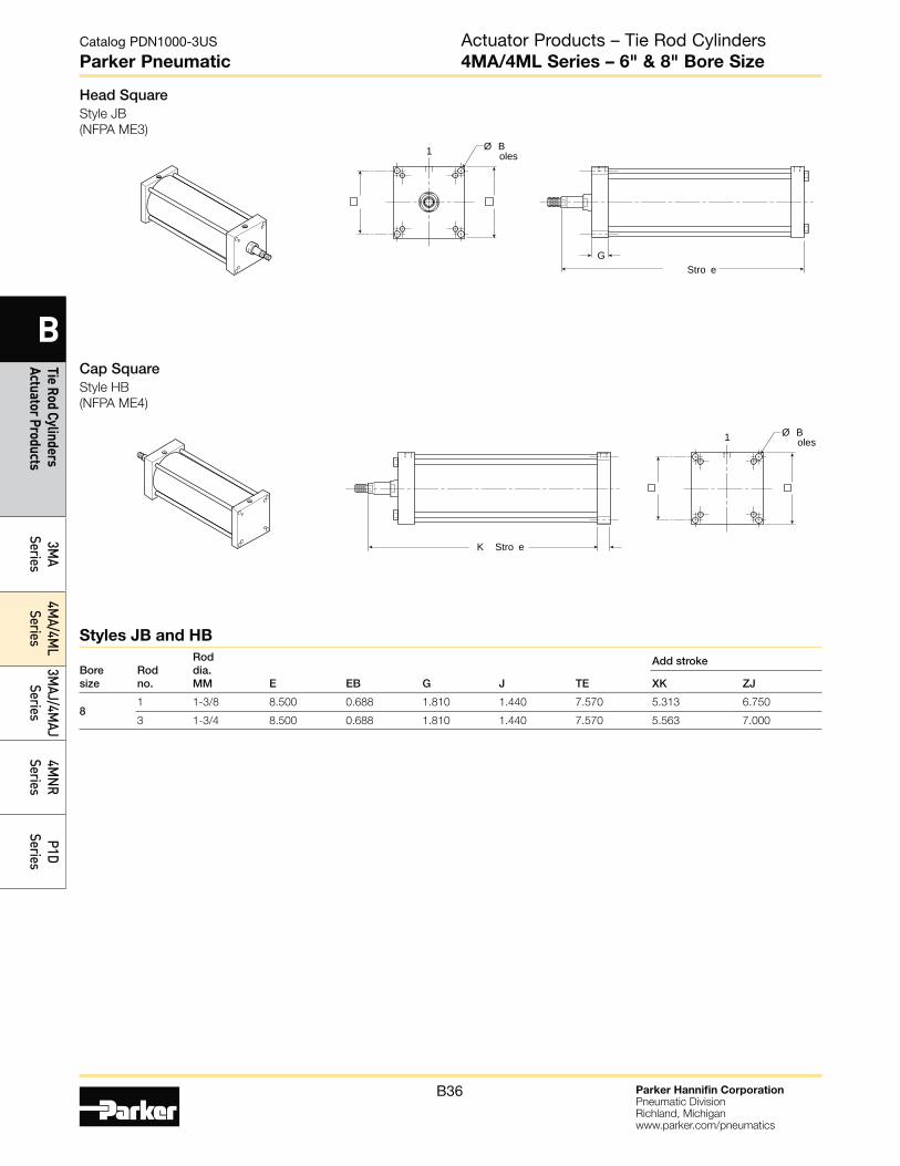
Head SquareStyle JB
(NFPA ME3)
1
Stro eG
Ø B oles
Cap SquareStyle HB
(NFPA ME4)
K Stro e
1 Ø B oles
Bore size
Rod no.
Rod dia. MM E EB G J TE
Add stroke
XK ZJ
8 1 1-3/8 8.500 0.688 1.810 1.440 7.570 5.313 6.750
3 1-3/4 8.500 0.688 1.810 1.440 7.570 5.563 7.000
Styles JB and HB
Actuator Products – Tie Rod Cylinders4MA/4ML Series – 6" & 8" Bore Size

Parker Hannifin CorporationPneumatic DivisionRichland, Michiganwww.parker.com/pneumatics
B37
Catalog PDN1000-3US
Parker Pneumatic
B
Tie
Rod
Cylin
ders
Ac
tuat
or P
rodu
cts
3MA
Serie
s4M
A/4M
L Se
ries
3MAJ
/4M
AJ
Serie
s4M
NR
Serie
sP1
D Se
ries
** Spacer plate not used for 4” bore or double rod cylinders
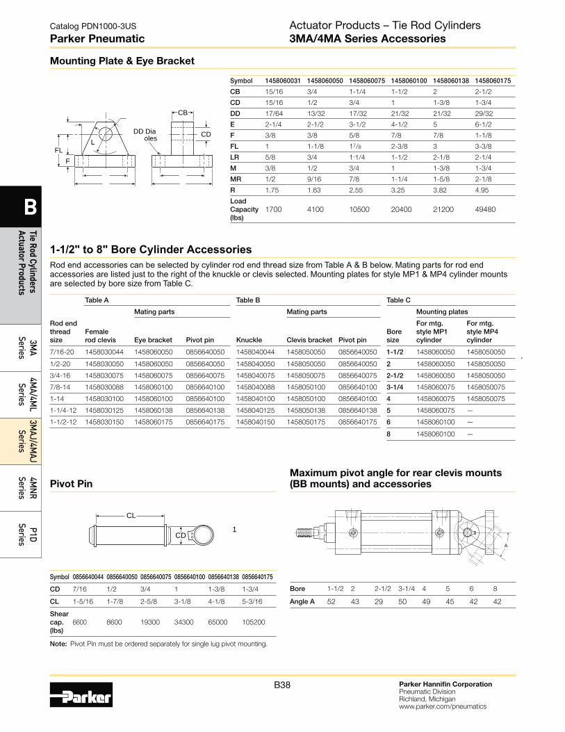
Mounting Kits and Accessories
Boresize
J (MF1) H (MF2) BB (MP1) BC (MP2) BE (MP4) CB (MS1) C (MS2) G (MS7)
Kit fastener torqueunits
Headrectangularflange
Caprectangularflange
Cap fixedclevis
Capdetachable clevis
Capdetachable eye
Side endangles
Side lug(3MA only) Side end lug
Kit number Kit number Kit number Kit number Kit number Kit number Kit number Kit number inch-lbs N-m
1-1/2 L079700150 L079700150 L079710150 L079730150 L079720150 L079740150 L079830150 L079750150 32-36 3.6-4.1
2 L079700200 L079700200 L079710200 L079730200 L079720200 L079740200 L079830200 L079750200 72-82 8-9
2-1/2 L079700250 L079700250 L079710250 L079730250 L079720250 L079740250 L079830250 L079750250 72-82 8-9
3-1/4 L079700325 L079700325 L079710325 L079730325 L079720325 L079740325 L079830325 L079750325 216-228 24-25.3
4 L079700400 L079700400 L079710400 L079730400 L079720400 L079740400 L079830400 L079750400 216-228 24-25.3
5 L079700500 L079700500 L079710500 L079730500 N/A L079740500 L079830500 N/A 360-372 41-42
Symbol 1458050044 1458050050 1458050075 1458050100 1458050138 1458050175
CB 15/32 3/4 1-1/4 1-1/2 2 2-1/2
CD 7/16 1/2 3/4 1 1-3/8 1-3/4
CW 3/8 1/2 5/8 3/4 1 1-1/4
DD 17/64 13/32 17/32 21/32 21/32 29/32
E 2-1/4 3-1/2 5 6-1/2 7-1/2 9-1/2
F 3/8 1/2 5/8 3/4 7/8 7/8
FL 1 1-1/2 1-7/8 2-1/4 3 3-5/8
LR 5/8 3/4 1-3/16 1-1/2 2 2-3/4
M 3/8 1/2 3/4 1 1-3/8 1-3/4
MR 1/2 5/8 29/32 1-1/4 1-21/32 2-7/32
R 1.75 2.55 3.82 4.95 5.73 7.50
Loadcapacity(lbs)
3600 7300 14000 19200 36900 34000
FLF
LCD
CW CWCB
DD Dia oles
Clevis Bracket
CD
CBCA
CD
CD
CDAF ll hread
KK hread
Symbol 1458040044 1458040050 1458040075 1458040088 1458040100 1458040125 1458040150
A 3/4 3/4 1-1/8 1-1/8 1-5/8 2 2-1/4
CA 1-1/2 1-1/2 2-1/16 2-3/8 2-13/16 3-7/16 4
CB 3/4 3/4 1-1/4 1-1/2 1-1/2 2 2-1/2
CD 1/2 1/2 3/4 1 1 1-3/8 1-3/4
ER 23/32 23/32 1-1/16 1-7/16 1-7/16 1-31/32 2-1/2
KK 7/16-20 1/2-20 3/4-16 7/8-14 1-14 1-1/4-12 1-1/2-12
Loadcapacity(lbs)
5000 5700 12100 13000 21700 33500 45000
Rod Eye Knuckle
CD
CW CWCB
AC
KK hread
Symbol 1458030044 1458030050 1458030075 1458030088 1458030100 1458030125 1458030150
A 3/4 3/4 1-1/8 1-5/8 1-5/8 2 2-1/4
CB 3/4 3/4 1-1/4 1-1/2 1-1/2 2 2-1/2
CD 1/2 1/2 3/4 1 1 1-3/8 1-3/4
C E 1-1/2 1-1/2 2-1/8 2-15/16 2-15/16 3-3/4 4-1/2
CW 1/2 1/2 5/8 3/4 3/4 1 1-1/4
ER 1/2 1/2 3/4 1 1 1-3/8 1-3/4
KK 7/16-20 1/2-20 3/4-16 7/8-14 1-14 1-1/4-12 1-1/2-12
Loadcapacity(lbs)
4250 4900 11200 18800 19500 33500 45600
Female Rod Clevis
Actuator Products – Tie Rod Cylinders3MA/4MA Series Accessories
Parker Hannifin CorporationPneumatic DivisionRichland, Michiganwww.parker.com/pneumatics
B38
Catalog PDN1000-3US
Parker Pneumatic
B
Tie Rod Cylinders Actuator Products
3MA
Series4M
A/4ML
Series3M
AJ/4MAJ
Series4M
NR
SeriesP1D
Series
Symbol 1458060031 1458060050 1458060075 1458060100 1458060138 1458060175
CB 15/16 3/4 1-1/4 1-1/2 2 2-1/2
CD 15/16 1/2 3/4 1 1-3/8 1-3/4
DD 17/64 13/32 17/32 21/32 21/32 29/32
E 2-1/4 2-1/2 3-1/2 4-1/2 5 6-1/2
F 3/8 3/8 5/8 7/8 7/8 1-1/8
FL 1 1-1/8 17/8 2-3/8 3 3-3/8
LR 5/8 3/4 1-1/4 1-1/2 2-1/8 2-1/4
M 3/8 1/2 3/4 1 1-3/8 1-3/4
MR 1/2 9/16 7/8 1-1/4 1-5/8 2-1/8
R 1.75 1.63 2.55 3.25 3.82 4.95
LoadCapacity(lbs)
1700 4100 10500 20400 21200 49480
LFL
F
CD
CB
DD Dia oles
Mounting Plate & Eye Bracket
Rod endthreadsize
Table A Table B Table C
Femalerod clevis
Mating parts
Knuckle
Mating parts
Boresize
Mounting plates
Eye bracket Pivot pin Clevis bracket Pivot pin
For mtg. style MP1cylinder
For mtg.style MP4cylinder
7/16-20 1458030044 1458060050 0856640050 1458040044 1458050050 0856640050 1-1/2 1458060050 1458050050
1/2-20 1458030050 1458060050 0856640050 1458040050 1458050050 0856640050 2 1458060050 1458050050
3/4-16 1458030075 1458060075 0856640075 1458040075 1458050075 0856640075 2-1/2 1458060050 1458050050
7/8-14 1458030088 1458060100 0856640100 1458040088 1458050100 0856640100 3-1/4 1458060075 1458050075
1-14 1458030100 1458060100 0856640100 1458040100 1458050100 0856640100 4 1458060075 1458050075
1-1/4-12 1458030125 1458060138 0856640138 1458040125 1458050138 0856640138 5 1458060075 —
1-1/2-12 1458030150 1458060175 0856640175 1458040150 1458050175 0856640175 6 1458060100 —
8 1458060100 —
1-1/2" to 8" Bore Cylinder AccessoriesRod end accessories can be selected by cylinder rod end thread size from Table A & B below. Mating parts for rod end accessories are listed just to the right of the knuckle or clevis selected. Mounting plates for style MP1 & MP4 cylinder mounts are selected by bore size from Table C.
Symbol 0856640044 0856640050 0856640075 0856640100 0856640138 0856640175
CD 7/16 1/2 3/4 1 1-3/8 1-3/4
CL 1-5/16 1-7/8 2-5/8 3-1/8 4-1/8 5-3/16
Shear cap. (lbs)
6600 8600 19300 34300 65000 105200
A
CD1
CL
Note: Pivot Pin must be ordered separately for single lug pivot mounting.
Pivot Pin
Bore 1-1/2 2 2-1/2 3-1/4 4 5 6 8
Angle A 52 43 29 50 49 45 42 42
Maximum pivot angle for rear clevis mounts (BB mounts) and accessories
Actuator Products – Tie Rod Cylinders3MA/4MA Series Accessories
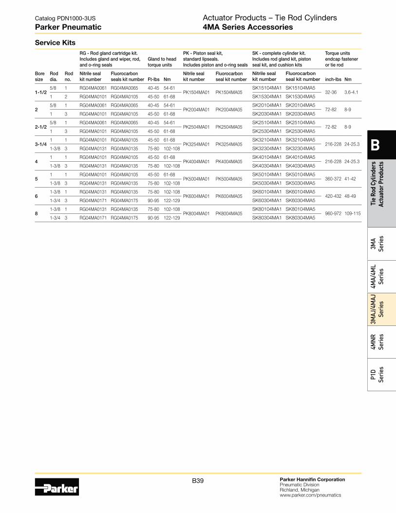
Parker Hannifin CorporationPneumatic DivisionRichland, Michiganwww.parker.com/pneumatics
B39
Catalog PDN1000-3US
Parker Pneumatic
B
Tie
Rod
Cylin
ders
Ac
tuat
or P
rodu
cts
3MA
Serie
s4M
A/4M
L Se
ries
3MAJ
/4M
AJ
Serie
s4M
NR
Serie
sP1
D Se
ries
Actuator Products – Tie Rod Cylinders4MA Series Accessories
Service Kits
Bore size
Rod dia.
Rod no.
RG - Rod gland cartridge kit. Includes gland and wiper, rod, and o-ring seals
Gland to head torque units
PK - Piston seal kit, standard lipseals. Includes piston and o-ring seals
SK - complete cylinder kit. Includes rod gland kit, piston seal kit, and cushion kits
Torque units endcap fastener or tie rod
Nitrile seal kit number
Fluorocarbon seals kit number Ft-lbs Nm
Nitrile seal kit number
Fluorocarbon seal kit number
Nitrile seal kit number
Fluorocarbon seal kit number inch-lbs Nm
1-1/2 5/8 1 RG04MA0061 RG04MA0065 40-45 54-61
PK1504MA01 PK1504MA05SK15104MA1 SK15104MA5
32-36 3.6-4.11 2 RG04MA0101 RG04MA0105 45-50 61-68 SK15304MA1 SK15304MA5
2 5/8 1 RG04MA0061 RG04MA0065 40-45 54-61
PK2004MA01 PK2004MA05SK20104MA1 SK20104MA5
72-82 8-91 3 RG04MA0101 RG04MA0105 45-50 61-68 SK20304MA1 SK20304MA5
2-1/2 5/8 1 RG04MA0061 RG04MA0065 40-45 54-61
PK2504MA01 PK2504MA05SK25104MA1 SK25104MA5
72-82 8-91 3 RG04MA0101 RG04MA0105 45-50 61-68 SK25304MA1 SK25304MA5
3-1/4 1 1 RG04MA0101 RG04MA0105 45-50 61-68
PK3254MA01 PK3254MA05SK32104MA1 SK32104MA5
216-228 24-25.31-3/8 3 RG04MA0131 RG04MA0135 75-80 102-108 SK32304MA1 SK32304MA5
4 1 1 RG04MA0101 RG04MA0105 45-50 61-68
PK4004MA01 PK4004MA05SK40104MA1 SK40104MA5
216-228 24-25.31-3/8 3 RG04MA0131 RG04MA0135 75-80 102-108 SK40304MA1 SK40304MA5
5 1 1 RG04MA0101 RG04MA0105 45-50 61-68
PK5004MA01 PK5004MA05 SK50104MA1 SK50104MA5
360-372 41-421-3/8 3 RG04MA0131 RG04MA0135 75-80 102-108 SK50304MA1 SK50304MA5
6 1-3/8 1 RG04MA0131 RG04MA0135 75-80 102-108
PK6004MA01 PK6004MA05SK60104MA1 SK60104MA5
420-432 48-491-3/4 3 RG04MA0171 RG04MA0175 90-95 122-129 SK60304MA1 SK60304MA5
8 1-3/8 1 RG04MA0131 RG04MA0135 75-80 102-108
PK8004MA01 PK8004MA05SK80104MA1 SK80104MA5
960-972 109-1151-3/4 3 RG04MA0171 RG04MA0175 90-95 122-129 SK80304MA1 SK80304MA5
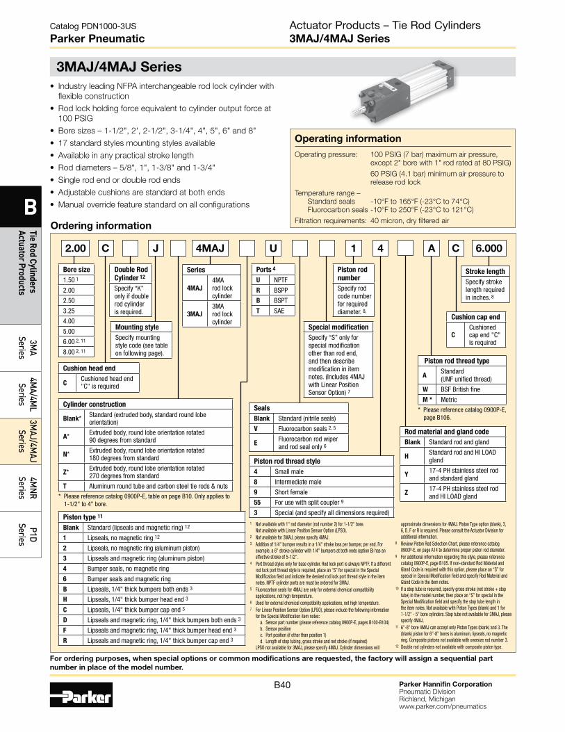
Parker Hannifin CorporationPneumatic DivisionRichland, Michiganwww.parker.com/pneumatics
B40
Catalog PDN1000-3US
Parker Pneumatic
B
Tie Rod Cylinders Actuator Products
3MA
Series4M
A/4ML
Series3M
AJ/4MAJ
Series4M
NR
SeriesP1D
Series
3MAJ/4MAJ Series
Actuator Products – Tie Rod Cylinders3MAJ/4MAJ Series
Operating information
Operating pressure: 100 PSIG (7 bar) maximum air pressure,
except 2" bore with 1" rod rated at 80 PSIG)
60 PSIG (4.1 bar) minimum air pressure to
release rod lock
Temperature range –
Standard seals -10°F to 165°F (-23°C to 74°C)
Fluorocarbon seals -10°F to 250°F (-23°C to 121°C)
Filtration requirements: 40 micron, dry filtered air
• Industry leading NFPA interchangeable rod lock cylinder with
flexible construction
• Rod lock holding force equivalent to cylinder output force at
100 PSIG
• Bore sizes – 1-1/2", 2', 2-1/2", 3-1/4", 4", 5", 6" and 8"
• 17 standard styles mounting styles available
• Available in any practical stroke length
• Rod diameters – 5/8", 1", 1-3/8" and 1-3/4"
• Single rod end or double rod ends
• Adjustable cushions are standard at both ends
• Manual override feature standard on all configurations
Ordering information
JC U 1 4 A 6.0002.00
Bore size
1.50 1
2.00
2.50
3.25
4.00
5.00
6.00 2, 11
8.00 2, 11
Stroke length
Specify stroke length required in inches. 8
Mounting style
Specify mounting style code (see table on following page).
Double Rod
Cylinder 12
Specify “K” only if double rod cylinder is required.
Piston rod
number
Specify rod code number for required diameter. 8,
Ports 4
U NPTF
R BSPP
B BSPT
T SAE
Cushion head end
CCushioned head end "C" is required
Cushion cap end
CCushioned cap end "C" is required
Piston rod thread type
AStandard (UNF unified thread)
W BSF British fine
M * Metric
* Please reference catalog 0900P-E, page B106.
Rod material and gland code
Blank Standard rod and gland
HStandard rod and HI LOAD gland
Y17-4 PH stainless steel rod and standard gland
Z17-4 PH stainless steel rod and HI LOAD gland
Piston rod thread style
4 Small male
8 Intermediate male
9 Short female
55 For use with split coupler 9
3 Special (and specify all dimensions required)
Seals
Blank Standard (nitrile seals)
V Fluorocarbon seals 2, 5
EFluorocarbon rod wiper and rod seal only 6
Series
4MAJ
4MA rod lock cylinder
3MAJ
3MA rod lock cylinder
Special modification
Specify “S” only for special modification other than rod end, and then describe modification in item notes. (Includes 4MAJ with Linear Position Sensor Option) 7
4MAJ C
Cylinder construction
Blank* Standard (extruded body, standard round lobe orientation)
A* Extruded body, round lobe orientation rotated 90 degrees from standard
N* Extruded body, round lobe orientation rotated 180 degrees from standard
Z* Extruded body, round lobe orientation rotated 270 degrees from standard
T Aluminum round tube and carbon steel tie rods & nuts
* Please reference catalog 0900P-E, table on page B10. Only applies to 1-1/2" to 4" bore.
Piston type 11
Blank Standard (lipseals and magnetic ring) 12
1 Lipseals, no magnetic ring 12
2 Lipseals, no magnetic ring (aluminum piston)
3 Lipseals and magnetic ring (aluminum piston)
4 Bumper seals, no magnetic ring
6 Bumper seals and magnetic ring
B Lipseals, 1/4" thick bumpers both ends 3
H Lipseals, 1/4" thick bumper head end 3
C Lipseals, 1/4" thick bumper cap end 3
D Lipseals and magnetic ring, 1/4" thick bumpers both ends 3
F Lipseals and magnetic ring, 1/4" thick bumper head end 3
R Lipseals and magnetic ring, 1/4" thick bumper cap end 3
1 Not available with 1" rod diameter (rod number 2) for 1-1/2" bore.Not available with Linear Position Sensor Option (LPSO).
2 Not available for 3MAJ, please specify 4MAJ.3 Addition of 1/4" bumper results in a 1/4" stroke loss per bumper, per end. For
example, a 6" stroke cylinder with 1/4" bumpers at both ends (option B) has an effective stroke of 5-1/2".
4 Port thread styles only for base cylinder. Rod lock port is always NPTF. If a different rod lock port thread style is required, place an “S” for special in the Special Modification field and indicate the desired rod lock port thread style in the item notes. NPTF cylinder ports are must be ordered for 3MAJ.
5 Fluorocarbon seals for 4MAJ are only for external chemical compatibility applications, not high temperature.
6 Used for external chemical compatibility applications, not high temperature.7 For Linear Position Sensor Option (LPSO), please include the following information
for the Special Modification item notes: a. Sensor part number (please reference catalog 0900P-E, pages B100-B104) b. Sensor position c. Port position (if other than position 1) d. Length of stop tubing, gross stroke and net stroke (if required) LPSO not available for 3MAJ, please specify 4MAJ. Cylinder dimensions will
approximate dimensions for 4MAJ. Piston Type option (blank), 3, 6, D, F or R is required. Please consult the Actuator Division for additional information.
8 Review Piston Rod Selection Chart, please reference catalog 0900P-E, on page A14 to determine proper piston rod diameter.
9 For additional information regarding this style, please reference catalog 0900P-E, page B105. If non-standard Rod Material and Gland Code is required with this option, please place an “S” for special in Special Modification field and specify Rod Material and Gland Code in the item notes.
10 If a stop tube is required, specify gross stroke (net stroke + stop tube) in the model number, then place an “S” for special in the Special Modification field and specify the stop tube length in the item notes. Not available with Piston Types (blank) and 1 for 1-1/2" - 5" bore cylinders. Stop tube not available for 3MAJ, please specify 4MAJ.
11 6"-8" bore 4MAJ can accept only Piston Types (blank) and 3. The (blank) piston for 6"-8" bores is aluminum, lipseals, no magnetic ring. Composite pistons not available with oversize rod number 3.
12 Double rod cylinders not available with composite piston type.
For ordering purposes, when special options or common modifications are requested, the factory will assign a sequential part
number in place of the model number.

Parker Hannifin CorporationPneumatic DivisionRichland, Michiganwww.parker.com/pneumatics
B41
Catalog PDN1000-3US
Parker Pneumatic
B
Tie
Rod
Cylin
ders
Ac
tuat
or P
rodu
cts
3MA
Serie
s4M
A/4M
L Se
ries
3MAJ
/4M
AJ
Serie
s4M
NR
Serie
sP1
D Se
ries
Mounting style
NFPA mounting Description
Bore size
BB MP1 Cap Fixed Clevis 1-1/2 - 8
BC MP2 Cap Detachable Clevis 1-1/2 - 8
BE MP4 Cap Detachable Eye 1-1/2 - 6
D MT1 Head Trunnion 1-1/2 - 8
DB MT2 Cap Trunnion 1-1/2 - 8
DD MT4 Intermediate Trunnion 1-1/2 - 8
KT MDX0 Double Rod End, No Mount 1-1/2 - 8
* 3MAJ utilizes base 3MA cylinder and is available in 1-1/2" to 5" bore
sizes. Mounting style codes C, D and DB not available for 3MAJ
Mounting style
NFPA mounting Description
Bore size
T MX0 No Mount 1-1/2 - 8
J MF1 Head Rectangular Flange 1-1/2 - 6
H MF2 Cap Rectangular Flange 1-1/2 - 6
TB MX3 Tie Rods Extended
Head End
1-1/2 - 8
TC MX2 Tie Rods Extended
Cap End
1-1/2 - 8
TD MX1 Tie Rods Extended
Both Ends
1-1/2 - 8
C MS2 Side Lug 1-1/2 - 8
F MS4 Side Tap 1-1/2 - 8
CB MS1 Side End Angle 1-1/2 - 8
G MS7 Side End Lug 1-1/2 - 4
Actuator Products – Tie Rod Cylinders3MAJ/4MAJ Series
3MAJ*/4MAJ Mounting Styles for 6" to 8" Bore
Sensors
For sensors see page B339.
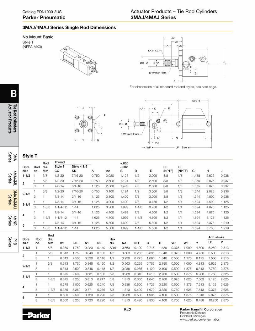
Parker Hannifin CorporationPneumatic DivisionRichland, Michiganwww.parker.com/pneumatics
B42
Catalog PDN1000-3US
Parker Pneumatic
B
Tie Rod Cylinders Actuator Products
3MA
Series4M
A/4ML
Series3M
AJ/4MAJ
Series4M
NR
SeriesP1D
Series
3MAJ/4MAJ Series Single Rod Dimensions
No Mount BasicStyle T
(NFPA MX0)
1
N
N
N
A
LF Stro e
F
F
Stro e
K
ØØ B
VDN1 G
WF
KK
D Wrench Flats
D LCK
NLCK
ØØ B
VDAWF
K
KK or CC
LAF
ØNAD L
CK
NLCK
D Wrench Flats
For dimensions of all standard rod end styles, see next page.
Bore size
Rod no.
Rod dia. MM K2 LAF N1 N2
Hex N3 NA NR Q R VD WF Y
Add stroke
LF P
1-1/2 1 5/8 0.250 1.750 0.220 0.140 5/16 0.563 0.190 0.715 1.430 0.375 1.000 4.500 6.250 2.313
2 1 5/8 0.313 1.750 0.340 0.130 1/2 0.563 0.265 0.895 1.840 0.375 1.000 4.750 6.500 2.313
3 1 0.313 2.500 0.338 0.146 1/2 0.938 0.275 1.065 1.840 0.500 1.375 6.125 7.500 2.313
2-1/2 1 5/8 0.313 1.750 0.346 0.150 1/2 0.563 0.265 0.755 2.190 0.500 1.000 4.813 6.625 2.375
3 1 0.313 2.500 0.346 0.148 1/2 0.938 0.265 1.120 2.190 0.500 1.375 6.313 7.750 2.375
3-1/4 1 1 0.375 2.500 0.631 0.180 5/8 0.938 0.340 1.510 2.760 0.500 1.375 6.938 8.750 2.625
3 1-3/8 0.375 3.250 0.813 0.247 5/8 1.313 0.350 1.645 2.760 0.625 1.625 7.563 9.125 2.625
4 1 1 0.375 2.500 0.625 0.240 7/8 0.938 0.500 1.725 3.320 0.500 1.375 7.313 9.125 2.625
3 1-3/8 0.375 3.250 0.771 0.276 7/8 1.313 0.490 1.679 3.320 0.750 1.625 7.813 9.375 2.625
5 1 1 0.500 2.500 0.720 0.220 7/8 0.938 0.500 1.995 4.100 0.500 1.375 7.813 9.875 2.875
3 1-3/8 0.500 3.250 0.720 0.220 7/8 1.313 0.490 2.330 4.100 0.750 1.625 8.438 10.250 2.875
Bore size
Rod no.
Rod dia. MM
Thread
A AA
+.000 -.002 B D E
EE (NPTF)
EF (NPTF)
G H
J
Style 8 Style 4 & 9 CC KK
1-1/2 1 5/8 1/2-20 7/16-20 0.750 2.020 1.124 1/2 2.000 3/8 1/8 1.438 2.625 0.938
2 1 5/8 1/2-20 7/16-20 0.750 2.600 1.124 1/2 2.500 3/8 1/8 1.375 2.875 0.937
3 1 7/8-14 3/4-16 1.125 2.600 1.499 7/8 2.500 3/8 1/8 1.375 3.875 0.937
2-1/2 1 5/8 1/2-20 7/16-20 0.750 3.100 1.124 1/2 3.000 3/8 1/8 1.344 2.875 0.938
3 1 7/8-14 3/4-16 1.125 3.100 1.499 7/8 3.000 3/8 1/8 1.344 4.000 0.938
3-1/4 1 1 7/8-14 3/4-16 1.125 3.900 1.499 7/8 3.750 1/2 1/4 1.594 4.500 1.125
3 1-3/8 1-1/4-12 1-14 1.625 3.900 1.999 1-1/8 3.750 1/2 1/4 1.594 4.875 1.125
4 1 1 7/8-14 3/4-16 1.125 4.700 1.499 7/8 4.500 1/2 1/4 1.594 4.875 1.125
3 1-3/8 1-1/4-12 1-14 1.625 4.700 1.999 1-1/8 4.500 1/2 1/4 1.594 5.125 1.125
5 1 1 7/8-14 3/4-16 1.125 5.800 1.499 7/8 5.500 1/2 1/4 1.594 5.375 1.219
3 1-3/8 1-1/4-12 1-14 1.625 5.800 1.999 1-1/8 5.500 1/2 1/4 1.594 5.750 1.219
Style T
Actuator Products – Tie Rod Cylinders3MAJ/4MAJ Series
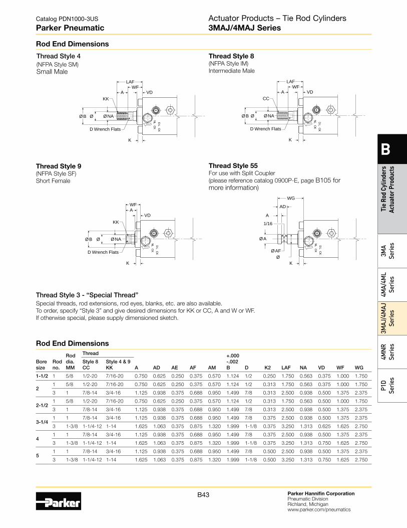
Parker Hannifin CorporationPneumatic DivisionRichland, Michiganwww.parker.com/pneumatics
B43
Catalog PDN1000-3US
Parker Pneumatic
B
Tie
Rod
Cylin
ders
Ac
tuat
or P
rodu
cts
3MA
Serie
s4M
A/4M
L Se
ries
3MAJ
/4M
AJ
Serie
s4M
NR
Serie
sP1
D Se
ries
Rod End Dimensions
ØØ B
VDAWF
K
KK
ØNA
D LCK
NLCK
D Wrench Flats
AD
A
K
WG
1/16
ØA
ØAFØ
D LCK
NLCK
Thread Style 3 - “Special Thread”Special threads, rod extensions, rod eyes, blanks, etc. are also available.
To order, specify “Style 3” and give desired dimensions for KK or CC, A and W or WF.
If otherwise special, please supply dimensioned sketch.
Thread Style 4(NFPA Style SM)
Small Male
Thread Style 8(NFPA Style IM)
Intermediate Male
Thread Style 9(NFPA Style SF)
Short Female
Thread Style 55For use with Split Coupler
(please reference catalog 0900P-E, page B105 for more information)
Bore size
Rod no.
Rod dia. MM
Thread
A AD AE AF AM
+.000 -.002 B D K2 LAF NA
VD WF
WG
Style 8 CC
Style 4 & 9 KK
1-1/2 1 5/8 1/2-20 7/16-20 0.750 0.625 0.250 0.375 0.570 1.124 1/2 0.250 1.750 0.563 0.375 1.000 1.750
2 1 5/8 1/2-20 7/16-20 0.750 0.625 0.250 0.375 0.570 1.124 1/2 0.313 1.750 0.563 0.375 1.000 1.750
3 1 7/8-14 3/4-16 1.125 0.938 0.375 0.688 0.950 1.499 7/8 0.313 2.500 0.938 0.500 1.375 2.375
2-1/2 1 5/8 1/2-20 7/16-20 0.750 0.625 0.250 0.375 0.570 1.124 1/2 0.313 1.750 0.563 0.500 1.000 1.750
3 1 7/8-14 3/4-16 1.125 0.938 0.375 0.688 0.950 1.499 7/8 0.313 2.500 0.938 0.500 1.375 2.375
3-1/4 1 1 7/8-14 3/4-16 1.125 0.938 0.375 0.688 0.950 1.499 7/8 0.375 2.500 0.938 0.500 1.375 2.375
3 1-3/8 1-1/4-12 1-14 1.625 1.063 0.375 0.875 1.320 1.999 1-1/8 0.375 3.250 1.313 0.625 1.625 2.750
4 1 1 7/8-14 3/4-16 1.125 0.938 0.375 0.688 0.950 1.499 7/8 0.375 2.500 0.938 0.500 1.375 2.375
3 1-3/8 1-1/4-12 1-14 1.625 1.063 0.375 0.875 1.320 1.999 1-1/8 0.375 3.250 1.313 0.750 1.625 2.750
5 1 1 7/8-14 3/4-16 1.125 0.938 0.375 0.688 0.950 1.499 7/8 0.500 2.500 0.938 0.500 1.375 2.375
3 1-3/8 1-1/4-12 1-14 1.625 1.063 0.375 0.875 1.320 1.999 1-1/8 0.500 3.250 1.313 0.750 1.625 2.750
Rod End Dimensions
ØØ B
VDAWF
K
KK
LAF
ØNA
D LCK
NLCK
D Wrench Flats
ØØ B
VDAWF
K
CC
LAF
ØNA
D LCK
NLCK
D Wrench Flats
Actuator Products – Tie Rod Cylinders3MAJ/4MAJ Series
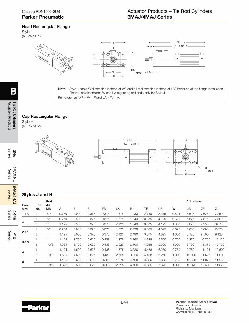
Parker Hannifin CorporationPneumatic DivisionRichland, Michiganwww.parker.com/pneumatics
B44
Catalog PDN1000-3US
Parker Pneumatic
B
Tie Rod Cylinders Actuator Products
3MA
Series4M
A/4ML
Series3M
AJ/4MAJ
Series4M
NR
SeriesP1D
Series
Head Rectangular FlangeStyle J
(NFPA MF1)
Cap Rectangular FlangeStyle H
(NFPA MF2)
1 LB Stro e
F
W
LA
F
F
1
FB oles
Stro e
1LB Stro e
F
F
F
1
FB oles
F Stro e
Boresize
Rodno.
Roddia. MM A E F FB LA R1 TF UF W
Add stroke
LB ZF ZJ
1-1/2 1 5/8 0.750 2.000 0.375 0.313 1.375 1.430 2.750 3.375 0.625 6.625 7.625 7.250
21 5/8 0.750 2.500 0.375 0.375 1.375 1.840 3.375 4.125 0.625 6.875 7.875 7.500
3 1 1.125 2.500 0.375 0.375 2.125 1.840 3.375 4.125 1.000 7.875 9.250 8.875
2-1/21 5/8 0.750 3.000 0.375 0.375 1.375 2.190 3.875 4.625 0.625 7.000 8.000 7.625
3 1 1.125 3.000 0.375 0.375 2.125 2.190 3.875 4.625 1.000 8.125 9.500 9.125
3-1/41 1 1.125 3.750 0.625 0.438 1.875 2.760 4.688 5.500 0.750 9.375 10.750 10.125
3 1-3/8 1.625 3.750 0.625 0.438 2.625 2.760 4.688 5.500 1.000 9.750 11.375 10.750
41 1 1.125 4.500 0.625 0.438 1.875 3.320 5.438 6.250 0.750 9.750 11.125 10.500
3 1-3/8 1.625 4.500 0.625 0.438 2.625 3.320 5.438 6.250 1.000 10.000 11.625 11.000
51 1 1.125 5.500 0.625 0.563 1.875 4.100 6.625 7.625 0.750 10.500 11.875 11.250
3 1-3/8 1.625 5.500 0.625 0.563 2.625 4.100 6.625 7.625 1.000 10.875 12.500 11.875
Styles J and H
Note: Style J has a W dimension instead of WF and a LA dimension instead of LAF because of the flange installation.
Please use dimensions W and LA regarding rod ends only for Style J.
For reference, WF = W + F and LA = W + A.
Actuator Products – Tie Rod Cylinders3MAJ/4MAJ Series

Parker Hannifin CorporationPneumatic DivisionRichland, Michiganwww.parker.com/pneumatics
B45
Catalog PDN1000-3US
Parker Pneumatic
B
Tie
Rod
Cylin
ders
Ac
tuat
or P
rodu
cts
3MA
Serie
s4M
A/4M
L Se
ries
3MAJ
/4M
AJ
Serie
s4M
NR
Serie
sP1
D Se
ries
Tie Rods Extended Cap End MountStyle TC
(NFPA MX2)
Tie Rods Extended Both Ends MountStyle TD
(NFPA MX1)
Tie Rods Extended Head End MountStyle TB
(NFPA MX3)
1 DD
BB
AA
1
K
DD
AA
BB
1
K
DD DD
BB
AA
BB
Bore size
Rod no.
Rod dia. MM AA BB DD E K R
1-1/2 1 5/8 2.020 1.000 1/4-28 2.000 0.250 1.430
2 1 5/8 2.600 1.125 5/16-24 2.500 0.313 1.840
3 1 2.600 1.125 5/16-24 2.500 0.313 1.840
2-1/2 1 5/8 3.100 1.125 5/16-24 3.000 0.313 2.190
3 1 3.100 1.125 5/16-24 3.000 0.313 2.190
3-1/4 1 1 3.900 1.375 3/8-24 3.750 0.375 2.760
3 1-3/8 3.900 1.375 3/8-24 3.750 0.375 2.760
4 1 1 4.700 1.375 3/8-24 4.500 0.375 3.320
3 1-3/8 4.700 1.375 3/8-24 4.500 0.375 3.320
5 1 1 5.800 1.813 1/2-20 5.500 0.438 4.100
3 1-3/8 5.800 1.813 1/2-20 5.500 0.438 4.100
Styles TB, TC and TD
Actuator Products – Tie Rod Cylinders3MAJ/4MAJ Series

Parker Hannifin CorporationPneumatic DivisionRichland, Michiganwww.parker.com/pneumatics
B46
Catalog PDN1000-3US
Parker Pneumatic
B
Tie Rod Cylinders Actuator Products
3MA
Series4M
A/4ML
Series3M
AJ/4MAJ
Series4M
NR
SeriesP1D
Series
Side Lug MountStyle C (only 4MAJ)
(NFPA MS2)
Side Tap MountStyle F
(NFPA MS4)
1SB oles
SW SW SWG
SL
SWSS S SS Stro e
1
N hread ND Dee a ed t oles
N SN Stro e
Bore size
Rod no.
Rod dia. MM E ND NT
+/-.003 TH TN XT
Add stroke SN
1-1/2 1 5/8 2.000 0.375 1/4-20 0.993 0.625 4.563 2.250
2 1 5/8 2.500 0.438 5/16-18 1.243 0.875 4.813 2.250
3 1 2.500 0.375 5/16-18 1.243 0.875 6.188 2.250
2-1/2 1 5/8 3.000 0.625 3/8-16 1.493 1.250 4.813 2.375
3 1 3.000 0.625 3/8-16 1.493 1.250 6.313 2.375
3-1/4 1 1 3.750 0.750 1/2-13 1.868 1.500 6.938 2.625
3 1-3/8 3.750 0.750 1/2-13 1.868 1.500 7.563 2.625
4 1 1 4.500 0.750 1/2-13 2.243 2.063 7.313 2.625
3 1-3/8 4.500 0.750 1/2-13 2.243 2.063 7.813 2.625
5 1 1 5.500 0.938 5/8-11 2.743 2.688 7.813 2.875
3 1-3/8 5.500 0.938 5/8-11 2.743 2.688 8.438 2.875
Bore size
Rod no.
Rod dia. MM E G J
+/-.003 LH SB ST SW TS US XS
Add stroke SS
1-1/2 1 5/8 2.000 1.438 0.938 0.993 0.438 0.500 0.375 2.750 3.500 4.000 2.875
2 1 5/8 2.500 1.375 0.937 1.243 0.438 0.500 0.375 3.250 4.000 4.250 2.875
3 1 2.500 1.375 0.937 1.243 0.438 0.500 0.375 3.250 4.000 5.625 2.875
2-1/2 1 5/8 3.000 1.344 0.938 1.493 0.438 0.500 0.375 3.750 4.500 4.250 3.000
3 1 3.000 1.344 0.938 1.493 0.438 0.500 0.375 3.750 4.500 5.750 3.000
3-1/4 1 1 3.750 1.594 1.125 1.868 0.563 0.750 0.500 4.750 5.750 6.375 3.250
3 1-3/8 3.750 1.594 1.125 1.868 0.563 0.750 0.500 4.750 5.750 7.000 3.250
4 1 1 4.500 1.594 1.125 2.243 0.563 0.750 0.500 5.500 6.500 6.750 3.250
3 1-3/8 4.500 1.594 1.125 2.243 0.563 0.750 0.500 5.500 6.500 7.250 3.250
5 1 1 5.500 1.594 1.219 2.743 0.813 1.000 0.688 6.875 8.250 7.438 3.125
3 1-3/8 5.500 1.594 1.219 2.743 0.813 1.000 0.688 6.875 8.250 8.063 3.125
Style F
Style C
Actuator Products – Tie Rod Cylinders3MAJ/4MAJ Series

Parker Hannifin CorporationPneumatic DivisionRichland, Michiganwww.parker.com/pneumatics
B47
Catalog PDN1000-3US
Parker Pneumatic
B
Tie
Rod
Cylin
ders
Ac
tuat
or P
rodu
cts
3MA
Serie
s4M
A/4M
L Se
ries
3MAJ
/4M
AJ
Serie
s4M
NR
Serie
sP1
D Se
ries
Side End Angle MountStyle CB
(NFPA MS1)
Side End Lug MountStyle G
(NFPA MS7)
AAL1
S
AB6 oles
1
SA Stro eA
A AL
A
A
D LCK
NLCK
1
Stro e Stro e
S Stro eL
B oles
G
Bore size
Rod no.
Rod dia. MM E EB EL EM EO ET
+/-.003 GH R
Add stroke
SE XE ZE
1-1/2 1 5/8 2.000 0.281 0.750 1.125 0.250 0.563 0.993 1.430 8.125 8.000 8.250
2 1 5/8 2.500 0.344 0.938 1.313 0.313 0.688 1.243 1.840 8.750 8.438 8.750
3 1 2.500 0.344 0.938 1.313 0.313 0.688 1.243 1.840 9.750 9.813 10.125
2-1/2 1 5/8 3.000 0.344 1.063 1.438 0.313 0.813 1.493 2.190 9.125 8.688 9.000
3 1 3.000 0.344 1.063 1.438 0.313 0.813 1.493 2.190 10.250 10.188 10.500
3-1/4 1 1 3.750 0.406 0.875 1.500 0.375 1.000 1.868 2.760 11.125 11.000 11.375
3 1-3/8 3.750 0.406 0.875 1.500 0.375 1.000 1.868 2.760 11.500 11.625 12.000
4 1 1 4.500 0.406 1.000 1.625 0.375 1.188 2.243 3.320 11.750 11.500 11.875
3 1-3/8 4.500 0.406 1.000 1.625 0.375 1.188 2.243 3.320 12.000 12.000 12.375
Bore size
Rod no.
Rod dia. MM AB AH AL AL1 AO AT E S
Add stroke
SA
1-1/2 1 5/8 0.438 1.188 1.000 1.000 0.375 0.125 2.000 1.250 8.250
2 1 5/8 0.438 1.438 1.000 1.000 0.375 0.125 2.500 1.750 8.500
3 1 0.438 1.438 1.000 1.000 0.375 0.125 2.500 1.750 9.500
2-1/2 1 5/8 0.438 1.625 1.000 1.000 0.375 0.125 3.000 2.250 8.625
3 1 0.438 1.625 1.000 1.000 0.375 0.125 3.000 2.250 9.750
3-1/4 1 1 0.563 1.938 1.250 1.250 0.500 0.125 3.750 2.750 11.250
3 1-3/8 0.563 1.938 1.250 1.250 0.500 0.125 3.750 2.750 11.625
4 1 1 0.563 2.250 1.875 1.250 0.500 0.125 4.500 3.500 12.250
3 1-3/8 0.563 2.250 1.875 1.250 0.500 0.125 4.500 3.500 12.500
5 1 1 0.688 2.750 1.375 1.375 0.625 0.188 5.500 4.250 12.625
3 1-3/8 0.688 2.750 1.375 1.375 0.625 0.188 5.500 4.250 13.000
Style G
Style CB
Actuator Products – Tie Rod Cylinders3MAJ/4MAJ Series
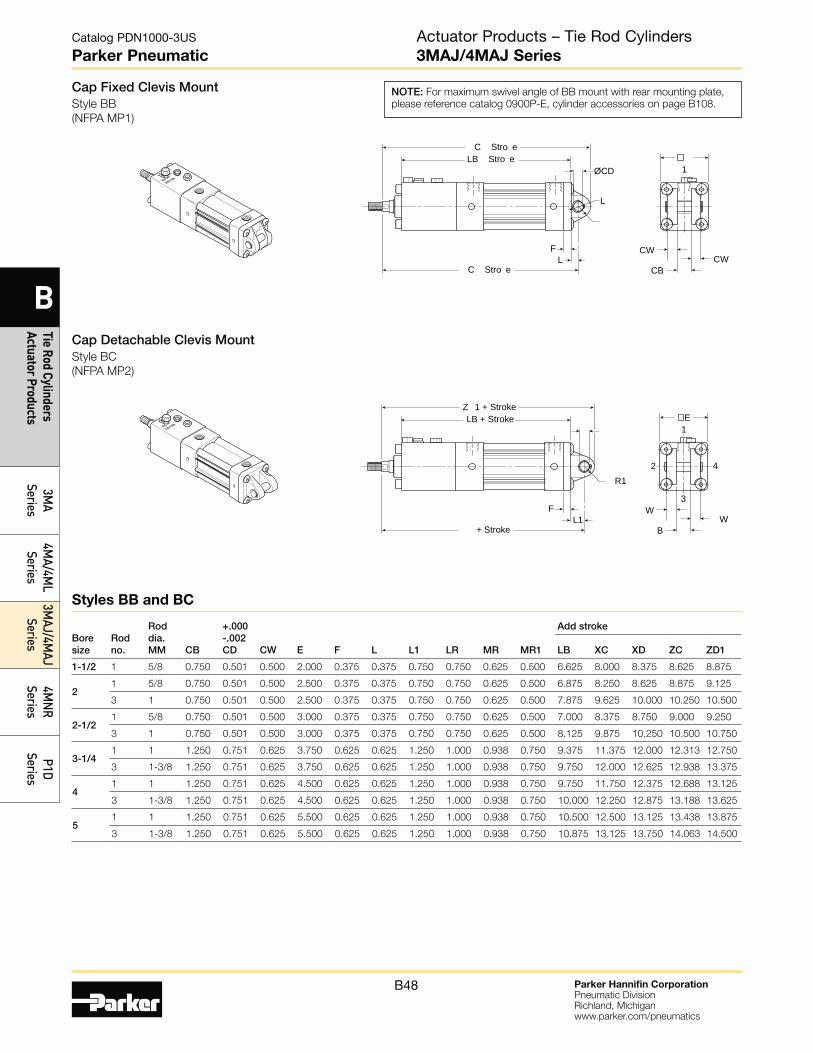
Parker Hannifin CorporationPneumatic DivisionRichland, Michiganwww.parker.com/pneumatics
B48
Catalog PDN1000-3US
Parker Pneumatic
B
Tie Rod Cylinders Actuator Products
3MA
Series4M
A/4ML
Series3M
AJ/4MAJ
Series4M
NR
SeriesP1D
Series
Cap Fixed Clevis MountStyle BB
(NFPA MP1)
Cap Detachable Clevis MountStyle BC
(NFPA MP2)
1LB Stro e
F CWCW
CB
ØCD
L
L
C Stro e
C Stro e
4
1
2
3
LB + Stroke
F WW
B
R1
L1
Z 1 + Stroke
+ Stroke
E
NOTE: For maximum swivel angle of BB mount with rear mounting plate,
please reference catalog 0900P-E, cylinder accessories on page B108.
Bore size
Rod no.
Rod dia. MM CB
+.000 -.002 CD CW E F L L1 LR MR MR1
Add stroke
LB XC XD ZC ZD1
1-1/2 1 5/8 0.750 0.501 0.500 2.000 0.375 0.375 0.750 0.750 0.625 0.500 6.625 8.000 8.375 8.625 8.875
2 1 5/8 0.750 0.501 0.500 2.500 0.375 0.375 0.750 0.750 0.625 0.500 6.875 8.250 8.625 8.875 9.125
3 1 0.750 0.501 0.500 2.500 0.375 0.375 0.750 0.750 0.625 0.500 7.875 9.625 10.000 10.250 10.500
2-1/2 1 5/8 0.750 0.501 0.500 3.000 0.375 0.375 0.750 0.750 0.625 0.500 7.000 8.375 8.750 9.000 9.250
3 1 0.750 0.501 0.500 3.000 0.375 0.375 0.750 0.750 0.625 0.500 8.125 9.875 10.250 10.500 10.750
3-1/4 1 1 1.250 0.751 0.625 3.750 0.625 0.625 1.250 1.000 0.938 0.750 9.375 11.375 12.000 12.313 12.750
3 1-3/8 1.250 0.751 0.625 3.750 0.625 0.625 1.250 1.000 0.938 0.750 9.750 12.000 12.625 12.938 13.375
4 1 1 1.250 0.751 0.625 4.500 0.625 0.625 1.250 1.000 0.938 0.750 9.750 11.750 12.375 12.688 13.125
3 1-3/8 1.250 0.751 0.625 4.500 0.625 0.625 1.250 1.000 0.938 0.750 10.000 12.250 12.875 13.188 13.625
5 1 1 1.250 0.751 0.625 5.500 0.625 0.625 1.250 1.000 0.938 0.750 10.500 12.500 13.125 13.438 13.875
3 1-3/8 1.250 0.751 0.625 5.500 0.625 0.625 1.250 1.000 0.938 0.750 10.875 13.125 13.750 14.063 14.500
Styles BB and BC
Actuator Products – Tie Rod Cylinders3MAJ/4MAJ Series
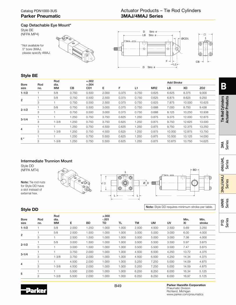
Parker Hannifin CorporationPneumatic DivisionRichland, Michiganwww.parker.com/pneumatics
B49
Catalog PDN1000-3US
Parker Pneumatic
B
Tie
Rod
Cylin
ders
Ac
tuat
or P
rodu
cts
3MA
Serie
s4M
A/4M
L Se
ries
3MAJ
/4M
AJ
Serie
s4M
NR
Serie
sP1
D Se
ries
Cap Detachable Eye Mount*Style BE
(NFPA MP4)
* Not available for
5" bore 3MAJ,
please specify 4MAJ.
1LB Stro e
F CB
ØCD1
L1
D Stro e
D Stro e
Bore size
Rod no.
Rod dia. MM CB
+.002 +.004 CD1 E F L1 MR2
Add Stroke
LB XD ZD2
1-1/2 1 5/8 0.750 0.500 2.000 0.375 0.750 0.625 6.625 8.375 9.000
2 1 5/8 0.750 0.500 2.500 0.375 0.750 0.625 6.875 8.625 9.250
3 1 0.750 0.500 2.500 0.375 0.750 0.625 7.875 10.000 10.625
2-1/2 1 5/8 0.750 0.500 3.000 0.375 0.750 0.688 7.000 8.750 9.438
3 1 0.750 0.500 3.000 0.375 0.750 0.688 8.125 10.250 10.938
3-1/4 1 1 1.250 0.750 3.750 0.625 1.250 0.875 9.375 12.000 12.875
3 1-3/8 1.250 0.750 3.750 0.625 1.250 0.875 9.750 12.625 13.500
4 1 1 1.250 0.750 4.500 0.625 1.250 0.875 9.750 12.375 13.250
3 1-3/8 1.250 0.750 4.500 0.625 1.250 0.875 10.000 12.875 13.750
5 *1 1 1.250 0.750 5.500 0.625 1.250 0.875 10.500 13.125 14.000
3 1-3/8 1.250 0.750 5.500 0.625 1.250 0.875 10.875 13.750 14.625
Style DD
Style BE
Intermediate Trunnion MountStyle DD
(NFPA MT4)
Note: Tie rod nuts
for Style DD have
a slot instead of
external hex.
1BD
L L
V Ø D
Note: Style DD requires minimum stroke per table.
Bore size
Rod no.
Rod dia. MM E BD
+.000 -.001 TD TL TM UM UV
Min. XI
Min. stroke
1-1/2 1 5/8 2.000 1.250 1.000 1.000 2.500 4.500 2.500 5.69 3.250
2 1 5/8 2.500 1.500 1.000 1.000 3.000 5.000 3.000 6.00 4.000
3 1 2.500 1.500 1.000 1.000 3.000 5.000 3.000 7.38 4.000
2-1/2 1 5/8 3.000 1.500 1.000 1.000 3.500 5.500 3.500 5.97 3.875
3 1 3.000 1.500 1.000 1.000 3.500 5.500 3.500 7.47 3.875
3-1/4 1 1 3.750 2.000 1.000 1.000 4.500 6.500 4.250 13.72 4.375
3 1-3/8 3.750 2.000 1.000 1.000 4.500 6.500 4.250 14.34 4.375
4 1 1 4.500 2.000 1.000 1.000 5.250 7.250 5.000 14.09 4.875
3 1-3/8 4.500 2.000 1.000 1.000 5.250 7.250 5.000 14.59 4.875
5 1 1 5.500 2.000 1.000 1.000 6.250 8.250 6.000 16.34 5.125
3 1-3/8 5.500 2.000 1.000 1.000 6.250 8.250 6.000 16.97 5.125
Actuator Products – Tie Rod Cylinders3MAJ/4MAJ Series
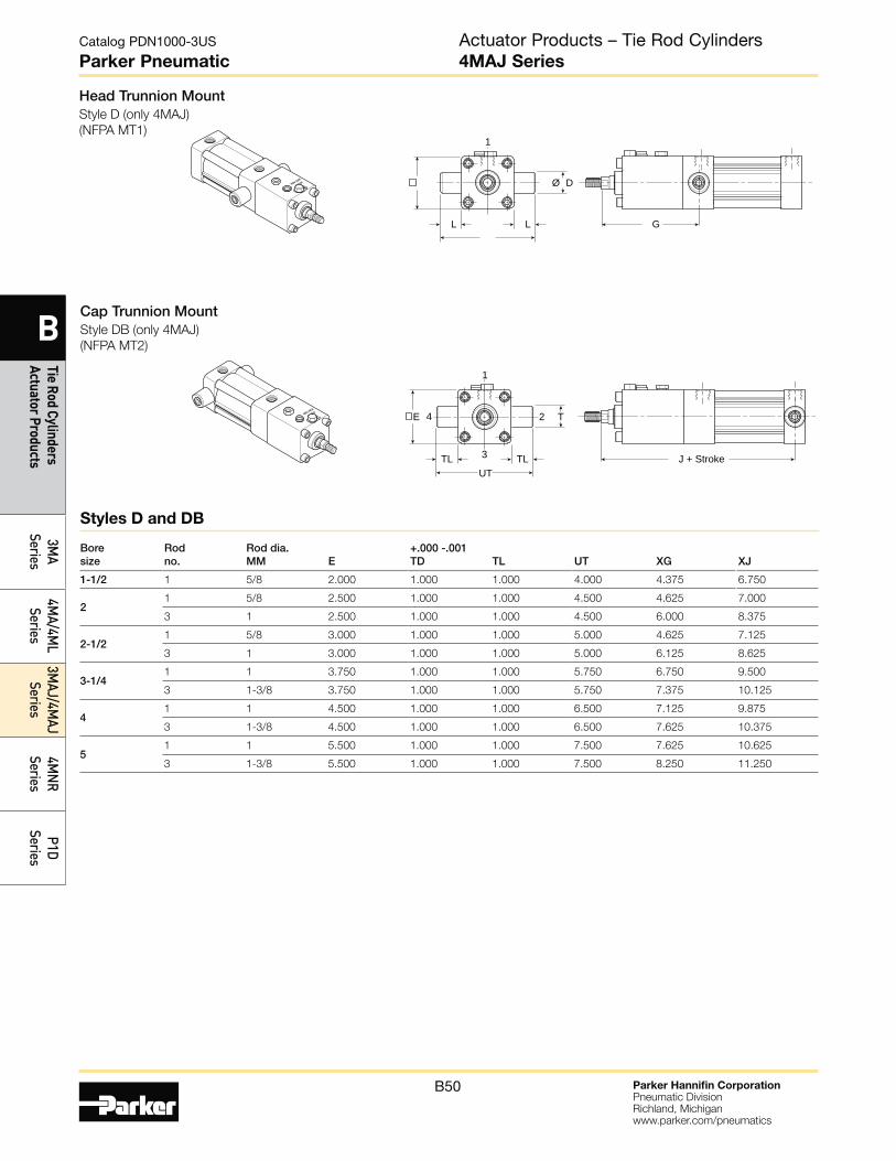
Parker Hannifin CorporationPneumatic DivisionRichland, Michiganwww.parker.com/pneumatics
B50
Catalog PDN1000-3US
Parker Pneumatic
B
Tie Rod Cylinders Actuator Products
3MA
Series4M
A/4ML
Series3M
AJ/4MAJ
Series4M
NR
SeriesP1D
Series
Head Trunnion MountStyle D (only 4MAJ)
(NFPA MT1)
Cap Trunnion MountStyle DB (only 4MAJ)
(NFPA MT2)
1
GL L
Ø D
4
1
2
3 J + StrokeTLUT
TL
TE
Bore size
Rod no.
Rod dia. MM E
+.000 -.001 TD TL UT XG XJ
1-1/2 1 5/8 2.000 1.000 1.000 4.000 4.375 6.750
2 1 5/8 2.500 1.000 1.000 4.500 4.625 7.000
3 1 2.500 1.000 1.000 4.500 6.000 8.375
2-1/2 1 5/8 3.000 1.000 1.000 5.000 4.625 7.125
3 1 3.000 1.000 1.000 5.000 6.125 8.625
3-1/4 1 1 3.750 1.000 1.000 5.750 6.750 9.500
3 1-3/8 3.750 1.000 1.000 5.750 7.375 10.125
4 1 1 4.500 1.000 1.000 6.500 7.125 9.875
3 1-3/8 4.500 1.000 1.000 6.500 7.625 10.375
5 1 1 5.500 1.000 1.000 7.500 7.625 10.625
3 1-3/8 5.500 1.000 1.000 7.500 8.250 11.250
Styles D and DB
Actuator Products – Tie Rod Cylinders4MAJ Series
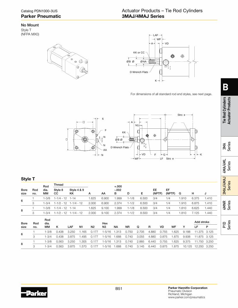
Parker Hannifin CorporationPneumatic DivisionRichland, Michiganwww.parker.com/pneumatics
B51
Catalog PDN1000-3US
Parker Pneumatic
B
Tie
Rod
Cylin
ders
Ac
tuat
or P
rodu
cts
3MA
Serie
s4M
A/4M
L Se
ries
3MAJ
/4M
AJ
Serie
s4M
NR
Serie
sP1
D Se
ries
No Mount Style T
(NFPA MX0)
Stro e
KG F LF Stro eWF
N
Ø Ø B
VD
AN1
N
NAA
KK
D LCK
NLCK
D Wrench Flats
F
6
1
Ø Ø B
VDAWF
K
KK or CC
LAF
ØNA
D LCK
NLCK
D Wrench Flats
For dimensions of all standard rod end styles, see next page.
Bore size
Rod no.
Rod dia. MM K LAF N1 N2
Hex N3 NA NR Q R VD WF Y
Add stroke
LF P
6 1 1-3/8 0.438 3.250 1.165 0.177 1-5/16 1.313 0.750 2.705 4.880 0.755 1.625 9.188 11.375 3.125
3 1-3/4 0.438 3.875 1.495 0.177 1-5/16 1.688 0.740 3.055 4.880 0.875 1.875 9.938 11.875 3.125
8 1 1-3/8 0.563 3.250 1.305 0.177 1-5/16 1.313 0.740 2.885 6.440 0.755 1.625 9.375 11.750 3.250
3 1-3/4 0.563 3.875 1.570 0.177 1-5/16 1.688 0.740 3.145 6.440 0.875 1.875 10.125 12.250 3.250
Bore size
Rod no.
Rod dia. MM
Thread
A AA
+.000 -.002B D E
EE (NPTF)
EF (NPTF)
G H
J
Style 8 CC
Style 4 & 9 KK
6 1 1-3/8 1-1/4 - 12 1-14 1.625 6.900 1.999 1-1/8 6.500 3/4 1/4 1.910 6.375 1.410
3 1-3/4 1-1/2 - 12 1-1/4 - 12 2.000 6.900 2.374 1-1/2 6.500 3/4 1/4 1.910 6.875 1.410
8 1 1-3/8 1-1/4 - 12 1-14 1.625 9.100 1.999 1-1/8 8.500 3/4 1/4 1.810 6.625 1.440
3 1-3/4 1-1/2 - 12 1-1/4 - 12 2.000 9.100 2.374 1-1/2 8.500 3/4 1/4 1.810 7.125 1.440
Style T
Actuator Products – Tie Rod Cylinders3MAJ/4MAJ Series
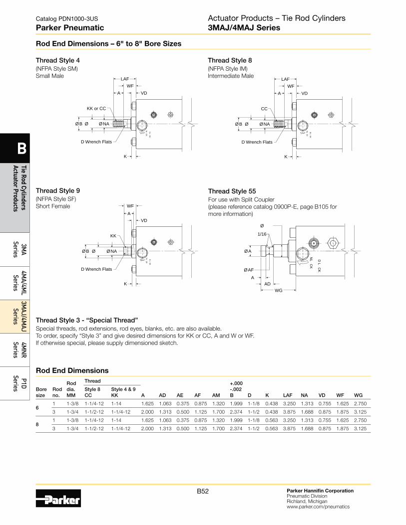
Parker Hannifin CorporationPneumatic DivisionRichland, Michiganwww.parker.com/pneumatics
B52
Catalog PDN1000-3US
Parker Pneumatic
B
Tie Rod Cylinders Actuator Products
3MA
Series4M
A/4ML
Series3M
AJ/4MAJ
Series4M
NR
SeriesP1D
Series
Rod End Dimensions – 6" to 8" Bore Sizes
Thread Style 4(NFPA Style SM)
Small Male
Thread Style 8(NFPA Style IM)
Intermediate Male
Thread Style 9(NFPA Style SF)
Short Female
Thread Style 55For use with Split Coupler
(please reference catalog 0900P-E, page B105 for
more information)
Thread Style 3 - “Special Thread”Special threads, rod extensions, rod eyes, blanks, etc. are also available.
To order, specify “Style 3” and give desired dimensions for KK or CC, A and W or WF.
If otherwise special, please supply dimensioned sketch.
Ø
1/16
Ø A
WGAD
AØAF
D L
CK
NL
CK
Ø Ø B
VDAWF
K
KK
ØNAD L
CK
NLCK
D Wrench Flats
Bore size
Rod no.
Rod dia. MM
Thread
A AD AE AF
AM
+.000-.002B D K LAF NA
VD WF
WG
Style 8 CC
Style 4 & 9 KK
6 1 1-3/8 1-1/4-12 1-14 1.625 1.063 0.375 0.875 1.320 1.999 1-1/8 0.438 3.250 1.313 0.755 1.625 2.750
3 1-3/4 1-1/2-12 1-1/4-12 2.000 1.313 0.500 1.125 1.700 2.374 1-1/2 0.438 3.875 1.688 0.875 1.875 3.125
8 1 1-3/8 1-1/4-12 1-14 1.625 1.063 0.375 0.875 1.320 1.999 1-1/8 0.563 3.250 1.313 0.755 1.625 2.750
3 1-3/4 1-1/2-12 1-1/4-12 2.000 1.313 0.500 1.125 1.700 2.374 1-1/2 0.563 3.875 1.688 0.875 1.875 3.125
Rod End Dimensions
Ø Ø B
VDAWF
K
KK or CC
LAF
ØNA
D LCK
NLCK
D Wrench Flats
Ø Ø B
VDAWF
K
CC
LAF
ØNA
D LCK
NLCK
D Wrench Flats
Actuator Products – Tie Rod Cylinders3MAJ/4MAJ Series
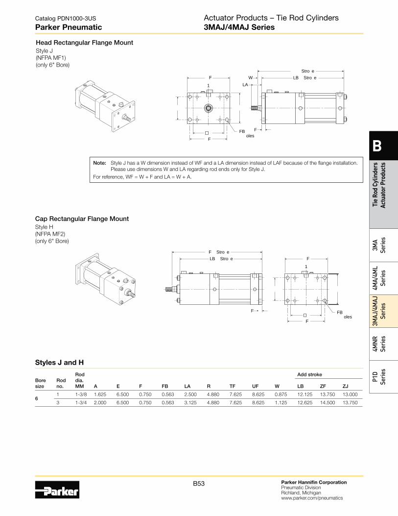
Parker Hannifin CorporationPneumatic DivisionRichland, Michiganwww.parker.com/pneumatics
B53
Catalog PDN1000-3US
Parker Pneumatic
B
Tie
Rod
Cylin
ders
Ac
tuat
or P
rodu
cts
3MA
Serie
s4M
A/4M
L Se
ries
3MAJ
/4M
AJ
Serie
s4M
NR
Serie
sP1
D Se
ries
Head Rectangular Flange MountStyle J
(NFPA MF1)
(only 6" Bore)
Cap Rectangular Flange MountStyle H
(NFPA MF2)
(only 6" Bore)
W1F
F
LA
Stro eLB Stro e
FFB oles
1F
F
F Stro eLB Stro e
F FB oles
Boresize
Rodno.
Roddia.MM A E F FB LA R TF UF W
Add stroke
LB ZF ZJ
61 1-3/8 1.625 6.500 0.750 0.563 2.500 4.880 7.625 8.625 0.875 12.125 13.750 13.000
3 1-3/4 2.000 6.500 0.750 0.563 3.125 4.880 7.625 8.625 1.125 12.625 14.500 13.750
Styles J and H
Note: Style J has a W dimension instead of WF and a LA dimension instead of LAF because of the flange installation.
Please use dimensions W and LA regarding rod ends only for Style J.
For reference, WF = W + F and LA = W + A.
Actuator Products – Tie Rod Cylinders3MAJ/4MAJ Series
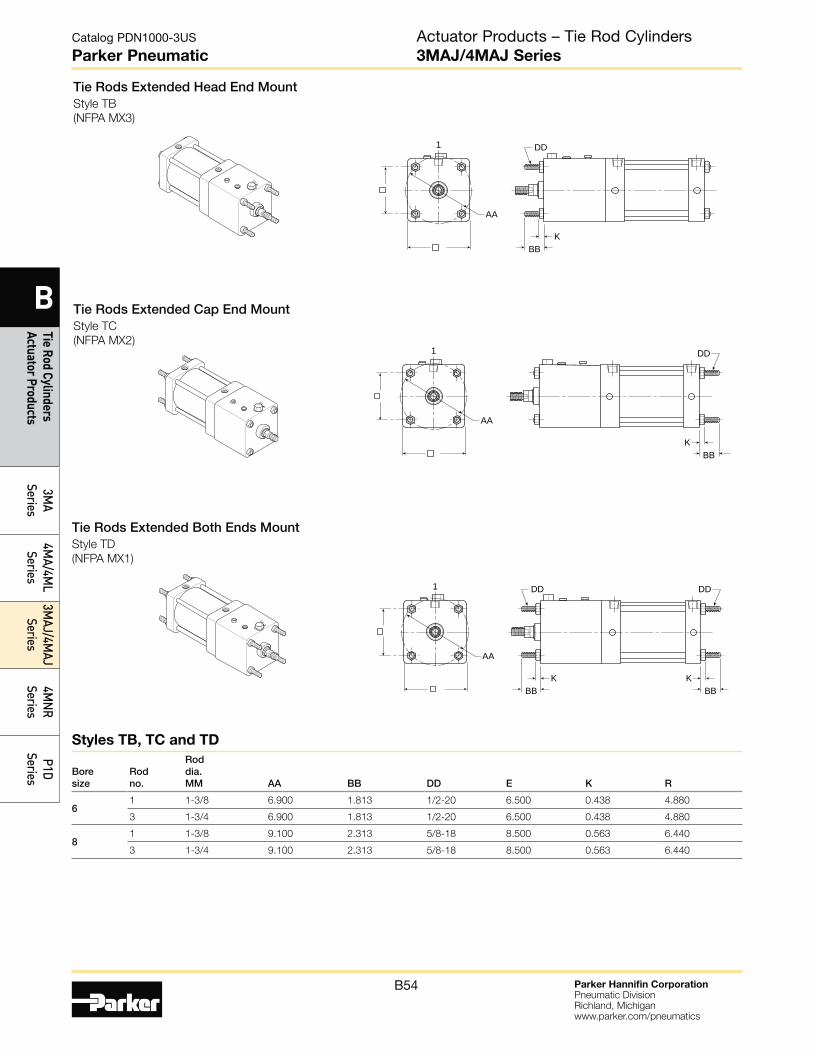
Parker Hannifin CorporationPneumatic DivisionRichland, Michiganwww.parker.com/pneumatics
B54
Catalog PDN1000-3US
Parker Pneumatic
B
Tie Rod Cylinders Actuator Products
3MA
Series4M
A/4ML
Series3M
AJ/4MAJ
Series4M
NR
SeriesP1D
Series
Styles TB, TC and TD
Tie Rods Extended Head End MountStyle TB
(NFPA MX3)
Tie Rods Extended Cap End MountStyle TC
(NFPA MX2)
Tie Rods Extended Both Ends MountStyle TD
(NFPA MX1)
AA
1 DD
BBK
AA
1 DD
BBK
AA
1 DD
BBK
DD
BBK
Bore size
Rod no.
Rod dia. MM AA BB DD E K R
6 1 1-3/8 6.900 1.813 1/2-20 6.500 0.438 4.880
3 1-3/4 6.900 1.813 1/2-20 6.500 0.438 4.880
8 1 1-3/8 9.100 2.313 5/8-18 8.500 0.563 6.440
3 1-3/4 9.100 2.313 5/8-18 8.500 0.563 6.440
Actuator Products – Tie Rod Cylinders3MAJ/4MAJ Series
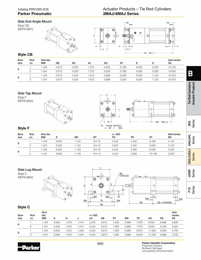
Parker Hannifin CorporationPneumatic DivisionRichland, Michiganwww.parker.com/pneumatics
B55
Catalog PDN1000-3US
Parker Pneumatic
B
Tie
Rod
Cylin
ders
Ac
tuat
or P
rodu
cts
3MA
Serie
s4M
A/4M
L Se
ries
3MAJ
/4M
AJ
Serie
s4M
NR
Serie
sP1
D Se
ries
Side End Angle MountStyle CB
(NFPA MS1)
1
A
AB oles
AL AL A
A
SA Stro e
AA
D LCK
NLCK
AB oles
NN hread ND Dee
a ed t oles
SN Stro e
1
Side Tap MountStyle F
(NFPA MS4)
Bore size
Rod no.
Rod dia. MM E ND NT
+/-.003 TH TN XT
Add stroke SN
6 1 1-3/8 6.500 1.125 3/4-10 3.243 3.250 9.188 3.125
3 1-3/4 6.500 1.125 3/4-10 3.243 3.250 9.938 3.125
8 1 1-3/8 8.500 1.125 3/4-10 4.243 4.500 9.438 3.250
3 1-3/4 8.500 1.125 3/4-10 4.243 4.500 10.188 3.250
Bore size
Rod no.
Rod dia. MM AB AH AL AO AT E S
Add stroke SA
6 1 1-3/8 0.813 3.250 1.375 0.625 0.188 6.500 5.250 14.125
3 1-3/4 0.813 3.250 1.375 0.625 0.188 6.500 5.250 14.625
8 1 1-3/8 0.813 4.250 1.813 0.688 0.250 8.500 7.125 15.375
3 1-3/4 0.813 4.250 1.813 0.688 0.250 8.500 7.125 15.875
Side Lug MountStyle C
(NFPA MS2)
ST
LH
E
US
SW
SW SW
SWTS
SB4 HOLES
1
2
3
4
XS
SW
SS + STROKESW
G J
Bore size
Rod no.
Rod dia. MM E G J
+/-.003 LH SB ST SW TS US XS
Add stroke SS
6 1 1-3/8 6.500 1.910 1.410 3.243 0.813 1.000 0.688 7.875 9.250 8.688 3.625
3 1-3/4 6.500 1.910 1.410 3.243 0.813 1.000 0.688 7.875 9.250 9.438 3.625
8 1 1-3/8 8.500 1.810 1.440 4.243 0.813 1.000 0.688 9.875 11.250 8.938 3.750
3 1-3/4 8.500 1.810 1.440 4.243 0.813 1.000 0.688 9.875 11.250 9.688 3.750
Style C
Style CB
Style F
Actuator Products – Tie Rod Cylinders3MAJ/4MAJ Series
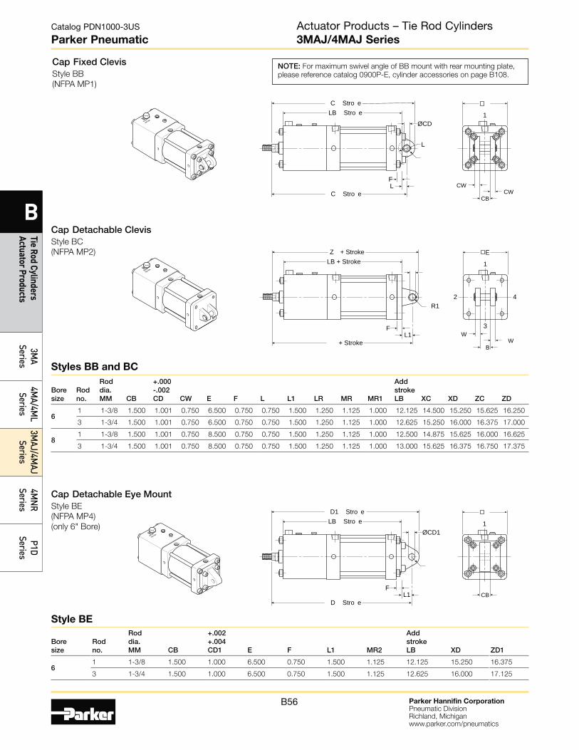
Parker Hannifin CorporationPneumatic DivisionRichland, Michiganwww.parker.com/pneumatics
B56
Catalog PDN1000-3US
Parker Pneumatic
B
Tie Rod Cylinders Actuator Products
3MA
Series4M
A/4ML
Series3M
AJ/4MAJ
Series4M
NR
SeriesP1D
Series
Style BE
Styles BB and BC
Cap Fixed ClevisStyle BB
(NFPA MP1)
Cap Detachable ClevisStyle BC
(NFPA MP2)
Cap Detachable Eye MountStyle BE
(NFPA MP4)
(only 6" Bore)
1
C Stro eLB Stro e
C Stro e
FCW
CWCB
ØCD
L
L
1
3
2 4
Z + StrokeLB + Stroke
+ Stroke
FW
WB
R1
L1
E
Bore size
Rod no.
Rod dia. MM CB
+.000 -.002 CD CW E F L L1 LR MR MR1
Add stroke LB
XC XD ZC ZD
6 1 1-3/8 1.500 1.001 0.750 6.500 0.750 0.750 1.500 1.250 1.125 1.000 12.125 14.500 15.250 15.625 16.250
3 1-3/4 1.500 1.001 0.750 6.500 0.750 0.750 1.500 1.250 1.125 1.000 12.625 15.250 16.000 16.375 17.000
8 1 1-3/8 1.500 1.001 0.750 8.500 0.750 0.750 1.500 1.250 1.125 1.000 12.500 14.875 15.625 16.000 16.625
3 1-3/4 1.500 1.001 0.750 8.500 0.750 0.750 1.500 1.250 1.125 1.000 13.000 15.625 16.375 16.750 17.375
Bore size
Rod no.
Rod dia. MM CB
+.002 +.004 CD1 E F L1 MR2
Add stroke LB
XD ZD1
6 1 1-3/8 1.500 1.000 6.500 0.750 1.500 1.125 12.125 15.250 16.375
3 1-3/4 1.500 1.000 6.500 0.750 1.500 1.125 12.625 16.000 17.125
1
D1 Stro eLB Stro e
D Stro e
FCB
ØCD1
L1
NOTE: For maximum swivel angle of BB mount with rear mounting plate,
please reference catalog 0900P-E, cylinder accessories on page B108.
Actuator Products – Tie Rod Cylinders3MAJ/4MAJ Series
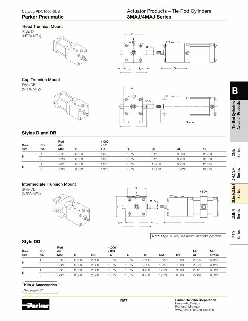
Parker Hannifin CorporationPneumatic DivisionRichland, Michiganwww.parker.com/pneumatics
B57
Catalog PDN1000-3US
Parker Pneumatic
B
Tie
Rod
Cylin
ders
Ac
tuat
or P
rodu
cts
3MA
Serie
s4M
A/4M
L Se
ries
3MAJ
/4M
AJ
Serie
s4M
NR
Serie
sP1
D Se
ries
Head Trunnion MountStyle D
(NFPA MT1)
Cap Trunnion MountStyle DB
(NFPA MT2)
L L G
1
Ø D
L L Stro e
1
Ø D
Bore size
Rod no.
Rod dia. MM E
+.000 -.001 TD TL UT XG XJ
6 1 1-3/8 6.500 1.375 1.375 9.250 9.000 12.250
3 1-3/4 6.500 1.375 1.375 9.250 9.750 13.000
8 1 1-3/8 8.500 1.375 1.375 11.250 9.250 12.625
3 1-3/4 8.500 1.375 1.375 11.250 10.000 13.375
Intermediate Trunnion MountStyle DD
(NFPA MT4)
L L
BD1
V
Ø D
Bore size
Rod no.
Rod dia. MM E BD
+.000 -.001 TD TL TM UM UV
Min. XI
Min. stroke
6 1 1-3/8 6.500 2.500 1.375 1.375 7.625 10.375 7.000 20.16 6.125
3 1-3/4 6.500 2.500 1.375 1.375 7.625 10.375 7.000 20.19 6.125
8 1 1-3/8 8.500 2.500 1.375 1.375 9.750 12.500 9.500 26.31 6.500
3 1-3/4 8.500 2.500 1.375 1.375 9.750 12.500 9.500 27.06 6.500
Styles D and DB
Style DD
Note: Style DD requires minimum stroke per table.
Actuator Products – Tie Rod Cylinders3MAJ/4MAJ Series
Kits & Accessories
See page B37.