3rd lecture shear and moment diagram for determinate beam
DESCRIPTION
lectures in theory of structureTRANSCRIPT
Theory of Structures3rd Lecture (9/10/2012): Analysis of Determinate
Beams;
Shear & Moment Diagrams
Dr Hussein M. Al.Khuzaie; [email protected] 1

Beams
• Members that are slender and support loads applied perpendicular to their longitudinal axis.
Dr Hussein M. Al.Khuzaie; [email protected] 2
Span, L
Distributed Load, w(x) Concentrated Load, P
Longitudinal
Axis

Types of Beams
• Depends on the support configuration
Dr Hussein M. Al.Khuzaie; [email protected] 3
M
Fv
FHFixed
FV FV
FH
Pin
Roller
PinRoller
FVFV
FH
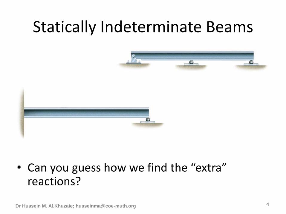
Statically Indeterminate Beams
• Can you guess how we find the “extra” reactions?
Dr Hussein M. Al.Khuzaie; [email protected] 4
Continuous Beam
Propped Cantilever
Beam

Internal Loadings developed in a structure member
• in order to properly design structural components, we must know the distribution of the internal forces within the component.
• In this lecture, we will determine the normal (axial) force, shear, and moment at a point in a structural component.
• Internal loads at a point within a structural component. For a coplanar structure, the internal load at a specified point will consist of a normal (Axial) force, N, a shear force, V, and a bending moment, M.
Dr Hussein M. Al.Khuzaie; [email protected]

Dr Hussein M. Al.Khuzaie; [email protected]
Positive normal (Axial) force, N, tends to elongate the
components. Again, note that the normal (axial) forces
act in opposite directions on either side of the cut.
Positive shear, V, tends to rotate the component
clockwise. Note that the shear is in opposite directions
on either side of a cut through the component.
Positive moment, M, tends to deform the component into
a dish-shaped configuration such that it would hold
water. Again, note that the moment acts in opposite
directions on either side of the cut.

Internal Reactions in Beams
• At any cut in a beam, there are 3 possible internal reactions required for equilibrium: – Normal (Axial) force,
– Shear force,
– Bending moment.
Dr Hussein M. Al.Khuzaie; [email protected]
L
P
a b

Dr Hussein M. Al.Khuzaie; [email protected] 8

Internal Reactions in Beams
• At any cut in a beam, there are 3 possible internal reactions required for equilibrium: – normal force,
– shear force,
– bending moment.
Dr Hussein M. Al.Khuzaie;
Pb/L
x
Left Side of Cut
V
M
N
Positive Directions
Shown!!!

Internal Reactions in Beams
• At any cut in a beam, there are 3 possible internal reactions required for equilibrium: – normal force,
– shear force,
– bending moment.
Dr Hussein M. Al.Khuzaie; [email protected] 10
Pa/L
L - x
Right Side of CutVM
N
Positive Directions
Shown!!!

Finding Internal Reactions
• Pick left side of the cut:– Find the sum of all the vertical forces to the left of
the cut, including V. Solve for shear, V.
– Find the sum of all the horizontal forces to the left of the cut, including N. Solve for axial force, N. It’s usually, but not always, 0.
– Sum the moments of all the forces to the left of the cut about the point of the cut. Include M. Solve for bending moment, M
• Pick the right side of the cut:– Same as above, except to the right of the cut.
Dr Hussein M. Al.Khuzaie; [email protected]

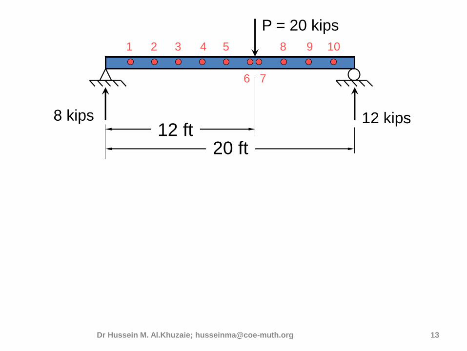
Example: Find the internal reactions at points indicated. All axial force reactions are zero. Points are 2-ft apart.
Dr Hussein M. Al.Khuzaie; [email protected] 12
20 ft
P = 20 kips
12 kips8 kips12 ft
1
7
10
6
2 3 94 5 8
Point 6 is just left of P and Point 7 is just right of P.
20 ft
P = 20 kips
12 kips8 kips12 ft
1
7
10
6
2 3 94 5 8
V(kips)
M(ft-kips)
8 kips
-12 kips
96
4864
4872
24
80
1632
x
xDr Hussein M. Al.Khuzaie; [email protected] 13
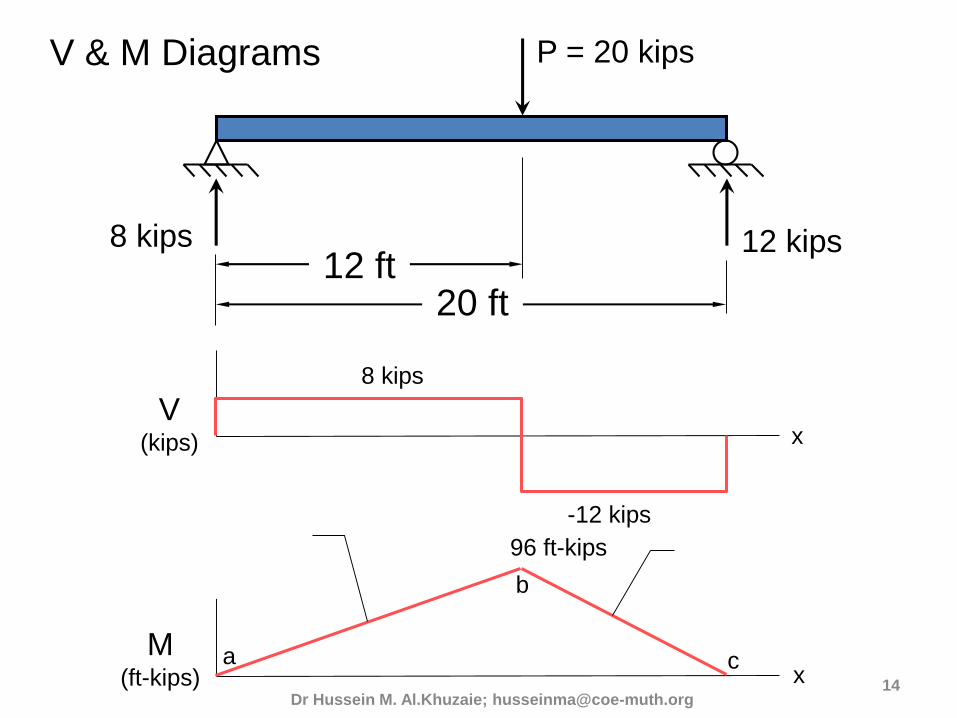
20 ft
P = 20 kips
12 kips8 kips12 ft
V(kips)
M(ft-kips)
8 kips
-12 kips
96 ft-kips
x
x
V & M Diagrams
What is the slope
of this line?
a
b
c
96 ft-kips/12’ = 8 kips
What is the slope
of this line?-12 kips
Dr Hussein M. Al.Khuzaie; [email protected]

20 ft
P = 20 kips
12 kips8 kips12 ft
V(kips)
M(ft-kips)
8 kips
-12 kips
96 ft-kips
x
x
V & M Diagrams
a
b
c
What is the area of
the blue rectangle?
96 ft-kipsWhat is the area of
the green rectangle?
-96 ft-kips
Dr Hussein M. Al.Khuzaie; [email protected]

Draw Some Conclusions
• The magnitude of the shear at a point equals the slope of the moment diagram at that point.
• The area under the shear diagram between two points equals the change in moments between those two points.
• At points where the shear is zero, the moment is a local maximum or minimum.
Dr Hussein M. Al.Khuzaie;

dxxVxM
dxxwxV
functionloadthexw
)()(
)()(
)(
Dr Hussein M. Al.Khuzaie; [email protected] 17
The Relationship Between Load, Shear and
Bending Moment
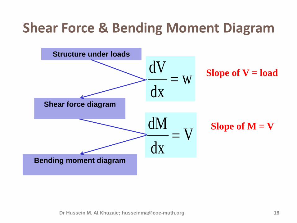
Shear Force & Bending Moment Diagram
Structure under loads
wdx
dV
Vdx
dM
Bending moment diagram
Shear force diagram
Slope of V = load
Slope of M = V
Dr Hussein M. Al.Khuzaie; [email protected] 18
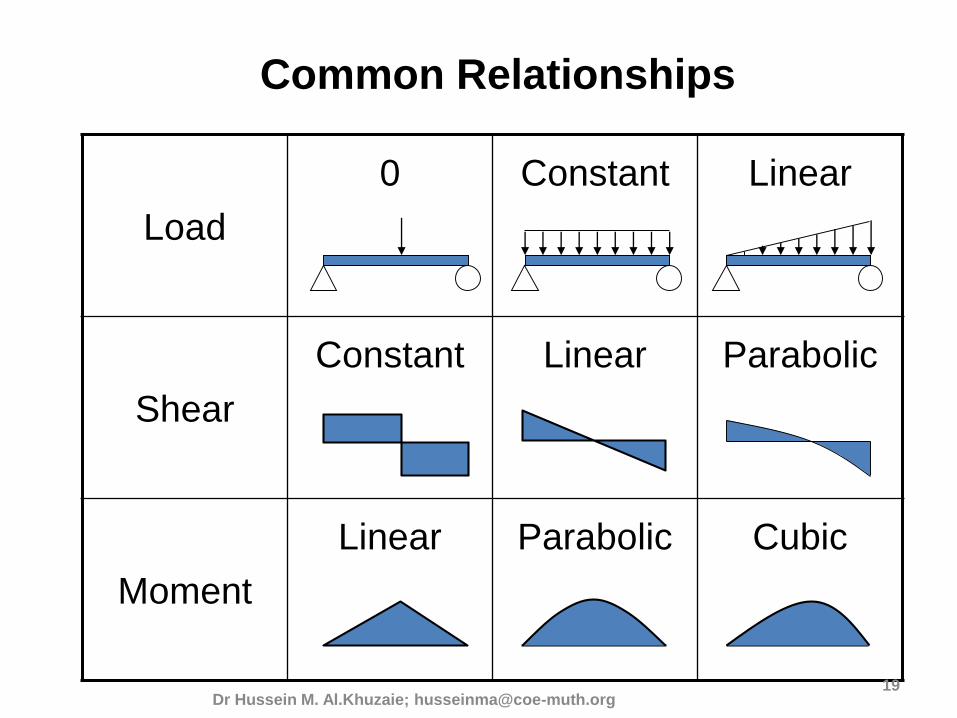
Load
0 Constant Linear
Shear
Constant Linear Parabolic
Moment
Linear Parabolic Cubic
Dr Hussein M. Al.Khuzaie; [email protected]
Common Relationships
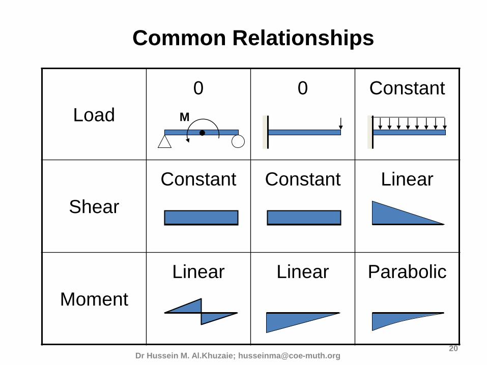
Load
0 0 Constant
Shear
Constant Constant Linear
Moment
Linear Linear Parabolic
Dr Hussein M. Al.Khuzaie; [email protected]
Common Relationships
M

Example: Draw Shear & Moment diagrams for the following beam
Dr Hussein M. Al.Khuzaie;
3 m 1 m1 m
12 kN 8 kNA C
B
D
RA = 7 kN RC = 13 kN
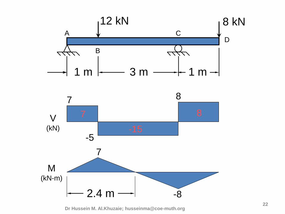
3 m 1 m1 m
12 kNA C
B
D
V(kN)
M(kN-m)
7
-5
8
8 kN
7
-15
8
7
-82.4 m
Dr Hussein M. Al.Khuzaie; [email protected]
Dr Hussein M. Al.Khuzaie; [email protected]
23
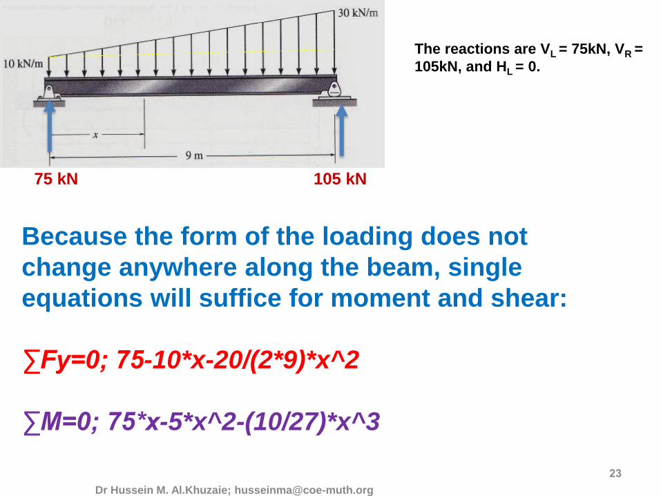
Because the form of the loading does not
change anywhere along the beam, single
equations will suffice for moment and shear:
∑Fy=0; 75-10*x-20/(2*9)*x^2
∑M=0; 75*x-5*x^2-(10/27)*x^3
The reactions are VL = 75kN, VR =
105kN, and HL = 0.
75 kN 105 kN

Dr Hussein M. Al.Khuzaie; [email protected]
-105
-85
-65
-45
-25
-5
15
35
55
75
0 1 2 3 4 5 6 7 8 9
Shear Diagram
0
20
40
60
80
100
120
140
160
180
200
220
0 1 2 3 4 5 6 7 8 9
Shear and
moment are
plotted :
Dr Hussein M. Al.Khuzaie; husseinma@coe-
muth.org25
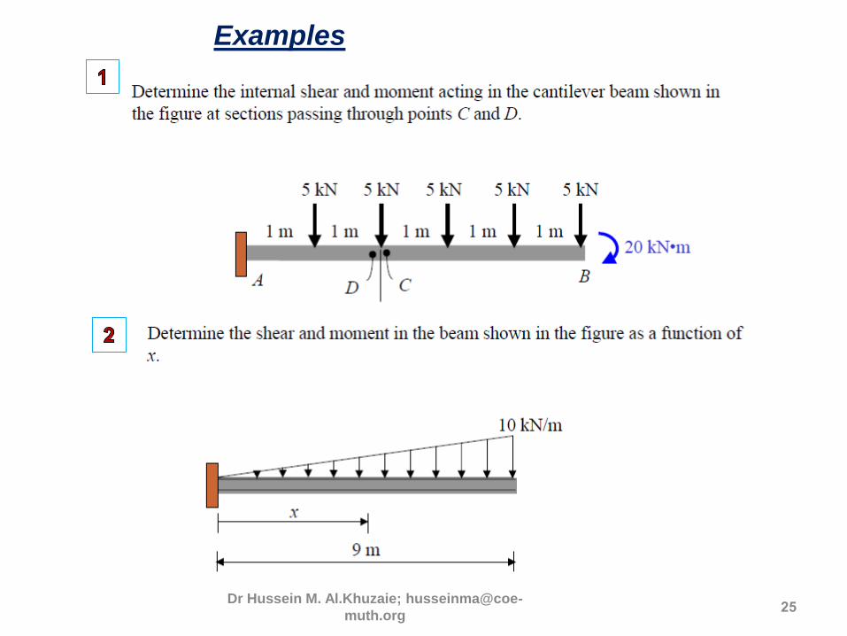
Examples

Dr Hussein M. Al.Khuzaie; husseinma@coe-
muth.org 26
Dr Hussein M. Al.Khuzaie; [email protected] 27
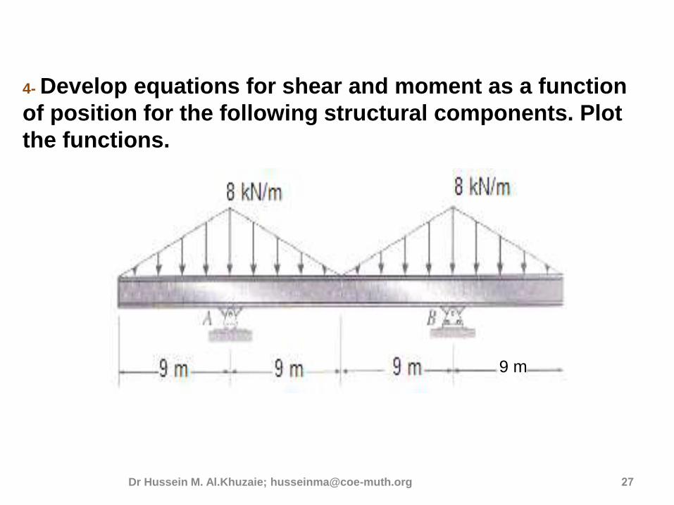
4- Develop equations for shear and moment as a function
of position for the following structural components. Plot
the functions.
9 m