4-/8-port sip internet telephony gateway · 4-/8-port sip internet telephony gateway vgw-x10 series...
TRANSCRIPT
4/8-Port SIP Internet Telephony Gateway VGW-x10 Series
VGW-x10 Series
4-/8-Port SIP Internet
Telephony Gateway
4/8-Port SIP Internet Telephony Gateway VGW-x10 Series
Copyright
Copyright© 2018 by PLANET Technology Corp. All rights reserved. No part of this publication may be
reproduced, transmitted, transcribed, stored in a retrieval system, or translated into any language or
computer language, in any form or by any means, electronic, mechanical, magnetic, optical, chemical,
manual or otherwise, without the prior written permission of PLANET. PLANET makes no representations
or warranties, either expressed or implied, with respect to the contents hereof and specifically disclaims
any warranties, merchantability or fitness for any particular purpose. Any software described in this
manual is sold or licensed "as is". Should the programs prove defective following their purchase, the
buyer (and not this company, its distributor, or its dealer) assumes the entire cost of all necessary
servicing, repair, and any incidental or consequential damages resulting from any defect in the software.
Further, this company reserves the right to revise this publication and to make changes from time to time
in the contents hereof without obligation to notify any person of such revision or changes. All brand and
product names mentioned in this manual are trademarks and/or registered trademarks of their respective
holders.
Disclaimer
PLANET Technology does not warrant that the hardware will work properly in all environments
and applications, and makes no warranty and representation, either implied or expressed, with
respect to the quality, performance, merchantability, or fitness for a particular purpose.
PLANET has made every effort to ensure that this User’s Manual is accurate; PLANET
disclaims liability for any inaccuracies or omissions that may have occurred. Information in this
User’s Manual is subject to change without notice and does not represent a commitment on
the part of PLANET. PLANET assumes no responsibility for any inaccuracies that may be
contained in this User’s Manual. PLANET makes no commitment to update or keep current the
information in this User’s Manual, and reserves the right to make improvements in this User’s
Manual and/or to the products described in this User’s Manual, at any time without notice. If
you find information in this manual that is incorrect, misleading, or incomplete, we would
appreciate your comments and suggestions.
Trademarks
The PLANET logo is a trademark of PLANET Technology. This documentation may refer to
numerous hardware and software products by their trade names. In most, if not all cases,
these designations are claimed as trademarks or registered trademarks by their respective
companies.
CE Mark Warning
This is a class B device, in a domestic environment; this product may cause radio interference,
in which case the user may be required to take adequate measures.
4/8-Port SIP Internet Telephony Gateway VGW-x10 Series
FCC Interference Statement
This equipment has been tested and found to comply with the limits for a Class B digital device,
pursuant to Part 15 of FCC Rules. These limits are designed to provide reasonable protection
against harmful interference in a residential installation. This equipment generates, uses, and
can radiate radio frequency energy and, if not installed and used in accordance with the
instructions, may cause harmful interference to radio communications. However, there is no
guarantee that interference will not occur in a particular installation. If this equipment does
cause harmful interference to radio or television reception, which can be determined by turning
the equipment off and on, the user is encouraged to try to correct the interference by one or
more of the following measures:
1. Reorient or relocate the receiving antenna.
2. Increase the separation between the equipment and receiver.
3. Connect the equipment into an outlet on a circuit different from that to which the receiver is
connected.
4. Consult the dealer or an experienced radio technician for help.
FCC Caution
To assure continued compliance, for example, use only shielded interface cables when
connecting to computer or peripheral devices. Any changes or modifications not expressly
approved by the party responsible for compliance could void the user’s authority to operate the
equipment. This device complies with Part 15 of the FCC Rules. Operation is subject to the
following two conditions: (1) This device may not cause harmful interference, and (2) this
device must accept any interference received, including interference that may cause undesired
operation.
R&TTE Compliance Statement
This equipment complies with all the requirements of DIRECTIVE 1999/5/EC OF THE
EUROPEAN PARLIAMENT AND THE COUNCIL OF 9 March 1999 on radio equipment and
telecommunication terminal Equipment, and the mutual recognition of their conformity
(R&TTE). The R&TTE Directive repeals and replaces in the directive 98/13/EEC
(Telecommunications Terminal Equipment and Satellite Earth Station Equipment) as of April 8,
2000.
WEEE Caution
To avoid the potential effects on the environment and human health as a result of
the presence of hazardous substances in electrical and electronic equipment, end
users of electrical and electronic equipment should understand the meaning of the
crossed-out wheeled bin symbol. Do not dispose of WEEE as unsorted municipal
waste and have to collect such WEEE separately.
4-/8-Port SIP Internet Telephony Gateway VGW-x10 Series
Page I
Contents
Chapter 1 Product Introduction ............................................................................................................ 1
1.1 Product Description ......................................................................................................... 1
1.2 Product Features ............................................................................................................. 2
1.3 Functional Specifications ................................................................................................ 3
1.4 Physical Specifications ................................................................................................... 4
Chapter 2 Installation Preparation ...................................................................................................... 7
2.1 Standard Packing Contents ........................................................................................... 7
2.1.1 Warning .................................................................................................................... 7
2.1.2 Installation Conditions ............................................................................................. 7
2.2 Device installation ............................................................................................................ 8
2.2.1 Fixed to the plane ..................................................................................................... 8
2.3 Cable connection ............................................................................................................. 8
2.3.1 Common connection ................................................................................................ 8
2.3.2 Network topology graph .......................................................................................... 8
2.3.3 Cascade Connection ................................................................................................. 9
2.4 Installation check ........................................................................................................... 10
Chapter 3 UI Introduction .................................................................................................................. 11
3.1 Preparation ..................................................................................................................... 11
3.1.1 Factory parameters ................................................................................................ 11
3.1.2 Login conditions ..................................................................................................... 12
3.2 Login ................................................................................................................................ 12
3.3 Status ............................................................................................................................... 13
3.3.1 Device Info .............................................................................................................. 13
3.3.2 POTS Info ................................................................................................................ 14
3.3.3 Network Info .......................................................................................................... 14
3.4 Fast configuration .......................................................................................................... 15
3.4.1 WAN configuration ................................................................................................. 15
3.4.2 SIP account configuration ....................................................................................... 16
3.4.3 SIP server configuration ......................................................................................... 16
Chapter 4 Detailed Configuration ...................................................................................................... 17
4.1 Network settings ............................................................................................................ 17
4.1.1 WAN settings .......................................................................................................... 17
4.1.2 LAN settings ............................................................................................................ 20
4.1.3 VLAN settings ......................................................................................................... 20
4.1.4 QoS settings ............................................................................................................ 21
4.1.5 NAT settings ............................................................................................................ 21
4.2 Application ....................................................................................................................... 22
4.2.1 Voice Application .................................................................................................... 22
4.2.2 Fax application........................................................................................................ 24
4-/8-Port SIP Internet Telephony Gateway VGW-x10 Series
Page II
4.2.3 SIP services basic configuration.............................................................................. 25
4.2.4 SIP advanced settings ............................................................................................. 26
4.2.5 SIP blacklist and whitelist (VGW-810FS only) ......................................................... 28
4.2.6 Call routing ............................................................................................................. 29
4.2.7 Global settings ........................................................................................................ 31
4.3 Security............................................................................................................................ 33
4.4 Management ................................................................................................................... 34
4.4.1 User management .................................................................................................. 34
4.4.2 Config backup ......................................................................................................... 35
4.4.3 Reset ....................................................................................................................... 36
4.4.4 Reboot .................................................................................................................... 36
4.4.5 System log .............................................................................................................. 37
4.4.6 Device information (VGW-810FS only) ................................................................... 38
Chapter 5 Examples ........................................................................................................................... 39
5.1 FXS business ................................................................................................................. 39
5.1.1 Multi-party conferencing ....................................................................................... 40
5.1.2 Consulting and blind transfer business .................................................................. 41
5.1.3 Call waiting service ................................................................................................. 42
5.1.4 Ringing group ......................................................................................................... 43
5.1.5 Point to Point function ........................................................................................... 44
5.2 System update ............................................................................................................... 45
Chapter 6 FAQs .................................................................................................................................. 46
6.1 CLI maintenance tools .................................................................................................. 46
6.1.1 Telnet login ............................................................................................................. 46
6.1. 2 Serial port login ..................................................................................................... 47
6.1.3 CLI instruction use .................................................................................................. 49
6.1.4 Troubleshooting ..................................................................................................... 50
4-/8-Port SIP Internet Telephony Gateway VGW-x10 Series
Page 1
Chapter 1 Product Introduction
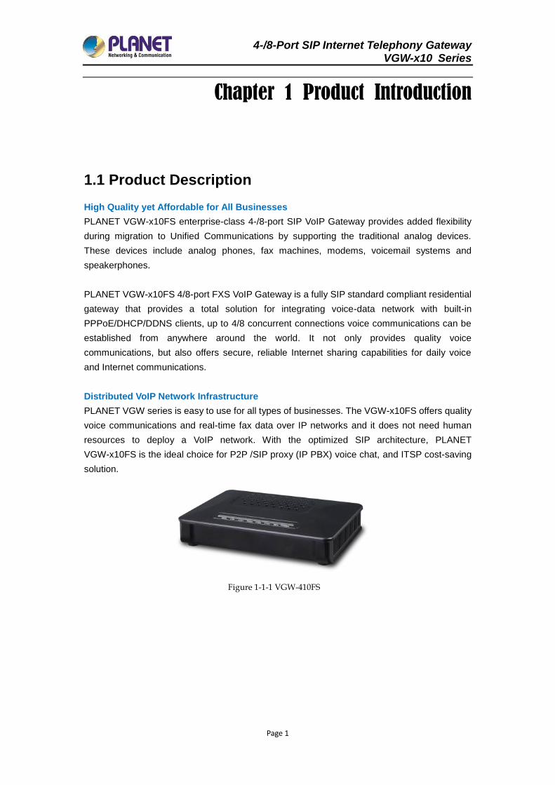
1.1 Product Description
High Quality yet Affordable for All Businesses
PLANET VGW-x10FS enterprise-class 4-/8-port SIP VoIP Gateway provides added flexibility
during migration to Unified Communications by supporting the traditional analog devices.
These devices include analog phones, fax machines, modems, voicemail systems and
speakerphones.
PLANET VGW-x10FS 4/8-port FXS VoIP Gateway is a fully SIP standard compliant residential
gateway that provides a total solution for integrating voice-data network with built-in
PPPoE/DHCP/DDNS clients, up to 4/8 concurrent connections voice communications can be
established from anywhere around the world. It not only provides quality voice
communications, but also offers secure, reliable Internet sharing capabilities for daily voice
and Internet communications.
Distributed VoIP Network Infrastructure
PLANET VGW series is easy to use for all types of businesses. The VGW-x10FS offers quality
voice communications and real-time fax data over IP networks and it does not need human
resources to deploy a VoIP network. With the optimized SIP architecture, PLANET
VGW-x10FS is the ideal choice for P2P /SIP proxy (IP PBX) voice chat, and ITSP cost-saving
solution.
Figure 1-1-1 VGW-410FS

4-/8-Port SIP Internet Telephony Gateway VGW-x10 Series
Page 2
Figure 1-1-2 VGW-810FS
1.2 Product Features
SIP Applications
IETF SIP RFC3261 compliance
4-/8-line FXS connects to analog phone set or PABX
ITU-T G.711 A-law, G.711 μ-law, G.723.1 and G.729 voice coding
In-band / out of band DTMF (RFC4733, RFC2833 / SIP INFO)
Echo cancellation exceeding ITU-T G.165/G.168-2002, up to 128ms tail length
Internet Features
SIP DDoS attack prevention
Supports NAT and Firewall
Supports DHCP server / client
Supports VLAN and QoS: DSCP, TOS (RFC 791, 1394)
Call Features
Supports peer to peer dialing
Supports STUN NAT Traversal
Supports black list and white list Caller ID recognition DTMF and FSK
T.30 transparency, T.30 bypass, and T.38 fax
Multi-party conferencing, call forward, call waiting, hot-line call, DND (Do Not Disturb) and
alarm clock
4-/8-Port SIP Internet Telephony Gateway VGW-x10 Series
Page 3
1.3 Functional Specifications
Product VGW-410FS VGW-810FS
Hardware
WAN 1 x 10/100BASE-TX RJ45 port
LAN 1 x 10/100BASE-TX RJ45 port
Voice 4 x RJ11 connection (8 x foreign
exchange station)
8 x RJ11 connection (8 x foreign
exchange station)
Telephone Wire Transmission
Distance < 1000 m
Connectors
Two 10/100BASE-TX RJ45
Ethernet ports
Four RJ11 ports
DC power jack
One console port
Two 10/100BASE-TX RJ45
Ethernet ports
Eight RJ11 ports
DC power jack
Weight 205 g 565 g
Dimensions (W x D x H) 160 x 115 x 30 mm 267 x 196 x 40 mm
Power Requirements 12V DC, 1.0A 12V DC, 2.0A
Protocols and Standard
Data Networking
TCP/IP, UDP(RFC 793/768), RTP/RTCP(RFC 1889/1890), ARP,
FTP/TFTP, HTTP, HTTPS, Telnet, ICMP, NTP/SNTP, DHCP
Server/Client
IPv4
Static IP
PPPoE Client
DHCP Server, LAN port
DHCP Client (RFC 2131), WAN port, NAT server (RFC 1631)
Firewall
SIP attack prevention
VLAN
QoS: DSCP, TOS (RFC 791, 1394)
VoIP
IETF SIP RFC3261 compliance
Primary and secondary SIP server to automatic switch
Voice coding: ITU-T G.711 A-law, G.711 μ-law, G.723.1(5.3K/6.3Kbit/s),
G.729 and auto-negotiate with call agent
Echo cancellation exceeding ITU-T G.165/G.168-2002, up to 128ms
tail length
10 ~ 180ms adjustable delay jitter
DSP gain can be adjusted, -5dB ~ + 10dB
In-band / out of band DTMF (RFC4733, RFC2833 / SIP INFO)
Integrate heartbeat function
Supports active and standby call agent
Supports VGW series expanding (One master and two slaves)
Supports local polyphonic ringtone
Supports call routing and digit map
4-/8-Port SIP Internet Telephony Gateway VGW-x10 Series
Page 4
Supports caller ID, DTMF and FSK
Supports Dial route IP; calls between two VGWs are supported without
a SIP server
Supports multi-party conferencing, call forward, call waiting, hot-line
call, DND (Do Not Disturb) and alarm clock
Supports high/low speed fax/modem. T.30 transparency, T.30 bypass,
and T.38 fax
Management
Multilingual Web user interface
3 levels of user access right with password protection with a different
Web language (administrator, supervisor and user)
Configuration backup/restore
Reset to factory default
Environments
Operating Temperature -10 ~ 50 degrees C
Operating Humidity 10%~90% relative humidity, non-condensing
Emission CE, FCC, RoHS
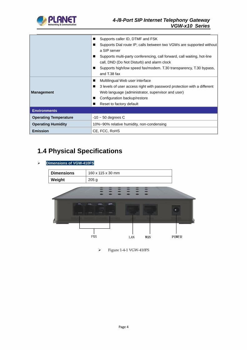
1.4 Physical Specifications
Dimensions of VGW-410FS
Dimensions 160 x 115 x 30 mm
Weight 205 g
Figure 1-4-1 VGW-410FS
4-/8-Port SIP Internet Telephony Gateway VGW-x10 Series
Page 5
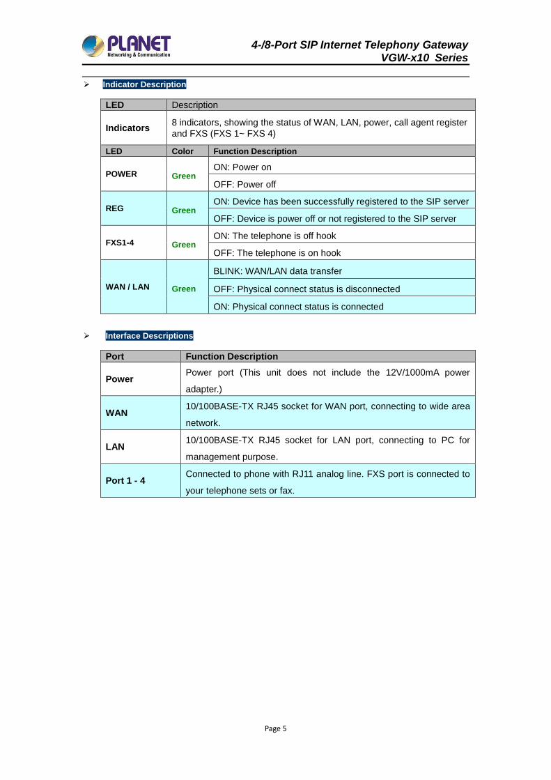
Indicator Description
LED Description
Indicators 8 indicators, showing the status of WAN, LAN, power, call agent register
and FXS (FXS 1~ FXS 4)
LED Color Function Description
POWER Green ON: Power on
OFF: Power off
REG Green ON: Device has been successfully registered to the SIP server
OFF: Device is power off or not registered to the SIP server
FXS1-4 Green ON: The telephone is off hook
OFF: The telephone is on hook
WAN / LAN Green
BLINK: WAN/LAN data transfer
OFF: Physical connect status is disconnected
ON: Physical connect status is connected
Interface Descriptions
Port Function Description
Power Power port (This unit does not include the 12V/1000mA power
adapter.)
WAN 10/100BASE-TX RJ45 socket for WAN port, connecting to wide area
network.
LAN 10/100BASE-TX RJ45 socket for LAN port, connecting to PC for
management purpose.
Port 1 - 4 Connected to phone with RJ11 analog line. FXS port is connected to
your telephone sets or fax.
4-/8-Port SIP Internet Telephony Gateway VGW-x10 Series
Page 6
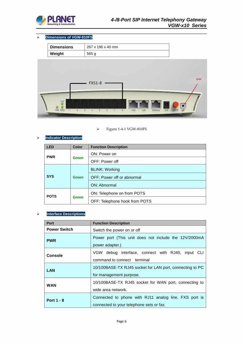
Dimensions of VGW-810FS
Dimensions 267 x 196 x 40 mm
Weight 565 g
Figure 1-4-1 VGW-810FS
Indicator Description
LED Color Function Description
PWR Green ON: Power on
OFF: Power off
SYS Green
BLINK: Working
OFF: Power off or abnormal
ON: Abnormal
POTS Green ON: Telephone on from POTS
OFF: Telephone hook from POTS
Interface Descriptions
Port Function Description
Power Switch Switch the power on or off
PWR Power port (This unit does not include the 12V/2000mA
power adapter.)
Console VGW debug interface, connect with RJ45, input CLI
command to connect terminal
LAN 10/100BASE-TX RJ45 socket for LAN port, connecting to PC
for management purpose.
WAN 10/100BASE-TX RJ45 socket for WAN port, connecting to
wide area network.
Port 1 - 8 Connected to phone with RJ11 analog line. FXS port is
connected to your telephone sets or fax.
4-/8-Port SIP Internet Telephony Gateway VGW-x10 Series
Page 7
Chapter 2 Installation Preparation
2.1 Standard Packing Contents
Thank you for purchasing PLANET Internet Telephony Gateway system, the VGW-400 series. This
Quick Installation Guide will introduce how to finish the basic setting of connecting the web
management interface and the Internet. Open the box of the Internet Telephony Gateway system and
carefully unpack it. The box should contain the following items:
VGW-x10 Series x 1
Quick Installation Guide x 1
Power Adapter x 1 (12V)
RJ45 x 1 (VGW-810 series only)
If any of the above items are damaged or missing, please contact your dealer immediately.
2.1.1 Warning
To avoid device damage caused by improper use and personal injury, please comply with the
following precautions:
Don’t install it on the wet place.
Put the device on a clean, flat, sturdy bench top.
Make sure that supplied power voltage is the same as that of the device required.
It is forbidden to open the device’s panel without permission.
Before cleaning the device, make sure that power is off. Don’t use liquid to clean the
device.
2.1.2 Installation Conditions
The VGW-x10 series must be installed indoors, and also the following items must be had:
Basic items needed include power supply, Internet cable and PC.
Single phase three core power socket like AC socket is required. And make sure that the
device power must be connected to the ground.
Enough space for heat dissipation
Working temperature is -10℃~ 50℃, humidity of 10% to 90%
The electromagnetic interference of nearby broadcasting station, radar transmitters and
high frequency, high power device, etc. must be avoided.
Connecting cable usually is installed indoors. If the cable is installed outdoors, surge
protection measurement must be taken into consideration.
4-/8-Port SIP Internet Telephony Gateway VGW-x10 Series
Page 8
2.2 Device installation
This chapter describes two common installation methods. After device’s install spot is
selected, phone line, RJ45 cable and power cable must be connected.
2.2.1 Fixed to the plane
Put the VGW-x10 series on a clean, flat, steady bench top, and follow the steps below:
Ensure workplace is flat and stable.
Keep certain space for all sides of the device for heat dissipation.
Don’t place anything on it.
2.3 Cable connection
2.3.1 Common connection
The downlink is made through LAN using RJ45 cable to connect with user PC, switch or hub,
while the uplink is made through WAN using RJ45 cable to connect with Ethernet (such as ONU)
or ADSL modem. RJ11 is used to connect user telephone and VGW’s FXS port.
Before you push the power button, make sure that all cables have been connected.
It is strong recommended to use a neutral point power connector, which has a
single-phase three-wire power or multi-purpose PC power socket. In this case, power
has grounded outlet that assure operator’s safety. Do not use extension cords.
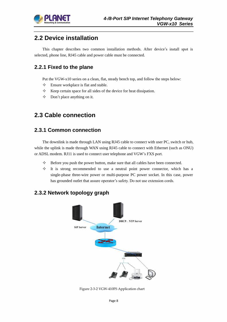
2.3.2 Network topology graph
Figure 2-3-2 VGW-410FS Application chart
4-/8-Port SIP Internet Telephony Gateway VGW-x10 Series
Page 9
Uplink via WAN port connect to xDSL (Cable) Modem as proxy server.
Downlink via LAN port connect to user PC, switch and hub.
According to the LAN environment, select corresponding DHCP, PPPoE or static IP to
connect to the internet.
FXS port can direct connect to telephone, fax and POS terminal.
Support power survival function. When the device power supply is interrupted, the
upper and lower port circuits connect directly.
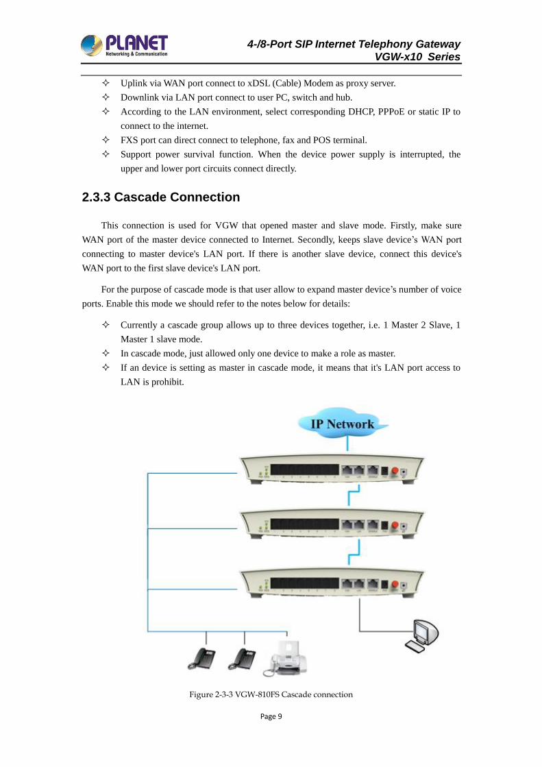
2.3.3 Cascade Connection
This connection is used for VGW that opened master and slave mode. Firstly, make sure
WAN port of the master device connected to Internet. Secondly, keeps slave device’s WAN port
connecting to master device's LAN port. If there is another slave device, connect this device's
WAN port to the first slave device's LAN port.
For the purpose of cascade mode is that user allow to expand master device’s number of voice
ports. Enable this mode we should refer to the notes below for details:
Currently a cascade group allows up to three devices together, i.e. 1 Master 2 Slave, 1
Master 1 slave mode.
In cascade mode, just allowed only one device to make a role as master.
If an device is setting as master in cascade mode, it means that it's LAN port access to
LAN is prohibit.
Figure 2-3-3 VGW-810FS Cascade connection
4-/8-Port SIP Internet Telephony Gateway VGW-x10 Series
Page 10
VGW cascade mode of start and stop,See "4.1.1 WAN port configuration settings in
cascade".
2.4 Installation check
In this step, we should check VGW device when power is on. But before this, you should
ensure cable connection and power connections are done by referring to the following steps:
Check the power indicator (PWR) whether is on or not. If so, it indicates that device’s
power is ready, otherwise please check the connection of the power plug or power
adaptor.
When LAN or WAN port LED is blinking, it indicates that network is ready. Otherwise,
check network connection.
When device’s (SYS) LED is blinking, at the same time when you pick up the phone
and the phone port LED is on. It proves telephone port is ready, otherwise check the
telephone connection.
4-/8-Port SIP Internet Telephony Gateway VGW-x10 Series
Page 11
Chapter 3 UI Introduction
After finishing the basic connection configuration, you can use its basic function. In order to
satisfy individual service requirements, this chapter provides you with parameter modification
and individual configuration description.
VoIP Gateway can be configured with your web browser. A web browser is included as a
standard application in the following operating systems: Windows 2003/NT/XP/7/8/10/Me, MAC,
Linux, etc. The product provides a very easy and user-friendly interface for configuration.
Web configuration interface may vary with different software versions.
Administrator-level and general user-level configuration interfaces display differently.
The following section is an example of an administrator-level description.
3.1 Preparation
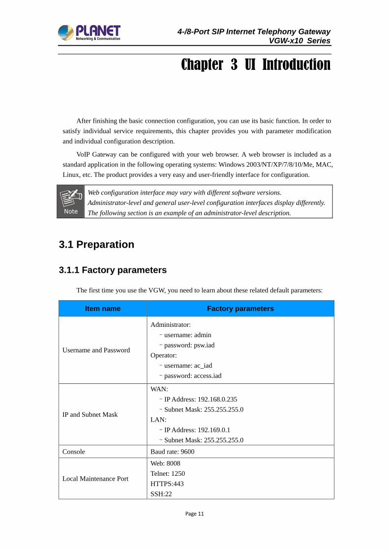
3.1.1 Factory parameters
The first time you use the VGW, you need to learn about these related default parameters:
Item name Factory parameters
Username and Password
Administrator:
–username: admin
–password: psw.iad
Operator:
–username: ac_iad
–password: access.iad
IP and Subnet Mask
WAN:
–IP Address: 192.168.0.235
–Subnet Mask: 255.255.255.0
LAN:
–IP Address: 192.169.0.1
–Subnet Mask: 255.255.255.0
Console Baud rate: 9600
Local Maintenance Port
Web: 8008
Telnet: 1250
HTTPS:443
SSH:22
4-/8-Port SIP Internet Telephony Gateway VGW-x10 Series
Page 12
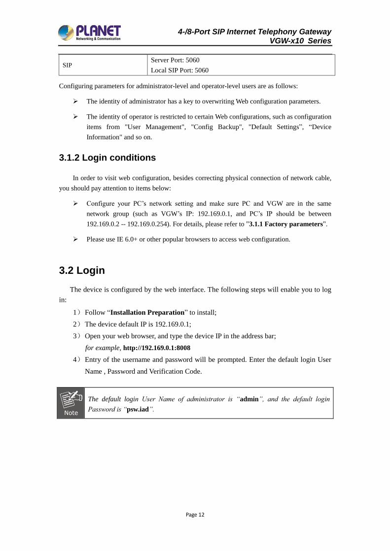
SIP Server Port: 5060
Local SIP Port: 5060
Configuring parameters for administrator-level and operator-level users are as follows:
The identity of administrator has a key to overwriting Web configuration parameters.
The identity of operator is restricted to certain Web configurations, such as configuration
items from "User Management", "Config Backup", "Default Settings”, “Device
Information" and so on.
3.1.2 Login conditions
In order to visit web configuration, besides correcting physical connection of network cable,
you should pay attention to items below:
Configure your PC’s network setting and make sure PC and VGW are in the same
network group (such as VGW’s IP: 192.169.0.1, and PC’s IP should be between
192.169.0.2 -- 192.169.0.254). For details, please refer to "3.1.1 Factory parameters".
Please use IE 6.0+ or other popular browsers to access web configuration.
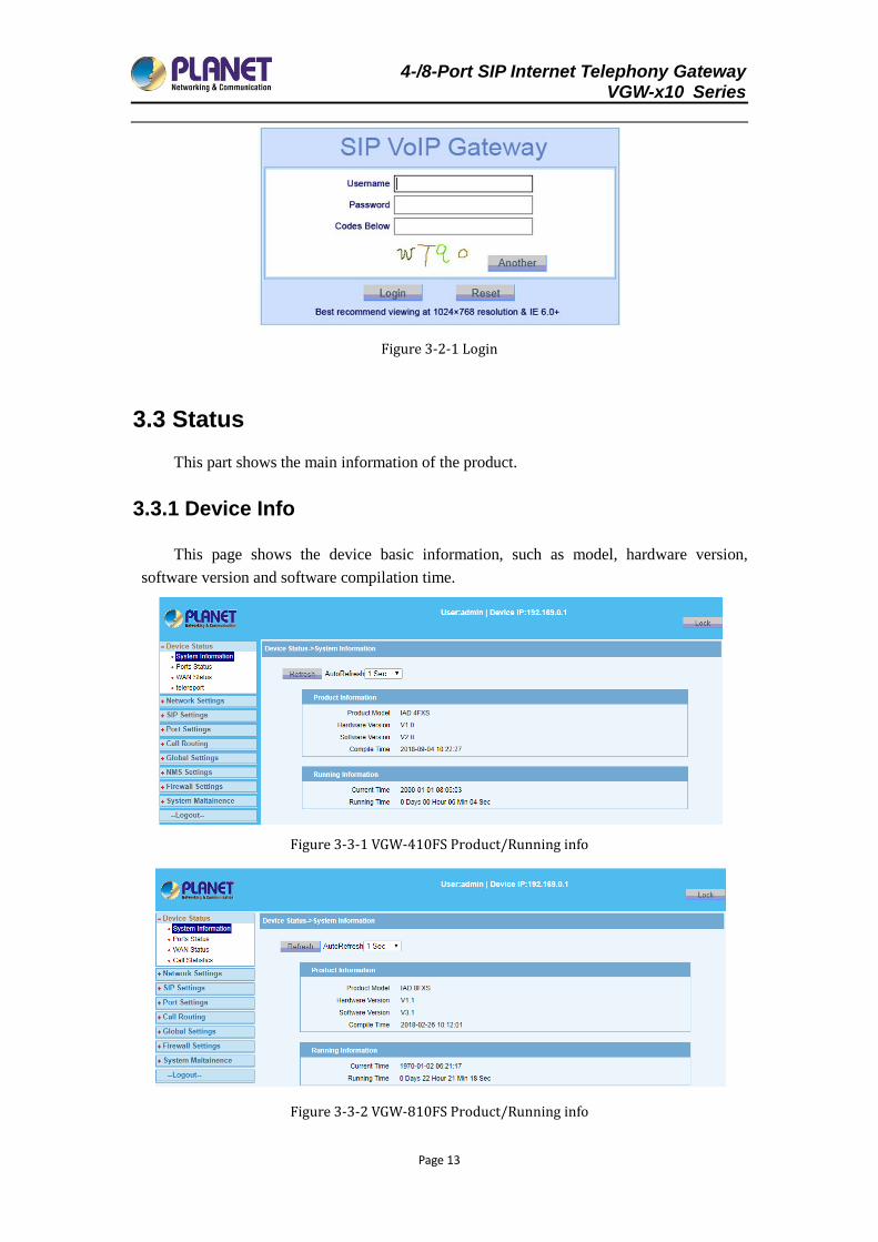
3.2 Login
The device is configured by the web interface. The following steps will enable you to log
in:
1) Follow “Installation Preparation” to install;
2) The device default IP is 192.169.0.1;
3) Open your web browser, and type the device IP in the address bar;
for example, http://192.169.0.1:8008
4) Entry of the username and password will be prompted. Enter the default login User
Name , Password and Verification Code.
The default login User Name of administrator is “admin”, and the default login
Password is “psw.iad”.
4-/8-Port SIP Internet Telephony Gateway VGW-x10 Series
Page 13
Figure 3-2-1 Login
3.3 Status
This part shows the main information of the product.
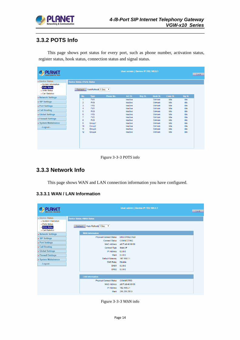
3.3.1 Device Info
This page shows the device basic information, such as model, hardware version,
software version and software compilation time.
Figure 3-3-1 VGW-410FS Product/Running info
Figure 3-3-2 VGW-810FS Product/Running info
4-/8-Port SIP Internet Telephony Gateway VGW-x10 Series
Page 14
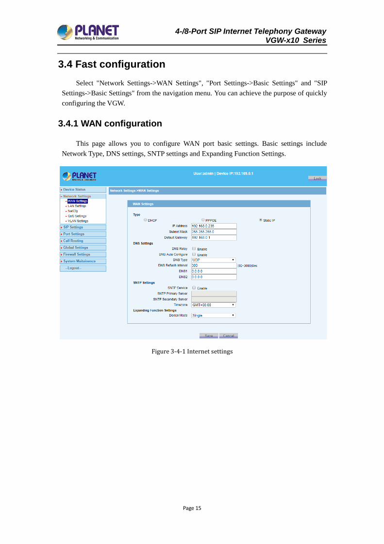
3.3.2 POTS Info
This page shows port status for every port, such as phone number, activation status,
register status, hook status, connection status and signal status.
Figure 3-3-3 POTS info
3.3.3 Network Info
This page shows WAN and LAN connection information you have configured.
3.3.3.1 WAN / LAN Information
Figure 3-3-3 WAN info
4-/8-Port SIP Internet Telephony Gateway VGW-x10 Series
Page 15
3.4 Fast configuration
Select "Network Settings->WAN Settings", "Port Settings->Basic Settings" and "SIP
Settings->Basic Settings" from the navigation menu. You can achieve the purpose of quickly
configuring the VGW.
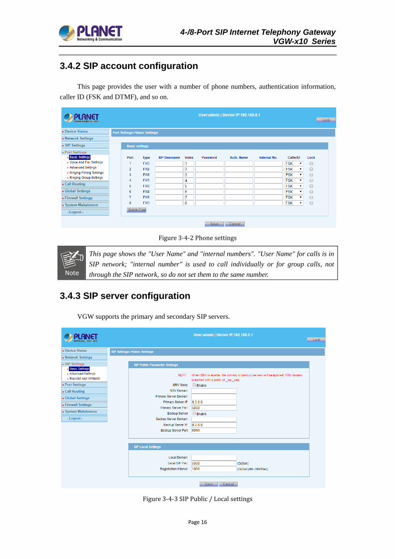
3.4.1 WAN configuration
This page allows you to configure WAN port basic settings. Basic settings include
Network Type, DNS settings, SNTP settings and Expanding Function Settings.
Figure 3-4-1 Internet settings
4-/8-Port SIP Internet Telephony Gateway VGW-x10 Series
Page 16
3.4.2 SIP account configuration
This page provides the user with a number of phone numbers, authentication information,
caller ID (FSK and DTMF), and so on.
Figure 3-4-2 Phone settings
This page shows the "User Name" and "internal numbers". "User Name" for calls is in
SIP network; "internal number" is used to call individually or for group calls, not
through the SIP network, so do not set them to the same number.
3.4.3 SIP server configuration
VGW supports the primary and secondary SIP servers.
Figure 3-4-3 SIP Public / Local settings
4-/8-Port SIP Internet Telephony Gateway VGW-x10 Series
Page 17
Chapter 4 Detailed Configuration
This chapter will introduce how to configure device’s VoIP simply through web, so that
you can configure VGW quickly. This chapter includes the following contents:
Network Settings
Application
Security
Management
4.1 Network settings
4.1.1 WAN settings
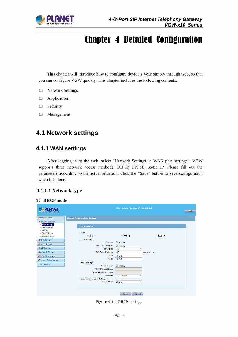
After logging in to the web, select "Network Settings -> WAN port settings". VGW
supports three network access methods: DHCP, PPPoE, static IP. Please fill out the
parameters according to the actual situation. Click the "Save" button to save configuration
when it is done.
4.1.1.1 Network type
1) DHCP mode
Figure 4-1-1 DHCP settings
4-/8-Port SIP Internet Telephony Gateway VGW-x10 Series
Page 18
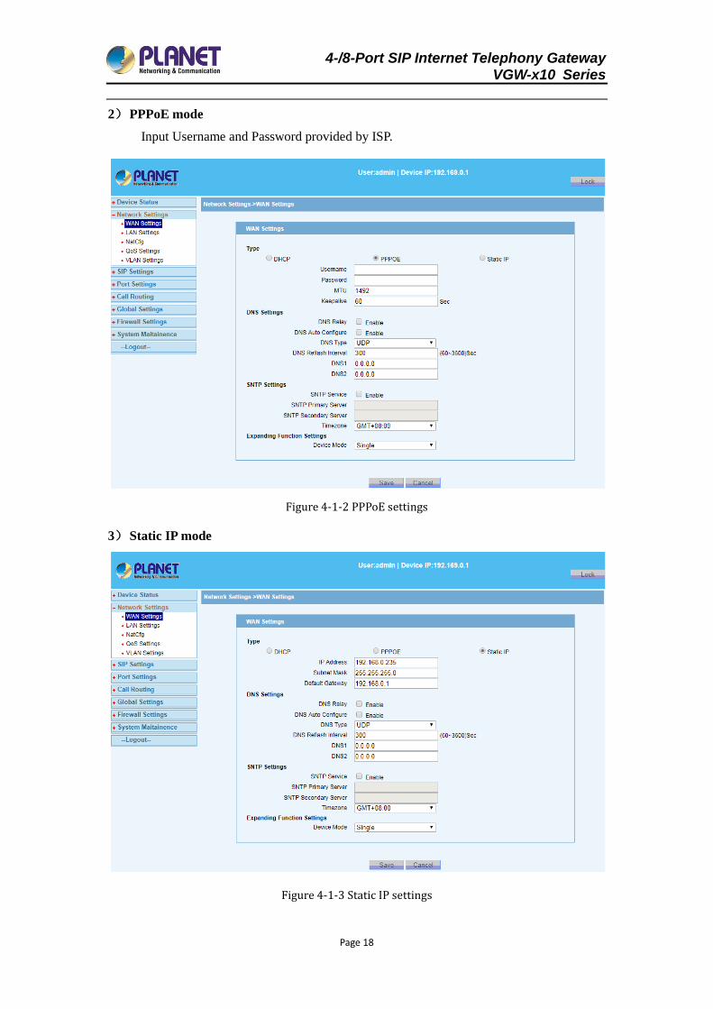
2) PPPoE mode
Input Username and Password provided by ISP.
Figure 4-1-2 PPPoE settings
3) Static IP mode
Figure 4-1-3 Static IP settings
4-/8-Port SIP Internet Telephony Gateway VGW-x10 Series
Page 19
You can select the appropriate network type based on your network conditions from
the three network types.
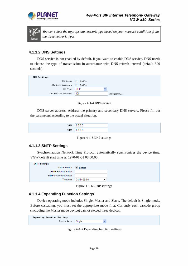
4.1.1.2 DNS Settings
DNS service is not enabled by default. If you want to enable DNS service, DNS needs
to choose the type of transmission in accordance with DNS refresh interval (default 300
seconds).
Figure 4-1-4 DNS service
DNS server address: Address the primary and secondary DNS servers, Please fill out
the parameters according to the actual situation.
Figure 4-1-5 DNS settings
4.1.1.3 SNTP Settings
Synchronization Network Time Protocol automatically synchronizes the device time.
VGW default start time is: 1970-01-01 08:00:00.
Figure 4-1-6 STNP settings
4.1.1.4 Expanding Function Settings
Device operating mode includes Single, Master and Slave. The default is Single mode.
Before cascading, you must set the appropriate mode first. Currently each cascade group
(including the Master mode device) cannot exceed three devices.
Figure 4-1-7 Expanding function settings
4-/8-Port SIP Internet Telephony Gateway VGW-x10 Series
Page 20
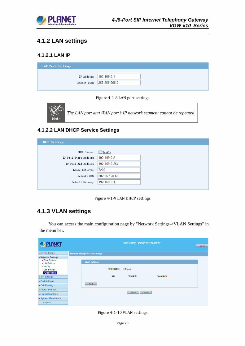
4.1.2 LAN settings
4.1.2.1 LAN IP
Figure 4-1-8 LAN port settings
The LAN port and WAN port’s IP network segment cannot be repeated.
4.1.2.2 LAN DHCP Service Settings
Figure 4-1-9 LAN DHCP settings
4.1.3 VLAN settings
You can access the main configuration page by "Network Settings->VLAN Settings" in
the menu bar.
Figure 4-1-10 VLAN settings
4-/8-Port SIP Internet Telephony Gateway VGW-x10 Series
Page 21
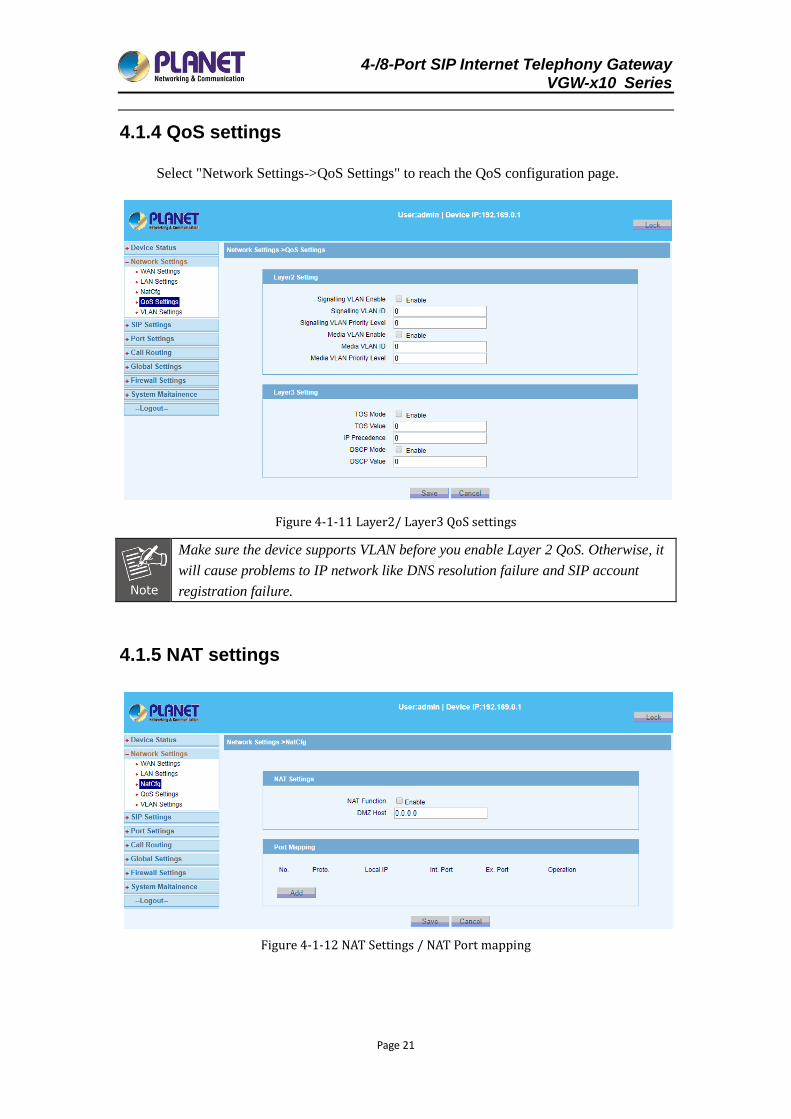
4.1.4 QoS settings
Select "Network Settings->QoS Settings" to reach the QoS configuration page.
Figure 4-1-11 Layer2/ Layer3 QoS settings
Make sure the device supports VLAN before you enable Layer 2 QoS. Otherwise, it
will cause problems to IP network like DNS resolution failure and SIP account
registration failure.
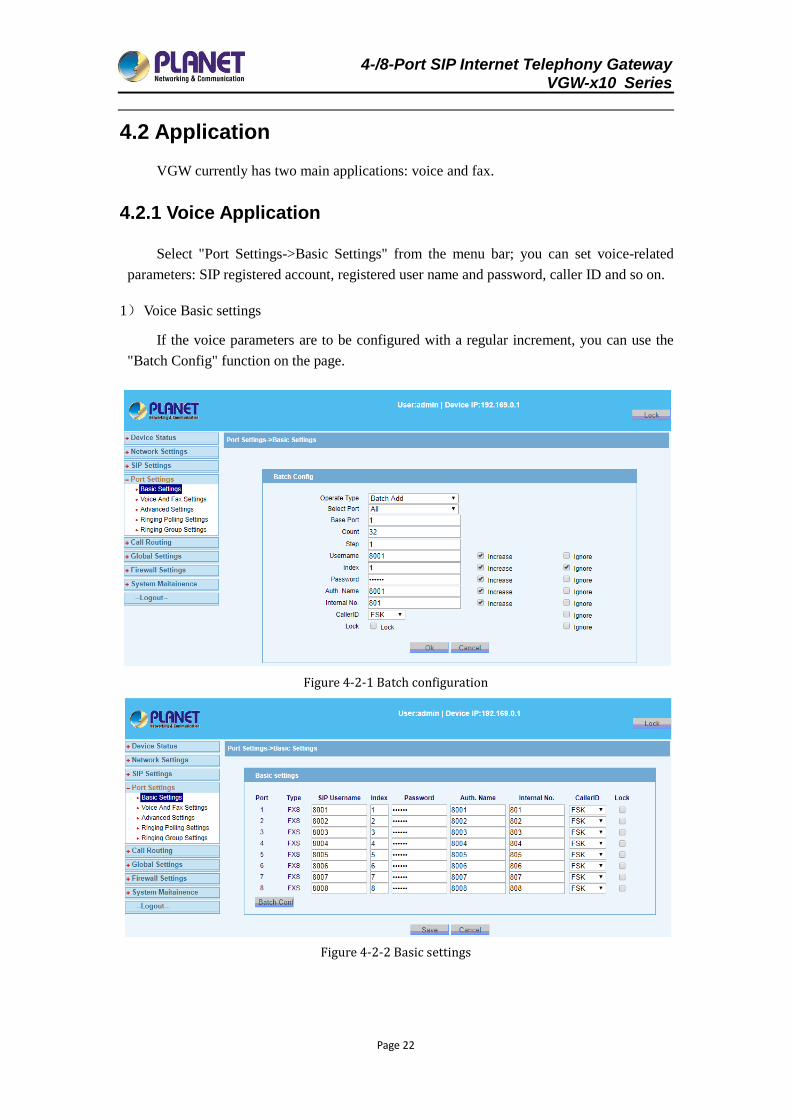
4.1.5 NAT settings
Figure 4-1-12 NAT Settings / NAT Port mapping
4-/8-Port SIP Internet Telephony Gateway VGW-x10 Series
Page 22
4.2 Application
VGW currently has two main applications: voice and fax.
4.2.1 Voice Application
Select "Port Settings->Basic Settings" from the menu bar; you can set voice-related
parameters: SIP registered account, registered user name and password, caller ID and so on.
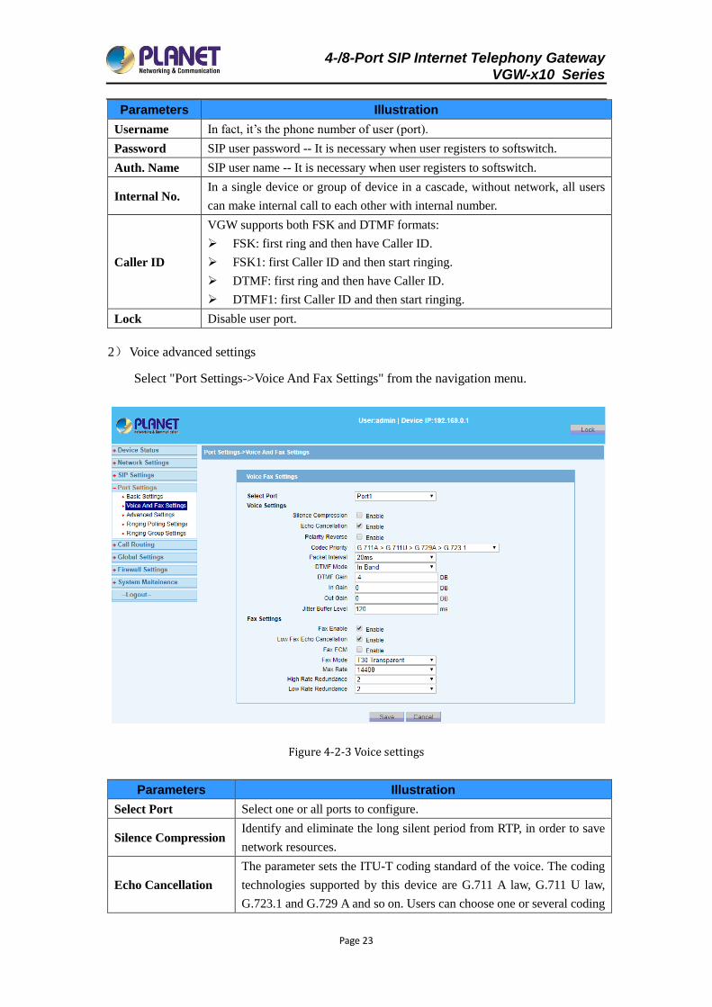
1) Voice Basic settings
If the voice parameters are to be configured with a regular increment, you can use the
"Batch Config" function on the page.
Figure 4-2-1 Batch configuration
Figure 4-2-2 Basic settings
4-/8-Port SIP Internet Telephony Gateway VGW-x10 Series
Page 23
Parameters Illustration
Username In fact, it’s the phone number of user (port).
Password SIP user password -- It is necessary when user registers to softswitch.
Auth. Name SIP user name -- It is necessary when user registers to softswitch.
Internal No. In a single device or group of device in a cascade, without network, all users
can make internal call to each other with internal number.
Caller ID
VGW supports both FSK and DTMF formats:
FSK: first ring and then have Caller ID.
FSK1: first Caller ID and then start ringing.
DTMF: first ring and then have Caller ID.
DTMF1: first Caller ID and then start ringing.
Lock Disable user port.
2) Voice advanced settings
Select "Port Settings->Voice And Fax Settings" from the navigation menu.
Figure 4-2-3 Voice settings
Parameters Illustration
Select Port Select one or all ports to configure.
Silence Compression Identify and eliminate the long silent period from RTP, in order to save
network resources.
Echo Cancellation
The parameter sets the ITU-T coding standard of the voice. The coding
technologies supported by this device are G.711 A law, G.711 U law,
G.723.1 and G.729 A and so on. Users can choose one or several coding
4-/8-Port SIP Internet Telephony Gateway VGW-x10 Series
Page 24
modes, but one of those modes must be chosen as the priority.
Flash It is disabled by default.
Codec Priority Set the size of RTP packages. The larger the value, the larger the RTP
packages and better utilization of network bandwidth.
Packet Interval Disable user port.
DTMF Mode
It is referred to the transfer mode of users pressing the button in the
progress of talk. It can be set in such four modes as In Brand,
RFC2833, RFC2198 and INFO.
DTMF Gain The DTMF gain can be set between -31 and 31 decibels (dB).
In Gain The device allows you to configure the level of the received (input
gain) Tel-to-IP signal and the level of the transmitted (output gain)
IP-to-Tel signal. The gain can be set between -31 and 31 decibels (dB). Out Gain
Jitter Buffer Level Defines the starting jitter capacity of the buffer. (0 msec to 250 msec)
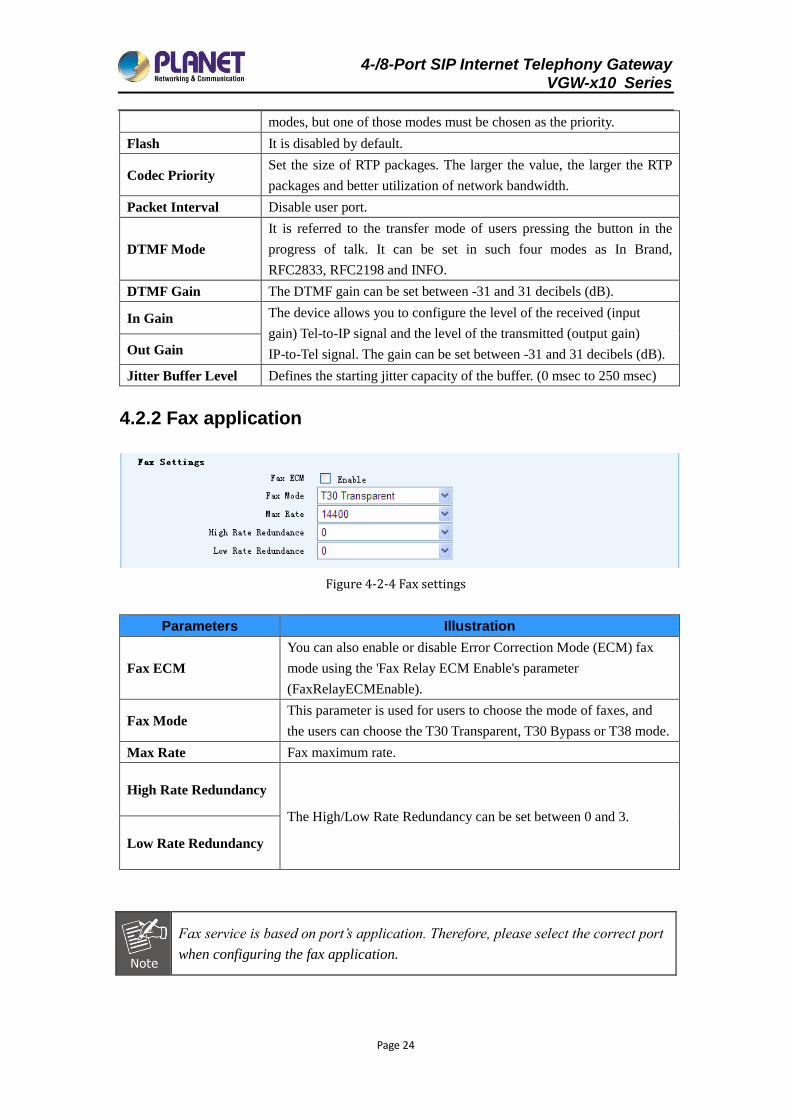
4.2.2 Fax application
Figure 4-2-4 Fax settings
Parameters Illustration
Fax ECM
You can also enable or disable Error Correction Mode (ECM) fax
mode using the 'Fax Relay ECM Enable's parameter
(FaxRelayECMEnable).
Fax Mode This parameter is used for users to choose the mode of faxes, and
the users can choose the T30 Transparent, T30 Bypass or T38 mode.
Max Rate Fax maximum rate.
High Rate Redundancy
The High/Low Rate Redundancy can be set between 0 and 3.
Low Rate Redundancy
Fax service is based on port’s application. Therefore, please select the correct port
when configuring the fax application.
4-/8-Port SIP Internet Telephony Gateway VGW-x10 Series
Page 25
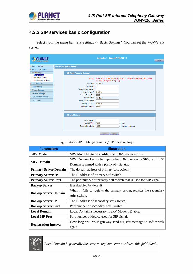
4.2.3 SIP services basic configuration
Select from the menu bar "SIP Settings -> Basic Settings". You can set the VGW's SIP
server.
Figure 4-2-5 SIP Public parameter / SIP Local settings
Parameters Illustration
SRV Mode SRV Mode has to be enable when DNS server is SRV.
SRV Domain SRV Domain has to be input when DNS server is SRV, and SRV
Domain is named with a prefix of _sip_udp.
Primary Server Domain The domain address of primary soft switch.
Primary Server IP The IP address of primary soft switch.
Primary Server Port The port number of primary soft switch that is used for SIP signal.
Backup Server It is disabled by default.
Backup Server Domain When it fails to register the primary server, register the secondary
softs switch.
Backup Server IP The IP address of secondary softs switch.
Backup Server Port Port number of secondary softs switch.
Local Domain Local Domain is necessary if SRV Mode is Enable.
Local SIP Port Port number of device used for SIP signal.
Registration Interval How long will VoIP gateway send register message to soft switch
again.
Local Domain is generally the same as register server or leave this field blank.
4-/8-Port SIP Internet Telephony Gateway VGW-x10 Series
Page 26
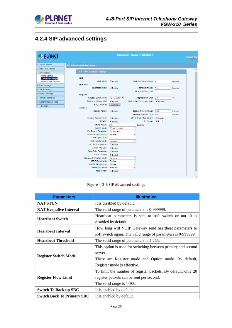
4.2.4 SIP advanced settings
Figure 4-2-6 SIP Advanced settings
Parameters Illustration
NAT STUN It is disabled by default.
NAT Keepalive Interval The valid range of parameters is 0-999999.
Heartbeat Switch Heartbeat parameters is sent to soft switch or not. It is
disabled by default.
Heartbeat Interval How long will VOIP Gateway send heartbeat parameters to
soft switch again. The valid range of parameters is 0-999999.
Heartbeat Threshold The valid range of parameters is 1-255.
Register Switch Mode
This option is used for switching between primary and second
server.
There are Register mode and Option mode. By default,
Register mode is effective.
Register Flow Limit
To limit the number of register packets. By default, only 20
register packets can be sent per second.
The valid range is 1-100.
Switch To Back up SBC It is enabled by default.
Switch Back To Primary SBC It is enabled by default.
4-/8-Port SIP Internet Telephony Gateway VGW-x10 Series
Page 27
Session Update It is disabled by default.
Session Update Interval The time that session will update. It must be greater than
session minimum time.
Session Minimum Time The default value is 90s.
Register Authentication It should be enabled if the soft switch uses SIP DIGIST for
authentication.
SIP URI With User Param
SIP header fields content attributes.
Generally appear in the "From", "To" and "P-Preferred-
Identity". If you enable it, "INVITE" header field "From" and
"To" will carry "user = phone".
PRACK SIP’s extension header field, disabled by default.
"ACK" temporary response message headers.
URI Format
Supports both formats: SIP and TEL
Generally appear in the From, To and P - Preferred - Identity.
SIP:From: "88880009"<sip:[email protected];user=phone>;
TEL :From: <tel:88880009>;
Offline Interval
The interval that VGW initiates registration again after
registration has failed.
Note: It is not a registered retransmission mechanism.
CallerID Mode Specify the origin of caller ID. There are two modes, “From”
header and PPI (P-Prefered-Identity) header.
Fax Bypass Parameter This fax parameter is the used for adapting requirements of a
different soft switch when consulting with opposite side.
Phone Number Format "Normal" and "Escape Character".
User-Agent Value
By default, it is blank. But the value of this field in the SIP
messages is the name of device, otherwise it’s what you filled
in.
Blind Transfer Mode
VGW supports two modes, Normal and Cancel->Refer.
Normal: VGW will send SIP signal by INVITE form when
hook flash in blind transfer.
Cancel->Refer: VGW will send SIP signal by REFER when
hook flash in blind transfer.
Don't Support Reinvite It is disabled by default. VGW will not send INVITE
message when hook flash.
Proxy Authentication Mode The default is general.
"Option" mode is based on heartbeat function. So if you choose this mode,
you must enable Heartbeat Switch. In this mode, VoIP Gateway sends
heartbeat packets both to the primary and secondary server
simultaneously. VGW will try up to 3 times to send heartbeat until primary
server responds. If the primary server responds, device will send
registration request to it. If VGW tries three times continuously with no
4-/8-Port SIP Internet Telephony Gateway VGW-x10 Series
Page 28
response of the primary server during heartbeat threshold time, it will
switch to secondary server.
Once the primary server recovers normal and responds heartbeat
messages, VGW will switch back to it again.
In “Register” mode, whether it is switched or not between primary and
secondary server, it is decided by response of registration or invite
messages. Firstly, VGW sends registration messages to primary server. If
the server doesn't respond for 3 times continuously, VGW will switch to
secondary server. Switching from secondary server to primary is the same
mechanism. When VGW has registered to soft switch for 3 times with no
response of invite messages, VGW will switch to another server. In
"Register" mode, primary and secondary servers are parallel in
relationship, meaning it will only switch when the server gets a breakdown.
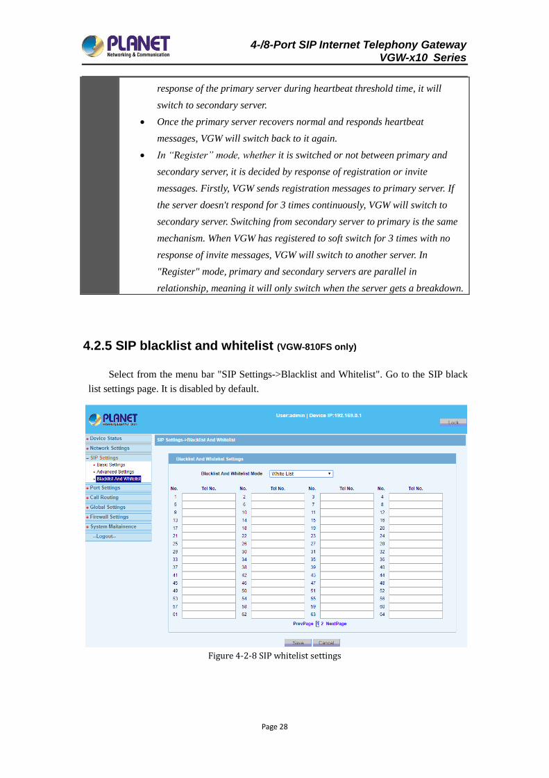
4.2.5 SIP blacklist and whitelist (VGW-810FS only)
Select from the menu bar "SIP Settings->Blacklist and Whitelist". Go to the SIP black
list settings page. It is disabled by default.
Figure 4-2-8 SIP whitelist settings
4-/8-Port SIP Internet Telephony Gateway VGW-x10 Series
Page 29
SIP blacklist and whitelist function is to limit the number of SIP callouts.
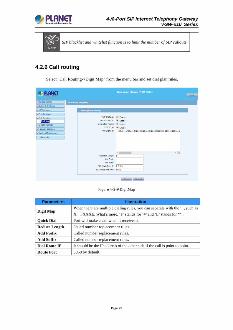
4.2.6 Call routing
Select "Call Routing->Digit Map" from the menu bar and set dial plan rules.
Figure 4-2-9 DigitMap
Parameters Illustration
Digit Map When there are multiple dialing rules, you can separate with the ‘|’, such as
X. | FXXXE. What’s more, ‘F’ stands for ‘#’ and ‘E’ stands for ‘*’.
Quick Dial Port will make a call when it receives #.
Reduce Length Called number replacement rules.
Add Prefix Called number replacement rules.
Add Suffix Called number replacement rules.
Dial Route IP It should be the IP address of the other side if the call is point to point.
Route Port 5060 by default.
4-/8-Port SIP Internet Telephony Gateway VGW-x10 Series
Page 30
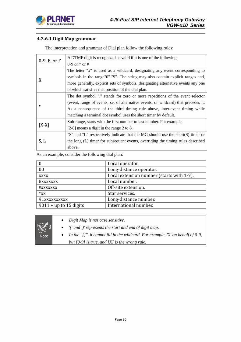
4.2.6.1 Digit Map grammar
The interpretation and grammar of Dial plan follow the following rules:
0-9, E, or F A DTMF digit is recognized as valid if it is one of the following:
0-9 or * or #
X
The letter "x" is used as a wildcard, designating any event corresponding to
symbols in the range"0"-"9". The string may also contain explicit ranges and,
more generally, explicit sets of symbols, designating alternative events any one
of which satisfies that position of the dial plan.
•
The dot symbol "." stands for zero or more repetitions of the event selector
(event, range of events, set of alternative events, or wildcard) that precedes it.
As a consequence of the third timing rule above, inter-event timing while
matching a terminal dot symbol uses the short timer by default.
[X-X] Sub-range, starts with the first number to last number. For example,
[2-8] means a digit in the range 2 to 8.
S, L
"S" and "L" respectively indicate that the MG should use the short(S) timer or
the long (L) timer for subsequent events, overriding the timing rules described
above.
As an example, consider the following dial plan:
0 Local operator. 00 Long-distance operator. xxxx Local extension number (starts with 1-7). 8xxxxxxx Local number. #xxxxxxx Off-site extension. *xx Star services. 91xxxxxxxxxx Long-distance number. 9011 + up to 15 digits International number.
Digit Map is not case sensitive.
'(' and ')' represents the start and end of digit map.
In the "[]", it cannot fill in the wildcard. For example, 'X' on behalf of 0-9,
but [0-9] is true, and [X] is the wrong rule.
4-/8-Port SIP Internet Telephony Gateway VGW-x10 Series
Page 31
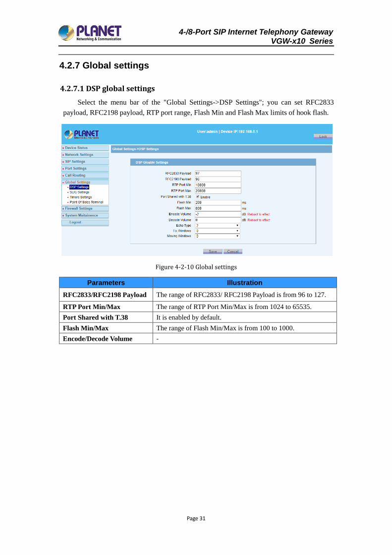
4.2.7 Global settings
4.2.7.1 DSP global settings
Select the menu bar of the "Global Settings->DSP Settings"; you can set RFC2833
payload, RFC2198 payload, RTP port range, Flash Min and Flash Max limits of hook flash.
Figure 4-2-10 Global settings
Parameters Illustration
RFC2833/RFC2198 Payload The range of RFC2833/ RFC2198 Payload is from 96 to 127.
RTP Port Min/Max The range of RTP Port Min/Max is from 1024 to 65535.
Port Shared with T.38 It is enabled by default.
Flash Min/Max The range of Flash Min/Max is from 100 to 1000.
Encode/Decode Volume -
4-/8-Port SIP Internet Telephony Gateway VGW-x10 Series
Page 32
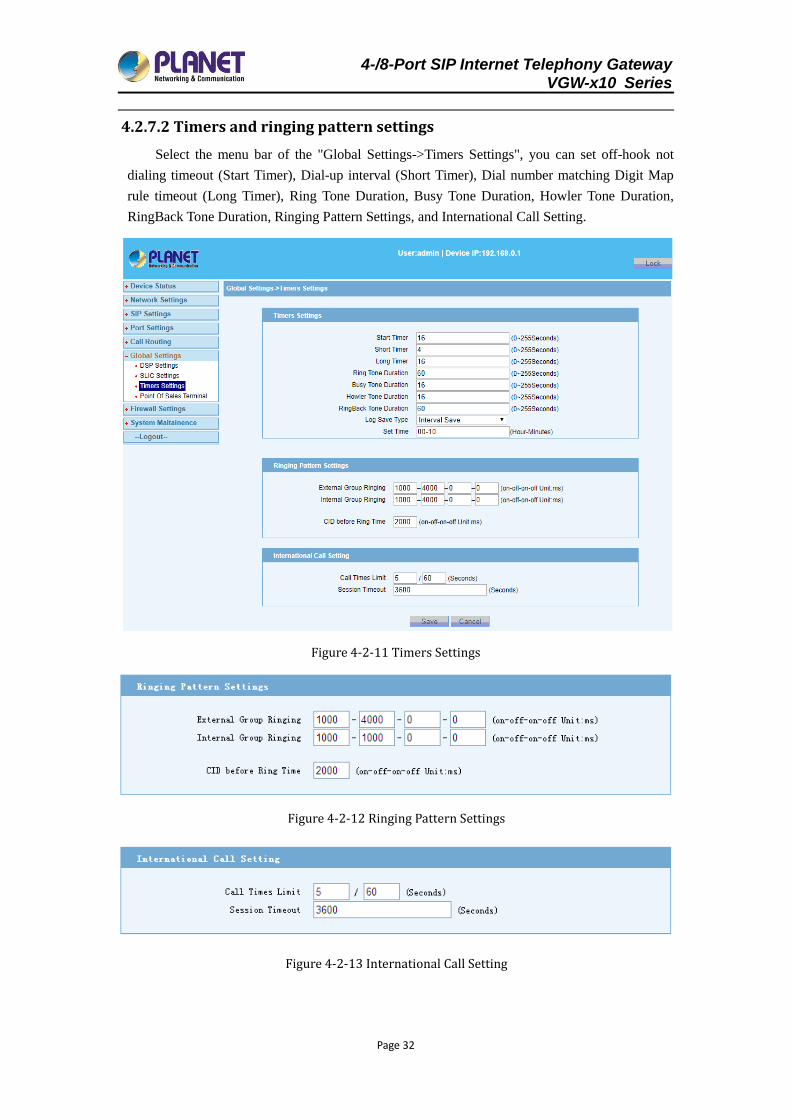
4.2.7.2 Timers and ringing pattern settings
Select the menu bar of the "Global Settings->Timers Settings", you can set off-hook not
dialing timeout (Start Timer), Dial-up interval (Short Timer), Dial number matching Digit Map
rule timeout (Long Timer), Ring Tone Duration, Busy Tone Duration, Howler Tone Duration,
RingBack Tone Duration, Ringing Pattern Settings, and International Call Setting.
Figure 4-2-11 Timers Settings
Figure 4-2-12 Ringing Pattern Settings
Figure 4-2-13 International Call Setting
4-/8-Port SIP Internet Telephony Gateway VGW-x10 Series
Page 33
Parameters Illustration
Start Timer Its default value is 16 sec
Short Timer Its default value is 4 sec
Long Timer Its default value is 16 sec
Ring Tone Duration Its default value is 60 sec
Busy Tone Duration Its default value is 16 sec
Howler Tone Duration Its default value is 16 sec
RingBack Tone Duration Its default value is 40 sec
Ringing Pattern Settings
The ringing sequence (interval): External Group Ringing and
Internal Group Ringing; External Group Ringing function is
used by default.
International Call Setting International outgoing call restrictions.
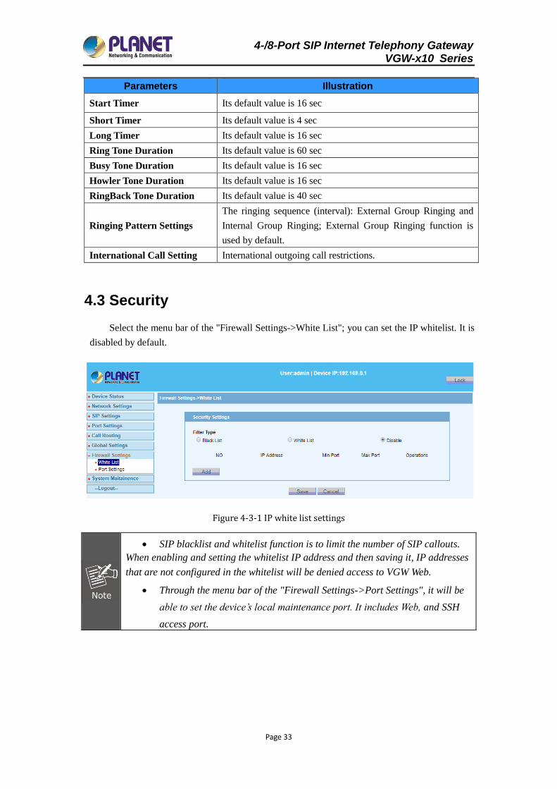
4.3 Security
Select the menu bar of the "Firewall Settings->White List"; you can set the IP whitelist. It is
disabled by default.
Figure 4-3-1 IP white list settings
SIP blacklist and whitelist function is to limit the number of SIP callouts.
When enabling and setting the whitelist IP address and then saving it, IP addresses
that are not configured in the whitelist will be denied access to VGW Web.
Through the menu bar of the "Firewall Settings->Port Settings", it will be
able to set the device’s local maintenance port. It includes Web, and SSH
access port.
4-/8-Port SIP Internet Telephony Gateway VGW-x10 Series
Page 34
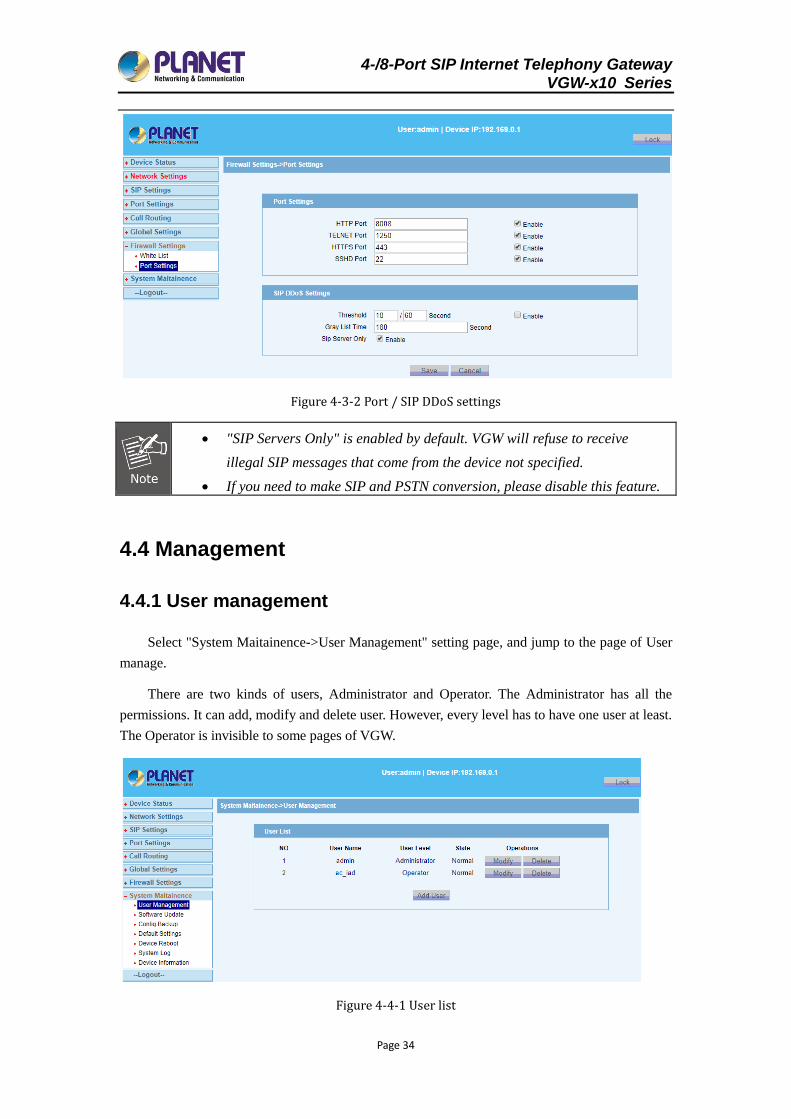
Figure 4-3-2 Port / SIP DDoS settings
"SIP Servers Only" is enabled by default. VGW will refuse to receive
illegal SIP messages that come from the device not specified.
If you need to make SIP and PSTN conversion, please disable this feature.
4.4 Management
4.4.1 User management
Select "System Maitainence->User Management" setting page, and jump to the page of User
manage.
There are two kinds of users, Administrator and Operator. The Administrator has all the
permissions. It can add, modify and delete user. However, every level has to have one user at least.
The Operator is invisible to some pages of VGW.
Figure 4-4-1 User list
4-/8-Port SIP Internet Telephony Gateway VGW-x10 Series
Page 35
If you enter the password wrong for more than five times, your current account will
be locked, and you will not be able to log in VGW anymore. If you happen to
remember the password, you need to log in device with the correct password and
unlock it through serial port (i.e. CONSOLE port). Otherwise, please contact the
manufacturer.
Unlock command as follows:
#system>user unlock username
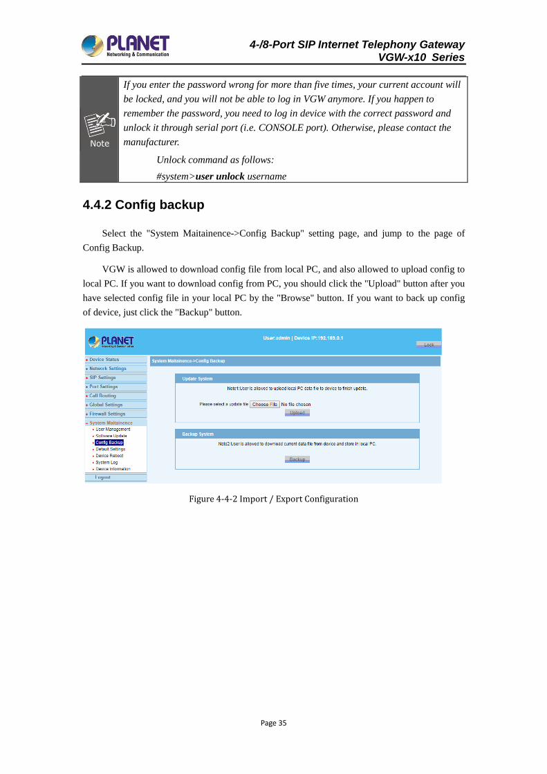
4.4.2 Config backup
Select the "System Maitainence->Config Backup" setting page, and jump to the page of
Config Backup.
VGW is allowed to download config file from local PC, and also allowed to upload config to
local PC. If you want to download config from PC, you should click the "Upload" button after you
have selected config file in your local PC by the "Browse" button. If you want to back up config
of device, just click the "Backup" button.
Figure 4-4-2 Import / Export Configuration
4-/8-Port SIP Internet Telephony Gateway VGW-x10 Series
Page 36
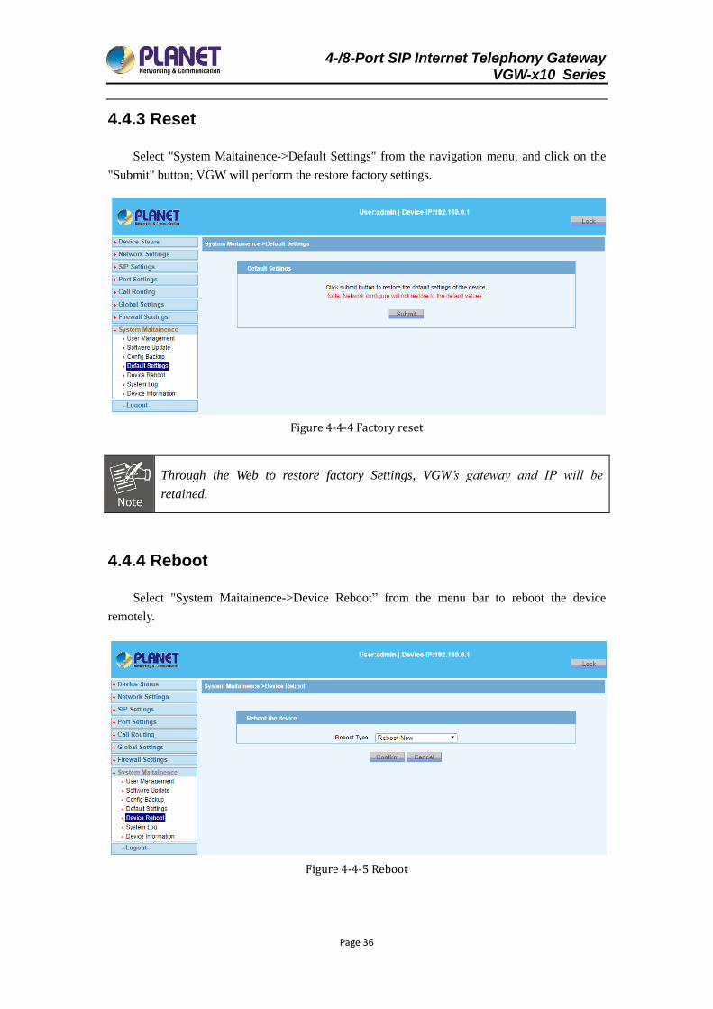
4.4.3 Reset
Select "System Maitainence->Default Settings" from the navigation menu, and click on the
"Submit" button; VGW will perform the restore factory settings.
Figure 4-4-4 Factory reset
Through the Web to restore factory Settings, VGW’s gateway and IP will be
retained.
4.4.4 Reboot
Select "System Maitainence->Device Reboot” from the menu bar to reboot the device
remotely.
Figure 4-4-5 Reboot
4-/8-Port SIP Internet Telephony Gateway VGW-x10 Series
Page 37
Through the Web to reboot device, unsaved data will be lost. It will take about 1
minute to restart.
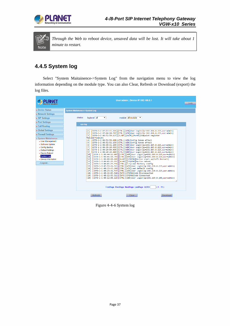
4.4.5 System log
Select "System Maitainence->System Log" from the navigation menu to view the log
information depending on the module type. You can also Clear, Refresh or Download (export) the
log files.
Figure 4-4-6 System log
4-/8-Port SIP Internet Telephony Gateway VGW-x10 Series
Page 38
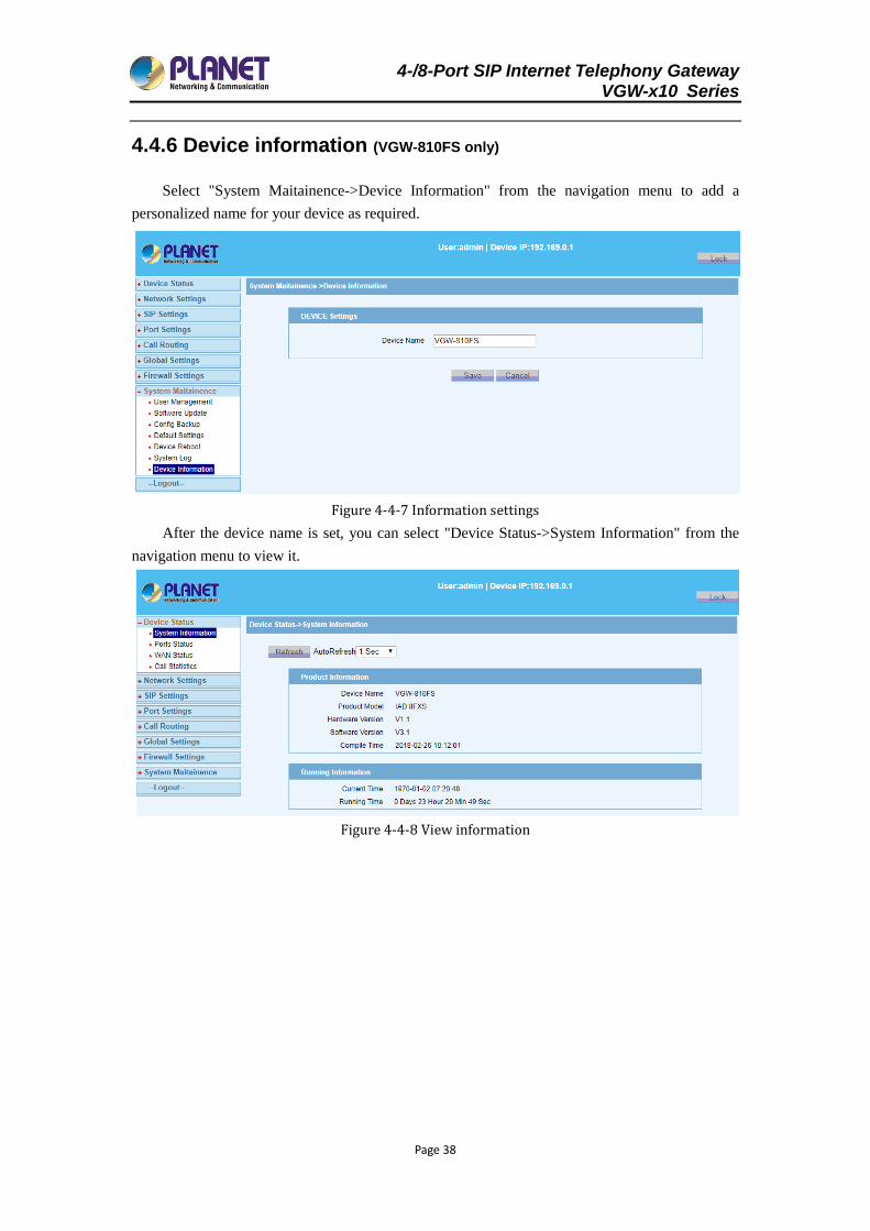
4.4.6 Device information (VGW-810FS only)
Select "System Maitainence->Device Information" from the navigation menu to add a
personalized name for your device as required.
Figure 4-4-7 Information settings
After the device name is set, you can select "Device Status->System Information" from the
navigation menu to view it.
Figure 4-4-8 View information
4-/8-Port SIP Internet Telephony Gateway VGW-x10 Series
Page 39
Chapter 5 Examples
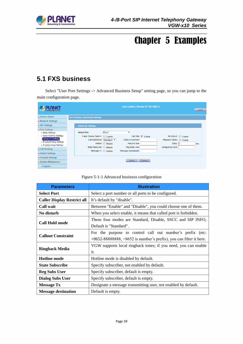
5.1 FXS business
Select "User Port Settings -> Advanced Business Setup" setting page, so you can jump to the
main configuration page.
Figure 5-1-1 Advanced business configuration
Parameters Illustration
Select Port Select a port number or all ports to be configured.
Caller Display Restrict all It’s default by "disable".
Call wait Between "Enable" and "Disable", you could choose one of them.
No disturb When you select enable, it means that called port is forbidden.
Call Hold mode These four modes are Standard, Disable, SSCC and SIP INFO,
Default is "Standard".
Callout Constraint For the purpose to control call out number’s prefix (etc:
+8652-88888888, +8652 is number’s prefix), you can filter it here.
Ringback Media VGW supports local ringback tones; if you need, you can enable
it.
Hotline mode Hotline mode is disabled by default.
State Subscribe Specify subscriber, not enabled by default.
Reg Subs User Specify subscriber, default is empty.
Dialog Subs User Specify subscriber, default is empty.
Message Tx Designate a message transmitting user, not enabled by default.
Message destination Default is empty.
4-/8-Port SIP Internet Telephony Gateway VGW-x10 Series
Page 40
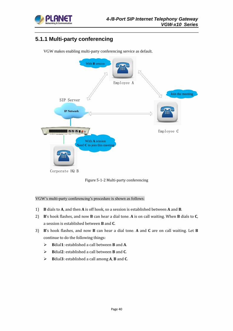
5.1.1 Multi-party conferencing
VGW makes enabling multi-party conferencing service as default.
Employee A
Corporate HQ B
Employee C
With A session
Need C to join this meeting
Join the meeting
IP Network
With B seeion
SIP Server
Figure 5-1-2 Multi-party conferencing
VGW’s multi-party conferencing’s procedure is shown as follows:
1) B dials to A, and then A is off hook, so a session is established between A and B.
2) B’s hook flashes, and now B can hear a dial tone. A is on call waiting. When B dials to C,
a session is established between B and C.
3) B’s hook flashes, and now B can hear a dial tone. A and C are on call waiting. Let B
continue to do the following things:
Bdial1: established a call between B and A.
Bdial2: established a call between B and C.
Bdial3: established a call among A, B and C.
With B session
4-/8-Port SIP Internet Telephony Gateway VGW-x10 Series
Page 41
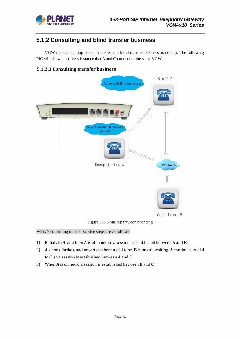
5.1.2 Consulting and blind transfer business
VGW makes enabling consult transfer and blind transfer business as default. The following
PIC will show a business instance that A and C connect to the same VGW.
5.1.2.1 Consulting transfer business
Consultant B
Staff C
Asked whether B can take
the call
Agree with B phone access
IP NetworkReceptionist A
Figure 5-1-3 Multi-party conferencing
VGW’s consulting transfer service steps are as follows:
1) B dials to A, and then A is off hook, so a session is established between A and B.
2) A’s hook flashes, and now A can hear a dial tone, B is on call waiting. A continues to dial
to C, so a session is established between A and C.
3) When A is on hook, a session is established between B and C.
4-/8-Port SIP Internet Telephony Gateway VGW-x10 Series
Page 42
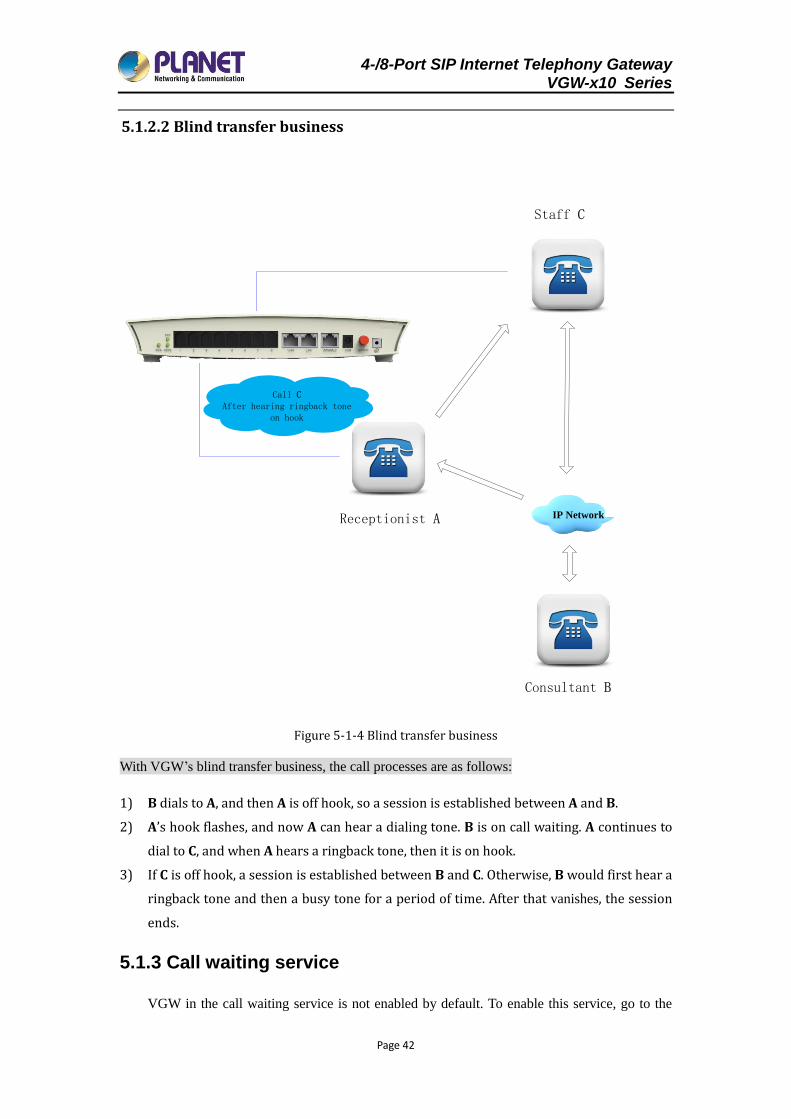
5.1.2.2 Blind transfer business
Staff C
Consultant B
IP NetworkReceptionist A
Call CAfter hearing ringback tone
on hook
Figure 5-1-4 Blind transfer business
With VGW’s blind transfer business, the call processes are as follows:
1) B dials to A, and then A is off hook, so a session is established between A and B.
2) A’s hook flashes, and now A can hear a dialing tone. B is on call waiting. A continues to
dial to C, and when A hears a ringback tone, then it is on hook.
3) If C is off hook, a session is established between B and C. Otherwise, B would first hear a
ringback tone and then a busy tone for a period of time. After that vanishes, the session
ends.
5.1.3 Call waiting service
VGW in the call waiting service is not enabled by default. To enable this service, go to the
4-/8-Port SIP Internet Telephony Gateway VGW-x10 Series
Page 43
"Port Settings->Advanced Settings" configuration page to enable the corresponding port "Call
Wait" function.
The call waiting service steps are as follows (refer to "Figure 5-1: Multi-party conferencing"
steps; for example, B is on call waiting service):
1) A dials to B, and then B is off hook, so a session is established between A and B.
2) C dials to B, during the call, B will hear the call waiting tone.
3) B’s hook flashes, and now B hears the dialing tone at which time both A and C are
waiting call.
B continues to do the following:
B dial 0: stop C.
B dial 2: connect with C.
For the port that is on call waiting service. When user’s hook flashes, press number
"2", and a session is established between one user and one user. When number "2"
is pressed twice, a session is established between another user and another. Press
number "0" to stop another user, meaning to keep the current session.
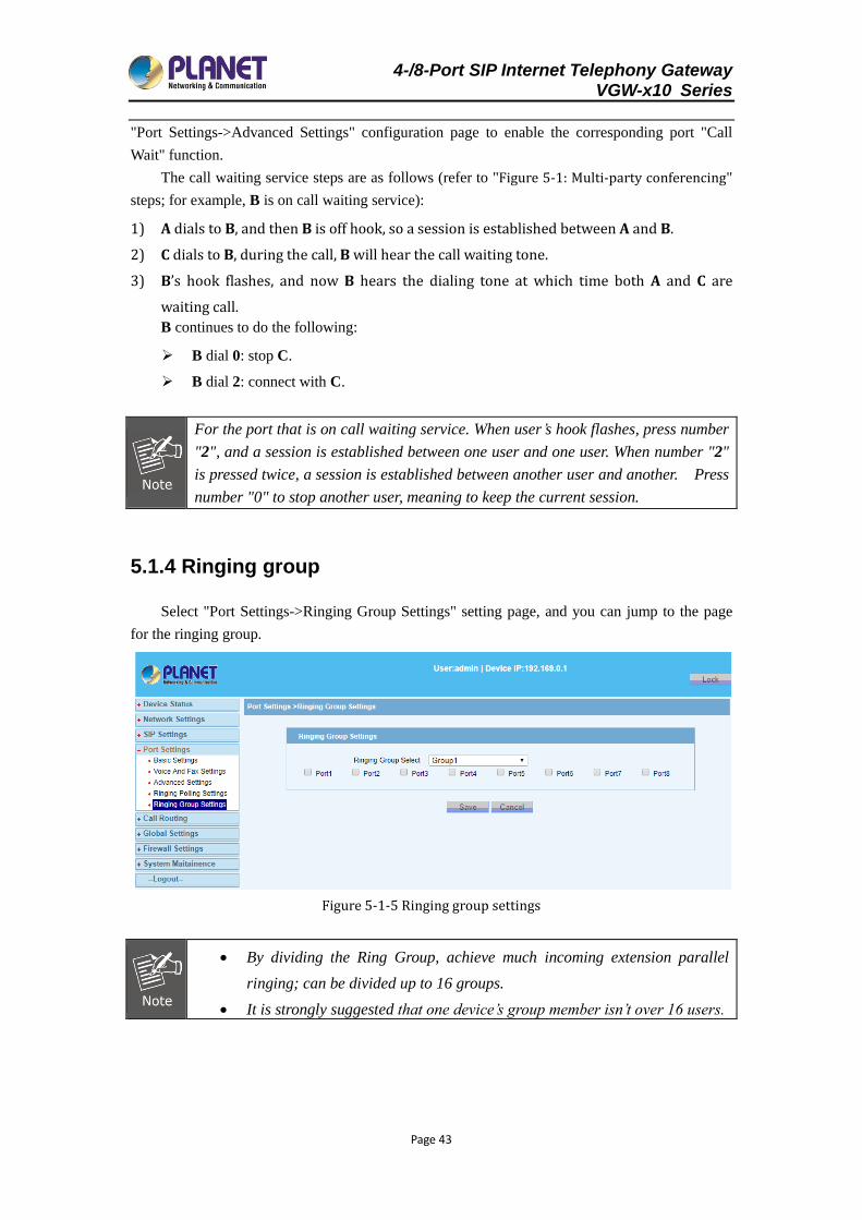
5.1.4 Ringing group
Select "Port Settings->Ringing Group Settings" setting page, and you can jump to the page
for the ringing group.
Figure 5-1-5 Ringing group settings
By dividing the Ring Group, achieve much incoming extension parallel
ringing; can be divided up to 16 groups.
It is strongly suggested that one device’s group member isn’t over 16 users.
4-/8-Port SIP Internet Telephony Gateway VGW-x10 Series
Page 44
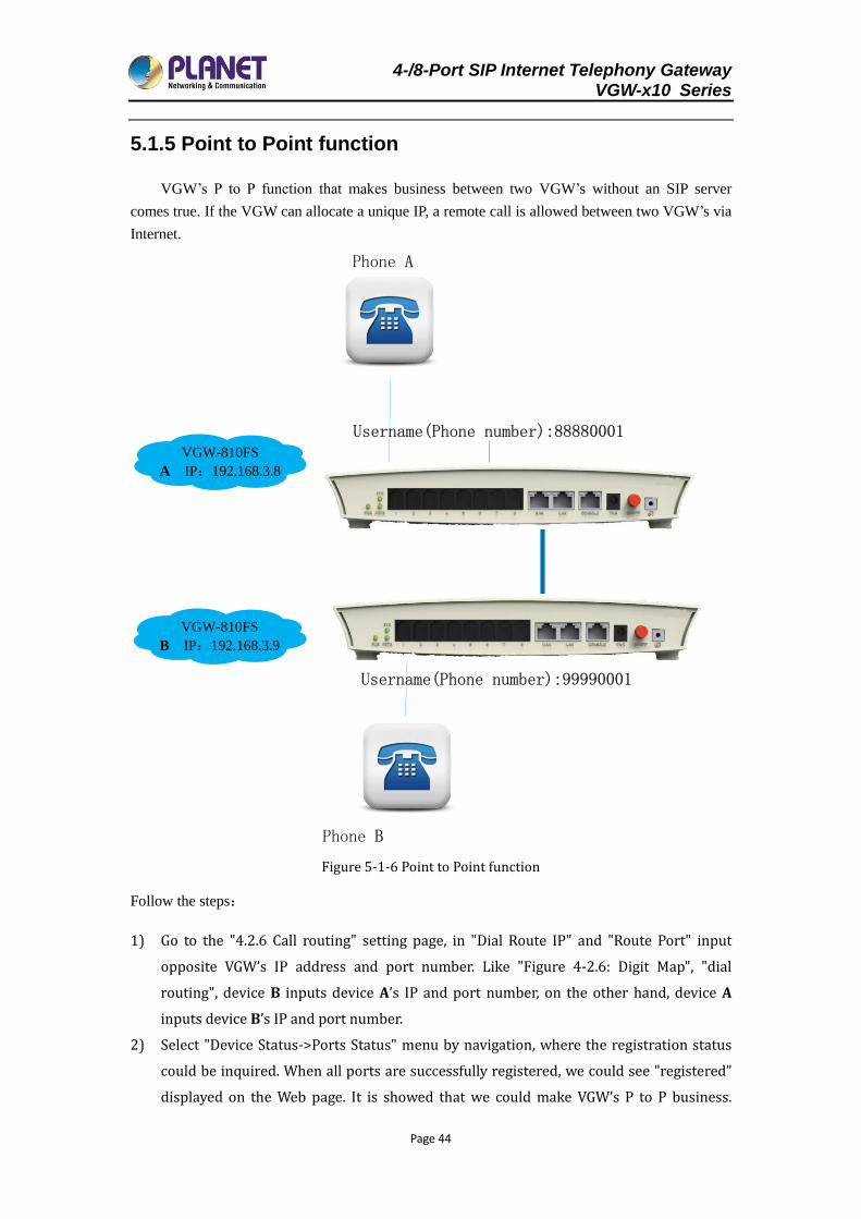
5.1.5 Point to Point function
VGW’s P to P function that makes business between two VGW’s without an SIP server
comes true. If the VGW can allocate a unique IP, a remote call is allowed between two VGW’s via
Internet.
VGW-810FS
A IP:192.168.3.8
Username(Phone number):88880001
Phone A
VGW-810FS
B IP:192.168.3.9
Phone B
Username(Phone number):99990001
Figure 5-1-6 Point to Point function
Follow the steps:
1) Go to the "4.2.6 Call routing" setting page, in "Dial Route IP" and "Route Port" input
opposite VGW’s IP address and port number. Like "Figure 4-2.6: Digit Map", "dial
routing", device B inputs device A’s IP and port number, on the other hand, device A
inputs device B’s IP and port number.
2) Select "Device Status->Ports Status" menu by navigation, where the registration status
could be inquired. When all ports are successfully registered, we could see "registered”
displayed on the Web page. It is showed that we could make VGW’s P to P business.
4-/8-Port SIP Internet Telephony Gateway VGW-x10 Series
Page 45
Otherwise, please check WAN port’s configuration parameters and network.
5.2 System update
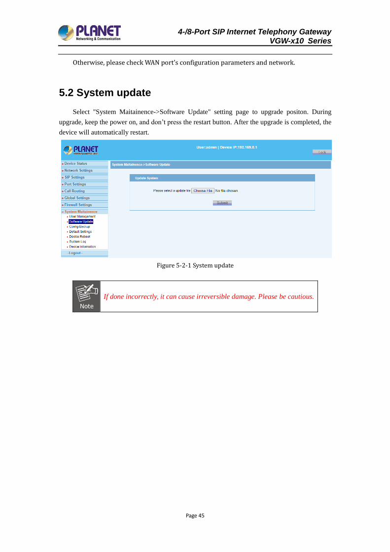
Select "System Maitainence->Software Update" setting page to upgrade positon. During
upgrade, keep the power on, and don’t press the restart button. After the upgrade is completed, the
device will automatically restart.
Figure 5-2-1 System update
If done incorrectly, it can cause irreversible damage. Please be cautious.
4-/8-Port SIP Internet Telephony Gateway VGW-x10 Series
Page 46
Chapter 6 FAQs
6.1 CLI maintenance tools
CLI is a command-line terminal maintenance tool. In order to solve problems efficiently, you
should have a certain understanding about the following details.
The following procedure parameters are "factory default ". For more parameter information,
refer to "3.1.1 Factory parameters". When dealing with the issue, you should do according to the
actual configuration parameters.
6.1.1 Telnet login
We can make configuration on command-line terminal,manage device in-band.
When configurate VGW's technical parameter, we could use "telnet" to login.(First, ensure
that device's power is on, LAN port default IP is 192.169.0.1, subnet mask is 255.255.255.0)We
can make configuration from command terminal, manage device in-band.
VGW gateway allowed telnet to login WEB configuration by LAN or WAN port。However,
due to the WAN port IP address might be dynamically obtained through DHCP and PPPoE, which
is not easy for "telnet" to access, so it is strongly recommended that keep the LAN port to connect
"telnet". "telnet" login process can be performed as follows:
Prepare a direct or a cross network cable.
Keep network cable connect PC and VGW’s LAN port. If the LAN port LINK led is on, it
means that PC and device has been properly connected.
Modify/Add the PC IP address192.169.0.X (X is an integer greater than 2 and less than 254)
mask of 255.255.255.0.
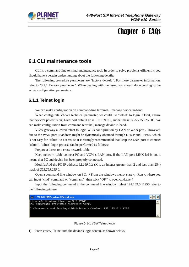
Open a command line window on PC。(From the windows menu<start>, <Run>, where you
can input "cmd" command or "command", then click "OK" to open cmd.exe.)
Input the following command in the command line window: telnet 192.169.0.11250 refer to
the following picture:
Figure 6-1-1 VGW Telnet login
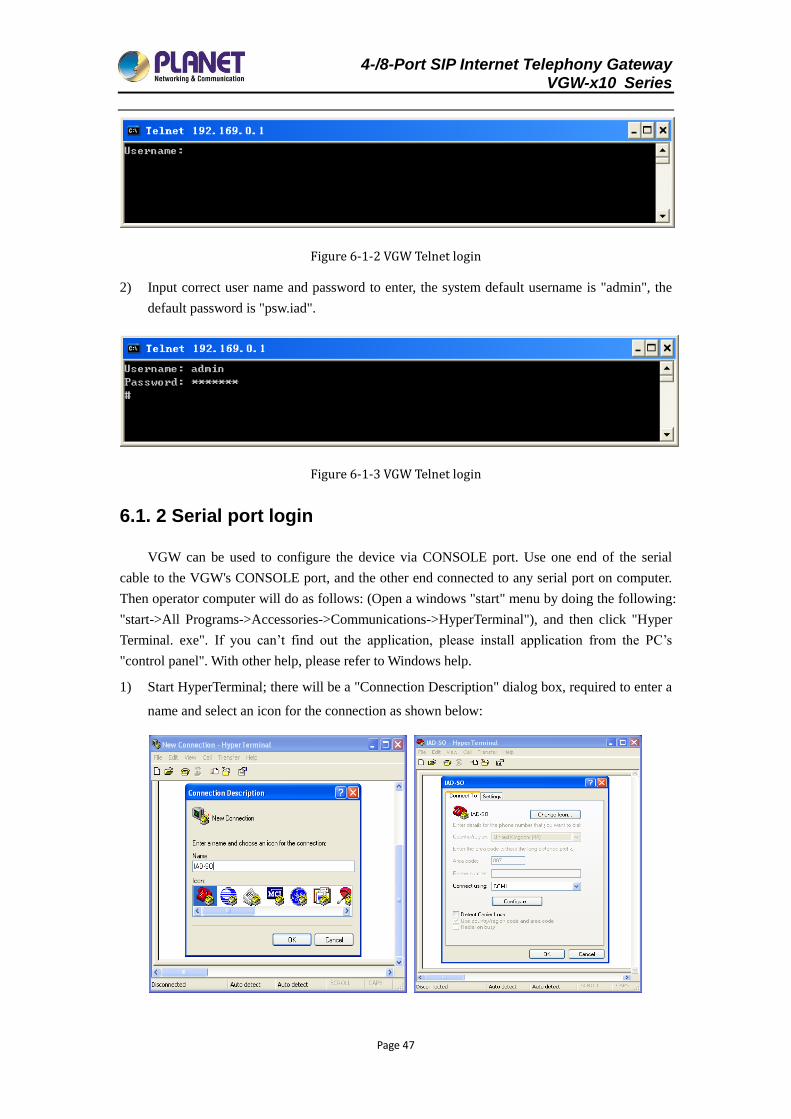
1) Press enter,Telnet into the device's login screen, as shown below:
4-/8-Port SIP Internet Telephony Gateway VGW-x10 Series
Page 47
Figure 6-1-2 VGW Telnet login
2) Input correct user name and password to enter, the system default username is "admin", the
default password is "psw.iad".
Figure 6-1-3 VGW Telnet login
6.1. 2 Serial port login
VGW can be used to configure the device via CONSOLE port. Use one end of the serial
cable to the VGW's CONSOLE port, and the other end connected to any serial port on computer.
Then operator computer will do as follows: (Open a windows "start" menu by doing the following:
"start->All Programs->Accessories->Communications->HyperTerminal"), and then click "Hyper
Terminal. exe". If you can’t find out the application, please install application from the PC’s
"control panel". With other help, please refer to Windows help.
1) Start HyperTerminal; there will be a "Connection Description" dialog box, required to enter a
name and select an icon for the connection as shown below:
4-/8-Port SIP Internet Telephony Gateway VGW-x10 Series
Page 48
Figure 6-1-4 HyperTerminal configuration
2) Input a connection name, and press the Enter key or use the mouse to click "OK" to enter the
next step. Then there will be a "connected" dialog. In the "Connect using" pull down menu,
your selected port must be in accordance with the port actually connected to the PC as shown
in picture below.
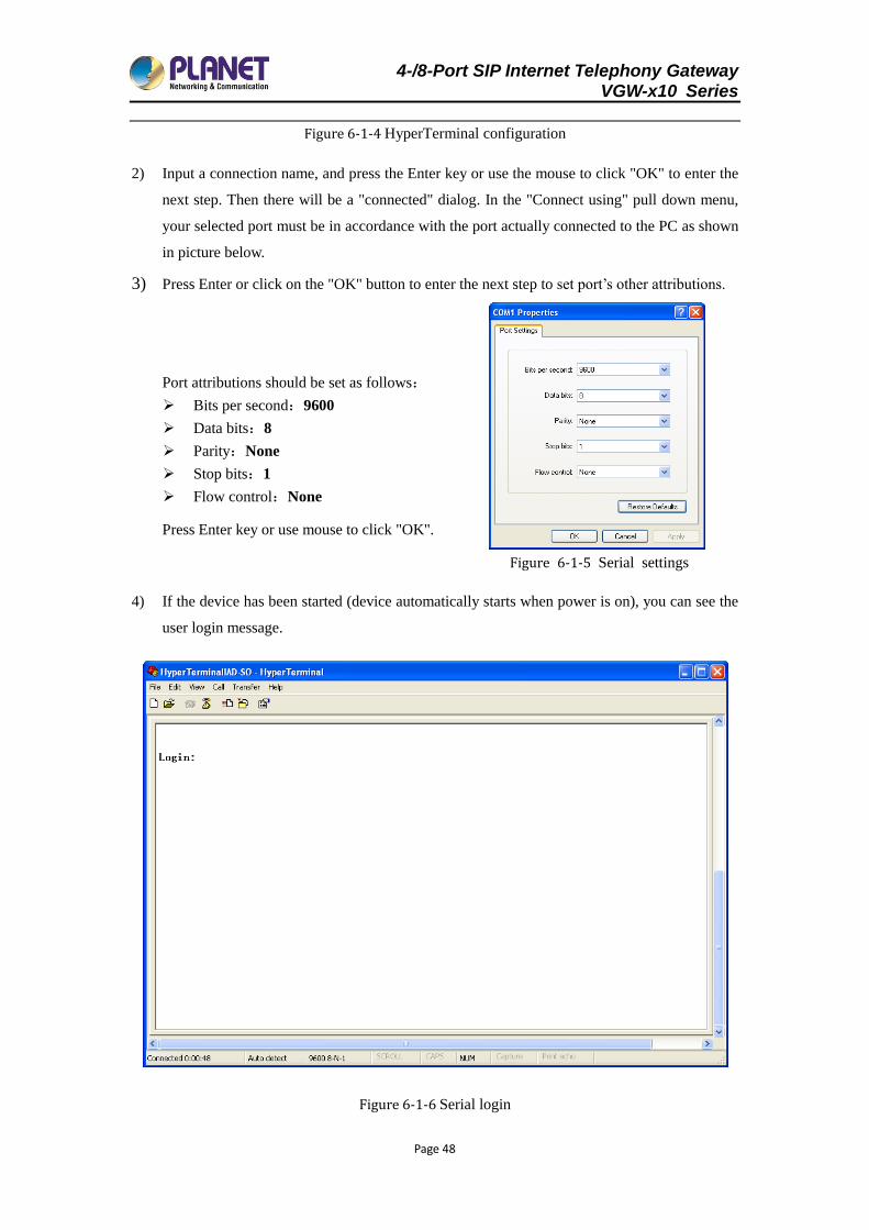
3) Press Enter or click on the "OK" button to enter the next step to set port’s other attributions.
Port attributions should be set as follows:
Bits per second:9600
Data bits:8
Parity:None
Stop bits:1
Flow control:None
Press Enter key or use mouse to click "OK".
Figure 6-1-5 Serial settings
4) If the device has been started (device automatically starts when power is on), you can see the
user login message.
Figure 6-1-6 Serial login
4-/8-Port SIP Internet Telephony Gateway VGW-x10 Series
Page 49
5) According to information on command screen, input correct login user name and password,
then you can log in.
If this is your first time to log in, please use the default account. System default username is
"admin", default password is "psw.iad". For details on the command, please refer to the
instructions on the back.
VGW CLI command maintenance tools, in addition to supporting Serial, also
support SHH. As SHH function usage is similar to Serial, do not repeat here.
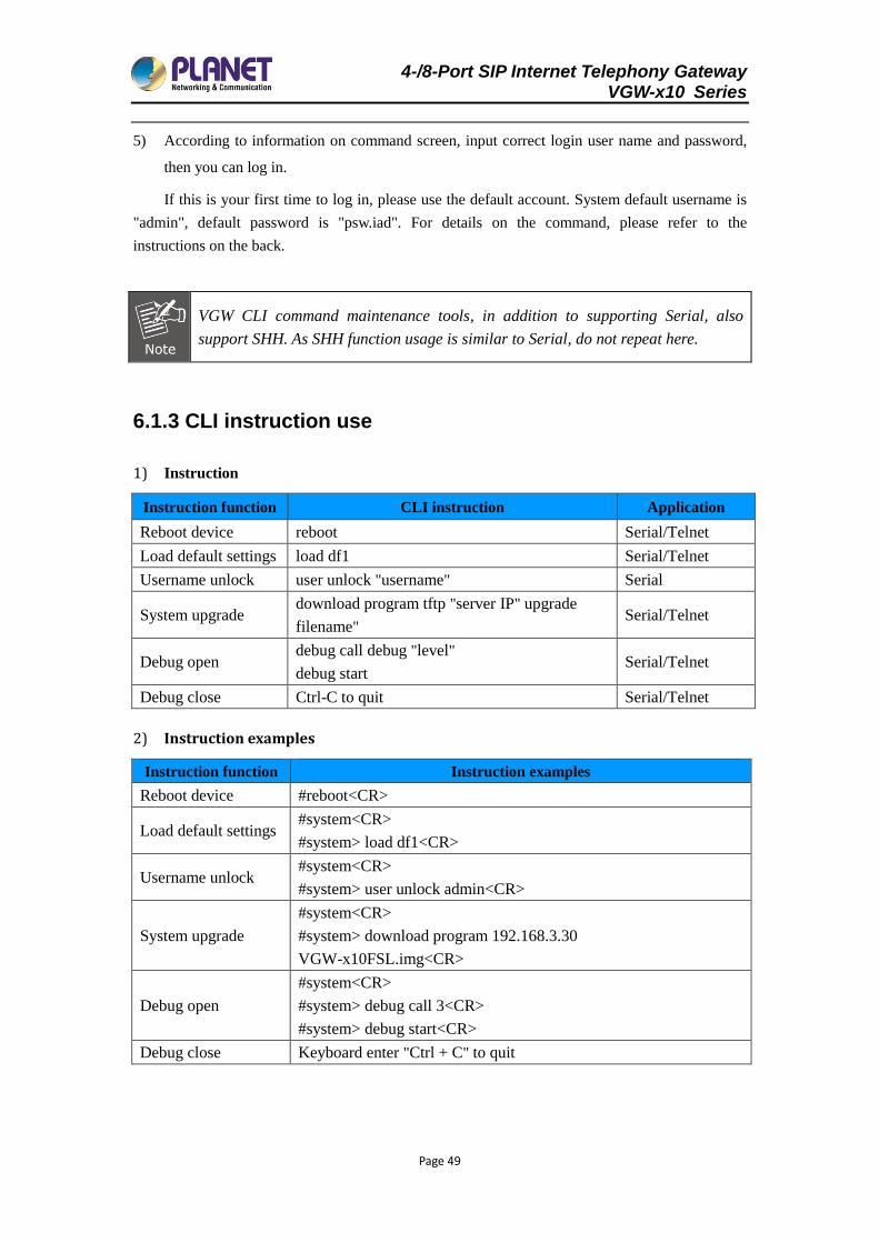
6.1.3 CLI instruction use
1) Instruction
Instruction function CLI instruction Application
Reboot device reboot Serial/Telnet
Load default settings load df1 Serial/Telnet
Username unlock user unlock "username" Serial
System upgrade download program tftp "server IP" upgrade
filename" Serial/Telnet
Debug open debug call debug "level"
debug start Serial/Telnet
Debug close Ctrl-C to quit Serial/Telnet
2) Instruction examples
Instruction function Instruction examples
Reboot device #reboot<CR>
Load default settings #system<CR>
#system> load df1<CR>
Username unlock #system<CR>
#system> user unlock admin<CR>
System upgrade
#system<CR>
#system> download program 192.168.3.30
VGW-x10FSL.img<CR>
Debug open
#system<CR>
#system> debug call 3<CR>
#system> debug start<CR>
Debug close Keyboard enter "Ctrl + C" to quit
4-/8-Port SIP Internet Telephony Gateway VGW-x10 Series
Page 50
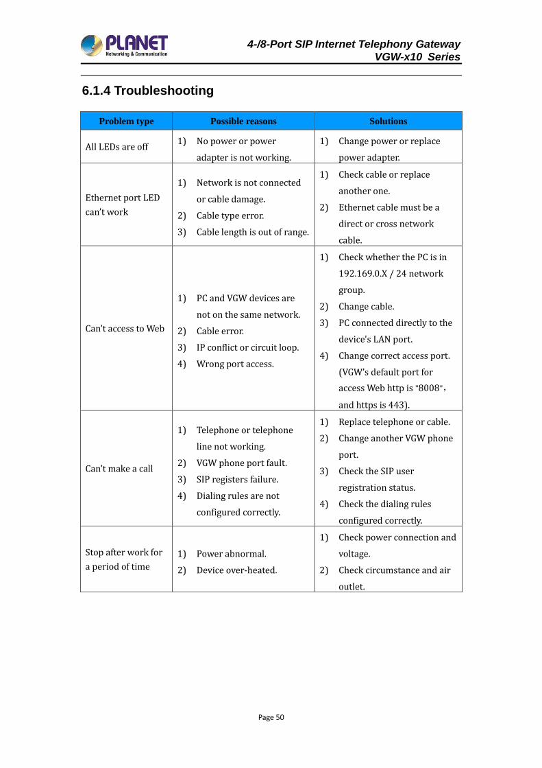
6.1.4 Troubleshooting
Problem type Possible reasons Solutions
All LEDs are off 1) No power or power
adapter is not working.
1) Change power or replace
power adapter.
Ethernet port LED
can’t work
1) Network is not connected
or cable damage.
2) Cable type error.
3) Cable length is out of range.
1) Check cable or replace
another one.
2) Ethernet cable must be a
direct or cross network
cable.
Can’t access to Web
1) PC and VGW devices are
not on the same network.
2) Cable error.
3) IP conflict or circuit loop.
4) Wrong port access.
1) Check whether the PC is in
192.169.0.X / 24 network
group.
2) Change cable.
3) PC connected directly to the
device's LAN port.
4) Change correct access port.
(VGW’s default port for
access Web http is "8008",
and https is 443).
Can’t make a call
1) Telephone or telephone
line not working.
2) VGW phone port fault.
3) SIP registers failure.
4) Dialing rules are not
configured correctly.
1) Replace telephone or cable.
2) Change another VGW phone
port.
3) Check the SIP user
registration status.
4) Check the dialing rules
configured correctly.
Stop after work for
a period of time
1) Power abnormal.
2) Device over-heated.
1) Check power connection and
voltage.
2) Check circumstance and air
outlet.