4 armature windings - nptelnptel.ac.in/courses/iit-madras/electrical_machines_i/...electrical...
TRANSCRIPT
Electrical Machines I Prof. Krishna Vasudevan, Prof. G. Sridhara Rao, Prof. P. Sasidhara Rao
Indian Institute of Technology Madras
4 Armature Windings
X
X
X
xx
x
x
x
xx
x
x
x
X
x
x
x
x
x
x
x
x
N
N
SS
v
X
X
XX
Main field
Compole field
Compensating
winding
Commutator
& Brush
Shaft
Armature
winding
Yoke
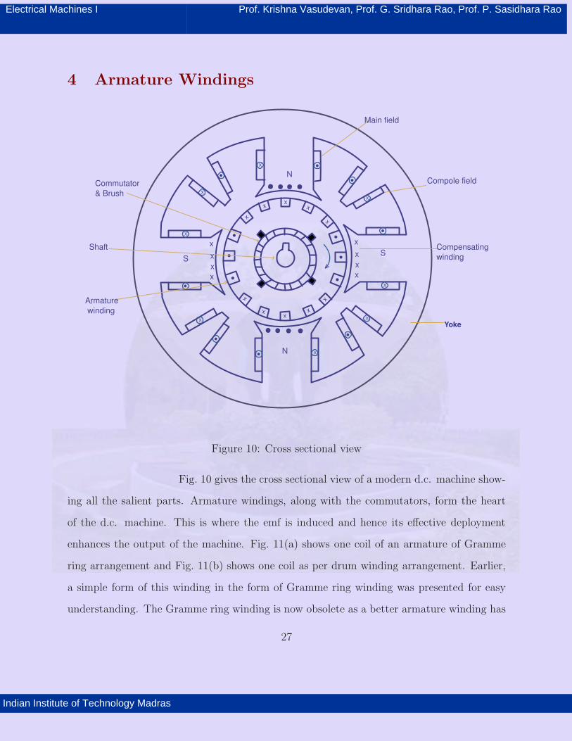
Figure 10: Cross sectional view
Fig. 10 gives the cross sectional view of a modern d.c. machine show-
ing all the salient parts. Armature windings, along with the commutators, form the heart
of the d.c. machine. This is where the emf is induced and hence its effective deployment
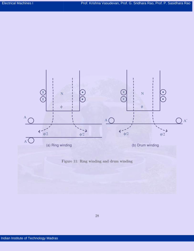
enhances the output of the machine. Fig. 11(a) shows one coil of an armature of Gramme
ring arrangement and Fig. 11(b) shows one coil as per drum winding arrangement. Earlier,
a simple form of this winding in the form of Gramme ring winding was presented for easy
understanding. The Gramme ring winding is now obsolete as a better armature winding has
27
Electrical Machines I Prof. Krishna Vasudevan, Prof. G. Sridhara Rao, Prof. P. Sasidhara Rao
Indian Institute of Technology Madras
X
X
φ/2 φ/2
φ
Ν X
X
φ/2 φ/2
φ
Ν
ΑΑ’Α
Α’(a) Ring winding (b) Drum winding
Figure 11: Ring winding and drum winding
28
Electrical Machines I Prof. Krishna Vasudevan, Prof. G. Sridhara Rao, Prof. P. Sasidhara Rao
Indian Institute of Technology Madras
been invented in the form of a drum winding. The ring winding has only one conductor in
a turn working as an active conductor. The second conductor is used simply to complete
the electrical connections. Thus the effectiveness of the electric circuit is only 50 percent.
Looking at it differently, half of the magnetic flux per pole links with each coil. Also, the
return conductor has to be wound inside the bore of the rotor, and hence the rotor diameter
is larger and mounting of the rotor on the shaft is made difficult.
In a drum winding both forward and return conductors are housed in slots cut
on the armature (or drum). Both the conductors have emf induced in them. Looking at it
differently the total flux of a pole is linked with a turn inducing much larger voltage induced
in the same. The rotor is mechanically robust with more area being available for carrying
the flux. There is no necessity for a rotor bore. The rotor diameters are smaller. Mechanical
problems that existed in ring winding are no longer there with drum windings. The coils
could be made of single conductors (single turn coils) or more number of conductors in series
(multi turn coils). These coils are in turn connected to form a closed winding. The two sides
of the coil lie under two poles one north and the other south, so that the induced emf in
them are always additive by virtue of the end connection. Even though the total winding
is a closed one the sum of the emfs would be zero at all times. Thus there is no circulating
current when the armature is not loaded. The two sides of the coil, if left on the surface, will
fly away due to centrifugal forces. Hence slots are made on the surface and the conductors
are placed in these slots and fastened by steel wires to keep them in position. Each armature
slot is partitioned into two layers, a top layer and a bottom layer. The winding is called as
a double layer winding. This is a direct consequence of the symmetry consideration. The
distance, measured along the periphery of the armature from any point under a pole to a
similar point under the neighboring pole is termed as a pole pitch. The forward conductor
is housed in the top layer of a slot and the return conductor is housed in the bottom layer
29

Electrical Machines I Prof. Krishna Vasudevan, Prof. G. Sridhara Rao, Prof. P. Sasidhara Rao
Indian Institute of Technology Madras
Active
Lower coil sideUpper coil side
Inactive
B
S NA A’
Inactive
C D
A’
D
C
AB
S
Lower
coil side
Upper coil side
N
S
N
S
Armature
(a) End view
(b) Developed view
Figure 12: Arrangement of a single coil of a drum winding
30
Electrical Machines I Prof. Krishna Vasudevan, Prof. G. Sridhara Rao, Prof. P. Sasidhara Rao
Indian Institute of Technology Madras
of a slot which is displaced by about one pole pitch. The junction of two coils is terminated
on a commutator segment. Thus there are as many commutator segments as the number of
coils. In a double layer winding in S slots there are 2S layers. Two layers are occupied by a
coil and hence totally there are S coils. The S junctions of these S coils are terminated on S
commutator segments. The brushes are placed in such a manner that a maximum voltage
appears across them. While the number of parallel circuits in the case of ring winding is
equal to the number of poles, in the case of drum winding a wide variety of windings are
possible. The number of brushes and parallel paths thus vary considerably. The physical
arrangement of a single coil is shown in Fig. 12 to illustrate its location and connection to
the commutators.
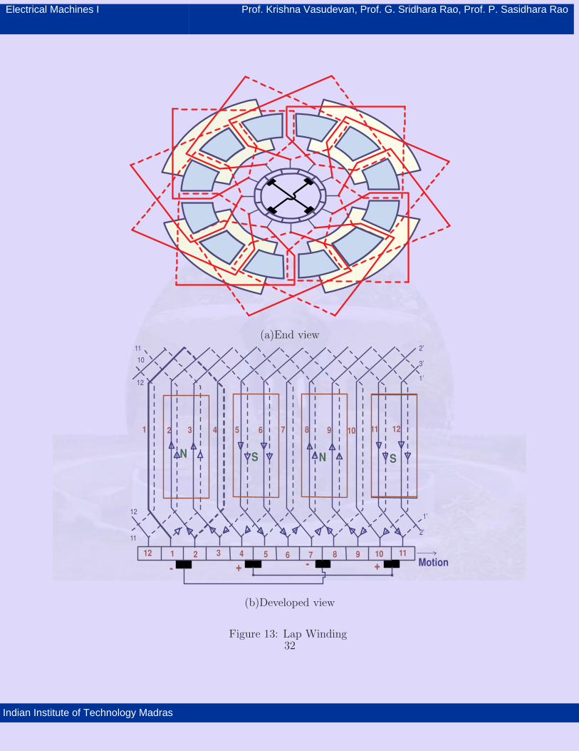
Fig. 13 shows the axial side view while Fig. 13-(b) shows the cut and spread view
of the machine. The number of turns in a coil can be one (single turn coils) or more (multi
turn coils ). As seen earlier the sum of the instantaneous emfs appears across the brushes.
This sum gets altered by the voltage of a coil that is being switched from one circuit to the
other or which is being commutated. As this coil in general lies in the magnetic neutral
axis it has a small value of voltage induced in it. This change in the sum expressed as the
fraction of the total induced voltage is called as the ripple. In order to reduce the ripple,
one can increase the number of coils coming in series between the brushes. As the number
of coils is the same as the number of slots in an armature with two coil sides per slot one is
forced to increase the number of slots. However increasing the slot number makes the tooth
width too narrow and makes them mechanically weak.
To solve this problem the slots are partitioned vertically to increase the number
of coil sides. This is shown in Fig. 14. In the figure, the conductors a, b and c belong to a
coil. Such 2/3 coils occupy the 2/3 top coil sides of the slot. In the present case the number
of coils in the armature is 2S/3S.
31
Electrical Machines I Prof. Krishna Vasudevan, Prof. G. Sridhara Rao, Prof. P. Sasidhara Rao
Indian Institute of Technology Madras
(a)End view
- +- +
1 2 3 4 5 6 7 8 9 10 11
1 2 3 4 5 6 7 8 9 10 11
12
12
SNSN
Motion
2’
1’
1’
3’
2’11
10
12
12
11
(b)Developed view
Figure 13: Lap Winding32

Electrical Machines I Prof. Krishna Vasudevan, Prof. G. Sridhara Rao, Prof. P. Sasidhara Rao
Indian Institute of Technology Madras
Press board
Press board
Copper
Mica Tape
(a) Single coil-side perlayer
(b) More coil sides perlayer
Figure 14: Partitioning of slots
33

Electrical Machines I Prof. Krishna Vasudevan, Prof. G. Sridhara Rao, Prof. P. Sasidhara Rao
Indian Institute of Technology Madras
As mentioned earlier, in a drum winding, the coils span a pole pitch where
ever possible. Such coils are called ’full pitched’ coils. The emf induced in the two active
conductors of such coils have identical emfs with opposite signs at all instants of time. If the
span is more than or less than the full pitch then the coil is said to be ’chorded’. In chorded
coils the induced emfs of the two conductor may be of the same sign and hence oppose each
other( for brief intervals of time). Slight short chording of the coil reduces overhang length
and saves copper and also improves commutation. Hence when the pole pitch becomes frac-
tional number, the smaller whole number may be selected discarding the fractional part.
Similar to the pitch of a coil one can define the winding pitch and commutator
pitch. In a d.c. winding the end of one coil is connected to the beginning of another coil
(not necessarily the next), this being symmetrically followed to include all the coils on the
armature. Winding pitch provides a means of indicating this. Similarly the commutator
pitch provides the information regarding the commutators to which the beginning and the
end of a coil are connected. Commutator pitch is the number of ’micas’ between the ends of
a coil. For all these information to be simple and useful the numbering scheme of the coils
and commutator segments becomes important. One simple method is to number only the
top coil side of the coils in sequence. The return conductor need not be numbered. As a
double layer is being used the bottom coil side is placed in a slot displaced by one coil span
from the top coil side. Some times the coils are numbered as 1 − 1′
, 2 − 2′
etc. indicating
the second sides by 1′
, 2′
etc. The numbering of commutators segments are done similarly.
The commutator segment connected to top coil side of coil 1 is numbered 1. This method
of numbering is simple and easy to follow. It should be noted that changing of the pitch
34
Electrical Machines I Prof. Krishna Vasudevan, Prof. G. Sridhara Rao, Prof. P. Sasidhara Rao
Indian Institute of Technology Madras
of a coil slightly changes the induced emf in the same. The pitch of the winding however
substantially alters the nature of the winding.
The armature windings are classified into two families based on this. They are
called lap winding and wave winding. They can be simply stated in terms of the commutator
pitch used for the winding.
4.1 Lap winding
The commutator pitch for the lap windings is given by
yc= ±m, m = 1, 2, 3... (20)
where yc
is the commutator pitch, m is the order of the winding.
For m = 1 we get a simple lap winding, m = 2 gives duplex lap winding etc. yc= m
gives a multiplex lap winding of order m. The sign refers to the direction of progression
of the winding. Positive sign is used for ‘progressive’ winding and the negative sign for the
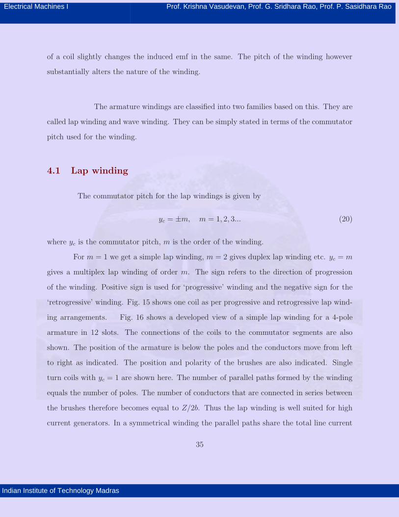
‘retrogressive’ winding. Fig. 15 shows one coil as per progressive and retrogressive lap wind-
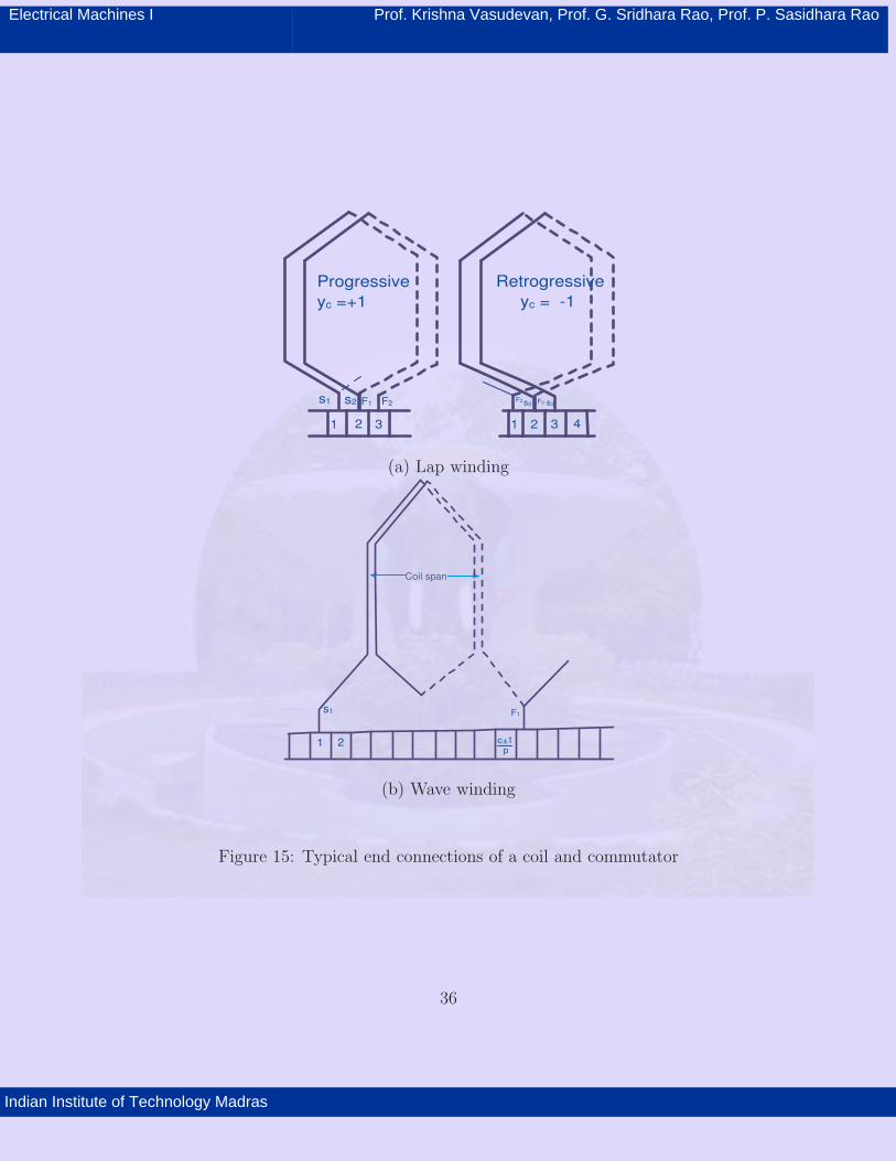
ing arrangements. Fig. 16 shows a developed view of a simple lap winding for a 4-pole
armature in 12 slots. The connections of the coils to the commutator segments are also
shown. The position of the armature is below the poles and the conductors move from left
to right as indicated. The position and polarity of the brushes are also indicated. Single
turn coils with yc= 1 are shown here. The number of parallel paths formed by the winding
equals the number of poles. The number of conductors that are connected in series between
the brushes therefore becomes equal to Z/2b. Thus the lap winding is well suited for high
current generators. In a symmetrical winding the parallel paths share the total line current
35
Electrical Machines I Prof. Krishna Vasudevan, Prof. G. Sridhara Rao, Prof. P. Sasidhara Rao
Indian Institute of Technology Madras
1 2 3
Progressive
yc =+1
s1 s2 F1 F2
1 2 3 4
Retrogressive
yc = -1
s3F3s2F2
(a) Lap winding
Coil span
1
s1 F1
2 c 1+_
p
(b) Wave winding
Figure 15: Typical end connections of a coil and commutator
36
Electrical Machines I Prof. Krishna Vasudevan, Prof. G. Sridhara Rao, Prof. P. Sasidhara Rao
Indian Institute of Technology Madras
1 2 3 4 5 6 7 8 9 10 11 1213 14
1 2
SN NS S
Motion
A1 A2B1 B2+ - + -
Figure 16: Developed view of a retrogressive Lap winding
37
Electrical Machines I Prof. Krishna Vasudevan, Prof. G. Sridhara Rao, Prof. P. Sasidhara Rao
Indian Institute of Technology Madras
equally.
The increase in the number of parallel paths in the armature winding brings
about a problem of circulating current. The induced emfs in the different paths tend to
differ slightly due to the non-uniformities in the magnetic circuit. This will be more with the
increase in the number of poles in the machine. If this is left uncorrected, circulating currents
appear in these closed parallel paths. This circulating current wastes power, produces heat
and over loads the brushes under loaded conditions. One method commonly adopted in d.c.
machines to reduce this problem is to provide equalizer connections. As the name suggests
these connections identify similar potential points of the different parallel paths and connect
them together to equalize the potentials. Any difference in the potential generates a local
circulating current and the voltages get equalized. Also, the circulating current does not
flow through the brushes loading them. The number of such equalizer connections, the
cross section for the conductor used for the equalizer etc are decided by the designer. An
example of equalizer connection is discussed now with the help of a 6-pole armature having
150 commutator segments. The coil numbers 1, 51 and 101 are identically placed under the
poles of same polarity as they are one pole-pair apart. There are 50 groups like that. In
order to limit the number of links to 5(say), the following connections are chosen. Then
1,11,21,31, and 41 are the coils under the first pair of poles. These are connected to their
counter parts displaced by 50 and 100 to yield 5 equalizer connections. There are 10 coils
connected in series between any two successive links. The wave windings shall be examined
next.
38

Electrical Machines I Prof. Krishna Vasudevan, Prof. G. Sridhara Rao, Prof. P. Sasidhara Rao
Indian Institute of Technology Madras
Motion-+
S N S N
+ A1 B1- A2 B2
17 18 1920 21 1 2 3 4 5 6 7 8 9 10 11 12 13 14 15 16
1
(a)Winding layout
Span : 1 to 6
Full pitch: 21/4=5.25 5~_
Yc=C 1+_
221 1+_
2= =
11
10}Commutator pitch 1-11 for retrogressive winding
1-11-21-10-20-9-19-8-18-7-17-
6-16-5-15-4-14-3-13-2-12-1
B2
A1A2
B1
v
v
(b)Parallel paths
Figure 17: Developed view of a Retrogressive Wave winding
39
Electrical Machines I Prof. Krishna Vasudevan, Prof. G. Sridhara Rao, Prof. P. Sasidhara Rao
Indian Institute of Technology Madras
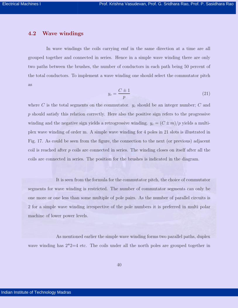
4.2 Wave windings
In wave windings the coils carrying emf in the same direction at a time are all
grouped together and connected in series. Hence in a simple wave winding there are only
two paths between the brushes, the number of conductors in each path being 50 percent of
the total conductors. To implement a wave winding one should select the commutator pitch
as
yc=
C ± 1
p(21)
where C is the total segments on the commutator. yc
should be an integer number; C and
p should satisfy this relation correctly. Here also the positive sign refers to the progressive
winding and the negative sign yields a retrogressive winding. yc= (C ±m)/p yields a multi-
plex wave winding of order m. A simple wave winding for 4 poles in 21 slots is illustrated in
Fig. 17. As could be seen from the figure, the connection to the next (or previous) adjacent
coil is reached after p coils are connected in series. The winding closes on itself after all the
coils are connected in series. The position for the brushes is indicated in the diagram.
It is seen from the formula for the commutator pitch, the choice of commutator
segments for wave winding is restricted. The number of commutator segments can only be
one more or one less than some multiple of pole pairs. As the number of parallel circuits is
2 for a simple wave winding irrespective of the pole numbers it is preferred in multi polar
machine of lower power levels.
As mentioned earlier the simple wave winding forms two parallel paths, duplex
wave winding has 2*2=4 etc. The coils under all the north poles are grouped together in
40
Electrical Machines I Prof. Krishna Vasudevan, Prof. G. Sridhara Rao, Prof. P. Sasidhara Rao
Indian Institute of Technology Madras
one circuit and the other circuit collects all the coils that are under all the south poles. Two
brush sets are therefore adequate. Occasionally people employ brush sets equal to the num-
ber of poles. This arrangement does not increase the number of parallel circuits but reduces
the current to be collected by each brush set. This can be illustrated by an example. A
4-pole wave connected winding with 21 commutator segments is taken. yc= (21−1)/2 = 10
. A retrogressive wave winding results. The total string of connection can be laid out as
shown below. If coil number 1 is assumed to be in the neutral axis then other neutral axis
coils are a pole pitch apart i.e. coils 6, 11, 16.
If the brushes are kept at commutator segment 1 and 6, nearly half the num-
ber of coils come under each circuit. The polarity of the brushes are positive and negative
alternately. Or, one could have two brushes at 11 and 16 or any two adjacent poles. By
having four brushes at 1, 6, 11 and 16 and connecting 1,11 and 6,16 still only two parallel
circuits are obtained. The brush currents however are halved. This method permits the use
of commutator of shorter length as lesser current is to be collected by each brush and thus
saving on the cost of the commutator. Fig. 17(b) illustrates this brush arrangement with
respect to a 21 slot 4 pole machine. Similarly proceeding, in a 6-pole winding 2,4 or 6 brush
sets may be used.
Multiplex windings of order m have m times the circuits compared to a simplex
winding and so also more restriction on the choice of the slots, coil sides, commutator
and brushes. Hence windings beyond duplex are very uncommon even though theoretically
possible. The duplex windings are used under very special circumstances when the number
of parallel paths had to be doubled.
41

Electrical Machines I Prof. Krishna Vasudevan, Prof. G. Sridhara Rao, Prof. P. Sasidhara Rao
Indian Institute of Technology Madras
4.3 Dummy coils and dummy commutator segments
Due to the restrictions posed by lap and wave windings on the choice of number
of slots and commutator segments a practical difficulty arises. Each machine with a certain
pole number, voltage and power ratings may require a particular number of slots and com-
mutator segments for a proper design. Thus each machine may be tailor made for a given
specification. This will require stocking and handling many sizes of armature and commu-
tator.
Sometimes due to the non-availability of a suitable slot number or commu-
tator, one is forced to design the winding in an armature readily available in stock. Such
designs, obviously, violate the symmetry conditions as armature slots and commutator seg-
ment may not match. If one is satisfied with approximate solutions then the designer can
omit the surplus coil or surplus commutator segment and complete the design. This is called
the use of a ’dummy’. All the coils are placed in the armature slots. The surplus coil is
electrically isolated and taped. It serves to provide mechanical balance against centrifugal
forces. Similarly, in the case of surplus commutator segment two adjacent commutator seg-
ments are connected together and treated as a single segment. These are called dummy coils
and dummy commutator segments. As mentioned earlier this approach must be avoided as
far as possible by going in for proper slot numbers and commutator. Slightly un-symmetric
winding may be tolerable in machines of smaller rating with very few poles.
42