4 b zfm br ak e for o ffshor e and m arine ap p lication ... · pdf filesafety in motion...
TRANSCRIPT

safety in motion Stromag Dessau
ENGINEERING THAT MOVES THE WORLD
PRODUCT CATALOGUE
4 BZFM Brake for Offshore and Marine Application, flood- and seawater-proof
4 BZFMElectromagnetic Spring-Applied Brake
Applications
X Holding and working brake variations for off shore and industrial applications where high protectionagainst harsh environment is essential
X Usable for windlasses, anchor winches, shipboard cranes, cargo winches, trawler winches
Main Features
Coil body with coil : Thermal class 155, nitrocarburated and postoxidated
Armature disc : Special protection: nitrocarburated and postoxidated
Brake disc : Special protection: nitrocarburated and postoxidated
Friction lining : Low wear rate with low torque fade over a high range of temperature.High thermal capacity.
Flange : To IEC standard
Cover : Manufactured of gray cast, from size 400 of seawater protected aluminium
Pinion : Nitrocarburated and postoxidated
Fixing screws : All stainless steel
Flying leads : 1,5 metre long, radial or axial
Seals : For high protection
Optional Extras
X Micro switch for monitoring switching states or wear detection
X Terminal box
X Standstill heater
X Preparation for speedometer installation
Switching modules
X Half wave or full wave
X Quick switching units
X Built in terminal box
X Attached for mounting into the motor terminal box
GKN Stromag Dessau GmbHDessauer Straße 1006844 Dessau-Roßlauwww.stromag.com
1 449-00004Version: B10.04.2014
4 BZFMElectromagnetic Spring-Applied Brake
Advantages
X Comprehensive torque range 63 – 11.000 Nm
X Operative without cover
X Type approvals: GL, LRS, ABS, DNV, BV, RR (on request)
X Simple assembly to motor, no dismantling of brake required
X Less wear
X Compatibility of consumable spares
X Simple maintenance, one time wear re-adjustment by reversing of the brake disc
X Proven reliable design
X Sealed inspection holes for air gap or lining wear
X Extremely low inertia
X High heat dissipation
X Free from axial loads when braking and running
X Suitable for vertical mounting, please consult GKN Stromag Dessau GmbH
X Many optional extras available
X Facilities to design to customer’s special requirements
X Protection available up to IP67
X ”Asbestos free” linings as standard
Voltages available
X Usual voltage: 24 V DC, 110 V DC, 190 V DC and 207 V DC,Other voltages (e.g. 103 V DC) on request.
X Coils available to suit: AC – supplies with integral Half and Full wave rectification.
X We suggest the following alternative - Customer to take standard voltage with rectifier which GKNStromag Dessau can provide.
GKN Stromag Dessau GmbHDessauer Straße 1006844 Dessau-Roßlauwww.stromag.com
2 449-00004Version: B10.04.2014
4 BZFMElectromagnetic Spring-Applied Brake
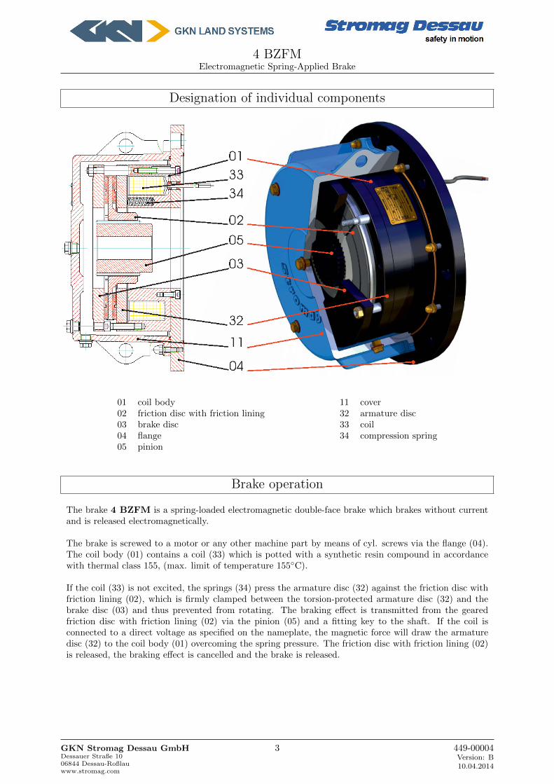
Designation of individual components
01 coil body 11 cover02 friction disc with friction lining 32 armature disc03 brake disc 33 coil04 flange 34 compression spring05 pinion
Brake operation
The brake 4 BZFM is a spring-loaded electromagnetic double-face brake which brakes without currentand is released electromagnetically.
The brake is screwed to a motor or any other machine part by means of cyl. screws via the flange (04).The coil body (01) contains a coil (33) which is potted with a synthetic resin compound in accordancewith thermal class 155, (max. limit of temperature 155◦C).
If the coil (33) is not excited, the springs (34) press the armature disc (32) against the friction disc withfriction lining (02), which is firmly clamped between the torsion-protected armature disc (32) and thebrake disc (03) and thus prevented from rotating. The braking effect is transmitted from the gearedfriction disc with friction lining (02) via the pinion (05) and a fitting key to the shaft. If the coil isconnected to a direct voltage as specified on the nameplate, the magnetic force will draw the armaturedisc (32) to the coil body (01) overcoming the spring pressure. The friction disc with friction lining (02)is released, the braking effect is cancelled and the brake is released.
GKN Stromag Dessau GmbHDessauer Straße 1006844 Dessau-Roßlauwww.stromag.com
3 449-00004Version: B10.04.2014

4 BZFMElectromagnetic Spring-Applied Brake
X Micro Switch
Optional availability, inboard proving switch, one common contact, one normally open contact andone normally closed contact.This can be interlocked with motor contactor for parking brake duty, i.e. brake release before startingmotor.
X Brake termination
Three standard versions:
• Flying leads usually 1,5 meter long, axial with a cable bushing and radial through cable glandin flange.
• IP 66 terminal box, for easy connection and removal, at execution with terminal box the brakecomplies with protection IP66!
• Versions for AC supply with built-in full wave or half wave rectification inside the terminalbox.
X Emergency release by means of emergency release screws
For mechanical release in case of emergency or for the adjustment of the system emergency releasescrews are available.
X Flange to IEC
Manufactured to suit your motor on B-side to our brake with IEC connection dimensions.
X Standstill heaters
Inboard standstill heaters can be provided.
X Speedometer installation
If a speedometer connection is required for the brake, the brake cover is provided with connect-ing bores in accordance with ”Euro dimension”. The type of protection only maintains when thespeedometer is rigidly connected to the cover by means of a flange gland which is sealed by roundring.
X Special Surface Finishes
All components are surface finished with a special surface protection against abrasive environment;e.g. against saline atmosphere on deck, etc.
GKN Stromag Dessau GmbHDessauer Straße 1006844 Dessau-Roßlauwww.stromag.com
4 449-00004Version: B10.04.2014
4 BZFMElectromagnetic Spring-Applied Brake
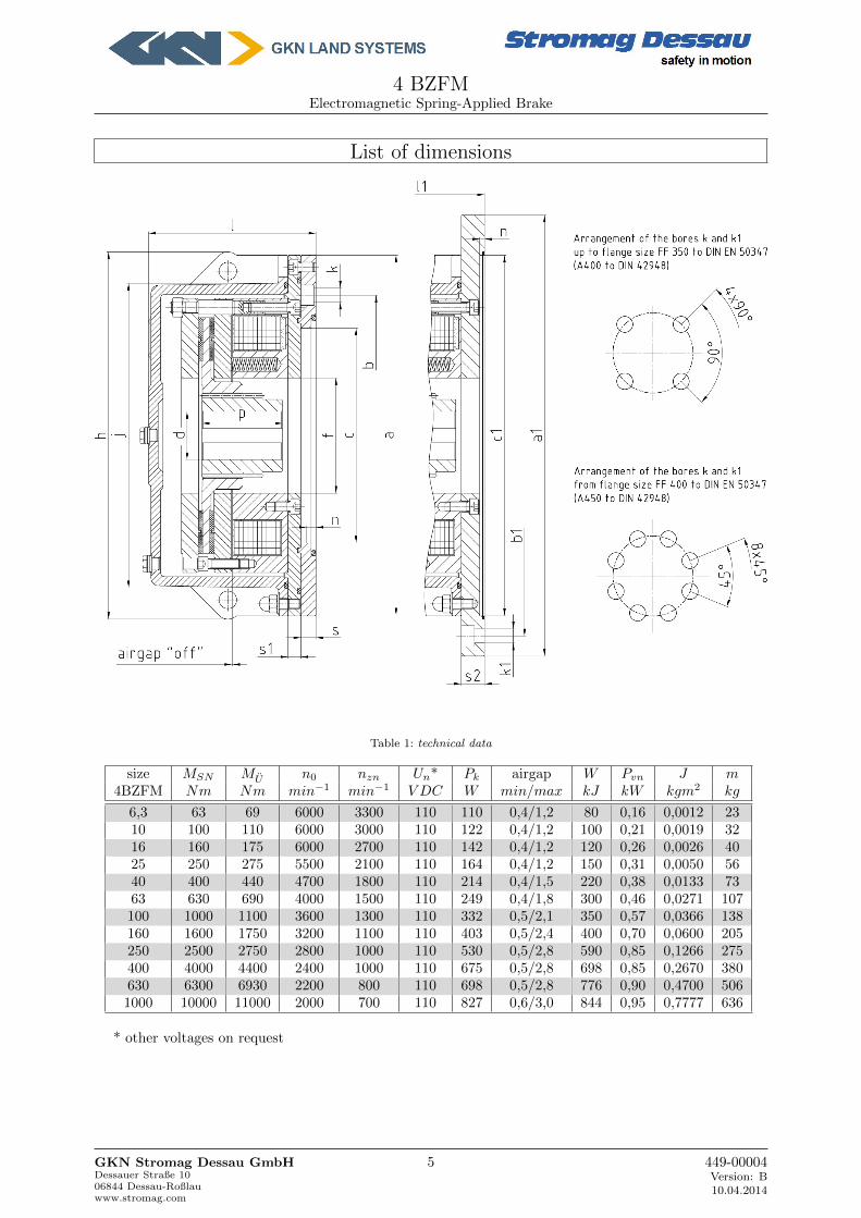
List of dimensions
Table 1: technical data
size MSN MU n0 nzn Un* Pk airgap W Pvn J m4BZFM Nm Nm min−1 min−1 V DC W min/max kJ kW kgm2 kg
6,3 63 69 6000 3300 110 110 0,4/1,2 80 0,16 0,0012 2310 100 110 6000 3000 110 122 0,4/1,2 100 0,21 0,0019 3216 160 175 6000 2700 110 142 0,4/1,2 120 0,26 0,0026 4025 250 275 5500 2100 110 164 0,4/1,2 150 0,31 0,0050 5640 400 440 4700 1800 110 214 0,4/1,5 220 0,38 0,0133 7363 630 690 4000 1500 110 249 0,4/1,8 300 0,46 0,0271 107100 1000 1100 3600 1300 110 332 0,5/2,1 350 0,57 0,0366 138160 1600 1750 3200 1100 110 403 0,5/2,4 400 0,70 0,0600 205250 2500 2750 2800 1000 110 530 0,5/2,8 590 0,85 0,1266 275400 4000 4400 2400 1000 110 675 0,5/2,8 698 0,85 0,2670 380630 6300 6930 2200 800 110 698 0,5/2,8 776 0,90 0,4700 5061000 10000 11000 2000 700 110 827 0,6/3,0 844 0,95 0,7777 636
* other voltages on request
GKN Stromag Dessau GmbHDessauer Straße 1006844 Dessau-Roßlauwww.stromag.com
5 449-00004Version: B10.04.2014
4 BZFMElectromagnetic Spring-Applied Brake
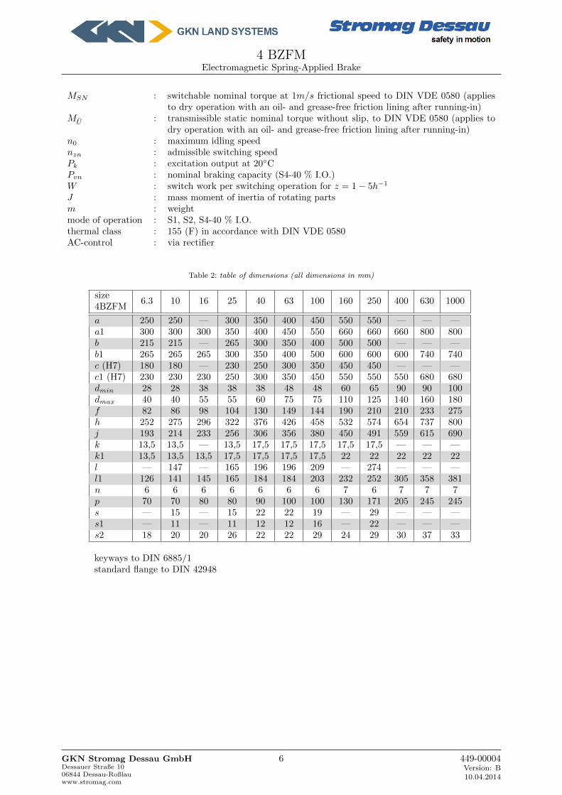
MSN : switchable nominal torque at 1m/s frictional speed to DIN VDE 0580 (appliesto dry operation with an oil- and grease-free friction lining after running-in)
MU : transmissible static nominal torque without slip, to DIN VDE 0580 (applies todry operation with an oil- and grease-free friction lining after running-in)
n0 : maximum idling speednzn : admissible switching speedPk : excitation output at 20◦CPvn : nominal braking capacity (S4-40 % I.O.)W : switch work per switching operation for z = 1 − 5h−1
J : mass moment of inertia of rotating partsm : weightmode of operation : S1, S2, S4-40 % I.O.thermal class : 155 (F) in accordance with DIN VDE 0580AC-control : via rectifier
Table 2: table of dimensions (all dimensions in mm)
size4BZFM
6.3 10 16 25 40 63 100 160 250 400 630 1000
a 250 250 — 300 350 400 450 550 550 — — —a1 300 300 300 350 400 450 550 660 660 660 800 800b 215 215 — 265 300 350 400 500 500 — — —b1 265 265 265 300 350 400 500 600 600 600 740 740c (H7) 180 180 — 230 250 300 350 450 450 — — —c1 (H7) 230 230 230 250 300 350 450 550 550 550 680 680dmin 28 28 38 38 38 48 48 60 65 90 90 100dmax 40 40 55 55 60 75 75 110 125 140 160 180f 82 86 98 104 130 149 144 190 210 210 233 275h 252 275 296 322 376 426 458 532 574 654 737 800j 193 214 233 256 306 356 380 450 491 559 615 690k 13,5 13,5 — 13,5 17,5 17,5 17,5 17,5 17,5 — — —k1 13,5 13,5 13,5 17,5 17,5 17,5 17,5 22 22 22 22 22l — 147 — 165 196 196 209 — 274 — — —l1 126 141 145 165 184 184 203 232 252 305 358 381n 6 6 6 6 6 6 6 7 6 7 7 7p 70 70 80 80 90 100 100 130 171 205 245 245s — 15 — 15 22 22 19 — 29 — — —s1 — 11 — 11 12 12 16 — 22 — — —s2 18 20 20 26 22 22 29 24 29 30 37 33
keyways to DIN 6885/1standard flange to DIN 42948
GKN Stromag Dessau GmbHDessauer Straße 1006844 Dessau-Roßlauwww.stromag.com
6 449-00004Version: B10.04.2014

4 BZFMElectromagnetic Spring-Applied Brake
Optional Accessories
GKN Stromag Dessau GmbHDessauer Straße 1006844 Dessau-Roßlauwww.stromag.com
7 449-00004Version: B10.04.2014
4 BZFMElectromagnetic Spring-Applied Brake
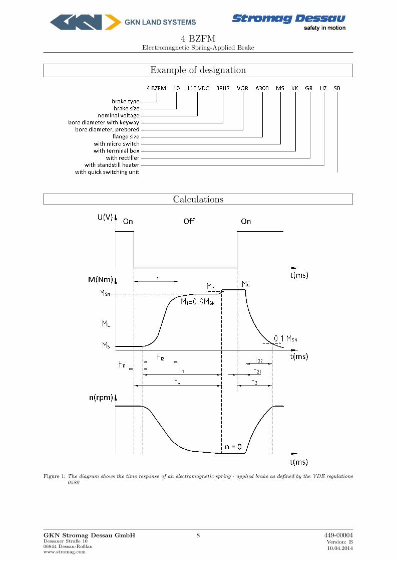
Example of designation
Calculations
Figure 1: The diagram shows the time response of an electromagnetic spring - applied brake as defined by the VDE regulations0580
GKN Stromag Dessau GmbHDessauer Straße 1006844 Dessau-Roßlauwww.stromag.com
8 449-00004Version: B10.04.2014
4 BZFMElectromagnetic Spring-Applied Brake
M1 = switchable torque [Nm]
The switchable (dynamic) torque is the torque which can be transmitted by a brake under slip conditiondepending on the friction coefficient and at working temperature. (M1 = 0, 9MSN )
M3 = synchronization torque [Nm]
The synchronization torque is the torque which arises for a short time after finishing the switching process .
MU = transmissible torque [Nm]
The transmissible (static) torque is the max. torque that can be applied to a brake without the risk ofslipping.
MSN = switchable nominal torque [Nm]
The switchable nominal torque is the dynamic torque as stated in the catalogue at a frictional speed of 1m/sec.
ML = load torque [Nm]
+ML for acceleration, −ML for deceleration. The load torque should always be considered with relativesafety factors.
M5 = no - load torque (drag torque) [Nm]
The no - load torque is the torque which the brake transmits at working temperature when free running.
MA = decelerating torque [Nm]
The decelerating torque results from the addition (substraction for lifting gear during lowering) of theswitchable torque and load torque.
Operation times
The operation times shown in the diagram are based on the example of a brake actuated by loss of electricalcurrent. The basic characteristic is also applicable to brakes with alternate methods of operation.
The time delay t11 is the time from the instant of de - energization (actuation) to the commencementof the torque build - up (of no importance for d.c. switching). The torque build - up time t12 is the timefrom the commencement of torque build - up to the attainment of 90% of the switchable nominal torqueMSN . The switching time t1 is the sum of the time delay and torque build - up time:
t1 = t11 + t12
The time delay t21 is the time from energization (actuation) to the commencement of the torque will decrease.The fall time t22 is the time from the commencement of the torque decrease to 10% of the switchable nominalbrake torque MSN . The switching time t2 is the sum of the time delay and the fall time:
t2 = t21 + t22
To decrease the switching times of electromagnetic spring - applied brakes, special switching is required.Please ask for particular information. The switching times stated in the dimensional tables apply to d.c.switching, working temperature and nominal voltage without special switching techniques.
GKN Stromag Dessau GmbHDessauer Straße 1006844 Dessau-Roßlauwww.stromag.com
9 449-00004Version: B10.04.2014

4 BZFMElectromagnetic Spring-Applied Brake
Nomenclature
AR cm2 Friction surface
m kg Mass
Q Joule(J) Heat quantity
Qh Watt(W ) Heat per hour
ckJ
kgKSpecific heat steel c = 0, 46
kJ
kgKcast iron c = 0, 54
kJ
kgK
n rpm Speed
tA s Braking time
tS s Slipping time
Mass moment of inertia J [kgm2]
The mass moment of inertia J stated in the formula is the total mass moment of inertia of all the massesto be retarded referred to the brake.
Reduction of moments of inertia
The reduction of moments of inertia is calculated from the formula
J1 = J2 ∗ (n2
n1)2 [kgm2]
Moments of inertia of linear masses
The equivalent moment of inertia JErs for a linear mass m and a velocity v referred to the brake speed nis calculated from the formula
JErs = 91 ∗m(v
n)2 [kgm2]
[v = m/s] [n = rpm] [m = kg]
Torque considerations for the brake
The mean torque of the driving or driven machine may be calculated from
M = 9550 ∗ P
n[Nm]
[P = kW ] [n = rpm]
If the system includes gearing, all torques must be referred to the brake shaft. Depending on the typeand functioning of the driving or driven machine resp. shock and peak loads are an important factor forthe determination of brake sizes. If precise deceleration times are required a sufficient decelerating torquemust already been taken into account when selecting the brake size on the torque rating. Considering theload torque direction, the following switchable nominal torque MSN of a brake is attained (+ML for liftingdevices when lowering).
MSN = MA ±ML
GKN Stromag Dessau GmbHDessauer Straße 1006844 Dessau-Roßlauwww.stromag.com
10 449-00004Version: B10.04.2014
4 BZFMElectromagnetic Spring-Applied Brake
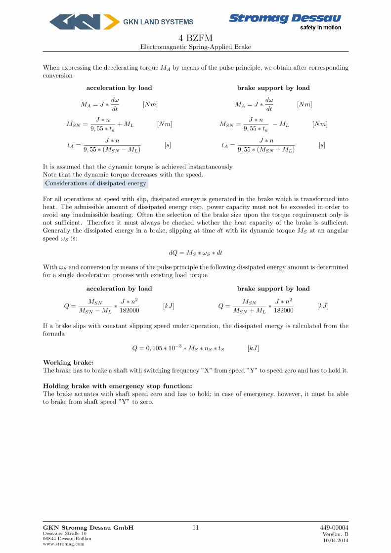
When expressing the decelerating torque MA by means of the pulse principle, we obtain after correspondingconversion
acceleration by load
MA = J ∗ dω
dt[Nm]
MSN =J ∗ n
9, 55 ∗ ta+ ML [Nm]
tA =J ∗ n
9, 55 ∗ (MSN −ML)[s]
brake support by load
MA = J ∗ dω
dt[Nm]
MSN =J ∗ n
9, 55 ∗ ta−ML [Nm]
tA =J ∗ n
9, 55 ∗ (MSN + ML)[s]
It is assumed that the dynamic torque is achieved instantaneously.Note that the dynamic torque decreases with the speed.
Considerations of dissipated energy
For all operations at speed with slip, dissipated energy is generated in the brake which is transformed intoheat. The admissible amount of dissipated energy resp. power capacity must not be exceeded in order toavoid any inadmissible heating. Often the selection of the brake size upon the torque requirement only isnot sufficient. Therefore it must always be checked whether the heat capacity of the brake is sufficient.Generally the dissipated energy in a brake, slipping at time dt with its dynamic torque MS at an angularspeed ωS is:
dQ = MS ∗ ωS ∗ dt
With ωS and conversion by means of the pulse principle the following dissipated energy amount is determinedfor a single deceleration process with existing load torque
acceleration by load
Q =MSN
MSN −ML∗ J ∗ n2
182000[kJ ]
brake support by load
Q =MSN
MSN + ML∗ J ∗ n2
182000[kJ ]
If a brake slips with constant slipping speed under operation, the dissipated energy is calculated from theformula
Q = 0, 105 ∗ 10−3 ∗MS ∗ nS ∗ tS [kJ ]
Working brake:The brake has to brake a shaft with switching frequency ”X” from speed ”Y” to speed zero and has to hold it.
Holding brake with emergency stop function:The brake actuates with shaft speed zero and has to hold; in case of emergency, however, it must be ableto brake from shaft speed ”Y” to zero.
GKN Stromag Dessau GmbHDessauer Straße 1006844 Dessau-Roßlauwww.stromag.com
11 449-00004Version: B10.04.2014
4 BZFMElectromagnetic Spring-Applied Brake
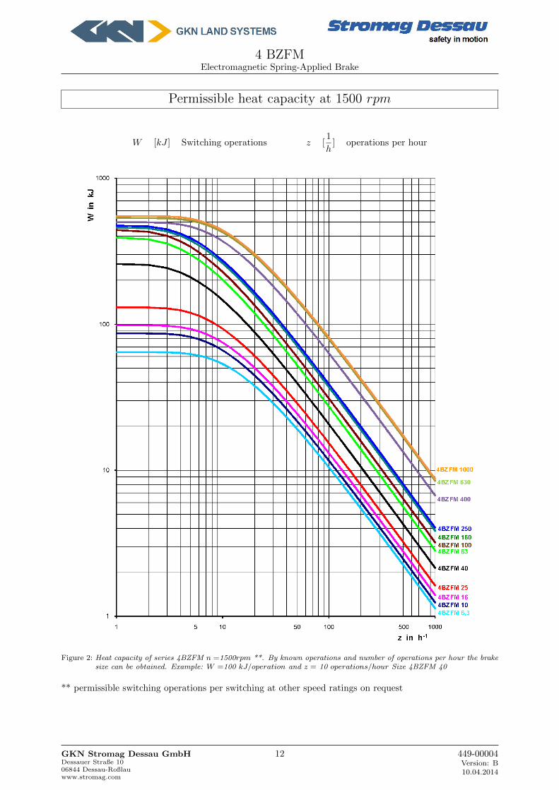
Permissible heat capacity at 1500 rpm
W [kJ ] Switching operations z [1
h] operations per hour
Figure 2: Heat capacity of series 4BZFM n =1500rpm **. By known operations and number of operations per hour the brakesize can be obtained. Example: W =100 kJ/operation and z = 10 operations/hour Size 4BZFM 40
** permissible switching operations per switching at other speed ratings on request
GKN Stromag Dessau GmbHDessauer Straße 1006844 Dessau-Roßlauwww.stromag.com
12 449-00004Version: B10.04.2014
4 BZFMElectromagnetic Spring-Applied Brake
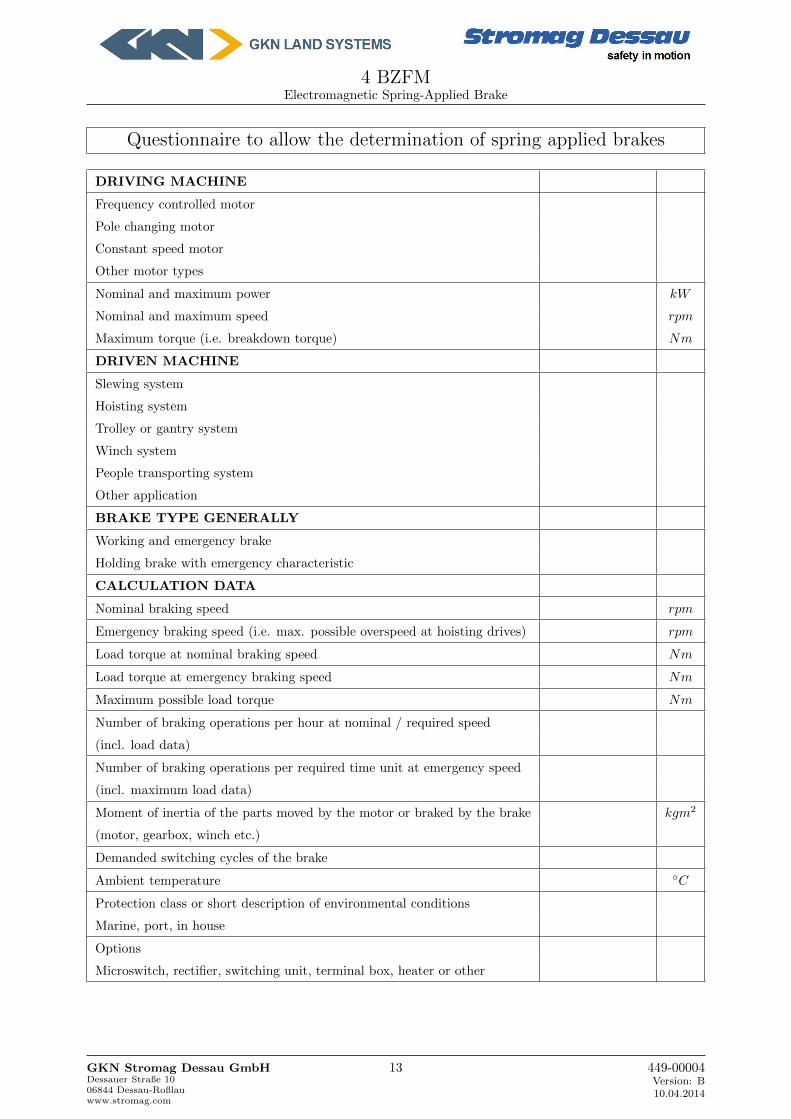
Questionnaire to allow the determination of spring applied brakes
DRIVING MACHINE
Frequency controlled motor
Pole changing motor
Constant speed motor
Other motor types
Nominal and maximum power kW
Nominal and maximum speed rpm
Maximum torque (i.e. breakdown torque) Nm
DRIVEN MACHINE
Slewing system
Hoisting system
Trolley or gantry system
Winch system
People transporting system
Other application
BRAKE TYPE GENERALLY
Working and emergency brake
Holding brake with emergency characteristic
CALCULATION DATA
Nominal braking speed rpm
Emergency braking speed (i.e. max. possible overspeed at hoisting drives) rpm
Load torque at nominal braking speed Nm
Load torque at emergency braking speed Nm
Maximum possible load torque Nm
Number of braking operations per hour at nominal / required speed
(incl. load data)
Number of braking operations per required time unit at emergency speed
(incl. maximum load data)
Moment of inertia of the parts moved by the motor or braked by the brake kgm2
(motor, gearbox, winch etc.)
Demanded switching cycles of the brake
Ambient temperature ◦C
Protection class or short description of environmental conditions
Marine, port, in house
Options
Microswitch, rectifier, switching unit, terminal box, heater or other
GKN Stromag Dessau GmbHDessauer Straße 1006844 Dessau-Roßlauwww.stromag.com
13 449-00004Version: B10.04.2014

GKN Land Systems© 2014PO Box 55,Ipsley House,Ipsley Church Lane,Redditch,Worcestershire B98 0TLP: +44 (0)1527 517 715
GKN Stromag Dessau GmbH
safety in motion Stromag Dessau
Dessauer Str. 1006844 Dessau-RoßlauP: +49 (340) 2190-203F: +49 (340) [email protected]
The GKN Stromag Dessau GmbHis a company of GKN Land Systems
Find out more about GKN Stromagglobal trade representatives
GKN
LS
15 G
B 0
414
SPM
1-0
,1