4 cee soa architecture - maxwell.vrac.puc-rio.br
TRANSCRIPT

CEE SOA Architecture 70
4 CEE SOA Architecture
This chapter will present the CEE Architecture and its main components.
The approach of this chapter starts with the description of the architectural layers
of the solution, followed by the description of the main services and components
description that implement the SOA model presented in the previous chapter.
Further details about the architecture, its services and components are presented
in Appendix A.
4.1. CEE Architecture Layers
CEE aims to provide a multi-user collaborative environment for the
execution, control and visualization of engineering simulations. Thus, it is
necessary to base on solid distributed technologies as well as provide some
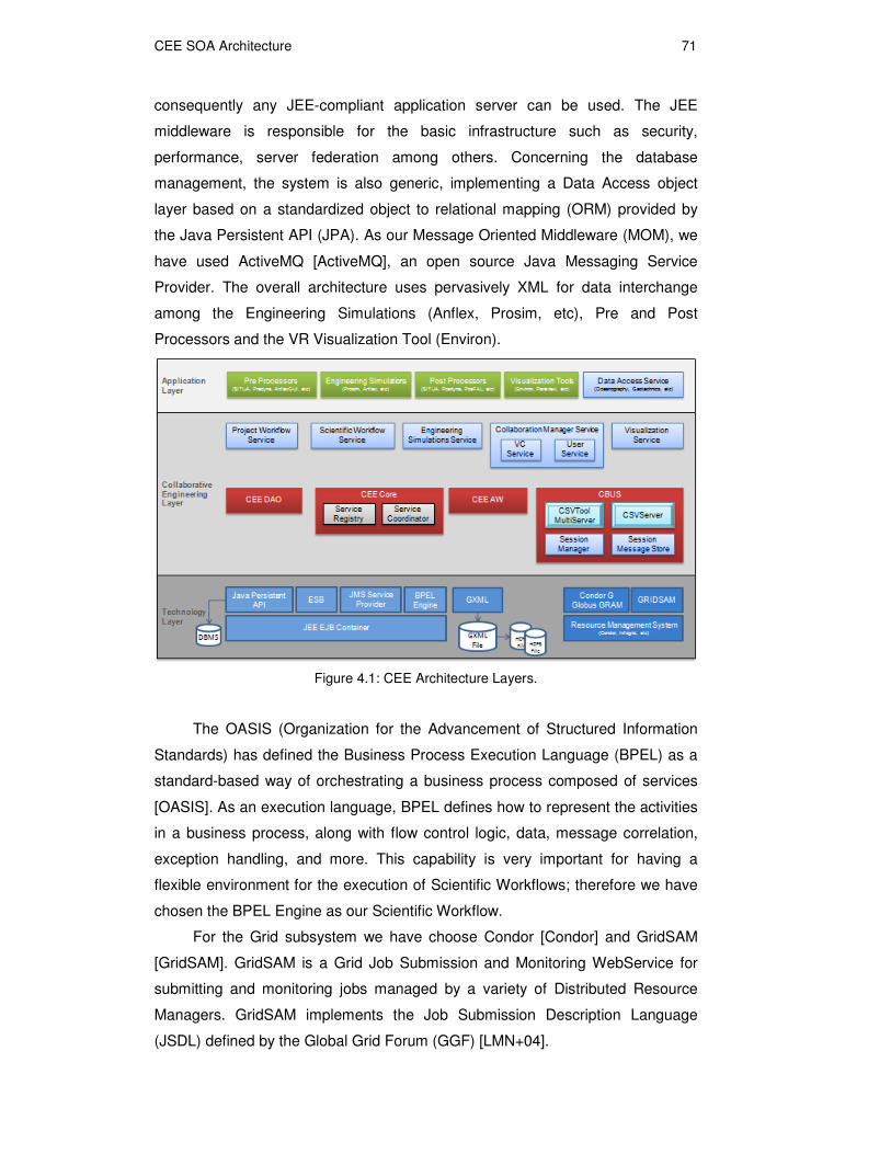
CSCW services to its users. We can distinguish three main layers in the overall
architecture (Figure 4.1): a technology layer, a collaborative engineering layer
and an application layer. The technology layer refers to the basic Information
Technology (IT) infrastructure selected for implementing the basic services of
CEE. The collaborative engineering layer comprises all the necessary
components to enable the execution of an engineering simulation and the
visualization of its results in a collaborative session. The application layer
comprises all the end-user applications that will benefit from the CEE
collaborative resources.
4.1.1. Technology Layer
CEE requires a solid infrastructure to provide security, persistence,
transactions support, scalability and performance. We have chosen the JEE
(Java Enterprise Edition) standard [JEESun] as the technology infrastructure for
this research project. It saves us from implementing infrastructure and system-
specific code, besides allowing us to base on open specifications and
components. This technology makes our system vendor-independent, and
CEE SOA Architecture 71
consequently any JEE-compliant application server can be used. The JEE
middleware is responsible for the basic infrastructure such as security,
performance, server federation among others. Concerning the database
management, the system is also generic, implementing a Data Access object
layer based on a standardized object to relational mapping (ORM) provided by
the Java Persistent API (JPA). As our Message Oriented Middleware (MOM), we
have used ActiveMQ [ActiveMQ], an open source Java Messaging Service
Provider. The overall architecture uses pervasively XML for data interchange
among the Engineering Simulations (Anflex, Prosim, etc), Pre and Post
Processors and the VR Visualization Tool (Environ).
Figure 4.1: CEE Architecture Layers.
The OASIS (Organization for the Advancement of Structured Information
Standards) has defined the Business Process Execution Language (BPEL) as a
standard-based way of orchestrating a business process composed of services
[OASIS]. As an execution language, BPEL defines how to represent the activities
in a business process, along with flow control logic, data, message correlation,
exception handling, and more. This capability is very important for having a
flexible environment for the execution of Scientific Workflows; therefore we have
chosen the BPEL Engine as our Scientific Workflow.
For the Grid subsystem we have choose Condor [Condor] and GridSAM
[GridSAM]. GridSAM is a Grid Job Submission and Monitoring WebService for
submitting and monitoring jobs managed by a variety of Distributed Resource
Managers. GridSAM implements the Job Submission Description Language
(JSDL) defined by the Global Grid Forum (GGF) [LMN+04].
CEE SOA Architecture 72
Using GridSAM to execute jobs on a Grid (in our case, Condor) gives us
transparency of the underlying Grid scheduler. Scientists only need to define the
JSDL for their jobs once and not worry about which scheduler is used now or at
any point in the future.
4.1.2. Collaborative Engineering Layer
The collaborative engineering layer is the most important part of the overall
system, and has been designed taking into account the CEE main components
presented in Chapter 1. The system is divided into several modules, seamlessly
integrated. CEE Core is composed by a collection of collaboration tools,
providing services like shared spaces, access control, floor management, and
integration for both synchronous and asynchronous communication through the
use of a Collaboration Bus (CBUS). CBus is an infrastructure for communication
based on the Java Message Service (JMS) Provider and the Enterprise Service
Bus (ESB) available on the technology layer. The CEE Awareness Service
(AWS) is service mechanism providing group awareness for the CEE
components.
There are a lot of services in this layer providing collaboration support to
CEE applications, further details are presented later in this chapter. The VR
Visualization Service and the Collaboration Manager Service are the most
important components. They use the CEE Core, CEE AWS and CEE CBUS
components to create a collaborative visualization tool to allow the users to
collaboratively visualize the results of an engineering simulation in an immersive
or desktop environment.
4.2. Application Layer
The engineering applications supported by the CEE, are in the Application
Layer. It can be generically divided in four different components: Pre and Post
Processors, Engineering Simulators (Anflex [MGJ95], Prosim [JE94]), Data
Access Services and VR Visualization Tools. One example of VR Visualization
tool is Environ [RCW+09], which was developed to visualize massive CAD
models and engineering simulations in immersive environments (VR and
Desktop)
CEE SOA Architecture 73
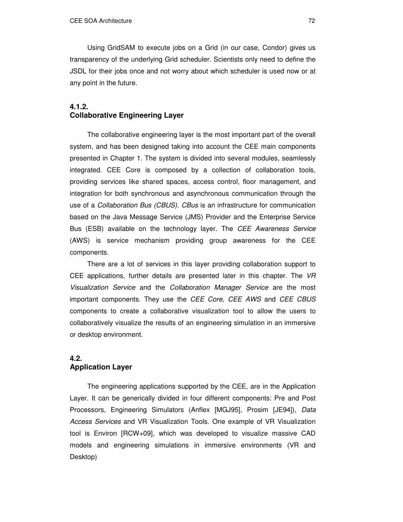
Figure 4.2: CEE Detailed SOA Architecture.
CEE has a client-server architecture (Figure 4.2), where the CEE-server is
deployed in a JEE Application Server (Glassfish in our case) which allows better
scalability and automatic transaction control. The CEE main services reside in
the Application Server where a Service Registry is used to record all available
services present in the CEE clients. For example the CEE VR Visualization tool,
Environ, should be available on a CEE client machine allowing users to
participate in a Collaborative Visualization Session, controlled by the Service
Coordinator.
The features of JAX-WS [JEESun] platform enable the publication of a
WebService interface for each Session Bean, so that the remote clients are able
to request services through the interface. On the server, that’s the case of
Service Coordinator, Service Registry and Collaboration Manager Service. On
the client, Environ Service, CSVTool Service, and Engineering Simulation
Services (Anflex Service, TPN Service, Prosim Service, etc). Those services will
be described in the next section.

CEE SOA Architecture 74
4.2.1. CEE Client Services
The services on the client machine are designed basically to manage and
control the execution of the target application locally, which usually does not have
any collaboration support. In order to make them collaboration-unaware
applications, a software infrastructure is provided by the CEE Server and its
associated services running on server and client machines.
The User Service is responsible to registry user information and the
availability of the other services on the client machine using the Service Registry
WebServices interface.
Environ Service, for example, is the service responsible for creating a
mechanism that allows the communication of the VR Visualization tool, in our
case Environ, running on a client machine and the Collaboration Manager
Service that runs on the server. Environ Service run as a daemon process and
whenever it receives a command to start a session on the client it creates a
proxy, Environ Proxy, which acts as a mediator between the Environ and the
Collaboration Manager Service. Following this pattern Environ can receive and
send commands to other users through Environ Proxy, transforming Environ into
a collaboration-unaware application, which is essential for the CEE as a CPSE.
Further details are given in section Error! Reference source not found..
Analogously the same happens with the CSVTool Service and the
Engineering Simulations Services (Anflex Service, Prosim Service, etc), which
are detailed in the next sections.
Communication between users and the CEE server will be accomplished
through the CEE Portal, which accesses the Service Coordinator through its
WebServices interface and calls for some service, such as the creation of a
Collaborative Visualization session for visualizing results. More details can be
seen on the section about creating a VC and VRV session (sections Error!
Reference source not found. and Error! Reference source not found.).
4.2.2. CEE Server Services and Components
Some of the services executing on the server are implemented as EJB
(Enterprise Java Beans) components and exported as WebServices for servicing
remote communications from the clients. The main components and services on
the server are: Service Coordinator, implemented as an EJB with an exported

CEE SOA Architecture 75
WebService interface; Service Registry, like Service Coordinator is also
implemented as an EJB and have a WebService interface. The other services
are implemented as WebServices.
4.2.2.1.Service Coordinator
The Service Coordinator (SC) is a centralized service bridging clients to
servers and providing deployment-wide services within a cluster-deployed CEE
instance. The Service Coordinator is a singleton within a CEE deployment, and
thus manages information and services that are relevant to a CEE deployment as
a whole. Its primary responsibilities include:
� acting as a ‘well known’ CEE access point for clients;
� acting as a gatekeeper handling authentication and authorization of
clients accessing the CEE system. The SC will use an LDAP
(Lightweight Directory Access Protocol) [LDAP] service to manage
client-related authentication and authorization information;
� acting as an environment manager for the CEE deployment as a
whole.
Service Coordinator is responsible for creating and controlling a CEE
Session, which is a composition of different kinds of sessions available: a project
workflow session, a scientific workflow session, a visualization session and a
videoconference session. Each client’s interaction with the server initiates with
the creation of a specific session where the interactions take place. Depending
on the course of actions in the client-server interaction, the CEE Session will be
composed of those different sessions.
The CEE client can start a Project workflow session to import project
information from an Enterprise Resource Planning system, such as SAP [SAP] to
an internal project representation properly adapted to CEE functionalities. To run
an engineering simulation the client starts a scientific workflow session,
assembles an engineering workflow using scientific workflow designer, and
submit the workflow as a job for execution on a Grid Computing infrastructure
provided by the CEE server. At the end of the execution of a scientific workflow
session, a visualization session can be created to allow the client to inspect the
results of the simulation. During the whole process the client can start a
videoconference session at any time to add support for audio/video
communication with other clients. This sequence of actions is explained at the
end of Chapter 3 and will be seen in the case studies of Chapter 5.
CEE SOA Architecture 76
The Service Coordinator can be invoked remotely to send commands to a
CEE Session. This is what happens when the user access the CEE portal to
create a new CEE Session or to join an existing one. All the commands sent from
the CEE client to Service Coordinator are redirected to Session Manager who
manages the CEE Session and coordinates the aggregate functionality added to
it depending on which session was started by the client. For example, the client
can initially start CEE Session requesting the creation of a VC Session to discuss
project details with a remote client. After some discussions they can decide to
start a scientific workflow session to collaboratively create an engineering
workflow that will be scheduled to run on the Grid Computing infrastructure
provided by the CEE Server. In this way, the CEE Session will be a composition
of a ScientificWorkflow Session and a VC Session. If they decide to continue they
can start a VR-Visualization session and see the results.
It is important to mention that a ScientificWorkflow Session, a VC Session,
and a Visualization Session can coexist at the same time in the server for the
client that are participating in the collaboration. On the other hand, the Project
Workflow Session is required to run first, possibly with the support of a VC
Session, to allow the user to create its own project environment to store data
generated during the execution of the project.
4.2.2.2.Collaboration Manager Service
Collaboration Manager Service handles information about logged users in a
collaborative CEE Session. It is responsible for the collaborative session
management, access control policies, and behavior of each participant. One of
the main components of the Collaboration Manager Service is the Session
Manager, which is responsible to manage registered clients on the server and
also coordinate the execution of the VR Visualization Service and the VC Service
when both are selected services to be used in a CEE session. Collaboration
Manager Service is also responsible for initiating the JMS Service Provider, in
order to start the Collaboration Bus, the communication mechanism used by the
collaborative session users.
VR Visualization Service is responsible for giving support for the
Visualization Session execution and for supporting the creation of the
Collaborative Visualization Session together with Collaboration Manager Service.
The VR Visualization Service integrates Environ [RCW+06, RSS+09] as the CEE
VR Visualization tool furnishing the necessary support.

CEE SOA Architecture 77
The VC Service is a videoconference service that integrates CSVTool (see
section Error! Reference source not found.). VC Service responsibility is to
control the evolution of a videoconference session which could occur
simultaneously with a Visualization Session, characterizing a Collaborative
Visualization Session.
The Service Coordinator in conjunction with the Session Manager is
responsible for the creation and controlling of the Collaborative Visualization
Session connecting Environ with any other engineering simulations that wants to
have its results collaboratively visualized by its users.
4.2.2.3. Collaboration Bus Implementation
The CEE-Collaboration Bus is created by the combination of an Enterprise
Service Bus and a Message Oriented Middleware (MOM), with a Java Messaging
ServiceTM (JMS) compliant implementation provided, in our case, by Apache-
ActiveMQ [ActiveMQ].
Remote procedure call (RPC) systems, including Java RMI, are
synchronous – the caller must block and wait until the called method completes
execution, and thus offer no potential for developing loosely coupled enterprise
applications without the use of multiple threads. In other words, RPC systems
require the client and the server to be available at the same time. However, such
tight coupling may not be possible or desired in some applications. MOM
systems provide solutions to such problems. They are based on the
asynchronous interaction model, and provide the abstraction of a message
queue that can be accessed across a network. More generally, MOM is a
category of software for communication in a loosely-coupled, reliable, scalable
and secure manner amongst distributed applications or system. The overall idea
with a MOM is that it acts as message mediator between message senders and
message receivers.
JMS was defined to allow Java application to use enterprise messaging
systems. It provides a common way for Java applications to access such
enterprise messaging systems. Two types of channels are available, a Point-to-
Point (i.e. a single channel per peer), available for peer to peer communications,
and a public-subscribe channel for group communications.
� Point-to-Point (Queue destination): In this model, a message is
delivered from a producer to one consumer. The messages are
CEE SOA Architecture 78
delivered to the destination, which is a queue, and then delivered to
one of the consumers registered for the queue. While any number of
producers can send messages to the queue, each message is
guaranteed to be delivered, and consumed by one consumer. If no
consumers are registered to consume the messages, the queue holds
them until a consumer registers to consume them.
� Publish/Subscribe (Topic destination): In this model, a message is
delivered from a producer to any number of consumers. Messages
are delivered to the topic destination, and then to all active consumers
who have subscribed to the topic. In addition, any number of
producers can send messages to a topic destination, and each
message can be delivered to any number of subscribers. If there are
no consumers registered, the topic destination does not hold
messages unless it has durable subscription for inactive consumers. A
durable subscription represents a consumer registered with the topic
destination that can be inactive at the time the messages are sent to
the topic.
In our implementation, the Collaboration Bus is created by the
Collaboration Manager Service every time a new CEE Session is created. For
that session a topic, with the name of the CEE session is created, to allow group
communication. A queue for every participant in the CEE session is also created
allowing peer to peer communications.
In Section Error! Reference source not found., we give more details
about the usage of the collaboration bus for collaborative visualization with our
VRV, Environ.
4.2.2.4.Scientific Workflow Service
The Scientific Workflow Service is used to create engineering workflows
(comprised of the engineering simulations) and orchestrate the execution of
those workflows using BPEL to describe the workflow and schedules it for
execution on a GCI through the use of the Grid Job Service of the CEE.
4.2.2.5.Project Workflow Service
This service is responsible to help the user import project definition from an
external Enterprise Resource Planning (ERP) system and represent it internally

CEE SOA Architecture 79
in the CEE. It is also responsible to make all the necessary synchronization to
update the external ERP system improving the ERP’s capabilities having a better
estimate of the efforts and costs involved in the actual course of a Large Scale
Engineering Project.
4.2.2.6.Service Registry
Service Registry records the available services in every client machine
connected to the CEE server. The registry stores the URL of each service
available in the client machine, the VR Visualization Service (Environ Service),
the Videoconference Client Service (CSVTool Service) and any Engineering
Simulation Services (Anflex Service, Prosim Service, e.g.).
The Service Registry is consulted by the Service Coordinator to obtain
information about the services that could be called on the client machine
whenever a client requests the creation of a CEE Session. The Service Registry
gives transparency of location for the services that will be invoked by the Service
Coordinator on the client machine whenever a CEE Session is created.
In the next sections more details will be presented about the execution of
the different types of section that the clients can invoke on the CEE server.

CEE SOA Architecture 80
Figure 4.3: Registering available services in Service Registry.
4.2.3. Registration of Services
Before using the CEE server, the CEE client must authenticate on the CEE
Server. The authentication process is not addressed in this thesis, once there are
many standard ways of doing this. Particularly for JEE Application Server there is
a standardized process available using the JAAS (Java Authentication and
Authorization Service) [NT06].
Once authenticated in the server, the CEE client should register the
services available on its client machine (Figure 4.3). The components
responsible for this registration are the User Service, Service Registry and
Collaboration Manager Service. The User Service is the service utilized by the
CEE Client application. The sequence of actions for the registration process is
described as follows:
1. The Client, through the User Service, invokes Service Registry
WebServices interface to register user information, and the available local
CEE SOA Architecture 81
services: Environ Service, CSVTool Service and Engineering Simulation
Services. This information is static and dependent on each machine
configuration, so it can be saved on a local CEE-configuration file and
defined during the installation of the CEE client on the client machine;
2. Upon receiving the user information and the available services the
Service Registry store this information on the Service Repository;
3. In the last step, Service Registry sends the user information to the
Collaboration Manager Service, enabling the user to start a new session
or joining an already started session.
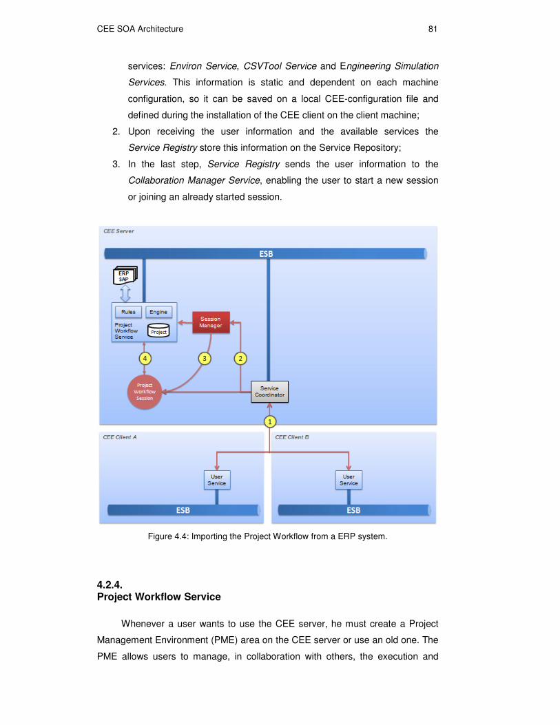
Figure 4.4: Importing the Project Workflow from a ERP system.
4.2.4. Project Workflow Service
Whenever a user wants to use the CEE server, he must create a Project
Management Environment (PME) area on the CEE server or use an old one. The
PME allows users to manage, in collaboration with others, the execution and
CEE SOA Architecture 82
control of engineering projects, imported from an ERP system such as SAP, and
referred as Project Workflow.
The components responsible for importing a project workflow to a PME are
the User Service, and the Service Coordinator. The User Service is the service
utilized by the CEE Client application. The sequence of actions for importing the
project workflow are described as follows (Figure 4.4):
1. The Client, through the User Service, invokes Service Coordinator
WebServices interface to request the importation of a Project Workflow to
a PME;
2. Service Coordinator sends a request to Session Manager to create a
Project Workflow Session and passes all the information about the project
that will be imported from the ERP system;
3. Session Manager asks the Project Workflow Service to create the Project
Workflow Session and then send the ID of the session to the Service
Coordinator;
4. Project Workflow Session imports the project workflow into the CEE
Project Management Environment and the Service Coordinator notifies
the client about the creation of the project.
4.2.5. Scientific Workflow Service
In the Scientific Workflow Environment, the services representing the
Engineering Simulators and Grid Computing Infrastructure have WebServices
interface which allows them to be directly executed on a BPEL engine. To
properly define the input parameters of the simulators the users will possibly
have to execute the Pre-processors for assembling the input data for each
simulation case (Figure 4.6).
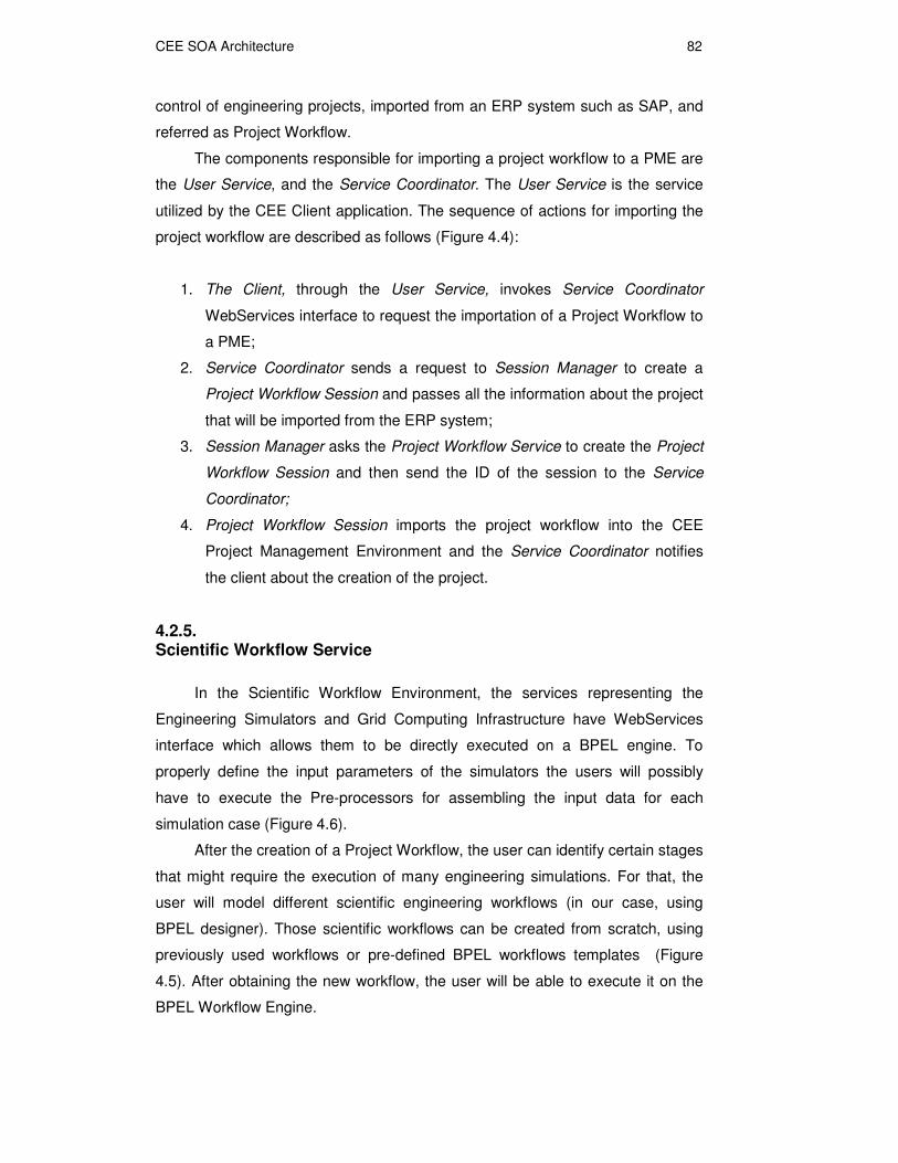
After the creation of a Project Workflow, the user can identify certain stages
that might require the execution of many engineering simulations. For that, the
user will model different scientific engineering workflows (in our case, using
BPEL designer). Those scientific workflows can be created from scratch, using
previously used workflows or pre-defined BPEL workflows templates (Figure
4.5). After obtaining the new workflow, the user will be able to execute it on the
BPEL Workflow Engine.
CEE SOA Architecture 83
Figure 4.5: Modeling and Executing a Scientific Workflow.
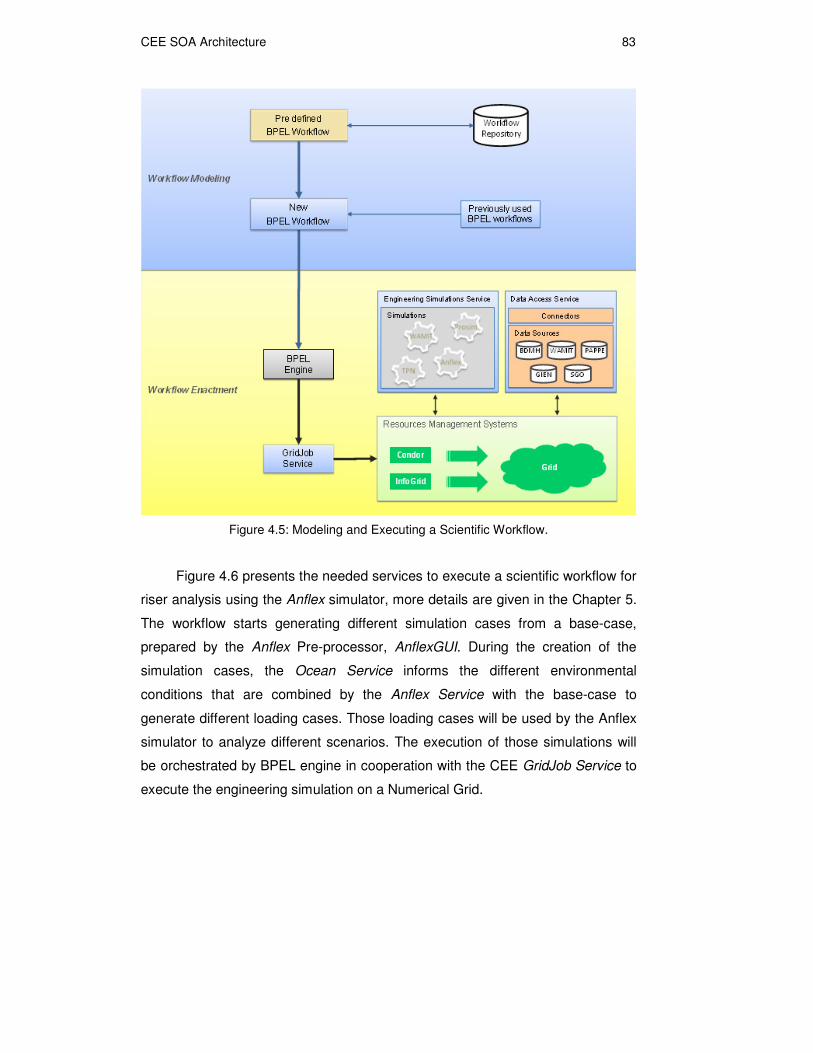
Figure 4.6 presents the needed services to execute a scientific workflow for
riser analysis using the Anflex simulator, more details are given in the Chapter 5.
The workflow starts generating different simulation cases from a base-case,
prepared by the Anflex Pre-processor, AnflexGUI. During the creation of the
simulation cases, the Ocean Service informs the different environmental
conditions that are combined by the Anflex Service with the base-case to
generate different loading cases. Those loading cases will be used by the Anflex
simulator to analyze different scenarios. The execution of those simulations will
be orchestrated by BPEL engine in cooperation with the CEE GridJob Service to
execute the engineering simulation on a Numerical Grid.

CEE SOA Architecture 84
Figure 4.6: Executing a Scientific Workflow instance in CEE.
The CEE is being constructed in order to allow the management and use of
high-performance computational resources. The integration of CEE and Grid
Resource Management Systems such as Condor [Condor] and InfoGrid
[LMC+05], can be done though the GridJob Service. We choose the GridSAM as
our Grid JobService.
4.2.6. Videoconference Service
CSVTool (Collaboration Supported by Video) [PRS+03, LKR+07] was
developed as a multiplatform videoconferencing tool focused on audio and video
communication with support to cooperation (such as desktop image
transmission) and coordination features like management of multiple VC
sessions, individual control of transmitted and received audio and video streams

CEE SOA Architecture 85
for each participant, and the possibility of creating new custom types of video
conference sessions. CSVTool is implemented with JMF (Java Media
Framework) [JMFSun], which employs a high-level abstraction for codec and
transmission protocol details. It was designed with the goal of providing
integrated multimedia communication to collaborative applications, but can also
be used as an independent videoconferencing tool.
Figure 4.7: Starting a VC session in CEE.
The VC Service initiates the CSVTool Multiserver [LKR+07] in the server,
which will handle information of multiple different videoconference sessions,
allowing CEE users to choose which videoconference they might join, or decide
to create a new one, according to each VC session access policies. Each VC
session is managed by the CSVTool Server created in the server whenever a
new VC session is initiated. In the client, the VC Client Service is responsible for
initiating the CSV Client, which communicates to, and is controlled by, the
CSVTool Server. The CSVTool Client is responsible for managing the audio and
video streams between the VC Session participants creating a point-to-point
communication among all the participants.
CEE SOA Architecture 86
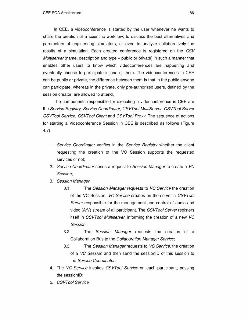
In CEE, a videoconference is started by the user whenever he wants to
share the creation of a scientific workflow, to discuss the best alternatives and
parameters of engineering simulators, or even to analyze collaboratively the
results of a simulation. Each created conference is registered on the CSV
Multiserver (name, description and type – public or private) in such a manner that
enables other users to know which videoconferences are happening and
eventually choose to participate in one of them. The videoconferences in CEE
can be public or private, the difference between them is that in the public anyone
can participate, whereas in the private, only pre-authorized users, defined by the
session creator, are allowed to attend.
The components responsible for executing a videoconference in CEE are
the Service Registry, Service Coordinator, CSVTool MultiServer, CSVTool Server
CSVTool Service, CSVTool Client and CSVTool Proxy, The sequence of actions
for starting a Videoconference Session in CEE is described as follows (Figure
4.7):
1. Service Coordinator verifies in the Service Registry whether the client
requesting the creation of the VC Session supports the requested
services or not;
2. Service Coordinator sends a request to Session Manager to create a VC
Session;
3. Session Manager:
3.1. The Session Manager requests to VC Service the creation
of the VC Session. VC Service creates on the server a CSVTool
Server responsible for the management and control of audio and
video (A/V) stream of all participant. The CSVTool Server registers
itself in CSVTool Multiserver, informing the creation of a new VC
Session;
3.2. The Session Manager requests the creation of a
Collaboration Bus to the Collaboration Manager Service;
3.3. The Session Manager requests to VC Service, the creation
of a VC Session and then send the sessionID of this session to
the Service Coordinator;
4. The VC Service invokes CSVTool Service on each participant, passing
the sessionID;
5. CSVTool Service

CEE SOA Architecture 87
5.1. CSVTool Service creates the CSVTool Proxy passing
information of the VC Session and the JMS – Collaboration Bus.;
5.2. CSVTool Service creates the CSVTool Client ;
6. CSVTool Client connects to CSVTool Server to obtain A/V communication
parameters among participants. CSVTool Server is responsible for the
control of the VC Session participants;
7. CSVTool Client connects all the other CSVTool Clients and create the
RTP A/V streams between them. A/V streams are transmitted between
clients without CSVTool Server participation.
4.2.7. Collaborative Visualization Service
Environ, the CEE–VRV, was adapted to be transformed into a
collaboration-aware application with the support provided by the CEE
collaborative infrastructure. Figure 4.8 demonstrates how Environ was adapted to
be able to send and receive messages from other clients.
4.2.7.1.Collaborative support for Environ
The adaptation follows the Remote Procedure Call mechanism, created in
the former times, as an alternative for distributed computation. The process of
adaptation was made in two levels. In the first level, one instance of Environ
acting as a server connects to many other Environ running as clients. The
Environ server creates a server socket and starts listening the port waiting for
client connections, while the other Environ clients creates a socket and connects
to the Environ server.
For every new client connection, a thread on the Environ server is created
to deal with this new client, and the exchange of commands between that thread
in Environ server and the Environ client can start. This synchronous
communication is very limiting for collaboration purposes.

CEE SOA Architecture 88
Figure 4.8: Environ and its RemoteCommandManager.
To implement the exchange of commands we created the
ComandSerializer component that is in charge of transforming the commands
within Environ into its equivalent serialized form. This serialized form used the
characteristics of the Lua language [IFC96] that is fully integrated into Environ
through a Lua scripting component (Figure 4.8). Another component of the
solution is the RemoteCommandManager who is responsible to send and receive
the serialized commands through a TCP/IP socket network connection. The flow
of commands is depicted as follows:
1 Every command executed by the EnvironCore, or Lua command sent to
Environ from the console, that should be retransmitted, is sent to

CEE SOA Architecture 89
ComandSerializer component who translate the command into a
serialized form;
2 ComandSerializer, upon serializing the command send it to the
RemoteCommandManager whose job is to package the serialized
command in an appropriate message format to allow peer
RemoteCommandManager to deal with those messages in an efficient
manner;
2.1 The message protocol defined consists of a header and tail
demarcating the limits of the message, i.e., the serialized command.
Inside the header, besides information like timestamp and sender
identification, we have two distinct information characterizing the
message itself the message category and the message command.
The categories are, among others: CollaborationCommands,
ConsoleCommands, WebConsoleCommands, AnnotationCommands,
CameraCommands, etc.
2.2 This division in categories allows an efficient treatment because
messages can be discarded according to its category depending on
the state of the Environ peer. For example, for a client running Environ
which is in an offline state, most of the commands could be discarded
except the CollaborationCommands.
3 RemoteCommandManager sends the serialized command package
inside the message format, to all other RemoteCommandManager that
are connected;
4 The RemoteCommandManager peer upon receiving the message, look
into the header to check if it should process it or not;
5 ComandSerializer then receives the message from the socket,
desserialize it and send it for execution in the Scripting Lua component;
6 In the Scripting Lua component the command is then executed locally.
Following this procedure the commands are executed back and forth in the
Environ peers and we can achieve the first level of collaboration, with
synchronous messages.
The second level of integration is a more powerful mechanism once it
extends the types of communications that exists for Environ adding the group
communication mechanism and the peer-to-pear mechanism provided by CEE
Colaboration Bus.
In this second level (Figure 4.8), the Environ Service creates a local
Environ Proxy that talks to the Collaboration Bus and acts as a server for

CEE SOA Architecture 90
Environ, which connects to a server socket on Environ Proxy. This way, all
collaboration communication is tracked by Environ Proxy that sends back those
commands to Environ. On the other way, every command sent by Environ is
resent by Environ Proxy to a topic created for the CEE Session in the
Collaboration Bus or to an specific Queue.
Figure 4.9: Starting a Visualization session in CEE.
4.2.7.2.Environ Service
The Environ Collaborative Session is implemented with the help of a Java
Messaging Service (JMS). The Environ Collaborative Session is controlled by the
CEE service coordinator in conjunction with all Eviron Proxy started on demand
by the each Environ Service on a CEE-client machine that takes part in the CEE
Session.
The components responsible for executing Collaborative Visualization
Session in CEE are the Service Registry, Service Coordinator, Environ Service,
Environ and Environ Proxy. The sequence of actions for the starting a
Collaborative Visualization Session is described as follows (Figure 4.9):

CEE SOA Architecture 91
1. Service Coordinator verifies in the Service Registry whether the client
requesting the creation of the Collaborative Visualization Session
supports the requested services or not;
2. Service Coordinator sends a request to Session Manager to create a
Collaborative Visualization Session;
3. Session Manager:
3.1. The Session Manager requests to Visualization Service the
creation of Collaborative Visualization Session;
3.2. The Session Manager requests the creation of a
Collaboration Bus to the Collaboration Manager Service;
3.3. The Session Manager requests the creation of
Visualization Session to Visualization Service and then send the
sessionID of the session to the Service Coordinator;
4. The Visualization Service invokes Environ Service on each participant,
passing the sessionID;
5. Environ Service
5.1. Environ Service creates the Environ Proxy passing
information of the Visualization Session and the JMS –
Collaboration Bus;
5.2. Environ Service creates the Environ as client connected on
Environ Proxy;
6. Service Coordinator receives commands from the CEE Portal and sends
them to the topic or one of the queues created for the session in the JMS
Collaboration Bus, which means that the commands is sent to all
participants (topic) or to an specific one (queue). Similarly, all participants
can exchange commands among themselves using the Environ Proxies.
In the next chapter we present some usage scenarios where we have
tested the CEE prototype. In those scenarios we emphasize the contribution of
the VR Visualization for the comprehension of the engineering simulation results.