4 combustion of energetic materials...furazan azoxy, tetraazan‐oxide pentalene 9. ... isolated...
TRANSCRIPT
4
Combustion of Energetic gMaterials
Richard A. YetterPenn State Universityy
Princeton‐Combustion Institute 2018 Summer School on Combustion
June 25‐29, 2018Princeton NJPrinceton, NJ
1

Chemical Kinetics and Flame StructureChemical Kinetics and Flame Structure of Energetic Materials
2
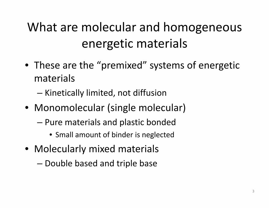
What are molecular and homogeneous lenergetic materials
• These are the “premixed” systems of energetic• These are the premixed systems of energetic materials
Ki ti ll li it d t diff i– Kinetically limited, not diffusion
• Monomolecular (single molecular)– Pure materials and plastic bonded
• Small amount of binder is neglected
• Molecularly mixed materials– Double based and triple base
3
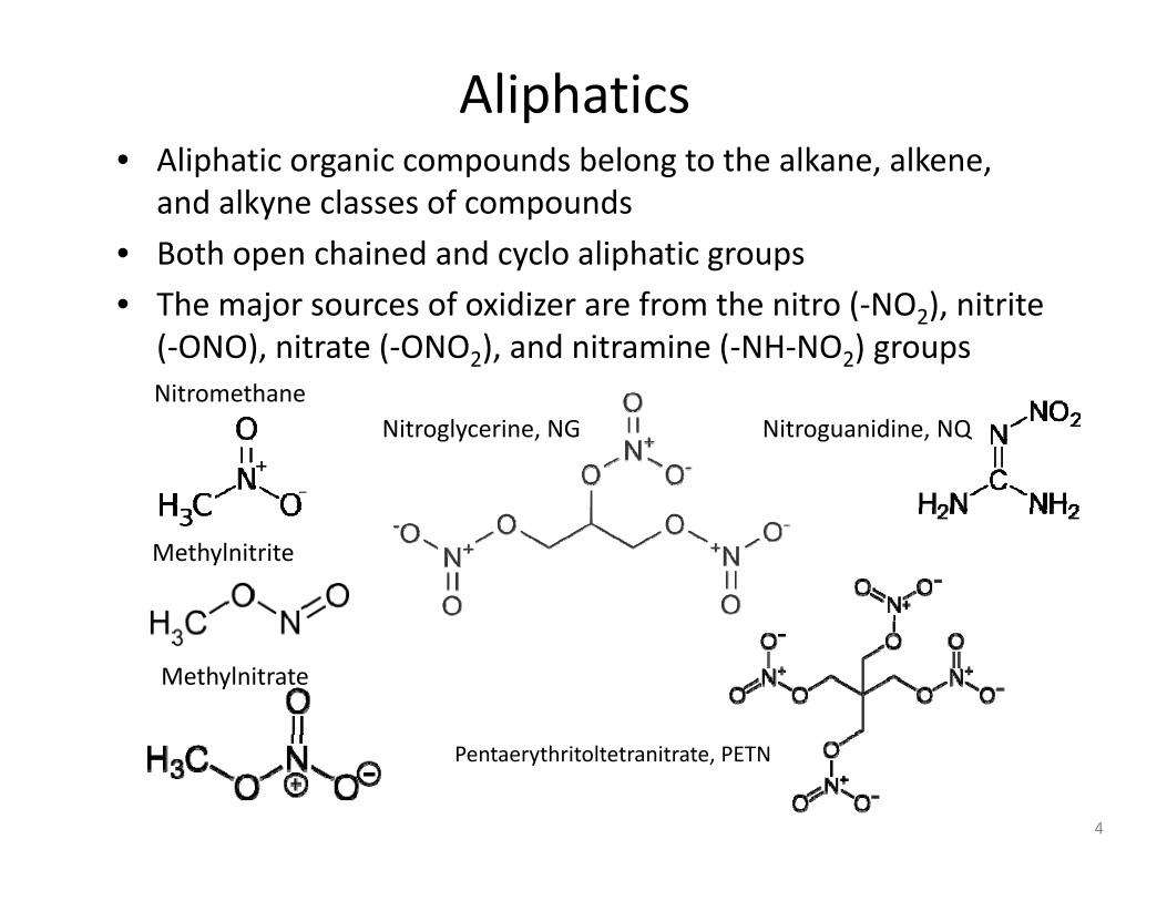
Aliphatics• Aliphatic organic compounds belong to the alkane alkeneAliphatic organic compounds belong to the alkane, alkene,
and alkyne classes of compounds
• Both open chained and cyclo aliphatic groups
• The major sources of oxidizer are from the nitro (‐NO2), nitrite (‐ONO), nitrate (‐ONO2), and nitramine (‐NH‐NO2) groupsNitromethaneNitromethane
Nitroglycerine, NG Nitroguanidine, NQ
Methylnitrite
Methylnitrate
Pentaerythritoltetranitrate, PETN
4

Cycloaliphatics• These are also nitramines• Very commonly used in propellants and explosivesTh ll t fl t I f t th h diff t• They are really not flat. In fact, they can have different configurations, which give different crystal structures, which are different solid phasesp
C l t t th lC l t i th l CyclotetramethyleneTetranitramine, HMX
CyclotrimethyleneTrinitramine, RDX
5

Aromatics• Oxygen added by ‐NO2 groups mainly
Triaminotrinitrobenzene, TATBTrinitrotoluene, TNTTrinitrobenzene, TNB
(The standard for insensitivity)(Good performance and sensitivity, but difficult to make expensive)
Trinitrophenol, Peric Acid Lead styphnate
but difficult to make ‐ expensive)
6

Inorganics• Inorganic compounds do not have hydrocarbon backbonesInorganic compounds do not have hydrocarbon backbones
forming the basis of the molecules• Usually are ionic acids or bases, or salts
P t i hl t KClOA i it t AN NH +NO Potassium chlorate, KClO3Ammonium nitrate, AN, NH4+NO3
‐
(hard to use as a propellant or explosive, but very inexpensive and chlorine free)
(no oxidizer surpasses its burning speed and ease of ignition becomes sensitive with red
Potassium perchlorate, KClO4
Ammonium perchlorate, AP, NH4+ClO4
‐
but very inexpensive, and chlorine free) ease of ignition, becomes sensitive with red phosphorous, can decompose under UV)
(common composite propellant oxidizer)
(can explode alone with strong impact, less prone to decompose under UV than KClO3)
Also azides, e.g., lead azide
7
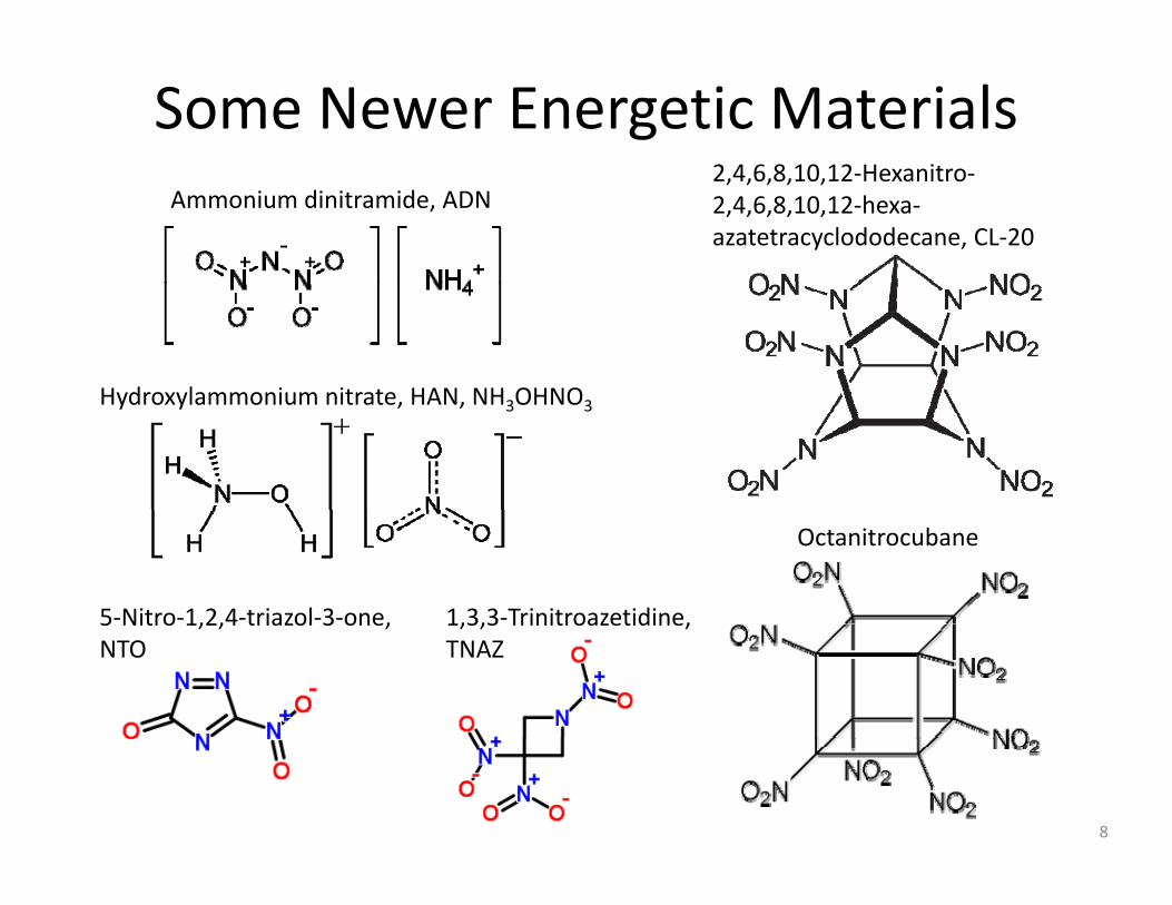
Some Newer Energetic Materials2 4 6 8 10 12 H it
Ammonium dinitramide, ADN2,4,6,8,10,12‐Hexanitro‐2,4,6,8,10,12‐hexa‐azatetracyclododecane, CL‐20
Hydroxylammonium nitrate HAN NH OHNOHydroxylammonium nitrate, HAN, NH3OHNO3
Octanitrocubane
5‐Nitro‐1,2,4‐triazol‐3‐one, 1,3,3‐Trinitroazetidine,5 Nitro 1,2,4 triazol 3 one, NTO
1,3,3 Trinitroazetidine, TNAZ
8
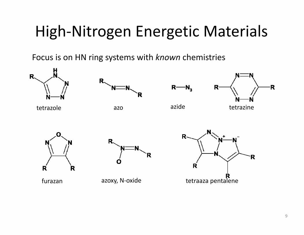
High‐Nitrogen Energetic MaterialsFocus is on HN ring systems with known chemistries
tetrazole azo azide tetrazine
furazan azoxy, N‐oxide tetraaza pentalene
9

High‐Nitrogen Energetics Exhibit Unusual Properties
• Explosive Performance vs Sensitivity rule does not follow.
Properties
DAAF
AAzF, DAAF• High Burn Rates with Low Pressure SensitivitySensitivity(DAATO3.5, 100 atm, 6 cm/s, n=0.275)
DHT
• Detonate despite having no oxygenDHT/DAAT
• Burn rapidly without visible flamep yDHT/BTATz
• High Hydrogen alsoDHT/TAGzTDHT/TAGzT BTATz
10
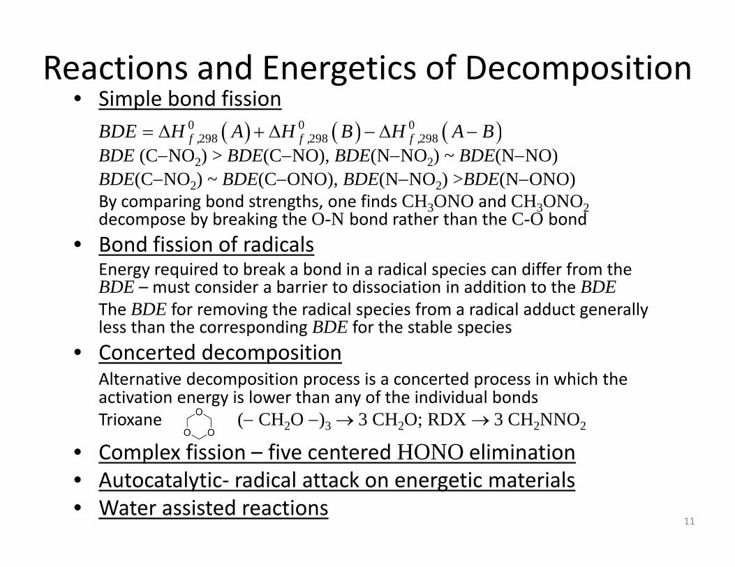
Reactions and Energetics of Decomposition • Simple bond fissionSimple bond fission
BDE (C−NO2) > BDE(C−NO), BDE(N−NO2) ~ BDE(N−NO)BDE(C NO ) BDE(C ONO) BDE(N NO ) >BDE(N ONO)
( ) ( ) ( )0 0 0298 298 298f , f , f ,BDE H A H B H A B= Δ + Δ − Δ −
BDE(C−NO2) ~ BDE(C−ONO), BDE(N−NO2) >BDE(N−ONO)By comparing bond strengths, one finds CH3ONO and CH3ONO2decompose by breaking the O-N bond rather than the C-O bond
• Bond fission of radicalsBond fission of radicalsEnergy required to break a bond in a radical species can differ from the BDE – must consider a barrier to dissociation in addition to the BDEThe BDE for removing the radical species from a radical adduct generally less than the corresponding BDE for the stable species
• Concerted decompositionAlternative decomposition process is a concerted process in which the
l h f h d d l b dactivation energy is lower than any of the individual bondsTrioxane (− CH2O −)3 → 3 CH2O; RDX → 3 CH2NNO2
• Complex fission – five centered HONO eliminationp• Autocatalytic‐ radical attack on energetic materials• Water assisted reactions
11

Bond Dissociation Energies for Various Nitro, Nitroso, Nitrite, and Nitrate Species in kcal/mol
Nitroso CompoundsH−NO 50.3CH3−NO 37 6
Nitro CompoundsH−NO2 73.4CH3−NO2 58 9
Nitrite CompoundsH−ONO 78.3CH3−ONO 57 3CH3 NO 37.6
NH2−NO 49.4HO−NO 50.2CH3O NO 43 5
CH3 NO2 58.9NH2−NO2 51.4HO−NO2 46.8CH3O NO2 39 9
CH3 ONO 57.3NH2−ONO 32.9HO−ONO 17.1CH3NH ONO 29 3CH3O−NO 43.5
CH2H−NO 22.1CH3NH−NO 48.7CH2CH NO 51 0
CH3O−NO2 39.9CH2H−NO2 37.1CH3NH−NO2 50.6CH2CH NO2 70 2
CH3NH−ONO 29.3(CH3)2N−ONO 28.1CH2N−ONO 22.1CH2CH ONO 68 5CH2CH−NO 51.0
C2H5‐NO 38.5NH2CHCH−NO 60.6
CH2CH−NO2 70.2C2H5‐NO2 60.8NH2CHCH−NO2 78.2
CH2CH−ONO 68.5C2H5‐ONO 59.3CHO−ONO 60.0
CHO−NO 29.2NH2O−NO 17.1HOO−NO 25.5
CHO−NO2 49.8(CH3)2N−NO2 45.9NH2CHCH−NO2 78.2
Nitrate CompoundsH−ONO2 105.0
CH3NHO−NO 12.1CH2CHO−NO 15.5
CH3−ONO2 83.7
From Melius, 1989 12
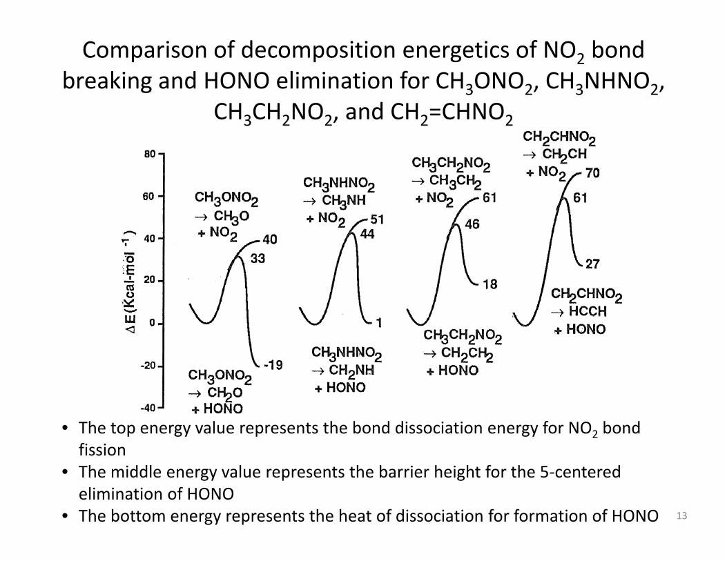
Comparison of decomposition energetics of NO2 bond breaking and HONO elimination for CH3ONO2, CH3NHNO2,
CH CH NO d CH CHNOCH3CH2NO2, and CH2=CHNO2
• The top energy value represents the bond dissociation energy for NO2 bond fission
• The middle energy value represents the barrier height for the 5‐centered elimination of HONO
• The bottom energy represents the heat of dissociation for formation of HONO 13

Reaction of CH3NHNO2 + H
14From Melius, 1989

Reaction diagrams for the water catalyzed concerted reaction for the conversion of nitramine, NH2NO2, to N2O+H2O through
the intermediate aci form, HNN(O)OH
• In the first concerted mechanism, the H from the nitramine shifts to the water molecule while the H on the water shifts to the O of the nitramine, forming the acimoleculeI th d t th i l l i t d t N O d H O b i• In the second step, the acimolecule is converted to N2O and H2O by again having the H bonded to the N shifting to the water molecule while the H on the water molecule is shifted to the OH group of the acimolecule
15From Melius, 1989

Necessary and SufficientExperiments Model / Theoryc
Gas‐Phase Experiments and Model Development
Experiments
Coupled Combustion ChemistryTransport & Heat Release
1‐D Gas Phase Model
Transport and Heat Release
Simulation & Validation
yac
rosc
opic
Diffusion and Premixed Flames
Combustion Chemistry
Transport and Heat ReleaseAdded to Elementary Chemistry
0‐D Gas Phase ModelSimulation & Validation
ma
Shock Tubes Flow ReactorsStatic Reactors
Simulation & Validation
Complex Chemistry Only
Semi‐Empirical Theory
Isolated Species and Reactions
Rate Constant Measurements
Rate Constant EstimatesCritical Data AnalysisThermochemistry
pic
Product Detection Transport Theory
Electronic StructureReaction RateTransportm
icro
scop
Multiple and ComplementaryDiagnostics
Sensitivity Analysis16
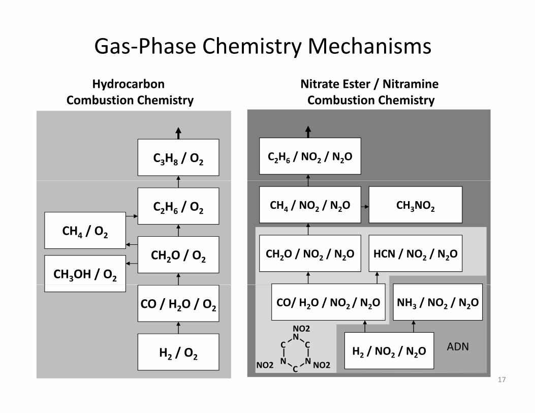
Gas‐Phase Chemistry MechanismsHydrocarbon
Combustion ChemistryNitrate Ester / NitramineCombustion Chemistry
C3H8 / O2 C2H6 / NO2 / N2O
C2H6 / O2
CH4 / O2
CH4 / NO2 / N2O CH3NO2
CH2O / O2
CH4 / O2
CH2O / NO2 / N2O HCN / NO2 / N2O
CH3OH / O2
CO / H2O / O2 CO/ H2O / NO2 / N2O NH3 / NO2 / N2O
NO2N
H2 / O2H2 / NO2 / N2O
NO2NO2
C C
C
N
NN
ADN
17

Gas‐Phase Submodel Development
Flow reactor studies of a CH4/N2O/N2 mixture reacting at 3 3 atm and 1153 Kat 3.3 atm and 1153 K
Flow reactor studies of N2O decomposition at 6 atm and 1123 K
18
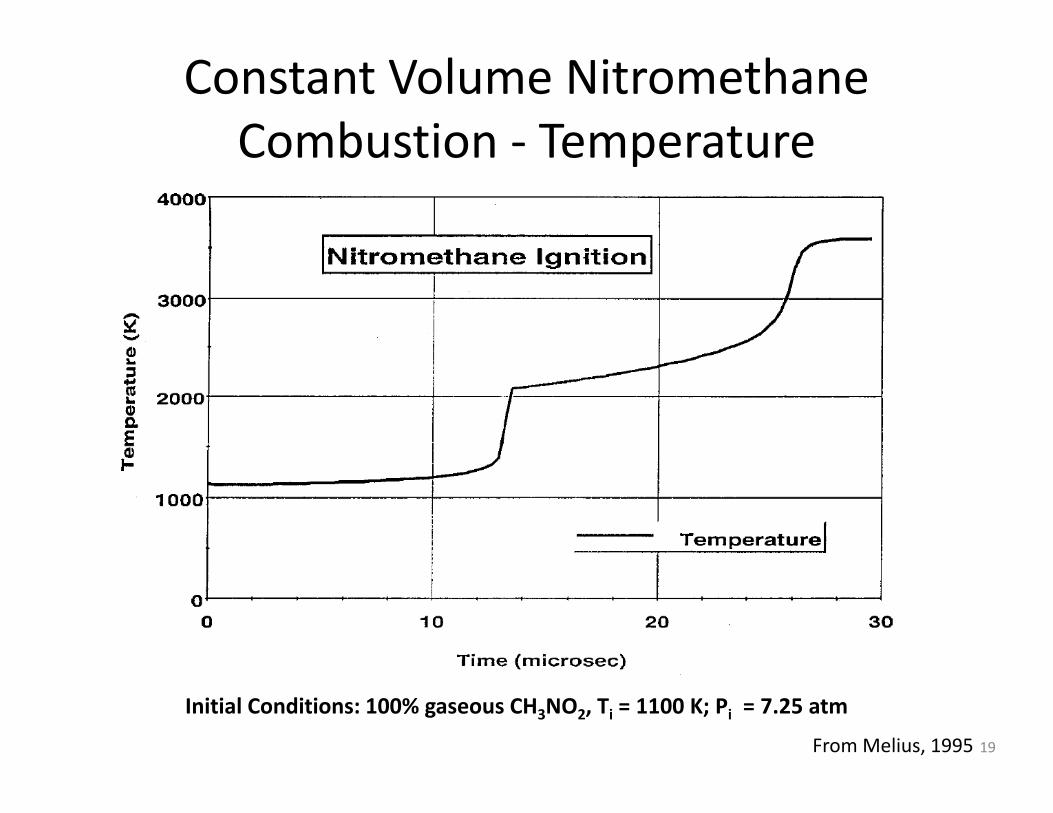
Constant Volume NitromethaneCombustion ‐ TemperatureCombustion Temperature
From Melius, 1995
Initial Conditions: 100% gaseous CH3NO2, Ti = 1100 K; Pi = 7.25 atm
19

Constant Volume NitromethaneCombustion ‐ SpeciesCombustion Species
CH3NO2CH3NO2
NO
CO
H2H2OCH2O NO
N2CH4 HCNH2OCH2O
From Melius, 1995Initial Conditions: 100% gaseous CH3NO2, Ti = 1100 K; Pi = 7.25 atm
20

Nitromethane First Stage Chemistry
From Melius, 1995 21
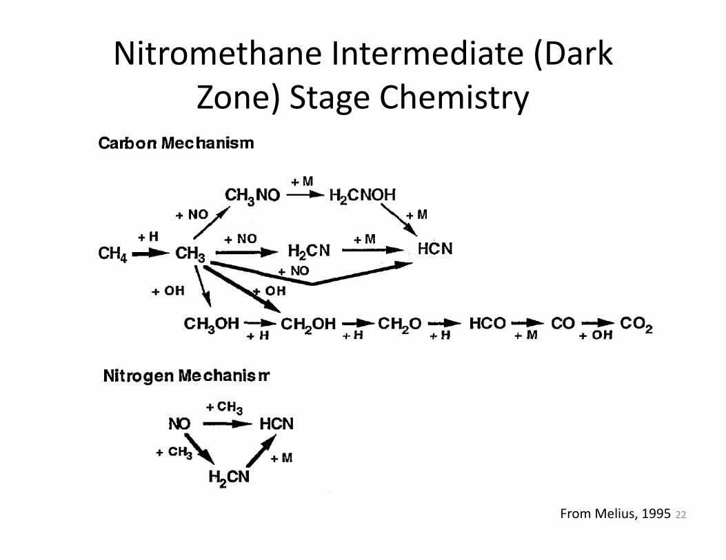
Nitromethane Intermediate (Dark Zone) Stage ChemistryZone) Stage Chemistry
From Melius, 1995 22

Nitromethane Second Stage Chemistry
From Melius, 1995 23

Flame Structure of a Double‐Base Propellant
I. Preheat Zone: heating of propellant occurs without chemical reaction
Flame zoneDark zoneSolid phase reaction zone
II. Solid‐phase reaction zone: Thermal decomposition begins by CO−NO2 bond breaking
III Fi Z NO d ld h dT
Tg
Fizz zone
III. Fizz Zone: NO2 and aldehydesreact with other gaseous species to produce NO, CO, H2, and CO2Ts
Td
I II III IV V
DB propellantTu
2IV. Dark (induction) zone: slow oxidation reaction of the products formed from the fizz zone The dark zone isT0
TsDB propellant
zone. The dark zone is considered isothermal with nearly negligible thermal and mass diffusion.
Burning surface
RONONO2 NO, H2 N2, CO
V. Luminous flame zone: Final products are formed and remainder of heat released
24
RONO22
R’CHO2
CO, CO2
2CO2, H2O
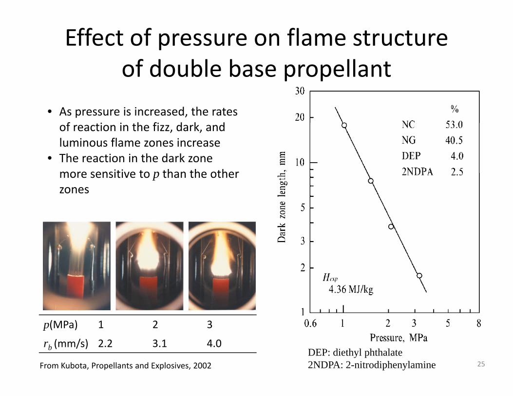
Effect of pressure on flame structure of double base propellantof double base propellant
• As pressure is increased, the rates f i i h fi d k dof reaction in the fizz, dark, and
luminous flame zones increase• The reaction in the dark zone more sensitive to p than the othermore sensitive to p than the other zones
(MPa) 1 2 3p(MPa) 1 2 3
rb (mm/s) 2.2 3.1 4.0DEP: diethyl phthalate2NDPA: 2-nitrodiphenylamine 25From Kubota, Propellants and Explosives, 2002

Flame Structure of Double Based llPropellants
• Condensed phase mechanisms are often neglected due to the lack of their understanding
• In addition to possible vaporization, initial condensed phase decomposition is assumed to occur at the surface
• A pyrolysis law relates the surface temperature to the rate of reaction, e.g., Zenin (1980) from empirical studies developed the following pyrolysis law for DB propellants
⎛ ⎞
• Various types of thermolysis experiments where the
( ) ( )2 3 5000g/m 1 8 10 b p
s
m s . exp rT K
ρ⎛ ⎞
′′ − = × − =⎜ ⎟⎜ ⎟⎝ ⎠
• Various types of thermolysis experiments where the surface is heated in a low temperature (and often low pressure) gas environment are used to measure the species composition evolving from the surfacecomposition evolving from the surface
26
Flame Structure of Double Based ll ’dPropellants‐cont’d
• The condensed phase of very few simple ingredients, such as RDX, and a few simple binary mixtures, have been studied
• Detailed gas‐phase processes, including complexDetailed gas phase processes, including complex elementary reaction mechanisms, heat transfer, and multicomponent diffusion have been used in one and two dimensions to study the flame structure andtwo dimensions to study the flame structure and burning rate behavior.
• One example is the work of Miller and Anderson (2000) who have developed detailed models to study flamewho have developed detailed models to study flame structure and predict burning rates of multi‐ingredient DB propellants
27
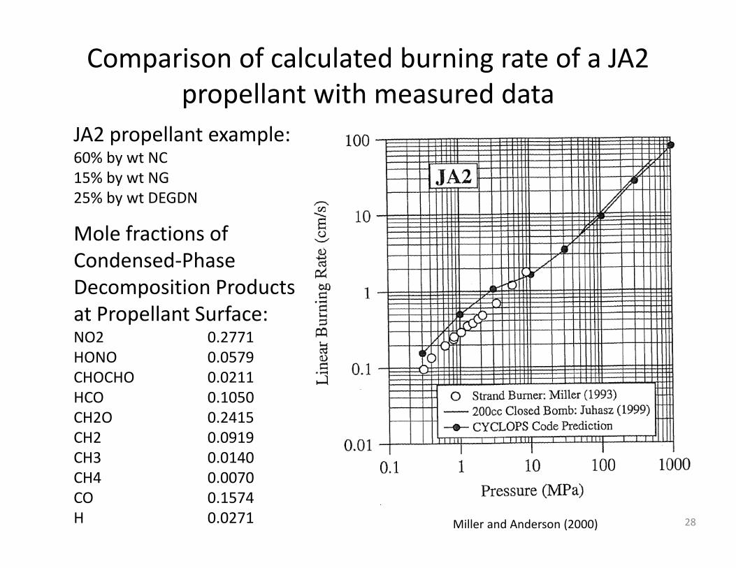
Comparison of calculated burning rate of a JA2 propellant with measured datap p
JA2 propellant example:60% by wt NC15% by wt NG15% by wt NG25% by wt DEGDN
Mole fractions of Condensed‐Phase Decomposition Products at Propellant Surface:at Propellant Surface:NO2 0.2771HONO 0.0579CHOCHO 0.0211HCO 0.1050CH2O 0.2415CH2 0.0919CH3 0.0140CH4 0.0070CO 0.1574H 0.0271 28Miller and Anderson (2000)

Comparison of measured and calculated temperature and NO mole fraction profiles for a JA2 propellant at T = 294 Kmole fraction profiles for a JA2 propellant at Ti = 294 K
29Miller and Anderson (2000)
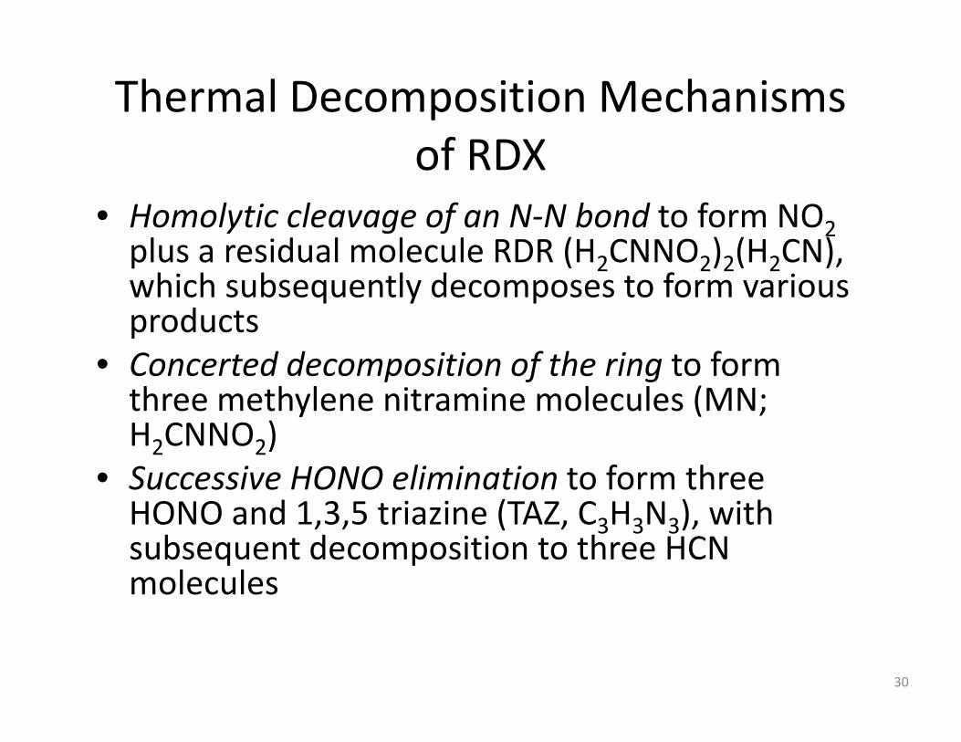
Thermal Decomposition Mechanisms fof RDX
• Homolytic cleavage of an N‐N bond to form NO2y g f 2plus a residual molecule RDR (H2CNNO2)2(H2CN), which subsequently decomposes to form various productsproducts
• Concerted decomposition of the ring to form three methylene nitramine molecules (MN; H2CNNO2)
• Successive HONO elimination to form three HONO and 1 3 5 triazine (TAZ C H N ) withHONO and 1,3,5 triazine (TAZ, C3H3N3), with subsequent decomposition to three HCN molecules
30
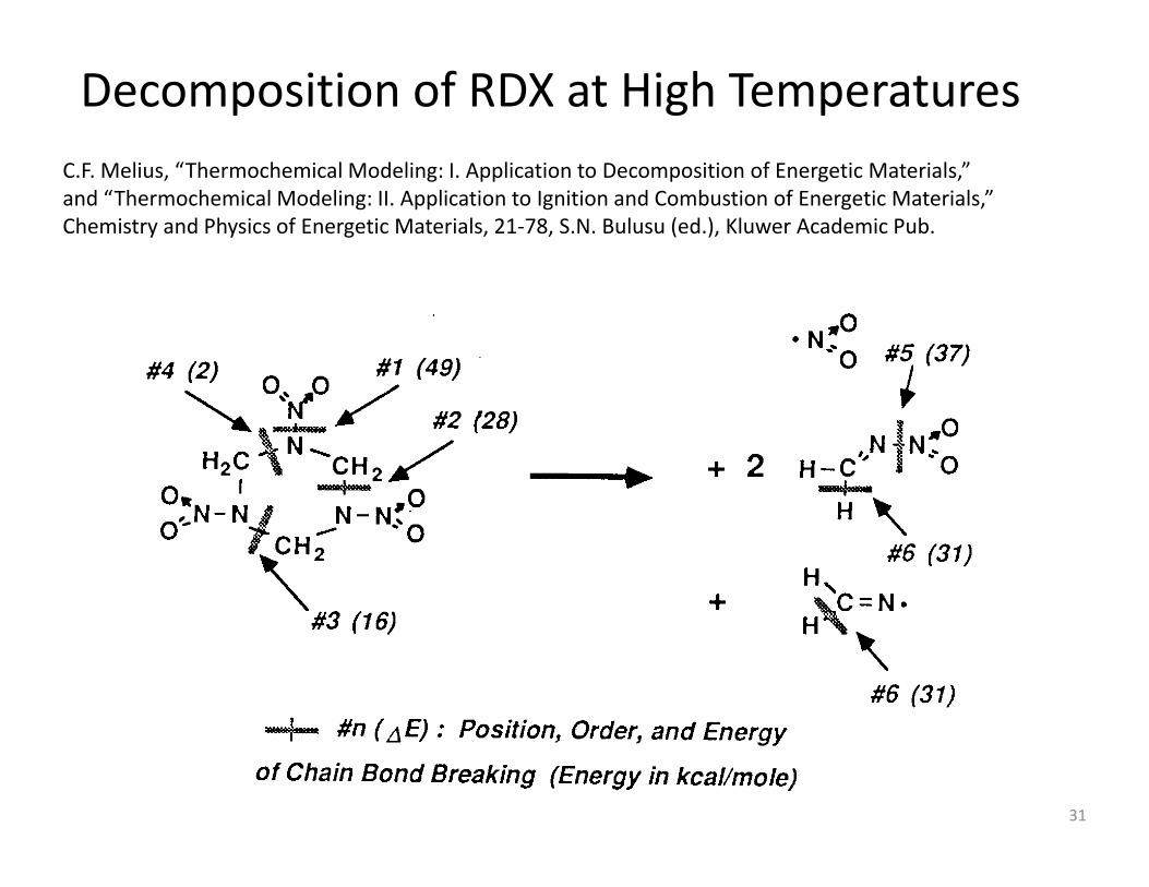
Decomposition of RDX at High TemperaturesC F M li “Th h i l M d li I A li ti t D iti f E ti M t i l ”C.F. Melius, “Thermochemical Modeling: I. Application to Decomposition of Energetic Materials,”and “Thermochemical Modeling: II. Application to Ignition and Combustion of Energetic Materials,”Chemistry and Physics of Energetic Materials, 21‐78, S.N. Bulusu (ed.), Kluwer Academic Pub.
31
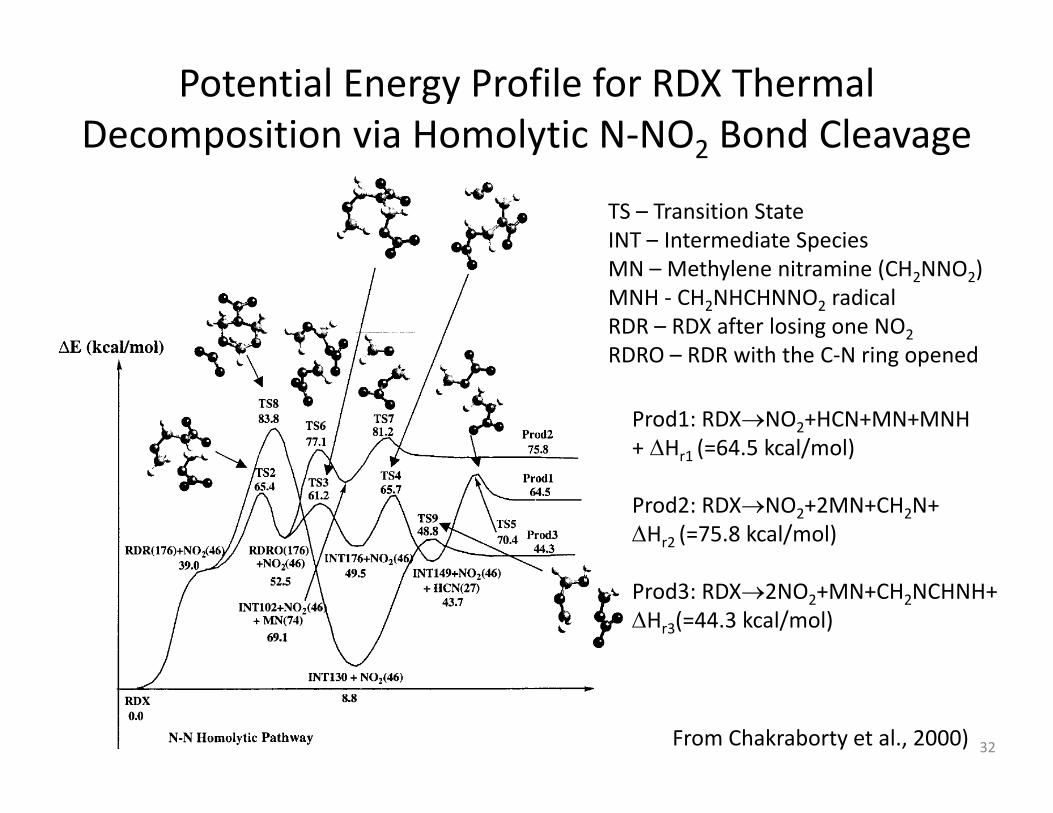
Potential Energy Profile for RDX Thermal Decomposition via Homolytic N‐NO2 Bond Cleavagep y 2 g
TS – Transition StateINT – Intermediate SpeciesMN – Methylene nitramine (CH2NNO2)MNH ‐ CH2NHCHNNO2 radicalRDR – RDX after losing one NO2RDRO – RDR with the C N ring openedRDRO – RDR with the C‐N ring opened
Prod1: RDX→NO2+HCN+MN+MNH+ ΔHr1 (=64.5 kcal/mol)r1 ( / )
Prod2: RDX→NO2+2MN+CH2N+ΔHr2 (=75.8 kcal/mol)
Prod3: RDX→2NO2+MN+CH2NCHNH+ΔHr3(=44.3 kcal/mol)
From Chakraborty et al., 2000) 32
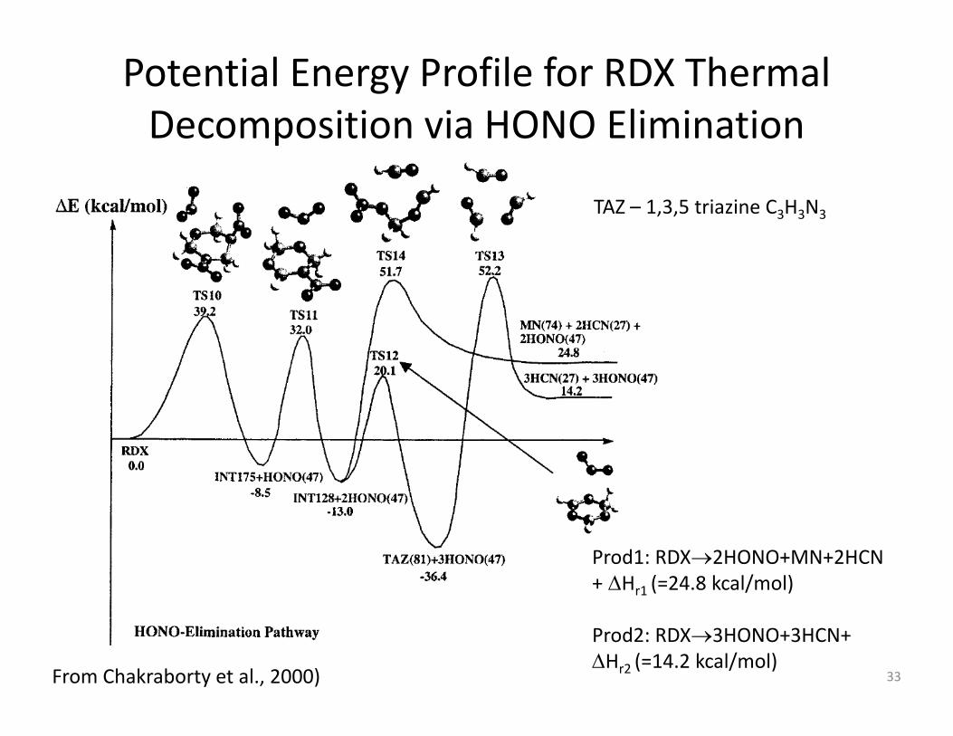
Potential Energy Profile for RDX Thermal Decomposition via HONO EliminationDecomposition via HONO Elimination
TAZ – 1,3,5 triazine C3H3N3
Prod1: RDX→2HONO+MN+2HCN+ ΔHr1 (=24.8 kcal/mol)
From Chakraborty et al., 2000)
Prod2: RDX→3HONO+3HCN+ΔHr2 (=14.2 kcal/mol)
33

Condensed Phase Chemical Kinetic Studies
Experiment Heating Rate
Si lt th i t i 10 2 K/Simultaneous thermogravimetric 10‐2 K/smodulated beam mass spectroscopy (STMBS)R. Behrens ‐ Sandia
T‐jump/FTIR 103 K/sT jump/FTIR 10 K/sT. Brill ‐ U DelawareConfined Rapid ThermolysisS Th ll P St tS. Thynell – Penn State
Pulsed laser heating / 107 K/sthermal quenchC. Wight ‐ U Utah
34
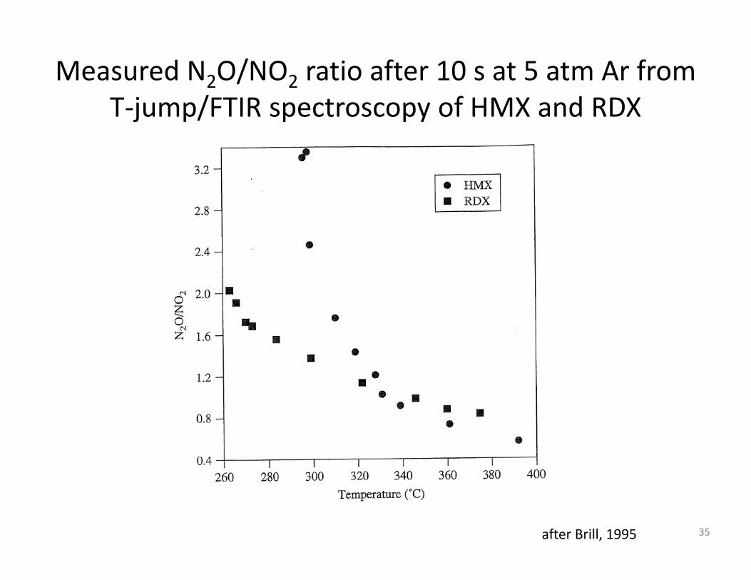
Measured N2O/NO2 ratio after 10 s at 5 atm Ar from T jump/FTIR spectroscopy of HMX and RDXT‐jump/FTIR spectroscopy of HMX and RDX
35after Brill, 1995

Condensed‐Phase Reaction MechanismsT.B. Brill, J. Prop. Power, 11, 4, 1995; S. Thynell, P. Gongwer, and T.Brill,J. Prop. Power, 12, 933, 1996
HMX(RDX)
4(3) (CH2O + N2O) (‐29 kcal/mol) 1
4(3) (HCN HONO) (28 k l/ l) 24(3) (HCN + HONO) (28 kcal/mol) 2
CH2O + NO2 CO + NO + H2O (‐44 kcal/mol) 3
RDX Thermal Decomposition Rate ParametersReaction 1 2 3A 6x10¹³ s‐1 16x1016 s‐1 802x T2.77 cm3/mol‐sE 36 kcal/mol 45 kcal/mol 25.73 kcal/mol
E.S. Kim and S.T. Thynell, “Condensed Phase Rates of RDX from Confined RapidThermolysis/FTIR Spectroscopy,” AIAA 98‐3828, 34th AIAA PropulsionConference and Exhibit, Cleveland, OH, July 13‐15, 1998
Global 10 step condensed phase reaction mechanism obtainedGlobal 10 step condensed phase reaction mechanism obtained by inverse‐based iterative fitting
36

Thermal Decomposition of Liquid Phase RDX
• Elementary reactions identified using abinitio quantum chemistry methods including density functional theory
• Liquid phase reactionsLiquid phase reactions are simulated using the conductor‐like polarizable continuum f l hfor solvation with water as solvent
P1: HONO elimination
P2: N‐NO2 homolysis
Patidar and Thynell, Combustion & Flame, Vol. 178, April 2017 37
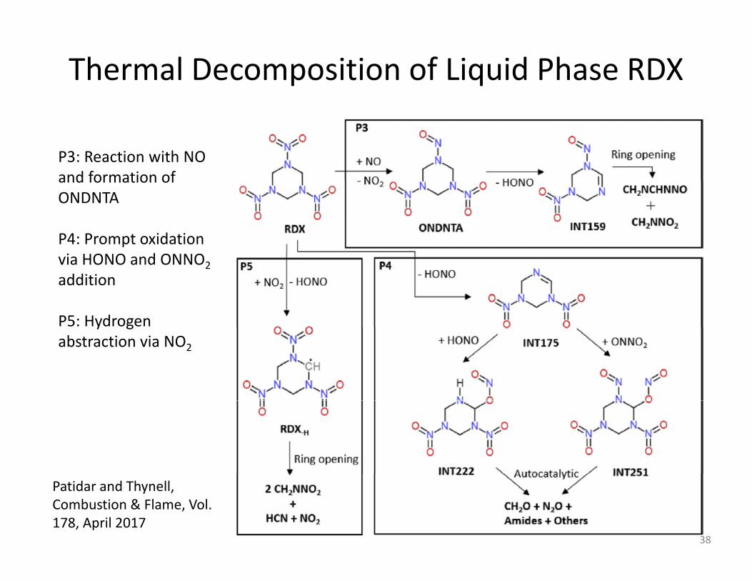
Thermal Decomposition of Liquid Phase RDX
P3: Reaction with NO and formation ofand formation of ONDNTA
P4: Prompt oxidation i HONO d ONNOvia HONO and ONNO2addition
P5: Hydrogen y gabstraction via NO2
Patidar and Thynell, Combustion & Flame, Vol. 178, April 2017
38

Thermal Decomposition of Liquid Phase RDX/• Confined rapid thermolysis/FTIR spectroscopy, where 0.5mg of RDX
is heated at 2000K/s to 548 K at 1 atm• HONO elimination is more significant than N‐NO2 homolyticcleavage in liquid phase
• HONO elimination is followed by ring opening instead of successive HONO elimination
experiment model
From Patidar and Thynell, Combustion & Flame, Vol. 178, April 2017, pp. 7–20; Khichar, Patidar and Thynell, 10th National Combustion Meeting, April 23‐26, 2017; results on HMX decomposition is also presented at the 10th National Combustion Meeting. 39

Temperature Profiles in Various Flame Zones and Condensed‐Phase Regions of Nitramine
Monopropellant
Formation of N2O and CH2OFavored at lower temperatureFavored at lower temperature
RDX 40

Modeling of RDX Combustion
• Numerical models have included detailedNumerical models have included detailed chemical kinetics and transport phenomena in the gas‐phase and thermal decomposition andthe gas phase and thermal decomposition and subsequent reactions in the condensed phase
• Formation of gas bubbles in the subsurface• Formation of gas bubbles in the subsurface layer to molecular degradation and evaporation has also been includedevaporation has also been included
• Model for RDX Combustion by Liau and Yang
41
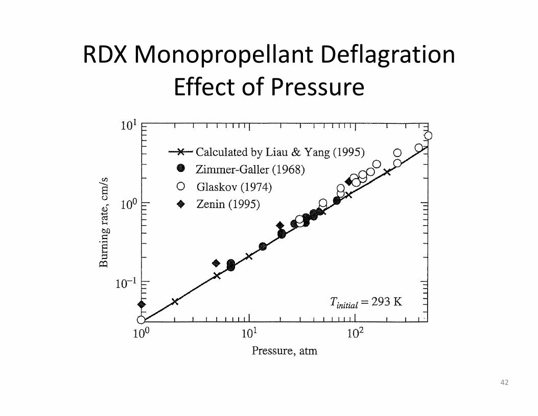
RDX Monopropellant Deflagration ff fEffect of Pressure
42

Calculated temperature Profiles of Self‐Sustained RDX Combustion at Various PressuresSustained RDX Combustion at Various Pressures
43

Comparisons of Calculated and Measured Major Species Concentrations at P=0.5 atm
44
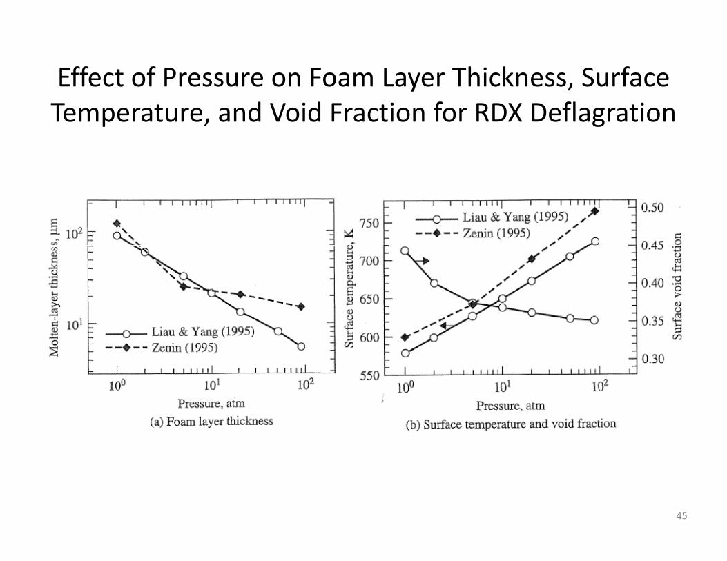
Effect of Pressure on Foam Layer Thickness, Surface T d V id F i f RDX D fl iTemperature, and Void Fraction for RDX Deflagration
45

Temperature Sensitivity Calculations
0.005
0.006
ty (1
/K)
RDX, Model
0.003
0.004re
Sen
sitiv
it
HMX, Data
HMX, Model
RDX, Data
,
AP
HMX
0.001
0.002
Tem
pera
tu
AP, Data
AP, Model
RDX0
0 25 50 75 100
Pressure (atm)
RDX
• HMX σp increases dramatically at low pressure• RDX σp increases slightly at low pressure• AP σp ~constantAP σp constant• Washburn HMX condensed phase model includes Marangoni
surface tension effectWashburn & Beckstead 2006 46
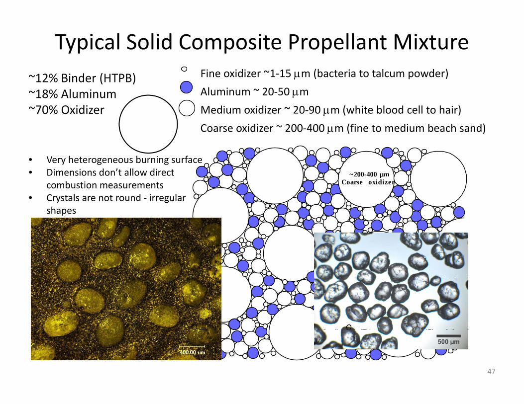
Typical Solid Composite Propellant Mixture12% Bi d (HTPB) Fine oxidizer ~1‐15 μm (bacteria to talcum powder)~12% Binder (HTPB)~18% Aluminum~70% Oxidizer
Fine oxidizer 1 15 μm (bacteria to talcum powder)
Aluminum ~ 20‐50 μm
Medium oxidizer ~ 20‐90 μm (white blood cell to hair)
C idi ~ 200 400 (fi t di b h d)
~200-400 µm
Coarse oxidizer ~ 200‐400 μm (fine to medium beach sand)
• Very heterogeneous burning surface• Dimensions don’t allow direct 00 00 µ
Coarse oxidizercombustion measurements• Crystals are not round ‐ irregular
shapes
47

Hierarchical Approach Applied
Start with the simplest systems and work up, with validations at each stepvalidations at each step• 1‐D Monopropellant: Single ingredient
−Gas phase and condensed phase chemistry developmentGas p ase a d co de sed p ase c e st y de e op e t−Surface regression models
• 1‐D Composite propellant: Add chemical complexity without ti l l itspatial complexity
−Chemistry interaction• 1‐D Counterflow: Add diffusion flame, but remain 1‐D,
−Chemistry with fluid dynamics−Oxidizer with binder decomposition product chemistry
48
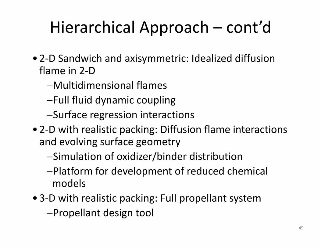
Hierarchical Approach – cont’d
•2‐D Sandwich and axisymmetric: Idealized diffusion flame in 2‐D−Multidimensional flames−Full fluid dynamic coupling−Surface regression interactions
•2‐D with realistic packing: Diffusion flame interactions d l i f tand evolving surface geometry−Simulation of oxidizer/binder distributionPlatform for development of reduced chemical−Platform for development of reduced chemical models
•3‐D with realistic packing: Full propellant systemp g p p y−Propellant design tool
49
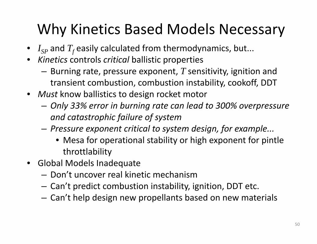
Why Kinetics Based Models NecessaryI d T il l l d f h d i b• ISP and Tf easily calculated from thermodynamics, but...
• Kinetics controls critical ballistic properties– Burning rate, pressure exponent, T sensitivity, ignition and transient combustion, combustion instability, cookoff, DDT
• Must know ballistics to design rocket motor– Only 33% error in burning rate can lead to 300% overpressureOnly 33% error in burning rate can lead to 300% overpressure and catastrophic failure of system
– Pressure exponent critical to system design, for example...M f i l bili hi h f i l• Mesa for operational stability or high exponent for pintlethrottlability
• Global Models Inadequate– Don’t uncover real kinetic mechanism– Can’t predict combustion instability, ignition, DDT etc.– Can’t help design new propellants based on new materialsCan t help design new propellants based on new materials
50
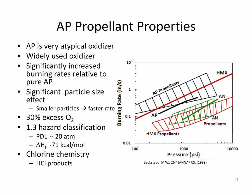
AP Propellant Properties• AP is very atypical oxidizer• Widely used oxidizer• Significantly increased
burning rates relative to pure APp
• Significant particle size effect– Smaller particles faster rateSmaller particles faster rate
• 30% excess O2• 1.3 hazard classification
PDL 20– PDL ~ 20 atm– ΔHf ‐71 kcal/mol
• Chlorine chemistry– HCl products Beckstead, M.W., 26th JANNAF CS, (1989)
51
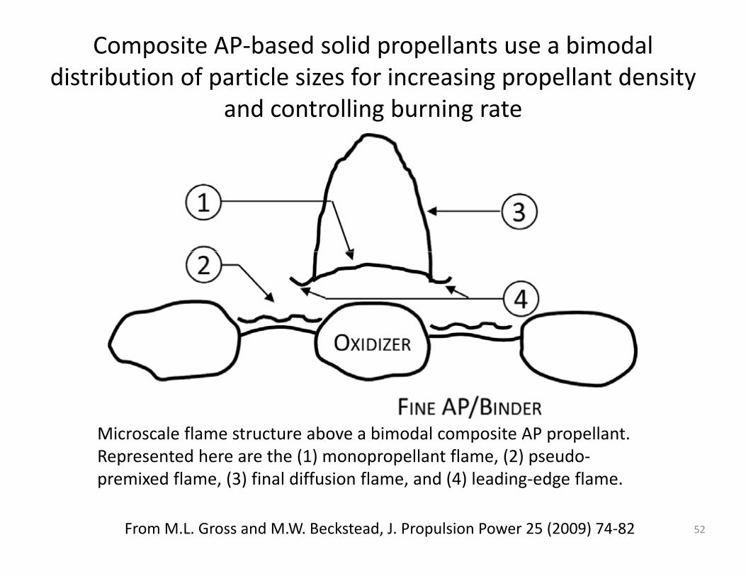
Composite AP‐based solid propellants use a bimodal distribution of particle sizes for increasing propellant density
and controlling burning rateand controlling burning rate
Microscale flame structure above a bimodal composite AP propellant. Represented here are the (1) monopropellant flame, (2) pseudo‐premixed flame, (3) final diffusion flame, and (4) leading‐edge flame.
From M.L. Gross and M.W. Beckstead, J. Propulsion Power 25 (2009) 74‐82 52

AP Decomposition Kinetics and Monopropellant DeflagrationMonopropellant Deflagration
• Chen and McQuaid (2014 JANNAF CS Meeting) have developed the mostMeeting) have developed the most recent gas‐phase mechanism consisting of 788 reaction rate expressions and 105 species
• The condensed phase mechanism remains uncertain. Most recently, Zhu and Lin ( J. Phys. Chem. C 112 (2008) 14481) proposed a dissociative sublimation mechanism of crystal NH4ClO4(c) that involves a
( )NH3…HClO4(g) complex
NH4ClO4(c)↔NH4ClO4(s) ↔NH3…HClO4(g) ↔NH3(g)+HClO4(g)
where NH4ClO4(s) corresponds to a relaxed surface of the crystal Chen and McQuaid (2014 JANNAF CS Meeting
53

Propellant Surface and Sub‐Surface• Condensed phase and interface/surface phenomena is the least
understood– The surface reaction zone is very thin, multiphase, and has a
steep temperature gradient• Several studies used cinephotomicrography to observe burning
surface, then sample was quenched and examined using scanning electron microscopy
• Other studies used fast thermolysis and FTIR to measure decomposition products
• Typically microthermocouples are embedded within propellant sample at various distances fromsample at various distances from the surface to measure thermal response of propellantN d i f ti d d h ti AP h h
R. Derr and T. Boggs, Combustion Science and Technology, 1:5, 369‐384, 1970.
• Need information on condensed phase reactions, AP phase changes and binder decomposition before reaching the burning surface
54
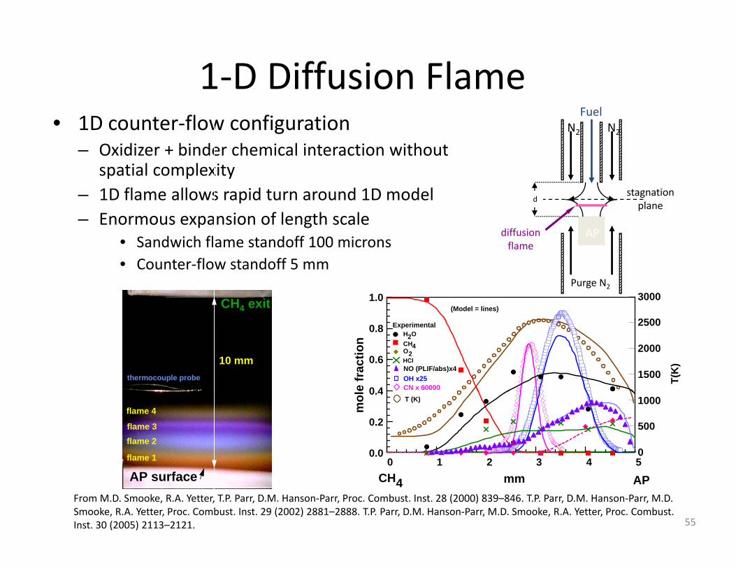
1‐D Diffusion Flame• 1D counter‐flow configuration
– Oxidizer + binder chemical interaction without spatial complexity
FuelN2 N2
p p y– 1D flame allows rapid turn around 1D model– Enormous expansion of length scale
• Sandwich flame standoff 100 micronsdiffusion flame
AP
dstagnation plane
• Counter‐flow standoff 5 mmPurge N2
flame
2500
3000(Model = lines)
1.0CH4 exit
H2OCH4
NO (PLIF/abs)x4
T(K
)
1500
2000
2500
HClO2
Experimental
OH x25CN x 600000 4
0.6
0.8
e fr
actio
n10 mm
thermocouple probe
0
500
1000T (K)
0 1 2 3 4 50.0
0.2
0.4
mol
flame 1
flame 2flame 3
flame 4
APCH4 mm0 1 2 3 4 5
AP surfaceFrom M.D. Smooke, R.A. Yetter, T.P. Parr, D.M. Hanson‐Parr, Proc. Combust. Inst. 28 (2000) 839–846. T.P. Parr, D.M. Hanson‐Parr, M.D. Smooke, R.A. Yetter, Proc. Combust. Inst. 29 (2002) 2881–2888. T.P. Parr, D.M. Hanson‐Parr, M.D. Smooke, R.A. Yetter, Proc. Combust. Inst. 30 (2005) 2113–2121. 55

2D Gaseous Fuel AP Diffusion Flames
• With kinetics finalized via 1D counter‐flow flames, extended model and experiment to 2D geometrygeometry
• Started with simplicity of the same gaseous fuel (methane or ethylene) as 1D work
AP
Diffusion Flame
• Axisymmetric (experiment and modeling)– Small fuel hole in center of big
domain of AP Drilled hole in AP pellet
AP flame
– 990 μm down to 60 μm– O‐ring seal to AP cylinder – CH4 fed below at desired rate– CH exit velocity was 9 75
AP AP Pellet
CH4 exit velocity was 9.75m/sec peak, parabolic flow
CH4
330 μm hole330 μm hole330 μm hole330 μm hole
From M.D. Smooke, R.A. Yetter, T.P. Parr, D.M. Hanson‐Parr, Proc. Combust. Inst. 28 (2000) 839–846. T.P. Parr, D.M. Hanson‐Parr, M.D. Smooke, R.A. Yetter, Proc. Combust. Inst. 29 (2002) 2881–2888. T.P. Parr, D.M. Hanson‐Parr, M.D. Smooke, R.A. Yetter, Proc. Combust. Inst. 30 (2005) 2113–2121. 56
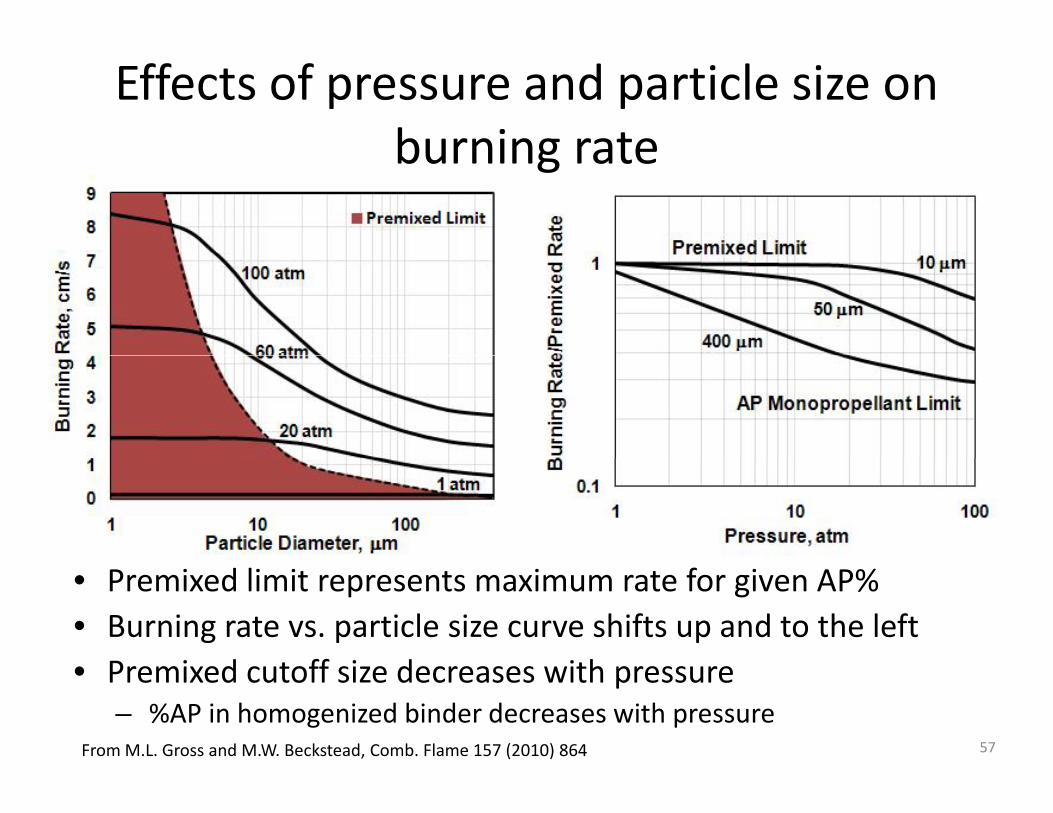
Effects of pressure and particle size on burning rateburning rate
• Premixed limit represents maximum rate for given AP%• Burning rate vs. particle size curve shifts up and to the leftP i d t ff i d ith• Premixed cutoff size decreases with pressure– %AP in homogenized binder decreases with pressure
From M.L. Gross and M.W. Beckstead, Comb. Flame 157 (2010) 864 57
3D Modeling of Heterogeneous llPropellants
• Over the past two decades, parallel computing p , p p ghas become a staple of engineering calculations, with multidimensional simulations of heterogeneous propellants following this trendheterogeneous propellants following this trend
• Jackson and Buckmaster carried out first three dimensional simulation of solid propellant in 2000
• Random packing algorithms are used to generate the microstructure of a heterogeneous propellantthe microstructure of a heterogeneous propellant and an unsteady solid gas numerical code for the combustion problem
58
Random Packing Algorithm for Generating Realistic MicrostructuresGenerating Realistic Microstructures
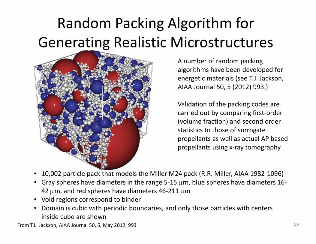
A number of random packing algorithms have been developed for
i i l ( kenergetic materials (see T.J. Jackson, AIAA Journal 50, 5 (2012) 993.)
Validation of the packing codes are p gcarried out by comparing first‐order (volume fraction) and second order statistics to those of surrogate propellants as ell as act al AP basedpropellants as well as actual AP based propellants using x‐ray tomography
• 10,002 particle pack that models the Miller M24 pack (R.R. Miller, AIAA 1982‐1096)• Gray spheres have diameters in the range 5‐15 μm, blue spheres have diameters 16‐
42 μm, and red spheres have diameters 46‐211 μm• Void regions correspond to binder• Void regions correspond to binder• Domain is cubic with periodic boundaries, and only those particles with centers
inside cube are shownFrom T.L. Jackson, AIAA Journal 50, 5, May 2012, 993 59

Chemistry for Heterogeneous Propellants• The inclusion of elementary kinetics (hundreds of species) for the
gas‐phase is well beyond the scope of today’s most powerful supercomputers; and the condensed phase chemistry remains generally poorly understoodgenerally poorly understood
• Simple global kinetic schemes are adopted, and the challenge is identification of the appropriate parameters for the kinetics
• In the context of AP/HTPB propellants a three step model familiarIn the context of AP/HTPB propellants, a three step model, familiar from the BDP model is used, characterized by an AP diffusion decomposition flame, primary diffusion flame, and secondary diffusion flame
1 (AP d t )RAP P1
2
3
(AP products)Rd
Rpdf
Rd df
AP PAP HTPB PHTPB P P
⎯⎯→+ ⎯⎯→
+ ⎯⎯→
• Based on the 2D single particle AP/HTPB modeling results, the mechanism was modified to a 4‐step reaction that included a premixed binder flame above the homogenized AP/HTPB mixture
d sdfHTPB P P+ →
premixed binder flame above the homogenized AP/HTPB mixture
From T.L. Jackson, AIAA Journal 50, 5, May 2012, 993Gross et al. Comb. Flame 160 (2013) 982 60

Premixed Binder• Assume fine AP and HTPB form homogeneous mixture
– Experimentally supported– Experimentally supported
– AP/HTPB react in premixed, laminar reaction zone
– Limits numerical resolution (Shorter runtime)( )
Full pack Homogenized pack
61
AP/HTPB composite propellant burning as a function of pressureburning as a function of pressure
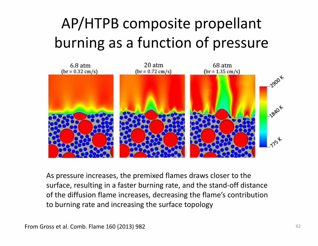
As pressure increases, the premixed flames draws closer to the surface, resulting in a faster burning rate, and the stand‐off distance of the diffusion flame increases, decreasing the flame’s contribution to burning rate and increasing the surface topology
From Gross et al. Comb. Flame 160 (2013) 982 62
Surface topography and temperature level surfaces for a sample 3D propellant burning at 20 atmp p p g
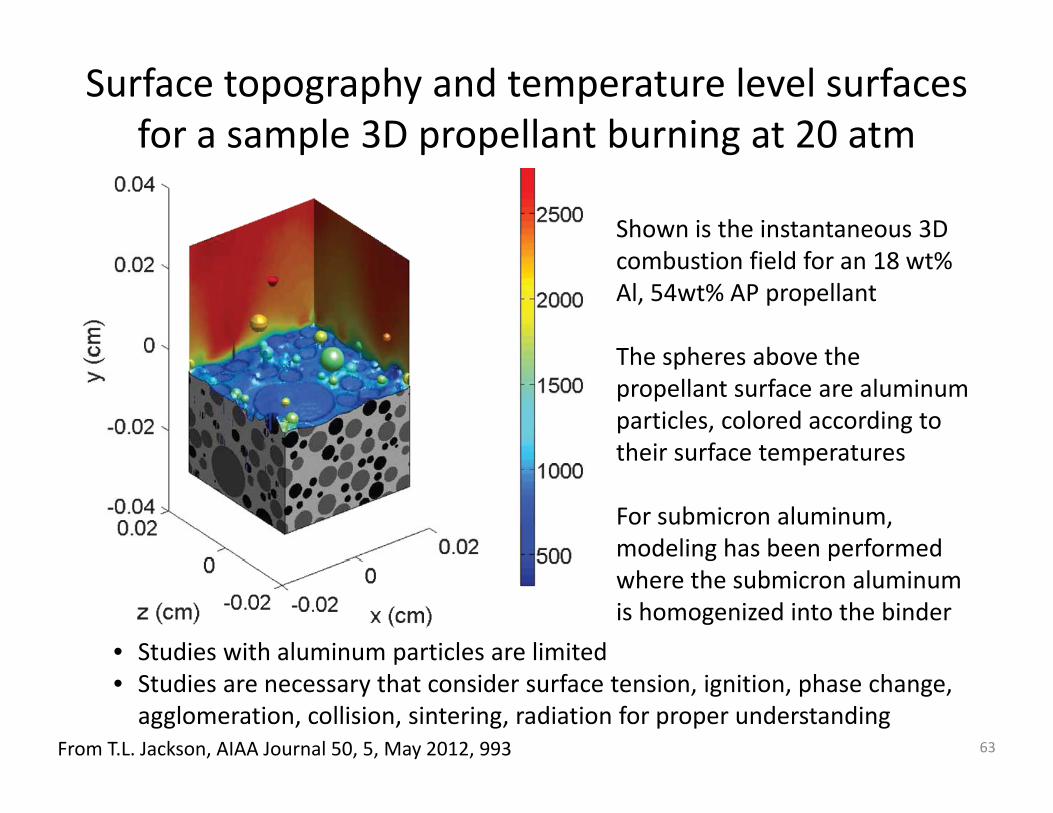
Shown is the instantaneous 3D b i fi ld f 18 %combustion field for an 18 wt%
Al, 54wt% AP propellant
The spheres above theThe spheres above the propellant surface are aluminum particles, colored according to their surface temperaturestheir surface temperatures
For submicron aluminum, modeling has been performed g pwhere the submicron aluminum is homogenized into the binder
• Studies with aluminum particles are limitedp• Studies are necessary that consider surface tension, ignition, phase change, agglomeration, collision, sintering, radiation for proper understanding
From T.L. Jackson, AIAA Journal 50, 5, May 2012, 993 63