4 ft 4 ft 4 ft 4 ft 400 lb - blog.kakaocdn.net
TRANSCRIPT
1
© 2014 Pearson Education, Inc., Upper Saddle River, NJ. All rights reserved. This material is protected under all copyright laws as they currentlyexist. No portion of this material may be reproduced, in any form or by any means, without permission in writing from the publisher.
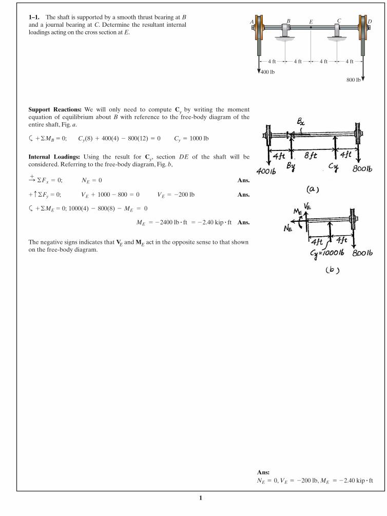
1–1. The shaft is supported by a smooth thrust bearing at Band a journal bearing at C. Determine the resultant internalloadings acting on the cross section at E.
Support Reactions: We will only need to compute Cy by writing the momentequation of equilibrium about B with reference to the free-body diagram of theentire shaft, Fig. a.
a
Internal Loadings: Using the result for Cy, section DE of the shaft will beconsidered. Referring to the free-body diagram, Fig. b,
Ans.
Ans.
a
Ans.
The negative signs indicates that VE and ME act in the opposite sense to that shownon the free-body diagram.
ME = - 2400 lb # ft = - 2.40 kip # ft
1000(4) - 800(8) - ME = 0+ ©ME = 0;
VE = -200 lbVE + 1000 - 800 = 0+ c ©Fy = 0;
NE = 0 :+ ©Fx = 0;
Cy = 1000 lbCy(8) + 400(4) - 800(12) = 0+ ©MB = 0;
A E DB C
4 ft
400 lb800 lb
4 ft 4 ft 4 ft
Ans:, , ME = - 2.40 kip # ft VE = -200 lbNE = 0
2
© 2014 Pearson Education, Inc., Upper Saddle River, NJ. All rights reserved. This material is protected under all copyright laws as they currentlyexist. No portion of this material may be reproduced, in any form or by any means, without permission in writing from the publisher.
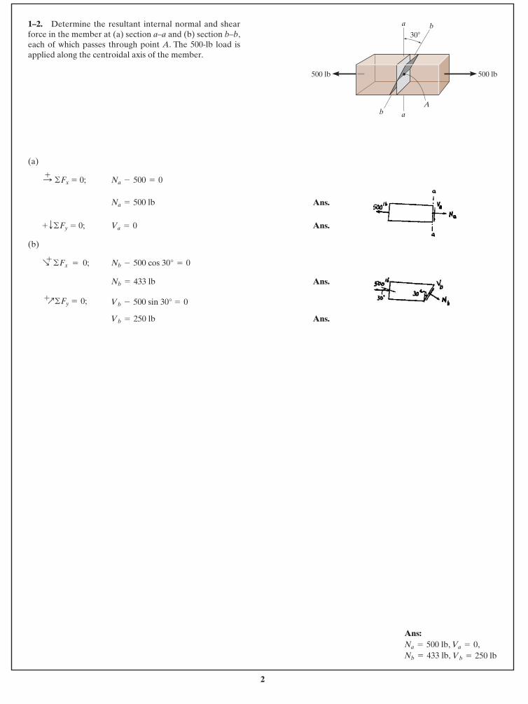
1–2. Determine the resultant internal normal and shearforce in the member at (a) section a–a and (b) section b–b,each of which passes through point A. The 500-lb load isapplied along the centroidal axis of the member.
(a)
Ans.
Ans.
(b)
Ans.
Ans.Vb = 250 lb
Vb - 500 sin 30° = 0 +Q©Fy = 0;
Nb = 433 lb
Nb - 500 cos 30° = 0R+
©Fx = 0;
Va = 0+ T©Fy = 0;
Na = 500 lb
Na - 500 = 0 :+ ©Fx = 0;
30�
A
ba
b a
500 lb500 lb
Ans:, ,
Vb = 250 lbNb = 433 lb,Va = 0Na = 500 lb
3
© 2014 Pearson Education, Inc., Upper Saddle River, NJ. All rights reserved. This material is protected under all copyright laws as they currentlyexist. No portion of this material may be reproduced, in any form or by any means, without permission in writing from the publisher.
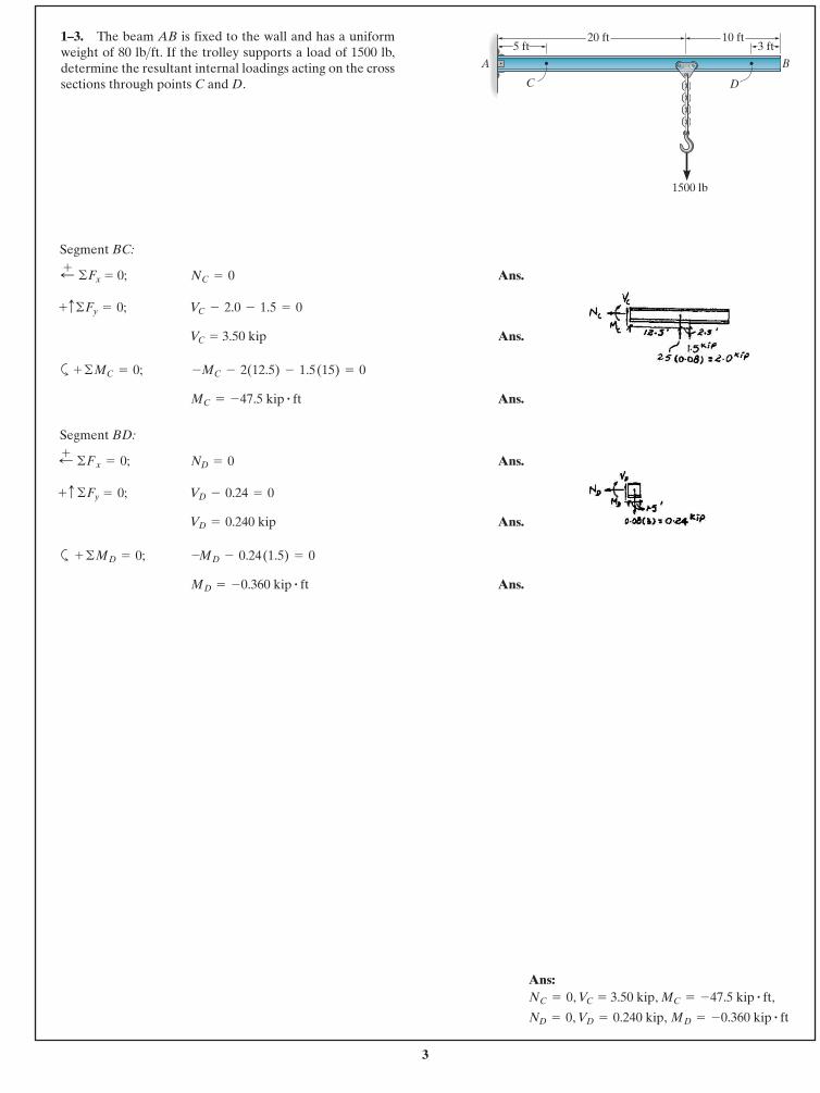
1–3. The beam AB is fixed to the wall and has a uniformweight of 80 lb ft. If the trolley supports a load of 1500 lb,determine the resultant internal loadings acting on the crosssections through points C and D.
>
Segment BC:
Ans.
Ans.
a
Ans.
Segment BD:
Ans.
Ans.
a
Ans.MD = -0.360 kip # ft
-MD - 0.24 (1.5) = 0+ ©MD = 0;
VD = 0.240 kip
VD - 0.24 = 0+ c ©Fy = 0;
ND = 0;+ © Fx = 0;
MC = -47.5 kip # ft
-MC - 2(12.5) - 1.5 (15) = 0+ ©MC = 0;
VC = 3.50 kip
VC - 2.0 - 1.5 = 0+c©Fy = 0;
NC = 0;+ ©Fx = 0;
D
5 ft20 ft
3 ft10 ft
C
BA
1500 lb
Ans:, ,
, , MD = -0.360 kip # ftVD = 0.240 kipND = 0
MC = -47.5 kip # ft,VC = 3.50 kipNC = 0
4
© 2014 Pearson Education, Inc., Upper Saddle River, NJ. All rights reserved. This material is protected under all copyright laws as they currentlyexist. No portion of this material may be reproduced, in any form or by any means, without permission in writing from the publisher.
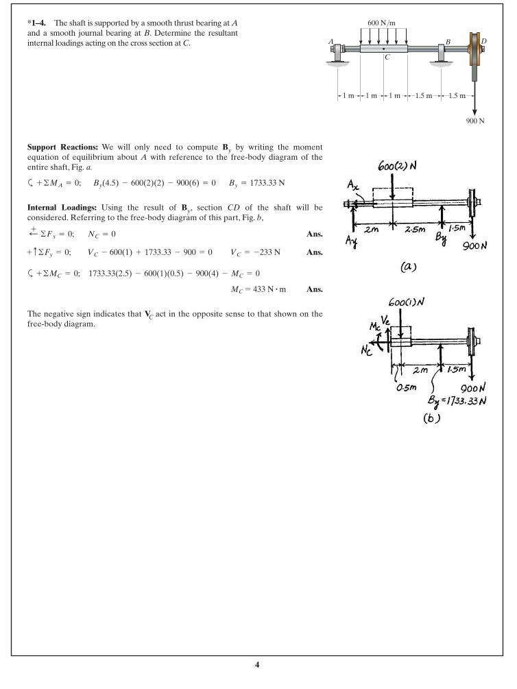
*1–4. The shaft is supported by a smooth thrust bearing at Aand a smooth journal bearing at B. Determine the resultantinternal loadings acting on the cross section at C.
Support Reactions: We will only need to compute By by writing the momentequation of equilibrium about A with reference to the free-body diagram of theentire shaft, Fig. a.
a
Internal Loadings: Using the result of By, section CD of the shaft will beconsidered. Referring to the free-body diagram of this part, Fig. b,
Ans.
Ans.
a
Ans.
The negative sign indicates that VC act in the opposite sense to that shown on thefree-body diagram.
MC = 433 N # m
1733.33(2.5) - 600(1)(0.5) - 900(4) - MC = 0+ ©MC = 0;
VC = -233 NVC - 600(1) + 1733.33 - 900 = 0+ c©Fy = 0;
NC = 0;+ ©Fx = 0;
By = 1733.33 NBy(4.5) - 600(2)(2) - 900(6) = 0+ ©MA = 0;
A DB
C
900 N
1.5 m
600 N/m
1.5 m1 m1 m1 m
5
© 2014 Pearson Education, Inc., Upper Saddle River, NJ. All rights reserved. This material is protected under all copyright laws as they currentlyexist. No portion of this material may be reproduced, in any form or by any means, without permission in writing from the publisher.
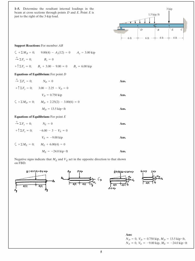
1–5. Determine the resultant internal loadings in thebeam at cross sections through points D and E. Point E isjust to the right of the 3-kip load.
Support Reactions: For member AB
a
Equations of Equilibrium: For point D
Ans.
Ans.
a
Ans.
Equations of Equilibrium: For point E
Ans.
Ans.
a
Ans.
Negative signs indicate that ME and VE act in the opposite direction to that shownon FBD.
ME = -24.0 kip # ft
+ ©ME = 0; ME + 6.00(4) = 0
VE = -9.00 kip
+ c ©Fy = 0; -6.00 - 3 - VE = 0
:+ ©Fx = 0; NE = 0
MD = 13.5 kip # ft
+ ©MD = 0; MD + 2.25(2) - 3.00(6) = 0
VD = 0.750 kip
+ c ©Fy = 0; 3.00 - 2.25 - VD = 0
:+ ©Fx = 0; ND = 0
+ c ©Fy = 0; By + 3.00 - 9.00 = 0 By = 6.00 kip
:+ ©Fx = 0; Bx = 0
+ ©MB = 0; 9.00(4) - Ay(12) = 0 Ay = 3.00 kip
6 ft 4 ft
A
4 ft
B CD E
6 ft
3 kip
1.5 kip/ ft
Ans:, ,, , ME = -24.0 kip # ft VE = -9.00 kipNE = 0
MD = 13.5 kip # ft, VD = 0.750 kipND = 0
6
© 2014 Pearson Education, Inc., Upper Saddle River, NJ. All rights reserved. This material is protected under all copyright laws as they currentlyexist. No portion of this material may be reproduced, in any form or by any means, without permission in writing from the publisher.
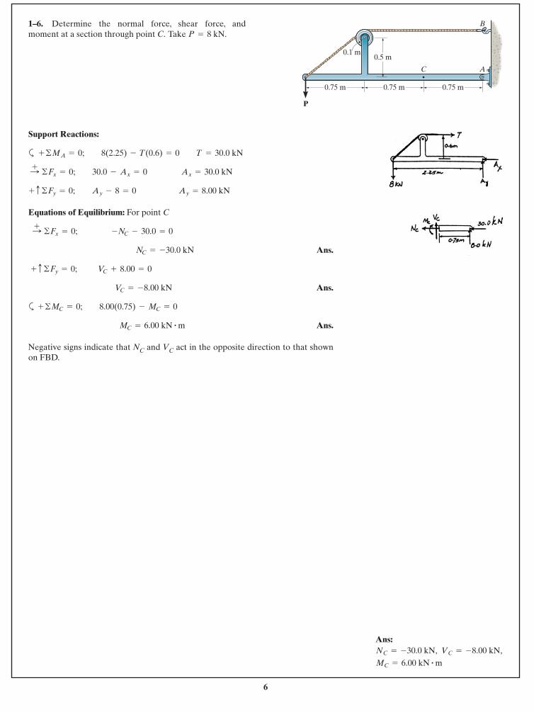
1–6. Determine the normal force, shear force, andmoment at a section through point C. Take P = 8 kN.
Support Reactions:
a
Equations of Equilibrium: For point C
Ans.
Ans.
a
Ans.
Negative signs indicate that NC and VC act in the opposite direction to that shownon FBD.
MC = 6.00 kN # m
+ ©MC = 0; 8.00(0.75) - MC = 0
VC = -8.00 kN
+ c ©Fy = 0; VC + 8.00 = 0
NC = -30.0 kN
:+ ©Fx = 0; -NC - 30.0 = 0
+ c ©Fy = 0; Ay - 8 = 0 Ay = 8.00 kN
:+ ©Fx = 0; 30.0 - Ax = 0 Ax = 30.0 kN
+ ©MA = 0; 8(2.25) - T(0.6) = 0 T = 30.0 kN
0.75 m
C
P
A
B
0.5 m0.1 m
0.75 m 0.75 m
Ans:
MC = 6.00 kN # m VC = -8.00 kN, NC = -30.0 kN,
7
© 2014 Pearson Education, Inc., Upper Saddle River, NJ. All rights reserved. This material is protected under all copyright laws as they currentlyexist. No portion of this material may be reproduced, in any form or by any means, without permission in writing from the publisher.
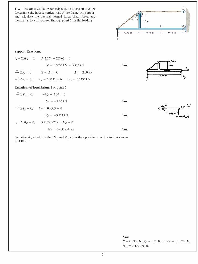
Support Reactions:
a
Ans.
Equations of Equilibrium: For point C
Ans.
Ans.
a
Ans.
Negative signs indicate that NC and VC act in the opposite direction to that shownon FBD.
MC = 0.400 kN # m
+ ©MC = 0; 0.5333(0.75) - MC = 0
VC = -0.533 kN
+ c ©Fy = 0; VC + 0.5333 = 0
NC = -2.00 kN
:+ ©Fx = 0; -NC - 2.00 = 0
+ c ©Fy = 0; Ay - 0.5333 = 0 Ay = 0.5333 kN
:+ ©Fx = 0; 2 - Ax = 0 Ax = 2.00 kN
P = 0.5333 kN = 0.533 kN
+ ©MA = 0; P(2.25) - 2(0.6) = 0
1–7. The cable will fail when subjected to a tension of 2 kN.Determine the largest vertical load P the frame will supportand calculate the internal normal force, shear force, andmoment at the cross section through point C for this loading.
0.75 m
C
P
A
B
0.5 m0.1 m
0.75 m 0.75 m
Ans:, , ,
MC = 0.400 kN # m VC = -0.533 kN NC = -2.00 kN P = 0.533 kN
8
© 2014 Pearson Education, Inc., Upper Saddle River, NJ. All rights reserved. This material is protected under all copyright laws as they currentlyexist. No portion of this material may be reproduced, in any form or by any means, without permission in writing from the publisher.
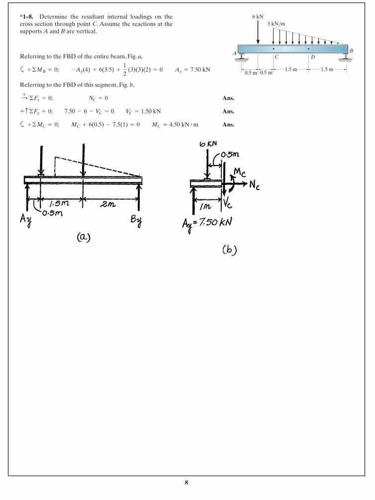
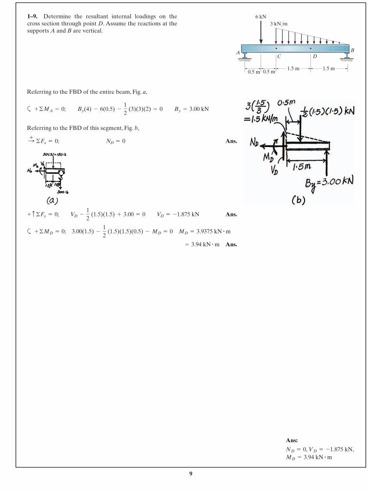
Referring to the FBD of the entire beam, Fig. a,
a
Referring to the FBD of this segment, Fig. b,
Ans.
Ans.
a Ans.+ ©MC = 0; MC + 6(0.5) - 7.5(1) = 0 MC = 4.50 kN # m
+ c ©Fy = 0; 7.50 - 6 - VC = 0 VC = 1.50 kN
:+ ©Fx = 0; NC = 0
+ ©MB = 0; -Ay(4) + 6(3.5) +
12
(3)(3)(2) = 0 Ay = 7.50 kN
*1–8. Determine the resultant internal loadings on thecross section through point C. Assume the reactions at thesupports A and B are vertical.
0.5 m 0.5 m1.5 m1.5 m
CA B
3 kN/m6 kN
D
9
© 2014 Pearson Education, Inc., Upper Saddle River, NJ. All rights reserved. This material is protected under all copyright laws as they currentlyexist. No portion of this material may be reproduced, in any form or by any means, without permission in writing from the publisher.
Referring to the FBD of the entire beam, Fig. a,
a
Referring to the FBD of this segment, Fig. b,
Ans.
Ans.
a
Ans. = 3.94 kN # m
+ ©MD = 0; 3.00(1.5) -
12
(1.5)(1.5)(0.5) - MD = 0 MD = 3.9375 kN # m
+ c ©Fy = 0; VD -
12
(1.5)(1.5) + 3.00 = 0 VD = -1.875 kN
:+ ©Fx = 0; ND = 0
+ ©MA = 0; By(4) - 6(0.5) -
12
(3)(3)(2) = 0 By = 3.00 kN
1–9. Determine the resultant internal loadings on thecross section through point D. Assume the reactions at thesupports A and B are vertical.
Ans:
MD = 3.94 kN # mND = 0, VD = -1.875 kN,
0.5 m 0.5 m1.5 m1.5 m
CA B
3 kN/m6 kN
D
10
© 2014 Pearson Education, Inc., Upper Saddle River, NJ. All rights reserved. This material is protected under all copyright laws as they currentlyexist. No portion of this material may be reproduced, in any form or by any means, without permission in writing from the publisher.
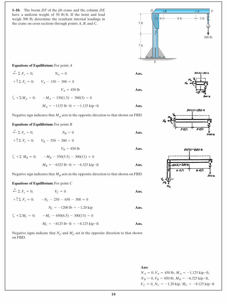
Equations of Equilibrium: For point A
Ans.
Ans.
a
Ans.
Negative sign indicates that MA acts in the opposite direction to that shown on FBD.
Equations of Equilibrium: For point B
Ans.
Ans.
a
Ans.
Negative sign indicates that MB acts in the opposite direction to that shown on FBD.
Equations of Equilibrium: For point C
Ans.
Ans.
a
Ans.
Negative signs indicate that NC and MC act in the opposite direction to that shownon FBD.
MC = -8125 lb # ft = -8.125 kip # ft
+ ©MC = 0; -MC - 650(6.5) - 300(13) = 0
NC = -1200 lb = -1.20 kip
+ c © Fy = 0; -NC - 250 - 650 - 300 = 0
;+ © Fx = 0; VC = 0
MB = -6325 lb # ft = -6.325 kip # ft
+ © MB = 0; -MB - 550(5.5) - 300(11) = 0
VB = 850 lb
+ c © Fy = 0; VB - 550 - 300 = 0
;+ © Fx = 0; NB = 0
MA = -1125 lb # ft = -1.125 kip # ft
+ ©MA = 0; -MA - 150(1.5) - 300(3) = 0
VA = 450 lb
+ c © Fy = 0; VA - 150 - 300 = 0
;+ © Fx = 0; NA = 0
1–10. The boom DF of the jib crane and the column DEhave a uniform weight of 50 lb ft. If the hoist and loadweigh 300 lb, determine the resultant internal loadings inthe crane on cross sections through points A, B, and C.
>5 ft
7 ft
C
D F
E
B A
300 lb
2 ft 8 ft 3 ft
Ans:, ,
, ,
, MC = -8.125 kip # ft NC = -1.20 kip,VC = 0
MB = -6.325 kip # ft, VB = 850 lbNB = 0
MA = -1.125 kip # ft, VA = 450 lbNA = 0
11
© 2014 Pearson Education, Inc., Upper Saddle River, NJ. All rights reserved. This material is protected under all copyright laws as they currentlyexist. No portion of this material may be reproduced, in any form or by any means, without permission in writing from the publisher.
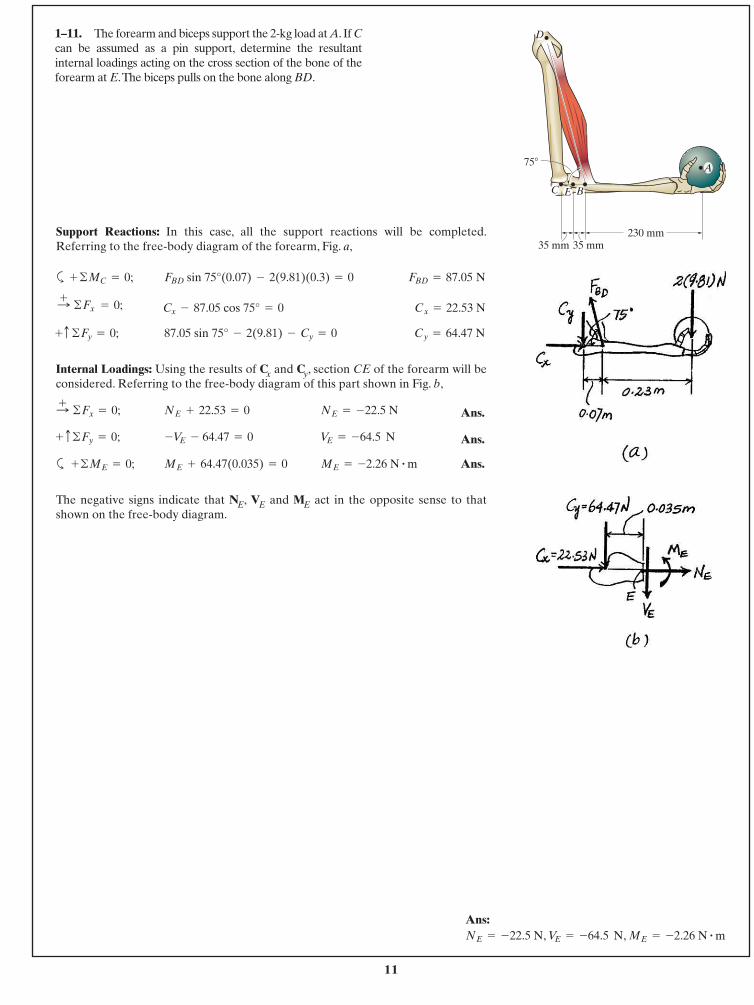
1–11. The forearm and biceps support the 2-kg load at A. If Ccan be assumed as a pin support, determine the resultantinternal loadings acting on the cross section of the bone of theforearm at E.The biceps pulls on the bone along BD.
Support Reactions: In this case, all the support reactions will be completed.Referring to the free-body diagram of the forearm, Fig. a,
a
Internal Loadings: Using the results of Cx and Cy, section CE of the forearm will beconsidered. Referring to the free-body diagram of this part shown in Fig. b,
Ans.
Ans.
a Ans.
The negative signs indicate that NE, VE and ME act in the opposite sense to thatshown on the free-body diagram.
ME = - 2.26 N # mME + 64.47(0.035) = 0+©ME = 0;
VE = - 64.5 N-VE - 64.47 = 0+ c©Fy = 0;
NE = -22.5 NNE + 22.53 = 0 :+ ©Fx = 0;
Cy = 64.47 N87.05 sin 75° - 2(9.81) - Cy = 0+c ©Fy = 0;
Cx = 22.53 NCx - 87.05 cos 75° = 0:+ ©Fx = 0;
FBD = 87.05 NFBD sin 75°(0.07) - 2(9.81)(0.3) = 0+ ©MC = 0;
75�
230 mm35 mm35 mm
C E B
D
A
Ans:, , ME = - 2.26 N # mVE = - 64.5 NNE = -22.5 N
12
© 2014 Pearson Education, Inc., Upper Saddle River, NJ. All rights reserved. This material is protected under all copyright laws as they currentlyexist. No portion of this material may be reproduced, in any form or by any means, without permission in writing from the publisher.
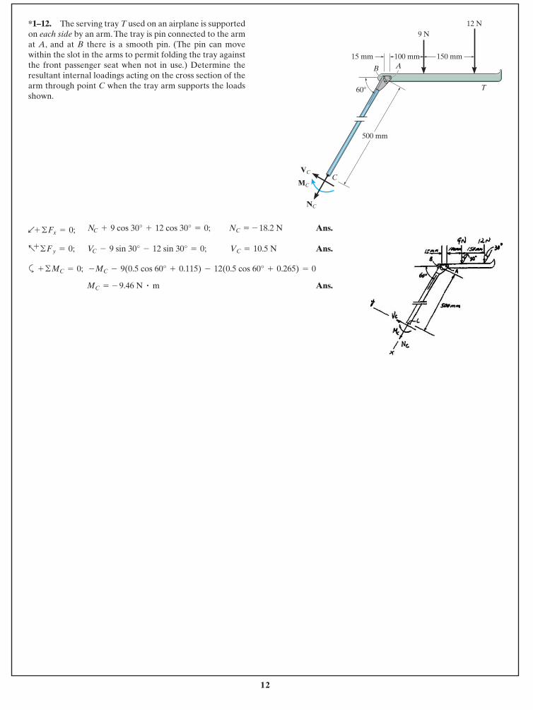
*1–12. The serving tray T used on an airplane is supportedon each side by an arm. The tray is pin connected to the armat A, and at B there is a smooth pin. (The pin can movewithin the slot in the arms to permit folding the tray againstthe front passenger seat when not in use.) Determine theresultant internal loadings acting on the cross section of thearm through point C when the tray arm supports the loadsshown.
Ans.
Ans.
a
Ans.MC = - 9.46 N # m
+ ©MC = 0; -MC - 9(0.5 cos 60° + 0.115) - 12(0.5 cos 60° + 0.265) = 0
VC = 10.5 NVC - 9 sin 30° - 12 sin 30° = 0;a+
©Fy = 0;
NC = - 18.2 NNC + 9 cos 30° + 12 cos 30° = 0; b+ ©Fx = 0;
9 N
500 mm
12 N
15 mm 150 mm
60�
AB
C
T
VC
MC
NC
100 mm
13
© 2014 Pearson Education, Inc., Upper Saddle River, NJ. All rights reserved. This material is protected under all copyright laws as they currentlyexist. No portion of this material may be reproduced, in any form or by any means, without permission in writing from the publisher.
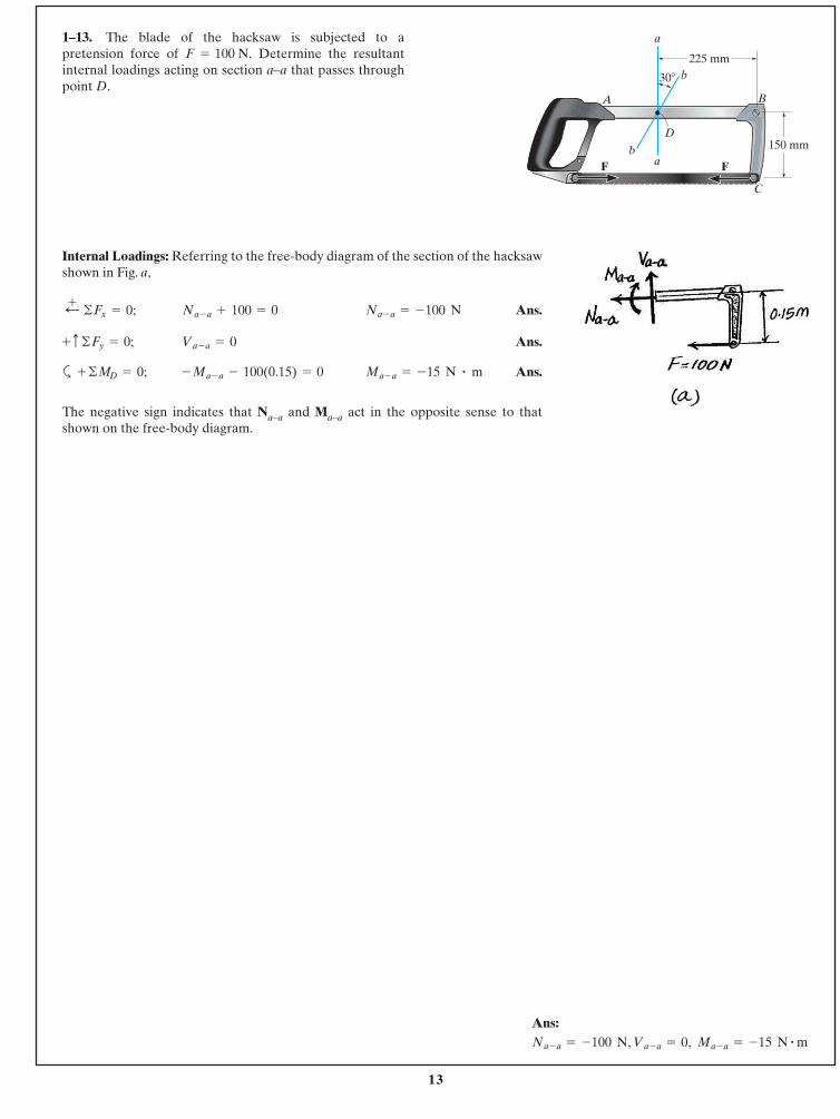
Internal Loadings: Referring to the free-body diagram of the section of the hacksawshown in Fig. a,
Ans.
Ans.
a Ans.
The negative sign indicates that Na–a and Ma–a act in the opposite sense to thatshown on the free-body diagram.
Ma - a = -15 N # m- Ma - a - 100(0.15) = 0+ ©MD = 0;
Va - a = 0+ c ©Fy = 0;
Na - a = -100 NNa - a + 100 = 0;+ ©Fx = 0;
1–13. The blade of the hacksaw is subjected to apretension force of Determine the resultantinternal loadings acting on section a–a that passes throughpoint D.
F = 100 N.
A B
C
D
F F
a
b
ba
30�
225 mm
150 mm
Ans:, , Ma - a = -15 N # mVa - a = 0Na - a = -100 N
14
© 2014 Pearson Education, Inc., Upper Saddle River, NJ. All rights reserved. This material is protected under all copyright laws as they currentlyexist. No portion of this material may be reproduced, in any form or by any means, without permission in writing from the publisher.
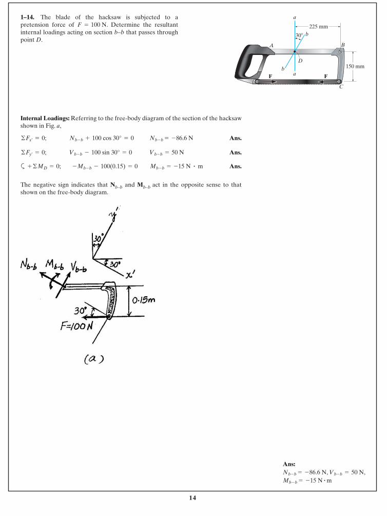
1–14. The blade of the hacksaw is subjected to apretension force of . Determine the resultantinternal loadings acting on section b–b that passes throughpoint D.
F = 100 N
Internal Loadings: Referring to the free-body diagram of the section of the hacksawshown in Fig. a,
Ans.
Ans.
a Ans.
The negative sign indicates that Nb–b and Mb–b act in the opposite sense to thatshown on the free-body diagram.
Mb - b = -15 N # m-Mb - b - 100(0.15) = 0+ ©MD = 0;
Vb - b = 50 N©Fy¿= 0; Vb - b - 100 sin 30° = 0
Nb - b = -86.6 N©Fx¿= 0; Nb - b + 100 cos 30° = 0
A B
C
D
F F
a
b
ba
30�
225 mm
150 mm
Ans:, ,
Mb - b = -15 N # mVb - b = 50 NNb - b = -86.6 N
15
© 2014 Pearson Education, Inc., Upper Saddle River, NJ. All rights reserved. This material is protected under all copyright laws as they currentlyexist. No portion of this material may be reproduced, in any form or by any means, without permission in writing from the publisher.
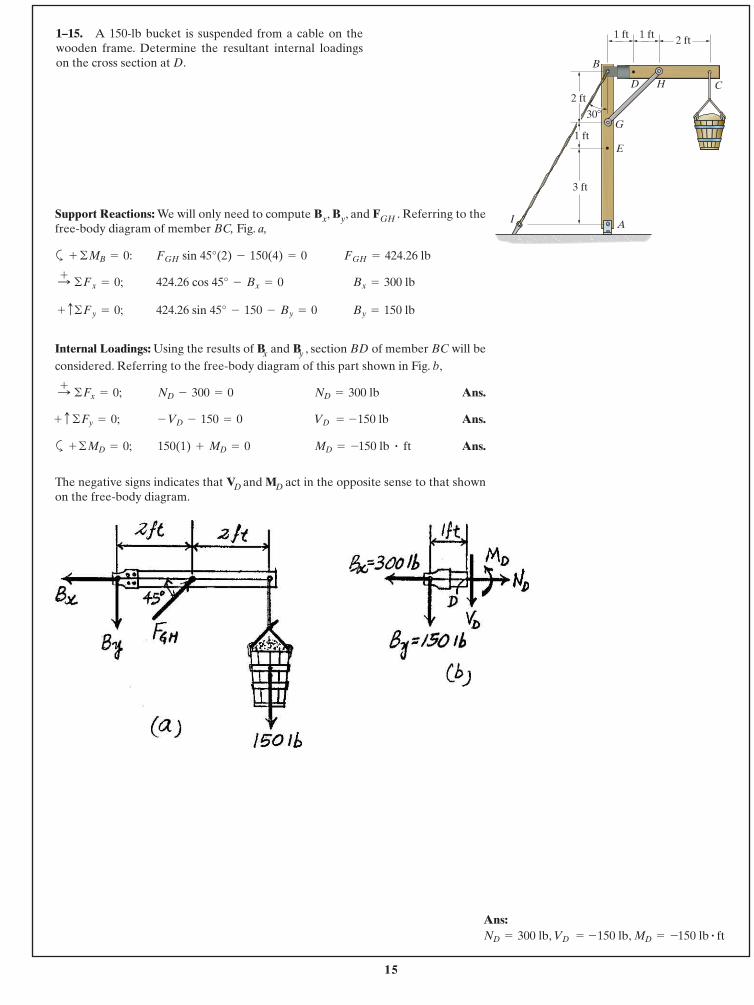
1–15. A 150-lb bucket is suspended from a cable on thewooden frame. Determine the resultant internal loadingson the cross section at D.
Support Reactions: We will only need to compute Bx, By, and FGH . Referring to thefree-body diagram of member BC, Fig. a,
a
Internal Loadings: Using the results of Bx and By , section BD of member BC will beconsidered. Referring to the free-body diagram of this part shown in Fig. b,
Ans.
Ans.
a Ans.
The negative signs indicates that VD and MD act in the opposite sense to that shownon the free-body diagram.
MD = - 150 lb # ft 150(1) + MD = 0+ ©MD = 0;
VD = -150 lb- VD - 150 = 0+ c ©Fy = 0;
ND = 300 lbND - 300 = 0:+ ©Fx = 0;
By = 150 lb424.26 sin 45° - 150 - By = 0+ c©Fy = 0;
Bx = 300 lb424.26 cos 45° - Bx = 0:+ ©Fx = 0;
FGH = 424.26 lbFGH sin 45°(2) - 150(4) = 0+ ©MB = 0:
2 ft
2 ft
3 ft
1 ft1 ft
1 ftE
D C
B
AI
30�G
H
Ans:, , MD = - 150 lb # ft VD = -150 lbND = 300 lb
16
© 2014 Pearson Education, Inc., Upper Saddle River, NJ. All rights reserved. This material is protected under all copyright laws as they currentlyexist. No portion of this material may be reproduced, in any form or by any means, without permission in writing from the publisher.
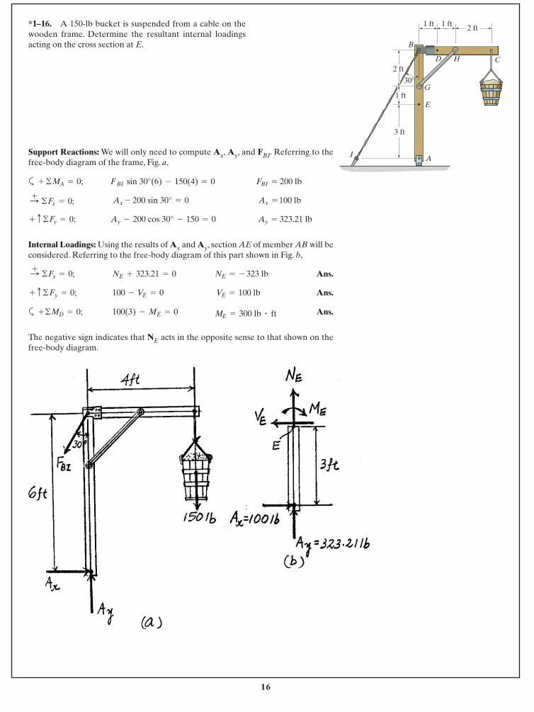
*1–16. A 150-lb bucket is suspended from a cable on thewooden frame. Determine the resultant internal loadingsacting on the cross section at E.
Support Reactions: We will only need to compute Ax, Ay, and FBI. Referring to thefree-body diagram of the frame, Fig. a,
a
Internal Loadings: Using the results of Ax and Ay, section AE of member AB will beconsidered. Referring to the free-body diagram of this part shown in Fig. b,
Ans.
Ans.
a Ans.
The negative sign indicates that NE acts in the opposite sense to that shown on thefree-body diagram.
ME = 300 lb # ft100(3) - ME = 0+©MD = 0;
VE = 100 lb100 - VE = 0+ c ©Fy = 0;
NE = - 323 lbNE + 323.21 = 0:+ ©Fx = 0;
Ay = 323.21 lbAy - 200 cos 30° - 150 = 0+ c ©Fy = 0;
Ax = 100 lbAx - 200 sin 30° = 0:+ ©Fx = 0;
FBI = 200 lb FBI sin 30°(6) - 150(4) = 0+ ©MA = 0;
2 ft
2 ft
3 ft
1 ft1 ft
1 ftE
D C
B
AI
30�G
H
17
© 2014 Pearson Education, Inc., Upper Saddle River, NJ. All rights reserved. This material is protected under all copyright laws as they currentlyexist. No portion of this material may be reproduced, in any form or by any means, without permission in writing from the publisher.
45�
1.5 m
1.5 m
3 m
45�
A
C
B
b a
ab
5 kN
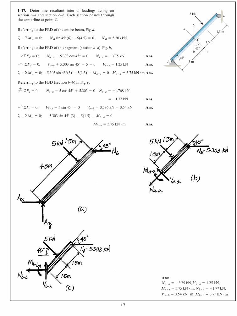
Referring to the FBD of the entire beam, Fig. a,
a
Referring to the FBD of this segment (section a–a), Fig. b,
Ans.
Ans.
a Ans.
Referring to the FBD (section b–b) in Fig. c,
Ans.
Ans.
a
Ans.Mb - b = 3.75 kN # m
+ ©MC = 0; 5.303 sin 45° (3) - 5(1.5) - Mb - b = 0
+ c ©Fy = 0; Vb - b - 5 sin 45° = 0 Vb - b = 3.536 kN = 3.54 kN
= -1.77 kN
;+ ©Fx = 0; Nb - b - 5 cos 45° + 5.303 = 0 Nb - b = -1.768 kN
+ ©MC = 0; 5.303 sin 45°(3) - 5(1.5) - Ma - a = 0 Ma - a = 3.75 kN # m
+a ©Fy¿= 0; Va - a + 5.303 sin 45° - 5 = 0 Va - a = 1.25 kN
+b©Fx¿= 0; Na - a + 5.303 cos 45° = 0 Na - a = -3.75 kN
+ ©MA = 0; NB sin 45°(6) - 5(4.5) = 0 NB = 5.303 kN
1–17. Determine resultant internal loadings acting onsection a–a and section b–b. Each section passes throughthe centerline at point C.
Ans:
Mb - b = 3.75 kN # mVb - b = 3.54 kN # m,
Nb - b = -1.77 kN,Ma - a = 3.75 kN # m,Va - a = 1.25 kN,Na - a = -3.75 kN,
18
© 2014 Pearson Education, Inc., Upper Saddle River, NJ. All rights reserved. This material is protected under all copyright laws as they currentlyexist. No portion of this material may be reproduced, in any form or by any means, without permission in writing from the publisher.
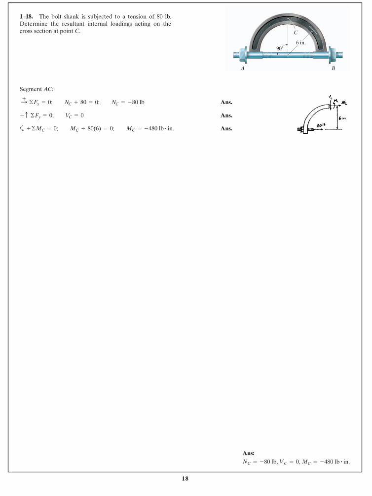
Segment AC:
Ans.
Ans.
a Ans.+ ©MC = 0; MC + 80(6) = 0; MC = -480 lb # in.
+ c ©Fy = 0; VC = 0
:+ ©Fx = 0; NC + 80 = 0; NC = -80 lb
1–18. The bolt shank is subjected to a tension of 80 lb.Determine the resultant internal loadings acting on thecross section at point C.
A B
C
90� 6 in.
Ans:MC = -480 lb # in.VC = 0,NC = -80 lb,
19
© 2014 Pearson Education, Inc., Upper Saddle River, NJ. All rights reserved. This material is protected under all copyright laws as they currentlyexist. No portion of this material may be reproduced, in any form or by any means, without permission in writing from the publisher.
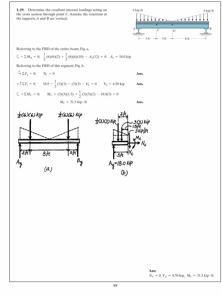
Referring to the FBD of the entire beam, Fig. a,
a
Referring to the FBD of this segment, Fig. b,
Ans.
Ans.
a
Ans. MC = 31.5 kip # ft
+ ©MC = 0; MC + (3)(3)(1.5) +
12
(3)(3)(2) - 18.0(3) = 0
+ c ©Fy = 0; 18.0 -
12
(3)(3) - (3)(3) - VC = 0 VC = 4.50 kip
:+ ©Fx = 0; NC = 0
+ ©MB = 0; 12
(6)(6)(2) +
12
(6)(6)(10) - Ay(12) = 0 Ay = 18.0 kip
1–19. Determine the resultant internal loadings acting onthe cross section through point C. Assume the reactions atthe supports A and B are vertical.
3 ft 3 ft
DCA B
6 ft
6 kip/ft6 kip/ft
Ans:
, , MC = 31.5 kip # ftVC = 4.50 kipNC = 0
20
© 2014 Pearson Education, Inc., Upper Saddle River, NJ. All rights reserved. This material is protected under all copyright laws as they currentlyexist. No portion of this material may be reproduced, in any form or by any means, without permission in writing from the publisher.
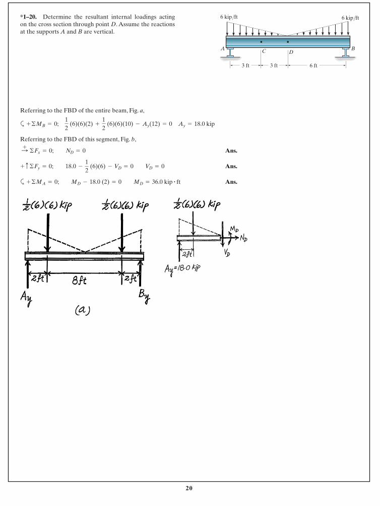
Referring to the FBD of the entire beam, Fig. a,
a
Referring to the FBD of this segment, Fig. b,
Ans.
Ans.
a Ans.+ ©MA = 0; MD - 18.0 (2) = 0 MD = 36.0 kip # ft
+ c ©Fy = 0; 18.0 -
12
(6)(6) - VD = 0 VD = 0
:+ ©Fx = 0; ND = 0
+ ©MB = 0; 12
(6)(6)(2) +
12
(6)(6)(10) - Ay(12) = 0 Ay = 18.0 kip
*1–20. Determine the resultant internal loadings actingon the cross section through point D. Assume the reactionsat the supports A and B are vertical.
3 ft 3 ft
DCA B
6 ft
6 kip/ft6 kip/ft
21
© 2014 Pearson Education, Inc., Upper Saddle River, NJ. All rights reserved. This material is protected under all copyright laws as they currentlyexist. No portion of this material may be reproduced, in any form or by any means, without permission in writing from the publisher.
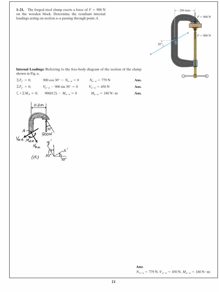
Internal Loadings: Referring to the free-body diagram of the section of the clampshown in Fig. a,
Ans.
Ans.
a Ans.+ ©MA = 0; 900(0.2) - Ma - a = 0 Ma - a = 180 N # m
©Fx¿= 0; Va - a - 900 sin 30° = 0 Va - a = 450 N
©Fy¿= 0; 900 cos 30° - Na - a = 0 Na - a = 779 N
1–21. The forged steel clamp exerts a force of Non the wooden block. Determine the resultant internalloadings acting on section a–a passing through point A.
F = 900 200 mm
a
aF � 900 N
F � 900 N
30�A
Ans:Ma - a = 180 N # m:Va - a = 450 N,Na - a = 779 N,
22
© 2014 Pearson Education, Inc., Upper Saddle River, NJ. All rights reserved. This material is protected under all copyright laws as they currentlyexist. No portion of this material may be reproduced, in any form or by any means, without permission in writing from the publisher.
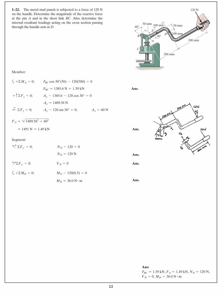
1–22. The metal stud punch is subjected to a force of 120 Non the handle. Determine the magnitude of the reactive forceat the pin A and in the short link BC. Also, determine theinternal resultant loadings acting on the cross section passingthrough the handle arm at D.
Member:
a
Ans.
Ans.
Segment:
Ans.
Ans.
a
Ans.MD = 36.0 N # m
MD - 120(0.3) = 0+©MD = 0;
VD = 0+Q©Fy¿
= 0;
ND = 120 N
ND - 120 = 0 a+©Fx¿
= 0;
= 1.49 kN= 1491 N
FA = 21489.562+ 602
Ax = 60 NAx - 120 sin 30° = 0;;+ ©Fx = 0;
Ay = 1489.56 N
Ay - 1385.6 - 120 cos 30° = 0+ c ©Fy = 0;
FBC = 1385.6 N = 1.39 kN
FBC cos 30°(50) - 120(500) = 0+©MA = 0;
60� 50 mm
100 mm
200 mm
300 mmB
C
D
120 N
50 mm 100 mm
E
30�
A
Ans:, ,
MD = 36.0 N # m VD = 0,ND = 120 N,FA = 1.49 kNFBC = 1.39 kN
23
© 2014 Pearson Education, Inc., Upper Saddle River, NJ. All rights reserved. This material is protected under all copyright laws as they currentlyexist. No portion of this material may be reproduced, in any form or by any means, without permission in writing from the publisher.
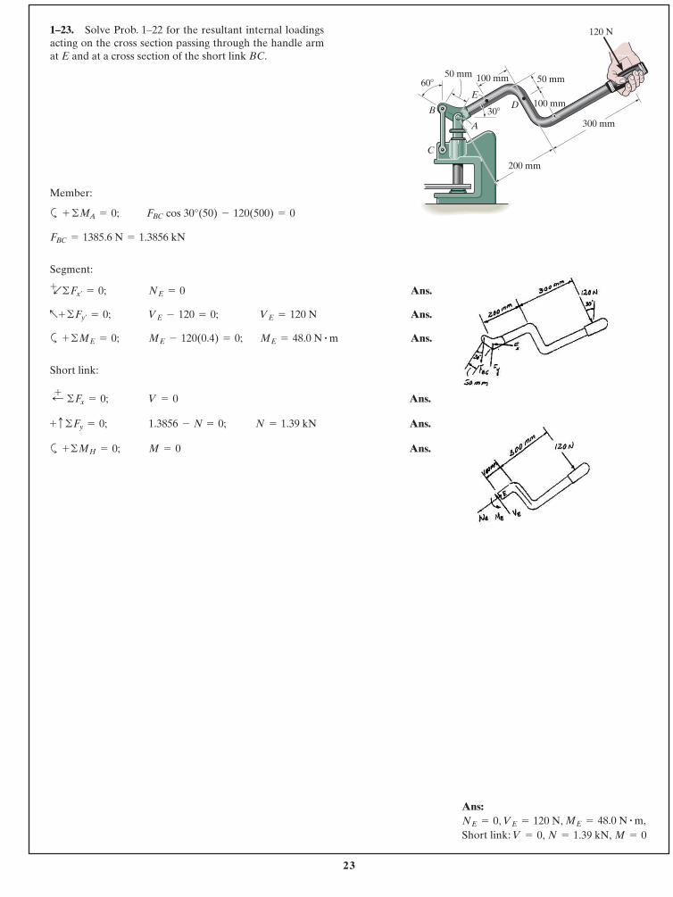
1–23. Solve Prob. 1–22 for the resultant internal loadingsacting on the cross section passing through the handle armat E and at a cross section of the short link BC.
Member:
a
Segment:
Ans.
Ans.
a Ans.
Short link:
Ans.
Ans.
a Ans.M = 0+©MH = 0;
N = 1.39 kN1.3856 - N = 0;+ c ©Fy = 0;
V = 0;+ ©Fx = 0;
ME = 48.0 N # mME - 120(0.4) = 0;+ ©ME = 0;
VE = 120 NVE - 120 = 0;a+ ©Fy¿= 0;
NE = 0 +b©Fx¿
= 0;
FBC = 1385.6 N = 1.3856 kN
FBC cos 30°(50) - 120(500) = 0+ ©MA = 0;
60� 50 mm
100 mm
200 mm
300 mmB
C
D
120 N
50 mm 100 mm
E
30�
A
Ans:, ,
Short link: M = 0N = 1.39 kN,V = 0,ME = 48.0 N # m,VE = 120 NNE = 0
24
© 2014 Pearson Education, Inc., Upper Saddle River, NJ. All rights reserved. This material is protected under all copyright laws as they currentlyexist. No portion of this material may be reproduced, in any form or by any means, without permission in writing from the publisher.
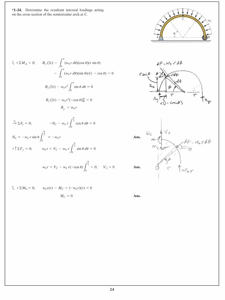
*1–24. Determine the resultant internal loadings actingon the cross section of the semicircular arch at C.
a
By
Ans.
Ans.
a
Ans.MC = 0
w0 r(r) - MC + (-w0 r)(r) = 0+ ©M0 = 0;
V2 = 0w0 r + VC - w0 r(-cos u)L
p
2
0 = 0;
w0 r + VC - w0 rL
p
2
0 sin u du = 0+ c ©Fy = 0;
NC = -w0 r sin uL
p
2
0 = -w0 r
-NC - w0 rL
p
2
0 cos u du = 0:+ ©Fx = 0;
= w0 r
By (2r) - w0 r2 (-cos u)]0p
= 0
By (2r) - w0 r2
L
p
0sin u du = 0
-
L
p
0(w0 r du)(sin u)r(1 - cos u) = 0
+ ©MA = 0; By (2r) -
L
p
0(w0 r du)(cos u)(r sin u)
C
A B
w0
u
r
25
© 2014 Pearson Education, Inc., Upper Saddle River, NJ. All rights reserved. This material is protected under all copyright laws as they currentlyexist. No portion of this material may be reproduced, in any form or by any means, without permission in writing from the publisher.
Ans.
Ans.
Ans.
Ans.
Ans.
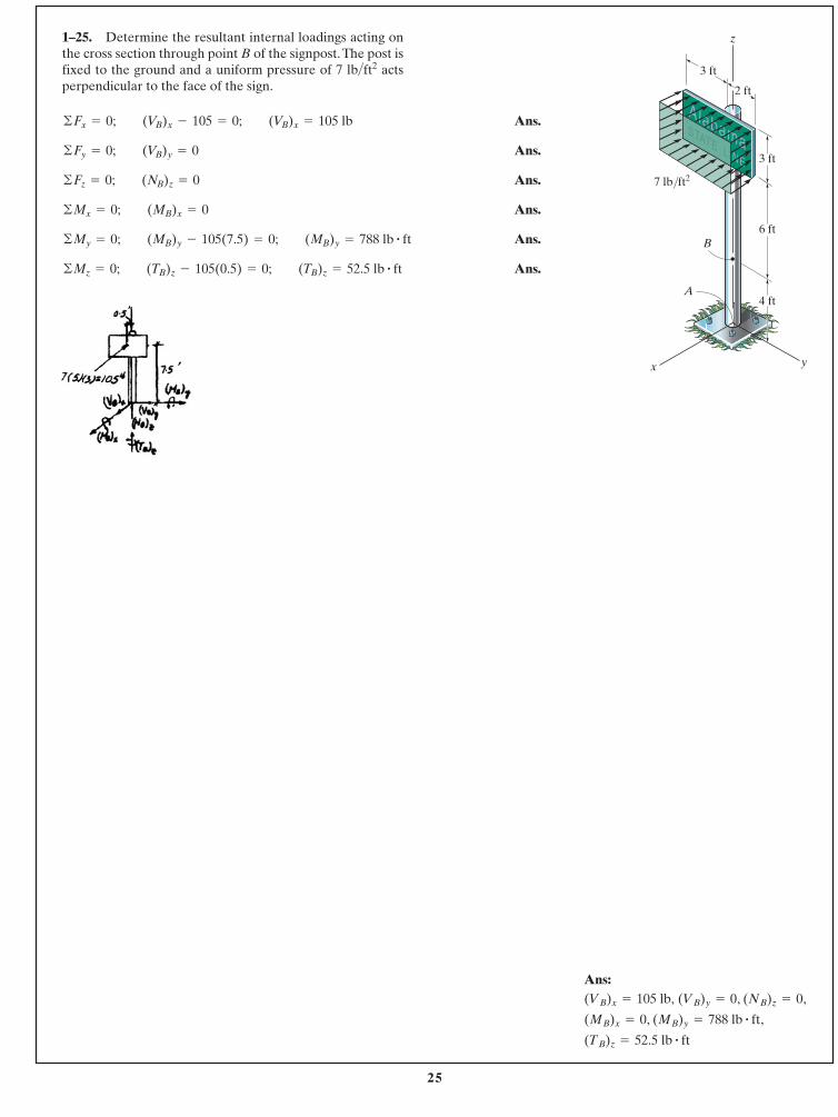
Ans.©Mz = 0; (TB)z - 105(0.5) = 0; (TB)z = 52.5 lb # ft
©My = 0; (MB)y - 105(7.5) = 0; (MB)y = 788 lb # ft
©Mx = 0; (MB)x = 0
©Fz = 0; (NB)z = 0
©Fy = 0; (VB)y = 0
©Fx = 0; (VB)x - 105 = 0; (VB)x = 105 lb
1–25. Determine the resultant internal loadings acting onthe cross section through point B of the signpost.The post isfixed to the ground and a uniform pressure of 7 > actsperpendicular to the face of the sign.
ft2lb
4 ft
z
y
6 ft
x
B
A
3 ft
2 ft
3 ft
7 lb/ft2
Ans:, ,
, ,
(TB)z = 52.5 lb # ft
(MB)y = 788 lb # ft(MB)x = 0
(NB)z = 0(VB)y = 0(VB)x = 105 lb,
26
© 2014 Pearson Education, Inc., Upper Saddle River, NJ. All rights reserved. This material is protected under all copyright laws as they currentlyexist. No portion of this material may be reproduced, in any form or by any means, without permission in writing from the publisher.
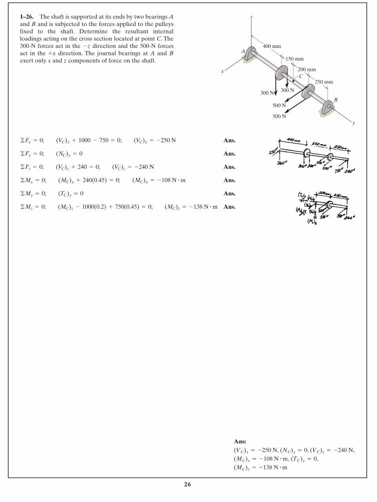
1–26. The shaft is supported at its ends by two bearings Aand B and is subjected to the forces applied to the pulleysfixed to the shaft. Determine the resultant internalloadings acting on the cross section located at point C. The300-N forces act in the z direction and the 500-N forcesact in the x direction. The journal bearings at A and Bexert only x and z components of force on the shaft.
+
-
y
B
C
400 mm
150 mm
200 mm
250 mm
A
x
z
300 N 300 N
500 N
500 N
Ans.
Ans.
Ans.
Ans.
Ans.
Ans.©Mz = 0; (MC)z - 1000(0.2) + 750(0.45) = 0; (MC)z = -138 N # m
©My = 0; (TC)y = 0
©Mx = 0; (MC)x + 240(0.45) = 0; (MC)x = -108 N # m
©Fz = 0; (VC)z + 240 = 0; (VC)z = -240 N
©Fy = 0; (NC)y = 0
©Fx = 0; (VC)x + 1000 - 750 = 0; (VC)x = -250 N
Ans:, , ,
,(MC)z = -138 N # m
(TC)y = 0(MC)x = -108 N # m,(VC)z = -240 N(NC)y = 0(VC)x = -250 N
27
© 2014 Pearson Education, Inc., Upper Saddle River, NJ. All rights reserved. This material is protected under all copyright laws as they currentlyexist. No portion of this material may be reproduced, in any form or by any means, without permission in writing from the publisher.
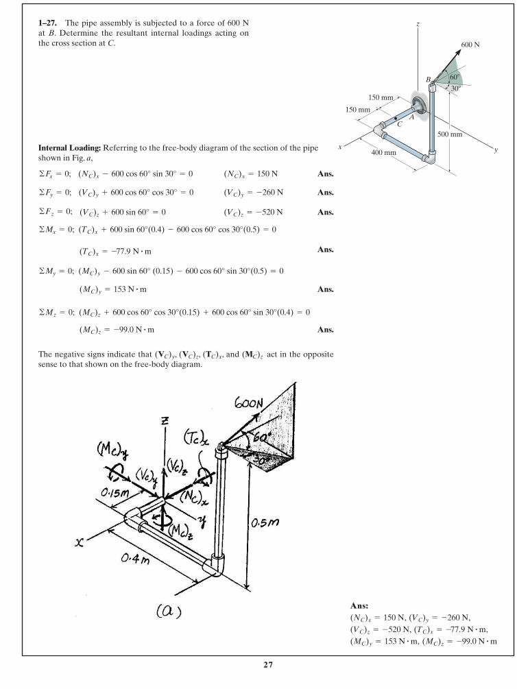
1–27. The pipe assembly is subjected to a force of 600 N at B. Determine the resultant internal loadings acting onthe cross section at C.
Internal Loading: Referring to the free-body diagram of the section of the pipeshown in Fig. a,
Ans.
Ans.
Ans.
Ans.
Ans.
Ans.
The negative signs indicate that and act in the oppositesense to that shown on the free-body diagram.
(MC)z(VC)y, (VC)z, (TC)x,
(MC)z = -99.0 N # m
(MC)z + 600 cos 60° cos 30°(0.15) + 600 cos 60° sin 30°(0.4) = 0©Mz = 0;
(MC)y = 153 N # m
(MC)y - 600 sin 60° (0.15) - 600 cos 60° sin 30°(0.5) = 0©My = 0;
(TC)x = -77.9 N # m
(TC)x + 600 sin 60°(0.4) - 600 cos 60° cos 30°(0.5) = 0©Mx = 0;
(VC)z = -520 N(VC)z + 600 sin 60° = 0©Fz = 0;
(VC)y = -260 N(VC)y + 600 cos 60° cos 30° = 0©Fy = 0;
(NC)x = 150 N(NC)x - 600 cos 60° sin 30° = 0©Fx = 0;
AC
B
yx
z
400 mm
150 mm
500 mm
600 N
150 mm
30�
60�
Ans:Ans:,, ,,
,,(MC)z = -99.0 N # m(MC)y = 153 N # m,
(TC)x = -77.9 N # m,(VC)z = -520 N(VC)y = -260 N(NC)x = 150 N
28
© 2014 Pearson Education, Inc., Upper Saddle River, NJ. All rights reserved. This material is protected under all copyright laws as they currentlyexist. No portion of this material may be reproduced, in any form or by any means, without permission in writing from the publisher.
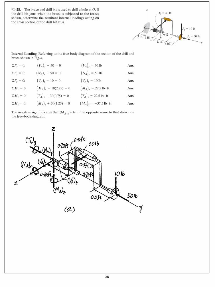
Internal Loading: Referring to the free-body diagram of the section of the drill andbrace shown in Fig. a,
Ans.
Ans.
Ans.
Ans.
Ans.
Ans.
The negative sign indicates that (MA)z acts in the opposite sense to that shown onthe free-body diagram.
©Mz = 0; AMA Bz + 30(1.25) = 0 AMA Bz = -37.5 lb # ft
©My = 0; ATA By - 30(0.75) = 0 ATA By = 22.5 lb # ft
©Mx = 0; AMA Bx - 10(2.25) = 0 AMA Bx = 22.5 lb # ft
©Fz = 0; AVA Bz - 10 = 0 AVA Bz = 10 lb
©Fy = 0; ANA By - 50 = 0 ANA By = 50 lb
©Fx = 0; AVA Bx - 30 = 0 AVA Bx = 30 lb
*1–28. The brace and drill bit is used to drill a hole at O. Ifthe drill bit jams when the brace is subjected to the forcesshown, determine the resultant internal loadings acting onthe cross section of the drill bit at A.
z
xy
AO
9 in.6 in.
6 in. 6 in.
9 in.3 in.
Fx � 30 lb
Fy � 50 lb
Fz � 10 lb
29
© 2014 Pearson Education, Inc., Upper Saddle River, NJ. All rights reserved. This material is protected under all copyright laws as they currentlyexist. No portion of this material may be reproduced, in any form or by any means, without permission in writing from the publisher.
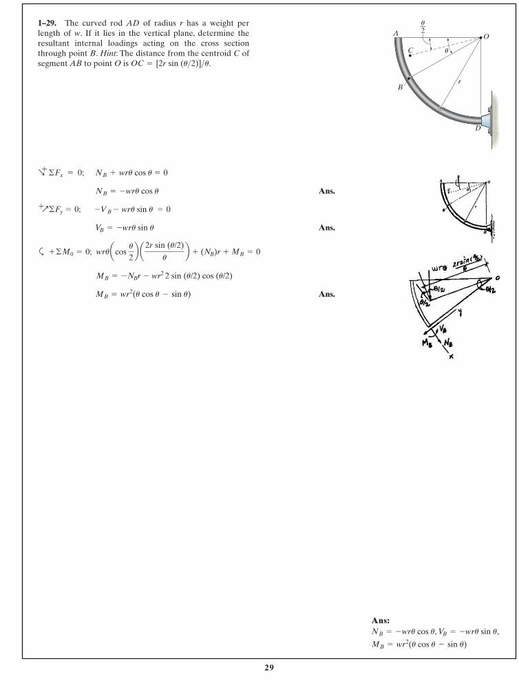
1–29. The curved rod AD of radius r has a weight perlength of w. If it lies in the vertical plane, determine theresultant internal loadings acting on the cross sectionthrough point B. Hint: The distance from the centroid C ofsegment AB to point O is OC = [2r sin (u>2)]>u.
Ans.
Ans.
a
Ans.MB = wr2(u cos u - sin u)
MB = -NBr - wr2 2 sin (u/2) cos (u/2)
wruacos u
2b a2r sin (u/2)
ub + (NB)r + MB = 0+ ©M0 = 0;
VB = -wru sin u
-VB - wru sin u = 0 +Q©Fy = 0;
NB = -wru cos u
NB + wru cos u = 0R+
©Fx = 0;
O
r
C
B
D
A
u
u2
Ans:Ans:, ,
MB = wr2(u cos u - sin u)
VB = -wru sin uNB = -wru cos u
30
© 2014 Pearson Education, Inc., Upper Saddle River, NJ. All rights reserved. This material is protected under all copyright laws as they currentlyexist. No portion of this material may be reproduced, in any form or by any means, without permission in writing from the publisher.
(1)
(2)
(3)
(4)
Since is can add, then ,
Eq. (1) becomes
Neglecting the second order term,
QED
Eq. (2) becomes
Neglecting the second order term,
QED
Eq. (3) becomes
Neglecting the second order term,
QED
Eq. (4) becomes
Neglecting the second order term,
QEDdM
du= -T
Tdu + dM = 0
Tdu + dM +
dTdu
2= 0
dT
du= M
Mdu - dT = 0
Mdu - dT +
dMdu
2= 0
dV
du= -N
Ndu + dV = 0
Ndu + dV +
dNdu
2= 0
dN
du= V
Vdu - dN = 0
Vdu - dN +
dVdu
2= 0
cos du
2= 1sin
du
2=
du
2du
2
T sin du
2- M cos
du
2+ (T + dT) sin
du
2+ (M + dM) cos
du
2= 0
©My = 0;
T cos du
2+ M sin
du
2- (T + dT) cos
du
2+ (M + dM) sin
du
2= 0
©Mx = 0;
N sin du
2- V cos
du
2+ (N + dN) sin
du
2+ (V + dV) cos
du
2= 0
©Fy = 0;
N cos du
2+ V sin
du
2- (N + dN) cos
du
2+ (V + dV) sin
du
2= 0
©Fx = 0;
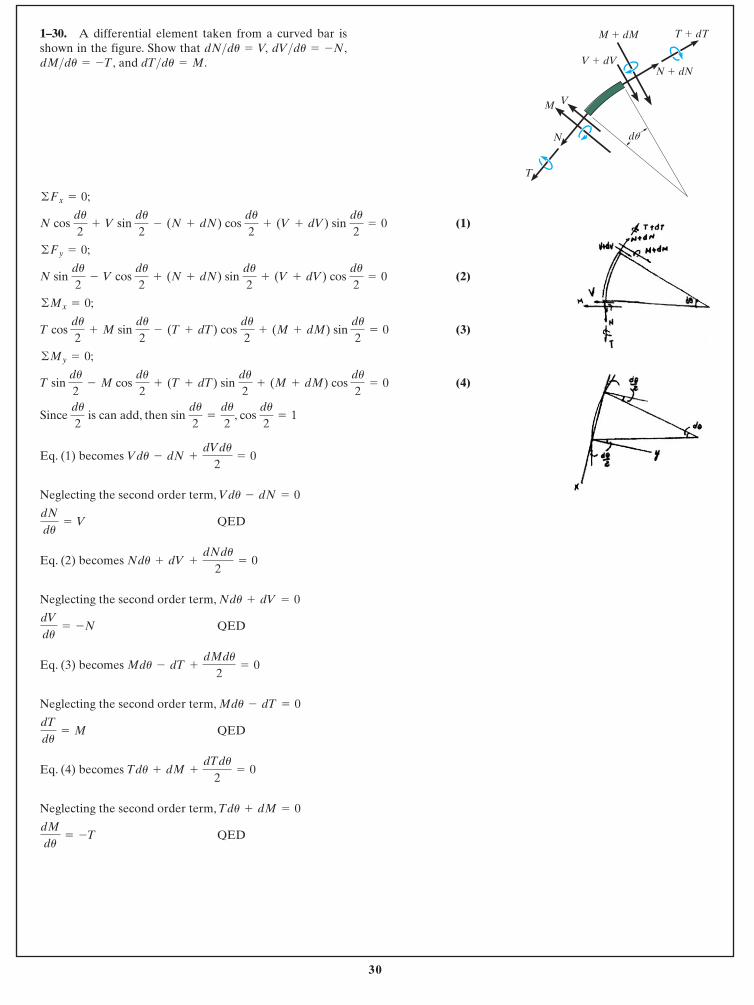
1–30. A differential element taken from a curved bar isshown in the figure. Show that
and dT>du = M.dM>du = -T,dV>du = -N,dN>du = V,
M V
N du
M � dM T � dT
N � dNV � dV
T
31
© 2014 Pearson Education, Inc., Upper Saddle River, NJ. All rights reserved. This material is protected under all copyright laws as they currentlyexist. No portion of this material may be reproduced, in any form or by any means, without permission in writing from the publisher.
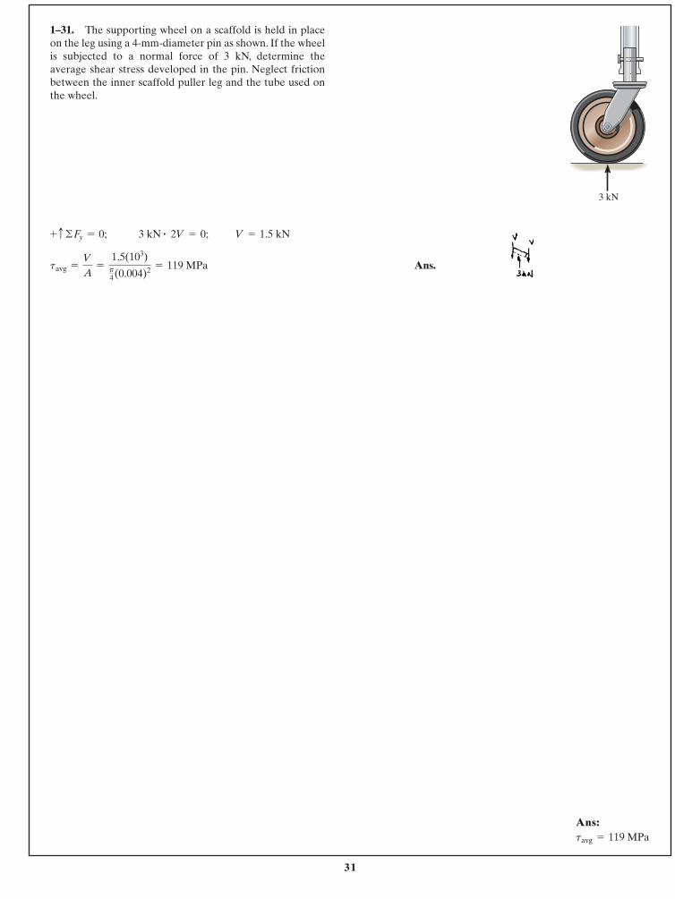
1–31. The supporting wheel on a scaffold is held in placeon the leg using a 4-mm-diameter pin as shown. If the wheelis subjected to a normal force of 3 kN, determine theaverage shear stress developed in the pin. Neglect frictionbetween the inner scaffold puller leg and the tube used onthe wheel.
Ans.tavg =
V
A=
1.5(103)p4(0.004)2 = 119 MPa
V = 1.5 kN3 kN # 2V = 0;+ c ©Fy = 0;
3 kN
Ans:Ans:tavg = 119 MPa
32
© 2014 Pearson Education, Inc., Upper Saddle River, NJ. All rights reserved. This material is protected under all copyright laws as they currentlyexist. No portion of this material may be reproduced, in any form or by any means, without permission in writing from the publisher.
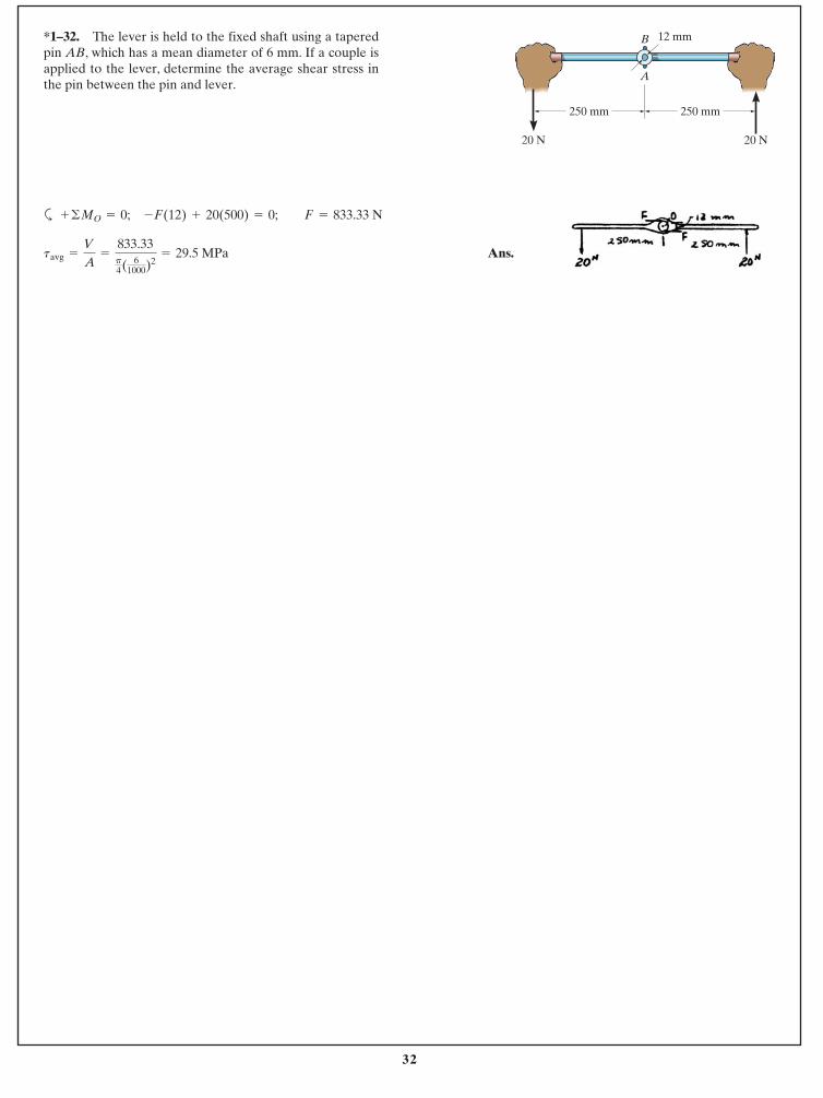
a
Ans.tavg =
V
A=
833.33p4( 6
1000)2= 29.5 MPa
+ ©MO = 0; -F(12) + 20(500) = 0; F = 833.33 N
*1–32. The lever is held to the fixed shaft using a taperedpin AB, which has a mean diameter of 6 mm. If a couple isapplied to the lever, determine the average shear stress inthe pin between the pin and lever.
20 N 20 N
250 mm 250 mm
12 mm
A
B

33
© 2014 Pearson Education, Inc., Upper Saddle River, NJ. All rights reserved. This material is protected under all copyright laws as they currentlyexist. No portion of this material may be reproduced, in any form or by any means, without permission in writing from the publisher.
Equations of Equilibrium:
Average Normal Stress and Shear Stress: Area at plane, .
Ans.
Ans. =
P
A sin u cos u =
P
2A sin 2u
tavg =
V
A¿
=
P cos uA
sin u
savg =
N
A¿
=
P sin uA
sin u
=
P
A sin2 u
A¿ =
A
sin uu
Q+ ©Fy = 0; N - P sin u = 0 N = P sin u
R+ ©Fx = 0; V - P cos u = 0 V = P cos u
1–33. The bar has a cross-sectional area A and is subjectedto the axial load P. Determine the average normal andaverage shear stresses acting over the shaded section, whichis oriented at from the horizontal. Plot the variation ofthese stresses as a function of u 10 … u … 90°2.
u
P
u
P
A
Ans:Ans:
tavg =
P
2A sin 2usavg =
P
A sin2 u,
34
© 2014 Pearson Education, Inc., Upper Saddle River, NJ. All rights reserved. This material is protected under all copyright laws as they currentlyexist. No portion of this material may be reproduced, in any form or by any means, without permission in writing from the publisher.
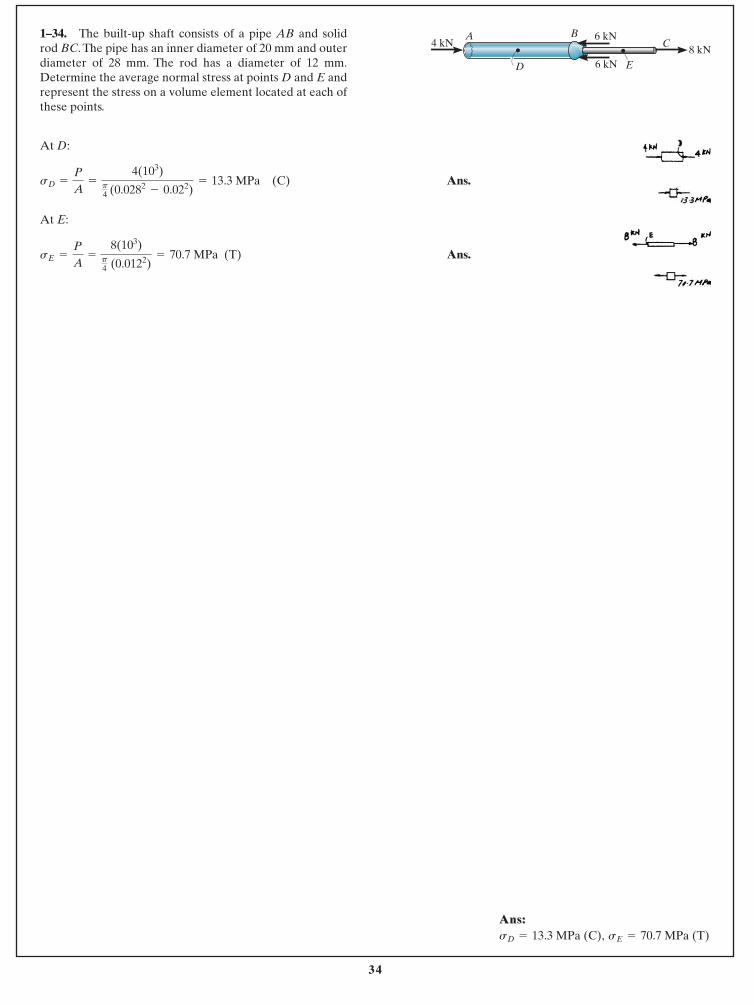
At D:
Ans.
At E:
Ans.sE =
P
A=
8(103)p4 (0.0122)
= 70.7 MPa (T)
sD =
P
A=
4(103)p4 (0.0282
- 0.022)= 13.3 MPa (C)
1–34. The built-up shaft consists of a pipe AB and solidrod BC. The pipe has an inner diameter of 20 mm and outerdiameter of 28 mm. The rod has a diameter of 12 mm.Determine the average normal stress at points D and E andrepresent the stress on a volume element located at each ofthese points.
C
ED
A4 kN
8 kN
B 6 kN
6 kN
Ans:Ans:sE = 70.7 MPa (T)sD = 13.3 MPa (C),
35
© 2014 Pearson Education, Inc., Upper Saddle River, NJ. All rights reserved. This material is protected under all copyright laws as they currentlyexist. No portion of this material may be reproduced, in any form or by any means, without permission in writing from the publisher.
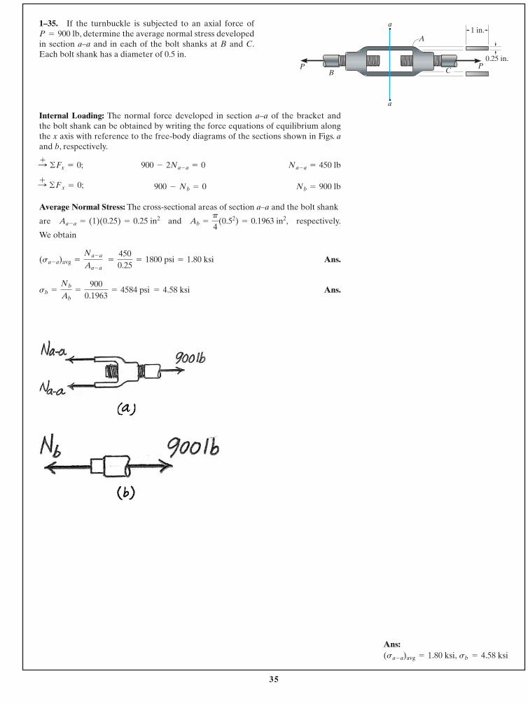
1–35. If the turnbuckle is subjected to an axial force of, determine the average normal stress developed
in section a–a and in each of the bolt shanks at B and C.Each bolt shank has a diameter of 0.5 in.
P = 900 lb
Internal Loading: The normal force developed in section a–a of the bracket and the bolt shank can be obtained by writing the force equations of equilibrium alongthe x axis with reference to the free-body diagrams of the sections shown in Figs. aand b, respectively.
Average Normal Stress: The cross-sectional areas of section a–a and the bolt shank
are and respectively.
We obtain
Ans.
Ans.sb =
Nb
Ab=
9000.1963
= 4584 psi = 4.58 ksi
(sa - a)avg =
Na - a
Aa - a =
4500.25
= 1800 psi = 1.80 ksi
Ab =
p
4(0.52) = 0.1963 in2,Aa - a = (1)(0.25) = 0.25 in2
Nb = 900 lb900 - Nb = 0:+ ©Fx = 0;
Na - a = 450 lb900 - 2Na - a = 0:+ ©Fx = 0;
a
A
BP P
C
a
1 in.
0.25 in.
Ans:sb = 4.58 ksi(sa - a)avg = 1.80 ksi,
36
© 2014 Pearson Education, Inc., Upper Saddle River, NJ. All rights reserved. This material is protected under all copyright laws as they currentlyexist. No portion of this material may be reproduced, in any form or by any means, without permission in writing from the publisher.
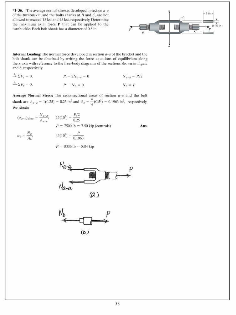
Internal Loading: The normal force developed in section a–a of the bracket and thebolt shank can be obtained by writing the force equations of equilibrium along the x axis with reference to the free-body diagrams of the sections shown in Figs. aand b, respectively.
Average Normal Stress: The cross-sectional areas of section a–a and the bolt
shank are and , respectively.
We obtain
Ans.
P = 8336 lb = 8.84 kip
45(103) =
P
0.1963sb =
Nb
Ab;
P = 7500 lb = 7.50 kip (controls)
15(103) =
P>20.25
(sa - a)allow =
Na - a
Aa - a;
Ab =
p
4 (0.52) = 0.1963 in2Aa - a = 1(0.25) = 0.25 in2
Nb = PP - Nb = 0:+ ©Fx = 0;
Na - a = P>2P - 2Na - a = 0:+ ©Fx = 0;
*1–36. The average normal stresses developed in section a–aof the turnbuckle, and the bolts shanks at B and C, are notallowed to exceed 15 ksi and 45 ksi, respectively. Determinethe maximum axial force P that can be applied to theturnbuckle. Each bolt shank has a diameter of 0.5 in.
a
A
BP P
C
a
1 in.
0.25 in.
37
© 2014 Pearson Education, Inc., Upper Saddle River, NJ. All rights reserved. This material is protected under all copyright laws as they currentlyexist. No portion of this material may be reproduced, in any form or by any means, without permission in writing from the publisher.
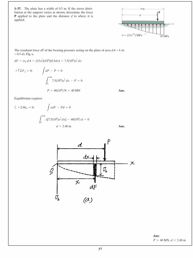
The resultant force dF of the bearing pressure acting on the plate of area dA = b dx= 0.5 dx, Fig. a,
Ans.
Equilibrium requires
a
Ans. d = 2.40 m
L
4 m
0x[7.5(106)x
12 dx] - 40(106) d = 0
+ ©MO = 0; L
xdF - Pd = 0
P = 40(106) N = 40 MN
L
4 m
07.5(106)x
12 dx - P = 0
+ c ©Fy = 0; L
dF - P = 0
dF = sb dA = (15x12)(106)(0.5dx) = 7.5(106)x
12 dx
1–37. The plate has a width of 0.5 m. If the stress distri-bution at the support varies as shown, determine the force P applied to the plate and the distance d to where it isapplied.
4 m
30 MPa
Pd
� (15x ) MPa1/2s
x
Ans: d = 2.40 m P = 40 MN,
38
© 2014 Pearson Education, Inc., Upper Saddle River, NJ. All rights reserved. This material is protected under all copyright laws as they currentlyexist. No portion of this material may be reproduced, in any form or by any means, without permission in writing from the publisher.
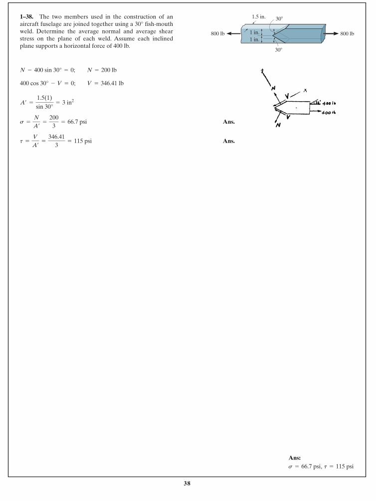
Ans.
Ans.t =
V
A¿
=
346.413
= 115 psi
s =
N
A¿
=
2003
= 66.7 psi
A¿ =
1.5(1)
sin 30°= 3 in2
400 cos 30° - V = 0; V = 346.41 lb
N - 400 sin 30° = 0; N = 200 lb
1–38. The two members used in the construction of anaircraft fuselage are joined together using a 30° fish-mouthweld. Determine the average normal and average shearstress on the plane of each weld. Assume each inclinedplane supports a horizontal force of 400 lb.
800 lb 800 lb
30�
1 in.1 in.
1.5 in. 30�
Ans:t = 115 psi s = 66.7 psi,
39
© 2014 Pearson Education, Inc., Upper Saddle River, NJ. All rights reserved. This material is protected under all copyright laws as they currentlyexist. No portion of this material may be reproduced, in any form or by any means, without permission in writing from the publisher.
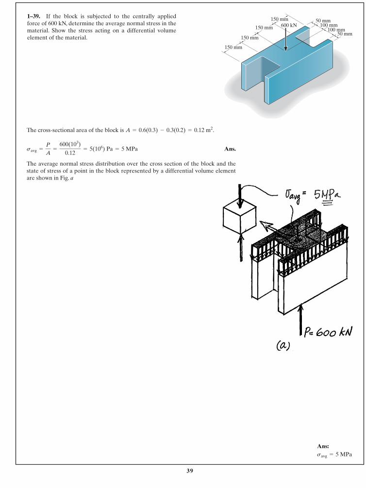
The cross-sectional area of the block is .
Ans.
The average normal stress distribution over the cross section of the block and thestate of stress of a point in the block represented by a differential volume elementare shown in Fig. a
savg =
P
A=
600(103)
0.12= 5(106) Pa = 5 MPa
A = 0.6(0.3) - 0.3(0.2) = 0.12 m2
1–39. If the block is subjected to the centrally appliedforce of 600 kN, determine the average normal stress in thematerial. Show the stress acting on a differential volumeelement of the material.
50 mm
150 mm
150 mm50 mm
100 mm100 mm
600 kN150 mm
150 mm
Ans:savg = 5 MPa
40
© 2014 Pearson Education, Inc., Upper Saddle River, NJ. All rights reserved. This material is protected under all copyright laws as they currentlyexist. No portion of this material may be reproduced, in any form or by any means, without permission in writing from the publisher.
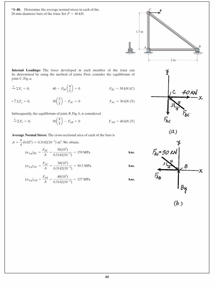
*1–40. Determine the average normal stress in each of the20-mm diameter bars of the truss. Set .P = 40 kN
Internal Loadings: The force developed in each member of the truss can be determined by using the method of joints. First, consider the equilibrium of joint C, Fig. a,
Subsequently, the equilibrium of joint B, Fig. b, is considered
Average Normal Stress: The cross-sectional area of each of the bars is
We obtain,
Ans.
Ans.
Ans.(savg)AB =
FAB
A=
40(103)
0.3142(10- 3)= 127 MPa
(savg)AC =
FAC
A=
30(103)
0.3142(10- 3)= 95.5 MPa
(savg)BC =
FBC
A=
50(103)
0.3142(10- 3)= 159 MPa
A =
p
4 (0.022) = 0.3142(10- 3) m2.
FAB = 40 kN (T)50a45b - FAB = 0:+ ©Fx = 0;
FAC = 30 kN (T)50a35b - FAC = 0+ c ©Fy = 0;
FBC = 50 kN (C)40 - FBCa45b = 0:+ ©Fx = 0;
P
1.5 m
2 m
C
A B
41
© 2014 Pearson Education, Inc., Upper Saddle River, NJ. All rights reserved. This material is protected under all copyright laws as they currentlyexist. No portion of this material may be reproduced, in any form or by any means, without permission in writing from the publisher.
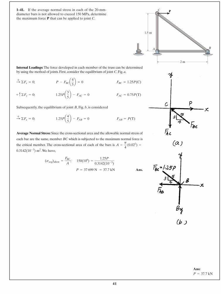
Internal Loadings: The force developed in each member of the truss can be determinedby using the method of joints. First, consider the equilibrium of joint C, Fig. a,
Subsequently, the equilibrium of joint B, Fig. b, is considered
Average Normal Stress: Since the cross-sectional area and the allowable normal stress of
each bar are the same, member BC which is subjected to the maximum normal force is
the critical member. The cross-sectional area of each of the bars is
. We have,
Ans.P = 37 699 N = 37.7 kN
150(106) =
1.25P
0.3142(10- 3)(savg)allow =
FBC
A;
0.3142(10- 3) m2
A =
p
4 (0.022) =
FAB = P(T)1.25Pa45b - FAB = 0:+ ©Fx = 0;
FAC = 0.75P(T)1.25Pa35b - FAC = 0+ c ©Fy = 0;
FBC = 1.25P(C)P - FBCa45b = 0:+ ©Fx = 0;
1–41. If the average normal stress in each of the 20-mm-diameter bars is not allowed to exceed 150 MPa, determinethe maximum force P that can be applied to joint C.
P
1.5 m
2 m
C
A B
Ans:P = 37.7 kN
42
© 2014 Pearson Education, Inc., Upper Saddle River, NJ. All rights reserved. This material is protected under all copyright laws as they currentlyexist. No portion of this material may be reproduced, in any form or by any means, without permission in writing from the publisher.
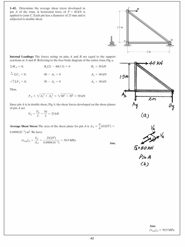
1–42. Determine the average shear stress developed inpin A of the truss. A horizontal force of isapplied to joint C. Each pin has a diameter of 25 mm and issubjected to double shear.
P = 40 kN
Internal Loadings: The forces acting on pins A and B are equal to the supportreactions at A and B. Referring to the free-body diagram of the entire truss, Fig. a,
Thus,
Since pin A is in double shear, Fig. b, the shear forces developed on the shear planesof pin A are
Average Shear Stress: The area of the shear plane for pin A is
. We have
Ans.(tavg)A =
VA
AA=
25(103)
0.4909(10- 3)= 50.9 MPa
0.4909(10- 3) m2
AA =
p
4 (0.0252) =
VA =
FA
2=
502
= 25 kN
= 2402+ 302
= 50 kNFA = 2Ax2 + Ay
2
Ay = 30 kN30 - Ay = 0 + c ©Fy = 0;
Ax = 40 kN40 - Ax = 0 :+ ©Fx = 0;
By = 30 kNBy(2) - 40(1.5) = 0©MA = 0;
P
1.5 m
2 m
C
A B
Ans:(tavg)A = 50.9 MPa
43
© 2014 Pearson Education, Inc., Upper Saddle River, NJ. All rights reserved. This material is protected under all copyright laws as they currentlyexist. No portion of this material may be reproduced, in any form or by any means, without permission in writing from the publisher.
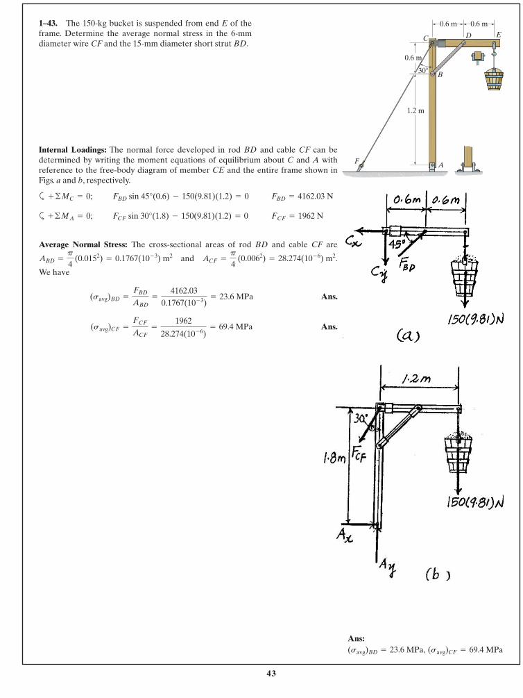
Internal Loadings: The normal force developed in rod BD and cable CF can bedetermined by writing the moment equations of equilibrium about C and A withreference to the free-body diagram of member CE and the entire frame shown inFigs. a and b, respectively.
a
a
Average Normal Stress: The cross-sectional areas of rod BD and cable CF are
and .
We have
Ans.
Ans.(savg)CF =
FCF
ACF=
1962
28.274(10- 6)= 69.4 MPa
(savg)BD =
FBD
ABD=
4162.030.1767(10- 3)
= 23.6 MPa
ACF =
p
4 (0.0062) = 28.274(10- 6) m2ABD =
p
4 (0.0152) = 0.1767(10- 3) m2
FCF = 1962 NFCF sin 30°(1.8) - 150(9.81)(1.2) = 0+ ©MA = 0;
FBD = 4162.03 NFBD sin 45°(0.6) - 150(9.81)(1.2) = 0+ ©MC = 0;
1–43. The 150-kg bucket is suspended from end E of theframe. Determine the average normal stress in the 6-mmdiameter wire CF and the 15-mm diameter short strut BD.
0.6 m0.6 m
1.2 m
D E
F
C
B
A
0.6 m
30�
Ans:(savg)CF = 69.4 MPa(savg)BD = 23.6 MPa,
44
© 2014 Pearson Education, Inc., Upper Saddle River, NJ. All rights reserved. This material is protected under all copyright laws as they currentlyexist. No portion of this material may be reproduced, in any form or by any means, without permission in writing from the publisher.
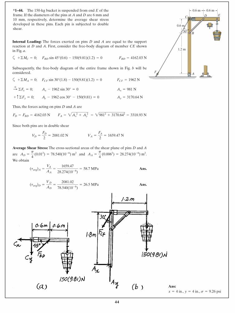
Internal Loading: The forces exerted on pins D and A are equal to the supportreaction at D and A. First, consider the free-body diagram of member CE shown in Fig. a.
a
Subsequently, the free-body diagram of the entire frame shown in Fig. b will beconsidered.
a
Thus, the forces acting on pins D and A are
Since both pins are in double shear
Average Shear Stress: The cross-sectional areas of the shear plane of pins D and A
are and .
We obtain
Ans.
Ans.(tavg)D =
VD
AD=
2081.02
78.540(10- 6)= 26.5 MPa
(tavg)A =
VA
AA=
1659.47
28.274(10- 6)= 58.7 MPa
AA =
p
4 (0.0062) = 28.274(10- 6) m2AD =
p
4 (0.012) = 78.540(10- 6) m2
VA =
FA
2= 1659.47 NVD =
FD
2= 2081.02 N
FA = 2Ax2
+ Ay2 = 29812
+ 3170.642= 3318.93 NFD = FBD = 4162.03 N
Ay = 3170.64 NAy - 1962 cos 30° - 150(9.81) = 0 + c ©Fy = 0;
Ax = 981 NAx - 1962 sin 30° = 0:+ ©Fx = 0;
FCF = 1962 NFCF sin 30°(1.8) - 150(9.81)(1.2) = 0+ ©MA = 0;
FBD = 4162.03 NFBD sin 45°(0.6) - 150(9.81)(1.2) = 0+ ©MC = 0;
*1–44. The 150-kg bucket is suspended from end E of theframe. If the diameters of the pins at A and D are 6 mm and10 mm, respectively, determine the average shear stressdeveloped in these pins. Each pin is subjected to doubleshear.
0.6 m0.6 m
1.2 m
D E
F
C
B
A
0.6 m
30�
Ans:x = 4 in., y = 4 in., s = 9.26 psi
45
© 2014 Pearson Education, Inc., Upper Saddle River, NJ. All rights reserved. This material is protected under all copyright laws as they currentlyexist. No portion of this material may be reproduced, in any form or by any means, without permission in writing from the publisher.
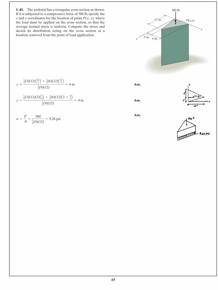
Ans.
Ans.
Ans.s =
P
A=
50012(9)(12)
= 9.26 psi
y =
12(3)(12)(3) A23 B +
12(6)(12) A3 +
63 B
12(9)(12)
= 4 in.
x =
12(3)(12) A12
3 B +12(6)(12) A12
3 B12(9)(12)
= 4 in.
1–45. The pedestal has a triangular cross section as shown.If it is subjected to a compressive force of 500 lb, specify thex and y coordinates for the location of point wherethe load must be applied on the cross section, so that theaverage normal stress is uniform. Compute the stress andsketch its distribution acting on the cross section at alocation removed from the point of load application.
P(x, y),
3 in. 6 in.x
y
500 lb
P(x,y)12 in.
46
© 2014 Pearson Education, Inc., Upper Saddle River, NJ. All rights reserved. This material is protected under all copyright laws as they currentlyexist. No portion of this material may be reproduced, in any form or by any means, without permission in writing from the publisher.
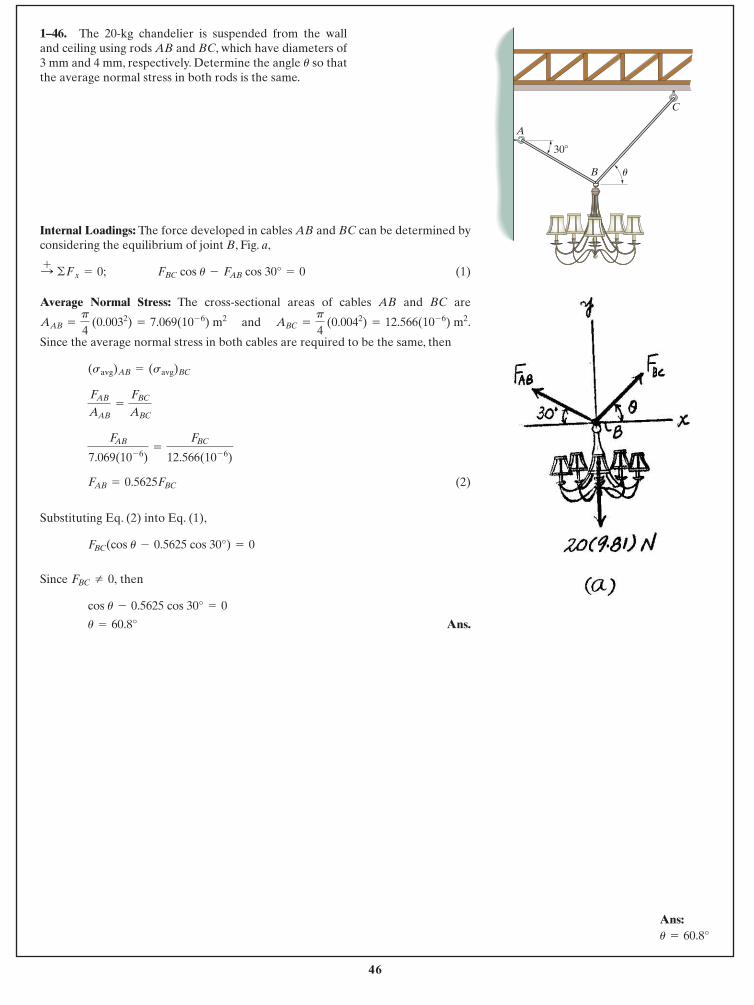
1–46. The 20-kg chandelier is suspended from the walland ceiling using rods AB and BC, which have diameters of 3 mm and 4 mm, respectively. Determine the angle so thatthe average normal stress in both rods is the same.
u
Internal Loadings: The force developed in cables AB and BC can be determined byconsidering the equilibrium of joint B, Fig. a,
(1)
Average Normal Stress: The cross-sectional areas of cables AB and BC are
and .
Since the average normal stress in both cables are required to be the same, then
(2)
Substituting Eq. (2) into Eq. (1),
Since then
Ans.u = 60.8°
cos u - 0.5625 cos 30° = 0
FBC Z 0,
FBC(cos u - 0.5625 cos 30°) = 0
FAB = 0.5625FBC
FAB
7.069(10- 6)=
FBC
12.566(10- 6)
FAB
AAB=
FBC
ABC
(savg)AB = (savg)BC
ABC =
p
4 (0.0042) = 12.566(10- 6) m2AAB =
p
4 (0.0032) = 7.069(10- 6) m2
FBC cos u - FAB cos 30° = 0:+ ©Fx = 0;
B
A
C
30�
u
Ans:u = 60.8°
47
© 2014 Pearson Education, Inc., Upper Saddle River, NJ. All rights reserved. This material is protected under all copyright laws as they currentlyexist. No portion of this material may be reproduced, in any form or by any means, without permission in writing from the publisher.
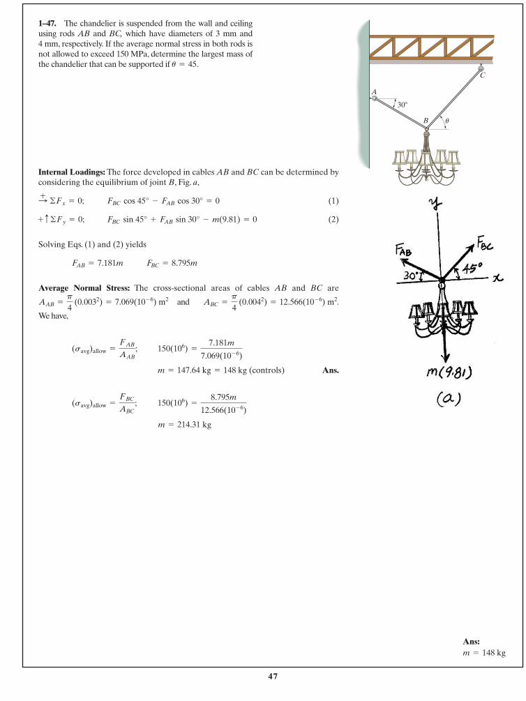
1–47. The chandelier is suspended from the wall and ceilingusing rods AB and BC, which have diameters of 3 mm and 4 mm, respectively. If the average normal stress in both rods isnot allowed to exceed 150 MPa, determine the largest mass ofthe chandelier that can be supported if u = 45.
Internal Loadings: The force developed in cables AB and BC can be determined byconsidering the equilibrium of joint B, Fig. a,
(1)
(2)
Solving Eqs. (1) and (2) yields
Average Normal Stress: The cross-sectional areas of cables AB and BC are
and .
We have,
Ans.
m = 214.31 kg
150(106) =
8.795m
12.566(10- 6)(savg)allow =
FBC
ABC;
m = 147.64 kg = 148 kg (controls)
150(106) =
7.181m
7.069(10- 6)(savg)allow =
FAB
AAB;
ABC =
p
4 (0.0042) = 12.566(10- 6) m2p
4 (0.0032) = 7.069(10- 6) m2AAB =
FBC = 8.795mFAB = 7.181m
FBC sin 45° + FAB sin 30° - m(9.81) = 0 + c ©Fy = 0;
FBC cos 45° - FAB cos 30° = 0:+ ©Fx = 0;
B
A
C
30�
u
Ans:m = 148 kg
48
© 2014 Pearson Education, Inc., Upper Saddle River, NJ. All rights reserved. This material is protected under all copyright laws as they currentlyexist. No portion of this material may be reproduced, in any form or by any means, without permission in writing from the publisher.
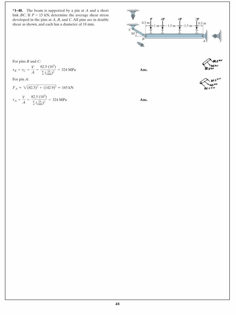
For pins B and C:
Ans.
For pin A:
Ans.tA =
V
A=
82.5 (103)p4 ( 18
1000)2= 324 MPa
FA = 2(82.5)2+ (142.9)2
= 165 kN
tB = tC =
V
A=
82.5 (103)p4 ( 18
1000)2= 324 MPa
*1–48. The beam is supported by a pin at A and a shortlink BC. If P = 15 kN, determine the average shear stressdeveloped in the pins at A, B, and C. All pins are in doubleshear as shown, and each has a diameter of 18 mm.
C
BA
0.5 m1 m 1.5 m 1.5 m
0.5 mP 4P 4P 2P
30�
49
© 2014 Pearson Education, Inc., Upper Saddle River, NJ. All rights reserved. This material is protected under all copyright laws as they currentlyexist. No portion of this material may be reproduced, in any form or by any means, without permission in writing from the publisher.
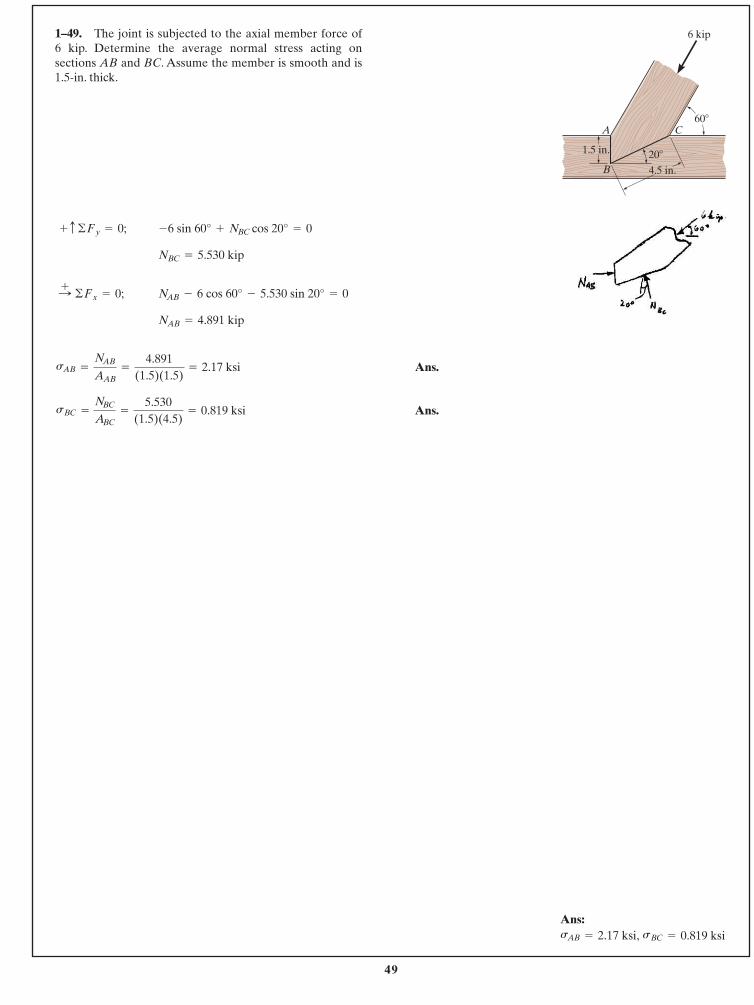
Ans.
Ans.sBC =
NBC
ABC=
5.530(1.5)(4.5)
= 0.819 ksi
sAB =
NAB
AAB=
4.891(1.5)(1.5)
= 2.17 ksi
NAB = 4.891 kip
NAB - 6 cos 60° - 5.530 sin 20° = 0:+ ©Fx = 0;
NBC = 5.530 kip
-6 sin 60° + NBC cos 20° = 0 + c ©Fy = 0;
1–49. The joint is subjected to the axial member force of 6 kip. Determine the average normal stress acting onsections AB and BC. Assume the member is smooth and is1.5-in. thick.
60�
20�
4.5 in.
1.5 in.
A
B
C
6 kip
Ans:sBC = 0.819 ksisAB = 2.17 ksi,
50
© 2014 Pearson Education, Inc., Upper Saddle River, NJ. All rights reserved. This material is protected under all copyright laws as they currentlyexist. No portion of this material may be reproduced, in any form or by any means, without permission in writing from the publisher.
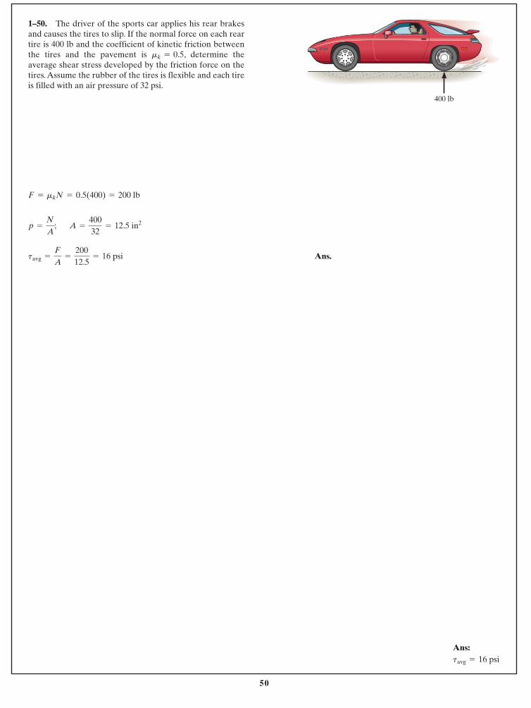
1–50. The driver of the sports car applies his rear brakesand causes the tires to slip. If the normal force on each reartire is 400 lb and the coefficient of kinetic friction betweenthe tires and the pavement is , determine theaverage shear stress developed by the friction force on thetires. Assume the rubber of the tires is flexible and each tireis filled with an air pressure of 32 psi.
mk = 0.5
Ans.tavg =
F
A=
20012.5
= 16 psi
A =
40032
= 12.5 in2p =
N
A;
F = mkN = 0.5(400) = 200 lb
400 lb
Ans:tavg = 16 psi
51
© 2014 Pearson Education, Inc., Upper Saddle River, NJ. All rights reserved. This material is protected under all copyright laws as they currentlyexist. No portion of this material may be reproduced, in any form or by any means, without permission in writing from the publisher.
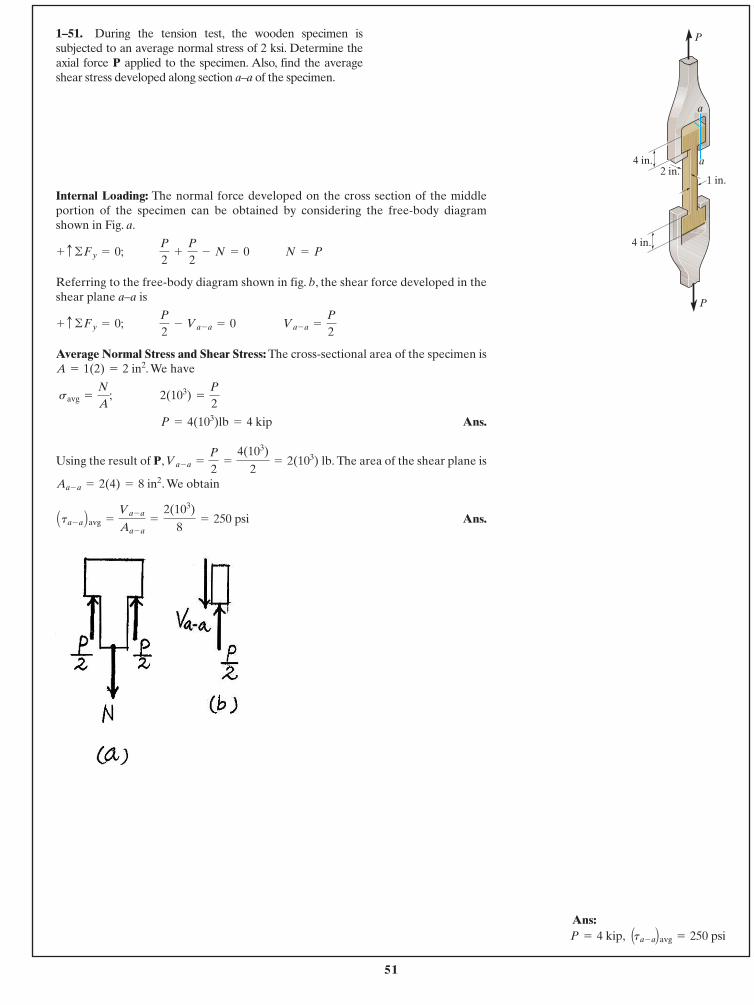
Internal Loading: The normal force developed on the cross section of the middleportion of the specimen can be obtained by considering the free-body diagramshown in Fig. a.
Referring to the free-body diagram shown in fig. b, the shear force developed in theshear plane a–a is
Average Normal Stress and Shear Stress: The cross-sectional area of the specimen is. We have
Ans.
Using the result of P, The area of the shear plane is
. We obtain
Ans.Ata - a Bavg =
Va - a
Aa - a=
2(103)
8= 250 psi
Aa - a = 2(4) = 8 in2
Va - a =
P
2=
4(103)
2= 2(103) lb.
P = 4(103)lb = 4 kip
savg =
N
A; 2(103) =
P
2
A = 1(2) = 2 in2
+ c ©Fy = 0; P
2- Va - a = 0 Va - a =
P
2
+ c ©Fy = 0; P
2+
P
2- N = 0 N = P
1–51. During the tension test, the wooden specimen issubjected to an average normal stress of 2 ksi. Determine theaxial force P applied to the specimen. Also, find the averageshear stress developed along section a–a of the specimen.
P
P
1 in.2 in.
4 in.
4 in.
a
a
Ans: Ata - aBavg = 250 psiP = 4 kip,
52
© 2014 Pearson Education, Inc., Upper Saddle River, NJ. All rights reserved. This material is protected under all copyright laws as they currentlyexist. No portion of this material may be reproduced, in any form or by any means, without permission in writing from the publisher.
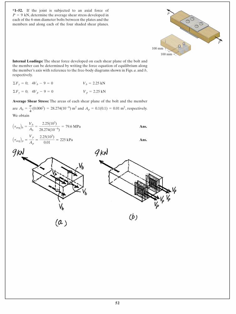
Internal Loadings: The shear force developed on each shear plane of the bolt andthe member can be determined by writing the force equation of equilibrium alongthe member’s axis with reference to the free-body diagrams shown in Figs. a. and b,respectively.
Average Shear Stress: The areas of each shear plane of the bolt and the member
are and , respectively.
We obtain
Ans.
Ans.Atavg Bp =
Vp
Ap=
2.25(103)
0.01= 225 kPa
Atavg Bb =
Vb
Ab=
2.25(103)
28.274(10- 6)= 79.6 MPa
Ap = 0.1(0.1) = 0.01 m2Ab =
p
4 (0.0062) = 28.274(10- 6) m2
©Fy = 0; 4Vp - 9 = 0 Vp = 2.25 kN
©Fy = 0; 4Vb - 9 = 0 Vb = 2.25 kN
*1–52. If the joint is subjected to an axial force of, determine the average shear stress developed in
each of the 6-mm diameter bolts between the plates and themembers and along each of the four shaded shear planes.
P = 9 kN
P
P
100 mm
100 mm
53
© 2014 Pearson Education, Inc., Upper Saddle River, NJ. All rights reserved. This material is protected under all copyright laws as they currentlyexist. No portion of this material may be reproduced, in any form or by any means, without permission in writing from the publisher.
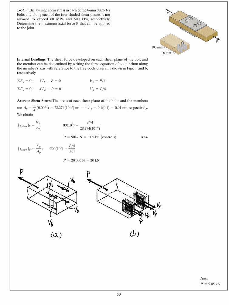
Internal Loadings: The shear force developed on each shear plane of the bolt andthe member can be determined by writing the force equation of equilibrium alongthe member’s axis with reference to the free-body diagrams shown in Figs. a. and b,respectively.
Average Shear Stress: The areas of each shear plane of the bolts and the members
are and , respectively.
We obtain
Ans.
P = 20 000 N = 20 kN
Atallow Bp =
Vp
Ap ; 500(103) =
P>40.01
P = 9047 N = 9.05 kN (controls)
Atallow Bb =
Vb
Ab; 80(106) =
P>428.274(10- 6)
Ap = 0.1(0.1) = 0.01 m2Ab =
p
4 (0.0062) = 28.274(10- 6) m2
©Fy = 0; 4Vp - P = 0 Vp = P>4©Fy = 0; 4Vb - P = 0 Vb = P>4
1–53. The average shear stress in each of the 6-mm diameterbolts and along each of the four shaded shear planes is notallowed to exceed 80 MPa and 500 kPa, respectively.Determine the maximum axial force P that can be appliedto the joint.
P
P
100 mm
100 mm
Ans:
P = 9.05 kN
54
© 2014 Pearson Education, Inc., Upper Saddle River, NJ. All rights reserved. This material is protected under all copyright laws as they currentlyexist. No portion of this material may be reproduced, in any form or by any means, without permission in writing from the publisher.
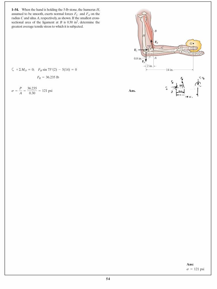
1–54. When the hand is holding the 5-lb stone, the humerus H,assumed to be smooth, exerts normal forces and on theradius C and ulna A, respectively, as shown. If the smallest cross-sectional area of the ligament at B is 0.30 in2, determine thegreatest average tensile stress to which it is subjected.
FAFC
a
Ans.s =
P
A=
36.2350.30
= 121 psi
FB = 36.235 lb
FB sin 75°(2) - 5(14) = 0+ ©MO = 0; 14 in.2 in.
0.8 in.
B
A
CGFB
FC
FA
75�
H
Ans:s = 121 psi
55
© 2014 Pearson Education, Inc., Upper Saddle River, NJ. All rights reserved. This material is protected under all copyright laws as they currentlyexist. No portion of this material may be reproduced, in any form or by any means, without permission in writing from the publisher.
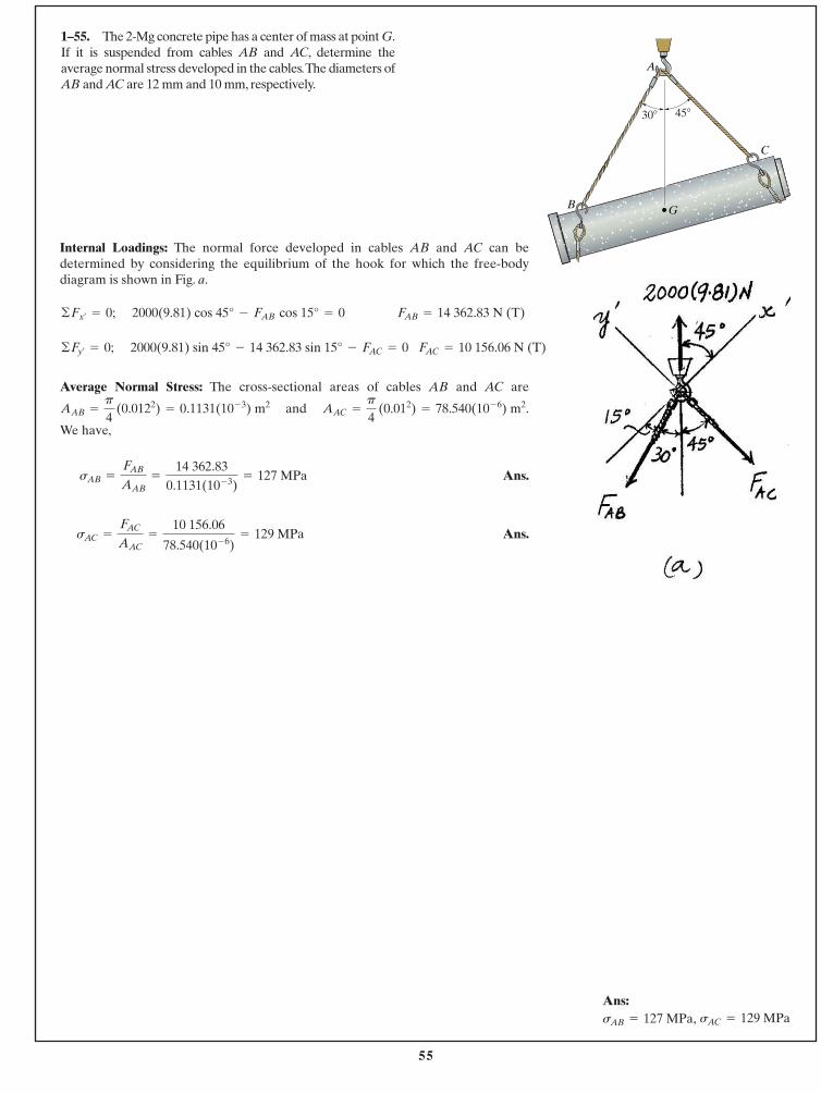
1–55. The 2-Mg concrete pipe has a center of mass at point G.If it is suspended from cables AB and AC, determine theaverage normal stress developed in the cables.The diameters ofAB and AC are 12 mm and 10 mm, respectively.
Internal Loadings: The normal force developed in cables AB and AC can bedetermined by considering the equilibrium of the hook for which the free-bodydiagram is shown in Fig. a.
FAC = 10 156.06 N (T)2000(9.81) sin 45° - 14 362.83 sin 15° - FAC = 0©Fy¿= 0;
FAB = 14 362.83 N (T)2000(9.81) cos 45° - FAB cos 15° = 0©Fx¿= 0;
Average Normal Stress: The cross-sectional areas of cables AB and AC are
and .
We have,
Ans.
Ans.sAC =
FAC
AAC=
10 156.06
78.540(10- 6)= 129 MPa
sAB =
FAB
AAB=
14 362.830.1131(10- 3)
= 127 MPa
AAC =
p
4 (0.012) = 78.540(10- 6) m2AAB =
p
4 (0.0122) = 0.1131(10- 3) m2
A
C
GB
30� 45�
Ans:sAC = 129 MPasAB = 127 MPa,
56
© 2014 Pearson Education, Inc., Upper Saddle River, NJ. All rights reserved. This material is protected under all copyright laws as they currentlyexist. No portion of this material may be reproduced, in any form or by any means, without permission in writing from the publisher.
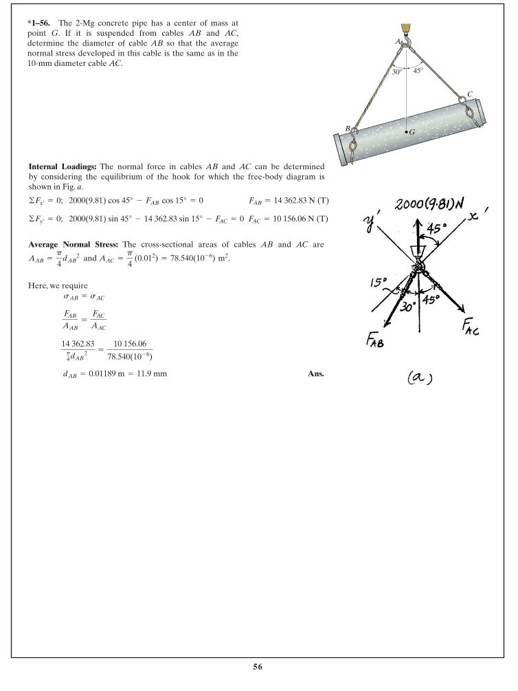
*1–56. The 2-Mg concrete pipe has a center of mass atpoint G. If it is suspended from cables AB and AC,determine the diameter of cable AB so that the averagenormal stress developed in this cable is the same as in the10-mm diameter cable AC.
Internal Loadings: The normal force in cables AB and AC can be determined by considering the equilibrium of the hook for which the free-body diagram isshown in Fig. a.
FAC = 10 156.06 N (T)2000(9.81) sin 45° - 14 362.83 sin 15° - FAC = 0©Fy¿= 0;
FAB = 14 362.83 N (T)2000(9.81) cos 45° - FAB cos 15° = 0©Fx¿= 0;
Average Normal Stress: The cross-sectional areas of cables AB and AC are
and
Here, we require
Ans.dAB = 0.01189 m = 11.9 mm
14 362.83p4dAB 2
=
10 156.06
78.540(10- 6)
FAB
AAB=
FAC
AAC
sAB = sAC
AAC =
p
4 (0.012) = 78.540(10- 6) m2.AAB =
p
4 dAB 2
A
C
GB
30� 45�
57
© 2014 Pearson Education, Inc., Upper Saddle River, NJ. All rights reserved. This material is protected under all copyright laws as they currentlyexist. No portion of this material may be reproduced, in any form or by any means, without permission in writing from the publisher.
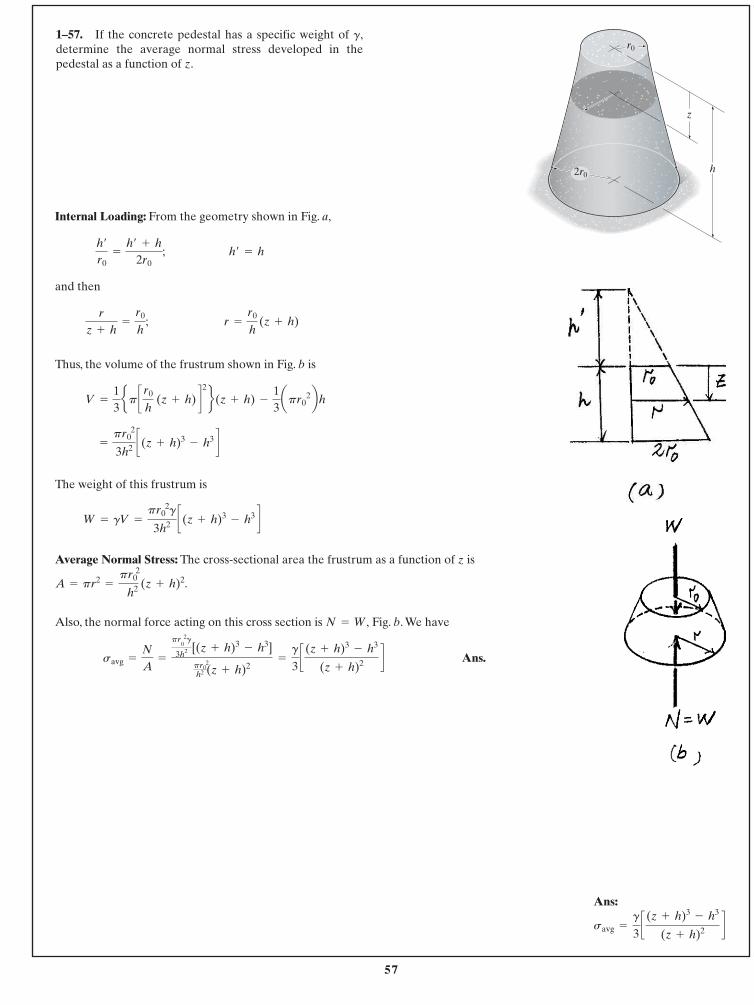
1–57. If the concrete pedestal has a specific weight of g,determine the average normal stress developed in thepedestal as a function of z.
Internal Loading: From the geometry shown in Fig. a,
and then
Thus, the volume of the frustrum shown in Fig. b is
The weight of this frustrum is
Average Normal Stress: The cross-sectional area the frustrum as a function of z is
Also, the normal force acting on this cross section is Fig. b. We have
Ans.=
g
3c (z + h)3
- h3
(z + h)2 dsavg =
N
A=
pr 20g
3h2 [(z + h)3- h3]
pr 20
h2 (z + h)2
N = W,
A = pr2=
pr 20
h2 (z + h)2.
W = gV =
pr0 2g
3h2 c(z + h)3- h3 d
=
pr0 2
3h2 c(z + h)3- h3 d
V =
13ep c r0
h (z + h) d2 f(z + h) -
13apr0
2bh
r =
r0
h (z + h)
r
z + h=
r0
h;
h¿ = hh¿
r0=
h¿ + h
2r0;
r0
2r0h
z
Ans:
savg =
g
3c (z + h)3
- h3
(z + h)2 d
58
© 2014 Pearson Education, Inc., Upper Saddle River, NJ. All rights reserved. This material is protected under all copyright laws as they currentlyexist. No portion of this material may be reproduced, in any form or by any means, without permission in writing from the publisher.
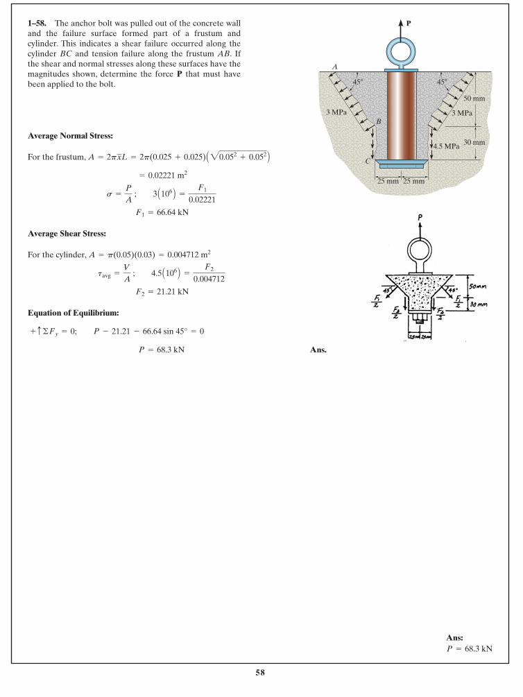
Average Normal Stress:
For the frustum,
Average Shear Stress:
For the cylinder,
Equation of Equilibrium:
Ans. P = 68.3 kN
+ c ©Fy = 0; P - 21.21 - 66.64 sin 45° = 0
F2 = 21.21 kN
tavg =
V
A ; 4.5 A106 B =
F2
0.004712
A = p(0.05)(0.03) = 0.004712 m2
F1 = 66.64 kN
s =
P
A ; 3 A106 B =
F1
0.02221
= 0.02221 m2
A = 2pxL = 2p(0.025 + 0.025) A20.052+ 0.052 B
1–58. The anchor bolt was pulled out of the concrete walland the failure surface formed part of a frustum andcylinder. This indicates a shear failure occurred along thecylinder BC and tension failure along the frustum AB. Ifthe shear and normal stresses along these surfaces have themagnitudes shown, determine the force P that must havebeen applied to the bolt.
30 mm4.5 MPa
3 MPa 3 MPa
P
50 mm
A
25 mm 25 mm
B
C
45�45�
Ans: P = 68.3 kN
59
© 2014 Pearson Education, Inc., Upper Saddle River, NJ. All rights reserved. This material is protected under all copyright laws as they currentlyexist. No portion of this material may be reproduced, in any form or by any means, without permission in writing from the publisher.
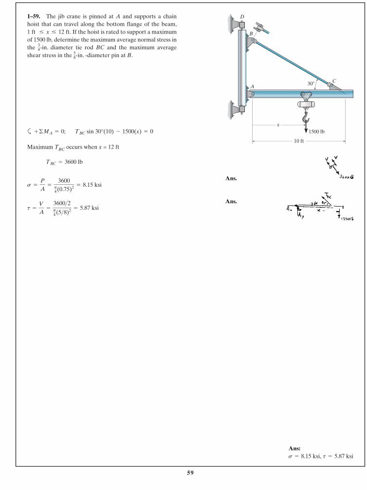
1–59. The jib crane is pinned at A and supports a chainhoist that can travel along the bottom flange of the beam,
If the hoist is rated to support a maximumof 1500 lb, determine the maximum average normal stress inthe -in. diameter tie rod BC and the maximum averageshear stress in the -in. -diameter pin at B.5
8
34
1 ft … x … 12 ft.
a
Maximum TBC occurs when x = 12 ft
Ans.
Ans.t =
V
A=
3600>2p4(5>8)2 = 5.87 ksi
s =
P
A=
3600p4(0.75)2 = 8.15 ksi
TBC = 3600 lb
TBC sin 30°(10) - 1500(x) = 0+ ©MA = 0;
C
10 ft
x
A
B
30�
D
1500 lb
Ans:t = 5.87 ksis = 8.15 ksi,
60
© 2014 Pearson Education, Inc., Upper Saddle River, NJ. All rights reserved. This material is protected under all copyright laws as they currentlyexist. No portion of this material may be reproduced, in any form or by any means, without permission in writing from the publisher.
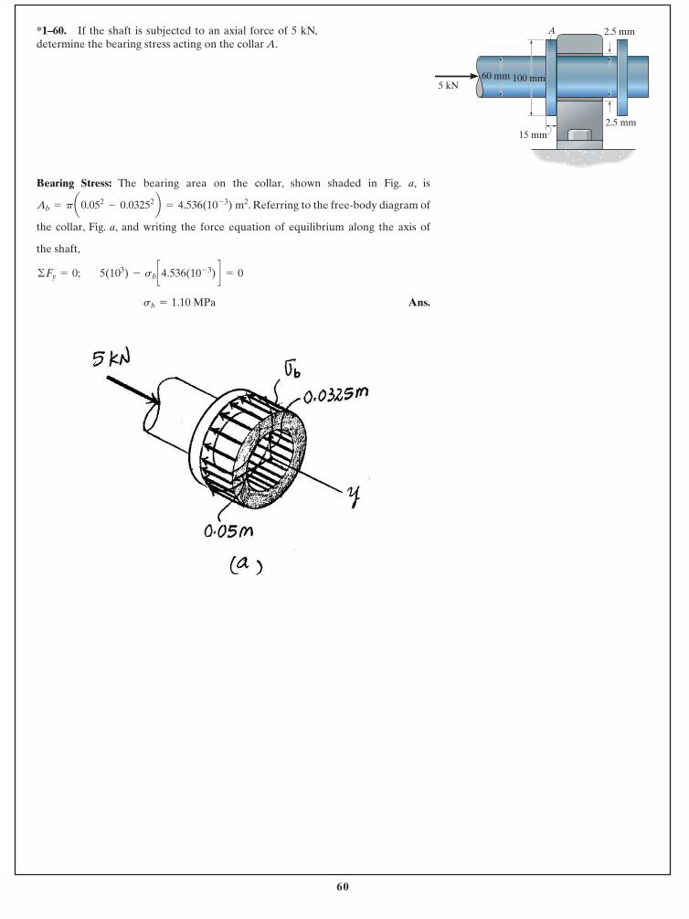
*1–60. If the shaft is subjected to an axial force of 5 kN,determine the bearing stress acting on the collar A.
Bearing Stress: The bearing area on the collar, shown shaded in Fig. a, is
. Referring to the free-body diagram of
the collar, Fig. a, and writing the force equation of equilibrium along the axis of
the shaft,
Ans.sb = 1.10 MPa
5(103) - sb c4.536(10- 3) d = 0©Fy = 0;
Ab = pa0.052- 0.03252b = 4.536(10- 3) m2
A 2.5 mm
2.5 mm
100 mm60 mm5 kN
15 mm
61
© 2014 Pearson Education, Inc., Upper Saddle River, NJ. All rights reserved. This material is protected under all copyright laws as they currentlyexist. No portion of this material may be reproduced, in any form or by any means, without permission in writing from the publisher.
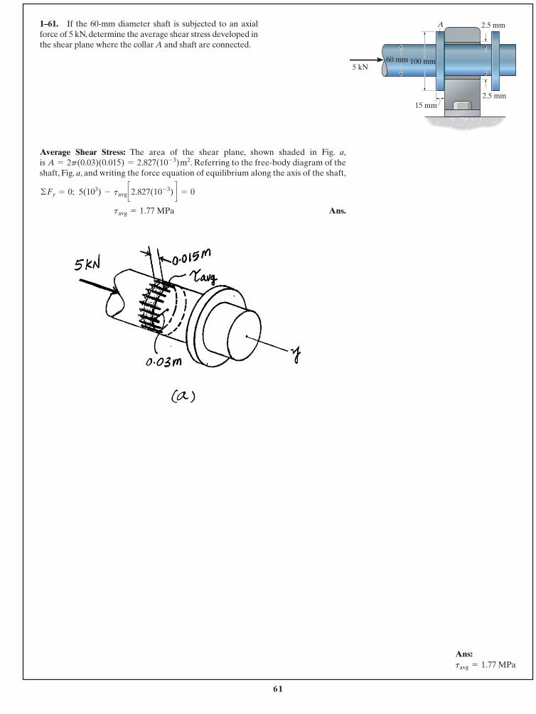
1–61. If the 60-mm diameter shaft is subjected to an axialforce of 5 kN, determine the average shear stress developed inthe shear plane where the collar A and shaft are connected.
Average Shear Stress: The area of the shear plane, shown shaded in Fig. a,is . Referring to the free-body diagram of theshaft, Fig. a, and writing the force equation of equilibrium along the axis of the shaft,
Ans.tavg = 1.77 MPa
5(103) - tavg c2.827(10- 3) d = 0©Fy = 0;
A = 2p(0.03)(0.015) = 2.827(10- 3) m2
A 2.5 mm
2.5 mm
100 mm60 mm5 kN
15 mm
Ans:tavg = 1.77 MPa
62
© 2014 Pearson Education, Inc., Upper Saddle River, NJ. All rights reserved. This material is protected under all copyright laws as they currentlyexist. No portion of this material may be reproduced, in any form or by any means, without permission in writing from the publisher.
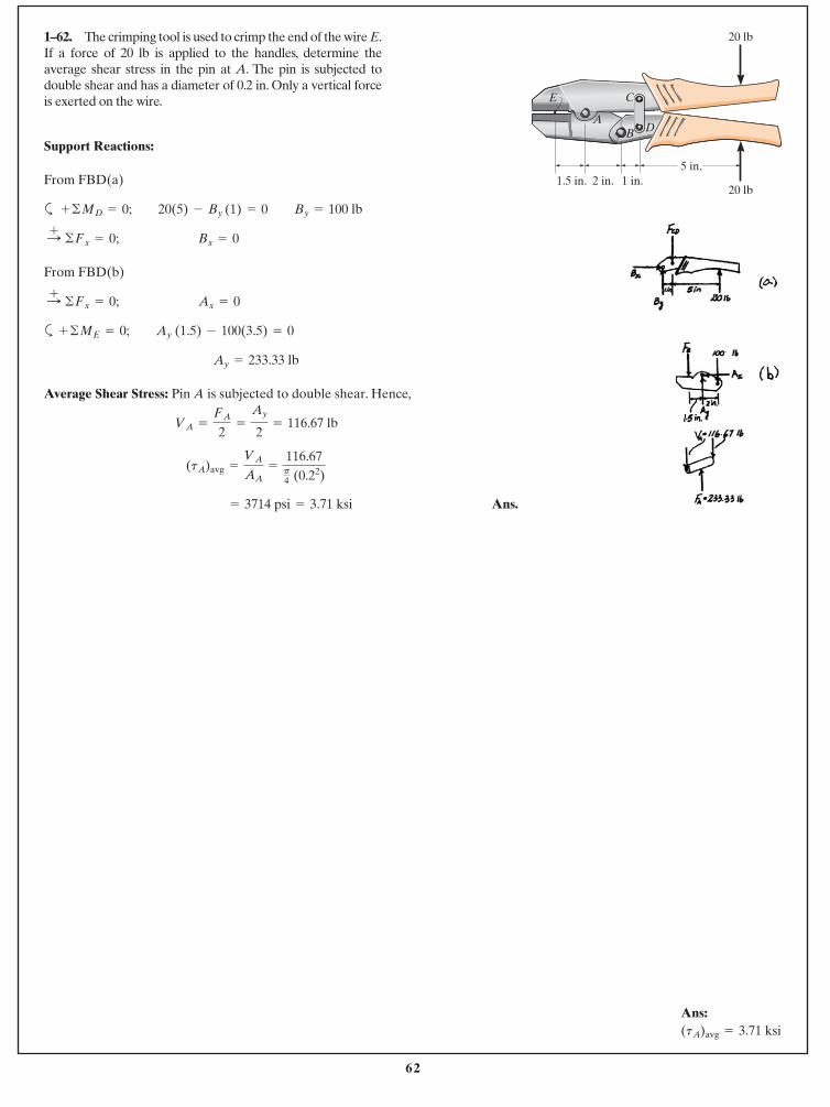
Support Reactions:
From FBD(a)
a
From FBD(b)
a
Average Shear Stress: Pin A is subjected to double shear. Hence,
Ans. = 3714 psi = 3.71 ksi
(tA)avg =
VA
AA=
116.67p4 (0.22)
VA =
FA
2=
Ay
2= 116.67 lb
Ay = 233.33 lb
+ ©ME = 0; Ay (1.5) - 100(3.5) = 0
:+ ©Fx = 0; Ax = 0
:+ ©Fx = 0; Bx = 0
+ ©MD = 0; 20(5) - By (1) = 0 By = 100 lb
1–62. The crimping tool is used to crimp the end of the wire E.If a force of 20 lb is applied to the handles, determine theaverage shear stress in the pin at A. The pin is subjected todouble shear and has a diameter of 0.2 in. Only a vertical forceis exerted on the wire.
A
20 lb
20 lb
5 in.1.5 in. 2 in. 1 in.
E C
B D
Ans:(tA)avg = 3.71 ksi
63
© 2014 Pearson Education, Inc., Upper Saddle River, NJ. All rights reserved. This material is protected under all copyright laws as they currentlyexist. No portion of this material may be reproduced, in any form or by any means, without permission in writing from the publisher.
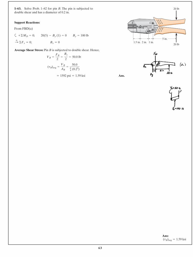
Support Reactions:
From FBD(a)
a
Average Shear Stress: Pin B is subjected to double shear. Hence,
Ans. = 1592 psi = 1.59 ksi
(tB)avg =
VB
AB=
50.0p4 (0.22)
VB =
FB
2=
By
2= 50.0 lb
:+ ©Fx = 0; Bx = 0
+ ©MD = 0; 20(5) - By (1) = 0 By = 100 lb
1–63. Solve Prob. 1–62 for pin B. The pin is subjected todouble shear and has a diameter of 0.2 in.
A
20 lb
20 lb
5 in.1.5 in. 2 in. 1 in.
E C
B D
Ans: (tB)avg = 1.59 ksi
64
© 2014 Pearson Education, Inc., Upper Saddle River, NJ. All rights reserved. This material is protected under all copyright laws as they currentlyexist. No portion of this material may be reproduced, in any form or by any means, without permission in writing from the publisher.
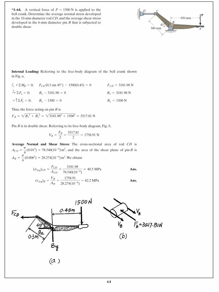
*1–64. A vertical force of is applied to thebell crank. Determine the average normal stress developedin the 10-mm diameter rod CD, and the average shear stressdeveloped in the 6-mm diameter pin B that is subjected todouble shear.
P = 1500 N
Internal Loading: Referring to the free-body diagram of the bell crank shown in Fig. a,
a
Thus, the force acting on pin B is
Pin B is in double shear. Referring to its free-body diagram, Fig. b,
Average Normal and Shear Stress: The cross-sectional area of rod CD is
, and the area of the shear plane of pin B is
. We obtain
Ans.
Ans.(tavg)B =
VB
AB=
1758.91
28.274(10- 6)= 62.2 MPa
(savg)CD =
FCD
ACD=
3181.98
78.540(10- 6)= 40.5 MPa
AB =
p
4 (0.0062) = 28.274(10- 6) m2
ACD =
p
4 (0.012) = 78.540(10- 6) m2
VB =
FB
2=
3517.812
= 1758.91 N
= 3517.81 NFB = 2Bx2
+ By2
= 23181.982+ 15002
By = 1500 NBy - 1500 = 0 + c ©Fy = 0;
Bx = 3181.98 NBx - 3181.98 = 0 :+ ©Fx = 0;
FCD = 3181.98 NFCD (0.3 sin 45°) - 1500(0.45) = 0 + ©MB = 0;
450 mm
300 mm45�
P
A
B
CD
65
© 2014 Pearson Education, Inc., Upper Saddle River, NJ. All rights reserved. This material is protected under all copyright laws as they currentlyexist. No portion of this material may be reproduced, in any form or by any means, without permission in writing from the publisher.
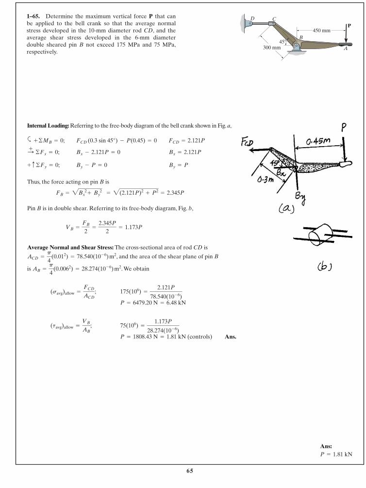
1–65. Determine the maximum vertical force P that canbe applied to the bell crank so that the average normalstress developed in the 10-mm diameter rod CD, and theaverage shear stress developed in the 6-mm diameterdouble sheared pin B not exceed 175 MPa and 75 MPa,respectively.
Internal Loading: Referring to the free-body diagram of the bell crank shown in Fig. a,
a
Thus, the force acting on pin B is
Pin B is in double shear. Referring to its free-body diagram, Fig. b,
Average Normal and Shear Stress: The cross-sectional area of rod CD is
, and the area of the shear plane of pin B
is . We obtain
Ans.P = 1808.43 N = 1.81 kN (controls)
75(106) =
1.173P
28.274(10- 6)(tavg)allow =
VB
AB;
P = 6479.20 N = 6.48 kN
175(106) =
2.121P
78.540(10- 6)(savg)allow =
FCD
ACD;
AB =
p
4(0.0062) = 28.274(10- 6) m2
ACD =
p
4(0.012) = 78.540(10- 6) m2
VB =
FB
2=
2.345P
2= 1.173P
FB = 2B 2x + B 2
y = 2(2.121P)2+ P2
= 2.345P
By = PBy - P = 0+ c ©Fy = 0;
Bx = 2.121PBx - 2.121P = 0 :+ ©Fx = 0;
FCD = 2.121PFCD (0.3 sin 45°) - P(0.45) = 0 + ©MB = 0;
450 mm
300 mm45�
P
A
B
CD
Ans:P = 1.81 kN
66
© 2014 Pearson Education, Inc., Upper Saddle River, NJ. All rights reserved. This material is protected under all copyright laws as they currentlyexist. No portion of this material may be reproduced, in any form or by any means, without permission in writing from the publisher.
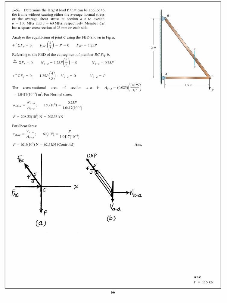
Analyze the equilibrium of joint C using the FBD Shown in Fig. a,
Referring to the FBD of the cut segment of member BC Fig. b.
The cross-sectional area of section a–a is
. For Normal stress,
For Shear Stress
Ans. P = 62.5(103) N = 62.5 kN (Controls!)
tallow =
Va - a
Aa - a ; 60(106) =
P
1.0417(10- 3)
P = 208.33(103) N = 208.33 kN
sallow =
Na - a
Aa - a ; 150(106) =
0.75P
1.0417(10- 3)
= 1.0417(10- 3) m2
Aa - a = (0.025)a0.0253>5 b
+ c ©Fy = 0; 1.25Pa 45b - Va - a = 0 Va - a = P
:+ ©Fx = 0; Na - a - 1.25Pa35b = 0 Na - a = 0.75P
+ c ©Fy = 0; FBC a 45b - P = 0 FBC = 1.25P
1–66. Determine the largest load P that can be applied tothe frame without causing either the average normal stressor the average shear stress at section a–a to exceed
and , respectively. Member CBhas a square cross section of 25 mm on each side.
t = 60 MPas = 150 MPa
2 m
B
AC
1.5 m
a
a
P
Ans:P = 62.5 kN
67
© 2014 Pearson Education, Inc., Upper Saddle River, NJ. All rights reserved. This material is protected under all copyright laws as they currentlyexist. No portion of this material may be reproduced, in any form or by any means, without permission in writing from the publisher.
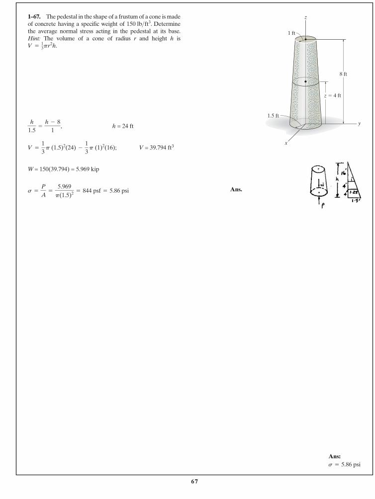
1–67. The pedestal in the shape of a frustum of a cone is madeof concrete having a specific weight of . Determinethe average normal stress acting in the pedestal at its base.Hint: The volume of a cone of radius r and height h isV =
13pr2h.
150 lb>ft3
h = 24 ft
V = 39.794 ft3
W = 150(39.794) = 5.969 kip
Ans.s =
P
A=
5.969p(1.5)2 = 844 psf = 5.86 psi
V =
13
p (1.5)2(24) -
13
p (1)2(16);
h
1.5=
h - 81
,
z
y
x
8 ft
z � 4 ft
1 ft
1.5 ft
Ans:s = 5.86 psi
68
© 2014 Pearson Education, Inc., Upper Saddle River, NJ. All rights reserved. This material is protected under all copyright laws as they currentlyexist. No portion of this material may be reproduced, in any form or by any means, without permission in writing from the publisher.
*1–68. The pedestal in the shape of a frustum of a cone ismade of concrete having a specific weight of .Determine the average normal stress acting in the pedestalat its midheight, Hint: The volume of a cone of
radius r and height h is V =13pr2h.
z = 4 ft.
150 lb>ft3
Ans.s =
P
A=
2395.5p(1.25)2 = 488 psf = 3.39 psi
P = 2395.5 lb
+ c gFy = 0; P - 2395.5 = 0
W = c13
p (1.25)2 20 -
13
(p) (12)(16) d(150) = 2395.5 lb
h = 24 fth
1.5=
h - 81
,
z
y
x
8 ft
z � 4 ft
1 ft
1.5 ft
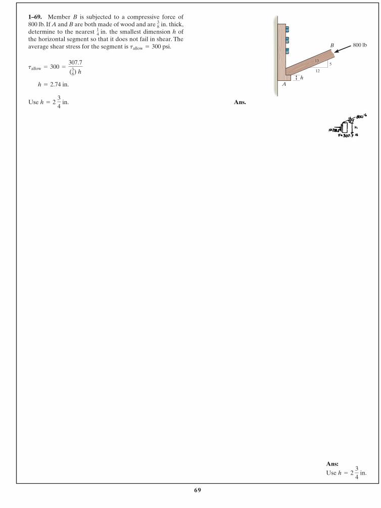
69
© 2014 Pearson Education, Inc., Upper Saddle River, NJ. All rights reserved. This material is protected under all copyright laws as they currentlyexist. No portion of this material may be reproduced, in any form or by any means, without permission in writing from the publisher.
800 lbB
hA
12
513
Ans.Use h = 2 34
in.
h = 2.74 in.
tallow = 300 =
307.7
(38) h
1–69. Member B is subjected to a compressive force of800 lb. If A and B are both made of wood and are thick,determine to the nearest the smallest dimension h ofthe horizontal segment so that it does not fail in shear. Theaverage shear stress for the segment is tallow = 300 psi.
14 in.
38 in.
Ans:Use h = 2
34
in.
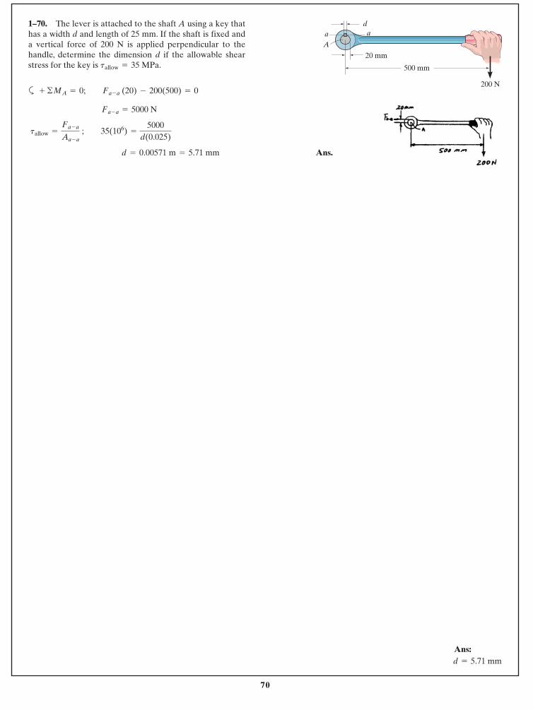
70
© 2014 Pearson Education, Inc., Upper Saddle River, NJ. All rights reserved. This material is protected under all copyright laws as they currentlyexist. No portion of this material may be reproduced, in any form or by any means, without permission in writing from the publisher.
500 mm
20 mm
daa
A
200 Na
Ans. d = 0.00571 m = 5.71 mm
tallow =
Fa - a
Aa - a ; 35(106) =
5000d(0.025)
Fa - a = 5000 N
+ ©MA = 0; Fa - a (20) - 200(500) = 0
1–70. The lever is attached to the shaft A using a key thathas a width d and length of 25 mm. If the shaft is fixed anda vertical force of 200 N is applied perpendicular to thehandle, determine the dimension d if the allowable shearstress for the key is tallow = 35 MPa.
Ans:d = 5.71 mm
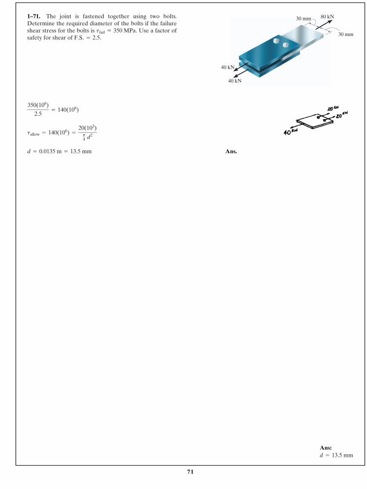
71
© 2014 Pearson Education, Inc., Upper Saddle River, NJ. All rights reserved. This material is protected under all copyright laws as they currentlyexist. No portion of this material may be reproduced, in any form or by any means, without permission in writing from the publisher.
Ans.d = 0.0135 m = 13.5 mm
tallow = 140(106) =
20(103)p4 d2
350(106)
2.5= 140(106)
1–71. The joint is fastened together using two bolts.Determine the required diameter of the bolts if the failureshear stress for the bolts is Use a factor ofsafety for shear of F.S. = 2.5.
tfail = 350 MPa.
80 kN
40 kN
30 mm
30 mm
40 kN
Ans:d = 13.5 mm
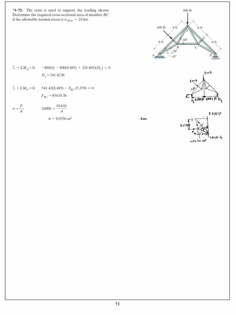
72
© 2014 Pearson Education, Inc., Upper Saddle River, NJ. All rights reserved. This material is protected under all copyright laws as they currentlyexist. No portion of this material may be reproduced, in any form or by any means, without permission in writing from the publisher.
a MA = 0; -400(6) - 800(8.485) + 2(8.485)(Dy) = 0
Dy = 541.42 lb
a MF = 0; 541.42(8.485) - FBC (5.379) = 0
FBC = 854.01 lb
= 24000 =
A = 0.0356 in2 Ans.
854.01A
P
A;s
+ ©
+ ©
*1–72. The truss is used to support the loading shownDetermine the required cross-sectional area of member BCif the allowable normal stress is .sallow = 24 ksi
800 lb
E
C
F400 lb
D
6 ft 6 ft
6 ft 6 ft
45�
30�
60�
B
A
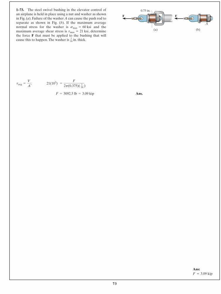
73
© 2014 Pearson Education, Inc., Upper Saddle River, NJ. All rights reserved. This material is protected under all copyright laws as they currentlyexist. No portion of this material may be reproduced, in any form or by any means, without permission in writing from the publisher.
Ans.F = 3092.5 lb = 3.09 kip
21(103) =
F
2p(0.375)( 116 )
tavg =
V
A;
1–73. The steel swivel bushing in the elevator control of an airplane is held in place using a nut and washer as shownin Fig. (a). Failure of the washer A can cause the push rod toseparate as shown in Fig. (b). If the maximum averagenormal stress for the washer is and themaximum average shear stress is , determinethe force F that must be applied to the bushing that willcause this to happen. The washer is in. thick.1
16
tmax = 21 ksismax = 60 ksi
(a) (b)
A
0.75 in.
FF
Ans:F = 3.09 kip
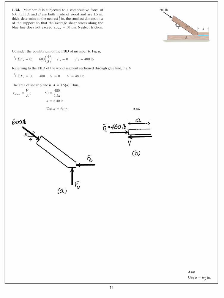
74
© 2014 Pearson Education, Inc., Upper Saddle River, NJ. All rights reserved. This material is protected under all copyright laws as they currentlyexist. No portion of this material may be reproduced, in any form or by any means, without permission in writing from the publisher.
Consider the equilibrium of the FBD of member B, Fig. a,
Referring to the FBD of the wood segment sectioned through glue line, Fig. b
The area of shear plane is . Thus,
Ans. Use a = 612 in.
a = 6.40 in.
tallow =
V
A ; 50 =
4801.5a
A = 1.5(a)
:+ ©Fx = 0; 480 - V = 0 V = 480 lb
:+ ©Fx = 0; 600a 45b - Fh = 0 Fh = 480 lb
1–74. Member B is subjected to a compressive force of600 lb. If A and B are both made of wood and are 1.5 in.thick, determine to the nearest the smallest dimension aof the support so that the average shear stress along theblue line does not exceed . Neglect friction.tallow = 50 psi
18 in.
600 lb
a
A
B4
53
Ans:
Use a = 612
in.
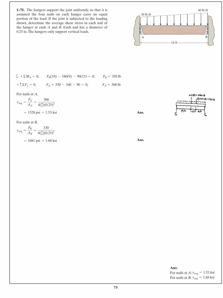
75
© 2014 Pearson Education, Inc., Upper Saddle River, NJ. All rights reserved. This material is protected under all copyright laws as they currentlyexist. No portion of this material may be reproduced, in any form or by any means, without permission in writing from the publisher.
1–75. The hangers support the joist uniformly, so that it isassumed the four nails on each hanger carry an equalportion of the load. If the joist is subjected to the loadingshown, determine the average shear stress in each nail ofthe hanger at ends A and B. Each nail has a diameter of 0.25 in. The hangers only support vertical loads.
a
For nails at A,
Ans.
For nails at B,
Ans.= 1681 psi = 1.68 ksi
tavg =
FB
AB=
3304(p4)(0.25)2
= 1528 psi = 1.53 ksi
tavg =
FA
AA=
3004(p4)(0.25)2
FA = 300 lbFA + 330 - 540 - 90 = 0; + c ©Fy = 0;
FB = 330 lbFB(18) - 540(9) - 90(12) = 0;+ ©MA = 0;
18 ft
A B
30 lb/ft40 lb/ft
Ans:For nails at A:For nails at B: tavg = 1.68 ksi
tavg = 1.53 ksi
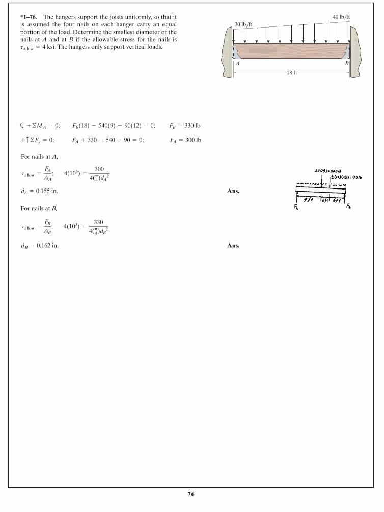
76
© 2014 Pearson Education, Inc., Upper Saddle River, NJ. All rights reserved. This material is protected under all copyright laws as they currentlyexist. No portion of this material may be reproduced, in any form or by any means, without permission in writing from the publisher.
*1–76. The hangers support the joists uniformly, so that itis assumed the four nails on each hanger carry an equalportion of the load. Determine the smallest diameter of thenails at A and at B if the allowable stress for the nails is
. The hangers only support vertical loads.tallow = 4 ksi
a
For nails at A,
Ans.
For nails at B,
Ans.dB = 0.162 in.
4(103) =
3304(p4)dB 2
tallow =
FB
AB;
dA = 0.155 in.
4(103) =
3004(p4)dA 2
tallow =
FA
AA;
FA = 300 lbFA + 330 - 540 - 90 = 0; + c ©Fy = 0;
FB = 330 lbFB(18) - 540(9) - 90(12) = 0;+ ©MA = 0;
18 ft
A B
30 lb/ft40 lb/ft
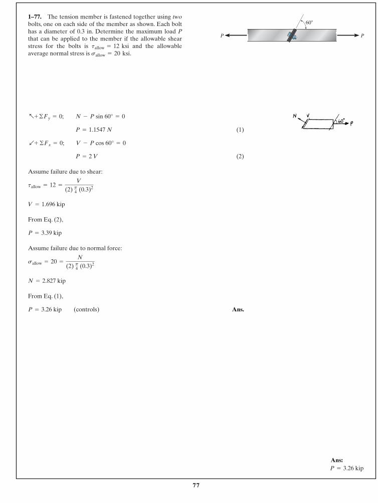
77
© 2014 Pearson Education, Inc., Upper Saddle River, NJ. All rights reserved. This material is protected under all copyright laws as they currentlyexist. No portion of this material may be reproduced, in any form or by any means, without permission in writing from the publisher.
(1)
(2)
Assume failure due to shear:
From Eq. (2),
Assume failure due to normal force:
From Eq. (1),
Ans.P = 3.26 kip (controls)
N = 2.827 kip
sallow = 20 =
N
(2) p4 (0.3)2
P = 3.39 kip
V = 1.696 kip
tallow = 12 =
V
(2) p4 (0.3)2
P = 2 V
b+ ©Fx = 0; V - P cos 60° = 0
P = 1.1547 N
a+ ©Fy = 0; N - P sin 60° = 0
1–77. The tension member is fastened together using twobolts, one on each side of the member as shown. Each bolthas a diameter of 0.3 in. Determine the maximum load Pthat can be applied to the member if the allowable shearstress for the bolts is and the allowableaverage normal stress is .sallow = 20 ksi
tallow = 12 ksi
60�
PP
Ans:P = 3.26 kip
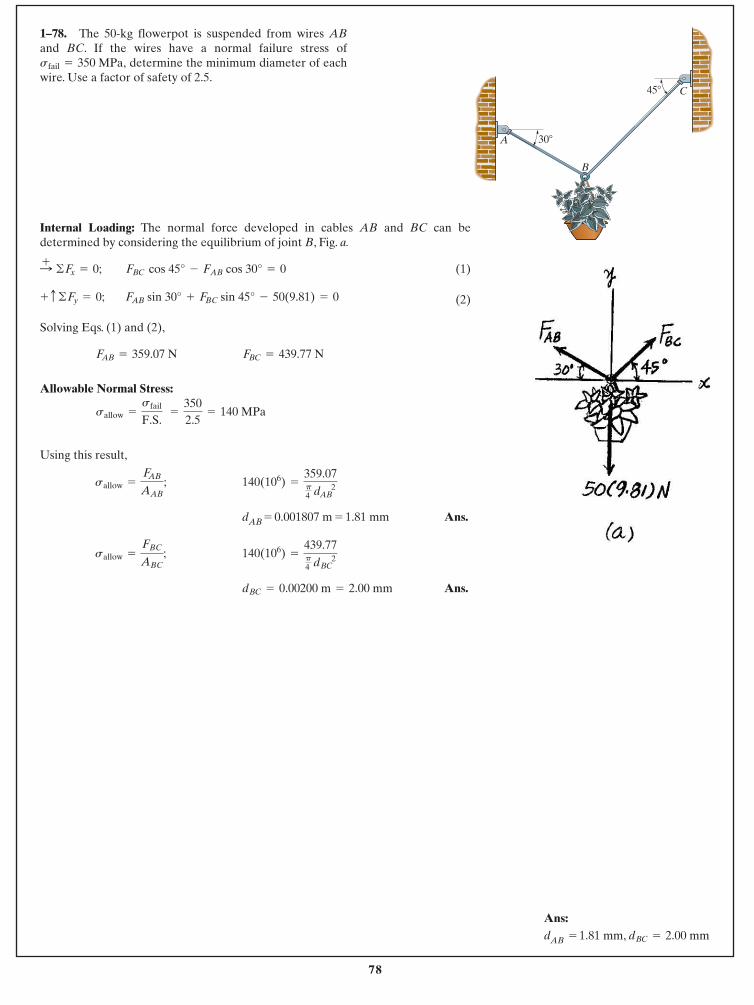
78
© 2014 Pearson Education, Inc., Upper Saddle River, NJ. All rights reserved. This material is protected under all copyright laws as they currentlyexist. No portion of this material may be reproduced, in any form or by any means, without permission in writing from the publisher.
1–78. The 50-kg flowerpot is suspended from wires ABand BC. If the wires have a normal failure stress of
determine the minimum diameter of eachwire. Use a factor of safety of 2.5.sfail = 350 MPa,
Internal Loading: The normal force developed in cables AB and BC can bedetermined by considering the equilibrium of joint B, Fig. a.
(1)
(2)
Solving Eqs. (1) and (2),
Allowable Normal Stress:
Using this result,
dAB = 0.001807 m = 1.81 mm Ans.
Ans.dBC = 0.00200 m = 2.00 mm
140(106) =
439.77p4 dBC 2
sallow =
FBC
ABC;
140(106) =
359.07p4 dAB 2
sallow =
FAB
AAB;
sallow =
sfail
F.S. =
3502.5
= 140 MPa
FBC = 439.77 NFAB = 359.07 N
FAB sin 30° + FBC sin 45° - 50(9.81) = 0 + c ©Fy = 0;
FBC cos 45° - FAB cos 30° = 0 :+ ©Fx = 0;
A
B
C
30�
45�
Ans:dAB = 1.81 mm, dBC = 2.00 mm
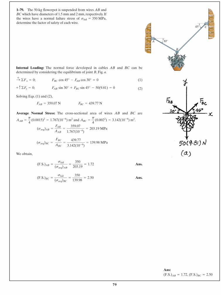
79
© 2014 Pearson Education, Inc., Upper Saddle River, NJ. All rights reserved. This material is protected under all copyright laws as they currentlyexist. No portion of this material may be reproduced, in any form or by any means, without permission in writing from the publisher.
1–79. The 50-kg flowerpot is suspended from wires AB andBC which have diameters of 1.5 mm and 2 mm, respectively. Ifthe wires have a normal failure stress of determine the factor of safety of each wire.
sfail = 350 MPa,
Internal Loading: The normal force developed in cables AB and BC can bedetermined by considering the equilibrium of joint B, Fig. a.
(1)
(2)
Solving Eqs. (1) and (2),
Average Normal Stress: The cross-sectional area of wires AB and BC are
and .
We obtain,
Ans.
Ans.(F.S.)BC =
sfail
(savg)BC=
350139.98
= 2.50
(F.S.)AB =
sfail
(savg)AB=
350203.19
= 1.72
(savg)BC = FBC
ABC=
439.77
3.142(10- 6)= 139.98 MPa
(savg)AB =
FAB
AAB=
359.07
1.767(10- 6)= 203.19 MPa
ABC =
p
4 (0.0022) = 3.142(10- 6) m2AAB =
p
4 (0.0015)2
= 1.767(10- 6) m2
FBC = 439.77 NFAB = 359.07 N
FAB sin 30° + FBC sin 45° - 50(9.81) = 0 + c ©Fy = 0;
FBC cos 45° - FAB cos 30° = 0 :+ ©Fx = 0;
A
B
C
30�
45�
Ans:(F.S.)BC = 2.50(F.S.)AB = 1.72,
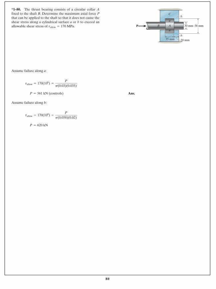
80
© 2014 Pearson Education, Inc., Upper Saddle River, NJ. All rights reserved. This material is protected under all copyright laws as they currentlyexist. No portion of this material may be reproduced, in any form or by any means, without permission in writing from the publisher.
*1–80. The thrust bearing consists of a circular collar Afixed to the shaft B. Determine the maximum axial force Pthat can be applied to the shaft so that it does not cause theshear stress along a cylindrical surface a or b to exceed anallowable shear stress of MPa.tallow = 170
Assume failure along a:
Ans.
Assume failure along b:
P = 620 kN
tallow = 170(106) =
Pp(0.058)(0.02)
P = 561 kN (controls)
tallow = 170(106) =
Pp(0.03)(0.035)
20 mm
30 mm 58 mm
b
b35 mm
B A
C
a
aP
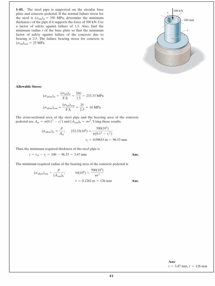
81
© 2014 Pearson Education, Inc., Upper Saddle River, NJ. All rights reserved. This material is protected under all copyright laws as they currentlyexist. No portion of this material may be reproduced, in any form or by any means, without permission in writing from the publisher.
1–81. The steel pipe is supported on the circular baseplate and concrete pedestal. If the normal failure stress forthe steel is MPa, determine the minimumthickness t of the pipe if it supports the force of 500 kN. Usea factor of safety against failure of 1.5. Also, find theminimum radius r of the base plate so that the minimumfactor of safety against failure of the concrete due tobearing is 2.5. The failure bearing stress for concrete is(sfail)con = 25 MPa.
(sfail)st = 350
Allowable Stress:
The cross-sectional area of the steel pipe and the heaving area of the concretepedestal are and Using these results,
Thus, the minimum required thickness of the steel pipe is
Ans.
The minimum required radius of the bearing area of the concrete pedestal is
Ans.r = 0.1262 m = 126 mm
10(106) =
500(103)
pr2(sallow)con =
P
(Acon)b;
t = rO - ri = 100 - 96.53 = 3.47 mm
ri = 0.09653 m = 96.53 mm
233.33(106) =
500(103)
p(0.12- ri
2 )(sallow)st =
P
Ast;
(Acon)b = pr2.Ast = p(0.12- ri
2)
(sallow)con =
(sfail)con
F.S.=
252.5
= 10 MPa
(sallow)st =
(sfail)st
F.S.=
3501.5
= 233.33 MPa
r
t
100 mm
500 kN
Ans:r = 126 mmt = 3.47 mm,
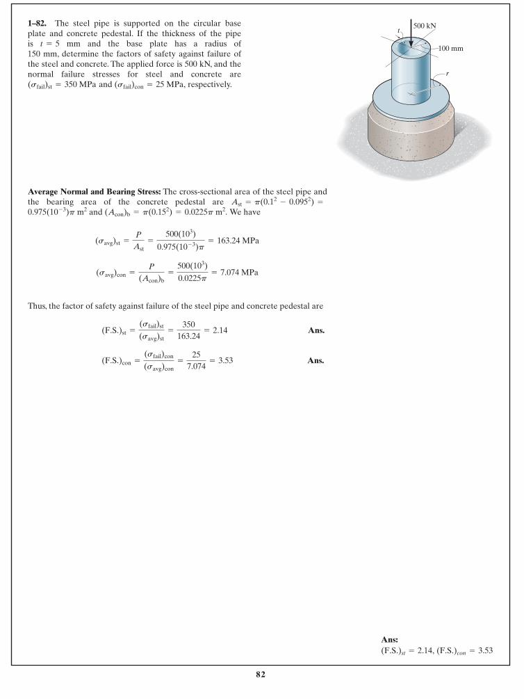
82
© 2014 Pearson Education, Inc., Upper Saddle River, NJ. All rights reserved. This material is protected under all copyright laws as they currentlyexist. No portion of this material may be reproduced, in any form or by any means, without permission in writing from the publisher.
1–82. The steel pipe is supported on the circular baseplate and concrete pedestal. If the thickness of the pipe is mm and the base plate has a radius of 150 mm, determine the factors of safety against failure ofthe steel and concrete. The applied force is 500 kN, and thenormal failure stresses for steel and concrete are
and respectively.(sfail)con = 25 MPa,(sfail)st = 350 MPa
t = 5
Average Normal and Bearing Stress: The cross-sectional area of the steel pipe andthe bearing area of the concrete pedestal are
and We have
Thus, the factor of safety against failure of the steel pipe and concrete pedestal are
Ans.
Ans.(F.S.)con =
(sfail)con
(savg)con=
257.074
= 3.53
(F.S.)st =
(sfail)st
(savg)st=
350163.24
= 2.14
(savg)con =
P
(Acon)b=
500(103)
0.0225p= 7.074 MPa
(savg)st =
P
Ast=
500(103)
0.975(10- 3)p= 163.24 MPa
(Acon)b = p(0.152) = 0.0225p m2.0.975(10- 3)p m2Ast = p(0.12
- 0.0952) =
r
t
100 mm
500 kN
Ans:(F.S.)con = 3.53(F.S.)st = 2.14,
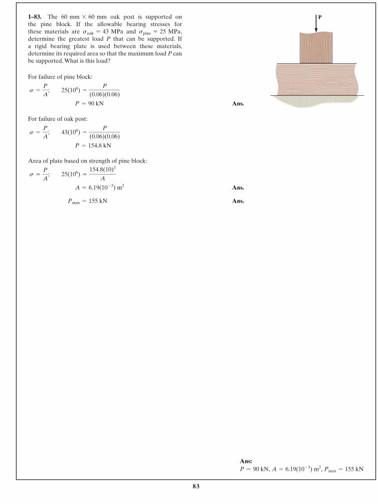
83
© 2014 Pearson Education, Inc., Upper Saddle River, NJ. All rights reserved. This material is protected under all copyright laws as they currentlyexist. No portion of this material may be reproduced, in any form or by any means, without permission in writing from the publisher.
For failure of pine block:
Ans.
For failure of oak post:
Area of plate based on strength of pine block:
Ans.
Ans. Pmax = 155 kN
A = 6.19(10- 3) m2
s =
P
A; 25(106) =
154.8(10)3
A
P = 154.8 kN
s =
P
A; 43(106) =
P
(0.06)(0.06)
P = 90 kN
s =
P
A; 25(106) =
P
(0.06)(0.06)
1–83. The oak post is supported onthe pine block. If the allowable bearing stresses forthese materials are and ,determine the greatest load P that can be supported. Ifa rigid bearing plate is used between these materials,determine its required area so that the maximum load P canbe supported. What is this load?
spine = 25 MPasoak = 43 MPa
60 mm * 60 mm P
Ans: Pmax = 155 kNA = 6.19(10- 3) m2,P = 90 kN,
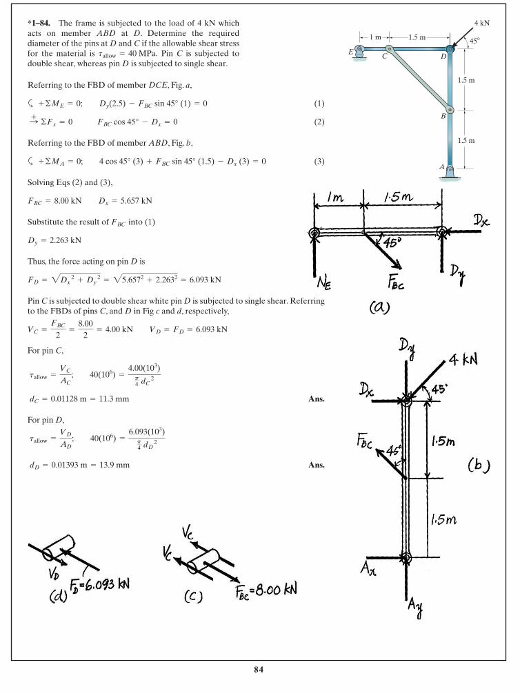
84
© 2014 Pearson Education, Inc., Upper Saddle River, NJ. All rights reserved. This material is protected under all copyright laws as they currentlyexist. No portion of this material may be reproduced, in any form or by any means, without permission in writing from the publisher.
*1–84. The frame is subjected to the load of 4 kN whichacts on member ABD at D. Determine the requireddiameter of the pins at D and C if the allowable shear stressfor the material is Pin C is subjected todouble shear, whereas pin D is subjected to single shear.
tallow = 40 MPa.
B
1.5 m
4 kN
45� 1.5 m1 m
1.5 m
DCE
A
Referring to the FBD of member DCE, Fig. a,
a (1)
(2)
Referring to the FBD of member ABD, Fig. b,
a (3)
Solving Eqs (2) and (3),
Substitute the result of into (1)
Thus, the force acting on pin D is
Pin C is subjected to double shear white pin D is subjected to single shear. Referringto the FBDs of pins C, and D in Fig c and d, respectively,
For pin C,
Ans.
For pin D,
Ans. dD = 0.01393 m = 13.9 mm
tallow =
VD
AD; 40(106) =
6.093(103)p4 dD
2
dC = 0.01128 m = 11.3 mm
tallow =
VC
AC; 40(106) =
4.00(103)p4 dC
2
VC =
FBC
2=
8.002
= 4.00 kN VD = FD = 6.093 kN
FD = 2Dx 2
+ Dy 2
= 25.6572+ 2.2632
= 6.093 kN
Dy = 2.263 kN
FBC
FBC = 8.00 kN Dx = 5.657 kN
+ ©MA = 0; 4 cos 45° (3) + FBC sin 45° (1.5) - Dx (3) = 0
:+ ©Fx = 0 FBC cos 45° - Dx = 0
+ ©ME = 0; Dy(2.5) - FBC sin 45° (1) = 0
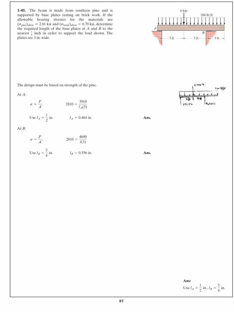
85
© 2014 Pearson Education, Inc., Upper Saddle River, NJ. All rights reserved. This material is protected under all copyright laws as they currentlyexist. No portion of this material may be reproduced, in any form or by any means, without permission in writing from the publisher.
1–85. The beam is made from southern pine and issupported by base plates resting on brick work. If theallowable bearing stresses for the materials are
and determinethe required length of the base plates at A and B to thenearest inch in order to support the load shown. The plates are 3 in. wide.
14
(sbrick)allow = 6.70 ksi,(spine)allow = 2.81 ksi
The design must be based on strength of the pine.
At A:
Use Ans.
At B:
Use Ans.lB = 0.556 in.lB =
34
in.
2810 =
4690l(3)
s =
P
A;
lA = 0.464 in.lA =
12
in.
2810 =
3910lA(3)
s =
P
A;
6 kip200 lb/ft
5 ft 3 ft5 ft
BA
Ans:
Use lB =
34
in.lA =
12
in.,
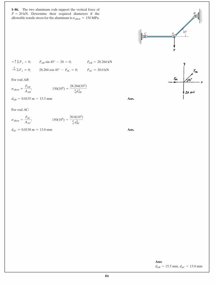
86
© 2014 Pearson Education, Inc., Upper Saddle River, NJ. All rights reserved. This material is protected under all copyright laws as they currentlyexist. No portion of this material may be reproduced, in any form or by any means, without permission in writing from the publisher.
1–86. The two aluminum rods support the vertical force ofDetermine their required diameters if the
allowable tensile stress for the aluminum is sallow = 150 MPa.P = 20 kN.
For rod AB:
Ans.
For rod AC:
Ans.dAC = 0.0130 m = 13.0 mm
150(106) =
20.0(103)p4 dAC 2sallow =
FAC
AAC;
dAB = 0.0155 m = 15.5 mm
150(106) =
28.284(103)p4dAB 2sallow =
FAB
AAB;
FAC = 20.0 kN28.284 cos 45° - FAC = 0; :+ ©Fx = 0;
FAB = 28.284 kNFAB sin 45° - 20 = 0; + c ©Fy = 0;
P
B
AC 45�
Ans:dAC = 13.0 mmdAB = 15.5 mm,
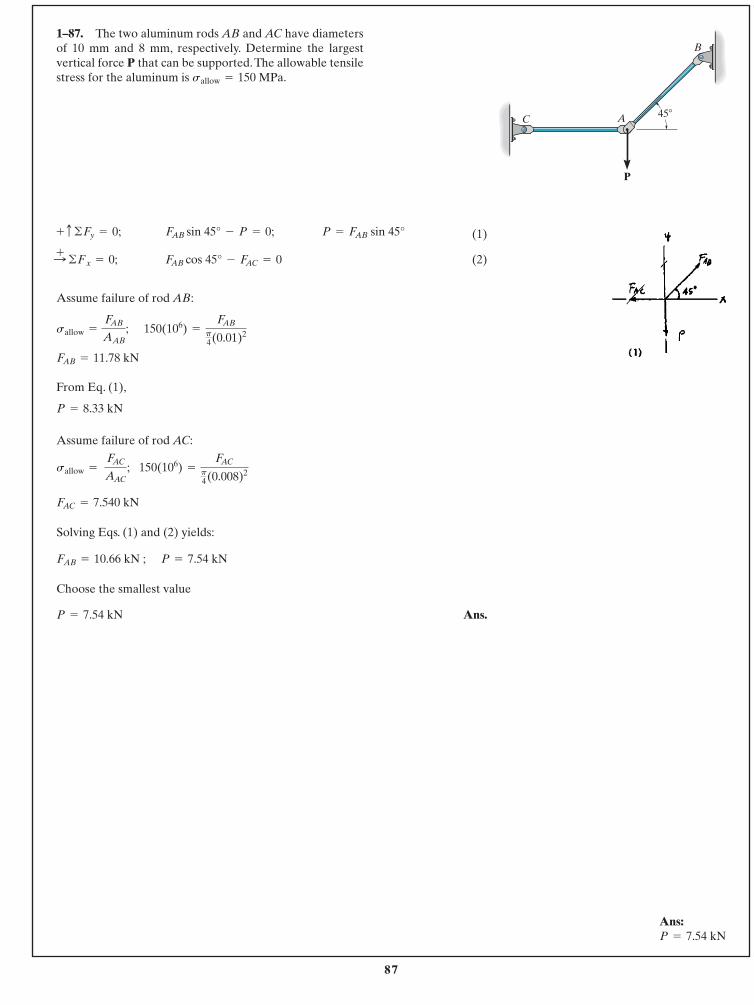
87
© 2014 Pearson Education, Inc., Upper Saddle River, NJ. All rights reserved. This material is protected under all copyright laws as they currentlyexist. No portion of this material may be reproduced, in any form or by any means, without permission in writing from the publisher.
(1)
(2)
Assume failure of rod AB:
From Eq. (1),
Assume failure of rod AC:
Solving Eqs. (1) and (2) yields:
Choose the smallest value
Ans.P = 7.54 kN
P = 7.54 kNFAB = 10.66 kN ;
FAC = 7.540 kN
150(106) =
FACp4(0.008)2sallow =
FAC
AAC;
P = 8.33 kN
FAB = 11.78 kN
150(106) =
FABp4(0.01)2sallow =
FAB
AAB;
FAB cos 45° - FAC = 0 :+ ©Fx = 0;
P = FAB sin 45°FAB sin 45° - P = 0; + c ©Fy = 0;
1–87. The two aluminum rods AB and AC have diametersof 10 mm and 8 mm, respectively. Determine the largestvertical force P that can be supported.The allowable tensilestress for the aluminum is sallow = 150 MPa.
P
B
AC 45�
Ans:P = 7.54 kN
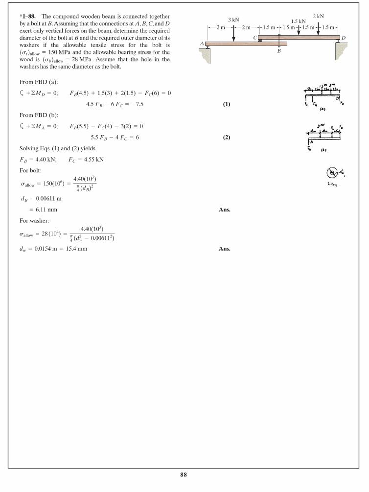
88
© 2014 Pearson Education, Inc., Upper Saddle River, NJ. All rights reserved. This material is protected under all copyright laws as they currentlyexist. No portion of this material may be reproduced, in any form or by any means, without permission in writing from the publisher.
From FBD (a):
a
(1)
From FBD (b):
a
(2)
Solving Eqs. (1) and (2) yields
For bolt:
Ans.
For washer:
Ans.dw = 0.0154 m = 15.4 mm
sallow = 28 (104) =
4.40(103)p4 (d2
w - 0.006112)
= 6.11 mm
dB = 0.00611 m
sallow = 150(106) =
4.40(103)p4 (dB)2
FB = 4.40 kN; FC = 4.55 kN
5.5 FB - 4 FC = 6
+ ©MA = 0; FB(5.5) - FC(4) - 3(2) = 0
4.5 FB - 6 FC = -7.5
+ ©MD = 0; FB(4.5) + 1.5(3) + 2(1.5) - FC(6) = 0
*1–88. The compound wooden beam is connected togetherby a bolt at B.Assuming that the connections at A, B, C, and Dexert only vertical forces on the beam, determine the requireddiameter of the bolt at B and the required outer diameter of itswashers if the allowable tensile stress for the bolt is
and the allowable bearing stress for thewood is Assume that the hole in thewashers has the same diameter as the bolt.
1sb2allow = 28 MPa.1st2allow = 150 MPa
1.5 m1.5 m1.5 m1.5 m2 m2 m
B
C DA
3 kN 1.5 kN2 kN
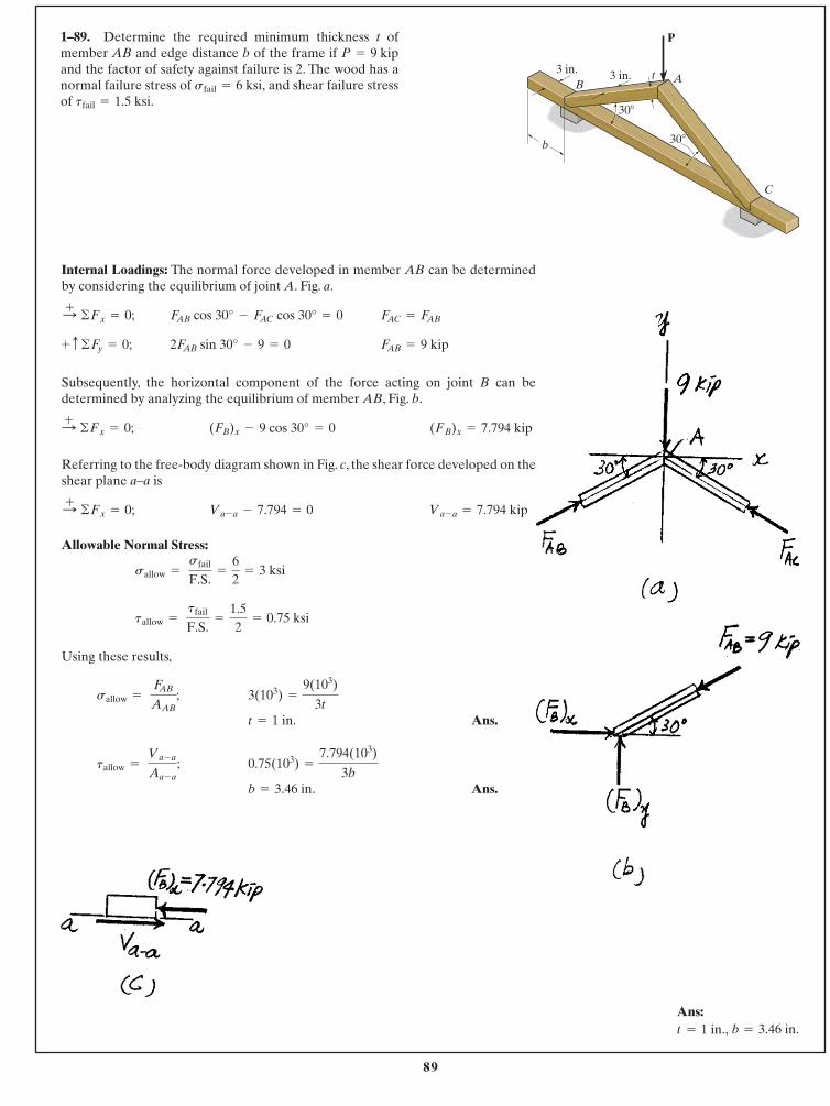
89
© 2014 Pearson Education, Inc., Upper Saddle River, NJ. All rights reserved. This material is protected under all copyright laws as they currentlyexist. No portion of this material may be reproduced, in any form or by any means, without permission in writing from the publisher.
Internal Loadings: The normal force developed in member AB can be determinedby considering the equilibrium of joint A. Fig. a.
Subsequently, the horizontal component of the force acting on joint B can bedetermined by analyzing the equilibrium of member AB, Fig. b.
Referring to the free-body diagram shown in Fig. c, the shear force developed on theshear plane a–a is
Allowable Normal Stress:
Using these results,
Ans.
Ans.b = 3.46 in.
0.75(103) =
7.794(103)
3btallow =
Va - a
Aa - a;
t = 1 in.
3(103) =
9(103)
3tsallow =
FAB
AAB;
tallow = tfail
F.S.=
1.52
= 0.75 ksi
sallow = sfail
F.S.=
62
= 3 ksi
Va - a = 7.794 kip Va - a - 7.794 = 0 :+ ©Fx = 0;
(FB)x = 7.794 kip (FB)x - 9 cos 30° = 0 :+ ©Fx = 0;
FAB = 9 kip 2FAB sin 30° - 9 = 0 + c ©Fy = 0;
FAC = FABFAB cos 30° - FAC cos 30° = 0 :+ ©Fx = 0;
1–89. Determine the required minimum thickness t ofmember AB and edge distance b of the frame if and the factor of safety against failure is 2. The wood has anormal failure stress of and shear failure stressof tfail = 1.5 ksi.
sfail = 6 ksi,
P = 9 kipP
b
B
C
At3 in. 3 in.
30�
30�
Ans:b = 3.46 in.t = 1 in.,
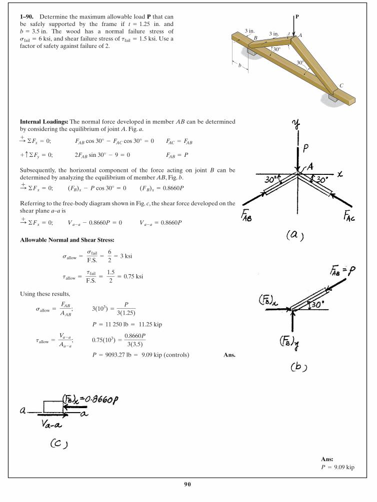
90
© 2014 Pearson Education, Inc., Upper Saddle River, NJ. All rights reserved. This material is protected under all copyright laws as they currentlyexist. No portion of this material may be reproduced, in any form or by any means, without permission in writing from the publisher.
1–90. Determine the maximum allowable load P that canbe safely supported by the frame if in. and
The wood has a normal failure stress ofand shear failure stress of Use a
factor of safety against failure of 2.tfail = 1.5 ksi.sfail = 6 ksi,
b = 3.5 in.t = 1.25
Internal Loadings: The normal force developed in member AB can be determinedby considering the equilibrium of joint A. Fig. a.
Subsequently, the horizontal component of the force acting on joint B can bedetermined by analyzing the equilibrium of member AB, Fig. b.
Referring to the free-body diagram shown in Fig. c, the shear force developed on theshear plane a–a is
Allowable Normal and Shear Stress:
Using these results,
Ans.P = 9093.27 lb = 9.09 kip ( controls)
0.75( 103) =
0.8660P
3( 3.5)tallow =
Va - a
Aa - a;
P = 11 250 lb = 11.25 kip
3(103) =
P
3( 1.25)sallow =
FAB
AAB;
tallow = tfail
F.S.=
1.52
= 0.75 ksi
sallow = sfail
F.S.=
62
= 3 ksi
Va - a = 0.8660PVa - a - 0.8660P = 0 :+ ©Fx = 0;
(FB)x = 0.8660P(FB)x - P cos 30° = 0 :+ ©Fx = 0;
FAB = P2FAB sin 30° - 9 = 0 + c ©Fy = 0;
FAC = FABFAB cos 30° - FAC cos 30° = 0 :+ ©Fx = 0;
P
b
B
C
At3 in. 3 in.
30�
30�
Ans:P = 9.09 kip
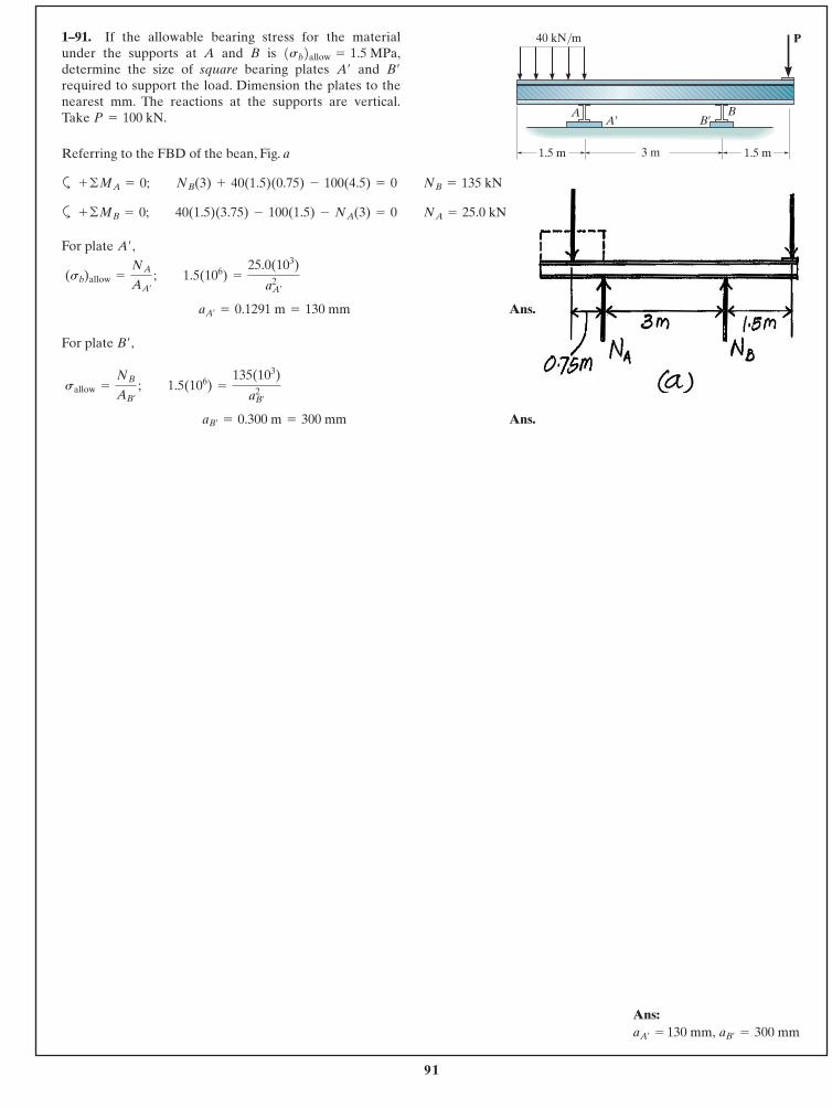
91
© 2014 Pearson Education, Inc., Upper Saddle River, NJ. All rights reserved. This material is protected under all copyright laws as they currentlyexist. No portion of this material may be reproduced, in any form or by any means, without permission in writing from the publisher.
Referring to the FBD of the bean, Fig. a
a
a
For plate ,
Ans.
For plate ,
Ans. aB¿= 0.300 m = 300 mm
sallow =
NB
AB¿
; 1.5(106) =
135(103)
a2B¿
B¿
aA¿= 0.1291 m = 130 mm
(sb)allow =
NA
AA¿
; 1.5(106) =
25.0(103)
a2A¿
A¿
+ ©MB = 0; 40(1.5)(3.75) - 100(1.5) - NA(3) = 0 NA = 25.0 kN
+ ©MA = 0; NB(3) + 40(1.5)(0.75) - 100(4.5) = 0 NB = 135 kN
1–91. If the allowable bearing stress for the materialunder the supports at A and B is determine the size of square bearing plates and required to support the load. Dimension the plates to thenearest mm. The reactions at the supports are vertical.Take P = 100 kN.
B¿A¿
1sb2allow = 1.5 MPa,
3 m
P
A¿ B¿A B
40 kN/m
1.5 m 1.5 m
Ans: aB¿
= 300 mmaA¿= 130 mm,
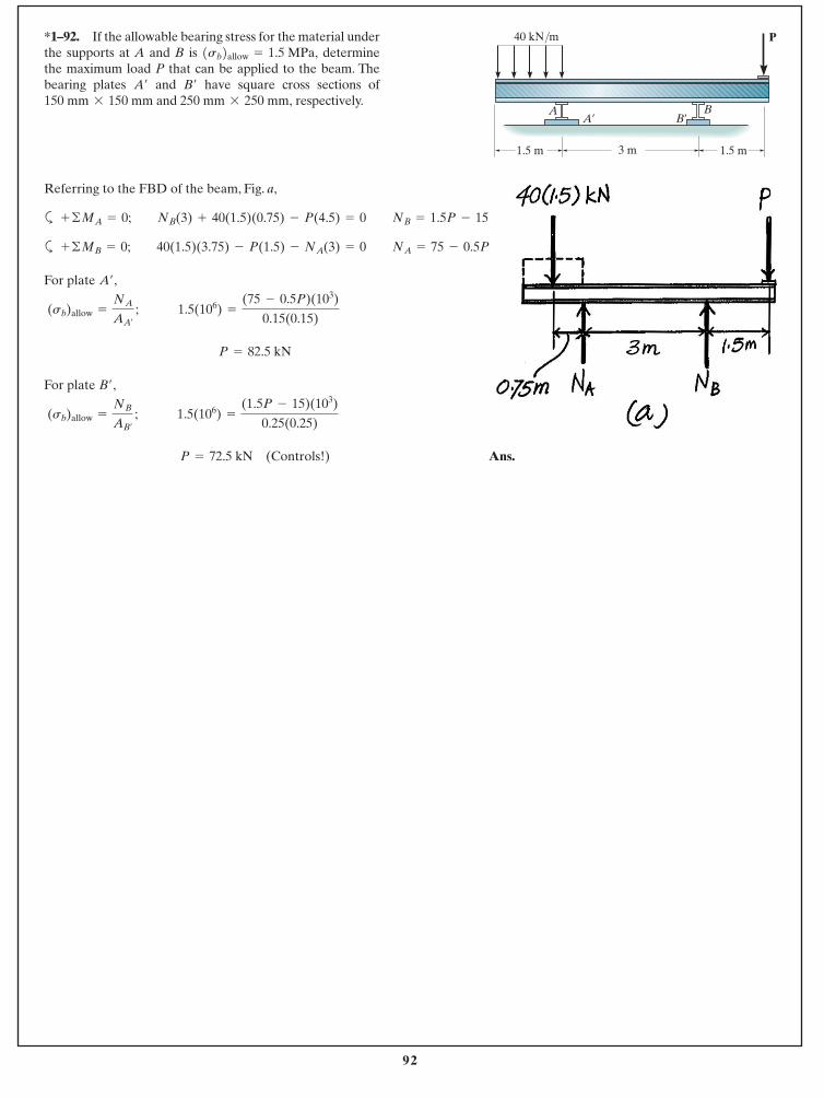
92
© 2014 Pearson Education, Inc., Upper Saddle River, NJ. All rights reserved. This material is protected under all copyright laws as they currentlyexist. No portion of this material may be reproduced, in any form or by any means, without permission in writing from the publisher.
*1–92. If the allowable bearing stress for the material underthe supports at A and B is determinethe maximum load P that can be applied to the beam. Thebearing plates and have square cross sections of
and respectively.250 mm * 250 mm,150 mm * 150 mmB¿A¿
1sb2allow = 1.5 MPa,
3 m
P
A¿ B¿A B
40 kN/m
1.5 m 1.5 m
Referring to the FBD of the beam, Fig. a,
a
a
For plate ,
For plate ,
Ans. P = 72.5 kN (Controls!)
(sb)allow =
NB
AB¿
; 1.5(106) =
(1.5P - 15)(103)
0.25(0.25)
B¿
P = 82.5 kN
(sb)allow =
NA
AA¿
; 1.5(106) =
(75 - 0.5P)(103)
0.15(0.15)
A¿
+ ©MB = 0; 40(1.5)(3.75) - P(1.5) - NA(3) = 0 NA = 75 - 0.5P
+ ©MA = 0; NB(3) + 40(1.5)(0.75) - P(4.5) = 0 NB = 1.5P - 15
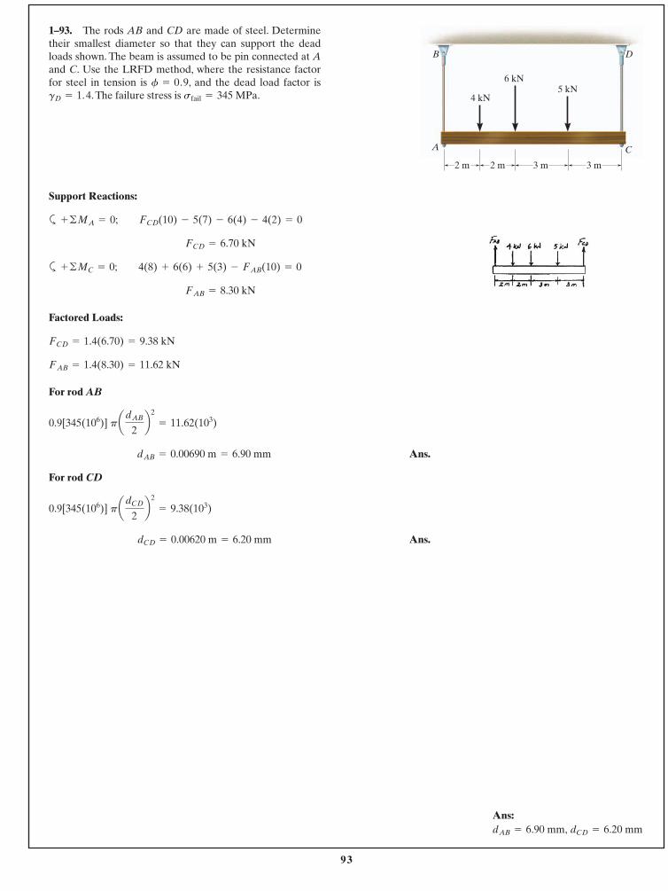
93
© 2014 Pearson Education, Inc., Upper Saddle River, NJ. All rights reserved. This material is protected under all copyright laws as they currentlyexist. No portion of this material may be reproduced, in any form or by any means, without permission in writing from the publisher.
1–93. The rods AB and CD are made of steel. Determinetheir smallest diameter so that they can support the deadloads shown. The beam is assumed to be pin connected at Aand C. Use the LRFD method, where the resistance factorfor steel in tension is , and the dead load factor is
.The failure stress is sfail = 345 MPa.gD = 1.4f = 0.9
B
A
D
C
4 kN
6 kN5 kN
3 m2 m2 m 3 m
Support Reactions:
a
a
Factored Loads:
For rod AB
Ans.
For rod CD
Ans. dCD = 0.00620 m = 6.20 mm
0.9[345(106)] padCD
2b2
= 9.38(103)
dAB = 0.00690 m = 6.90 mm
0.9[345(106)] padAB
2b2
= 11.62(103)
FAB = 1.4(8.30) = 11.62 kN
FCD = 1.4(6.70) = 9.38 kN
FAB = 8.30 kN
+ ©MC = 0; 4(8) + 6(6) + 5(3) - FAB(10) = 0
FCD = 6.70 kN
+ ©MA = 0; FCD(10) - 5(7) - 6(4) - 4(2) = 0
Ans:dCD = 6.20 mmdAB = 6.90 mm,
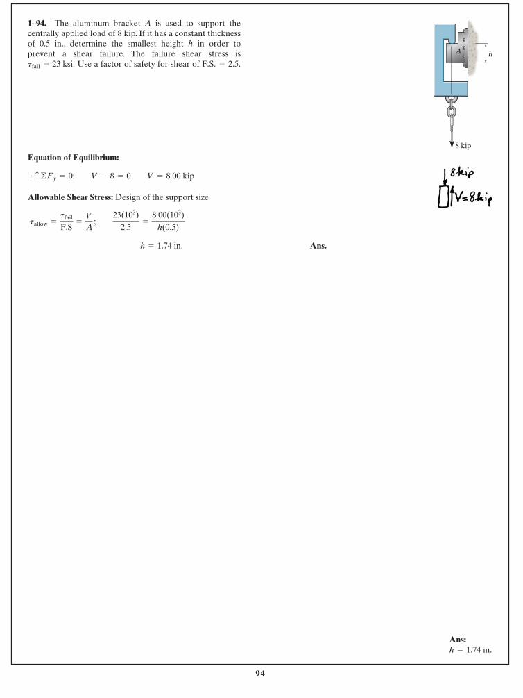
94
© 2014 Pearson Education, Inc., Upper Saddle River, NJ. All rights reserved. This material is protected under all copyright laws as they currentlyexist. No portion of this material may be reproduced, in any form or by any means, without permission in writing from the publisher.
Equation of Equilibrium:
Allowable Shear Stress: Design of the support size
Ans. h = 1.74 in.
tallow =
tfail
F.S=
V
A ; 23(103)
2.5=
8.00(103)
h(0.5)
+ c ©Fy = 0; V - 8 = 0 V = 8.00 kip
1–94. The aluminum bracket A is used to support thecentrally applied load of 8 kip. If it has a constant thicknessof 0.5 in., determine the smallest height h in order toprevent a shear failure. The failure shear stress is
Use a factor of safety for shear of F.S. = 2.5.tfail = 23 ksi.
8 kip
hA
Ans:h = 1.74 in.
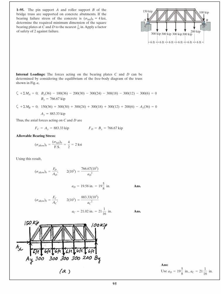
95
© 2014 Pearson Education, Inc., Upper Saddle River, NJ. All rights reserved. This material is protected under all copyright laws as they currentlyexist. No portion of this material may be reproduced, in any form or by any means, without permission in writing from the publisher.
1–95. The pin support A and roller support B of thebridge truss are supported on concrete abutments. If thebearing failure stress of the concrete is determine the required minimum dimension of the squarebearing plates at C and D to the nearest in.Apply a factorof safety of 2 against failure.
116
(sfail)b = 4 ksi,
Internal Loadings: The forces acting on the bearing plates C and D can bedetermined by considering the equilibrium of the free-body diagram of the trussshown in Fig. a,
a
a
Ay = 883.33 kip
150(36) + 300(30) + 300(24) + 300(18) + 300(12) + 200(6) - Ay(36) = 0+ ©MB = 0;
By = 766.67 kip
By(36) - 100(36) - 200(30) - 300(24) - 300(18) - 300(12) - 300(6) = 0+ ©MA = 0;
Thus, the axial forces acting on C and D are
Allowable Bearing Stress:
Using this result,
Ans.
Ans.aC = 21.02 in. = 21 116
in.
2(103) =
883.33(103)
aC2(sallow)b =
FC
AC;
aD = 19.58 in. = 19 58
in.
2(103) =
766.67(103)
aD2(sallow)b =
FD
AD;
(sallow)b =
(sfail)b
F.S.=
42
= 2 ksi
FD = By = 766.67 kip FC = Ay = 883.33 kip
A
C D
B
6 ft
150 kip 100 kip
200 kip300 kip300 kip300 kip 300 kip
6 ft 6 ft 6 ft 6 ft 6 ft
Ans:
Use aC = 21 116
in.aD = 19 58
in.,
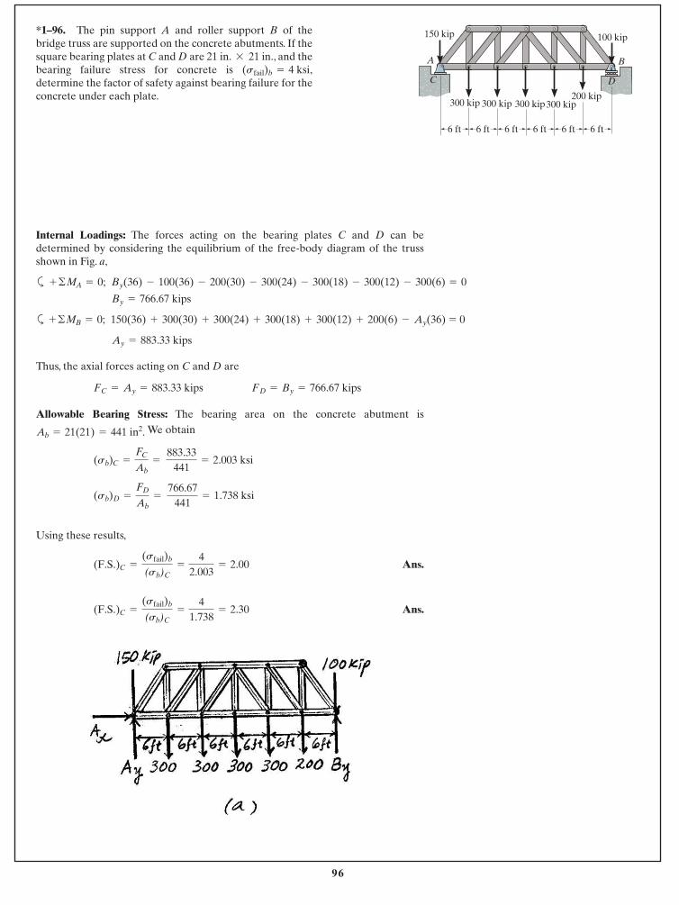
96
© 2014 Pearson Education, Inc., Upper Saddle River, NJ. All rights reserved. This material is protected under all copyright laws as they currentlyexist. No portion of this material may be reproduced, in any form or by any means, without permission in writing from the publisher.
*1–96. The pin support A and roller support B of thebridge truss are supported on the concrete abutments. If thesquare bearing plates at C and D are 21 in. 21 in., and thebearing failure stress for concrete is determine the factor of safety against bearing failure for theconcrete under each plate.
(sfail)b = 4 ksi,*
Internal Loadings: The forces acting on the bearing plates C and D can bedetermined by considering the equilibrium of the free-body diagram of the trussshown in Fig. a,
a
a
Ay = 883.33 kips
150(36) + 300(30) + 300(24) + 300(18) + 300(12) + 200(6) - Ay(36) = 0+ ©MB = 0;
By = 766.67 kips
By(36) - 100(36) - 200(30) - 300(24) - 300(18) - 300(12) - 300(6) = 0+ ©MA = 0;
Thus, the axial forces acting on C and D are
Allowable Bearing Stress: The bearing area on the concrete abutment isWe obtain
Using these results,
Ans.
Ans.(F.S.) C =
(sfail)b
(s b)C=
41.738
= 2.30
(F.S.) C =
(sfail)b
(s b)C=
42.003
= 2.00
(sb)D =
FD
Ab=
766.67441
= 1.738 ksi
(sb)C =
FC
Ab=
883.33441
= 2.003 ksi
Ab = 21(21) = 441 in2.
FD = By = 766.67 kips FC = Ay = 883.33 kips
A
C D
B
6 ft
150 kip 100 kip
200 kip300 kip300 kip300 kip 300 kip
6 ft 6 ft 6 ft 6 ft 6 ft
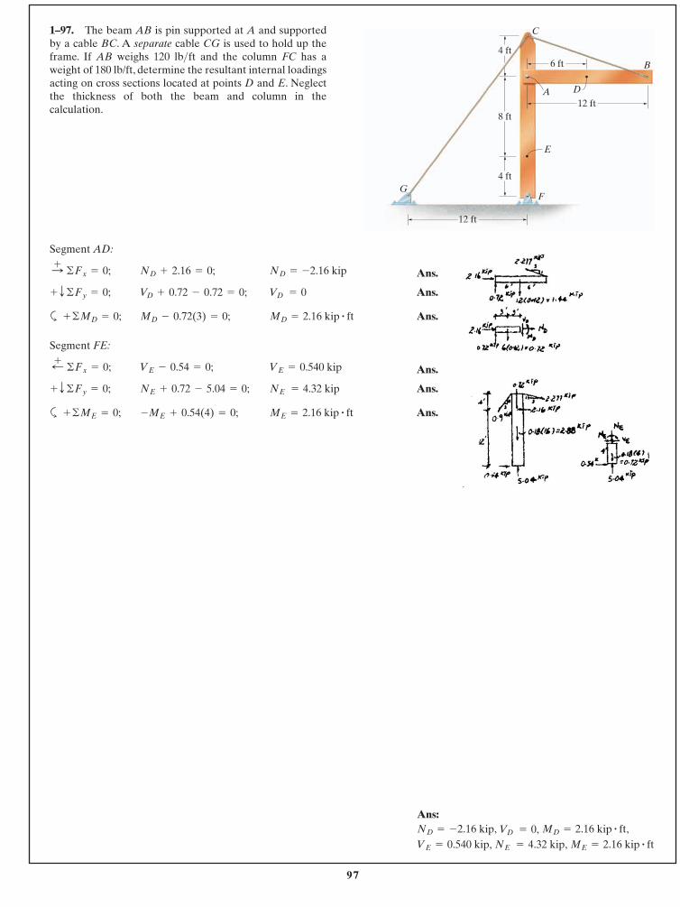
97
© 2014 Pearson Education, Inc., Upper Saddle River, NJ. All rights reserved. This material is protected under all copyright laws as they currentlyexist. No portion of this material may be reproduced, in any form or by any means, without permission in writing from the publisher.
1–97. The beam AB is pin supported at A and supportedby a cable BC. A separate cable CG is used to hold up theframe. If AB weighs 120 lb ft and the column FC has aweight of 180 lb/ft, determine the resultant internal loadingsacting on cross sections located at points D and E. Neglectthe thickness of both the beam and column in thecalculation.
>
Segment AD:
Ans.
Ans.
a Ans.
Segment FE:
Ans.
Ans.
a Ans.ME = 2.16 kip # ft-ME + 0.54(4) = 0;+ ©ME = 0;
NE = 4.32 kipNE + 0.72 - 5.04 = 0;+ T ©Fy = 0;
VE = 0.540 kipVE - 0.54 = 0;;+ ©Fx = 0;
MD = 2.16 kip # ftMD - 0.72(3) = 0;+ ©MD = 0;
VD = 0VD + 0.72 - 0.72 = 0;+ T ©Fy = 0;
ND = -2.16 kipND + 2.16 = 0; :+ ©Fx = 0;
4 ft
12 ft
4 ft
8 ft12 ft
6 ft
A
E
G
B
F
D
C
Ans:
ME = 2.16 kip # ftNE = 4.32 kip,VE = 0.540 kip,MD = 2.16 kip # ft,VD = 0,ND = -2.16 kip,
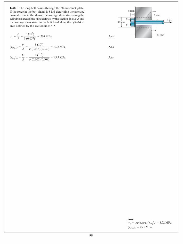
98
© 2014 Pearson Education, Inc., Upper Saddle River, NJ. All rights reserved. This material is protected under all copyright laws as they currentlyexist. No portion of this material may be reproduced, in any form or by any means, without permission in writing from the publisher.
Ans.
Ans.
Ans.(tavg)b =
V
A=
8 (103)
p (0.007)(0.008)= 45.5 MPa
(tavg)a =
V
A=
8 (103)
p (0.018)(0.030)= 4.72 MPa
ss =
P
A=
8 (103)p4 (0.007)2 = 208 MPa
1–98. The long bolt passes through the 30-mm-thick plate.If the force in the bolt shank is 8 kN, determine the averagenormal stress in the shank, the average shear stress along thecylindrical area of the plate defined by the section lines a–a, andthe average shear stress in the bolt head along the cylindricalarea defined by the section lines b–b.
8 kN18 mm
7 mm
30 mm
8 mm a
a
b
b
Ans:
(tavg)b = 45.5 MPa
(tavg)a = 4.72 MPa,ss = 208 MPa,
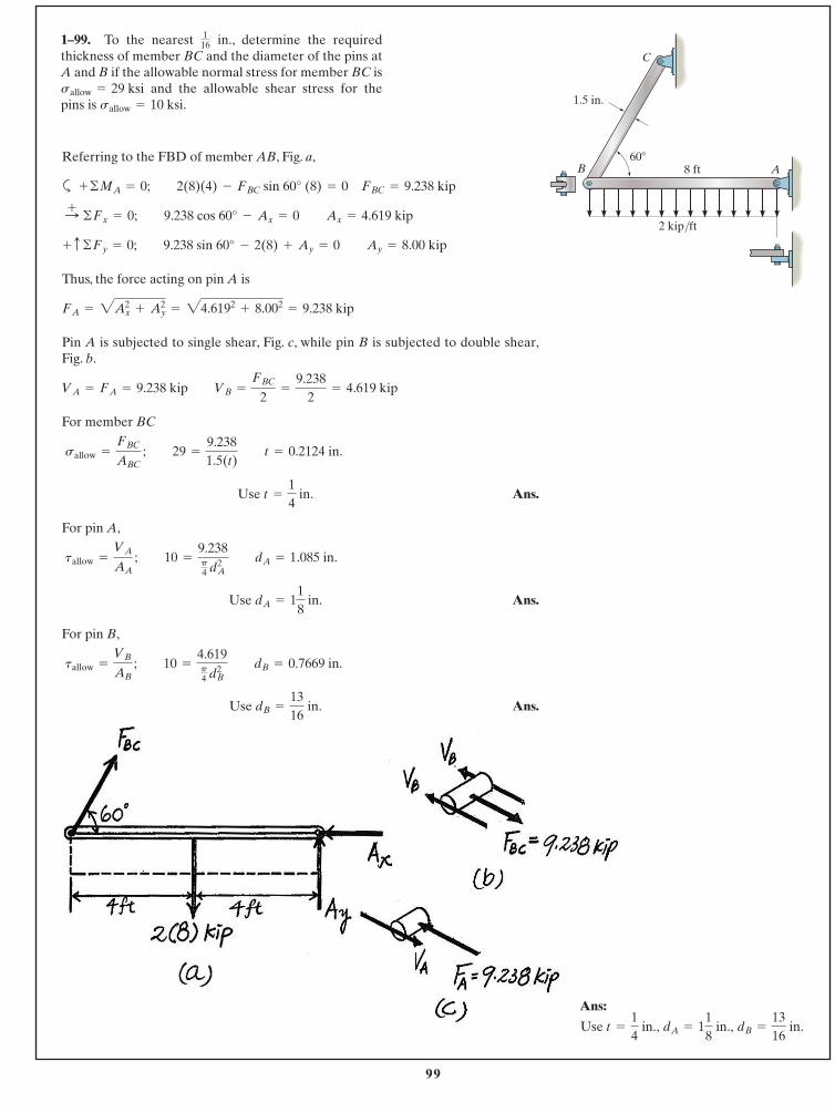
99
© 2014 Pearson Education, Inc., Upper Saddle River, NJ. All rights reserved. This material is protected under all copyright laws as they currentlyexist. No portion of this material may be reproduced, in any form or by any means, without permission in writing from the publisher.
Referring to the FBD of member AB, Fig. a,
a
Thus, the force acting on pin A is
Pin A is subjected to single shear, Fig. c, while pin B is subjected to double shear,Fig. b.
For member BC
Ans.
For pin A,
Ans.
For pin B,
Ans. Use dB =
1316
in.
tallow =
VB
AB ; 10 =
4.619p4 dB
2 dB = 0.7669 in.
Use dA = 118
in.
tallow =
VA
AA ; 10 =
9.238p4 d2
A dA = 1.085 in.
Use t =
14
in.
sallow =
FBC
ABC ; 29 =
9.2381.5(t) t = 0.2124 in.
VA = FA = 9.238 kip VB =
FBC
2=
9.2382
= 4.619 kip
FA = 2Ax2
+ Ay2
= 24.6192+ 8.002
= 9.238 kip
+ c ©Fy = 0; 9.238 sin 60° - 2(8) + Ay = 0 Ay = 8.00 kip
:+ ©Fx = 0; 9.238 cos 60° - Ax = 0 Ax = 4.619 kip
+ ©MA = 0; 2(8)(4) - FBC sin 60° (8) = 0 FBC = 9.238 kip
1–99. To the nearest in., determine the requiredthickness of member BC and the diameter of the pins atA and B if the allowable normal stress for member BC is
and the allowable shear stress for thepins is sallow = 10 ksi.sallow = 29 ksi
116
C
60�8 ftB A
2 kip/ft
1.5 in.
Ans:
dB =
1316
in.dA = 118
in., Use t =
14
in.,
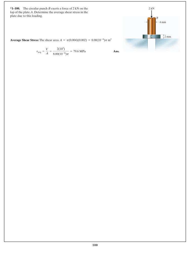
100
© 2014 Pearson Education, Inc., Upper Saddle River, NJ. All rights reserved. This material is protected under all copyright laws as they currentlyexist. No portion of this material may be reproduced, in any form or by any means, without permission in writing from the publisher.
Average Shear Stress: The shear area
Ans.tavg =
V
A=
2(103)
8.00(10- 6)p= 79.6 MPa
A = p(0.004)(0.002) = 8.00(10- 6)p m2
*1–100. The circular punch B exerts a force of 2 kN on thelop of the plate A. Determine the average shear stress in theplate due to this loading.
2 kN
2 mm
B
A
4 mm
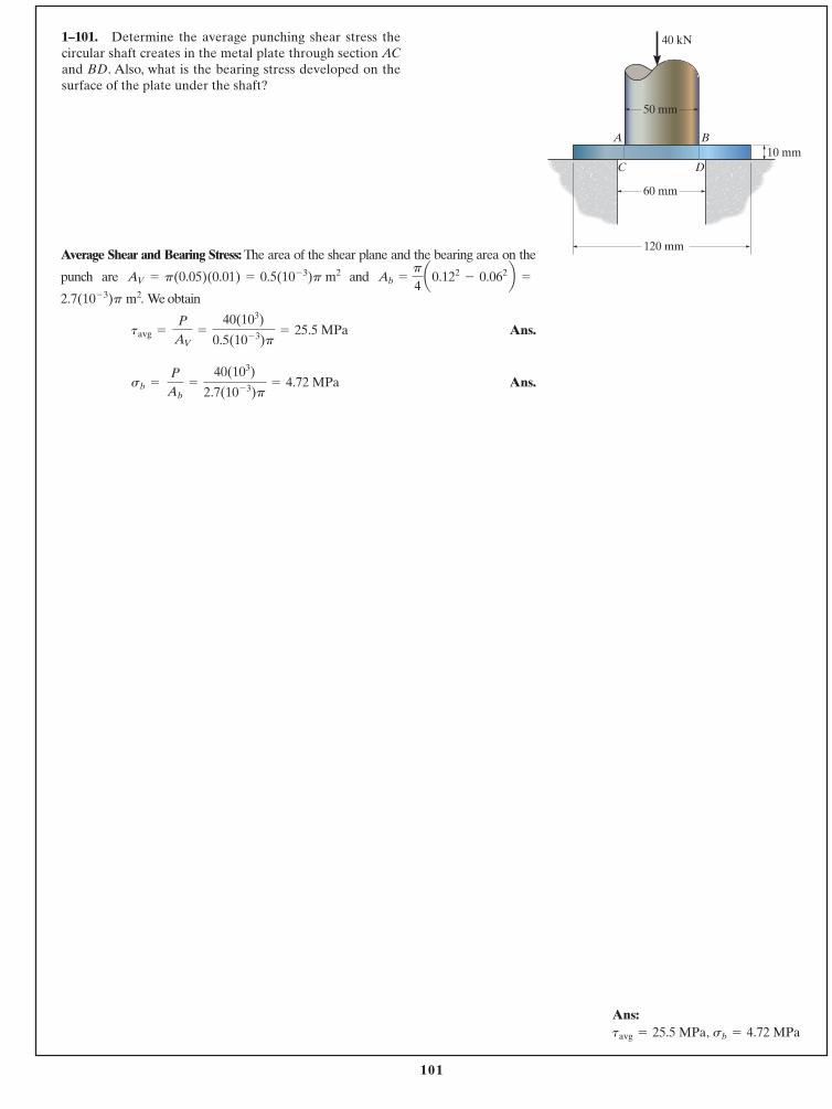
101
© 2014 Pearson Education, Inc., Upper Saddle River, NJ. All rights reserved. This material is protected under all copyright laws as they currentlyexist. No portion of this material may be reproduced, in any form or by any means, without permission in writing from the publisher.
1–101. Determine the average punching shear stress thecircular shaft creates in the metal plate through section ACand BD. Also, what is the bearing stress developed on thesurface of the plate under the shaft?
Average Shear and Bearing Stress: The area of the shear plane and the bearing area on the
punch are and
. We obtain
Ans.
Ans.sb = P
Ab=
40(103)
2.7(10- 3)p= 4.72 MPa
tavg = P
AV=
40(103)
0.5(10- 3)p= 25.5 MPa
2.7(10- 3)p m2
p
4a0.122
- 0.062b =Ab =AV = p(0.05)(0.01) = 0.5(10- 3)p m2
50 mm
10 mm
40 kN
60 mm
120 mm
A
C D
B
Ans:sb = 4.72 MPa tavg = 25.5 MPa,
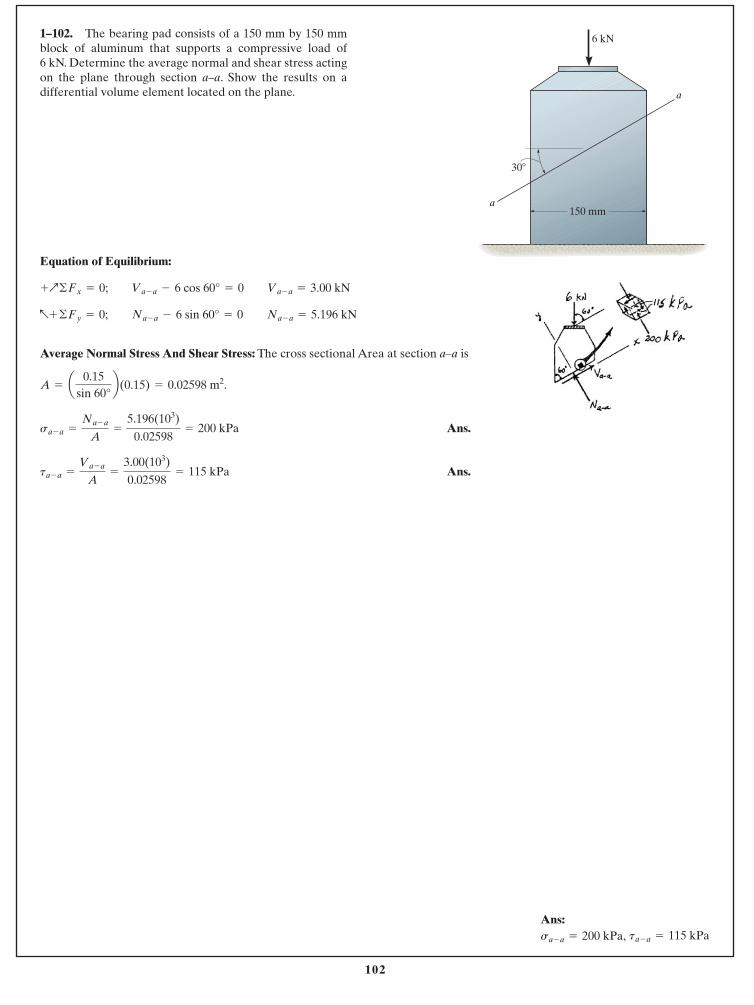
102
© 2014 Pearson Education, Inc., Upper Saddle River, NJ. All rights reserved. This material is protected under all copyright laws as they currentlyexist. No portion of this material may be reproduced, in any form or by any means, without permission in writing from the publisher.
Equation of Equilibrium:
Average Normal Stress And Shear Stress: The cross sectional Area at section a–a is
.
Ans.
Ans.ta - a =
Va - a
A=
3.00(103)
0.02598= 115 kPa
sa - a =
Na - a
A=
5.196(103)
0.02598= 200 kPa
A = a 0.15sin 60°
b(0.15) = 0.02598 m2
a+ ©Fy = 0; Na - a - 6 sin 60° = 0 Na - a = 5.196 kN
+Q©Fx = 0; Va - a - 6 cos 60° = 0 Va - a = 3.00 kN
1–102. The bearing pad consists of a 150 mm by 150 mmblock of aluminum that supports a compressive load of6 kN. Determine the average normal and shear stress actingon the plane through section a–a. Show the results on adifferential volume element located on the plane.
30�
150 mm
6 kN
a
a
Ans:ta - a = 115 kPasa - a = 200 kPa,
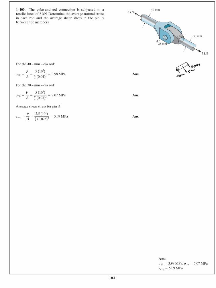
103
© 2014 Pearson Education, Inc., Upper Saddle River, NJ. All rights reserved. This material is protected under all copyright laws as they currentlyexist. No portion of this material may be reproduced, in any form or by any means, without permission in writing from the publisher.
1–103. The yoke-and-rod connection is subjected to atensile force of 5 kN. Determine the average normal stressin each rod and the average shear stress in the pin Abetween the members.
For the 40 – mm – dia rod:
Ans.
For the 30 – mm – dia rod:
Ans.
Average shear stress for pin A:
Ans.tavg =
P
A=
2.5 (103)p4 (0.025)2 = 5.09 MPa
s30 =
V
A=
5 (103)p4 (0.03)2 = 7.07 MPa
s40 =
P
A=
5 (103)p4 (0.04)2 = 3.98 MPa
25 mm
40 mm
30 mm
A
5 kN
5 kN
Ans:
tavg = 5.09 MPas30 = 7.07 MPas40 = 3.98 MPa,
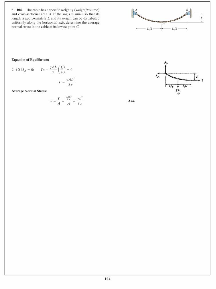
104
© 2014 Pearson Education, Inc., Upper Saddle River, NJ. All rights reserved. This material is protected under all copyright laws as they currentlyexist. No portion of this material may be reproduced, in any form or by any means, without permission in writing from the publisher.
Equation of Equilibrium:
a
Average Normal Stress:
Ans.s =
T
A=
gAL2
8 s
A=
gL2
8 s
T =
gAL2
8 s
+ ©MA = 0; Ts -
gAL
2 aL
4b = 0
*1–104. The cable has a specific weight and cross-sectional area A. If the sag s is small, so that itslength is approximately L and its weight can be distributeduniformly along the horizontal axis, determine the averagenormal stress in the cable at its lowest point C.
(weight>volume)g
s
L/2 L/2
C
A B
105
© 2014 Pearson Education, Inc., Upper Saddle River, NJ. All rights reserved. This material is protected under all copyright laws as they currentlyexist. No portion of this material may be reproduced, in any form or by any means, without permission in writing from the publisher.
Ans. P =
pd - pd0
pd0=
7 - 66
= 0.167 in.>in.
d = 7 in.
d0 = 6 in.
2–1. An air-filled rubber ball has a diameter of 6 in. If the airpressure within it is increased until the ball’s diameterbecomes 7 in., determine the average normal strain in therubber.
Ans: P = 0.167 in.>in.
106
© 2014 Pearson Education, Inc., Upper Saddle River, NJ. All rights reserved. This material is protected under all copyright laws as they currentlyexist. No portion of this material may be reproduced, in any form or by any means, without permission in writing from the publisher.
Ans.P =
L - L0
L0=
5p - 1515
= 0.0472 in.>in.
L = p(5 in.)
L0 = 15 in.
2–2. A thin strip of rubber has an unstretched length of 15 in. If it is stretched around a pipe having an outerdiameter of 5 in., determine the average normal strain inthe strip.
Ans:P = 0.0472 in.>in.
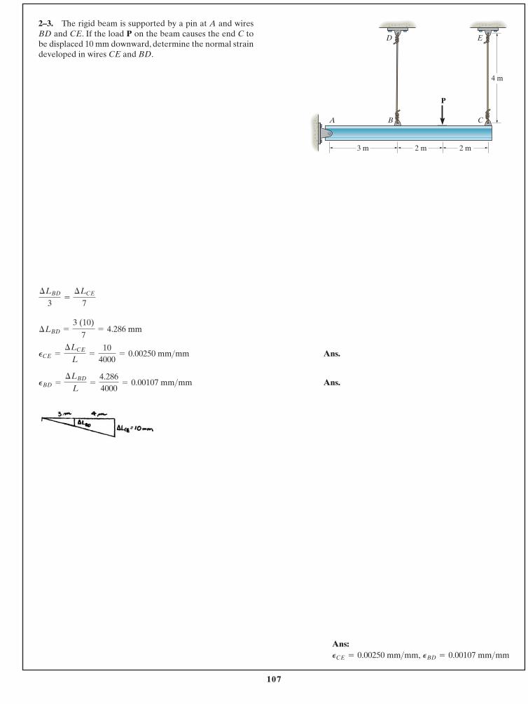
107
© 2014 Pearson Education, Inc., Upper Saddle River, NJ. All rights reserved. This material is protected under all copyright laws as they currentlyexist. No portion of this material may be reproduced, in any form or by any means, without permission in writing from the publisher.
2–3. The rigid beam is supported by a pin at A and wiresBD and CE. If the load P on the beam causes the end C tobe displaced 10 mm downward, determine the normal straindeveloped in wires CE and BD.
C
3 m
ED
2 m
4 m
P
BA
2 m
Ans.
Ans.PBD =
¢LBD
L=
4.2864000
= 0.00107 mm>mm
PCE =
¢LCE
L=
104000
= 0.00250 mm>mm
¢LBD =
3 (10)
7= 4.286 mm
¢LBD
3=
¢LCE
7
Ans:PBD = 0.00107 mm>mmPCE = 0.00250 mm>mm,
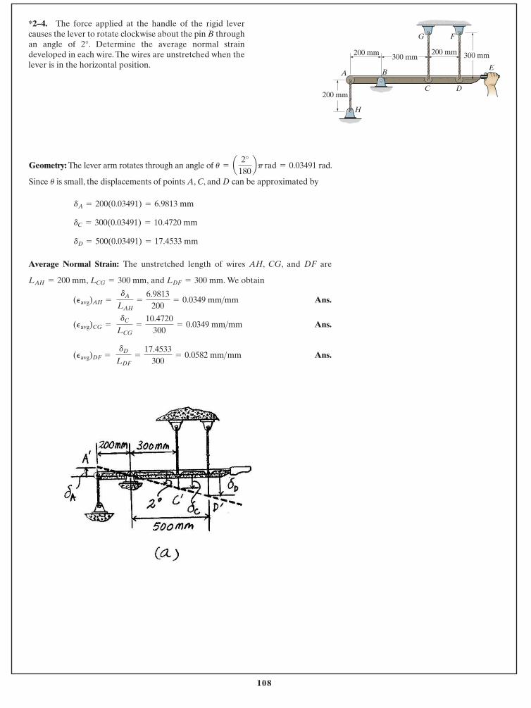
108
© 2014 Pearson Education, Inc., Upper Saddle River, NJ. All rights reserved. This material is protected under all copyright laws as they currentlyexist. No portion of this material may be reproduced, in any form or by any means, without permission in writing from the publisher.
dD = 500(0.03491) = 17.4533 mm
dC = 300(0.03491) = 10.4720 mm
dA = 200(0.03491) = 6.9813 mm
Geometry: The lever arm rotates through an angle of rad.
Since is small, the displacements of points A, C, and D can be approximated byu
u = a 2°180bp rad = 0.03491
Average Normal Strain: The unstretched length of wires AH, CG, and DF are
and We obtainLDF = 300 mm.LAH = 200 mm, LCG = 300 mm,
Ans.
Ans.
Ans.(Pavg)DF = dD
LDF=
17.4533300
= 0.0582 mm >mm
(Pavg)CG = dC
LCG=
10.4720300
= 0.0349 mm > mm
(Pavg)AH = dA
LAH=
6.9813200
= 0.0349 mm>mm
*2–4. The force applied at the handle of the rigid levercauses the lever to rotate clockwise about the pin B throughan angle of 2°. Determine the average normal straindeveloped in each wire. The wires are unstretched when thelever is in the horizontal position.
A B
C
H
D
G F
E
200 mm
200 mm 200 mm300 mm 300 mm
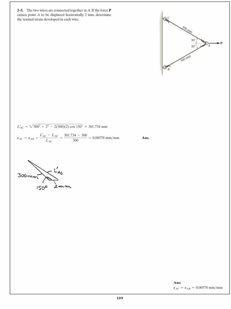
109
Ans.PAC = PAB =
Lœ
AC - LAC
LAC=
301.734 - 300300
= 0.00578 mm>mm
Lœ
AC = 23002+ 22
- 2(300)(2) cos 150° = 301.734 mm
2–5. The two wires are connected together at A. If the force Pcauses point A to be displaced horizontally 2 mm, determinethe normal strain developed in each wire.
© 2014 Pearson Education, Inc., Upper Saddle River, NJ. All rights reserved. This material is protected under all copyright laws as they currentlyexist. No portion of this material may be reproduced, in any form or by any means, without permission in writing from the publisher.
P30�
30� A
B
C
300 mm
300 mm
Ans:PAC = PAB = 0.00578 mm>mm
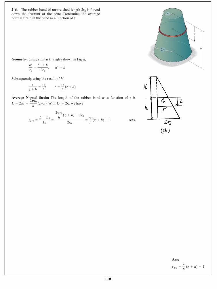
110
Geometry: Using similar triangles shown in Fig. a,
Subsequently, using the result of
Average Normal Strain: The length of the rubber band as a function of z is
With , we have
Ans.Pavg =
L - L0
L0=
2pr0
h (z + h) - 2r0
2r0=
p
h (z + h) - 1
L0 = 2r0L = 2pr =
2pr0
h (z+h).
r =
r0
h (z + h)
rz + h
=
r0
h ;
h¿
h¿ = hh¿
r0=
h¿ + h2r0
;
2–6. The rubber band of unstretched length 2r0 is forceddown the frustum of the cone. Determine the averagenormal strain in the band as a function of z.
© 2014 Pearson Education, Inc., Upper Saddle River, NJ. All rights reserved. This material is protected under all copyright laws as they currentlyexist. No portion of this material may be reproduced, in any form or by any means, without permission in writing from the publisher.
r0
h
z
2r0
Ans:
Pavg =
p
h (z + h) - 1
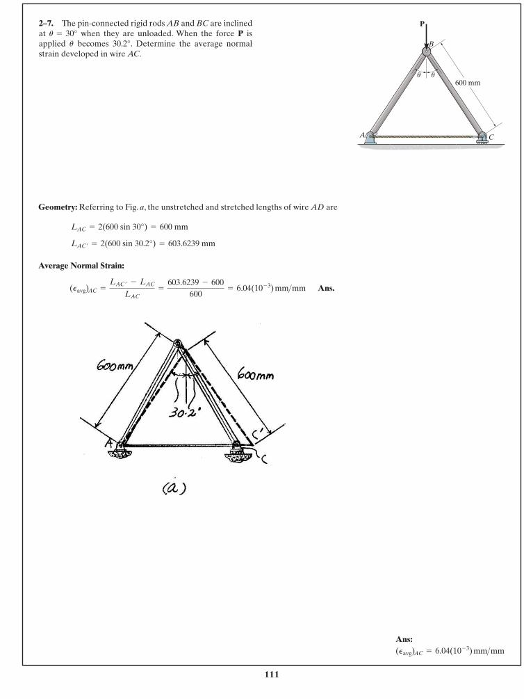
111
Geometry: Referring to Fig. a, the unstretched and stretched lengths of wire AD are
Average Normal Strain:
Ans.(Pavg) AC =
LAC ¿ - LAC
LAC=
603.6239 - 600600
= 6.04(10- 3) mm >mm
LAC ¿ = 2(600 sin 30.2°) = 603.6239 mm
LAC = 2(600 sin 30°) = 600 mm
2–7. The pin-connected rigid rods AB and BC are inclinedat when they are unloaded. When the force P isapplied becomes 30.2°. Determine the average normalstrain developed in wire AC.
u
u = 30°
© 2014 Pearson Education, Inc., Upper Saddle River, NJ. All rights reserved. This material is protected under all copyright laws as they currentlyexist. No portion of this material may be reproduced, in any form or by any means, without permission in writing from the publisher.
P
B
C A
600 mmuu
Ans:(Pavg) AC = 6.04(10- 3) mm >mm
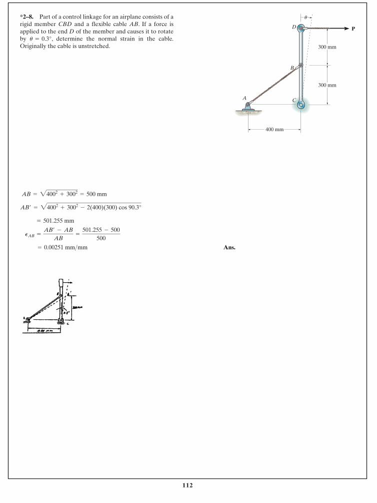
112
Ans. = 0.00251 mm>mm
PAB =
AB¿ - AB
AB=
501.255 - 500500
= 501.255 mm
AB¿ = 24002+ 3002
- 2(400)(300) cos 90.3°
AB = 24002+ 3002
= 500 mm
*2–8. Part of a control linkage for an airplane consists of arigid member CBD and a flexible cable AB. If a force isapplied to the end D of the member and causes it to rotateby , determine the normal strain in the cable.Originally the cable is unstretched.u = 0.3°
© 2014 Pearson Education, Inc., Upper Saddle River, NJ. All rights reserved. This material is protected under all copyright laws as they currentlyexist. No portion of this material may be reproduced, in any form or by any means, without permission in writing from the publisher.
400 mm
300 mm
A
B
D P
300 mm
C
u
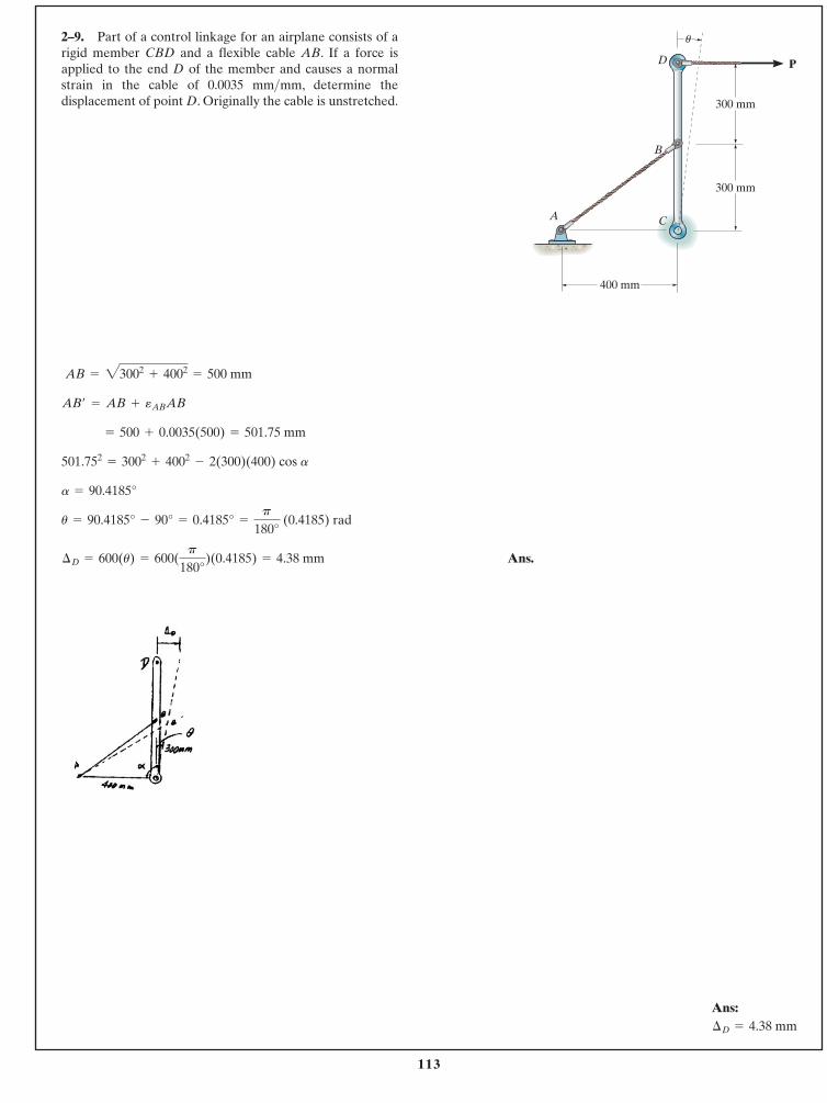
113
Ans.¢D = 600(u) = 600(p
180°)(0.4185) = 4.38 mm
u = 90.4185° - 90° = 0.4185° =
p
180° (0.4185) rad
a = 90.4185°
501.752= 3002
+ 4002- 2(300)(400) cos a
= 500 + 0.0035(500) = 501.75 mm
AB¿ = AB + eABAB
AB = 23002+ 4002
= 500 mm
2–9. Part of a control linkage for an airplane consists of arigid member CBD and a flexible cable AB. If a force isapplied to the end D of the member and causes a normalstrain in the cable of 0.0035 mm mm, determine thedisplacement of point D. Originally the cable is unstretched.
>
© 2014 Pearson Education, Inc., Upper Saddle River, NJ. All rights reserved. This material is protected under all copyright laws as they currentlyexist. No portion of this material may be reproduced, in any form or by any means, without permission in writing from the publisher.
400 mm
300 mm
A
B
D P
300 mm
C
u
Ans:¢D = 4.38 mm
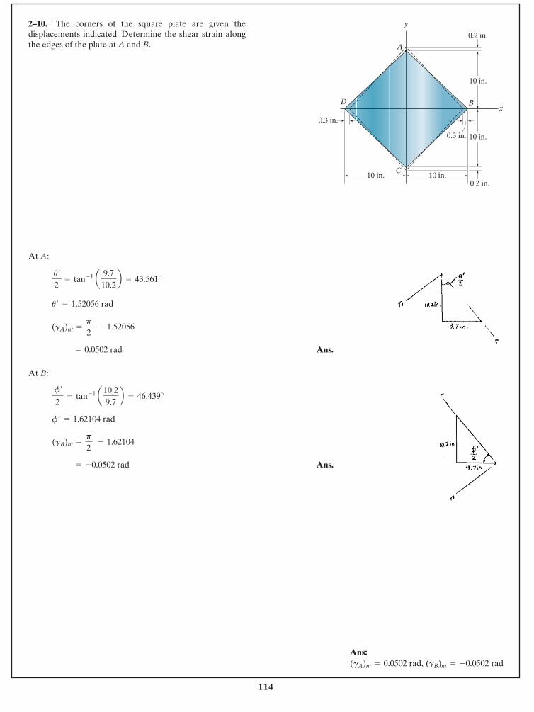
114
At A:
Ans.
At B:
Ans.= -0.0502 rad
(gB)nt =
p
2 - 1.62104
f¿ = 1.62104 rad
f¿
2= tan- 1 a10.2
9.7b = 46.439°
= 0.0502 rad
(gA)nt =
p
2 - 1.52056
u¿ = 1.52056 rad
u¿
2= tan- 1 a 9.7
10.2b = 43.561°
2–10. The corners of the square plate are given thedisplacements indicated. Determine the shear strain alongthe edges of the plate at A and B.
© 2014 Pearson Education, Inc., Upper Saddle River, NJ. All rights reserved. This material is protected under all copyright laws as they currentlyexist. No portion of this material may be reproduced, in any form or by any means, without permission in writing from the publisher.
0.3 in.
0.2 in.
0.3 in.
10 in.10 in.
10 in.
10 in.
0.2 in.
y
x
A
B
C
D
Ans:(gB)nt = -0.0502 rad(gA)nt = 0.0502 rad,
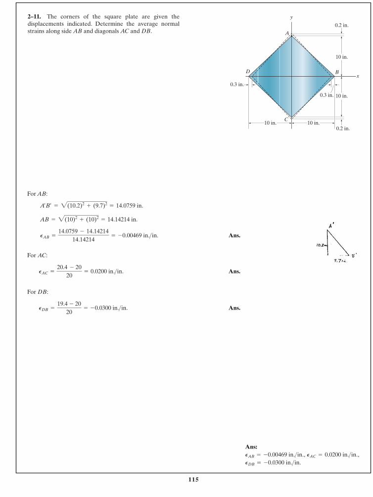
115
For AB:
Ans.
For AC:
Ans.
For DB:
Ans.PDB =
19.4 - 2020
= -0.0300 in. >in.
PAC =
20.4 - 2020
= 0.0200 in. >in.
PAB =
14.0759 - 14.1421414.14214
= -0.00469 in. >in.
AB = 2(10)2+ (10)2
= 14.14214 in.
A¿B¿ = 2(10.2)2+ (9.7)2
= 14.0759 in.
2–11. The corners of the square plate are given thedisplacements indicated. Determine the average normalstrains along side AB and diagonals AC and DB.
© 2014 Pearson Education, Inc., Upper Saddle River, NJ. All rights reserved. This material is protected under all copyright laws as they currentlyexist. No portion of this material may be reproduced, in any form or by any means, without permission in writing from the publisher.
0.3 in.
0.2 in.
0.3 in.
10 in.10 in.
10 in.
10 in.
0.2 in.
y
x
A
B
C
D
Ans:
PDB = -0.0300 in. >in.PAC = 0.0200 in. >in.,PAB = -0.00469 in. >in.,
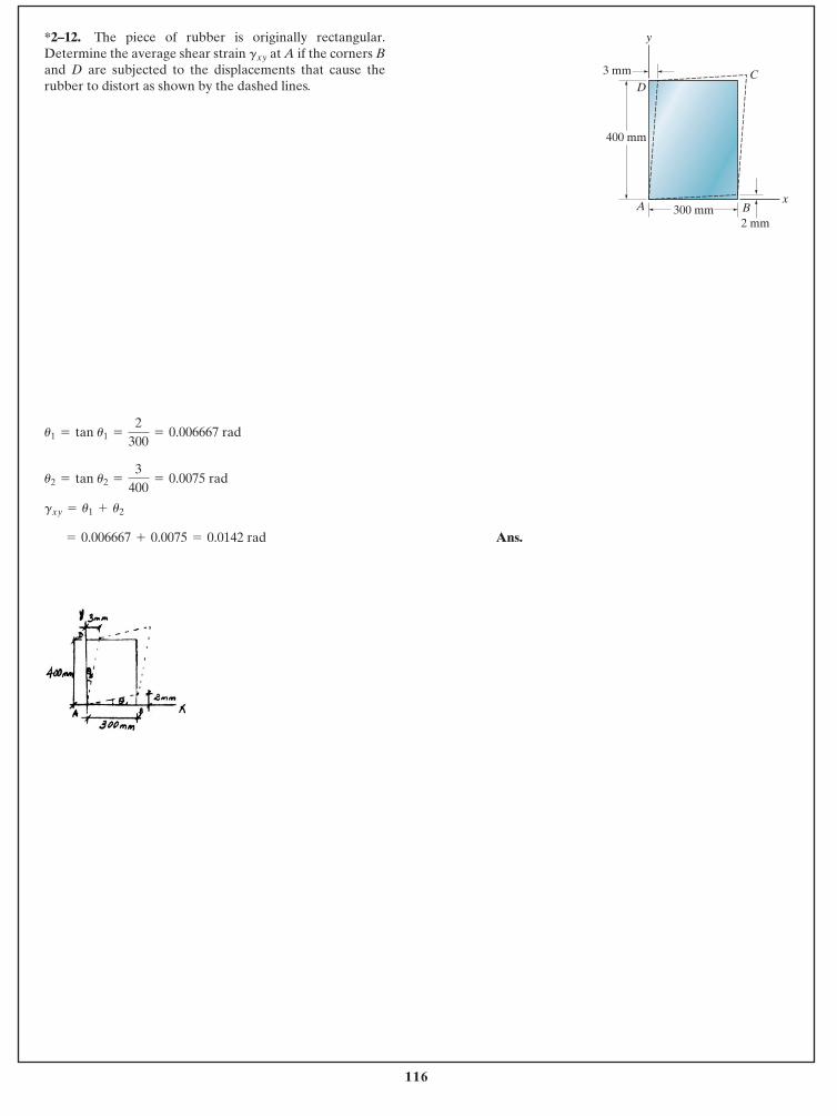
116
Ans. = 0.006667 + 0.0075 = 0.0142 rad
gxy = u1 + u2
u2 = tan u2 =
3400
= 0.0075 rad
*2–12. The piece of rubber is originally rectangular.Determine the average shear strain at A if the corners Band D are subjected to the displacements that cause therubber to distort as shown by the dashed lines.
gxy
© 2014 Pearson Education, Inc., Upper Saddle River, NJ. All rights reserved. This material is protected under all copyright laws as they currentlyexist. No portion of this material may be reproduced, in any form or by any means, without permission in writing from the publisher.
300 mm
400 mm
D
A
y
x
3 mm
2 mmB
C
u1 = tan u1 =
2300
= 0.006667 rad
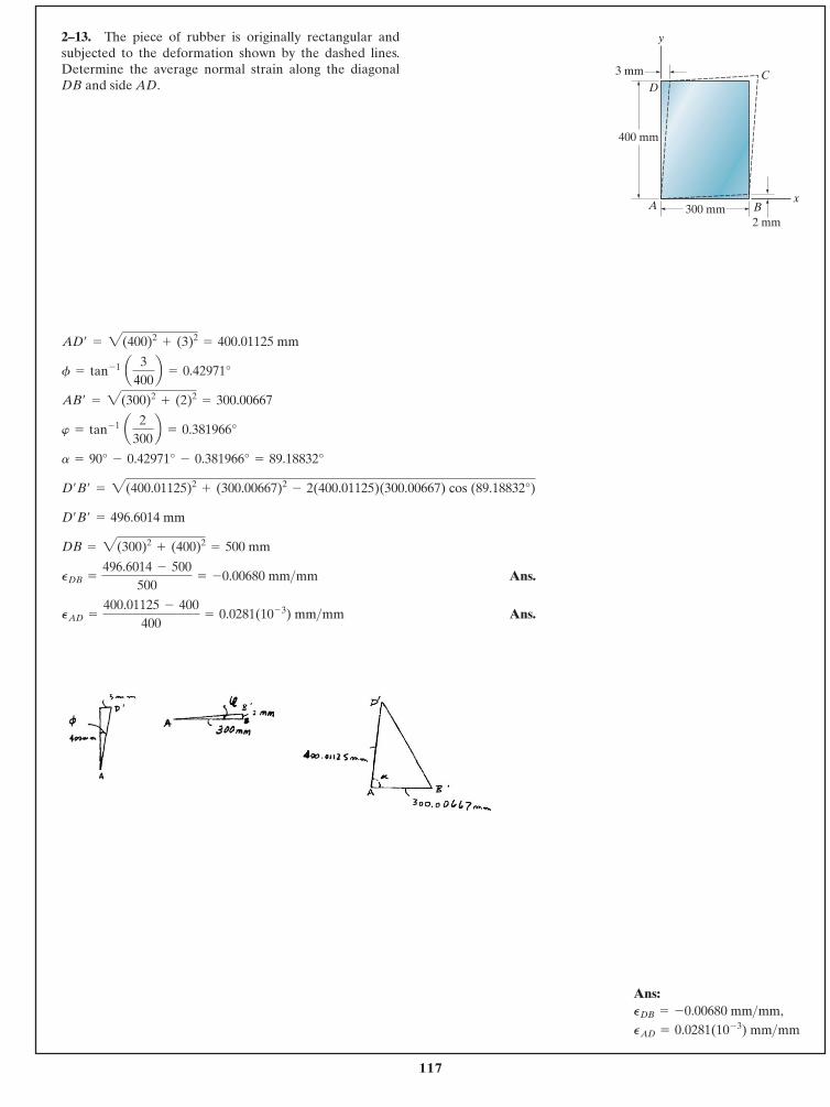
117
Ans.
Ans.PAD =
400.01125 - 400400
= 0.0281(10- 3) mm>mm
PDB =
496.6014 - 500500
= -0.00680 mm>mm
DB = 2(300)2+ (400)2
= 500 mm
D¿B¿ = 496.6014 mm
D¿B¿ = 2(400.01125)2+ (300.00667)2
- 2(400.01125)(300.00667) cos (89.18832°)
a = 90° - 0.42971° - 0.381966° = 89.18832°
w = tan- 1 a 2300b = 0.381966°
AB¿ = 2(300)2+ (2)2
= 300.00667
f = tan- 1 a 3400b = 0.42971°
AD¿ = 2(400)2+ (3)2
= 400.01125 mm
2–13. The piece of rubber is originally rectangular andsubjected to the deformation shown by the dashed lines.Determine the average normal strain along the diagonalDB and side AD.
© 2014 Pearson Education, Inc., Upper Saddle River, NJ. All rights reserved. This material is protected under all copyright laws as they currentlyexist. No portion of this material may be reproduced, in any form or by any means, without permission in writing from the publisher.
300 mm
400 mm
D
A
y
x
3 mm
2 mmB
C
Ans:
PAD = 0.0281(10- 3) mm>mmPDB = -0.00680 mm>mm,
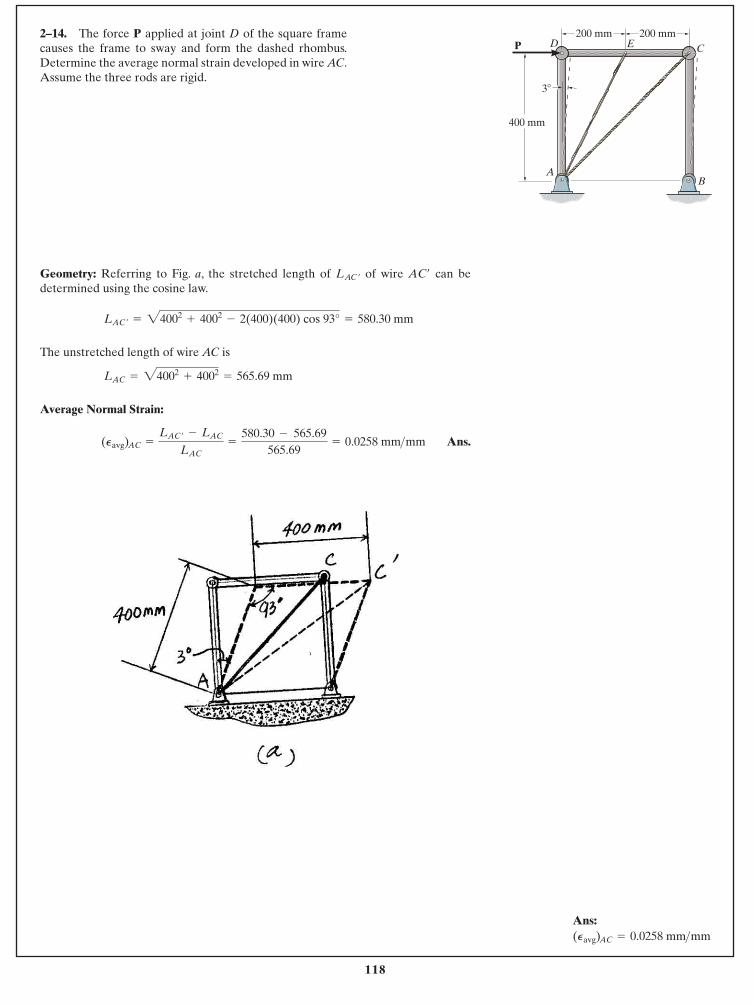
118
Geometry: Referring to Fig. a, the stretched length of of wire can bedetermined using the cosine law.
The unstretched length of wire AC is
Average Normal Strain:
Ans.(Pavg) AC =
LAC ¿ - LAC
LAC=
580.30 - 565.69565.69
= 0.0258 mm >mm
LAC = 24002+ 4002
= 565.69 mm
LAC ¿ = 24002+ 4002
- 2(400)(400) cos 93° = 580.30 mm
AC¿LAC ¿
2–14. The force P applied at joint D of the square framecauses the frame to sway and form the dashed rhombus.Determine the average normal strain developed in wire AC.Assume the three rods are rigid.
© 2014 Pearson Education, Inc., Upper Saddle River, NJ. All rights reserved. This material is protected under all copyright laws as they currentlyexist. No portion of this material may be reproduced, in any form or by any means, without permission in writing from the publisher.
AB
CD E
400 mm
200 mm 200 mm
3�
P
Ans:(Pavg) AC = 0.0258 mm >mm
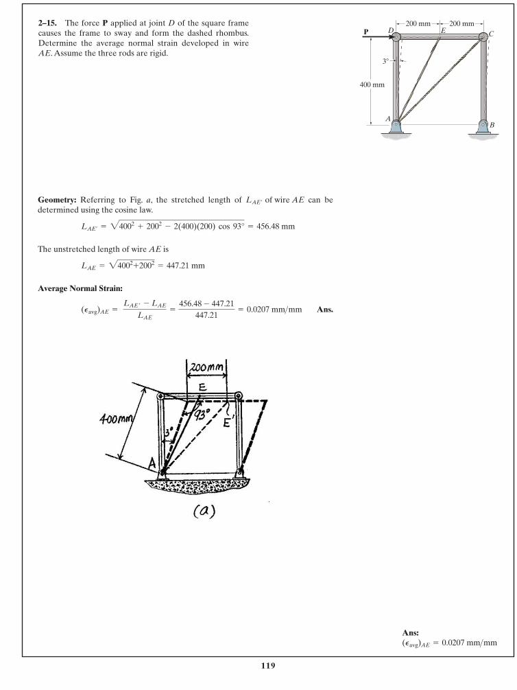
119
Geometry: Referring to Fig. a, the stretched length of can bedetermined using the cosine law.
The unstretched length of wire AE is
Average Normal Strain:
Ans.(Pavg)AE = LAE ¿ - LAE
LAE=
456.48 - 447.21447.21
= 0.0207 mm >mm
LAE = 24002+2002
= 447.21 mm
LAE¿= 24002
+ 2002- 2(400)(200) cos 93° = 456.48 mm
LAE¿ of wire AE
2–15. The force P applied at joint D of the square framecauses the frame to sway and form the dashed rhombus.Determine the average normal strain developed in wireAE. Assume the three rods are rigid.
© 2014 Pearson Education, Inc., Upper Saddle River, NJ. All rights reserved. This material is protected under all copyright laws as they currentlyexist. No portion of this material may be reproduced, in any form or by any means, without permission in writing from the publisher.
AB
CD E
400 mm
200 mm 200 mm
3�
P
Ans:(Pavg)AE = 0.0207 mm >mm
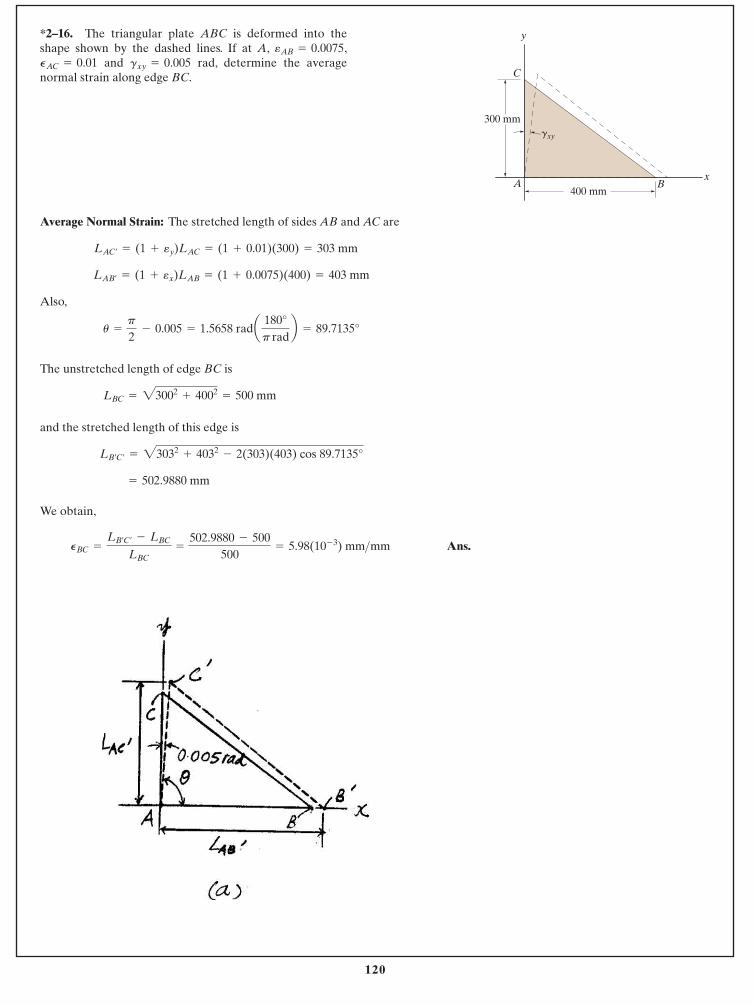
120
Average Normal Strain: The stretched length of sides AB and AC are
Also,
The unstretched length of edge BC is
and the stretched length of this edge is
We obtain,
Ans.PBC =
LB¿C¿- LBC
LBC=
502.9880 - 500500
= 5.98(10- 3) mm>mm
= 502.9880 mm
LB¿C¿= 23032
+ 4032- 2(303)(403) cos 89.7135°
LBC = 23002+ 4002
= 500 mm
u =
p
2 - 0.005 = 1.5658 rada 180°
p radb = 89.7135°
LAB¿= (1 + ex)LAB = (1 + 0.0075)(400) = 403 mm
LAC¿= (1 + ey)LAC = (1 + 0.01)(300) = 303 mm
*2–16. The triangular plate ABC is deformed into theshape shown by the dashed lines. If at A, ,
and rad, determine the averagenormal strain along edge BC.
gxy = 0.005PAC = 0.01eAB = 0.0075
© 2014 Pearson Education, Inc., Upper Saddle River, NJ. All rights reserved. This material is protected under all copyright laws as they currentlyexist. No portion of this material may be reproduced, in any form or by any means, without permission in writing from the publisher.
A
C
B
y
x
300 mm
400 mm
gxy
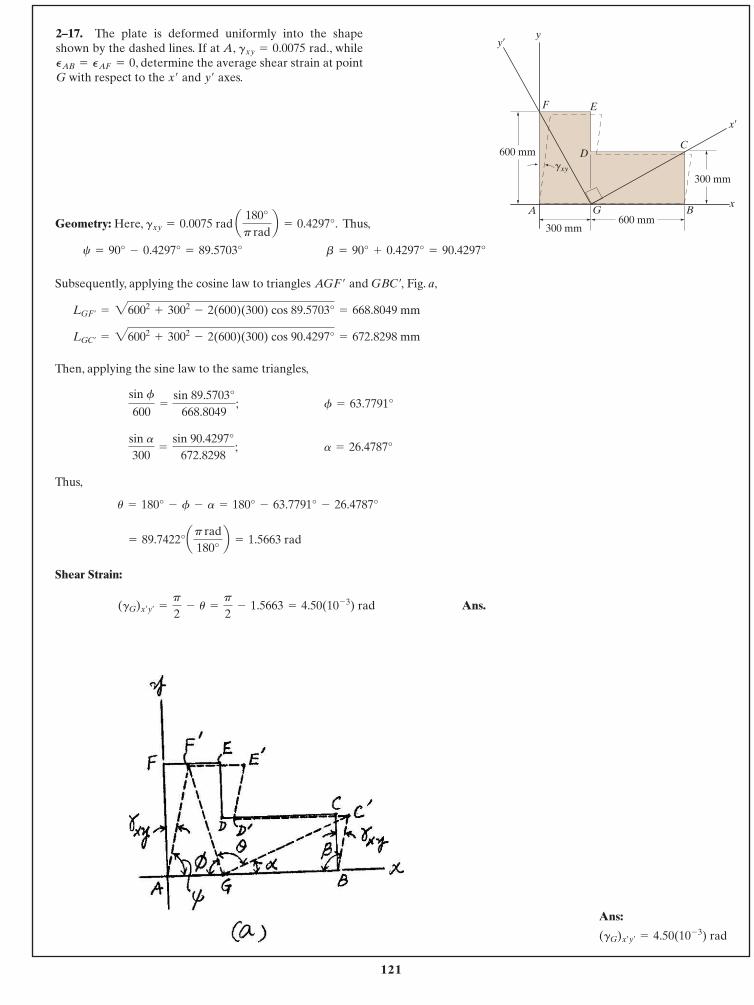
121
Geometry: Here, . Thus,
Subsequently, applying the cosine law to triangles and Fig. a,
Then, applying the sine law to the same triangles,
Thus,
Shear Strain:
Ans.(gG)x¿y¿=
p
2- u =
p
2- 1.5663 = 4.50(10- 3) rad
= 89.7422°ap rad180°
b = 1.5663 rad
u = 180° - f - a = 180° - 63.7791° - 26.4787°
a = 26.4787°sin a300
=
sin 90.4297°672.8298
;
f = 63.7791°sin f
600=
sin 89.5703°668.8049
;
LGC¿= 26002
+ 3002- 2(600)(300) cos 90.4297° = 672.8298 mm
LGF¿= 26002
+ 3002- 2(600)(300) cos 89.5703° = 668.8049 mm
GBC¿,AGF¿
b = 90° + 0.4297° = 90.4297°c = 90° - 0.4297° = 89.5703°
gxy = 0.0075 rad a 180°p rad
b = 0.4297°
2–17. The plate is deformed uniformly into the shapeshown by the dashed lines. If at A, rad., while
, determine the average shear strain at pointG with respect to the and axes.y¿x¿
PAB = PAF = 0gxy = 0.0075
© 2014 Pearson Education, Inc., Upper Saddle River, NJ. All rights reserved. This material is protected under all copyright laws as they currentlyexist. No portion of this material may be reproduced, in any form or by any means, without permission in writing from the publisher.
y y¿
x¿
x
F E
D
G B
C
A
600 mm
300 mm600 mm
300 mmgxy
Ans:
(gG)x¿y¿= 4.50(10- 3) rad
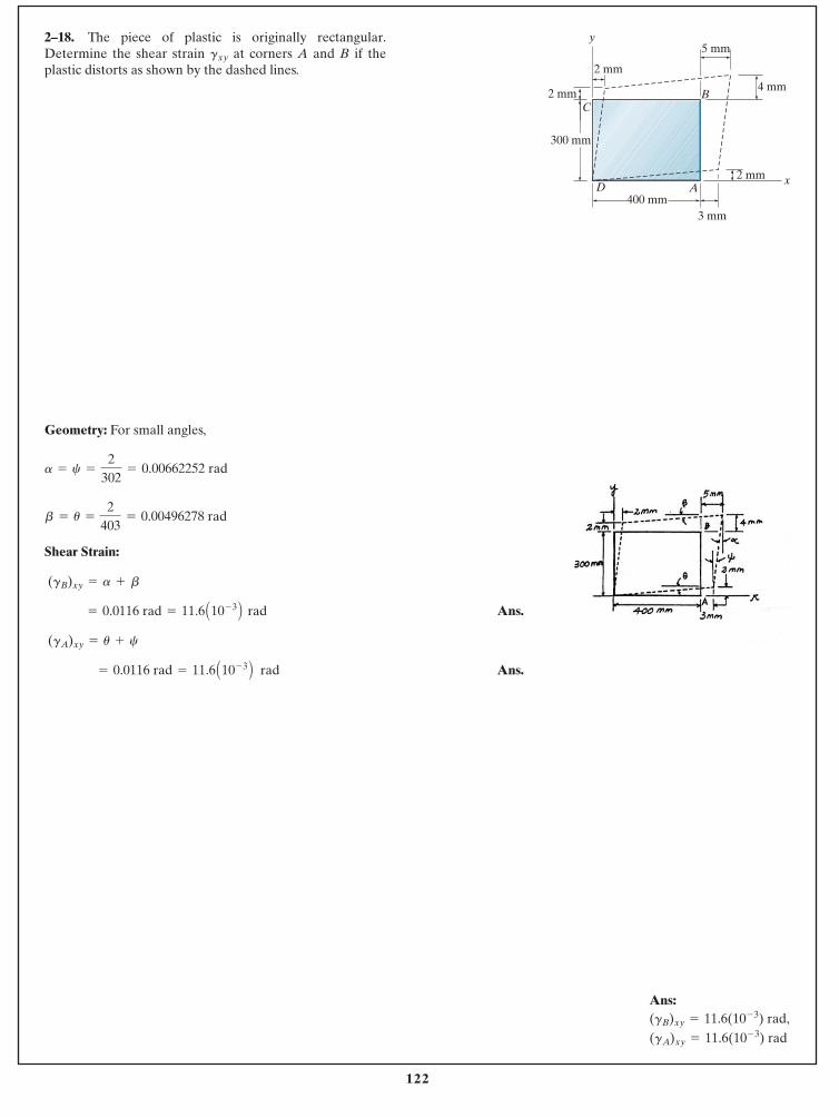
122
Geometry: For small angles,
Shear Strain:
Ans.
Ans. = 0.0116 rad = 11.6 A10- 3 B rad
(gA)xy = u + c
= 0.0116 rad = 11.6 A10- 3 B rad
(gB)xy = a + b
b = u =
2403
= 0.00496278 rad
a = c =
2302
= 0.00662252 rad
2–18. The piece of plastic is originally rectangular.Determine the shear strain at corners A and B if theplastic distorts as shown by the dashed lines.
gxy
© 2014 Pearson Education, Inc., Upper Saddle River, NJ. All rights reserved. This material is protected under all copyright laws as they currentlyexist. No portion of this material may be reproduced, in any form or by any means, without permission in writing from the publisher.
300 mm
400 mmD A
y
x
3 mm
2 mm
B
5 mm
2 mm4 mm
2 mm
C
Ans:
(gA)xy = 11.6(10- 3) rad(gB)xy = 11.6(10- 3) rad,
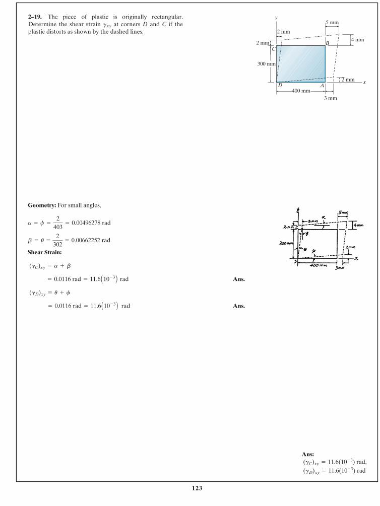
123
Geometry: For small angles,
Shear Strain:
Ans.
Ans. = 0.0116 rad = 11.6 A10- 3 B rad
(gD)xy = u + c
= 0.0116 rad = 11.6 A10- 3 B rad
(gC)xy = a + b
b = u =
2302
= 0.00662252 rad
a = c =
2403
= 0.00496278 rad
2–19. The piece of plastic is originally rectangular.Determine the shear strain at corners D and C if theplastic distorts as shown by the dashed lines.
gxy
© 2014 Pearson Education, Inc., Upper Saddle River, NJ. All rights reserved. This material is protected under all copyright laws as they currentlyexist. No portion of this material may be reproduced, in any form or by any means, without permission in writing from the publisher.
300 mm
400 mmD A
y
x
3 mm
2 mm
B
5 mm
2 mm4 mm
2 mm
C
Ans:
(gD)xy = 11.6(10- 3) rad (gC)xy = 11.6(10- 3) rad,
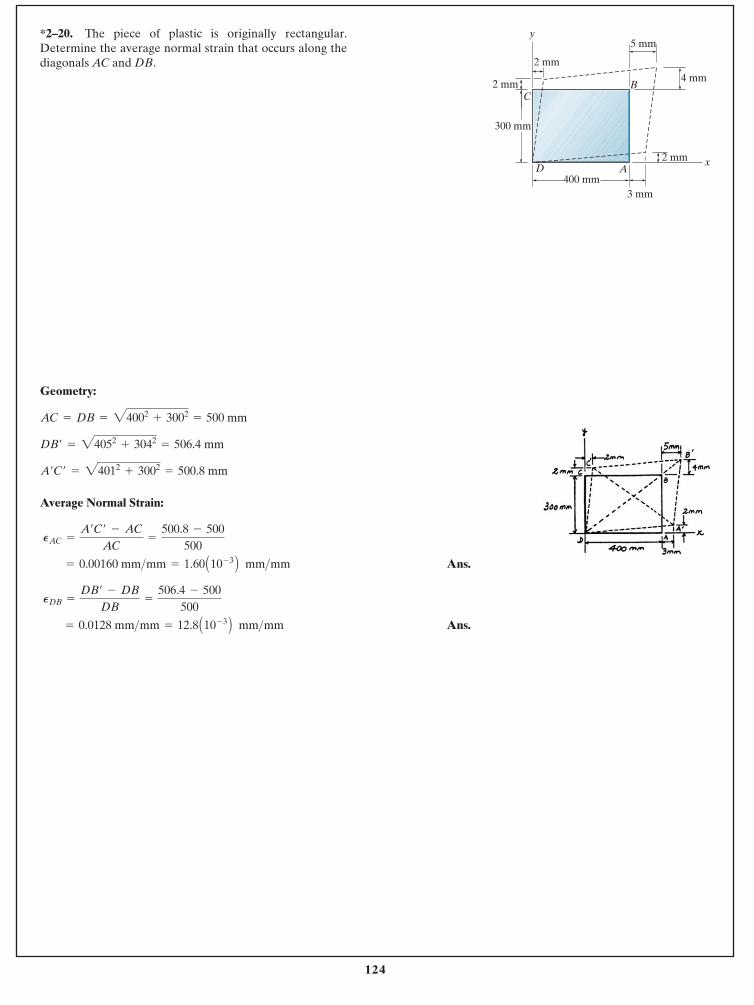
124
Geometry:
Average Normal Strain:
Ans.
Ans. = 0.0128 mm>mm = 12.8 A10- 3 B mm>mm
PDB =
DB¿ - DB
DB=
506.4 - 500500
= 0.00160 mm>mm = 1.60 A10- 3 B mm>mm
PAC =
A¿C¿ - AC
AC=
500.8 - 500500
A¿C¿ = 24012+ 3002
= 500.8 mm
DB¿ = 24052+ 3042
= 506.4 mm
AC = DB = 24002+ 3002
= 500 mm
*2–20. The piece of plastic is originally rectangular.Determine the average normal strain that occurs along thediagonals AC and DB.
© 2014 Pearson Education, Inc., Upper Saddle River, NJ. All rights reserved. This material is protected under all copyright laws as they currentlyexist. No portion of this material may be reproduced, in any form or by any means, without permission in writing from the publisher.
300 mm
400 mmD A
y
x
3 mm
2 mm
B
5 mm
2 mm4 mm
2 mm
C
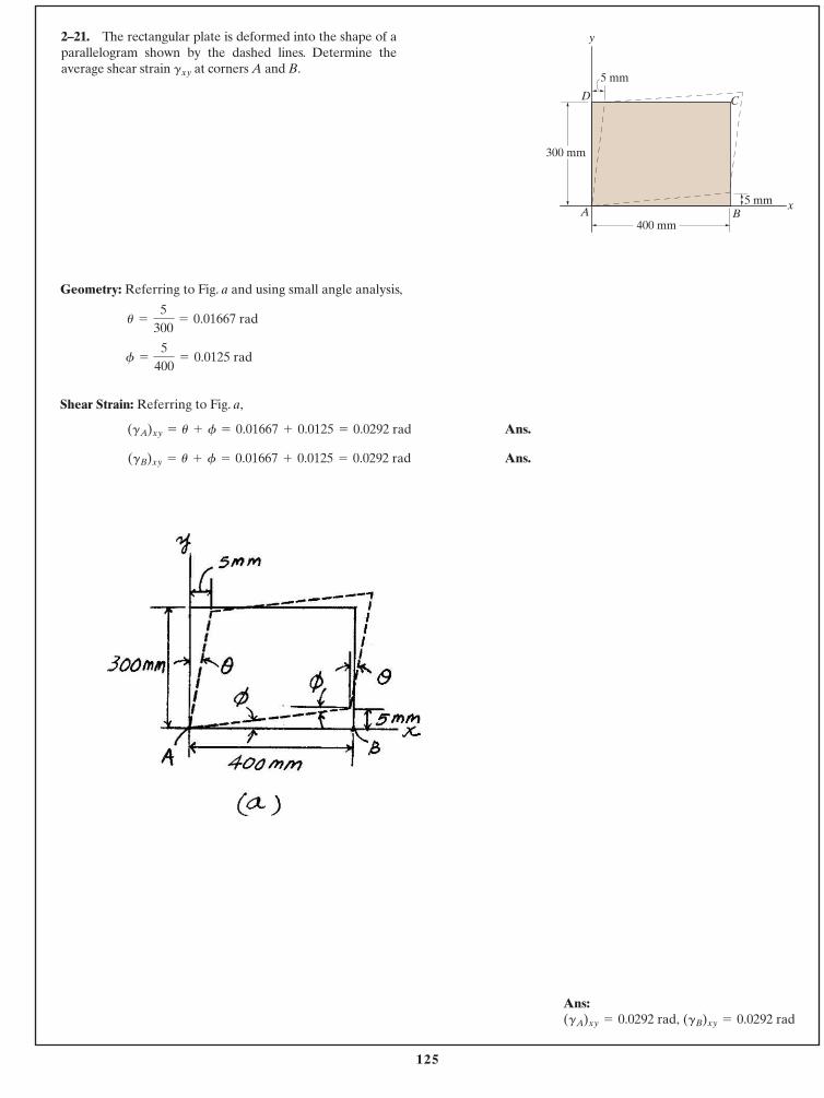
125
Geometry: Referring to Fig. a and using small angle analysis,
Shear Strain: Referring to Fig. a,
Ans.
Ans.(gB)xy = u + f = 0.01667 + 0.0125 = 0.0292 rad
(gA)xy = u + f = 0.01667 + 0.0125 = 0.0292 rad
f =
5400
= 0.0125 rad
u =
5300
= 0.01667 rad
2–21. The rectangular plate is deformed into the shape of aparallelogram shown by the dashed lines. Determine theaverage shear strain at corners A and B.gxy
© 2014 Pearson Education, Inc., Upper Saddle River, NJ. All rights reserved. This material is protected under all copyright laws as they currentlyexist. No portion of this material may be reproduced, in any form or by any means, without permission in writing from the publisher.
y
xA B
D C
300 mm
5 mm
5 mm
400 mm
Ans:(gB)xy = 0.0292 rad(gA)xy = 0.0292 rad,
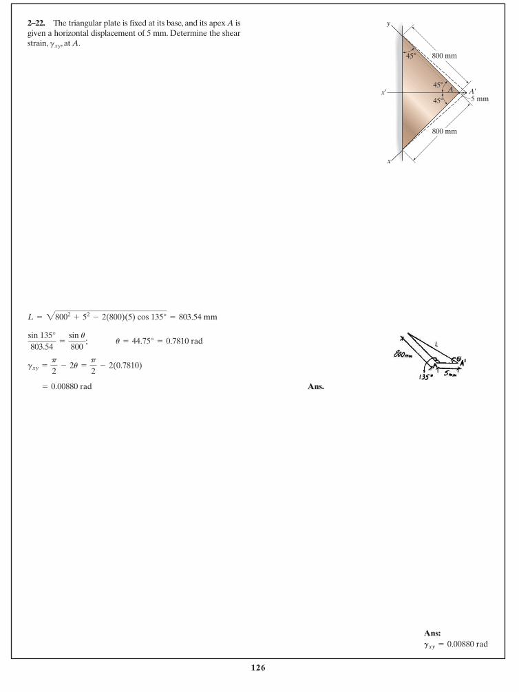
126
Ans.= 0.00880 rad
gxy =
p
2- 2u =
p
2- 2(0.7810)
u = 44.75° = 0.7810 radsin 135°803.54
=
sin u800
;
L = 28002+ 52
- 2(800)(5) cos 135° = 803.54 mm
2–22. The triangular plate is fixed at its base, and its apex A isgiven a horizontal displacement of 5 mm. Determine the shearstrain, , at A.gxy
© 2014 Pearson Education, Inc., Upper Saddle River, NJ. All rights reserved. This material is protected under all copyright laws as they currentlyexist. No portion of this material may be reproduced, in any form or by any means, without permission in writing from the publisher.
800 mm
800 mm
x
x¿
y
A¿
5 mm
45�
45�
45�
A
Ans:gxy = 0.00880 rad
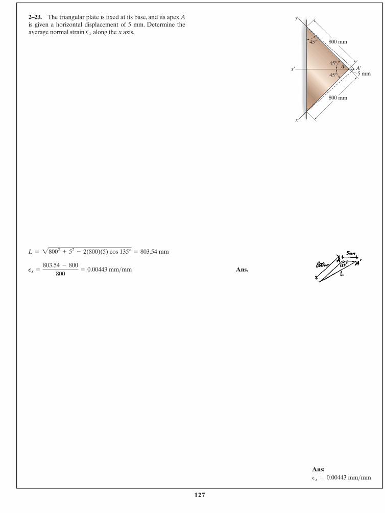
127
Ans.Px =
803.54 - 800800
= 0.00443 mm>mm
L = 28002+ 52
- 2(800)(5) cos 135° = 803.54 mm
2–23. The triangular plate is fixed at its base, and its apex Ais given a horizontal displacement of 5 mm. Determine theaverage normal strain along the axis.xPx
© 2014 Pearson Education, Inc., Upper Saddle River, NJ. All rights reserved. This material is protected under all copyright laws as they currentlyexist. No portion of this material may be reproduced, in any form or by any means, without permission in writing from the publisher.
800 mm
800 mm
x
x¿
y
A¿
5 mm
45�
45�
45�
A
Ans:Px = 0.00443 mm>mm
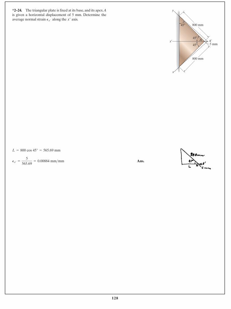
128
Ans.Px¿=
5565.69
= 0.00884 mm>mm
L = 800 cos 45° = 565.69 mm
*2–24. The triangular plate is fixed at its base, and its apex Ais given a horizontal displacement of 5 mm. Determine theaverage normal strain along the axis.x¿Px¿
© 2014 Pearson Education, Inc., Upper Saddle River, NJ. All rights reserved. This material is protected under all copyright laws as they currentlyexist. No portion of this material may be reproduced, in any form or by any means, without permission in writing from the publisher.
800 mm
800 mm
x
x¿
y
A¿
5 mm
45�
45�
45�
A
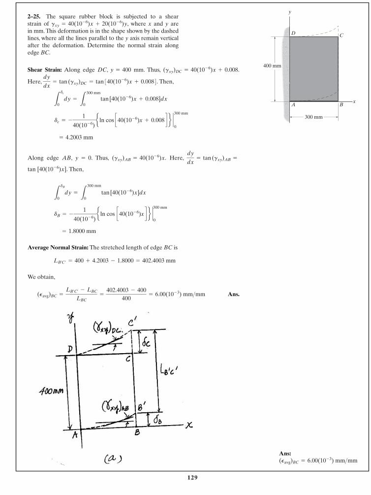
129
Shear Strain: Along edge DC, y = 400 mm. Thus,
Here, Then,
Along edge AB, y = 0. Thus, Here,
Then,
Average Normal Strain: The stretched length of edge BC is
We obtain,
Ans.(Pavg)BC =
LB¿C¿- LBC
LBC=
402.4003 - 400400
= 6.00(10- 3) mm>mm
LB¿C¿= 400 + 4.2003 - 1.8000 = 402.4003 mm
= 1.8000 mm
dB = -
1
40(10- 6)e ln cos c40(10- 6)x d f `300 mm
0
L
dB
0dy =
L
300 mm
0tan [40(10- 6)x]dx
tan [40(10- 6)x].
dy
dx= tan (gxy)AB =(gxy)AB = 40(10- 6)x.
= 4.2003 mm
dc = -
1
40(10- 6)e ln cos c40(10- 6)x + 0.008 d f `
0
300 mm
L
dc
0dy =
L
300 mm
0tan [40(10- 6)x + 0.008]dx
dy
dx= tan (gxy)DC = tan 340(10- 6)x + 0.0084.
(gxy)DC = 40(10- 6)x + 0.008.
2–25. The square rubber block is subjected to a shear strain of , where x and y are in mm. This deformation is in the shape shown by the dashedlines, where all the lines parallel to the y axis remain verticalafter the deformation. Determine the normal strain along edge BC.
gxy = 40(10- 6)x + 20(10- 6)y
© 2014 Pearson Education, Inc., Upper Saddle River, NJ. All rights reserved. This material is protected under all copyright laws as they currentlyexist. No portion of this material may be reproduced, in any form or by any means, without permission in writing from the publisher.
y
x
D C
A B
400 mm
300 mm
Ans:(Pavg)BC = 6.00(10- 3) mm>mm
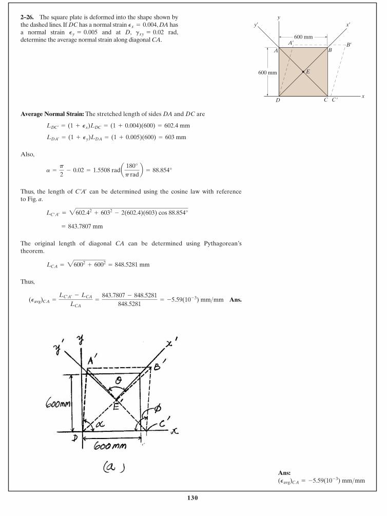
130
Average Normal Strain: The stretched length of sides DA and DC are
Also,
Thus, the length of can be determined using the cosine law with reference to Fig. a.
The original length of diagonal CA can be determined using Pythagorean’stheorem.
Thus,
Ans.(Pavg)CA =
LC¿A¿- LCA
LCA=
843.7807 - 848.5281848.5281
= -5.59(10- 3) mm>mm
LCA = 26002+ 6002
= 848.5281 mm
= 843.7807 mm
LC¿A¿= 2602.42
+ 6032- 2(602.4)(603) cos 88.854°
C¿A¿
a =
p
2- 0.02 = 1.5508 rada 180°
p radb = 88.854°
LDA¿= (1 + Py)LDA = (1 + 0.005)(600) = 603 mm
LDC¿= (1 + Px)LDC = (1 + 0.004)(600) = 602.4 mm
2–26. The square plate is deformed into the shape shown bythe dashed lines. If DC has a normal strain , DA hasa normal strain and at D, rad,determine the average normal strain along diagonal CA.
gxy = 0.02Py = 0.005Px = 0.004
© 2014 Pearson Education, Inc., Upper Saddle River, NJ. All rights reserved. This material is protected under all copyright laws as they currentlyexist. No portion of this material may be reproduced, in any form or by any means, without permission in writing from the publisher.
y y¿ x¿
x
E
AA¿
BB¿
D C C ¿
600 mm
600 mm
Ans:(Pavg)CA = -5.59(10- 3) mm>mm
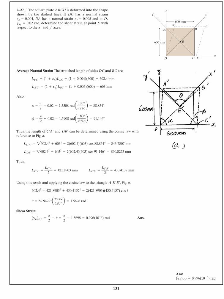
131
Average Normal Strain: The stretched length of sides DC and BC are
Also,
Thus, the length of and can be determined using the cosine law withreference to Fig. a.
Thus,
Using this result and applying the cosine law to the triangle , Fig. a,
Shear Strain:
Ans.(gE)x¿y¿=
p
2- u =
p
2- 1.5698 = 0.996(10- 3) rad
u = 89.9429°ap rad180°
b = 1.5698 rad
602.42= 421.89032
+ 430.41372- 2(421.8903)(430.4137) cos u
A¿E¿B¿
LE¿B¿=
LDB¿
2= 430.4137 mmLE¿A¿
=
LC¿A¿
2= 421.8903 mm
LDB¿= 2602.42
+ 6032- 2(602.4)(603) cos 91.146° = 860.8273 mm
LC¿A¿= 2602.42
+ 6032- 2(602.4)(603) cos 88.854° = 843.7807 mm
DB¿C¿A¿
f =
p
2+ 0.02 = 1.5908 rada 180°
p radb = 91.146°
a =
p
2- 0.02 = 1.5508 rada 180°
p radb = 88.854°
LB¿C¿= (1 + Py)LBC = (1 + 0.005)(600) = 603 mm
LDC¿= (1 + Px)LDC = (1 + 0.004)(600) = 602.4 mm
2–27. The square plate ABCD is deformed into the shapeshown by the dashed lines. If DC has a normal strain
, DA has a normal strain and at D,rad, determine the shear strain at point E with
respect to the and axes.y¿x¿
gxy = 0.02Py = 0.005Px = 0.004
© 2014 Pearson Education, Inc., Upper Saddle River, NJ. All rights reserved. This material is protected under all copyright laws as they currentlyexist. No portion of this material may be reproduced, in any form or by any means, without permission in writing from the publisher.
y y¿ x¿
x
E
AA¿
BB¿
D C C ¿
600 mm
600 mm
Ans:(gE)x¿y¿
= 0.996(10- 3) rad
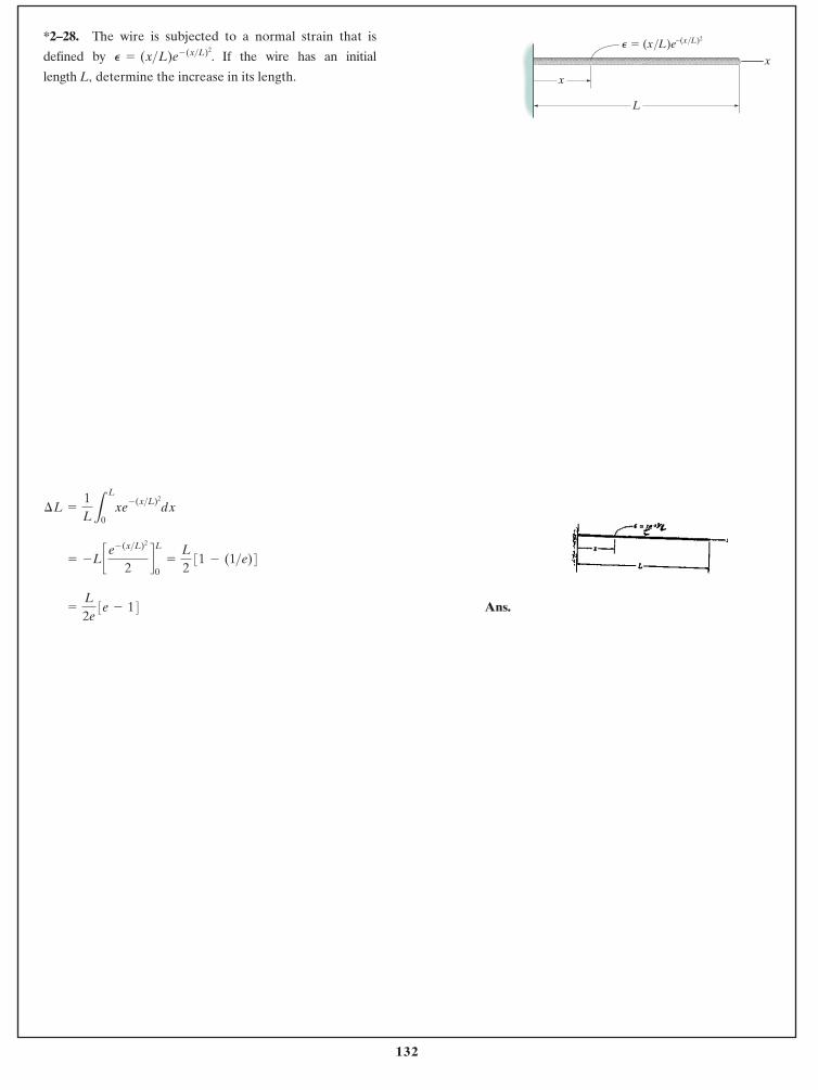
132
Ans.=
L
2e 3e - 14
= -L c e- (x>L)2
2dL
0=
L
2 31 - (1>e)4
¢L =
1LL
L
0xe- (x>L)2
dx
*2–28. The wire is subjected to a normal strain that is
defined by . If the wire has an initial
length L, determine the increase in its length.
P = (x>L)e- (x>L)2
© 2014 Pearson Education, Inc., Upper Saddle River, NJ. All rights reserved. This material is protected under all copyright laws as they currentlyexist. No portion of this material may be reproduced, in any form or by any means, without permission in writing from the publisher.
x
x
L
P � (x/L)e–(x/L)2
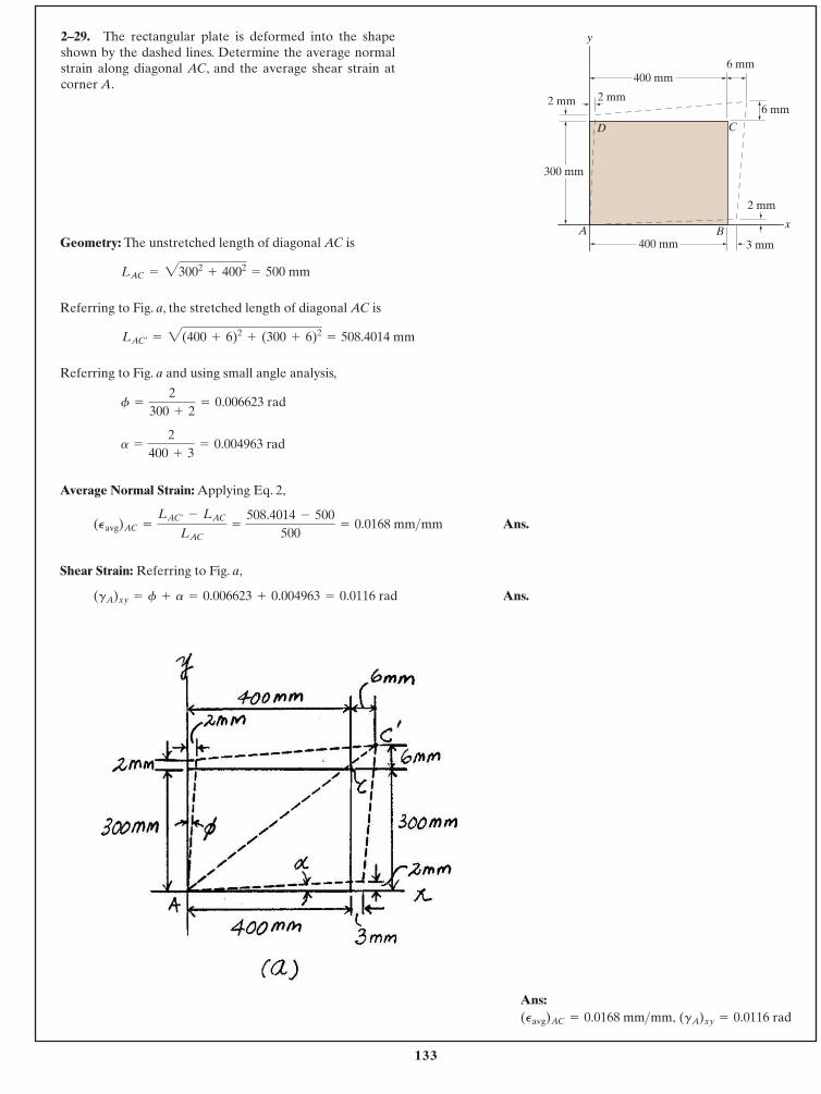
133
Geometry: The unstretched length of diagonal AC is
Referring to Fig. a, the stretched length of diagonal AC is
Referring to Fig. a and using small angle analysis,
Average Normal Strain: Applying Eq. 2,
Ans.
Shear Strain: Referring to Fig. a,
Ans.(gA)xy = f + a = 0.006623 + 0.004963 = 0.0116 rad
(Pavg)AC =
LAC¿- LAC
LAC=
508.4014 - 500500
= 0.0168 mm>mm
a =
2400 + 3
= 0.004963 rad
f =
2300 + 2
= 0.006623 rad
LAC¿= 2(400 + 6)2
+ (300 + 6)2= 508.4014 mm
LAC = 23002+ 4002
= 500 mm
2–29. The rectangular plate is deformed into the shapeshown by the dashed lines. Determine the average normalstrain along diagonal AC, and the average shear strain atcorner A.
© 2014 Pearson Education, Inc., Upper Saddle River, NJ. All rights reserved. This material is protected under all copyright laws as they currentlyexist. No portion of this material may be reproduced, in any form or by any means, without permission in writing from the publisher.
y
xA B
D C
300 mm
400 mm6 mm
6 mm
2 mm
2 mm 2 mm
3 mm400 mm
Ans:(gA)xy = 0.0116 rad(Pavg)AC = 0.0168 mm>mm,
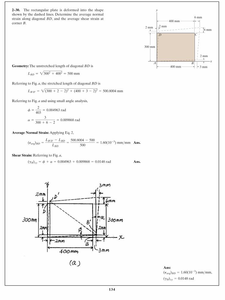
134
Geometry: The unstretched length of diagonal BD is
Referring to Fig. a, the stretched length of diagonal BD is
Referring to Fig. a and using small angle analysis,
Average Normal Strain: Applying Eq. 2,
Ans.
Shear Strain: Referring to Fig. a,
Ans.(gB)xy = f + a = 0.004963 + 0.009868 = 0.0148 rad
(Pavg)BD =
LB¿D¿- LBD
LBD=
500.8004 - 500500
= 1.60(10- 3) mm>mm
a =
3300 + 6 - 2
= 0.009868 rad
f =
2403
= 0.004963 rad
LB¿D¿= 2(300 + 2 - 2)2
+ (400 + 3 - 2)2= 500.8004 mm
LBD = 23002+ 4002
= 500 mm
2–30. The rectangular plate is deformed into the shapeshown by the dashed lines. Determine the average normalstrain along diagonal BD, and the average shear strain atcorner B.
© 2014 Pearson Education, Inc., Upper Saddle River, NJ. All rights reserved. This material is protected under all copyright laws as they currentlyexist. No portion of this material may be reproduced, in any form or by any means, without permission in writing from the publisher.
y
xA B
D C
300 mm
400 mm6 mm
6 mm
2 mm
2 mm 2 mm
3 mm400 mm
Ans:
(gB)xy = 0.0148 rad
(Pavg)BD = 1.60(10- 3) mm>mm,
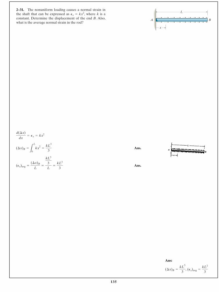
135
Ans.
Ans.(Px)avg =
(¢x)B
L=
kL3
3L
=
kL2
3
(¢x)B =
L
L
0kx2
=
kL3
3
d(¢x)
dx= Px = kx2
2–31. The nonuniform loading causes a normal strain inthe shaft that can be expressed as , where k is aconstant. Determine the displacement of the end B. Also,what is the average normal strain in the rod?
Px = kx2
© 2014 Pearson Education, Inc., Upper Saddle River, NJ. All rights reserved. This material is protected under all copyright laws as they currentlyexist. No portion of this material may be reproduced, in any form or by any means, without permission in writing from the publisher.
A B
L
x
Ans:
(Px)avg =
kL2
3(¢x)B =
kL3
3,
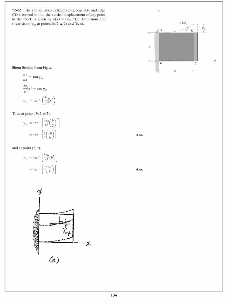
136
Shear Strain: From Fig. a,
Thus, at point (b 2, a 2),
Ans.
and at point (b, a),
Ans.= tan- 1 c3av0
bb d
gxy = tan- 1 c3v0
b3 (b2) d
= tan- 1 c34av0
bb d
gxy = tan- 1 c3v0
b3 ab2b2 d
>>
gxy = tan- 1a 3v0
b3 x2b
3v0
b3 x2= tan gxy
dv
dx= tan gxy
*2–32 The rubber block is fixed along edge AB, and edgeCD is moved so that the vertical displacement of any pointin the block is given by . Determine theshear strain at points and .(b, a)(b>2, a>2)gxy
v(x) = (v0>b3)x3
© 2014 Pearson Education, Inc., Upper Saddle River, NJ. All rights reserved. This material is protected under all copyright laws as they currentlyexist. No portion of this material may be reproduced, in any form or by any means, without permission in writing from the publisher.
y
x
b
a
D
CB
Av0
v (x)

137
Geometry:
Average Normal Strain:
Neglecting higher terms and
Using the binomial theorem:
PAB = B1 +
2(vB sin u - uA cos u)
LR
12
- 1
v2BuA
2
=
A1 +
uA2
+ v2B
L2 +
2(vB sin u - uA cos u)L
- 1
PAB =
LA¿B¿- L
L
= 2L2+ uA
2+ vB
2+ 2L(vB sin u - uA cos u)
LA¿B¿= 2(L cos u - uA)2
+ (L sin u + vB)2
2–33. The fiber AB has a length L and orientation . If itsends A and B undergo very small displacements and ,respectively, determine the normal strain in the fiber whenit is in position .A¿B¿
vBuA
u
© 2014 Pearson Education, Inc., Upper Saddle River, NJ. All rights reserved. This material is protected under all copyright laws as they currentlyexist. No portion of this material may be reproduced, in any form or by any means, without permission in writing from the publisher.
PAB = 1 +
12¢2vB sin u
L-
2uA cos u
L≤ + . . . - 1
Ans. =
vB sin u
L-
uA cos u
L
A
y
x
B¿
BvB
uA A¿
Lu
Ans.
PAB =
vB sin u
L-
uA cos u
L
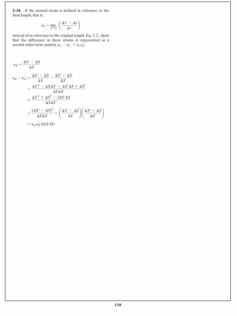
138
(Q.E.D)= PA PBœ
=
(¢S¿ - ¢S)2
¢S¢S¿
= ¢¢S¿ - ¢S
¢S≤ ¢¢S¿ - ¢S
¢S¿
≤
=
¢S¿2
+ ¢S2- 2¢S¿¢S
¢S¢S¿
=
¢S¿2
- ¢S¢S¿ - ¢S¿¢S + ¢S2
¢S¢S¿
PB - PAœ
=
¢S¿ - ¢S
¢S-
¢S¿ - ¢S
¢S¿
PB =
¢S¿ - ¢S
¢S
2–34. If the normal strain is defined in reference to thefinal length, that is,
instead of in reference to the original length, Eq. 2–2 , showthat the difference in these strains is represented as asecond-order term, namely, Pn - Pn¿ = Pn Pn¿ .
P¿n = limp:p¿
a¢s¿ - ¢s
¢s¿
b
© 2014 Pearson Education, Inc., Upper Saddle River, NJ. All rights reserved. This material is protected under all copyright laws as they currentlyexist. No portion of this material may be reproduced, in any form or by any means, without permission in writing from the publisher.
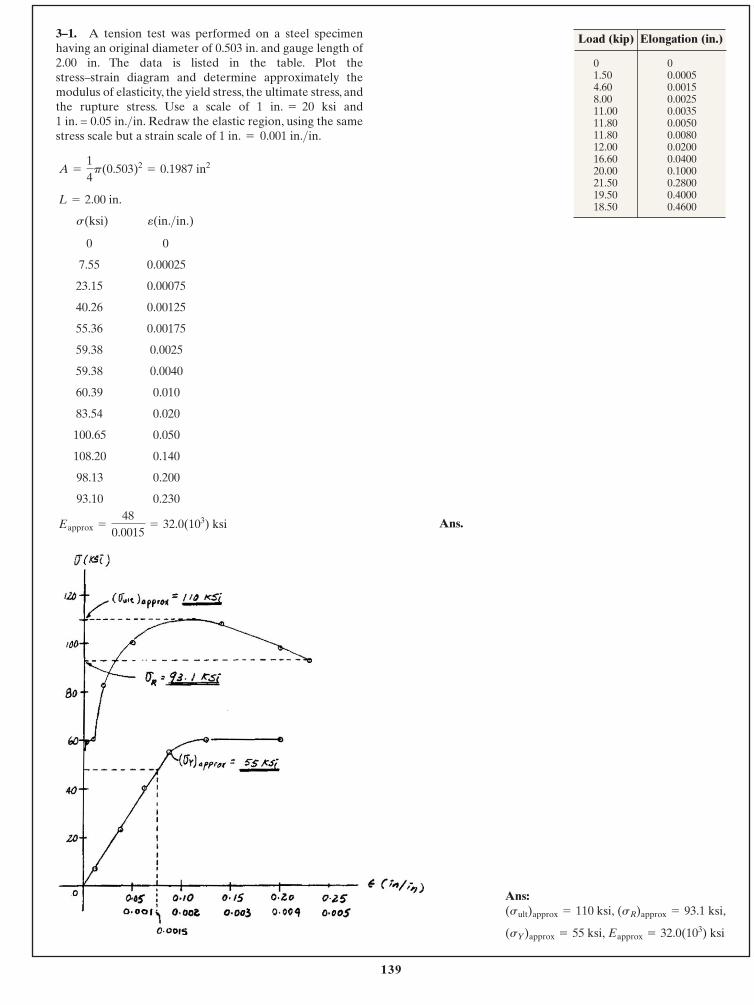
139
© 2014 Pearson Education, Inc., Upper Saddle River, NJ. All rights reserved. This material is protected under all copyright laws as they currentlyexist. No portion of this material may be reproduced, in any form or by any means, without permission in writing from the publisher.
3–1. A tension test was performed on a steel specimenhaving an original diameter of 0.503 in. and gauge length of2.00 in. The data is listed in the table. Plot the stress–strain diagram and determine approximately themodulus of elasticity, the yield stress, the ultimate stress, andthe rupture stress. Use a scale of 1 in. 20 ksi and 1 in. = 0.05 in. in. Redraw the elastic region, using the samestress scale but a strain scale of 1 in. 0.001 in. in.>=
>=
Ans:
(sY)approx = 55 ksi, Eapprox = 32.0(103) ksi
(sult)approx = 110 ksi, (sR)approx = 93.1 ksi,
0 0
7.55 0.00025
23.15 0.00075
40.26 0.00125
55.36 0.00175
59.38 0.0025
59.38 0.0040
60.39 0.010
83.54 0.020
100.65 0.050
108.20 0.140
98.13 0.200
93.10 0.230
Eapprox =
480.0015
= 32.0(103) ksi
e(in.>in.)s(ksi)
L = 2.00 in.
A =
14
p(0.503)2= 0.1987 in2
01.504.608.0011.0011.8011.8012.0016.6020.0021.5019.5018.50
00.00050.00150.00250.00350.00500.00800.02000.04000.10000.28000.40000.4600
Load (kip) Elongation (in.)
Ans.
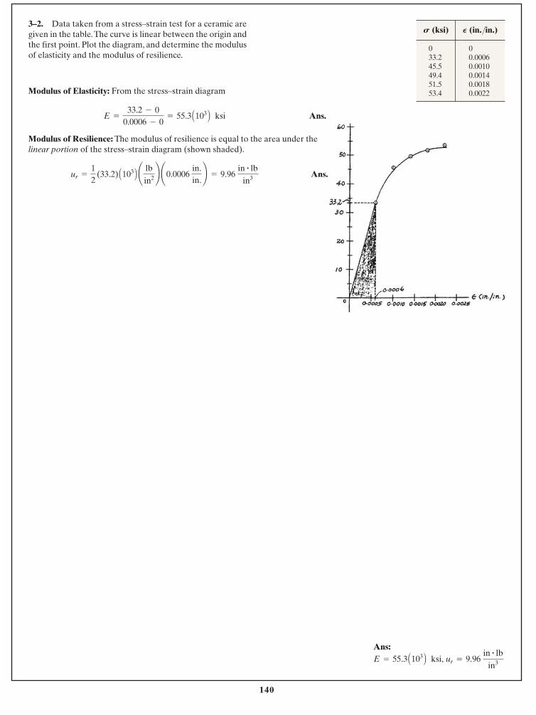
140
© 2014 Pearson Education, Inc., Upper Saddle River, NJ. All rights reserved. This material is protected under all copyright laws as they currentlyexist. No portion of this material may be reproduced, in any form or by any means, without permission in writing from the publisher.
Ans:ur = 9.96
in # lbin3E = 55.3 A103 B ksi,
3–2. Data taken from a stress–strain test for a ceramic aregiven in the table.The curve is linear between the origin andthe first point. Plot the diagram, and determine the modulusof elasticity and the modulus of resilience.
033.245.549.451.553.4
00.00060.00100.00140.00180.0022
S (ksi) P (in./in.)
Modulus of Elasticity: From the stress–strain diagram
Ans.
Modulus of Resilience: The modulus of resilience is equal to the area under thelinear portion of the stress–strain diagram (shown shaded).
Ans.ur =
12
(33.2) A103 B ¢ lbin2 ≤ ¢0.0006
in.in.≤ = 9.96
in # lbin3
E =
33.2 - 00.0006 - 0
= 55.3 A103 B ksi
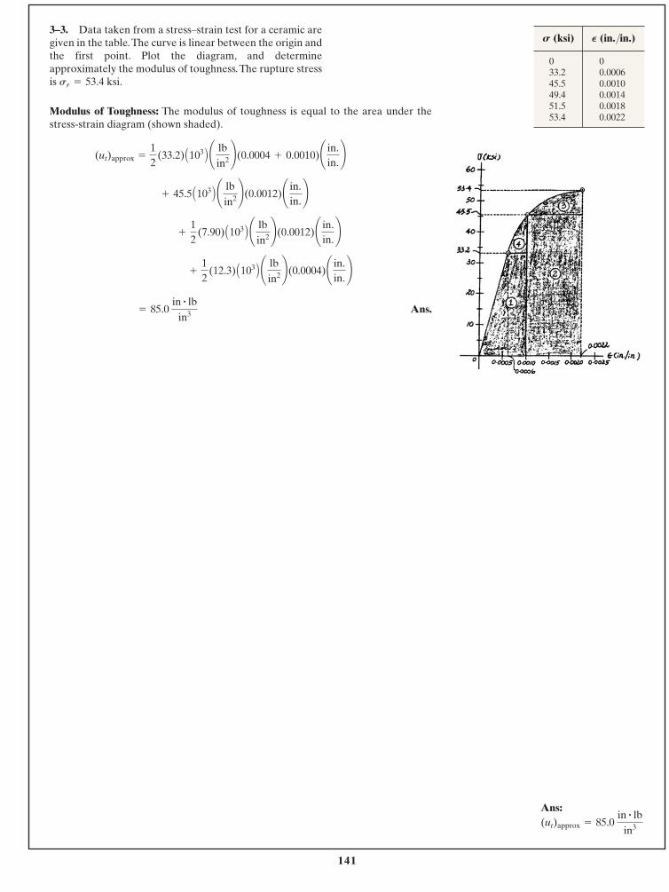
141
© 2014 Pearson Education, Inc., Upper Saddle River, NJ. All rights reserved. This material is protected under all copyright laws as they currentlyexist. No portion of this material may be reproduced, in any form or by any means, without permission in writing from the publisher.
Ans:(ut)approx = 85.0
in # lbin3
Modulus of Toughness: The modulus of toughness is equal to the area under thestress-strain diagram (shown shaded).
Ans. = 85.0 in # lb
in3
+
12
(12.3) A103 B ¢ lbin2 ≤(0.0004)¢ in.
in.≤
+
12
(7.90) A103 B ¢ lbin2 ≤(0.0012)¢ in.
in.≤
+ 45.5 A103 B ¢ lbin2 ≤(0.0012)¢ in.
in.≤
(ut)approx =
12
(33.2) A103 B ¢ lbin2 ≤(0.0004 + 0.0010)¢ in.
in.≤
3–3. Data taken from a stress–strain test for a ceramic aregiven in the table.The curve is linear between the origin andthe first point. Plot the diagram, and determineapproximately the modulus of toughness.The rupture stressis sr = 53.4 ksi.
033.245.549.451.553.4
00.00060.00100.00140.00180.0022
S (ksi) P (in./in.)
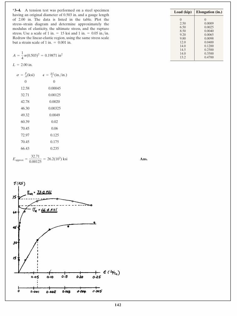
142
© 2014 Pearson Education, Inc., Upper Saddle River, NJ. All rights reserved. This material is protected under all copyright laws as they currentlyexist. No portion of this material may be reproduced, in any form or by any means, without permission in writing from the publisher.
*3–4. A tension test was performed on a steel specimenhaving an original diameter of 0.503 in. and a gauge lengthof 2.00 in. The data is listed in the table. Plot thestress–strain diagram and determine approximately themodulus of elasticity, the ultimate stress, and the rupturestress. Use a scale of 1 in. 15 ksi and 1 in. 0.05 in. in.Redraw the linear-elastic region, using the same stress scalebut a strain scale of 1 in. 0.001 in.=
>==
L = 2.00 in.
A =
14
p(0.503)2= 0.19871 in2
02.506.508.509.209.8012.014.014.514.013.2
00.00090.00250.00400.00650.00980.04000.12000.25000.35000.4700
Load (kip) Elongation (in.)
02.506.508.509.209.8012.014.014.514.013.2
00.00090.00250.00400.00650.00980.04000.12000.25000.35000.4700
Load (kip) Elongation (in.)
0 0
12.58 0.00045
32.71 0.00125
42.78 0.0020
46.30 0.00325
49.32 0.0049
60.39 0.02
70.45 0.06
72.97 0.125
70.45 0.175
66.43 0.235
P =¢LL (in.>in.)s =
PA (ksi)
Ans.Eapprox =
32.710.00125
= 26.2(103) ksi
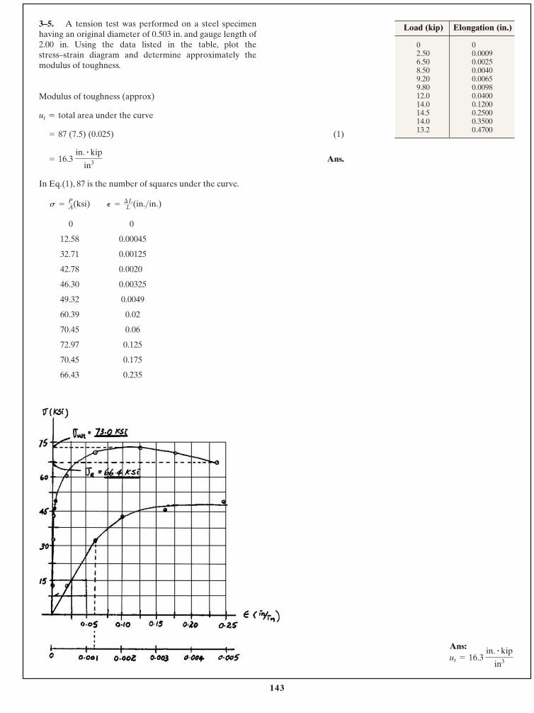
143
© 2014 Pearson Education, Inc., Upper Saddle River, NJ. All rights reserved. This material is protected under all copyright laws as they currentlyexist. No portion of this material may be reproduced, in any form or by any means, without permission in writing from the publisher.
Ans:ut = 16.3
in. # kip
in3
3–5. A tension test was performed on a steel specimenhaving an original diameter of 0.503 in. and gauge length of2.00 in. Using the data listed in the table, plot thestress–strain diagram and determine approximately themodulus of toughness.
Modulus of toughness (approx)
total area under the curve
(1)
Ans.
In Eq.(1), 87 is the number of squares under the curve.
= 16.3 in. # kip
in3
= 87 (7.5) (0.025)
ut =
02.506.508.509.209.8012.014.014.514.013.2
00.00090.00250.00400.00650.00980.04000.12000.25000.35000.4700
Load (kip) Elongation (in.)
02.506.508.509.209.8012.014.014.514.013.2
00.00090.00250.00400.00650.00980.04000.12000.25000.35000.4700
Load (kip) Elongation (in.)
0 0
12.58 0.00045
32.71 0.00125
42.78 0.0020
46.30 0.00325
49.32 0.0049
60.39 0.02
70.45 0.06
72.97 0.125
70.45 0.175
66.43 0.235
P =¢LL (in.>in.)s =
PA(ksi)
144
© 2014 Pearson Education, Inc., Upper Saddle River, NJ. All rights reserved. This material is protected under all copyright laws as they currentlyexist. No portion of this material may be reproduced, in any form or by any means, without permission in writing from the publisher.
Ans:
E = 8.83 A103 B ksi
Normal Stress and Strain: Applying and .
Modulus of Elasticity:
Ans.E =
¢s
¢P
=
9.167 - 2.5460.000750
= 8.83 A103 B ksi
¢P =
0.00912
= 0.000750 in.>in.
s2 =
1.80p4 (0.52)
= 9.167 ksi
s1 =
0.500p4 (0.52)
= 2.546 ksi
e =
dL
Ls =
P
A
3–6. A specimen is originally 1 ft long, has a diameter of0.5 in., and is subjected to a force of 500 lb. When the forceis increased from 500 lb to 1800 lb, the specimen elongates0.009 in. Determine the modulus of elasticity for thematerial if it remains linear elastic.
145
© 2014 Pearson Education, Inc., Upper Saddle River, NJ. All rights reserved. This material is protected under all copyright laws as they currentlyexist. No portion of this material may be reproduced, in any form or by any means, without permission in writing from the publisher.
3–7. A structural member in a nuclear reactor is made of azirconium alloy. If an axial load of 4 kip is to be supportedby the member, determine its required cross-sectional area.Use a factor of safety of 3 relative to yielding. What is theload on the member if it is 3 ft long and its elongation is 0.02 in.? The material haselastic behavior.
Ezr = 14(103) ksi, sY = 57.5 ksi.
Ans:
Allowable Normal Stress:
Ans.
Stress–Strain Relationship: Applying Hooke’s law with
Normal Force: Applying equation .
Ans.P = sA = 7.778 (0.2087) = 1.62 kip
s =
P
A
s = EP = 14 A103 B (0.000555) = 7.778 ksi
P =
d
L=
0.023 (12)
= 0.000555 in.>in.
A = 0.2087 in2= 0.209 in2
19.17 =
4A
sallow =
P
A
sallow = 19.17 ksi
3 =
57.5sallow
F.S. =
sy
sallow
P = 1.62 kip A = 0.209 in2,
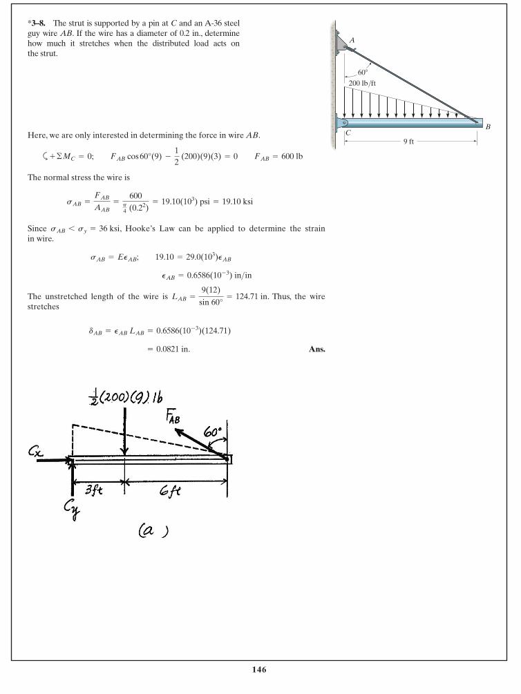
146
© 2014 Pearson Education, Inc., Upper Saddle River, NJ. All rights reserved. This material is protected under all copyright laws as they currentlyexist. No portion of this material may be reproduced, in any form or by any means, without permission in writing from the publisher.
Here, we are only interested in determining the force in wire AB.
a
The normal stress the wire is
Since , Hooke’s Law can be applied to determine the strainin wire.
The unstretched length of the wire is . Thus, the wirestretches
Ans. = 0.0821 in.
dAB = PAB LAB = 0.6586(10- 3)(124.71)
LAB =
9(12)
sin 60°= 124.71 in
PAB = 0.6586(10- 3) in>in sAB = EPAB; 19.10 = 29.0(103)PAB
sAB 6 sy = 36 ksi
sAB =
FAB
AAB=
600p4 (0.22)
= 19.10(103) psi = 19.10 ksi
+ ©MC = 0; FAB cos 60°(9) -
12
(200)(9)(3) = 0 FAB = 600 lb
*3–8. The strut is supported by a pin at C and an A-36 steelguy wire AB. If the wire has a diameter of 0.2 in., determinehow much it stretches when the distributed load acts on the strut.
9 ft
200 lb/ft
C
A
B
60�
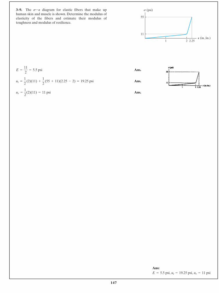
147
© 2014 Pearson Education, Inc., Upper Saddle River, NJ. All rights reserved. This material is protected under all copyright laws as they currentlyexist. No portion of this material may be reproduced, in any form or by any means, without permission in writing from the publisher.
Ans:E = 5.5 psi, ut = 19.25 psi, ur = 11 psi
3–9. The diagram for elastic fibers that make uphuman skin and muscle is shown. Determine the modulus ofelasticity of the fibers and estimate their modulus oftoughness and modulus of resilience.
s-P
Ans.
Ans.
Ans.ur =
12
(2)(11) = 11 psi
ut =
12
(2)(11) +
12
(55 + 11)(2.25 - 2) = 19.25 psi
E =
112
= 5.5 psi
21 2.25
11
55
P (in./in.)
s (psi)
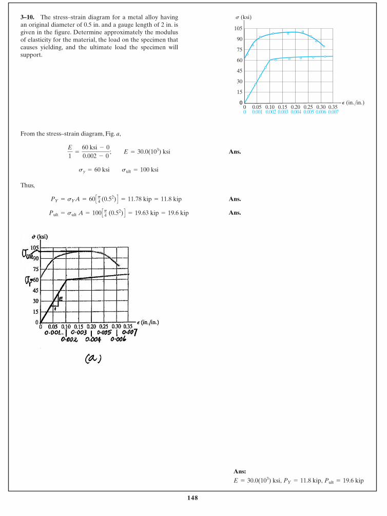
148
© 2014 Pearson Education, Inc., Upper Saddle River, NJ. All rights reserved. This material is protected under all copyright laws as they currentlyexist. No portion of this material may be reproduced, in any form or by any means, without permission in writing from the publisher.
Ans:Pult = 19.6 kipPY = 11.8 kip,E = 30.0(103) ksi,
From the stress–strain diagram, Fig. a,
Ans.
Thus,
Ans.
Ans. Pult = sult A = 100 Cp4 (0.52) D = 19.63 kip = 19.6 kip
PY = sYA = 60 Cp4 (0.52) D = 11.78 kip = 11.8 kip
sy = 60 ksi sult = 100 ksi
E
1=
60 ksi - 00.002 - 0
; E = 30.0(103) ksi
3–10. The stress–strain diagram for a metal alloy havingan original diameter of 0.5 in. and a gauge length of 2 in. isgiven in the figure. Determine approximately the modulusof elasticity for the material, the load on the specimen thatcauses yielding, and the ultimate load the specimen willsupport.
0
105
90
75
60
45
30
15
000 0.350.05 0.10 0.15 0.20 0.25 0.30
0.0070.001 0.002 0.003 0.004 0.005 0.006
P (in./in.)
s (ksi)
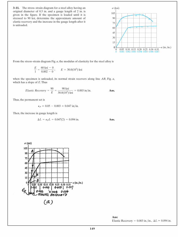
149
© 2014 Pearson Education, Inc., Upper Saddle River, NJ. All rights reserved. This material is protected under all copyright laws as they currentlyexist. No portion of this material may be reproduced, in any form or by any means, without permission in writing from the publisher.
Ans:¢L = 0.094 in.Elastic Recovery = 0.003 in.>in.,
From the stress–strain diagram Fig. a, the modulus of elasticity for the steel alloy is
when the specimen is unloaded, its normal strain recovers along line AB, Fig. a,which has a slope of E. Thus
Ans.
Thus, the permanent set is
.
Then, the increase in gauge length is
Ans.¢L = PPL = 0.047(2) = 0.094 in.
PP = 0.05 - 0.003 = 0.047 in>in
Elastic Recovery =
90E
=
90 ksi30.0(103) ksi
= 0.003 in>in.
E
1=
60 ksi - 00.002 - 0
; E = 30.0(103) ksi
3–11. The stress–strain diagram for a steel alloy having anoriginal diameter of 0.5 in. and a gauge length of 2 in. isgiven in the figure. If the specimen is loaded until it isstressed to 90 ksi, determine the approximate amount ofelastic recovery and the increase in the gauge length after itis unloaded.
0
105
90
75
60
45
30
15
000 0.350.05 0.10 0.15 0.20 0.25 0.30
0.0070.001 0.002 0.003 0.004 0.005 0.006
P (in./in.)
s (ksi)
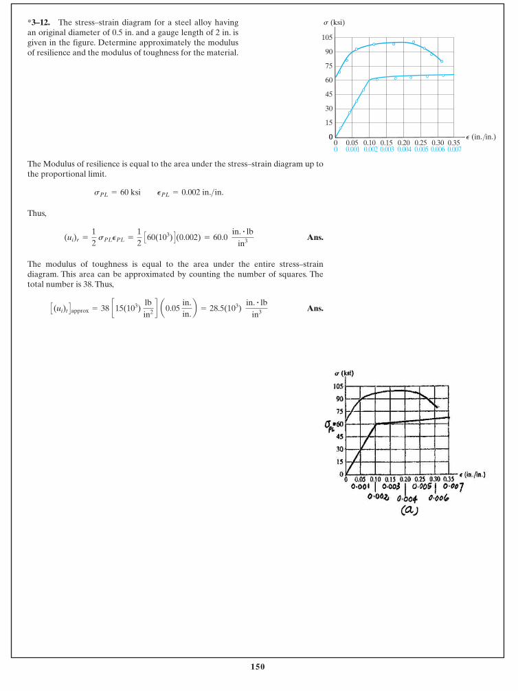
150
© 2014 Pearson Education, Inc., Upper Saddle River, NJ. All rights reserved. This material is protected under all copyright laws as they currentlyexist. No portion of this material may be reproduced, in any form or by any means, without permission in writing from the publisher.
The Modulus of resilience is equal to the area under the stress–strain diagram up tothe proportional limit.
Thus,
Ans.
The modulus of toughness is equal to the area under the entire stress–straindiagram. This area can be approximated by counting the number of squares. Thetotal number is 38. Thus,
Ans.C(ui)t Dapprox = 38 c15(103) lbin2 d a0.05
in.in.b = 28.5(103)
in. # lbin3
(ui)r =
12
sPLPPL =
12
C60(103) D(0.002) = 60.0 in. # lb
in3
sPL = 60 ksi PPL = 0.002 in.>in.
*3–12. The stress–strain diagram for a steel alloy havingan original diameter of 0.5 in. and a gauge length of 2 in. isgiven in the figure. Determine approximately the modulusof resilience and the modulus of toughness for the material.
0
105
90
75
60
45
30
15
000 0.350.05 0.10 0.15 0.20 0.25 0.30
0.0070.001 0.002 0.003 0.004 0.005 0.006
P (in./in.)
s (ksi)
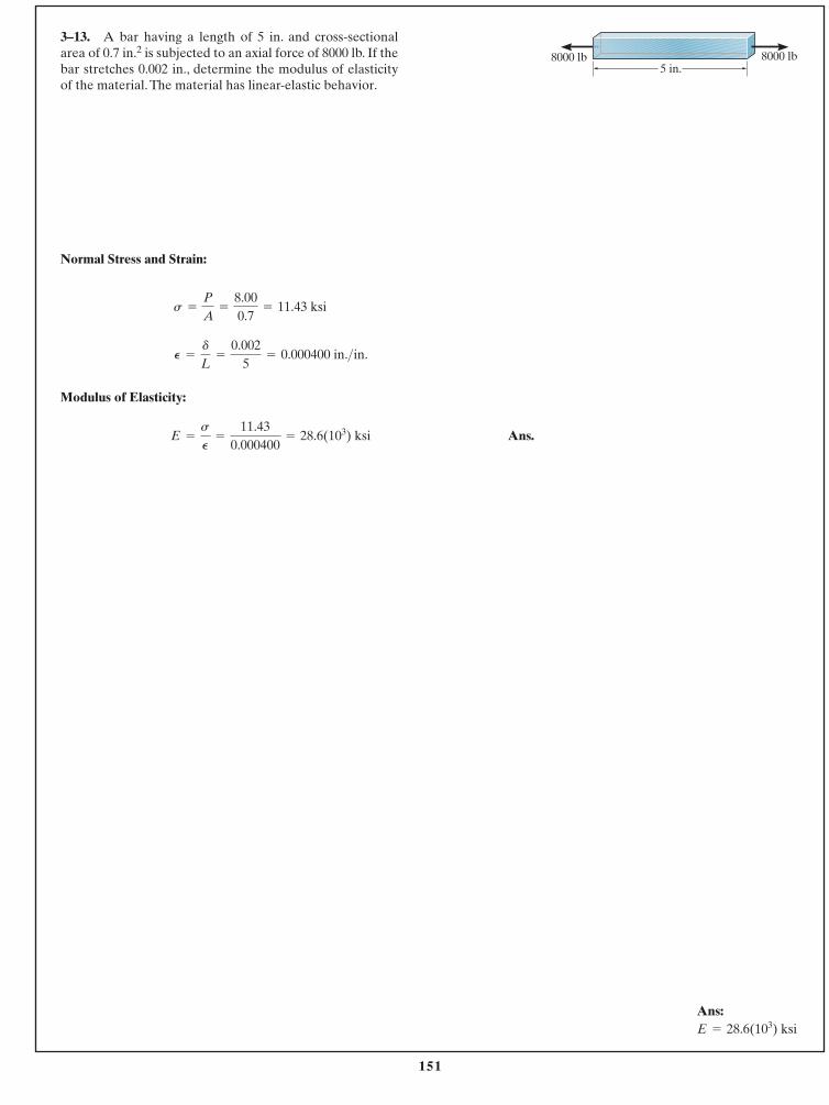
151
© 2014 Pearson Education, Inc., Upper Saddle River, NJ. All rights reserved. This material is protected under all copyright laws as they currentlyexist. No portion of this material may be reproduced, in any form or by any means, without permission in writing from the publisher.
Ans:E = 28.6(103) ksi
Normal Stress and Strain:
Modulus of Elasticity:
Ans.E =
s
P
=
11.430.000400
= 28.6(103) ksi
P =
d
L=
0.0025
= 0.000400 in.>in.
s =
P
A=
8.000.7
= 11.43 ksi
3–13. A bar having a length of 5 in. and cross-sectionalarea of 0.7 in.2 is subjected to an axial force of 8000 lb. If thebar stretches 0.002 in., determine the modulus of elasticityof the material. The material has linear-elastic behavior.
8000 lb8000 lb5 in.
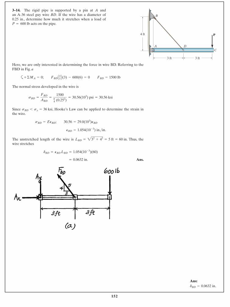
152
© 2014 Pearson Education, Inc., Upper Saddle River, NJ. All rights reserved. This material is protected under all copyright laws as they currentlyexist. No portion of this material may be reproduced, in any form or by any means, without permission in writing from the publisher.
Ans: dBD = 0.0632 in.
Here, we are only interested in determining the force in wire BD. Referring to theFBD in Fig. a
a
The normal stress developed in the wire is
Since , Hooke’s Law can be applied to determine the strain inthe wire.
The unstretched length of the wire is . Thus, thewire stretches
Ans. = 0.0632 in.
dBD = PBD LBD = 1.054(10- 3)(60)
LBD = 232+ 42
= 5 ft = 60 in
PBD = 1.054(10- 3) in.>in.
sBD = EPBD; 30.56 = 29.0(103)PBD
sBD 6 sy = 36 ksi
sBD =
FBD
ABD=
1500p4 (0.252)
= 30.56(103) psi = 30.56 ksi
+ ©MA = 0; FBD A45 B(3) - 600(6) = 0 FBD = 1500 lb
3–14. The rigid pipe is supported by a pin at A and an A-36 steel guy wire BD. If the wire has a diameter of 0.25 in., determine how much it stretches when a load ofP 600 lb acts on the pipe.=
3 ft 3 ft
CDA
B
P4 ft

153
© 2014 Pearson Education, Inc., Upper Saddle River, NJ. All rights reserved. This material is protected under all copyright laws as they currentlyexist. No portion of this material may be reproduced, in any form or by any means, without permission in writing from the publisher.
3–15. The rigid pipe is supported by a pin at A and an A-36 guy wire BD. If the wire has a diameter of 0.25 in.,determine the load P if the end C is displaced 0.15 in.downward.
Ans:P = 570 lb
Here, we are only interested in determining the force in wire BD. Referring to theFBD in Fig. a
a
The unstretched length for wire BD is . From thegeometry shown in Fig. b, the stretched length of wire BD is
Thus, the normal strain is
Then, the normal stress can be obtain by applying Hooke’s Law.
Since , the result is valid.
Ans. P = 569.57 lb = 570 lb
sBD =
FBD
ABD ; 29.01(103) =
2.50 Pp4 (0.252)
sBD 6 sy = 36 ksi
sBD = EPBD = 29(103) C1.0003(10- 3) D = 29.01 ksi
PBD =
LBD¿- LBD
LBD=
60.060017 - 6060
= 1.0003(10- 3) in.>in.
LBD¿= 2602
+ 0.0752- 2(60)(0.075) cos 143.13° = 60.060017
LBD = 232+ 42
= 5 ft = 60 in
+ ©MA = 0; FBD A45 B(3) - P(6) = 0 FBD = 2.50 P
3 ft 3 ft
CDA
B
P4 ft
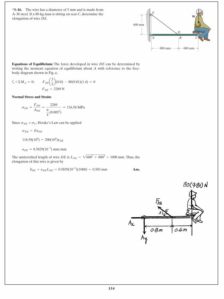
154
© 2014 Pearson Education, Inc., Upper Saddle River, NJ. All rights reserved. This material is protected under all copyright laws as they currentlyexist. No portion of this material may be reproduced, in any form or by any means, without permission in writing from the publisher.
Equations of Equilibrium: The force developed in wire DE can be determined bywriting the moment equation of equilibrium about A with reference to the free-body diagram shown in Fig. a,
a
Normal Stress and Strain:
Since , Hooke’s Law can be applied
The unstretched length of wire DE is Thus, theelongation of this wire is given by
Ans.dDE = PDELDE = 0.5829(10-3)(1000) = 0.583 mm
LDE = 26002+ 8002
= 1000 mm.
PDE = 0.5829(10-3) mm>mm
116.58(106) = 200(109)PDE
sDE = EPDE
sDE < sY
sDE =
FDE
ADE=
2289p
4 (0.0052)
= 116.58 MPa
FDE = 2289 N
FDEa35b(0.8) - 80(9.81)(1.4) = 0+ ©MA = 0;
*3–16. The wire has a diameter of 5 mm and is made fromA-36 steel. If a 80-kg man is sitting on seat C, determine theelongation of wire DE.
CB
D
A
EW
800 mm
600 mm
600 mm
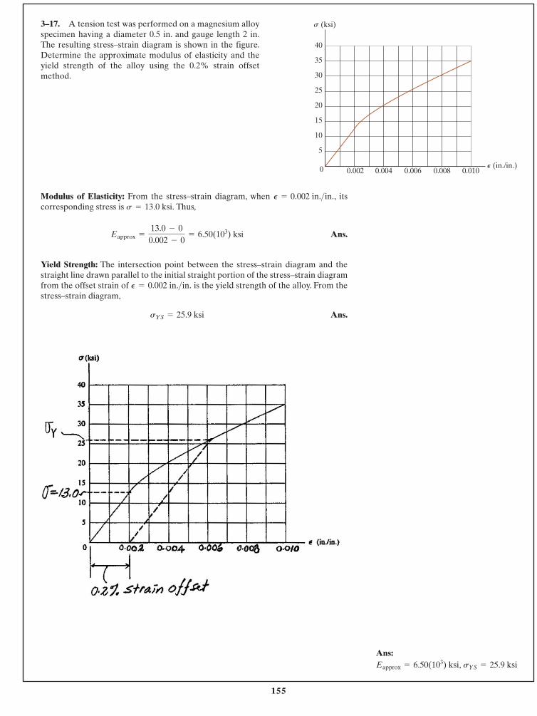
155
© 2014 Pearson Education, Inc., Upper Saddle River, NJ. All rights reserved. This material is protected under all copyright laws as they currentlyexist. No portion of this material may be reproduced, in any form or by any means, without permission in writing from the publisher.
Ans:Eapprox = 6.50(103) ksi, sYS = 25.9 ksi
3–17. A tension test was performed on a magnesium alloyspecimen having a diameter 0.5 in. and gauge length 2 in.The resulting stress–strain diagram is shown in the figure.Determine the approximate modulus of elasticity and theyield strength of the alloy using the 0.2% strain offsetmethod.
Modulus of Elasticity: From the stress–strain diagram, when , itscorresponding stress is Thus,
Ans.
Yield Strength: The intersection point between the stress–strain diagram and thestraight line drawn parallel to the initial straight portion of the stress–strain diagramfrom the offset strain of is the yield strength of the alloy. From thestress–strain diagram,
Ans.sYS = 25.9 ksi
P = 0.002 in.>in.
Eapprox =
13.0 - 00.002 - 0
= 6.50(103) ksi
s = 13.0 ksi.P = 0.002 in.>in.
s (ksi)
P (in./in.)0.002 0.004 0.006 0.008 0.010
5
10
15
20
25
30
35
40
0
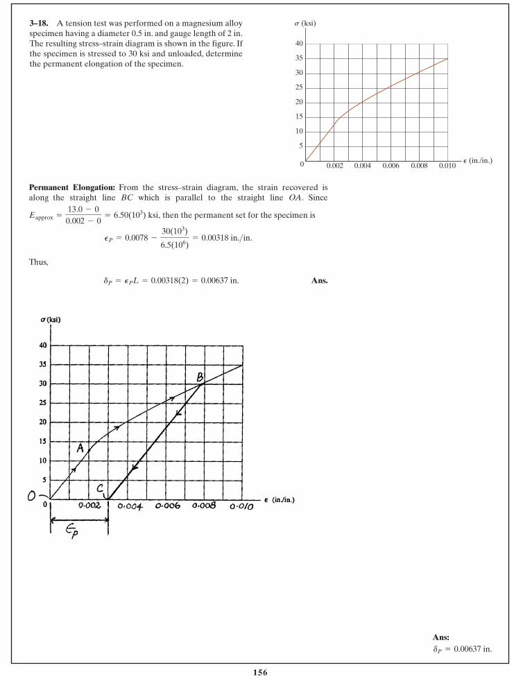
156
© 2014 Pearson Education, Inc., Upper Saddle River, NJ. All rights reserved. This material is protected under all copyright laws as they currentlyexist. No portion of this material may be reproduced, in any form or by any means, without permission in writing from the publisher.
Ans:dP = 0.00637 in.
3–18. A tension test was performed on a magnesium alloyspecimen having a diameter 0.5 in. and gauge length of 2 in.The resulting stress–strain diagram is shown in the figure. Ifthe specimen is stressed to 30 ksi and unloaded, determinethe permanent elongation of the specimen.
Permanent Elongation: From the stress–strain diagram, the strain recovered isalong the straight line BC which is parallel to the straight line OA. Since
then the permanent set for the specimen is
Thus,
Ans.dP = PPL = 0.00318(2) = 0.00637 in.
PP = 0.0078 -
30(103)
6.5(106)= 0.00318 in.>in.
Eapprox =
13.0 - 00.002 - 0
= 6.50(103) ksi,
s (ksi)
P (in./in.)0.002 0.004 0.006 0.008 0.010
5
10
15
20
25
30
35
40
0
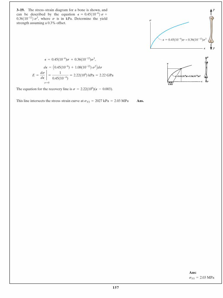
157
© 2014 Pearson Education, Inc., Upper Saddle River, NJ. All rights reserved. This material is protected under all copyright laws as they currentlyexist. No portion of this material may be reproduced, in any form or by any means, without permission in writing from the publisher.
3–19. The stress–strain diagram for a bone is shown, andcan be described by the equation �
where is in kPa. Determine the yieldstrength assuming a 0.3% offset.
s0.36110-122 s3,P = 0.45110-62 s
Ans:sYS = 2.03 MPa
P
P
P � 0.45(10�6)s + 0.36(10�12)s3
P
s
,
The equation for the recovery line is
This line intersects the stress–strain curve at Ans.sYS = 2027 kPa = 2.03 MPa
s = 2.22(106)(P - 0.003).
E =
ds
dP
2s= 0
=
1
0.45(10- 6)= 2.22(106) kPa = 2.22 GPa
dP = A0.45(10-6) + 1.08(10-12) s2 BdsP = 0.45(10-6)s + 0.36(10-12)s3
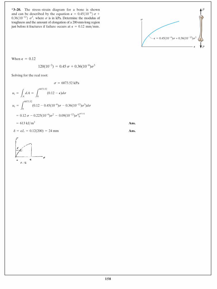
158
© 2014 Pearson Education, Inc., Upper Saddle River, NJ. All rights reserved. This material is protected under all copyright laws as they currentlyexist. No portion of this material may be reproduced, in any form or by any means, without permission in writing from the publisher.
When
Solving for the real root:
Ans.
Ans. d = PL = 0.12(200) = 24 mm
= 613 kJ>m3
= 0.12 s - 0.225(10-6)s2- 0.09(10-12)s4|
6873.52
0
ut =
L
6873.52
0(0.12 - 0.45(10-6)s - 0.36(10-12)s3)ds
ut =
LA dA =
L
6873.52
0(0.12 - P)ds
s = 6873.52 kPa
120(10-3) = 0.45 s + 0.36(10-6)s3
P = 0.12
*3–20. The stress–strain diagram for a bone is shown and can be described by the equation �
where is in kPa. Determine the modulus oftoughness and the amount of elongation of a 200-mm-long regionjust before it fractures if failure occurs at P = 0.12 mm>mm.
ss3,0.36110-1220.45110-62 sP =
P
P
P � 0.45(10�6)s + 0.36(10�12)s3
P
s
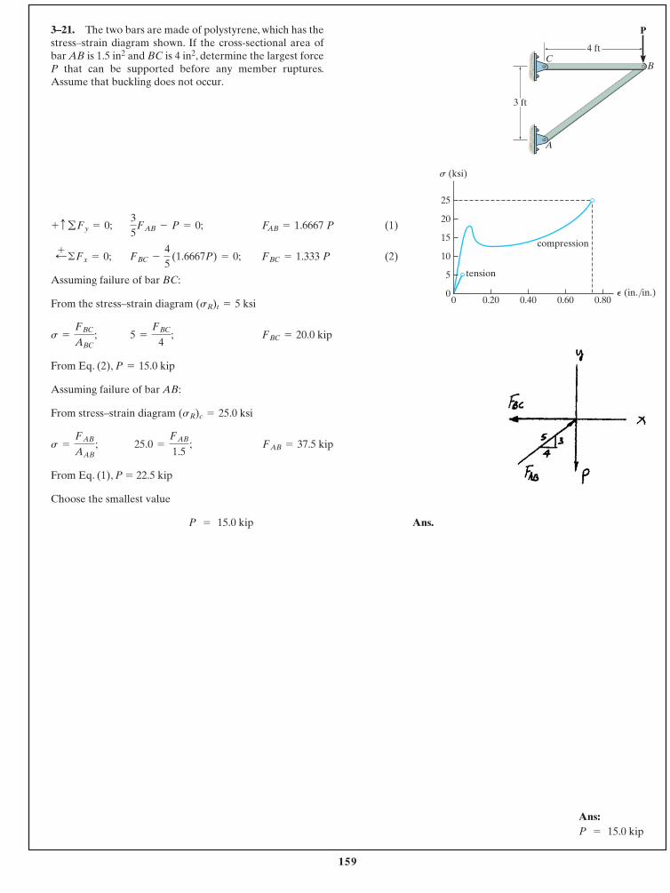
159
© 2014 Pearson Education, Inc., Upper Saddle River, NJ. All rights reserved. This material is protected under all copyright laws as they currentlyexist. No portion of this material may be reproduced, in any form or by any means, without permission in writing from the publisher.
Ans:P = 15.0 kip
3–21. The two bars are made of polystyrene, which has thestress–strain diagram shown. If the cross-sectional area ofbar AB is 1.5 in2 and BC is 4 in2, determine the largest forceP that can be supported before any member ruptures.Assume that buckling does not occur.
(1)
(2)
Assuming failure of bar BC:
From the stress–strain diagram
From Eq. (2),
Assuming failure of bar AB:
From stress–strain diagram
From Eq. (1), P � 22.5 kip
Choose the smallest value
Ans.P = 15.0 kip
FAB = 37.5 kip25.0 =
FAB
1.5 ;s =
FAB
AAB
;
(sR)c = 25.0 ksi
P = 15.0 kip
FBC = 20.0 kip5 =
FBC
4;s =
FBC
ABC;
(sR)t = 5 ksi
FBC = 1.333 PFBC -
45
(1.6667P) = 0;;+ ©Fx = 0;
FAB = 1.6667 P35
FAB - P = 0;+ cgFy = 0;
P
CB
A
3 ft
4 ft
P (in./in.)
s (ksi)
5
0
10
15
20
25
0.800.600.400.200
tension
compression
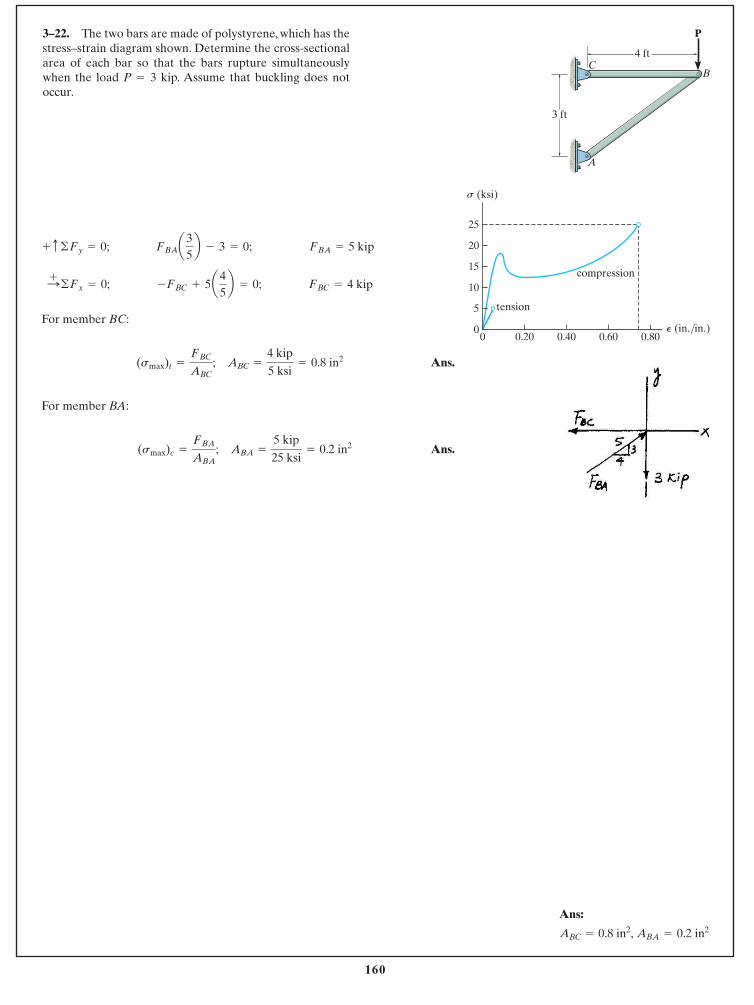
160
© 2014 Pearson Education, Inc., Upper Saddle River, NJ. All rights reserved. This material is protected under all copyright laws as they currentlyexist. No portion of this material may be reproduced, in any form or by any means, without permission in writing from the publisher.
Ans:
ABC = 0.8 in2, ABA = 0.2 in2
3–22. The two bars are made of polystyrene, which has thestress–strain diagram shown. Determine the cross-sectionalarea of each bar so that the bars rupture simultaneouslywhen the load P 3 kip. Assume that buckling does notoccur.
=
For member BC:
Ans.
For member BA:
Ans.(smax)c =
FBA
ABA; ABA =
5 kip
25 ksi= 0.2 in2
(smax)t =
FBC
ABC; ABC =
4 kip
5 ksi= 0.8 in2
FBC = 4 kip-FBC + 5a45b = 0;:+ ©Fx = 0;
FBA = 5 kipFBAa35b - 3 = 0;+ c ©Fy = 0;
P
CB
A
3 ft
4 ft
P (in./in.)
s (ksi)
5
0
10
15
20
25
0.800.600.400.200
tension
compression
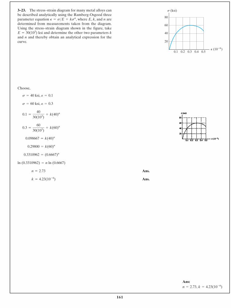
161
© 2014 Pearson Education, Inc., Upper Saddle River, NJ. All rights reserved. This material is protected under all copyright laws as they currentlyexist. No portion of this material may be reproduced, in any form or by any means, without permission in writing from the publisher.
Ans:n = 2.73, k = 4.23(10- 6)
3–23. The stress–strain diagram for many metal alloys canbe described analytically using the Ramberg-Osgood threeparameter equation , where E, k, and n aredetermined from measurements taken from the diagram.Using the stress–strain diagram shown in the figure, take
ksi and determine the other two parameters kand n and thereby obtain an analytical expression for thecurve.
E = 30(103)
P = s>E + ksn
Choose,
Ans.
Ans.k = 4.23(10- 6)
n = 2.73
ln (0.3310962) = n ln (0.6667)
0.3310962 = (0.6667)n
0.29800 = k(60)n
0.098667 = k(40)n
0.3 =
6030(103)
+ k(60)n
0.1 =
4030(103)
+ k(40)n
s = 60 ksi, e = 0.3
s = 40 ksi, e = 0.1
s (ksi)
P (10– 6)0.1 0.2 0.3 0.4 0.5
80
60
40
20
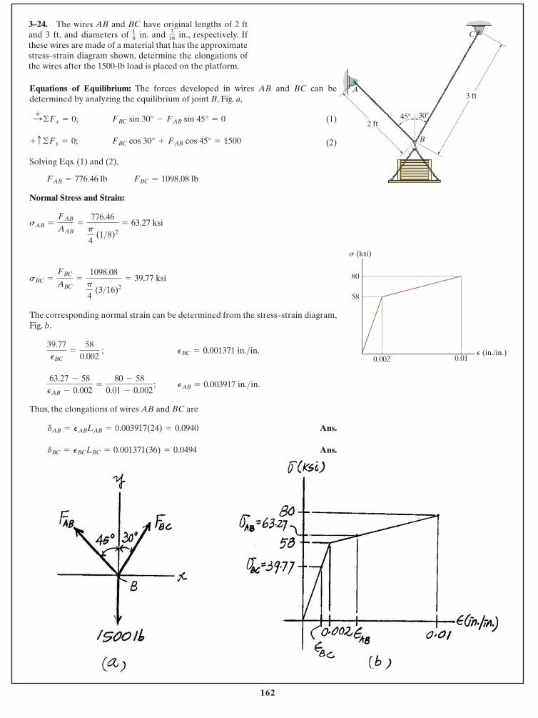
162
© 2014 Pearson Education, Inc., Upper Saddle River, NJ. All rights reserved. This material is protected under all copyright laws as they currentlyexist. No portion of this material may be reproduced, in any form or by any means, without permission in writing from the publisher.
3–24. The wires AB and BC have original lengths of 2 ftand 3 ft, and diameters of in. and in., respectively. Ifthese wires are made of a material that has the approximatestress–strain diagram shown, determine the elongations ofthe wires after the 1500-lb load is placed on the platform.
316
18
Equations of Equilibrium: The forces developed in wires AB and BC can bedetermined by analyzing the equilibrium of joint B, Fig. a,
(1)
(2)
Solving Eqs. (1) and (2),
Normal Stress and Strain:
The corresponding normal strain can be determined from the stress–strain diagram,Fig. b.
Thus, the elongations of wires AB and BC are
Ans.
Ans.dBC = PBCLBC = 0.001371(36) = 0.0494
dAB = PABLAB = 0.003917(24) = 0.0940
PAB = 0.003917 in.>in.63.27 - 58
PAB - 0.002=
80 - 580.01 - 0.002
;
PBC = 0.001371 in.>in.39.77PBC
=
580.002
;
sBC =
FBC
ABC=
1098.08p
4 (3>16)2
= 39.77 ksi
sAB =
FAB
AAB=
776.46p
4 (1>8)2
= 63.27 ksi
FBC = 1098.08 lbFAB = 776.46 lb
FBC cos 30° + FAB cos 45° = 1500+ c ©Fy = 0;
FBC sin 30° - FAB sin 45° = 0:+ ©Fx = 0;
58
0.002 0.01
80
s (ksi)
P (in./in.)
2 ft45� 30�
3 ftA
C
B
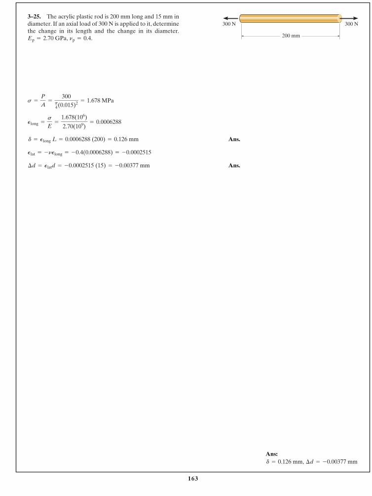
163
© 2014 Pearson Education, Inc., Upper Saddle River, NJ. All rights reserved. This material is protected under all copyright laws as they currentlyexist. No portion of this material may be reproduced, in any form or by any means, without permission in writing from the publisher.
Ans.
Ans.¢d = Platd = -0.0002515 (15) = -0.00377 mm
Plat = -nPlong = -0.4(0.0006288) = -0.0002515
d = Plong L = 0.0006288 (200) = 0.126 mm
Plong =
s
E=
1.678(106)
2.70(109)= 0.0006288
s =
P
A=
300p4(0.015)2 = 1.678 MPa
3–25. The acrylic plastic rod is 200 mm long and 15 mm indiameter. If an axial load of 300 N is applied to it, determinethe change in its length and the change in its diameter.
np = 0.4.Ep = 2.70 GPa,
Ans:d = 0.126 mm, ¢d = -0.00377 mm
300 N
200 mm
300 N
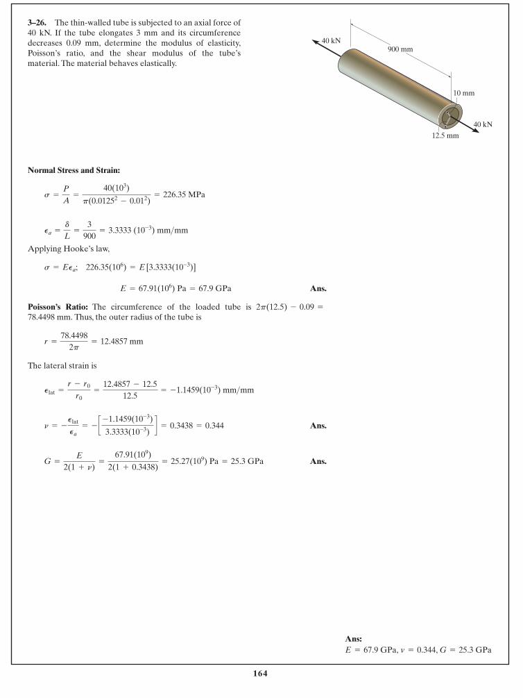
164
© 2014 Pearson Education, Inc., Upper Saddle River, NJ. All rights reserved. This material is protected under all copyright laws as they currentlyexist. No portion of this material may be reproduced, in any form or by any means, without permission in writing from the publisher.
Ans:E = 67.9 GPa, v = 0.344, G = 25.3 GPa
3–26. The thin-walled tube is subjected to an axial force of40 kN. If the tube elongates 3 mm and its circumferencedecreases 0.09 mm, determine the modulus of elasticity,Poisson’s ratio, and the shear modulus of the tube’smaterial. The material behaves elastically.
Normal Stress and Strain:
Applying Hooke’s law,
Ans.
Poisson’s Ratio: The circumference of the loaded tube is Thus, the outer radius of the tube is
The lateral strain is
Ans.
Ans.G =
E
2(1 + n)=
67.91(109)
2(1 + 0.3438)= 25.27(109) Pa = 25.3 GPa
n = -
Plat
Pa= - c -1.1459(10-3)
3.3333(10-3)d = 0.3438 = 0.344
Plat =
r - r0
r0=
12.4857 - 12.512.5
= -1.1459(10-3) mm>mm
r =
78.44982p
= 12.4857 mm
78.4498 mm.2p(12.5) - 0.09 =
E = 67.91(106) Pa = 67.9 GPa
s = EPa; 226.35(106) = E [3.3333(10-3)]
Pa =
d
L=
3900
= 3.3333 (10-3) mm>mm
s =
P
A=
40(103)
p(0.01252- 0.012)
= 226.35 MPa
40 kN
40 kN
10 mm
12.5 mm
900 mm
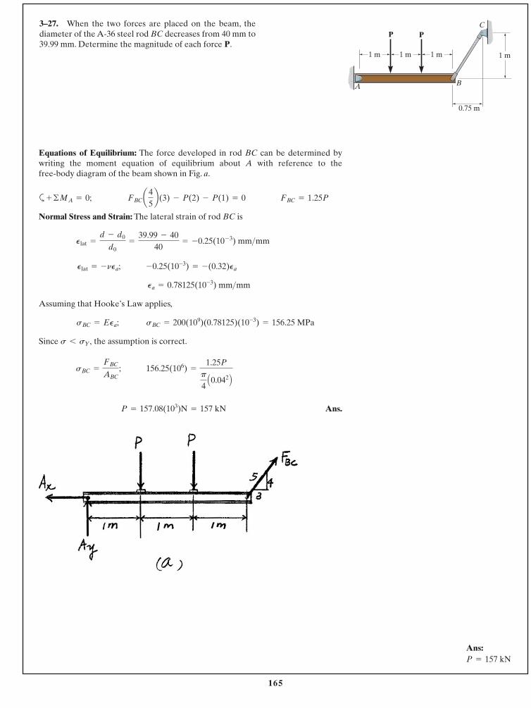
165
© 2014 Pearson Education, Inc., Upper Saddle River, NJ. All rights reserved. This material is protected under all copyright laws as they currentlyexist. No portion of this material may be reproduced, in any form or by any means, without permission in writing from the publisher.
3–27. When the two forces are placed on the beam, thediameter of the A-36 steel rod BC decreases from 40 mm to39.99 mm. Determine the magnitude of each force P.
Ans:P = 157 kN
Equations of Equilibrium: The force developed in rod BC can be determined bywriting the moment equation of equilibrium about A with reference to the free-body diagram of the beam shown in Fig. a.
a
Normal Stress and Strain: The lateral strain of rod BC is
Assuming that Hooke’s Law applies,
Since the assumption is correct.
Ans.P = 157.08(103)N = 157 kN
156.25(106) =
1.25Pp
4A0.042 BsBC =
FBC
ABC;
s 6 sY,
sBC = EPa; sBC = 200(109)(0.78125)(10-3) = 156.25 MPa
Pa = 0.78125(10-3) mm>mm
Plat = -nPa; -0.25(10-3) = -(0.32)Pa
Plat =
d - d0
d0=
39.99 - 4040
= -0.25(10- 3) mm>mm
FBC = 1.25PFBCa45b(3) - P(2) - P(1) = 0+ ©MA = 0;
1 m 1 m 1 m
0.75 m
1 m
A B
P PC
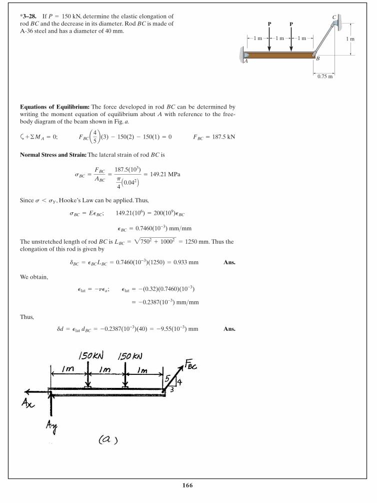
166
© 2014 Pearson Education, Inc., Upper Saddle River, NJ. All rights reserved. This material is protected under all copyright laws as they currentlyexist. No portion of this material may be reproduced, in any form or by any means, without permission in writing from the publisher.
*3–28. If P 150 kN, determine the elastic elongation ofrod BC and the decrease in its diameter. Rod BC is made of A-36 steel and has a diameter of 40 mm.
=
Equations of Equilibrium: The force developed in rod BC can be determined bywriting the moment equation of equilibrium about A with reference to the free-body diagram of the beam shown in Fig. a.
a
Normal Stress and Strain: The lateral strain of rod BC is
Since , Hooke’s Law can be applied. Thus,
The unstretched length of rod BC is Thus theelongation of this rod is given by
Ans.
We obtain,
;
Thus,
Ans.dd = Plat dBC = -0.2387(10-3)(40) = -9.55(10-3) mm
= -0.2387(10-3) mm>mm
Plat = -(0.32)(0.7460)(10-3)Plat = -nPa
dBC = PBCLBC = 0.7460(10-3)(1250) = 0.933 mm
LBC = 27502+ 10002
= 1250 mm.
PBC = 0.7460(10-3) mm>mm
sBC = EPBC; 149.21(106) = 200(109)PBC
s 6 sY
sBC =
FBC
ABC=
187.5(103)
p
4A0.042 B = 149.21 MPa
FBC = 187.5 kNFBCa45b(3) - 150(2) - 150(1) = 0+ ©MA = 0;
1 m 1 m 1 m
0.75 m
1 m
A B
P PC
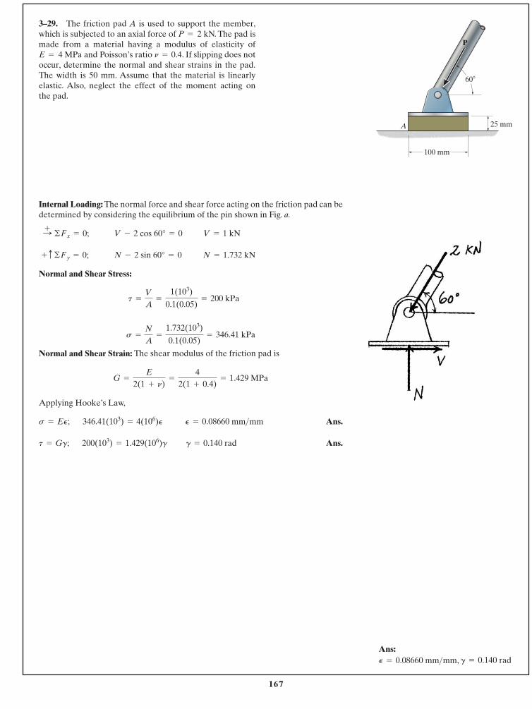
167
© 2014 Pearson Education, Inc., Upper Saddle River, NJ. All rights reserved. This material is protected under all copyright laws as they currentlyexist. No portion of this material may be reproduced, in any form or by any means, without permission in writing from the publisher.
Ans:
3–29. The friction pad A is used to support the member,which is subjected to an axial force of P 2 kN. The pad ismade from a material having a modulus of elasticity of E 4 MPa and Poisson’s ratio . If slipping does notoccur, determine the normal and shear strains in the pad.The width is 50 mm. Assume that the material is linearlyelastic. Also, neglect the effect of the moment acting on the pad.
n = 0.4=
=
Internal Loading: The normal force and shear force acting on the friction pad can bedetermined by considering the equilibrium of the pin shown in Fig. a.
Normal and Shear Stress:
Normal and Shear Strain: The shear modulus of the friction pad is
Applying Hooke’s Law,
Ans.
Ans.g = 0.140 rad200(103) = 1.429(106)gt = Gg;
P = 0.08660 mm>mm346.41(103) = 4(106)Ps = EP;
G =
E
2(1 + n)=
42(1 + 0.4)
= 1.429 MPa
s =
N
A=
1.732(103)
0.1(0.05)= 346.41 kPa
t =
V
A=
1(103)
0.1(0.05)= 200 kPa
N = 1.732 kNN - 2 sin 60° = 0 + c ©Fy = 0;
V = 1 kNV - 2 cos 60° = 0 :+ ©Fx = 0;
100 mm
25 mm
60�
A
P
P = 0.08660 mm>mm, g = 0.140 rad
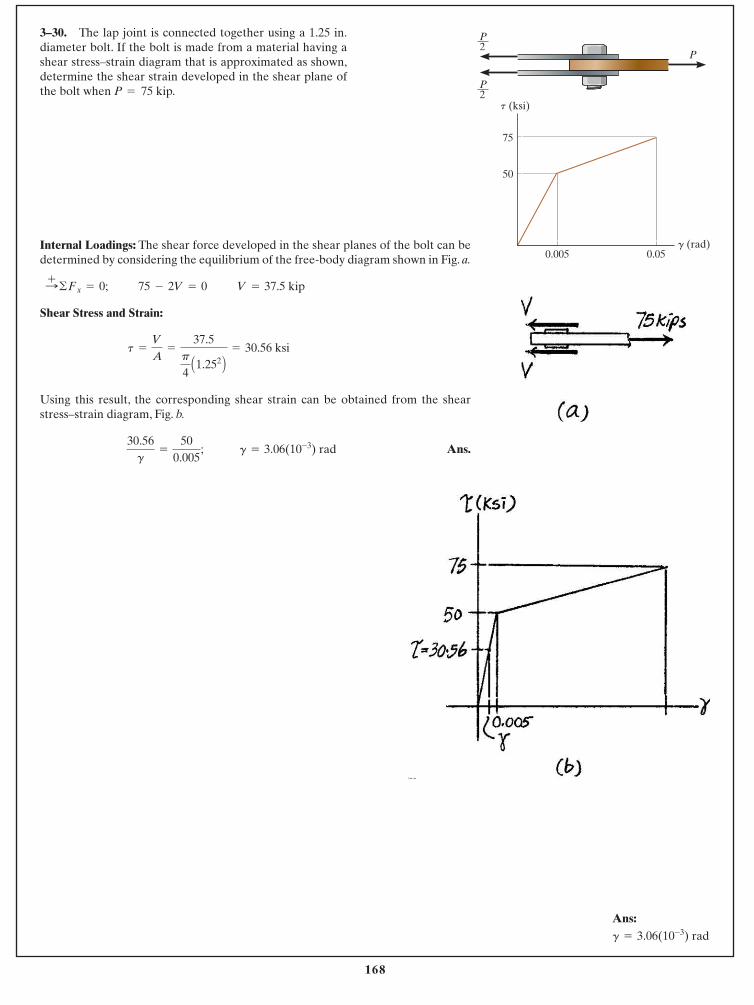
168
© 2014 Pearson Education, Inc., Upper Saddle River, NJ. All rights reserved. This material is protected under all copyright laws as they currentlyexist. No portion of this material may be reproduced, in any form or by any means, without permission in writing from the publisher.
Ans:g = 3.06(10-3) rad
3–30. The lap joint is connected together using a 1.25 in.diameter bolt. If the bolt is made from a material having ashear stress–strain diagram that is approximated as shown,determine the shear strain developed in the shear plane ofthe bolt when P 75 kip.=
Internal Loadings: The shear force developed in the shear planes of the bolt can bedetermined by considering the equilibrium of the free-body diagram shown in Fig. a.
Shear Stress and Strain:
Using this result, the corresponding shear strain can be obtained from the shearstress–strain diagram, Fig. b.
Ans.30.56g
=
500.005
; g = 3.06(10-3) rad
t =
V
A=
37.5p
4A1.252 B = 30.56 ksi
V = 37.5 kip75 - 2V = 0:+ ©Fx = 0;
50
0.005 0.05
75
t (ksi)
g (rad)
P2
P
P2
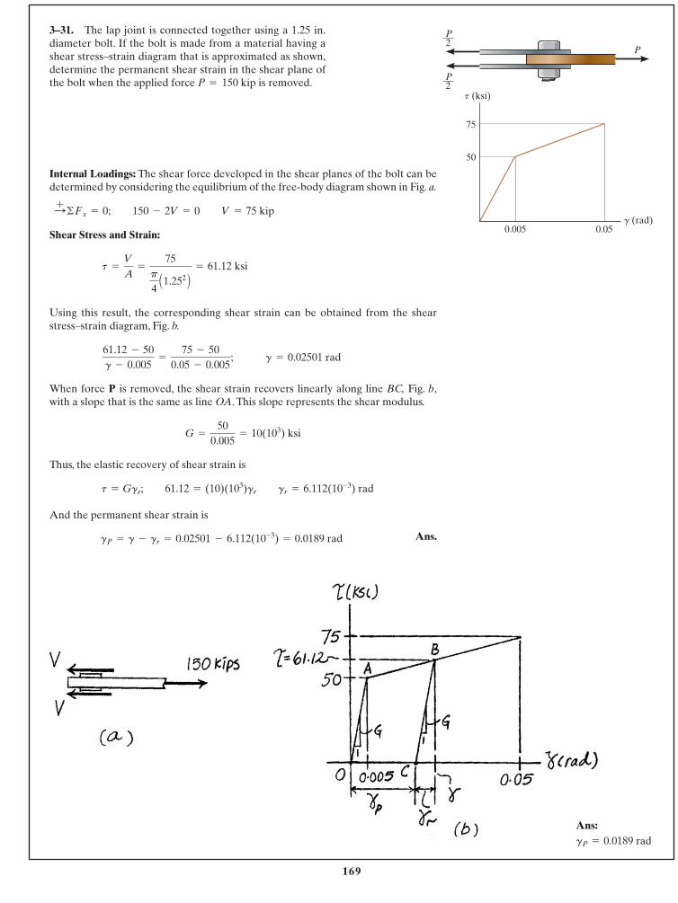
169
© 2014 Pearson Education, Inc., Upper Saddle River, NJ. All rights reserved. This material is protected under all copyright laws as they currentlyexist. No portion of this material may be reproduced, in any form or by any means, without permission in writing from the publisher.
3–31. The lap joint is connected together using a 1.25 in.diameter bolt. If the bolt is made from a material having ashear stress–strain diagram that is approximated as shown,determine the permanent shear strain in the shear plane ofthe bolt when the applied force P 150 kip is removed.=
Internal Loadings: The shear force developed in the shear planes of the bolt can bedetermined by considering the equilibrium of the free-body diagram shown in Fig. a.
Shear Stress and Strain:
Using this result, the corresponding shear strain can be obtained from the shearstress–strain diagram, Fig. b.
When force P is removed, the shear strain recovers linearly along line BC, Fig. b,with a slope that is the same as line OA. This slope represents the shear modulus.
Thus, the elastic recovery of shear strain is
And the permanent shear strain is
Ans.gP = g - gr = 0.02501 - 6.112(10-3) = 0.0189 rad
t = Ggr; 61.12 = (10)(103)gr gr = 6.112(10-3) rad
G =
500.005
= 10(103) ksi
61.12 - 50g - 0.005
=
75 - 500.05 - 0.005
; g = 0.02501 rad
t =
V
A=
75p
4A1.252 B = 61.12 ksi
V = 75 kip150 - 2V = 0:+ ©Fx = 0;
50
0.005 0.05
75
t (ksi)
g (rad)
P2
P
P2
Ans:gP = 0.0189 rad
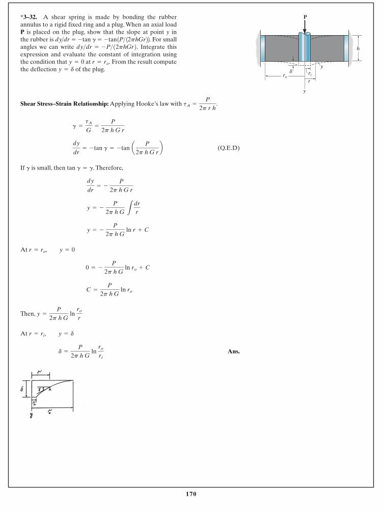
170
© 2014 Pearson Education, Inc., Upper Saddle River, NJ. All rights reserved. This material is protected under all copyright laws as they currentlyexist. No portion of this material may be reproduced, in any form or by any means, without permission in writing from the publisher.
Shear Stress–Strain Relationship: Applying Hooke’s law with .
(Q.E.D)
If is small, then tan . Therefore,
At
Then,
At
Ans.d =
P
2p h G ln
ro
ri
r = ri, y = d
y =
P
2p h G ln
ro
r
C =
P
2p h G ln ro
0 = - P
2p h G ln ro + C
r = ro, y = 0
y = - P
2p h G ln r + C
y = - P
2p h G L
drr
dy
dr= -
P
2p h G r
g = gg
dy
dr= - tan g = - tan a P
2p h G rb
g =
tA
G=
P
2p h G r
tA =
P
2p r h
*3–32. A shear spring is made by bonding the rubberannulus to a rigid fixed ring and a plug. When an axial loadP is placed on the plug, show that the slope at point y inthe rubber is For smallangles we can write Integrate thisexpression and evaluate the constant of integration usingthe condition that at From the result computethe deflection of the plug.y = d
r = ro.y = 0
dy>dr = -P>12phGr2.- tan1P>12phGr22.dy>dr = - tan g =
P
y
rori
y
r
h
d
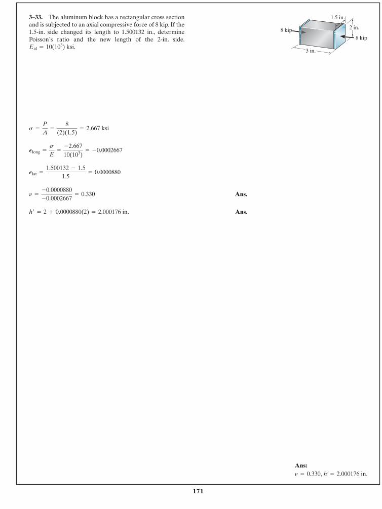
171
© 2014 Pearson Education, Inc., Upper Saddle River, NJ. All rights reserved. This material is protected under all copyright laws as they currentlyexist. No portion of this material may be reproduced, in any form or by any means, without permission in writing from the publisher.
3–33. The aluminum block has a rectangular cross sectionand is subjected to an axial compressive force of 8 kip. If the1.5-in. side changed its length to 1.500132 in., determinePoisson’s ratio and the new length of the 2-in. side.
ksi.Eal = 10(103)
Ans.
Ans.h¿ = 2 + 0.0000880(2) = 2.000176 in.
n =
-0.0000880-0.0002667
= 0.330
Plat =
1.500132 - 1.51.5
= 0.0000880
Plong =
s
E=
-2.66710(103)
= -0.0002667
s =
P
A=
8(2)(1.5)
= 2.667 ksi
Ans:n = 0.330, h¿ = 2.000176 in.
3 in.
1.5 in.
8 kip8 kip 2 in.
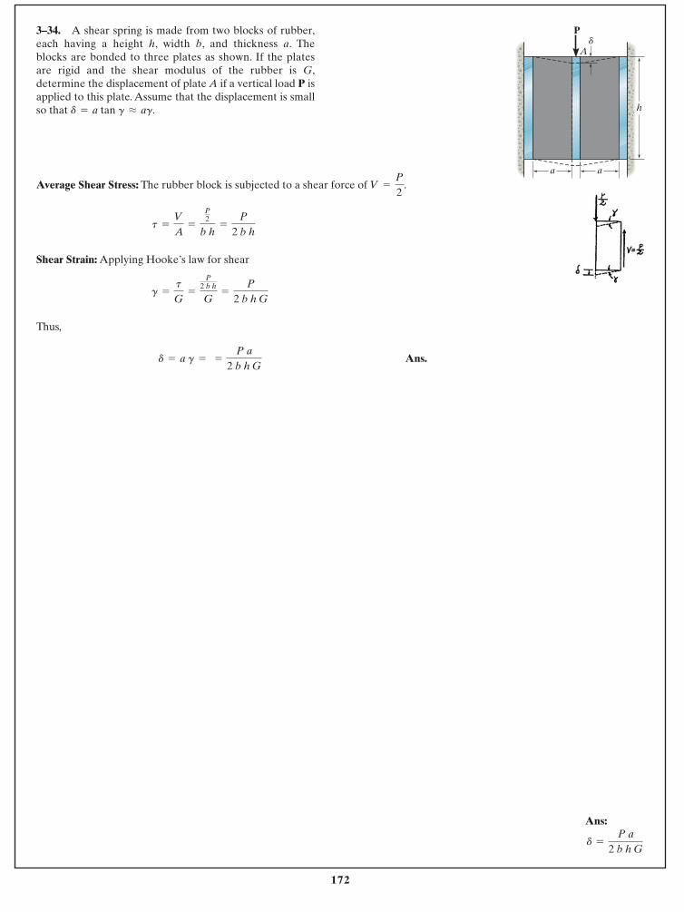
172
© 2014 Pearson Education, Inc., Upper Saddle River, NJ. All rights reserved. This material is protected under all copyright laws as they currentlyexist. No portion of this material may be reproduced, in any form or by any means, without permission in writing from the publisher.
Average Shear Stress: The rubber block is subjected to a shear force of .
Shear Strain: Applying Hooke’s law for shear
Thus,
Ans.d = a g = =
P a2 b h G
g =
t
G=
P2 b h
G=
P
2 b h G
t =
V
A=
P2
b h=
P
2 b h
V =
P
2
3–34. A shear spring is made from two blocks of rubber,each having a height h, width b, and thickness a. Theblocks are bonded to three plates as shown. If the platesare rigid and the shear modulus of the rubber is G,determine the displacement of plate A if a vertical load P isapplied to this plate. Assume that the displacement is smallso that d = a tan g L ag.
Ans:
d =
P a2 b h G
P
h
aa
Ad
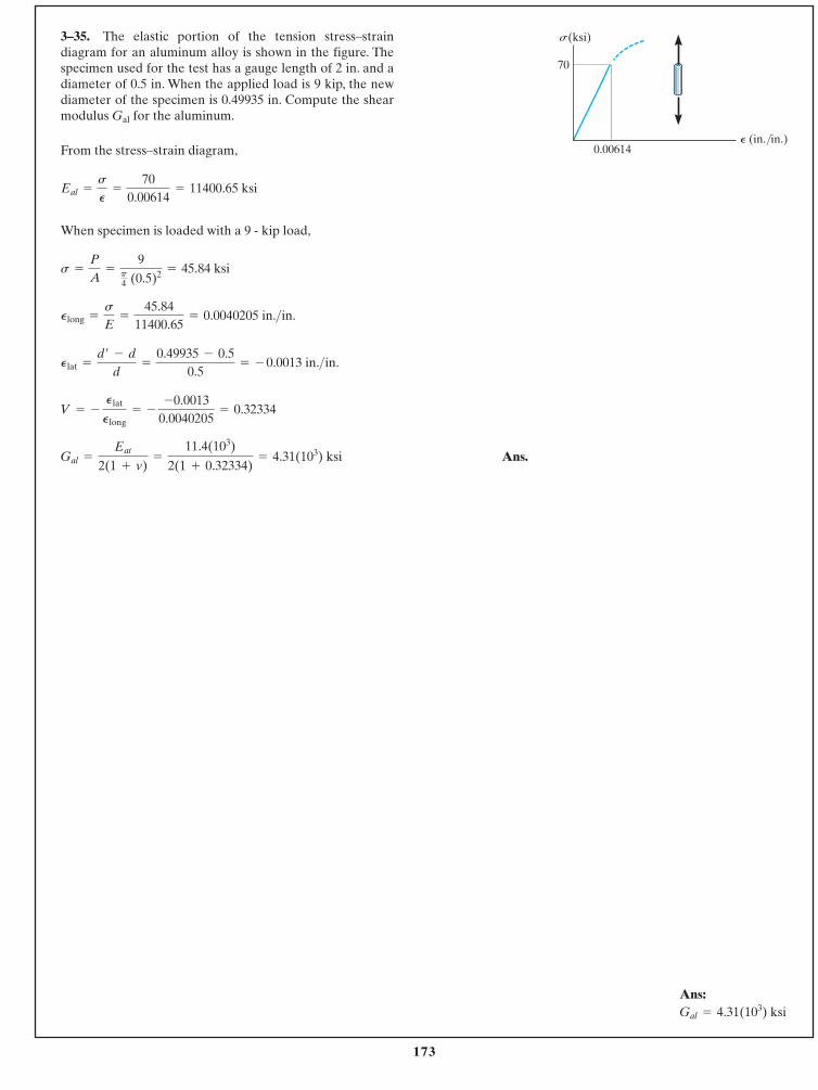
173
© 2014 Pearson Education, Inc., Upper Saddle River, NJ. All rights reserved. This material is protected under all copyright laws as they currentlyexist. No portion of this material may be reproduced, in any form or by any means, without permission in writing from the publisher.
From the stress–strain diagram,
When specimen is loaded with a 9 - kip load,
Ans.Gal =
Eat
2(1 + v)=
11.4(103)
2(1 + 0.32334)= 4.31(103) ksi
V = -
Plat
Plong= -
-0.00130.0040205
= 0.32334
Plat =
d¿ - d
d=
0.49935 - 0.50.5
= - 0.0013 in.>in.
Plong =
s
E=
45.8411400.65
= 0.0040205 in.>in.
s =
P
A=
9p4 (0.5)2 = 45.84 ksi
Eal =
s
P
=
700.00614
= 11400.65 ksi
3–35. The elastic portion of the tension stress–straindiagram for an aluminum alloy is shown in the figure. Thespecimen used for the test has a gauge length of 2 in. and adiameter of 0.5 in. When the applied load is 9 kip, the newdiameter of the specimen is 0.49935 in. Compute the shearmodulus for the aluminum.Gal
Ans:Gal = 4.31(103) ksi
0.00614
70
s(ksi)
P (in./in.)
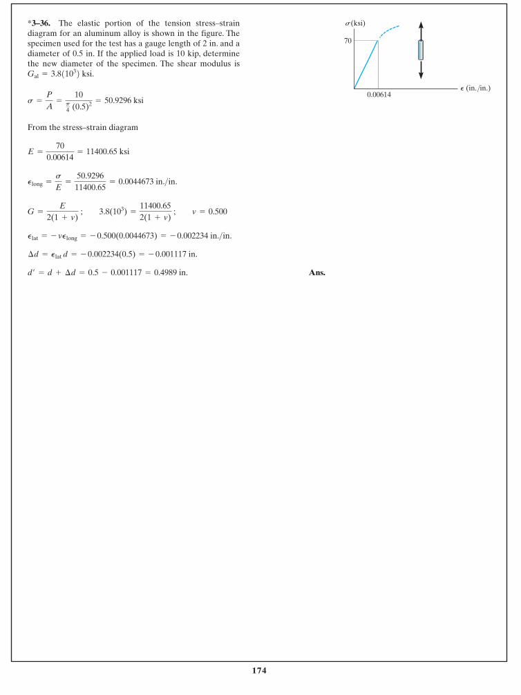
174
© 2014 Pearson Education, Inc., Upper Saddle River, NJ. All rights reserved. This material is protected under all copyright laws as they currentlyexist. No portion of this material may be reproduced, in any form or by any means, without permission in writing from the publisher.
From the stress–strain diagram
Ans.d¿ = d + ¢d = 0.5 - 0.001117 = 0.4989 in.
¢d = Plat d = - 0.002234(0.5) = - 0.001117 in.
Plat = - vPlong = - 0.500(0.0044673) = - 0.002234 in.>in.
G =
E
2(1 + v) ; 3.8(103) =
11400.652(1 + v)
; v = 0.500
Plong =
s
E=
50.929611400.65
= 0.0044673 in.>in.
E =
700.00614
= 11400.65 ksi
s =
P
A=
10p4 (0.5)2 = 50.9296 ksi
*3–36. The elastic portion of the tension stress–straindiagram for an aluminum alloy is shown in the figure. Thespecimen used for the test has a gauge length of 2 in. and adiameter of 0.5 in. If the applied load is 10 kip, determinethe new diameter of the specimen. The shear modulus isGal = 3.811032 ksi.
0.00614
70
s(ksi)
P (in./in.)
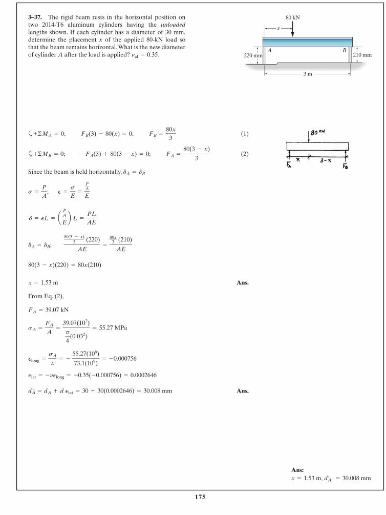
175
© 2014 Pearson Education, Inc., Upper Saddle River, NJ. All rights reserved. This material is protected under all copyright laws as they currentlyexist. No portion of this material may be reproduced, in any form or by any means, without permission in writing from the publisher.
3–37. The rigid beam rests in the horizontal position ontwo 2014-T6 aluminum cylinders having the unloadedlengths shown. If each cylinder has a diameter of 30 mm.determine the placement x of the applied 80-kN load sothat the beam remains horizontal.What is the new diameterof cylinder A after the load is applied? .nal = 0.35
a (1)
a (2)
Since the beam is held horizontally,
Ans.
From Eq. (2),
Ans.dA¿ = dA + d Plat = 30 + 30(0.0002646) = 30.008 mm
Plat = -nPlong = -0.35(-0.000756) = 0.0002646
Plong =
sA
E= -
55.27(106)
73.1(109)= -0.000756
sA =
FA
A=
39.07(103)
p
4(0.032)
= 55.27 MPa
FA = 39.07 kN
x = 1.53 m
80(3 - x)(220) = 80x(210)
dA = dB; 80(3 - x)
3 (220)
AE=
80x3 (210)
AE
d = PL = aPA
Eb L =
PL
AE
P =
s
E=
PA
Es =
P
A;
dA = dB
FA =
80(3 - x)
3-FA(3) + 80(3 - x) = 0;+ ©MB = 0;
FB =
80x
3FB(3) - 80(x) = 0;+ ©MA = 0;
Ans:x = 1.53 m, dA¿ = 30.008 mm
3 m
210 mm220 mm
x
A B
80 kN
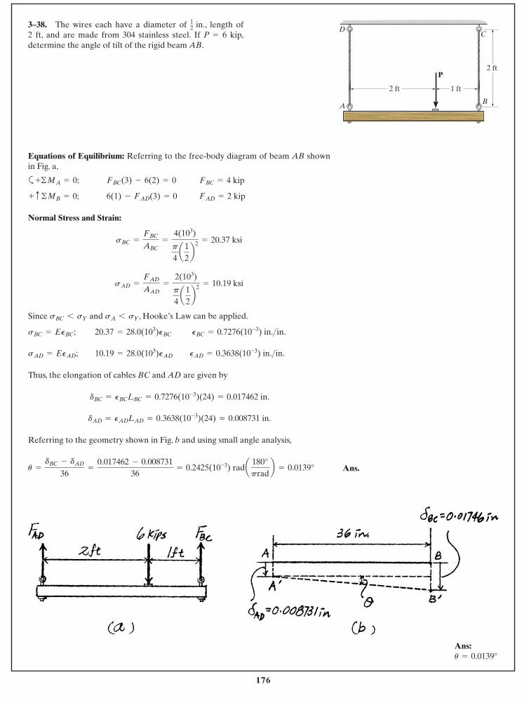
176
© 2014 Pearson Education, Inc., Upper Saddle River, NJ. All rights reserved. This material is protected under all copyright laws as they currentlyexist. No portion of this material may be reproduced, in any form or by any means, without permission in writing from the publisher.
3–38. The wires each have a diameter of in., length of 2 ft, and are made from 304 stainless steel. If P 6 kip,determine the angle of tilt of the rigid beam AB.
=
12
Equations of Equilibrium: Referring to the free-body diagram of beam AB shownin Fig. a,
a
Normal Stress and Strain:
Since and , Hooke’s Law can be applied.
Thus, the elongation of cables BC and AD are given by
Referring to the geometry shown in Fig. b and using small angle analysis,
u =
dBC - dAD
36=
0.017462 - 0.00873136
= 0.2425(10-3) rada 180°prad
b = 0.0139°
dAD = PADLAD = 0.3638(10-3)(24) = 0.008731 in.
dBC = PBCLBC = 0.7276(10-3)(24) = 0.017462 in.
PAD = 0.3638(10-3) in.>in.10.19 = 28.0(103)PADsAD = EPAD;
PBC = 0.7276(10-3) in.>in.20.37 = 28.0(103)PBCsBC = EPBC;
sA 6 sYsBC 6 sY
sAD =
FAD
AAD=
2(103)
p
4a1
2b2 = 10.19 ksi
sBC =
FBC
ABC=
4(103)
p
4a1
2b2 = 20.37 ksi
FAD = 2 kip6(1) - FAD(3) = 0+ c ©MB = 0;
FBC = 4 kipFBC(3) - 6(2) = 0+ ©MA = 0;
C
B
D
A
2 ft
2 ft
1 ft
P
Ans.
Ans:u = 0.0139°
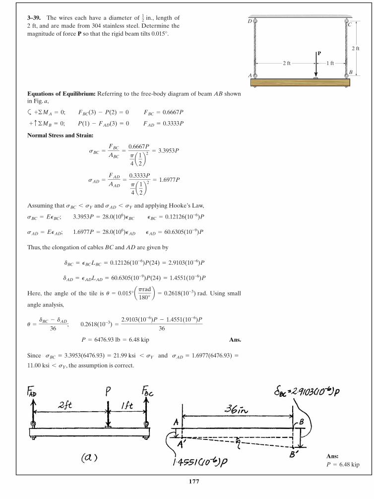
177
© 2014 Pearson Education, Inc., Upper Saddle River, NJ. All rights reserved. This material is protected under all copyright laws as they currentlyexist. No portion of this material may be reproduced, in any form or by any means, without permission in writing from the publisher.
3–39. The wires each have a diameter of in., length of 2 ft, and are made from 304 stainless steel. Determine themagnitude of force P so that the rigid beam tilts 0.015°.
12
Equations of Equilibrium: Referring to the free-body diagram of beam AB shownin Fig. a,
a
Normal Stress and Strain:
Assuming that and and applying Hooke’s Law,
Thus, the elongation of cables BC and AD are given by
Here, the angle of the tile is Using small
angle analysis,
Ans.
Since and
, the assumption is correct.11.00 ksi 6 sY
sAD = 1.6977(6476.93) =sBC = 3.3953(6476.93) = 21.99 ksi 6 sY
P = 6476.93 lb = 6.48 kip
0.2618(10-3) =
2.9103(10-6)P - 1.4551(10-6)P
36u =
dBC - dAD
36;
u = 0.015°aprad180°
b = 0.2618(10-3) rad.
dAD = PADLAD = 60.6305(10-9)P(24) = 1.4551(10-6)P
dBC = PBCLBC = 0.12126(10-6)P(24) = 2.9103(10-6)P
PAD = 60.6305(10-9)P1.6977P = 28.0(106)PADsAD = EPAD;
PBC = 0.12126(10-6)P3.3953P = 28.0(106)PBCsBC = EPBC;
sAD 6 sYsBC 6 sY
sAD =
FAD
AAD=
0.3333P
p
4a1
2b2 = 1.6977P
sBC =
FBC
ABC=
0.6667P
p
4a1
2b2 = 3.3953P
FAD = 0.3333PP(1) - FAD(3) = 0 + c ©MB = 0;
FBC = 0.6667PFBC(3) - P(2) = 0+ ©MA = 0;
C
B
D
A
2 ft
2 ft
1 ft
P
Ans:P = 6.48 kip
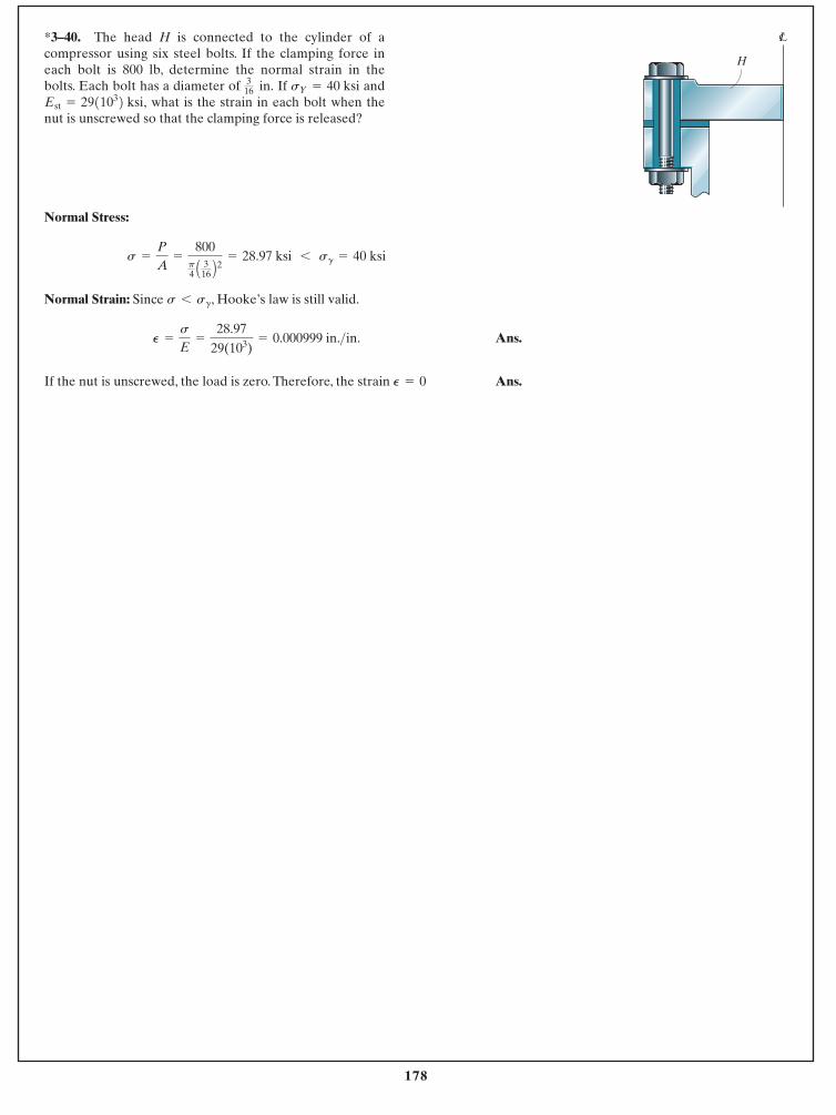
178
© 2014 Pearson Education, Inc., Upper Saddle River, NJ. All rights reserved. This material is protected under all copyright laws as they currentlyexist. No portion of this material may be reproduced, in any form or by any means, without permission in writing from the publisher.
Normal Stress:
Normal Strain: Since , Hooke’s law is still valid.
Ans.
If the nut is unscrewed, the load is zero. Therefore, the strain Ans.P = 0
P =
s
E=
28.9729(103)
= 0.000999 in.>in.
s 6 sg
s =
P
A=
800p4 A 3
16 B2 = 28.97 ksi 6 sg = 40 ksi
*3–40. The head H is connected to the cylinder of acompressor using six steel bolts. If the clamping force ineach bolt is 800 lb, determine the normal strain in thebolts. Each bolt has a diameter of If and
what is the strain in each bolt when thenut is unscrewed so that the clamping force is released?Est = 2911032 ksi,
sY = 40 ksi316 in.
H
LC
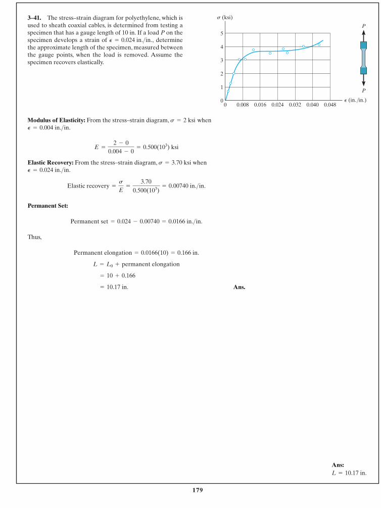
179
© 2014 Pearson Education, Inc., Upper Saddle River, NJ. All rights reserved. This material is protected under all copyright laws as they currentlyexist. No portion of this material may be reproduced, in any form or by any means, without permission in writing from the publisher.
3–41. The stress–strain diagram for polyethylene, which isused to sheath coaxial cables, is determined from testing aspecimen that has a gauge length of 10 in. If a load P on thespecimen develops a strain of determinethe approximate length of the specimen, measured betweenthe gauge points, when the load is removed. Assume thespecimen recovers elastically.
P = 0.024 in.>in.,
Modulus of Elasticity: From the stress–strain diagram, when
Elastic Recovery: From the stress–strain diagram, when
Permanent Set:
Thus,
Ans.= 10.17 in.
= 10 + 0.166
L = L0 + permanent elongation
Permanent elongation = 0.0166(10) = 0.166 in.
Permanent set = 0.024 - 0.00740 = 0.0166 in.>in.
Elastic recovery =
s
E=
3.700.500(103)
= 0.00740 in.>in.
P = 0.024 in.>in.s = 3.70 ksi
E =
2 - 00.004 - 0
= 0.500(103) ksi
P = 0.004 in.>in.s = 2 ksi
Ans:L = 10.17 in.
P
P5
4
3
2
1
00.008 0.016 0.024 0.032 0.040 0.048
s (ksi)
0P (in./in.)
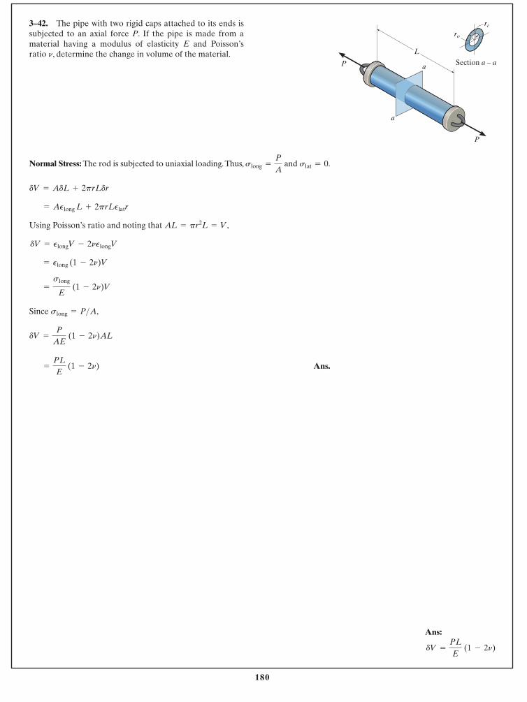
180
© 2014 Pearson Education, Inc., Upper Saddle River, NJ. All rights reserved. This material is protected under all copyright laws as they currentlyexist. No portion of this material may be reproduced, in any form or by any means, without permission in writing from the publisher.
Ans:
dV =
PL
E (1 - 2n)
3–42. The pipe with two rigid caps attached to its ends issubjected to an axial force P. If the pipe is made from amaterial having a modulus of elasticity E and Poisson’sratio n, determine the change in volume of the material.
Normal Stress: The rod is subjected to uniaxial loading.Thus, and .
Using Poisson’s ratio and noting that ,
Since
Ans.=
PL
E (1 - 2n)
dV =
P
AE (1 - 2n)AL
slong = P>A,
=
slong
E (1 - 2n)V
= Plong (1 - 2n)V
dV = PlongV - 2nPlongV
AL = pr2L = V
= APlong L + 2prLPlatr
dV = AdL + 2prLdr
slat = 0slong =
P
A
a
a
L
Section a – a
P
P
ri
ro