4 magnetic field
TRANSCRIPT

8/2/2019 4 Magnetic Field
http://slidepdf.com/reader/full/4-magnetic-field 1/102
PhysicsPhysicsap erap er
1919
1
CHAPTER 19:CHAPTER 19:Magnetic fieldMagnetic field
(7 Hours)(7 Hours)
w w w .
k m p
h . m
a t ri k
. e d
u . m
y
w w w .
k m p
h . m
a t ri k
. e d
u . m
y

8/2/2019 4 Magnetic Field
http://slidepdf.com/reader/full/4-magnetic-field 2/102
PhysicsPhysicsap erap er1919
2
Overview:
w w w .
k m p
h . m
a t ri k
. e d
u . m
y
w w w .
k m p
h . m
a t ri k
. e d
u . m
y ElectrostaticsElectrostatics
Coulomb’sCoulomb’s
lawlaw
Charge in uniformCharge in uniform
Electric fieldElectric field
Electric fieldElectric field EquipotentialEquipotential
surfacesurface
Electric fieldElectric field
strengthstrength
ElectricElectric
potentialpotential
PotentialPotential
energyenergy
I N P R O G
R E S S
I N P R O G
R E S S

8/2/2019 4 Magnetic Field
http://slidepdf.com/reader/full/4-magnetic-field 3/102
PhysicsPhysicsap erap er1919
3
At the end of this chapter, students should be able to:At the end of this chapter, students should be able to:
DefineDefine magnetic field.magnetic field.
IdentifyIdentify magnetic field sources.magnetic field sources.
SketchSketch the magnetic field lines.the magnetic field lines.
Learning Outcome:
19.1 Magnetic field (1 hour)
w w w .
k m p
h . m
a t ri k
. e d
u . m
y
w w w .
k m p
h . m
a t ri k
. e d
u . m
y

8/2/2019 4 Magnetic Field
http://slidepdf.com/reader/full/4-magnetic-field 4/102
PhysicsPhysicsap erap er1919
4
is defined as a region around a magnet where a magnetica region around a magnet where a magnetic
force can be experiencedforce can be experienced.
A stationary electric chargestationary electric charge is surrounded by an electricsurrounded by an electric
field onlyfield only.
When an electric charge moveselectric charge moves, it is surrounded by ansurrounded by anelectric field and a magnetic fieldelectric field and a magnetic field. The motion of the electricmotion of the electric
charge produces the magnetic fieldcharge produces the magnetic field.
Magnetic field has two poles, called north (N)north (N) and south (S)south (S).This magnetic poles are always found in pairsfound in pairs whereas asingle magnetic pole has never been found.
Like poles (N-N or S-S) repelLike poles (N-N or S-S) repel each other.
Opposite poles (N-S) attractOpposite poles (N-S) attract each other.
19.1 Magnetic field

8/2/2019 4 Magnetic Field
http://slidepdf.com/reader/full/4-magnetic-field 5/102
PhysicsPhysicsap erap er1919
5
Magnetic field lines are used to represent a magnetic field.
By convention, magnetic field lines leave the north poleleave the north pole andenters the south poleenters the south pole of a magnet.
Magnetic field lines can be represented by straight lines or curves. The tangent to a curved field linetangent to a curved field line at a pointindicates the direction of the magnetic fielddirection of the magnetic field at that point
as shown in Figure 19.1.
Magnetic field can be represented by crossescrosses or by dotteddotted
circlescircles as shown in Figures 19.2a and 19.2b.
19.1.1 Magnetic field lines
Figure 19.1Figure 19.1
direction of magnetic field
at point P.PP
Figure 19.2a : magnetic field linesFigure 19.2a : magnetic field lines
enter enter the page perpendicularlythe page perpendicularly
XX XX XX XX
XX XX XX XX
Figure 19.2b : magnetic field linesFigure 19.2b : magnetic field lines
leaveleave the page perpendicularlythe page perpendicularly
8/2/2019 4 Magnetic Field
http://slidepdf.com/reader/full/4-magnetic-field 6/102
PhysicsPhysicsap erap er1919
6
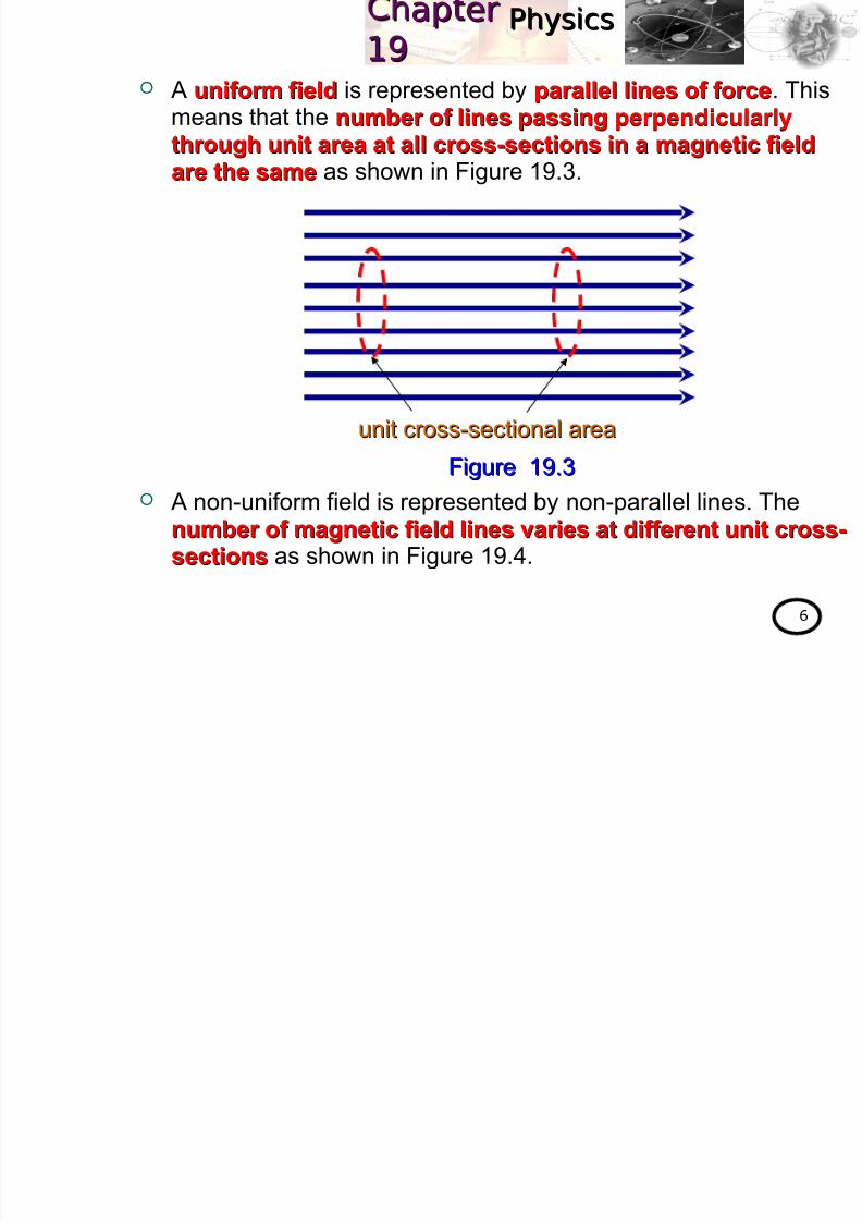
A uniform fielduniform field is represented by parallel lines of forceparallel lines of force. Thismeans that the number of lines passing perpendicularlynumber of lines passing perpendicularly
through unit area at all cross-sections in a magnetic fieldthrough unit area at all cross-sections in a magnetic fieldare the sameare the same as shown in Figure 19.3.
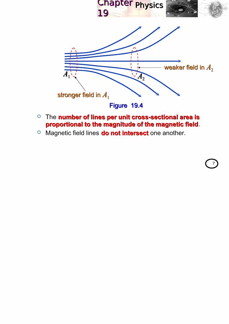
A non-uniform field is represented by non-parallel lines. The
number of magnetic field lines varies at different unit cross-number of magnetic field lines varies at different unit cross-
sectionssections as shown in Figure 19.4.
Figure 19.3Figure 19.3
unit cross-sectional areaunit cross-sectional area
8/2/2019 4 Magnetic Field
http://slidepdf.com/reader/full/4-magnetic-field 7/102
PhysicsPhysicsap erap er1919
7
The number of lines per unit cross-sectional area isnumber of lines per unit cross-sectional area isproportional to the magnitude of the magnetic fieldproportional to the magnitude of the magnetic field.
Magnetic field lines do not intersectdo not intersect one another.
Figure 19.4Figure 19.4
stronger field instronger field in A A11
A A11
A A
22
weaker field inweaker field in A A22

8/2/2019 4 Magnetic Field
http://slidepdf.com/reader/full/4-magnetic-field 8/102
PhysicsPhysicsap erap er1919
8
The pattern of the magnetic field lines can be determined by
using two methods. compass needlescompass needles (shown in Figure 19.5)
sprinkling iron filings on paper sprinkling iron filings on paper (shown in Figure 19.6).
19.1.2 Magnetic field lines pattern
Figure 19.5: plotting a magnetic field line of a bar magnetic.Figure 19.5: plotting a magnetic field line of a bar magnetic.
Figure 19.6: thin iron filing indicate the magnetic field lines.Figure 19.6: thin iron filing indicate the magnetic field lines.

8/2/2019 4 Magnetic Field
http://slidepdf.com/reader/full/4-magnetic-field 9/102
PhysicsPhysicsap erap er1919
9
Figures 19.7 shows the various pattern of magnetic field linesaround the magnets.
Figure 19.7aFigure 19.7a
a. Bar magnet
b. Horseshoe or U magnet
Figure 19.7bFigure 19.7b

8/2/2019 4 Magnetic Field
http://slidepdf.com/reader/full/4-magnetic-field 10/102
PhysicsPhysicsap erap er1919
10
d. Two bar magnets (like poleslike poles) - repulsiverepulsive
Neutral point (point wherewhere
the resultant magneticthe resultant magnetic
force is zeroforce is zero).
c. Two bar magnets (unlike poleunlike pole) - attractiveattractive
Figure 19.7cFigure 19.7c
Figure 19.7dFigure 19.7d
8/2/2019 4 Magnetic Field
http://slidepdf.com/reader/full/4-magnetic-field 11/102
PhysicsPhysicsap erap er1919
Southmagnetic pole
Southgeographical pole
Northmagnetic pole
11.5°
11
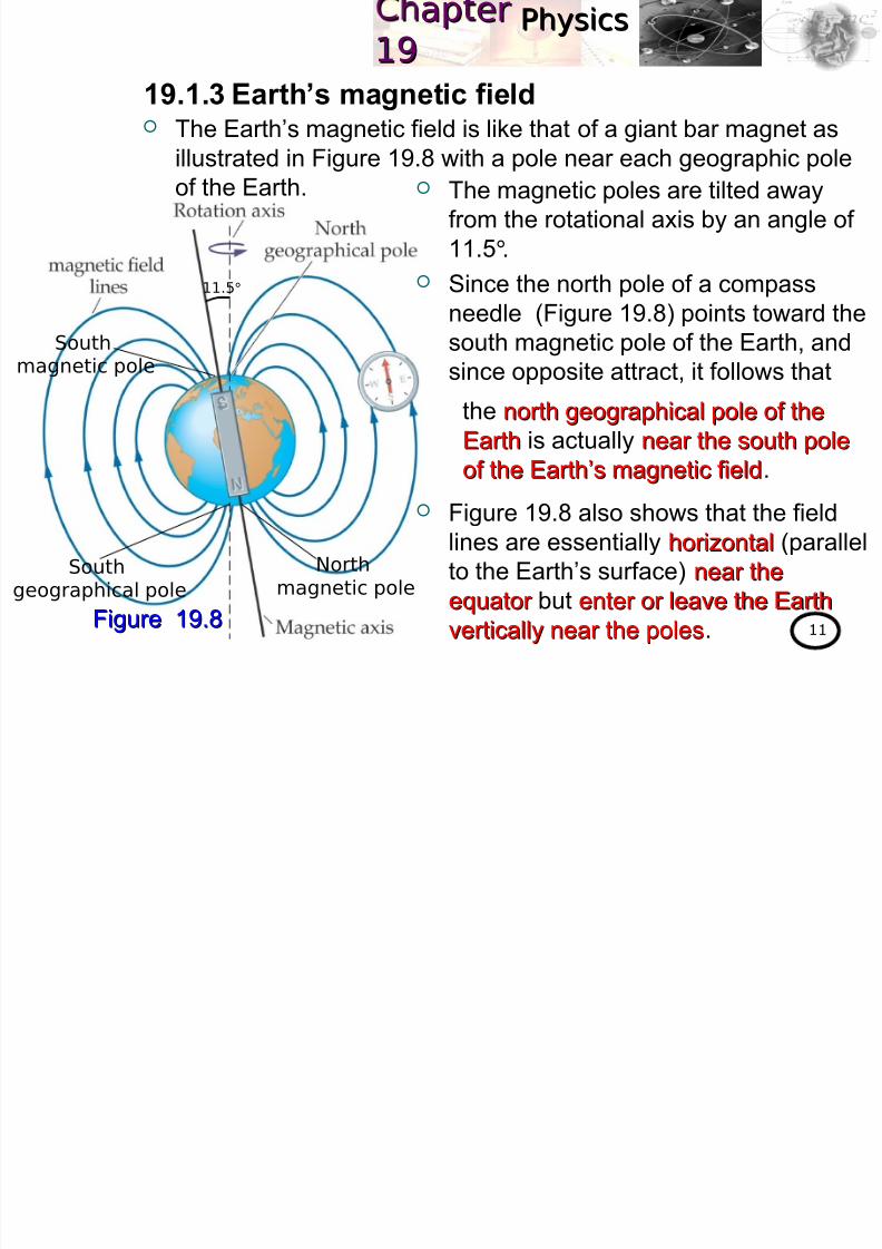
The Earth’s magnetic field is like that of a giant bar magnet as
illustrated in Figure 19.8 with a pole near each geographic poleof the Earth.
19.1.3 Earth’s magnetic field
Figure 19.8Figure 19.8
The magnetic poles are tilted away
from the rotational axis by an angle of
11.5°.
Since the north pole of a compass
needle (Figure 19.8) points toward thesouth magnetic pole of the Earth, and
since opposite attract, it follows that
Figure 19.8 also shows that the field
lines are essentially horizontalhorizontal (parallel
to the Earth’s surface) near thenear the
equator equator but enter or leave the Earthenter or leave the Earth
vertically near the polesvertically near the poles.
the north geographical pole of thenorth geographical pole of the
EarthEarth is actually near the south polenear the south pole
of the Earth’s magnetic fieldof the Earth’s magnetic field.
h i

8/2/2019 4 Magnetic Field
http://slidepdf.com/reader/full/4-magnetic-field 12/102
PhysicsPhysicsap erap er1919
12
Using the permanent magnetUsing the permanent magnet
One permanent magnet A permanent magnet is bring near to the soft iron and
touching the surface of the soft iron by following the path inthe Figure 19.9.
This method is called induced magnetizationinduced magnetization.
The arrowsarrows in the soft iron represent the magnetizationdirection with the arrowhead being the north pole and arrowtail being the south pole. It is also known as domainsdomains ( thethe
tiny magnetized region because of spin magnetictiny magnetized region because of spin magneticmoment of the electronmoment of the electron).
19.1.4 Magnetization of a Soft Iron
Figure 19.9Figure 19.9 NN SS
Ph i
8/2/2019 4 Magnetic Field
http://slidepdf.com/reader/full/4-magnetic-field 13/102
PhysicsPhysicsap erap er1919
13
In an unmagnetized piece of soft iron, these domains arearranged randomly but it is aligned in one direction when the
soft iron becomes magnetized. The soft iron becomes a temporary magnet with its south
pole facing the north pole of the permanent magnet and viceversa as shown in Figure 19.9.
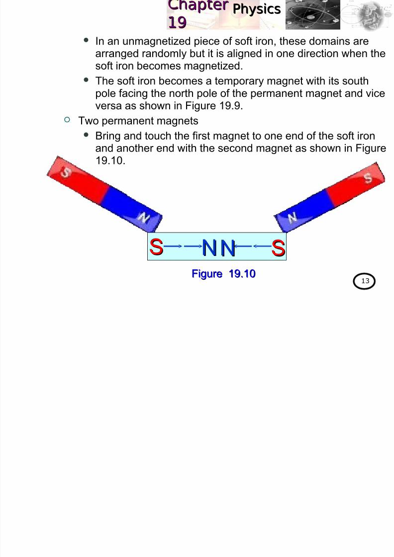
Two permanent magnets
Bring and touch the first magnet to one end of the soft ironand another end with the second magnet as shown in Figure19.10.
NN NN SSSS
Figure 19.10Figure 19.10
h iPh iap erap er

8/2/2019 4 Magnetic Field
http://slidepdf.com/reader/full/4-magnetic-field 14/102
PhysicsPhysicsap erap er1919
14
Figure 19.11Figure 19.11
NN SS
Switch, S
I I I I
SSNN
Current -Current -
anticlockwiseanticlockwiseCurrent - clockwiseCurrent - clockwise
Using the electrical circuitUsing the electrical circuit
A soft iron is placed inside a solenoid (a long coil of wire
consisting of many loops of wire) that is connected to the power supply as shown in Figure 19.11.
When the switch S is closed, the current I flows in the solenoid
and produces magnetic field.
The directions of the fields associated with the solenoid can be
found by viewing the current flows in the solenoid from bothviewing the current flows in the solenoid from both
endend or applying the right hand grip ruleright hand grip rule as shown in Figure19.11.
Ph iPh iap erap er
8/2/2019 4 Magnetic Field
http://slidepdf.com/reader/full/4-magnetic-field 15/102
PhysicsPhysicsap erap er1919
15
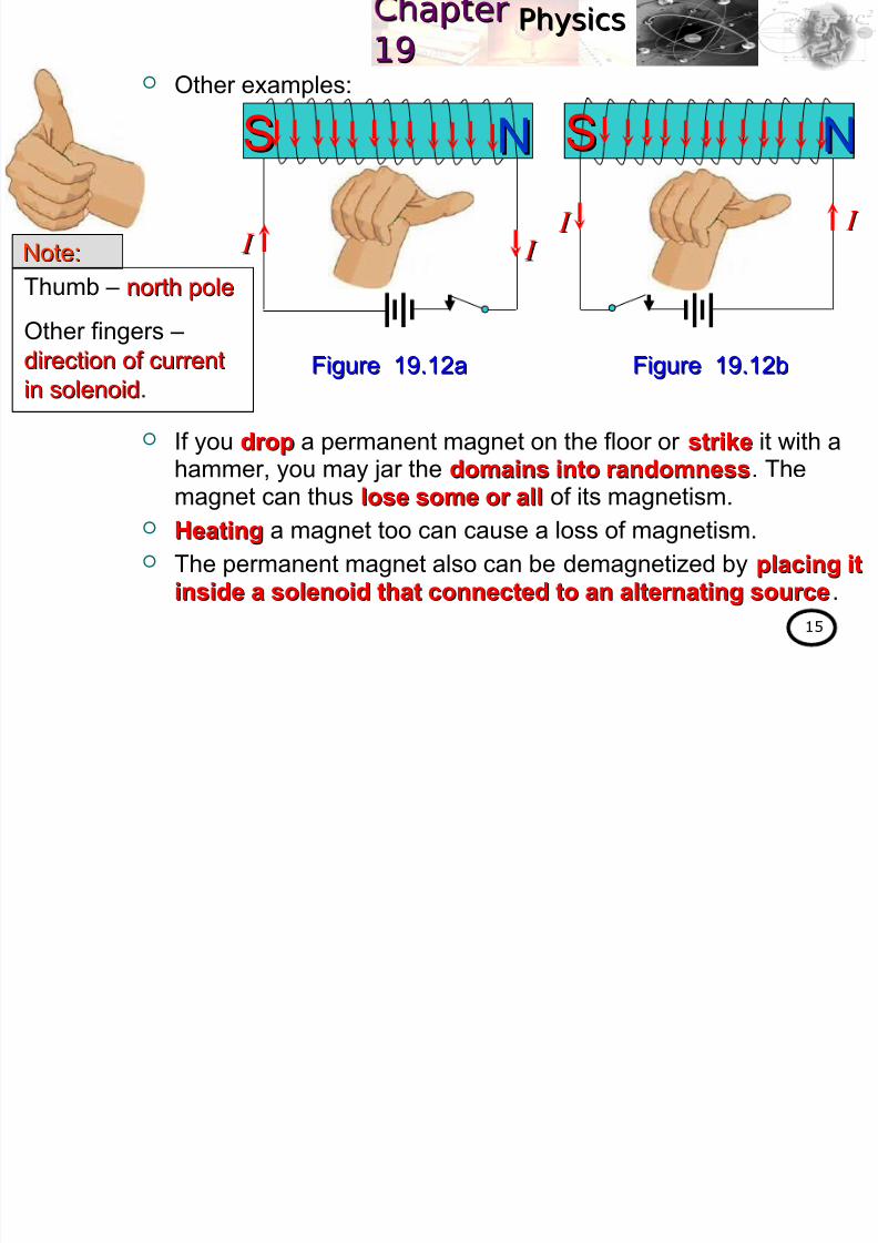
Other examples:
If you dropdrop a permanent magnet on the floor or strikestrike it with a
hammer, you may jar the domains into randomnessdomains into randomness. Themagnet can thus lose some or alllose some or all of its magnetism.
HeatingHeating a magnet too can cause a loss of magnetism.
The permanent magnet also can be demagnetized by placing itplacing it
inside a solenoid that connected to an alternating sourceinside a solenoid that connected to an alternating source.
NNSS
I I I I I I I I
SS NN
Thumb – north polenorth pole
Other fingers –
direction of currentdirection of current
in solenoidin solenoid.
Note:Note:
Figure 19.12aFigure 19.12a Figure 19.12bFigure 19.12b
Ph iPh iap erap er

8/2/2019 4 Magnetic Field
http://slidepdf.com/reader/full/4-magnetic-field 16/102
PhysicsPhysicsap erap er1919
16
is defined as the magnetic flux per unit area across anthe magnetic flux per unit area across an
area at right angles to the magnetic fieldarea at right angles to the magnetic field.
Mathematically,
It also known as magnetic inductionmagnetic induction (magnetic field intensitymagnetic field intensity
OR strengthOR strength) It is a vector quantityvector quantity and its direction follows the direction of the direction of
the magnetic fieldthe magnetic field.
Its unit is tesla (T)tesla (T) OR weber per metre squared (Wb mweber per metre squared (Wb m −22)). Unit conversion :
19.1.5 Magnetic flux density, B
⊥
= A
BΦ
wherefluxmagnetic:Φ
fieldmagneticthetoanglesrightatarea:⊥ A
)G(gauss10mWb1T142
== −
(19.1)(19.1)
Ph iPh iap erap er

8/2/2019 4 Magnetic Field
http://slidepdf.com/reader/full/4-magnetic-field 17/102
PhysicsPhysicsap erap er1919
17
The direction of any magnetic field is taken to be in the directionthat an Earth-calibrated compass points. Explain why this mean
that magnetic field lines must leave from the north pole of a
permanent bar magnet and enter its south pole.
Solution :Solution :
Example 19.1 :
Near the north pole of a permanent bar magnet, the north poleNear the north pole of a permanent bar magnet, the north poleof a compass will point away from the bar magnet so the fieldof a compass will point away from the bar magnet so the field
lines leave the north pole.lines leave the north pole.
Near the south pole of a permanent bar magnet, the north poleNear the south pole of a permanent bar magnet, the north pole
of a compass will point toward the bar magnet so the field linesof a compass will point toward the bar magnet so the field lines
enter the south pole.enter the south pole.
Ph iPh iap erap er
8/2/2019 4 Magnetic Field
http://slidepdf.com/reader/full/4-magnetic-field 18/102
PhysicsPhysicsap erap er1919
18
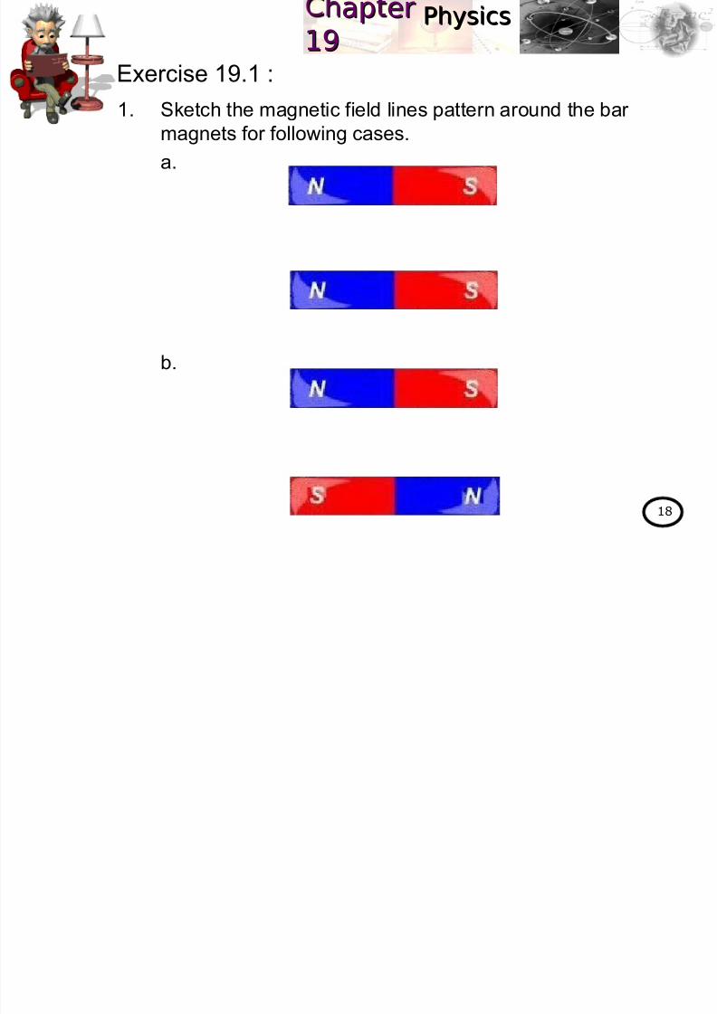
Exercise 19.1 :
1. Sketch the magnetic field lines pattern around the bar
magnets for following cases.
a.
b.
Ph iPh sicsap erap er

8/2/2019 4 Magnetic Field
http://slidepdf.com/reader/full/4-magnetic-field 19/102
PhysicsPhysicsap erap er1919
19
At the end of this chapter, students should be able to:At the end of this chapter, students should be able to:
ApplyApply magnetic field :magnetic field :
for a long straight wire,for a long straight wire,
for a circular coil,for a circular coil,
for a solenoid.for a solenoid.
Learning Outcome:
19.2 Magnetic produced by current-carryingconductor (1 hour)
r
I μ B
π=2
0
R I μ B
2
0=
nI μ B 0=
w w w .
k m p
h . m
a t ri k
. e d
u . m
y
w w w
.k m p
h . m
a t ri k
. e d
u . m
y
Ph iPhysicsap erap er

8/2/2019 4 Magnetic Field
http://slidepdf.com/reader/full/4-magnetic-field 20/102
PhysicsPhysicsap erap er1919
20
When a current flows in a conductor wirecurrent flows in a conductor wire or coilcoil, the
magnetic field will be producedmagnetic field will be produced.
The direction of magnetic fielddirection of magnetic field around the wire or coil can be
determined by using the right hand grip ruleright hand grip rule as shown inFigure 19.13.
19.2 Magnetic field produced by current –
carrying conductor
Figure 19.13Figure 19.13
Thumb – direction of currentdirection of currentOther fingers – direction of magneticdirection of magnetic
fieldfield (clockwiseclockwise OR
anticlockwiseanticlockwise)
Note:Note:
PhysicsPhysicsap erap er

8/2/2019 4 Magnetic Field
http://slidepdf.com/reader/full/4-magnetic-field 21/102
PhysicsPhysicsap erap er1919
21
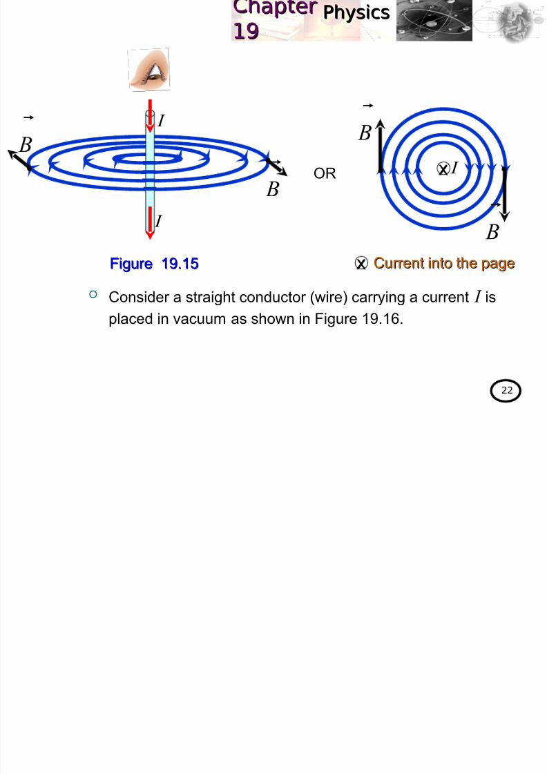
The magnetic field lines pattern around a straight conductor carrying current is shown in Figures 19.14 and 19.15.
19.2.1 Magnetic field of a long straight conductor
(wire) carrying current
OR
B
I
Current out of the pageCurrent out of the pageFigure 19.14Figure 19.14
B I
I B
B
PhysicsPhysicsap erap er
8/2/2019 4 Magnetic Field
http://slidepdf.com/reader/full/4-magnetic-field 22/102
PhysicsPhysicsap erap er1919
22
Consider a straight conductor (wire) carrying a current I is
placed in vacuum as shown in Figure 19.16.
OR
Figure 19.15Figure 19.15
I
I
I XX
Current into the pageCurrent into the pageXX
B
B
B
B
PhysicsPhysicsap erap er
8/2/2019 4 Magnetic Field
http://slidepdf.com/reader/full/4-magnetic-field 23/102
PhysicsPhysicsap erap er1919
23
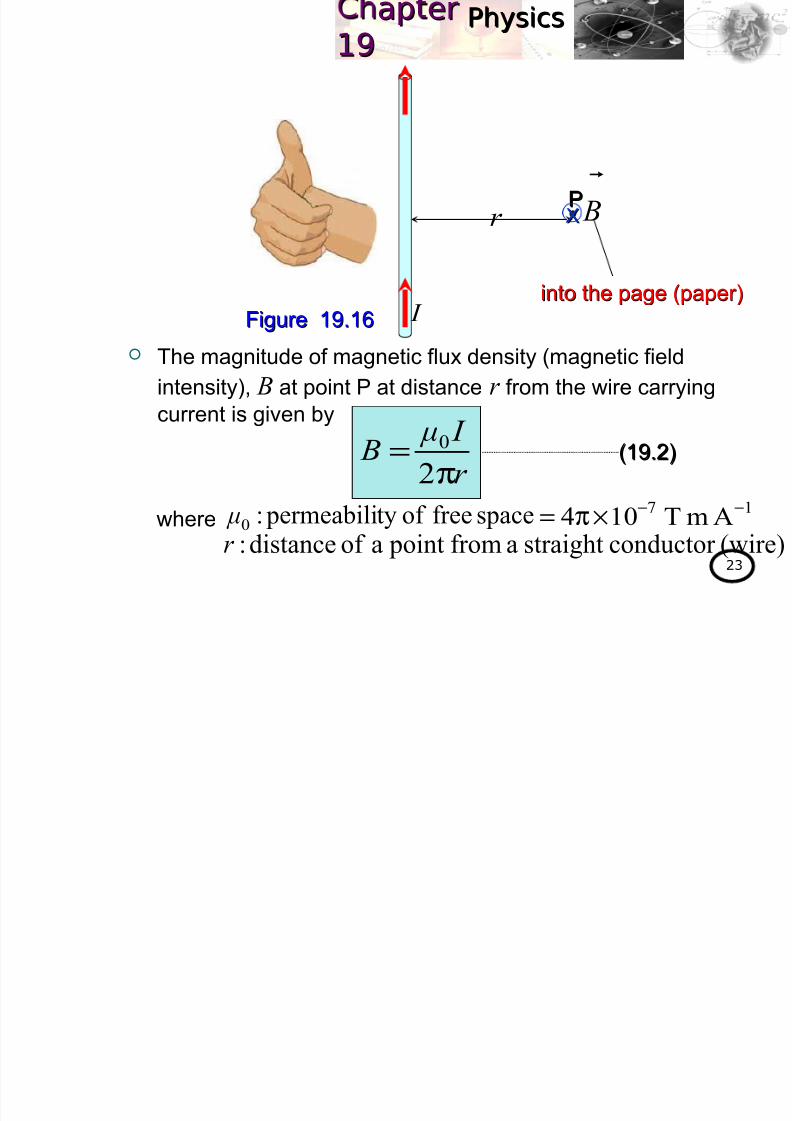
The magnitude of magnetic flux density (magnetic field
intensity), B at point P at distance r from the wire carrying
current is given by
r PP
I Figure 19.16Figure 19.16
XX B
into the page (paper)into the page (paper)
r
I μ B
π=2
0
where spacefreeof ty permeabili:0 μ 17AmT104
−−×π=
(wire)conductor straightafrom pointaof distance:r
(19.2)(19.2)
PhysicsPhysicsap erap er
8/2/2019 4 Magnetic Field
http://slidepdf.com/reader/full/4-magnetic-field 24/102
PhysicsPhysicsap erap er1919
24
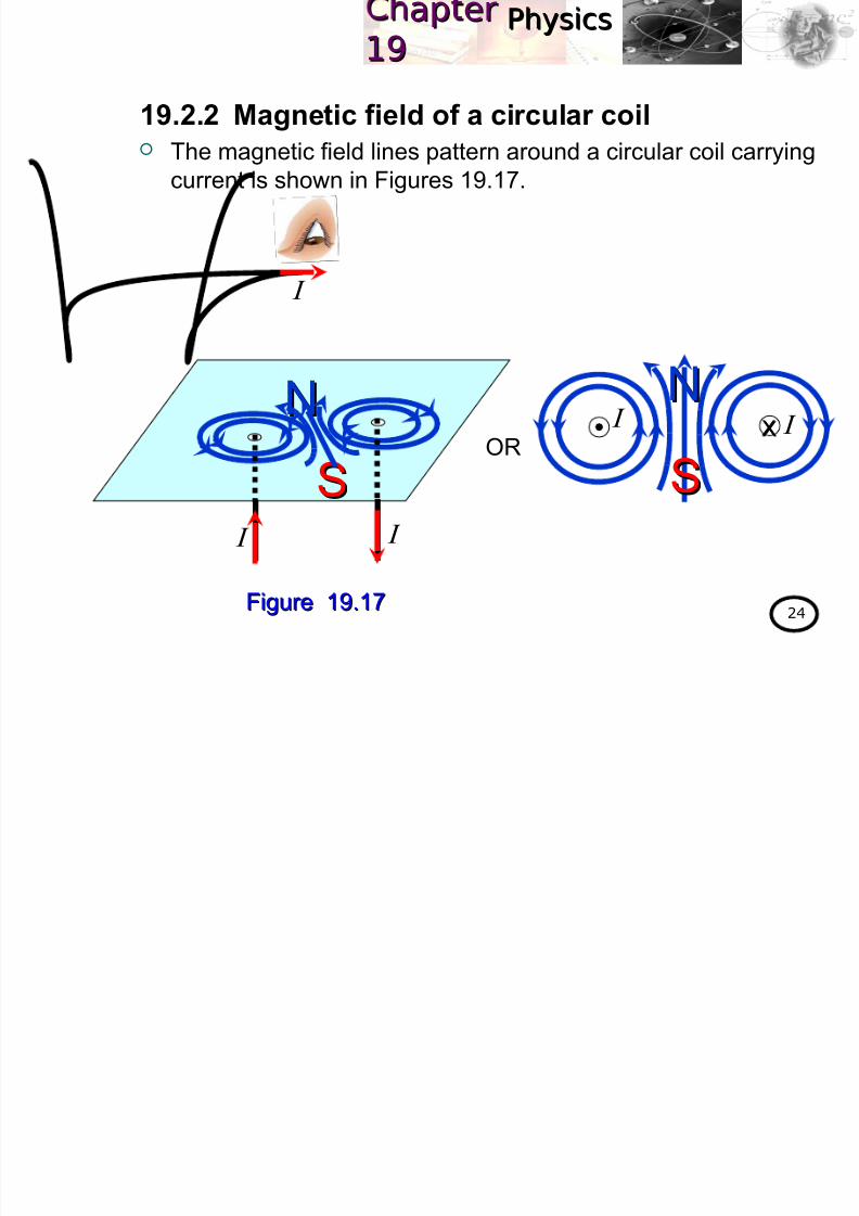
The magnetic field lines pattern around a circular coil carryingcurrent is shown in Figures 19.17.
19.2.2 Magnetic field of a circular coil
Figure 19.17Figure 19.17
I I XX
SS
NN
OR
SS
NN
I I
I
PhysicsPhysicsap erap er

8/2/2019 4 Magnetic Field
http://slidepdf.com/reader/full/4-magnetic-field 25/102
PhysicsPhysicsap erap er1919
25
Consider a circular shaped conductor with radius R that carries
a current I as shown in Figure 19.18.
R
NI μ B
2
0=
where
(19.3)(19.3)
The magnitude of magnetic fieldmagnetic field
intensityintensity B B at point O (centre of centre of
the circular coil or loopthe circular coil or loop) , is givenby
R
O
coilcircular theof radius: R
(loops)coilsof number : N
spacefreeof ty permeabili:0
μ
current: I Figure 19.18Figure 19.18
PhysicsPhysicsap erap er

8/2/2019 4 Magnetic Field
http://slidepdf.com/reader/full/4-magnetic-field 26/102
PhysicsPhysicsap erap er1919
26
A solenoid is an electrical device in which a long wire hasan electrical device in which a long wire has
been wound into a succession of closely spaced loops withbeen wound into a succession of closely spaced loops withgeometry of a helixgeometry of a helix.
The magnetic field lines pattern around a solenoid carrying
current is shown in Figure 19.19.
19.2.3 Magnetic field of a solenoid
SSNN
Figure 19.19Figure 19.19
I I
PhysicsPhysicsap erap er

8/2/2019 4 Magnetic Field
http://slidepdf.com/reader/full/4-magnetic-field 27/102
PhysicsPhysicsap erap er1919
27
OR
I
I XX XX XX XX
I
I
I
I
I
I
SSNN
PhysicsPhysicsap erap er

8/2/2019 4 Magnetic Field
http://slidepdf.com/reader/full/4-magnetic-field 28/102
PhysicsPhysicsap erap er1919
28
The magnitude of magnetic field intensity at the end of magnitude of magnetic field intensity at the end of N N
turn solenoidturn solenoid is given by
nI μ B 0
2
1= (19.5)(19.5)
where lengthunit per turnsof number :n
The magnitude of magnetic field intensity at the centre (mid-magnitude of magnetic field intensity at the centre (mid-
point/ inside) of point/ inside) of N N turn solenoidturn solenoid is given by
l
NI μ B 0=
nl
N =and
nI μ B 0= (19.4)(19.4)
PhysicsPhysicsap erap er

8/2/2019 4 Magnetic Field
http://slidepdf.com/reader/full/4-magnetic-field 29/102
PhysicsPhysicsap erap er1919
29
Two long straight wires are placed parallel to each other and
carrying the same current I . Sketch the magnetic field lines patternaround both wires
a. when the currents are in the same direction.
b. when the currents are in opposite direction.
Solution :Solution :
a.
Example 19.2 :
I
I I
I
PhysicsPhysicsap erap er

8/2/2019 4 Magnetic Field
http://slidepdf.com/reader/full/4-magnetic-field 30/102
PhysicsPhysicsap erap er1919
30
I I
OR
Solution :Solution :
a.
PhysicsPhysicsap erap er

8/2/2019 4 Magnetic Field
http://slidepdf.com/reader/full/4-magnetic-field 31/102
PhysicsPhysicsap erap er1919
31
OR
Solution :Solution :
b.
I I XX
I
I
I
I
PhysicsPhysicsap erap er
8/2/2019 4 Magnetic Field
http://slidepdf.com/reader/full/4-magnetic-field 32/102
PhysicsPhysicsap erap er1919
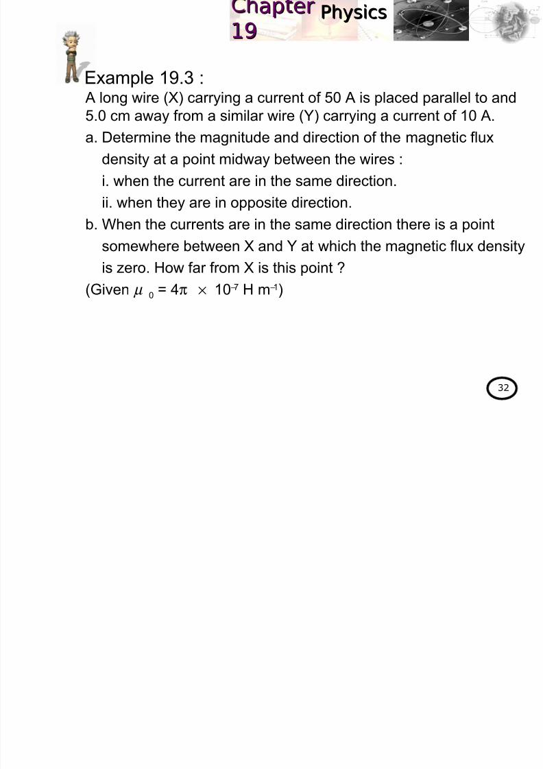
32
A long wire (X) carrying a current of 50 A is placed parallel to and5.0 cm away from a similar wire (Y) carrying a current of 10 A.
a. Determine the magnitude and direction of the magnetic flux
density at a point midway between the wires :
i. when the current are in the same direction.
ii. when they are in opposite direction.
b. When the currents are in the same direction there is a point
somewhere between X and Y at which the magnetic flux density
is zero. How far from X is this point ?
(Given µ 0 = 4π × 10−7 H m−1)
Example 19.3 :
PhysicsPhysicsap erap er

8/2/2019 4 Magnetic Field
http://slidepdf.com/reader/full/4-magnetic-field 33/102
PhysicsPhysicsap erap er1919
33
Solution :Solution :
a. i.
By using the equation of magnetic field at any point near the
straight wire, then at point A
Magnitude of BX :
A10m;100.5A;50 Y2
X =×== − I d I
T100.44
X−×= B
X B
Y B
OR
m105.22
2
YX
−×===d
r r
X I
AXr Yr
Y I
X
X0X
2πr
I μ B =
Direction : into the page OR upwards
( )( )2
7
X105.22
50104−
−
××
=π
π B
X B
Y B
X I Y I
d
Xr Yr A
PhysicsPhysicsap erap er

8/2/2019 4 Magnetic Field
http://slidepdf.com/reader/full/4-magnetic-field 34/102
PhysicsPhysicsap erap er1919
34
Solution :Solution :
a. i. Magnitude of BY :
Therefore the total magnetic flux density at point A is
A10m;100.5A;50 Y2
X =×== − I d I
T100.85
Y−×= B
Y
Y0Y
2πr
I μ B =
Direction : out of page OR downwards
( )( )2
7
Y105.22
10104−
−
××=
π
π B
YXA B B B
+=
YXA B B B +−=
Direction : into the pageDirection : into the page OR upwardsupwardsSign convention of Sign convention of B B:
Out of the page ⇒positive (+)
Into the page ⇒negative (−)
Note:Note:
54A 100.8100.4 −− ×+×−= B
T102.3 4A
−×−= B
PhysicsPhysicsap erap er

8/2/2019 4 Magnetic Field
http://slidepdf.com/reader/full/4-magnetic-field 35/102
PhysicsPhysicsap erap er1919
35
Solution :Solution :
a. ii.
By using the equation of magnetic field at any point near the
straight wire, then at point A
Magnitude of BX :
A10m;100.5A;50 Y2
X =×== − I d I
T100.44
X−×= B
X B
Y B
OR
Direction : into the page OR
upwards
( )( )2
7
X105.22
50104−
−
××
=π
π B
X I
AXr Yr
Y I XX
X B
Y B
X I Y I
d
Xr Yr A
PhysicsPhysicsap erap er

8/2/2019 4 Magnetic Field
http://slidepdf.com/reader/full/4-magnetic-field 36/102
PhysicsPhysicsap erap er1919
36
Solution :Solution :
a. ii. Magnitude of BY :
Therefore the resultant magnetic flux density at point A is
A10m;100.5A;50 Y2
X =×== − I d I
T100.85
Y−×= B
Direction : into the page OR upwards
( )( )2
7
Y105.22
10104−
−
××=
π
π B
YXA B B B
+=
YXA B B B −−=
Direction : into the pageDirection : into the page OR upwardsupwards
54A 100.8100.4 −− ×−×−= B
T108.4 4A
−×−= B
PhysicsPhysicsap erap er
8/2/2019 4 Magnetic Field
http://slidepdf.com/reader/full/4-magnetic-field 37/102
PhysicsPhysicsap erap er1919
37
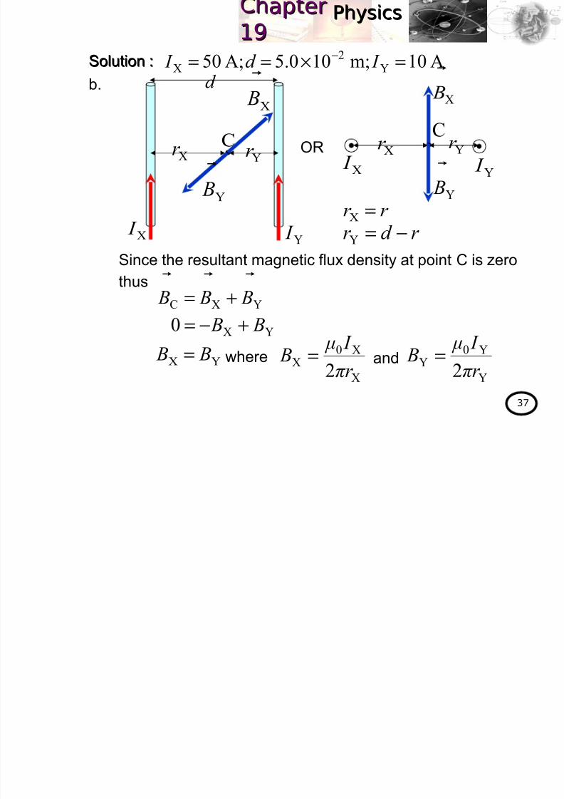
Solution :Solution :
b.
Since the resultant magnetic flux density at point C is zero
thus
A10m;100.5A;50 Y2
X =×== − I d I
X B
OR
r r =X
X I
CXr Yr
Y I
Y
B
r d r −=Y
YXC B B B
+=YX0 B B +−=
YX B B = where
X
X0X
2πr
I μ B = and
Y
Y0Y
2πr
I μ B =
X I Y I
d
Xr Yr C
X B
Y B
PhysicsPhysicsap erap er

8/2/2019 4 Magnetic Field
http://slidepdf.com/reader/full/4-magnetic-field 38/102
PhysicsPhysicsap erap er1919
38
Solution :Solution :
b.
Y
Y0
X
X0
22 πr I μ
πr I μ =
( )r d
I
r
I
−= YX
( )r r −×= −2100.5
1050
A10m;100.5A;50 Y2
X =×== − I d I
m102.4 2−×=r
PhysicsPhysicsap erap er

8/2/2019 4 Magnetic Field
http://slidepdf.com/reader/full/4-magnetic-field 39/102
Physicsyap erap er1919
39
Two long straight wires are oriented perpendicular to the page as
shown in Figure 19.20.
The current in one wire is I 1 = 3.0 A pointing into the page and the
current in the other wire is I 2= 4.0 A pointing out of page. Determine
the magnitude and direction of the nett magnetic field intensity at
point P.
(Given µ 0 = 4π × 10−7 H m−1)
Example 19.4 :
Figure 19.20Figure 19.20
PhysicsPhysicsap erap er

8/2/2019 4 Magnetic Field
http://slidepdf.com/reader/full/4-magnetic-field 40/102
Physicsyap erap er1919
40
Solution :Solution :
By applying the equation of magnetic field intensity for straight wire,thus
m100.5A;0.4A;0.3 2121
−×=== r I I
( ) ( )2
2
2
22 100.5100.5 −− ×+×=r
1r 2 B
2r
m101.72
2
−×=r θ
θ 2
2
2
1
101.7
100.5cos −
−
×
×==
r
r θ
704.0cos =θ
704.0101.7
100.5sin
2
2
=××
= −
−
θ
1
101
2πr
I μ B =
T1020.15
1−×= B
( )( )2
7
1100.52
0.3104−
−
××
=π
π B
1 B
1 I 2 I
P
XXm100.5
2−×
PhysicsPhysicsap erap er

8/2/2019 4 Magnetic Field
http://slidepdf.com/reader/full/4-magnetic-field 41/102
yyap erap er1919
41
Solution :Solution :
and
m100.5A;0.4A;0.3 2121
−×=== r I I
2
202
2πr
I μ B =
T1013.15
2−×= B
( )( )2
7
2101.72
0.4104−
−
××
= π
π B
Vector x-component (T) y-component (T)
Vector
sum
51 1020.1
−×= B1 B 0
θ B cos2−
2 B
( )( )704.01013.15−×−=6
1096.7−×−=
θ B sin2−( )( )704.01013.1
5−×−=61096.7 −×−=
651096.71020.1
−− ×−×= x B
6104.04
−×=
61096.70
−×−= y B
610.967
−×−=
PhysicsPhysicsap erap er

8/2/2019 4 Magnetic Field
http://slidepdf.com/reader/full/4-magnetic-field 42/102
yyap erap er1919
42
Solution :Solution :
Therefore the magnitude of the nett magnetic field intensity at point
P is given by
and its direction is
m100.5A;0.4A;0.3 2121
−×=== r I I
22
y x B B B +=
T1093.86−
×= B
( ) ( )2626 1096.71004.4 −− ×−+×=
= −
x
y
B
Bθ
1tan
1.63−=θ
××−= −
−−6
61
1004.4
1096.7tan
(297(297°° from +x-axis anticlockwise)from +x-axis anticlockwise) OR
1.63 B
1 B
2 B
P
PhysicsPhysicsap erap er

8/2/2019 4 Magnetic Field
http://slidepdf.com/reader/full/4-magnetic-field 43/102
yyap erap er1919
43
a. A closely wound circular coil of diameter 10 cm has 500 turns
and carries a current of 2.5 A. Determine the magnitude of the
magnetic field at the centre of the coil.
b. A solenoid of length 1.5 m and 2.6 cm in diameter carries a
current of 18 A. The magnetic field inside the solenoid is
2.3 mT. Calculate the length of the wire forming the solenoid.(Given µ 0 = 4π × 10−7 T m A−1)
Solution :Solution :
a. Given
By applying the equation for magnitude of the magnetic field at
the centre of the circular coil, thus
Example 19.5 :
A5.2;500m;105.02
1010 22
==×=×
= −−
I N R
R
NI μ B
2
0=
T1057.1 2−×= B
( )( )
( )2
7
100.52
5.2500104−
−
××
=π
B
PhysicsPhysicsap erap er

8/2/2019 4 Magnetic Field
http://slidepdf.com/reader/full/4-magnetic-field 44/102
yyap eap e1919
44
Solution :Solution :
b. Given
By applying the equation of magnetic flux density inside the
solenoid, thus
Since the shaped for each coil in the solenoid is circle, then the
circumference for one turn is
Therefore the length of the wire forming the solenoid is
l
NI μ Bi
0=
turns153= N
( ) ( )
5.1
18104103.2
73 N π −
− ×=×
T103.2m;103.1
2
106.2m;5.1 3
i2
2−−
−
×=×=×
== Br l
A18= I
πr 2ncecircumfere = ( )2103.12ncecircumfere −×= π
m1017.8ncecircumfere2−
×=( )ncecircumfere×= N L
( )2108.17153 −××= L
m5.12= L
PhysicsPhysicsap erap er
8/2/2019 4 Magnetic Field
http://slidepdf.com/reader/full/4-magnetic-field 45/102
yypp1919
45
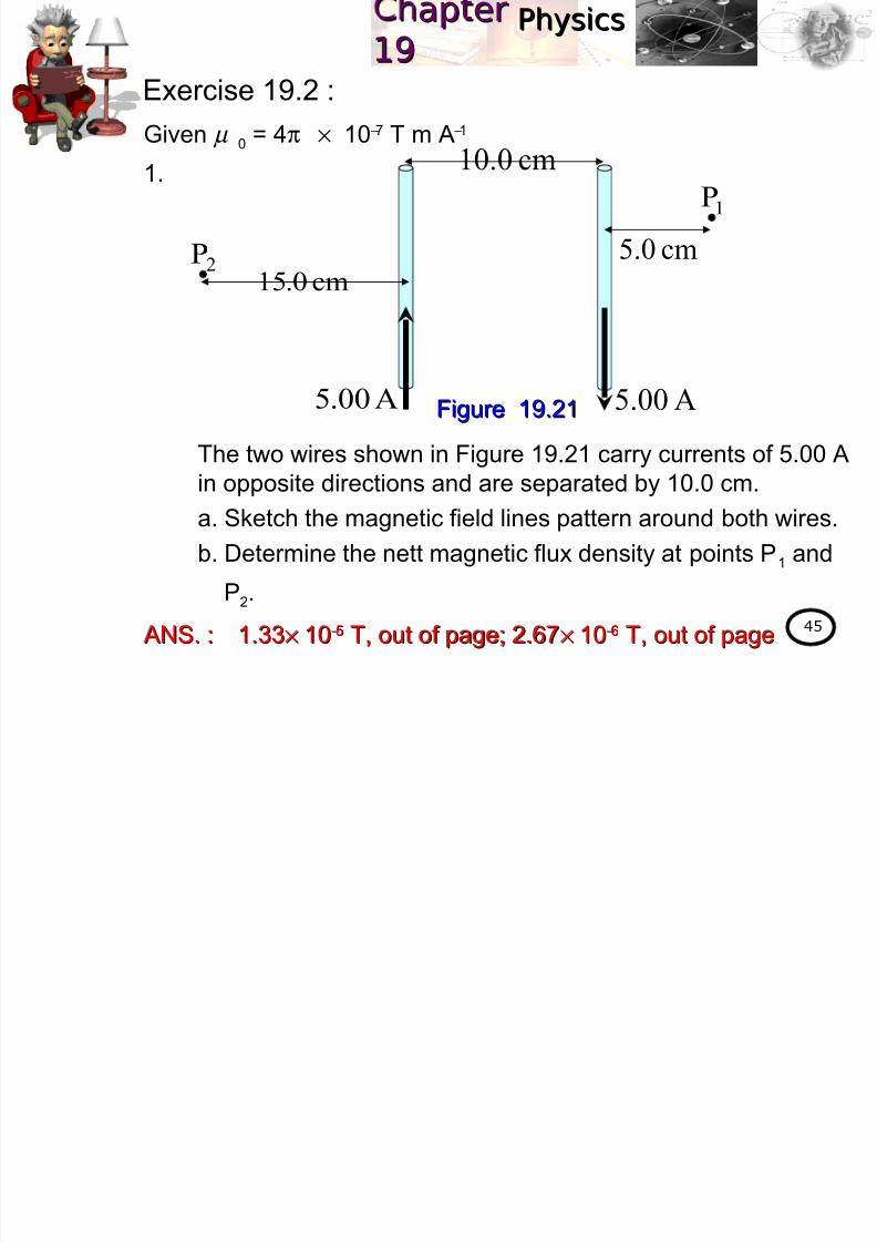
Exercise 19.2 :
Given µ 0 = 4π × 10−7 T m A−1
1.
The two wires shown in Figure 19.21 carry currents of 5.00 Ain opposite directions and are separated by 10.0 cm.
a. Sketch the magnetic field lines pattern around both wires.
b. Determine the nett magnetic flux density at points P1 and
P2.
ANS. :ANS. : 1.331.33×× 1010−−55 T, out of page; 2.67T, out of page; 2.67×× 1010−−66 T, out of pageT, out of page
Figure 19.21Figure 19.21A00.5 A00.5
cm0.10
cm0.15
cm0.52P
1P
PhysicsPhysicsap erap er

8/2/2019 4 Magnetic Field
http://slidepdf.com/reader/full/4-magnetic-field 46/102
yypp1919
46
2.
Four long, parallel power wires each carry 100 A current. A
cross sectional diagram for this wires is a square, 20.0 cm on
each side as shown in Figure 19.22.
a. Sketch the magnetic field lines pattern on the diagram.
b. Determine the magnetic flux density at the centre of the
square.
ANS. :ANS. : 4.04.0 ×× 1010−−44 T , to the left (180T , to the left (180°°))
Figure 19.22Figure 19.22
XX XX
PhysicsPhysicsap erap er9

8/2/2019 4 Magnetic Field
http://slidepdf.com/reader/full/4-magnetic-field 47/102
yypp1919
47
At the end of this chapter, students should be able to:At the end of this chapter, students should be able to:
UseUse force:force:
DescribeDescribe circular motion of a charge in a uniformcircular motion of a charge in a uniform
magnetic field.magnetic field.
UseUse relationshiprelationship F F BB== F F
CC..
Learning Outcome:
19.3 Force on a moving charged particle in a
uniform magnetic field (1 hour)
( ) Bvq F
×=
w w w
.k m p
h . m
a t ri k
. e d
u . m
y
w w w
.k m p
h . m
a t ri k
. e d
u . m
y
PhysicsPhysicsap erap er19

8/2/2019 4 Magnetic Field
http://slidepdf.com/reader/full/4-magnetic-field 48/102
pp1919
48
19.3.1 Magnetic force A stationarystationary electric charge in a magnetic field will notnot
experience a magnetic forceexperience a magnetic force. But if the charge is movingcharge is moving with
a velocity, v in a magnetic field, B then it will experience ait will experience a
magnetic forcemagnetic force. The magnitudemagnitude of the magnetic force can be calculated by
using the following equation:
19.3 Force on a moving charged particle
in a uniform magnetic field
θ qvB F sin=
where forcemagnetic: F densityfluxmagnetic: B
chargeaof velocity:vchargetheof magnitude:q
Bvθ
and betweenangle:
(19.6)(19.6)
PhysicsPhysicsap erap er919

8/2/2019 4 Magnetic Field
http://slidepdf.com/reader/full/4-magnetic-field 49/102
pp1919
49
B
v
F
Figure 19.23Figure 19.23
In vector formvector form,
The direction of the magnetic force can be determined by using
the Fleming’s hand rule.
Fleming’s right handFleming’s right hand rule for negativenegative charge
Fleming’s left handFleming’s left hand rule for positivepositive charge
(19.7)(19.7)( ) Bvq F
×=
B
v
F
shown in
Figures
19.23 and
19.24
ThumbThumb – direction of – direction of ForceForce
First finger First finger – direction of – direction of FieldField
Second finger Second finger – direction of – direction of VelocityVelocity
Figure 19.24Figure 19.24Note:Note:
PhysicsPhysicsap erap er1919
8/2/2019 4 Magnetic Field
http://slidepdf.com/reader/full/4-magnetic-field 50/102
pp1919
50
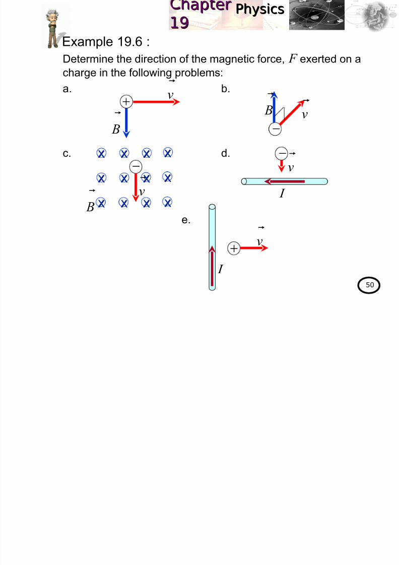
Determine the direction of the magnetic force, F exerted on a
charge in the following problems:a. b.
c. d.
e.
Example 19.6 :
+
B
v
−
B
v
XX XX XX XX
XX XX XX XX
XX XX XX XX
v
+
I
I
−v
− B
v
PhysicsPhysicsap erap er1919

8/2/2019 4 Magnetic Field
http://slidepdf.com/reader/full/4-magnetic-field 51/102
pp1919
51
Solution :Solution :
a. By using Fleming’s left hand rule, thus
b. By using Fleming’s right hand rule, thus
c. By using Fleming’s right hand rule, thus
+
B
v
(into the page)(into the page) F
− B
v
F
(to the left)(to the left)
−
B
v
XX XX XX XX
XX XX XX XX
XX XX XX XX
F
(to the left)(to the left)
PhysicsPhysicsap erap er1919
8/2/2019 4 Magnetic Field
http://slidepdf.com/reader/full/4-magnetic-field 52/102
pp1919
52
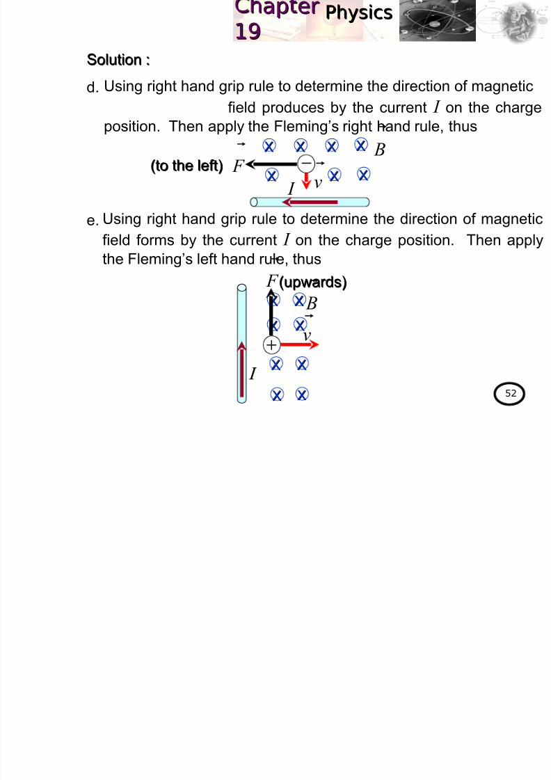
Solution :Solution :
d.
e. I
−v
B
XX XX XX XX
XX XX XX F
(to the left)(to the left)
Using right hand grip rule to determine the direction of magnetic
field produces by the current I on the charge
position. Then apply the Fleming’s right hand rule, thus
Using right hand grip rule to determine the direction of magnetic
field forms by the current I on the charge position. Then apply
the Fleming’s left hand rule, thus
v
+
I
(upwards)(upwards)
B
XXXX
XX
XX
XX
XX
XX XX
F
PhysicsPhysicsap erap er1919

8/2/2019 4 Magnetic Field
http://slidepdf.com/reader/full/4-magnetic-field 53/102
pp1919
53
Calculate the magnitude of the force on a proton travelling
5.0× 10⁷
m s−1
in the uniform magnetic flux density of 1.5 Wb m−2
, if :a. the velocity of the proton is perpendicular to the magnetic field.
b. the velocity of the proton makes an angle 50°with the magnetic
field.
(Given the charge of the proton is +1.60× 10⁻¹⁹ C)
Solution :Solution :
a. Given
Therefore
b. Given
Hence
Example 19.7 :
90=θ
217 mWb5.1;sm105.0 −− =×= Bv
θ qvB F sin=( )( )( ) 90sin5.1100.51060.1 719 ××= −
N1020.1 11−×= F 50=θ
N1019.9
12−
×= F
( )( )( ) 50sin5.1100.51060.1 719 ××= − F
PhysicsPhysicsap erap er9
8/2/2019 4 Magnetic Field
http://slidepdf.com/reader/full/4-magnetic-field 54/102
pp1 91 9
54
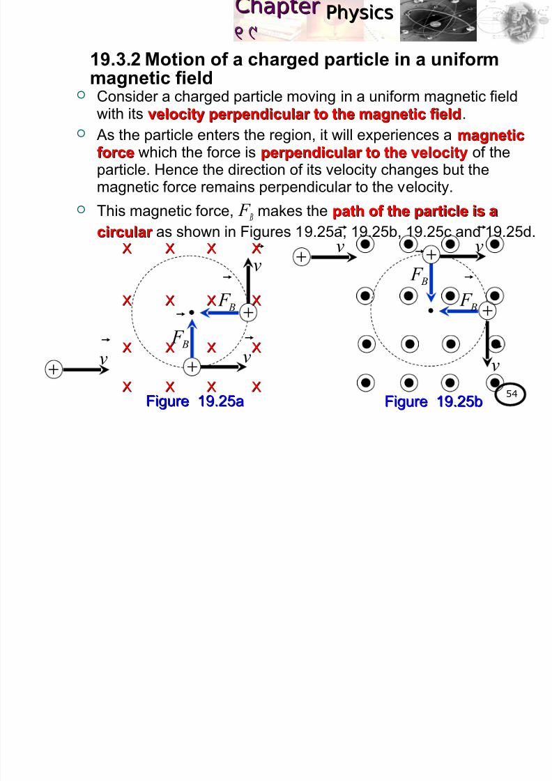
Consider a charged particle moving in a uniform magnetic fieldwith its velocity perpendicular to the magnetic fieldvelocity perpendicular to the magnetic field.
As the particle enters the region, it will experiences a magneticmagnetic
forceforce which the force is perpendicular to the velocityperpendicular to the velocity of theparticle. Hence the direction of its velocity changes but themagnetic force remains perpendicular to the velocity.
This magnetic force, F B
makes the path of the particle is apath of the particle is a
circular circular as shown in Figures 19.25a, 19.25b, 19.25c and 19.25d.
19.3.2 Motion of a charged particle in a uniformmagnetic field
Figure 19.25aFigure 19.25a
+ v
v
+ B F
+
v
B F
XX XX XX XX
XX XX XX XX
XX XX XX XX
XX XX XX XX
+ v
v
+ B F
+
v
B F
Figure 19.25bFigure 19.25b
PhysicsPhysicsap erap er1919

8/2/2019 4 Magnetic Field
http://slidepdf.com/reader/full/4-magnetic-field 55/102
1919
55
Since the path is a circle therefore the magnetic force F B
contributes the centripetal force F c (nett force) in this motion.
Thus
Figure 19.25cFigure 19.25c Figure 19.25dFigure 19.25d
− v
v
− B F
−
v
B F
− v
v
−
B F
−
v
B F
XX XX XX XX
XX XX XX XX
XX XX XX XX
XX XX XX XX
c B F F =
r
mvθ qvB
2
sin = 90=θ and
PhysicsPhysicsap erap er1919

8/2/2019 4 Magnetic Field
http://slidepdf.com/reader/full/4-magnetic-field 56/102
1919
56
The period of the circular motion, T makes by the particle isgiven by
And the frequency of the circular motion is
Bq
mvr =
where particlechargedtheof mass:mvelocitytheof magnitude:v
pathcircular theof radius:r particlechargedtheof magnitude:q
(19.8)(19.8)
ω r v =
T
r v
π 2=
T
π ω
2=and
Bq
mT
π 2=
Bq
mvr =and
v
r T
π 2=
(19.9)(19.9)
T
f 1
=
PhysicsPhysicsap erap er1919
8/2/2019 4 Magnetic Field
http://slidepdf.com/reader/full/4-magnetic-field 57/102
1919
57
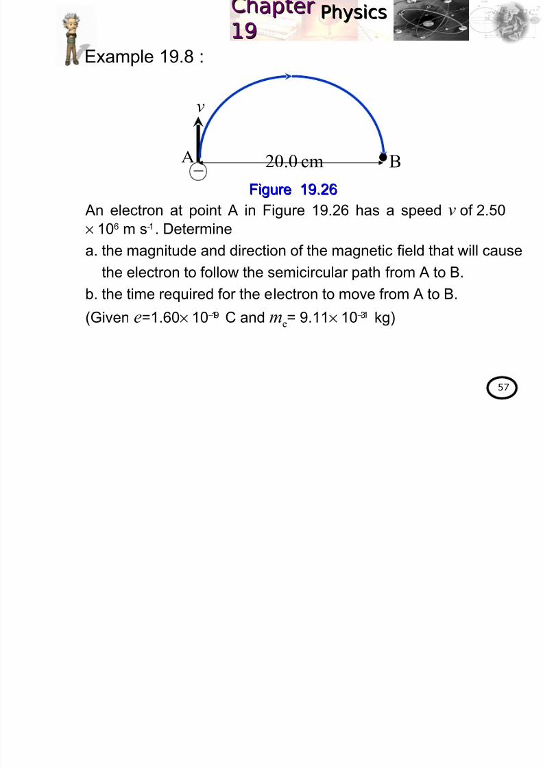
An electron at point A in Figure 19.26 has a speed v of 2.50
× 106 m s-1. Determine
a. the magnitude and direction of the magnetic field that will cause
the electron to follow the semicircular path from A to B.
b. the time required for the electron to move from A to B.
(Given e=1.60× 10⁻¹⁹ C and me= 9.11× 10⁻³¹ kg)
Example 19.8 :
−
v
BA cm0.20
Figure 19.26Figure 19.26
PhysicsPhysicsap erap er1919
8/2/2019 4 Magnetic Field
http://slidepdf.com/reader/full/4-magnetic-field 58/102
1919
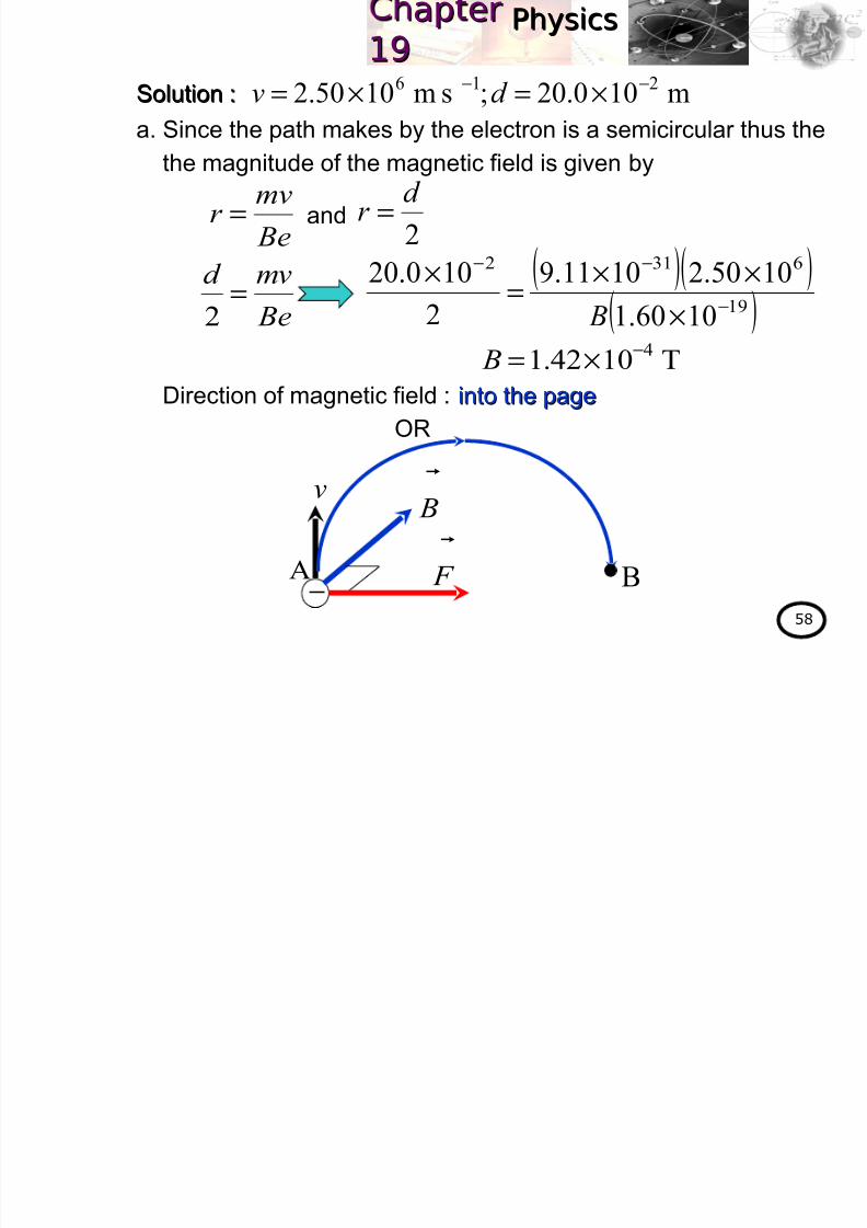
58
Solution :Solution :
a. Since the path makes by the electron is a semicircular thus the
the magnitude of the magnetic field is given by
Direction of magnetic field : into the pageinto the page
OR
m100.20;sm1050.2 216 −− ×=×= d v
Be
mvr =
T1042.14−×= B
2
d r =
Be
mvd =
2
( )( )
( )19
6312
1060.1
1050.21011.9
2
100.20
−
−−
×
××=
×
B
and
−
v
BA
B
F
PhysicsPhysicsap erap er1919

8/2/2019 4 Magnetic Field
http://slidepdf.com/reader/full/4-magnetic-field 59/102
1919
59
Solution :Solution :
b. The period of the electron is
Since the path is the semicircular then the time required for the
electron moves from A to B is given by
m100.20;sm1050.2 216 −− ×=×= d v
rωv =
s1051.27−
×=T
T π ω 2=
=
T
π d v
2
2
( )T
π 26 100.20
1050.2−×
=×
and
T t 2
1=
( )71051.22
1 −×=t
s1026.1 7−×=t
PhysicsPhysicsap erap er1919

8/2/2019 4 Magnetic Field
http://slidepdf.com/reader/full/4-magnetic-field 60/102
1919
60
Exercise 19.3 :1. Determine the sign of a charge in the following problems.
a. b.
ANS. :ANS. : positive; positivepositive; positive
2. Determine the direction of the magnetic force exerted on a
positive charge in each problem below when a switch S isclosed.
a. b.
ANS. :ANS. : into the page; out of pageinto the page; out of page
B
v
F
B
v F
Switch, S
+ v
Switch, S
+v
PhysicsPhysicsap erap er1919
8/2/2019 4 Magnetic Field
http://slidepdf.com/reader/full/4-magnetic-field 61/102
1919
61
3. An electron experiences the greatest force as it travels
2.9× 10⁶ m s−1 in a magnetic field when it is moving north. The
force is upward and of magnitude 7.2× 10⁻¹³ N. Determine the
magnitude and direction of the magnetic field.
(Given the charge of the electron is 1.60× 10⁻¹⁹ C)
(Physics for scientists & engineers ,3(Physics for scientists & engineers ,3rdrd edition, Giancoli, Q22, p.705)edition, Giancoli, Q22, p.705)
ANS. :ANS. : 1.6 T to the east1.6 T to the east4. An electron moving with a speed of 9.1× 10⁵ m s−1 in the
positive x direction experiences zero magnetic force. When it
moves in the positive y direction, it experiences a force of
2.0× 10⁻¹³ N that points in the negative z direction. What is the
direction and magnitude of the magnetic field?
(Given e=1.60× 10⁻¹⁹ C and me= 9.11× 10⁻³¹ kg)
(Physics, 3(Physics, 3rdrd edition, James S. Walker, Q8, p.762)edition, James S. Walker, Q8, p.762)
ANS. :ANS. : 1.37 T to the left (in the negative1.37 T to the left (in the negative y y direction)direction)
PhysicsPhysicsap erap er1919

8/2/2019 4 Magnetic Field
http://slidepdf.com/reader/full/4-magnetic-field 62/102
1919
62
5. Two charged particles with different speeds move one at a
time through a region of uniform magnetic field. The particles
move in the same direction and experience equal magnetic
forces.
a. If particle 1 has four times the charge of particle 2, which
particle has the greater speed? Explain.
b. Calculate the ratio of the speeds, v1/v2.(Physics, 3(Physics, 3rdrd edition, James S. Walker, Q9, p.762)edition, James S. Walker, Q9, p.762)
ANS. :ANS. : 1/41/4
6. A 12.5 µ C particle of mass 2.80× 10⁻⁵ kg moves
perpendicular to a 1.01 T magnetic field in a circular path of
radius 26.8 m.
a. How fast is the particle moving?
b. How long will it take the particle to complete one orbit?
(Physics, 3(Physics, 3rdrd edition, James S. Walker, Q18, p.763)edition, James S. Walker, Q18, p.763)
ANS. :ANS. : 12.1 m s12.1 m s−−11
; 13.9 s; 13.9 s
PhysicsPhysicsap erap er1919

8/2/2019 4 Magnetic Field
http://slidepdf.com/reader/full/4-magnetic-field 63/102
1919
63
At the end of this chapter, students should be able to:At the end of this chapter, students should be able to:
UseUse force:force:
Learning Outcome:
19.4 Force on a current-carrying conductor in a
uniform magnetic field (1 hour)
( ) Bl I F
×=
w w w
.k m p
h . m
a t ri k
. e d
u . m
y
w w w
.k m p
h . m
a t ri k
. e d
u . m
y
PhysicsPhysicsap erap er1919

8/2/2019 4 Magnetic Field
http://slidepdf.com/reader/full/4-magnetic-field 64/102
1919
64
When a current-carrying conductor current-carrying conductor is placed in a magneticin a magnetic
fieldfield B, thus a magnetic force will acts on that conductor magnetic force will acts on that conductor .
The magnitudemagnitude of the magnetic force exerts on the current-carrying conductor is given by
In vector formvector form,
19.4 Force on a current-carrying
conductor in a uniform magnetic field
θ IlB F sin= (19.10)(19.10)
( ) Bl I F
×= (19.11)(19.11)
where forcemagnetic: F densityfluxmagnetictheof magnitude: B
current: I conductor theof length:l
B I θ
andof direction betweenangle:
PhysicsPhysicsap erap er1919
8/2/2019 4 Magnetic Field
http://slidepdf.com/reader/full/4-magnetic-field 65/102
1919
65
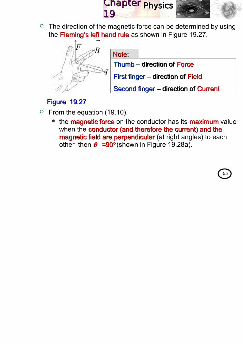
The direction of the magnetic force can be determined by using
the Fleming’s left hand ruleFleming’s left hand rule as shown in Figure 19.27.
From the equation (19.10),
the magnetic forcemagnetic force on the conductor has its maximummaximum value
when the conductor (and therefore the current) and theconductor (and therefore the current) and themagnetic field are perpendicular magnetic field are perpendicular (at right angles) to eachother then θ θ ==9090°° (shown in Figure 19.28a).
ThumbThumb – direction of – direction of ForceForce
First finger First finger – direction of – direction of FieldField
Second finger Second finger – direction of – direction of CurrentCurrent
Figure 19.27Figure 19.27
Note:Note: B
I
F
PhysicsPhysicsap erap er1919

8/2/2019 4 Magnetic Field
http://slidepdf.com/reader/full/4-magnetic-field 66/102
1919
66
the magnetic forcemagnetic force on the conductor is zerozero when theconductor (and therefore the current) is parallel to theconductor (and therefore the current) is parallel to the
magnetic fieldmagnetic field then θ θ =0=0°° (shown in Figure 19.28b).
Figure 19.28aFigure 19.28a
IlB F =max
B
90=θ
I
90sinmax IlB F =
B
0=θ
I
Figure 19.28bFigure 19.28b
0= F
0sin IlB F =
One teslaOne tesla is defined as the magnetic flux density of a field in which aas the magnetic flux density of a field in which a
force of 1 newton acts on a 1 metre length of a conductor which carryingforce of 1 newton acts on a 1 metre length of a conductor which carrying
a current of 1 ampere and is perpendicular to the field.a current of 1 ampere and is perpendicular to the field.
Note:Note:
PhysicsPhysicsap erap er1919

8/2/2019 4 Magnetic Field
http://slidepdf.com/reader/full/4-magnetic-field 67/102
1919
67
Determine the direction of the magnetic force, exerted on a current-
carrying conductor in the following cases.a. b.
Solution :Solution :
For both cases, use Fleming’s left hand rule :
a.
Example 19.9 :
B I
XX XX XX XX
XX XX XX XX
XX XX XX XX B
I
XX XX XX XX
XX XX XX XX
XX XX XX XX
B I
XX XX XX XX
XX XX XX XX
XX XX XX XX
F
(to the left)(to the left)
b.
B I
XX XX XX XX
XX XX XX XX
XX XX XX XX
F
(to the right)(to the right)
PhysicsPhysicsap erap er1919

8/2/2019 4 Magnetic Field
http://slidepdf.com/reader/full/4-magnetic-field 68/102
1919
68
A wire of 100 cm long is placed perpendicular to the magnetic field
of 1.20 Wb m−2
.a. Calculate the magnitude of the force on the wire when a current
of 15 A is flowing.
b. For the same current in (a), determine the magnitude of the force
on the wire when its length is extended to 150 cm.
c. If the force on the wire in part (b) is 60× 10−2 N and the current
flows is 12 A, calculate the magnitude of magnetic field was
supplied.
Solution :Solution :
a. Given
Example 19.10 :
90;mWb20.1;m00.1 2 === − θ Bl
A15= I θ IlB F sin=
( )( )( ) 90sin20.100.115= N18= F
PhysicsPhysicsap erap er1919

8/2/2019 4 Magnetic Field
http://slidepdf.com/reader/full/4-magnetic-field 69/102
1919
69
Solution :Solution :
b. Given
The magnitude of the magnetic force on the wire is given by
c. Given
The magnitude of the magnetic field is given by
m501A;15 .l I ==
θ IlB F sin=( )( )( ) 90sin20.150.115=
N27= F
N1060m;501A;12 2−×=== F .l I
θ IlB F sin=
( )( )
90sin50.1121060
2 B
=×
−
T1033.3 2−×= B
PhysicsPhysicsap erap er1919
8/2/2019 4 Magnetic Field
http://slidepdf.com/reader/full/4-magnetic-field 70/102
1919
70
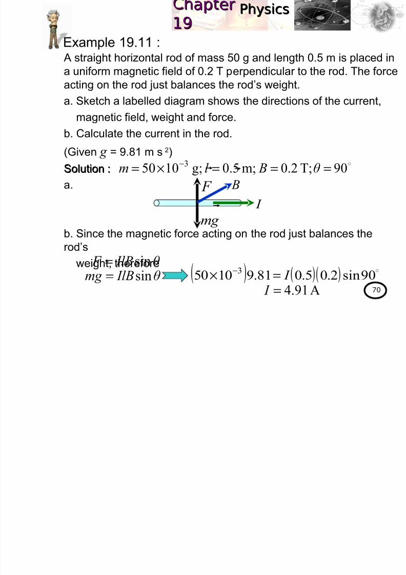
A straight horizontal rod of mass 50 g and length 0.5 m is placed in
a uniform magnetic field of 0.2 T perpendicular to the rod. The forceacting on the rod just balances the rod’s weight.
a. Sketch a labelled diagram shows the directions of the current,
magnetic field, weight and force.
b. Calculate the current in the rod.
(Given g = 9.81 m s−2)
Solution :Solution :
a.
b. Since the magnetic force acting on the rod just balances the
rod’s
weight, therefore
Example 19.11 :
90;T2.0;m5.0g;1050 3 ===×= − θ Bl m
θ IlB F sin=θ IlBmg sin=
A91.4= I
( ) ( )( ) 90sin2.05.081.91050
3 I =× −
I
F
g m
B
PhysicsPhysicsap erap er1919

8/2/2019 4 Magnetic Field
http://slidepdf.com/reader/full/4-magnetic-field 71/102
1919
71
At the end of this chapter, students should be able to:At the end of this chapter, students should be able to:
DeriveDerive force per unit length of two parallel current-force per unit length of two parallel current-
carrying conductors.carrying conductors.
UseUse force per unit length:force per unit length:
DefineDefine one ampere.one ampere.
Learning Outcome:
19.5 Forces between two parallel current-
carrying conductors (1 hour)
πd
I I μ
l
F
2
210=
w w w
.k m p
h . m
a t ri k
. e d
u . m
y
w w w
.k m p
h . m
a t ri k
. e d
u . m
y
PhysicsPhysicsap erap er191919 5 Forces between two parallel current

8/2/2019 4 Magnetic Field
http://slidepdf.com/reader/full/4-magnetic-field 72/102
1919
72
19.5.1 Force per unit length Consider two identical straight conductors 1 and 2 carrying
currents I 1and I
2with length l are placed parallel to each other
as shown in Figure 19.29.
19.5 Forces between two parallel current-
carrying conductors
Figure 19.29Figure 19.29
d
1 21 I
1 I
2 I
2 I
P1 B
12 F
21 F
Q
2 B
PhysicsPhysicsap erap er1919

8/2/2019 4 Magnetic Field
http://slidepdf.com/reader/full/4-magnetic-field 73/102
1919
73
The conductors are in vacuum and their separation is d .
The magnitude of the magnetic flux density, B1 at point P on the
conductor 2 due to the current in the conductor 1 is given by
Conductor 2 carries a current I 2 and in the magnetic field B1
thus the conductor 2 will experiences a magnetic force, F 12 . The magnitude of F 12 is given by
d
I B
π
µ
2
101 = Direction : into the page
θ sin1212 lB I F = 90=θ and
90sin2
10
2
= d
I
l I π
µ
d
l I I F
π
µ
2
21012 =
PhysicsPhysicsap erap er1919
8/2/2019 4 Magnetic Field
http://slidepdf.com/reader/full/4-magnetic-field 74/102
1919
74
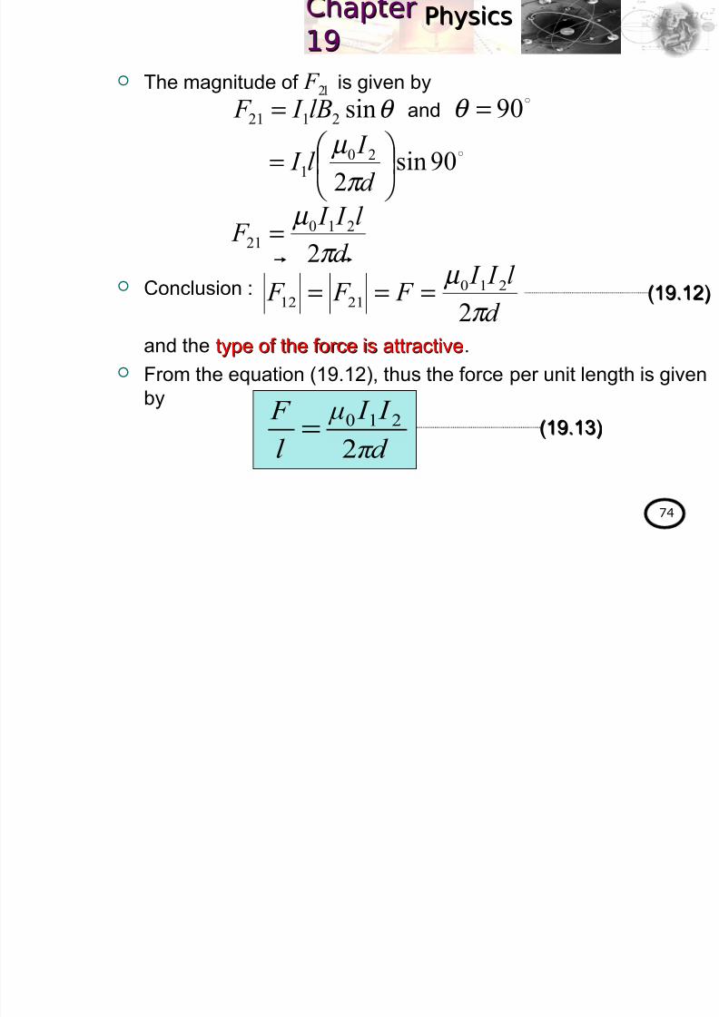
The magnitude of F 21 is given by
Conclusion :
and the type of the force is attractivetype of the force is attractive.
From the equation (19.12), thus the force per unit length is given
by
θ sin2121 lB I F = 90=θ and
90sin2
201
=
d
I l I
π
µ
d
l I I F
π
µ
2
21021 =
d
l I I F F F
π
µ
2
2102112 ===
(19.12)(19.12)
πd
I I μ
l
F
2
210= (19.13)(19.13)
PhysicsPhysicsap erap er1919

8/2/2019 4 Magnetic Field
http://slidepdf.com/reader/full/4-magnetic-field 75/102
1919
75
If the direction of current in the conductor 2 is change to upside
down as shown in Figure 19.30.
The magnitude of F 12 and F 21 can be determined by using the
eq. (19.12) and their direction can be determined by applyingFleming’s left hand rule.
Conclusion : Type of the force is repulsiveType of the force is repulsive.
Figure 19.30Figure 19.30
2 I
2 I
1 I
1 I d
1 2Note:Note:
The currents are in the
same directionsame direction – 2
conductors attractattract
each other.
The currents are inopposite directionopposite direction – 2
conductors repelrepel each
other.21 F Q 2
B
12 F 1 B
P
PhysicsPhysicsap erap er1919
8/2/2019 4 Magnetic Field
http://slidepdf.com/reader/full/4-magnetic-field 76/102
1919
76
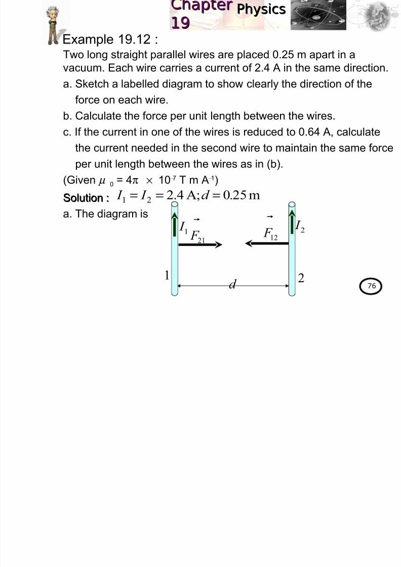
Two long straight parallel wires are placed 0.25 m apart in a
vacuum. Each wire carries a current of 2.4 A in the same direction.
a. Sketch a labelled diagram to show clearly the direction of the
force on each wire.
b. Calculate the force per unit length between the wires.
c. If the current in one of the wires is reduced to 0.64 A, calculate
the current needed in the second wire to maintain the same force
per unit length between the wires as in (b).
(Given µ 0 = 4π × 10−7 T m A−1)
Solution :Solution :
a. The diagram is
Example 19.12 :
12 F
21 F
d
1
1 I
2
2 I
m250A;4.221 .d I I ===
PhysicsPhysicsap erap er1919

8/2/2019 4 Magnetic Field
http://slidepdf.com/reader/full/4-magnetic-field 77/102
199
77
Solution :Solution :
b. The force per unit length between the wires is given by
c. Given
Therefore the current needed in the second wire is
m250A;4.221 .d I I ===
πd I I μ
l F
2
210= ( )( )( )
( )25.024.24.2104 7
π π
l F
−
×=
16 m N106.4 −−×=
l
F
A64.01 = I
πd
I I μ
l
F
2
210=
( )( )( )25.02
64.0104106.4 2
76
π
I π −
− ×=×
A98.82 = I
PhysicsPhysicsap erap er1919
8/2/2019 4 Magnetic Field
http://slidepdf.com/reader/full/4-magnetic-field 78/102
19
78
From the eq. (19.13), if two long straight parallel conductors are
placed 1.0 m apart in a vacuum and carry equal currents of
1.0 A thus the force per unit length that each conductor exerts
on each other is given by
The ampereThe ampere is defined as the constant current, whichthe constant current, whichflowing in each of two infinitely long parallel straightflowing in each of two infinitely long parallel straight
conductors of negligible of cross sectional area separatedconductors of negligible of cross sectional area separated
by a distance of 1.0 metre in vacuum, would produce aby a distance of 1.0 metre in vacuum, would produce a
force per unit length between the conductors of force per unit length between the conductors of
2.02.0× 1010−77
N mN m− 11..
19.5.2 The ampere
πd
I I μ
l
F
2
210=
( )( ) ( )( )12
11104 7
π
π −×
=
17 m N100.2 −−×=
l
F
PhysicsPhysicsap erap er1919

8/2/2019 4 Magnetic Field
http://slidepdf.com/reader/full/4-magnetic-field 79/102
19
79
Exercise 19.4 :Given µ 0 = 4π × 10−7 T m A−1
1. A vertical straight conductor Y of length 0.5 m is situated in auniform horizontal magnetic field of 0.1 T.
a. Sketch a labelled diagram to show the directions of the
current, field and force.
b. Calculate the force on Y when a current of 4 A is passed
into it.c. Through what angle must Y be turned in a vertical plane
so that the force on Y is halved?
(Advanced level physics, 7(Advanced level physics, 7thth edition, Nelkon&Parker, Q6, p.336)edition, Nelkon&Parker, Q6, p.336)
ANS. :ANS. : 0.2 N; 600.2 N; 60°°
2. A current-carrying conductor experiences no magnetic force
when it is placed in a uniform magnetic field. Explain the
statement.
PhysicsPhysicsap erap er1919

8/2/2019 4 Magnetic Field
http://slidepdf.com/reader/full/4-magnetic-field 80/102
80
At the end of this chapter, students should be able to:At the end of this chapter, students should be able to:
UseUse torque:torque:
wherewhere N N = number of turns= number of turns
ExplainExplain the working principles of a moving coilthe working principles of a moving coil
galvanometer.galvanometer.
Learning Outcome:
19.6 Torque on a coil (1 hour)
( ) B A NI τ
×=
w w w
.k m p
h . m
a t ri k
. e d
u . m
y
w w w
.k m p
h . m
a t ri k
. e d
u . m
y
PhysicsPhysicsap erap er1919

8/2/2019 4 Magnetic Field
http://slidepdf.com/reader/full/4-magnetic-field 81/102
81
19.6.1 Formula of torque
Consider a rectangular coil (loop) of wire with side lengths a and
b that it can turn about axis PQ. The coil is in a magnetic field of
flux density B and the plane of the coil makes an angle θ withthe direction of the magnetic field. A current I is flowing round
the coil as shown in Figure 19.31a.
19.6 Torque on a coil
PhysicsPhysicsap erap er1919

8/2/2019 4 Magnetic Field
http://slidepdf.com/reader/full/4-magnetic-field 82/102
82
Q
P
b
a
Figure 19.31aFigure 19.31a
θ
B B
B
B
B F
F
1 F
I I
I
I 1 F
A
φ
PhysicsPhysicsap erap er1919
8/2/2019 4 Magnetic Field
http://slidepdf.com/reader/full/4-magnetic-field 83/102
83
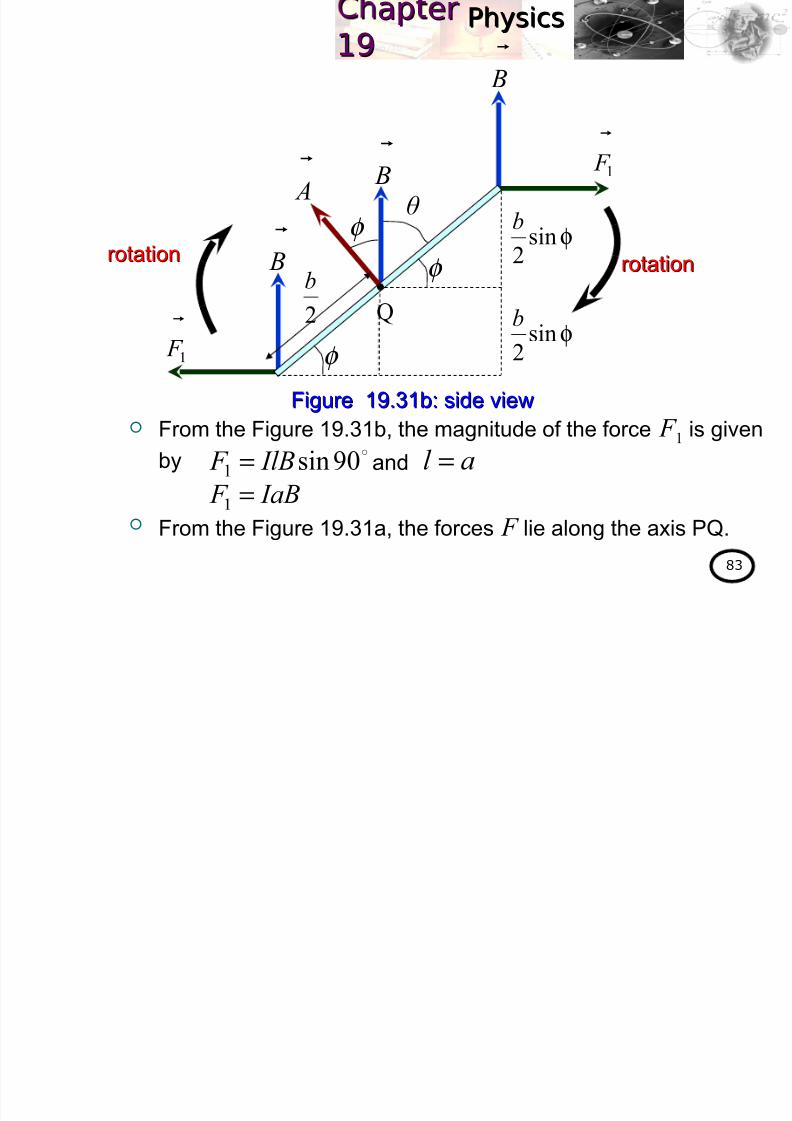
From the Figure 19.31b, the magnitude of the force F 1 is givenby
From the Figure 19.31a, the forces F lie along the axis PQ.
φsin2
b
φsin2
b
θ B
B
B
1 F
1 F
A
φ
Q
φ
φ
2b
rotationrotationrotationrotation
Figure 19.31b: side viewFigure 19.31b: side view
90sin1 IlB F = al =and
IaB F =1
PhysicsPhysicsap erap er1919

8/2/2019 4 Magnetic Field
http://slidepdf.com/reader/full/4-magnetic-field 84/102
84
From the Figure 19.31a, the forces F lie along the axis PQ.
The resultant forceresultant force on the coil is zerozero but the nett torquenett torque is notnot
zerozero because the forces F 1 are perpendicular to the axis PQ asshown in Figure 19.31a.
The forces F 1 cause the coil to rotatecoil to rotate in the clockwise directionclockwise direction
about the axis PQabout the axis PQ as shown in Figure 19.31b.
The magnitude of the nett torque about the axis PQ (refer toFigure 19.31b) is given by
−
−= φ φ sin
2sin
211
b F
b F τ
IaB F =1
−=φ sin
22
1
b F and
( )
−= φ sin
22
b IaB
φ sin IabB−= coil)of area( Aab =and
PhysicsPhysicsap erap er1919

8/2/2019 4 Magnetic Field
http://slidepdf.com/reader/full/4-magnetic-field 85/102
85
since thus
For a coil of N turns, the magnitude of the torque is given by
φ sin IABτ =θ −=φ 90
( )θ IAB −=τ
90sin
θ IABcos=τ
φ sin NIABτ =OR
θ NIABτ cos=
(19.14)(19.14)
(19.15)(19.15)
where coilon thetorque:τ densityfluxmagnetic: Bcoilin theflowscurrent: I
B A
andareactor between veangle:φ Bθ
andcoiltheof planee between thangle:
(coils)turnsof number : N
PhysicsPhysicsap erap er1919

8/2/2019 4 Magnetic Field
http://slidepdf.com/reader/full/4-magnetic-field 86/102
86
From the eq. (19.14), thus the formula of torque in the vector
form is given by
The torque is zerotorque is zero when θ θ = 90= 90°° or or φφ = 0= 0°°and is maximummaximum
when θ θ = 0= 0°° or or φφ = 90= 90°°as shown in Figures 19.32a and
19.32b.
( ) B A NI τ
×= (19.16)(19.16)
0=φ
90=θ B
A
0sin NIABτ =
90cos NIABτ =OR
0=τ
Figure 19.32aFigure 19.32a
B
A
0=θ
90=φ
Figure 19.32bFigure 19.32b90sin NIABτ =
0cos NIABτ =OR
NIABτ =max
plane of the coil
PhysicsPhysicsap erap er1919

8/2/2019 4 Magnetic Field
http://slidepdf.com/reader/full/4-magnetic-field 87/102
87
In a radial fieldradial field, the plane of the coilplane of the coil is always parallelalways parallel to the
magnetic fieldmagnetic field for any orientation of the coil about the vertical
axis as shown in Figure 19.33.
Hence the torquetorque on the coil in a radial fieldradial field is always constantconstantand maximummaximum given by
Radial field is used in moving coil galvanometer.
0=θ
90=φ ORSSNN
coilfixed soft
iron cylinder
radial field
Figure 19.33: Plan view of moving coil meter Figure 19.33: Plan view of moving coil meter
90sin NIABτ = 0cos NIABτ =OR
NIABτ = maximummaximum
PhysicsPhysicsap erap er1919

8/2/2019 4 Magnetic Field
http://slidepdf.com/reader/full/4-magnetic-field 88/102
88
A 50 turns rectangular coil with sides 10 cm × 20 cm is placed
vertically in a uniform horizontal magnetic field of magnitude 2.5 T.
If the current flows in the coil is 7.3 A, determine the torque actingon the coil when the plane of the coil is
a. perpendicular to the field,
b. parallel to the field,
c. at 75° to the field.Solution :Solution :
The area of the coil is given by
a.
Example 19.13 :
A7.3T;5.2turns;50 === I B N
( )( ) 2222 m100.210201010 −−− ×=××= A
From the figure, θ = 90°and φ = 0° , thusthe torque on the coil is
φ sin NIABτ =θ NIABτ cos= OR
B
A
90=θ
90cos NIAB=
0sin NIAB=
0=τ
PhysicsPhysicsap erap er1919

8/2/2019 4 Magnetic Field
http://slidepdf.com/reader/full/4-magnetic-field 89/102
89
Solution :Solution :
b.
c.
B
A
90=φ
From the figure, θ = 0°and φ = 90° ,
thus the torque on the coil isθ NIABτ cos=
( ) ( ) ( )( ) 0cos5.2100.23.750 2−×=m N3.18=τ
A7.3T;5.2turns;50 === I B N
B
A
15=φ
75=θ
From the figure, θ = 75°and φ =15°,thus the torque on the coil is
θ NIABτ cos=
( ) ( ) ( )( )
75cos5.2100.23.750
2−
×= m N72.4=τ
PhysicsPhysicsap erap er1919

8/2/2019 4 Magnetic Field
http://slidepdf.com/reader/full/4-magnetic-field 90/102
90
A galvanometer consists of a coil of wire suspended in the
magnetic field of a permanent magnet. The coil is rectangular
shape and consists of many turns of fine wire as shown in
Figure 19.34.
19.6.2 Moving-coil galvanometer
Figure 19.34Figure 19.34
PhysicsPhysicsap erap er1919
8/2/2019 4 Magnetic Field
http://slidepdf.com/reader/full/4-magnetic-field 91/102
91
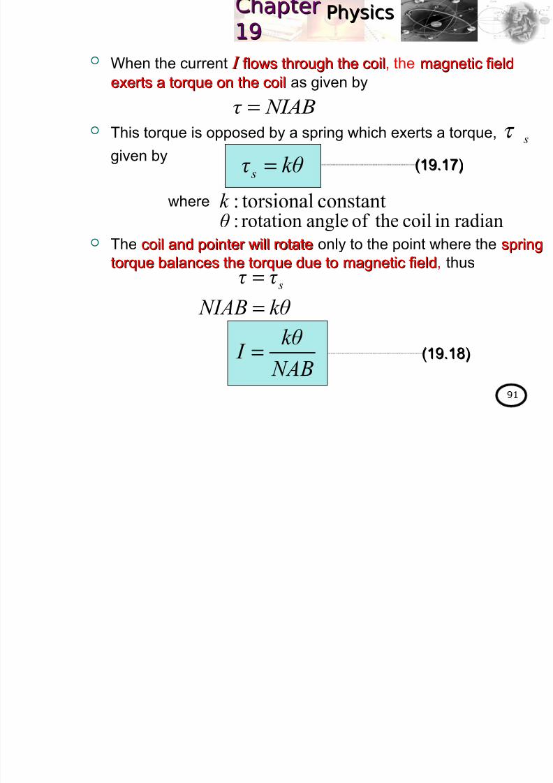
When the current I I flows through the coilflows through the coil, the magnetic fieldmagnetic field
exerts a torque on the coilexerts a torque on the coil as given by
This torque is opposed by a spring which exerts a torque, τ s given by
The coil and pointer will rotatecoil and pointer will rotate only to the point where the springspring
torque balances the torque due to magnetic fieldtorque balances the torque due to magnetic field, thus
NIABτ =
kθ τ s =
where constanttorsional:k radianincoiltheof anglerotation:θ
sτ τ =kθ NIAB =
NAB
kθ I =
(19.17)(19.17)
(19.18)(19.18)
PhysicsPhysicsap erap er1919

8/2/2019 4 Magnetic Field
http://slidepdf.com/reader/full/4-magnetic-field 92/102
92
A rectangular coil of 10 cm × 4.0 cm in a galvanometer has 50
turns and a magnetic flux density of 5.0 × 10⁻² T. The resistance of
the coil is 40 Ω and a potential difference of 12 V is applied acrossthe galvanometer, calculate the maximum torque on the coil.
Solution :Solution :
The area of the coil is given by
The current through the galvanometer is
Therefore the maximum torque on the coil is
Example 19.14 :
( )( ) 2322 m100.4100.41010 −−− ×=××= A
( )4012 I = IRV =
A3.0= I
NIAB=maxτ
m N100.33
max
−
×=τ
;04T;100.5turns;502 Ω=×== −
R B N V12=V
( ) ( ) ( )( )23100.5100.43.050
−− ××=
PhysicsPhysicsap erap er1919

8/2/2019 4 Magnetic Field
http://slidepdf.com/reader/full/4-magnetic-field 93/102
93
Exercise 19.5 :1. A moving coil meter has a 50 turns coil measuring 1.0 cm by
2.0 cm. It is held in a radial magnetic field of flux density
0.15 T and its suspension has a torsional constant of 3.0× 10⁻⁶ N m rad−1. Determine the current is required to give a
deflection of 0.5 rad.
ANS. :ANS. : 1.01.0×× 1010−−33 AA
PhysicsPhysicsap erap er1919

8/2/2019 4 Magnetic Field
http://slidepdf.com/reader/full/4-magnetic-field 94/102
94
At the end of this chapter, students should be able to:At the end of this chapter, students should be able to:
ExplainExplain the motion of a charged particle in boththe motion of a charged particle in both
magnetic field and electric field.magnetic field and electric field.
Derive and useDerive and use velocity,velocity,
in a velocity selector.in a velocity selector.
Learning Outcome:
19.7 Motion of charged particle in magnetic field
and electric field (1 hour)
B
E v =
w w w
.k m p
h . m
a t r
i k . e
d u
. m y
w w w
.k m p
h . m
a t r
i k . e
d u
. m y
PhysicsPhysicsap erap er1919
8/2/2019 4 Magnetic Field
http://slidepdf.com/reader/full/4-magnetic-field 95/102
95
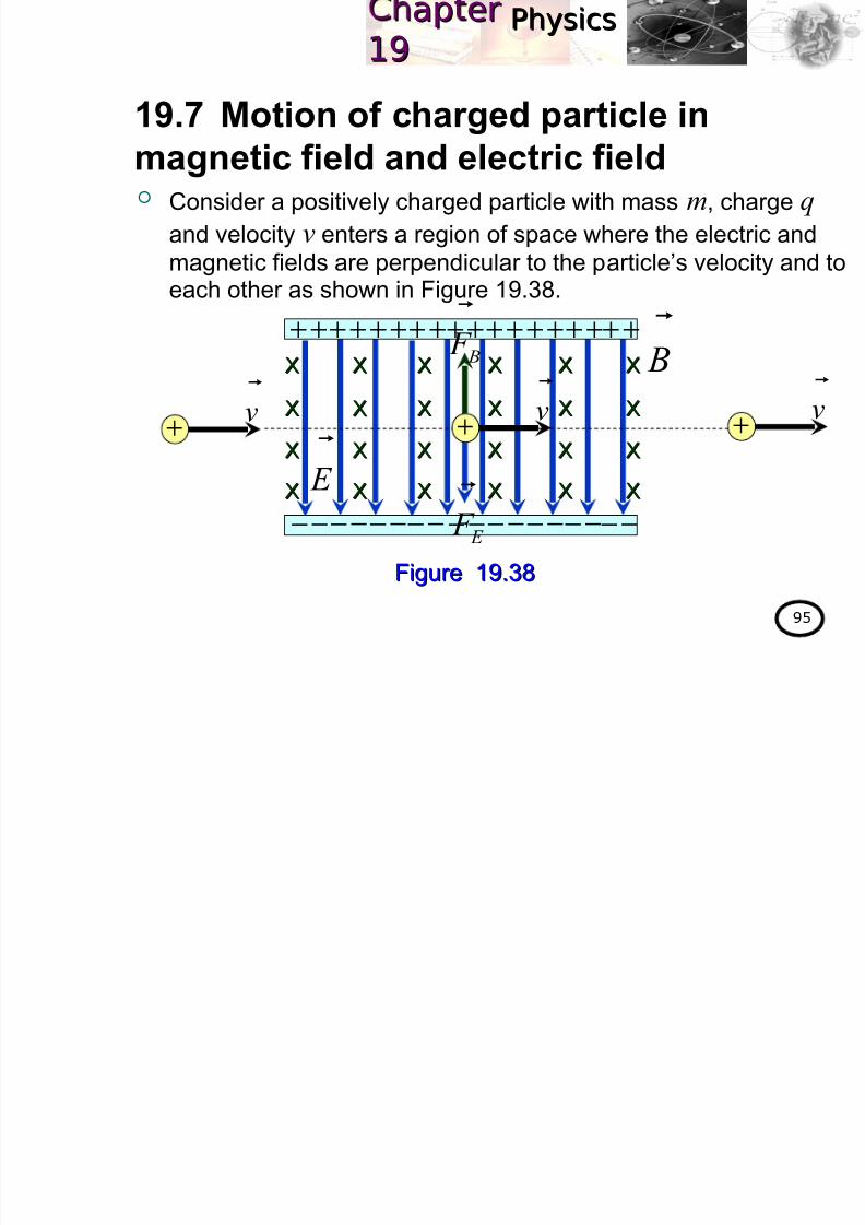
Consider a positively charged particle with mass m, charge q
and velocity v enters a region of space where the electric and
magnetic fields are perpendicular to the particle’s velocity and toeach other as shown in Figure 19.38.
19.7 Motion of charged particle in
magnetic field and electric field
Figure 19.38Figure 19.38
E
++++++++++++++++++
−−−−−−−−−−−−−−−−−−
XX XX XX XX XX XX
XX XX XX XX XX XX
XX XX XX XX XX XX
XX XX XX XX XX XX
B
v
+ v
+ v
+
B F
E F
PhysicsPhysicsap erap er1919

8/2/2019 4 Magnetic Field
http://slidepdf.com/reader/full/4-magnetic-field 96/102
96
The charged particle will experiences the electric force F E is
downwards with magnitude qE and the magnetic force F B is
upwards with magnitude qvB as shown in Figure 19.38.
If the particle travels in a straight line with a constant velocity
hence the electric and magnetic forces are equal in magnitudeelectric and magnetic forces are equal in magnitude.
Therefore
Only the particles with velocity equal tovelocity equal to E/B E/B can pass throughcan pass through
without being deflected by the fieldswithout being deflected by the fields.
Eq. (19.21) also works for electron or other negatively charged
particles.
E B F F =qE qvB =90sin
B
E v = (19.21)(19.21)
PhysicsPhysicsap erap er1919

8/2/2019 4 Magnetic Field
http://slidepdf.com/reader/full/4-magnetic-field 97/102
97
Figure 19.38 known as velocity selector velocity selector .
Normally, after the charged particle passing through the velocityselector it will enter the next region consist of a uniformuniform
magnetic field onlymagnetic field only. This apparatus known as massmass
spectrometer spectrometer as shown in Figure 19.39.
Figure 19.39Figure 19.39
E
++++++++++++++++++
−−−−−−−−−−−−−−−−−−
XX XX XX XX XX XX
XX XX XX XX XX XX
XX XX XX XX XX XX
XX XX XX XX XX XX
B
v
+
E F
XX XX XX XX XX
XX XX XX XX XX
XX XX XX XX XX
XX XX XX XX XX
XX XX XX XX XX
XX XX XX XX XX
XX XX XX XX XX
XX XX XX XX XX
XX XX XX XX XX
v
+
XX XX XX XX XX
B F
v
B F
r
+
v
+
PhysicsPhysicsap erap er1919

8/2/2019 4 Magnetic Field
http://slidepdf.com/reader/full/4-magnetic-field 98/102
98
When the charged particle entering the region consist of charged particle entering the region consist of
magnetic field onlymagnetic field only, the particle will make a semicircular pathparticle will make a semicircular path of
radius r as shown in Figure 19.39.Therefore
From the eq. (19.22), the mass spectrometer can be used to
determine the value of determine the value of q/ q/ mm for any charged particle.
C B F F =
rB
v
m
q
= and
r
mvqvB
2
=
B
E v =
2rB
E
m
q= (19.22)(19.22)
PhysicsPhysicsap erap er1919
8/2/2019 4 Magnetic Field
http://slidepdf.com/reader/full/4-magnetic-field 99/102
99
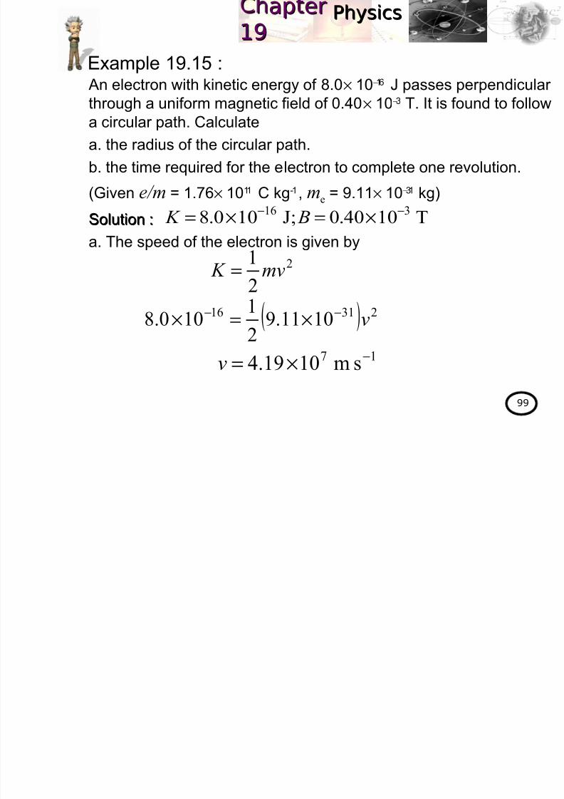
An electron with kinetic energy of 8.0× 10⁻¹⁶ J passes perpendicular
through a uniform magnetic field of 0.40× 10⁻³
T. It is found to followa circular path. Calculate
a. the radius of the circular path.
b. the time required for the electron to complete one revolution.
(Given e/m = 1.76× 10¹¹ C kg-1, me = 9.11× 10⁻³¹ kg)
Solution :Solution :
a. The speed of the electron is given by
Example 19.15 :
T1040.0J;100.8 316 −− ×=×= B K
2
2
1mv K =
( ) 23116 1011.921100.8 v−− ×=×
17 sm1019.4 −×=v
PhysicsPhysicsap erap er1919
316

8/2/2019 4 Magnetic Field
http://slidepdf.com/reader/full/4-magnetic-field 100/102
100
Solution :Solution :
a. Since the path made by the electron is circular, thus
b. The time required for the electron to complete one revolution is
given by
T1040.0J;100.8316 −− ×=×= B K
C BF F
=r
mvevB
2
90sin =
r
v B
m
e=
( )( ) r
7
311 1019.41040.01076.1 ×=×× −
m595.0=r
T
πr
v
2
=( )T
π 595.021019.4 7 =×
s1092.8 8−×=T
PhysicsPhysicsap erap er1919
E i 19 6

8/2/2019 4 Magnetic Field
http://slidepdf.com/reader/full/4-magnetic-field 101/102
101
Exercise 19.6 :1. An electron moving at a steady speed of 0.50× 10⁶ m s−1
passes between two flat, parallel metal plates 2.0 cm apart
with a potential difference of 100 V between them. Theelectron is kept travelling in a straight line perpendicular to the
electric field between the plates by applying a magnetic field
perpendicular to the electron’s path and to the electric field.
Calculate :
a. the intensity of the electric field.
b. the magnetic flux density needed.
ANS. :ANS. : 0.500.50×× 101044 V mV m−−11; 0.010 T; 0.010 T
2. A proton moving in a circular path perpendicular to a constant
magnetic field takes 1.00 µ s to complete one revolution.
Determine the magnitude of the magnetic field.
(Physics for scientist and engineers, 6(Physics for scientist and engineers, 6thth edition, Serway&Jewet, Q32,edition, Serway&Jewet, Q32,
p.921)p.921)
(m p=1.67× 10⁻²⁷ kg and charge of the proton, q=1.60× 10⁻¹⁹ C)
ANS. :ANS. : 6.566.56×× 1010−−22 TT
PhysicsPhysicsap erap er1919
8/2/2019 4 Magnetic Field
http://slidepdf.com/reader/full/4-magnetic-field 102/102
Next Chapter…CHAPTER 20 :
Electromagnetic induction
w w w
.k m p
h . m
a t r
i k . e
d u
. m y
w w w
.k m p
h . m
a t ri
k . e
d u
. m y