4. nia 1 j. v. - digital library/67531/metadc715589/m2/1/high_res_d/782433.pdfsnf-4207 rev 0...
TRANSCRIPT
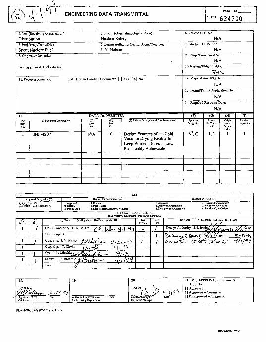
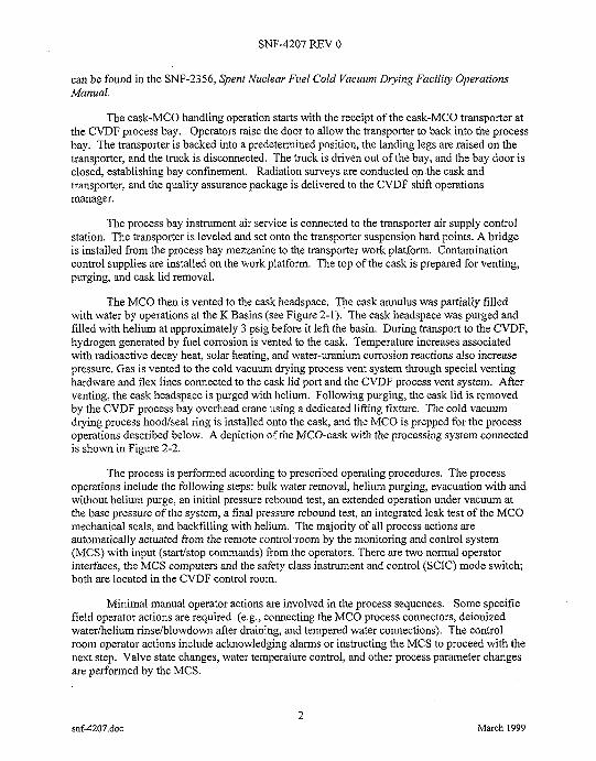
Page 1 of 'q ' ENGINEERING D A T A TRANSMITTAL 624300
2. TO (Receiving Organization) 3. From: (Originating Organization) Distribution Nuclear Safety
4. Related EDTNo.: NIA
Spent Nuclear Fuel 1 J. V. Nelson NIA
. , Ifem NO.
8. Originator Remarks:
1
9. Equip./Component No.: NIA
I 18 I 19.
For approval and release.
11. Receiver Remarks 11A Design &ueline Document? [ ] Yes [XI No
20. 21. DOE APPROVAL(ifrequired) Ctrl. No.
1 1 Approved I / 4 7 [ 1 Approved w/comments
[ ] Disapproved w/comments -
IO. SystedBldg.lFacililytr:
w-441
NIA
NIA
NIA
12. Major Assm Dwg. No.:
13. Pmitmermit ApplicationNo.:
14. Required Response Date:
BD-7400-172-2 (OY96) GEF097
BO-74001 72-1

SNF-4207. Rev. 0
Design Features of the Cold Vacuum Drying Facility to Keep Worker Doses as Low as Reasonably Achievable
3
J. V. Nelson DE&S Hanford, Richland, WA 99352 U.S. Department of Energy Contract DE-AC06-96RL13200
EDT: 624300 UC: 920 Org Code: 2F200 B&R Code: EW3 1354040
Key Words: Cold Vacuum Drying Facility, CVDF, ALARA, Radiation Protection, Occupational
Abstract: This report describes the design features and steps taken to ensure that the Cold Vacuum Drying Facility satisfies regulatory requirements that personnel doses be kept as low as reasonably achievable (ALARA). This report also documents an analysis of worker doses and demonstrates that the ALARA goal of limiting individual doses to 500 mrem per year can be met.
C h g e Code: 105568/CB80 TotalPages: 57
Radiation Exposure, Radiological Dose
TRADEMARK DISCLAJUER. Refncnce herein to any specific mmere id pcduet. process or m c e by trade nunc, trademark manufamrcr, or otherwise. does not ncccsurily COnstiNte or smply ils rndonemnS rccomntendalion. or favoring by thc UMed States Govrmmnt or any agmcy thereof or i l l conmaon or subcontracton
Printed in the United Stater of Ammica To obtain copies ofthis document, contact: Dowment Contml Services, P.O. Box 950, Mailstop H668, Richland WA99352, Phone (509) 372-2420; Fax (509) 37
Rel&dAAp6roval Date Release Sfamp
Approved for Public Release A-6400-073 (01/97) GEF321
SNF-4207 REV 0
snf-4207.doc
DESIGN FEATURES OF THE COLD VACUUM DRYING FACILITY TO KEEP WORKER DOSES AS LOW
AS REASONABLY ACHIEVABLE
March 1999
1 March I999
SNF-4207 REV 0
CONTENTS
1 .O INTRODUCTION .................................................................................................................. 1 1.1 PURPOSE ................. 1 1.2 SCOPE ............................................................................................................................ 1
2 .O OVERVIEW OF THE COLD VACUUM DRYING FACILITY AND OPERATIONS ...... 1 3 .O REGULATORY AND PROCEDURAL REQUIREMENTS ................................................ 5 4 .O DESIGN AND ANALYSIS INPUTS .................... 6 5 .O ASSUMPTIONS ..................................................................................................................... 7 6 .O SOURCE TERM .............................................. 7 7 .O RADIOLOGICAL DESIGN REVIEW PROCESS ................................................................ 9 8 .O FINAL ALARA DESIGN FEATURES INCORPORATED ............................................... 10
8.1 PROCESS DESIGN ............................................................ 8.2 EQUIPMENT RELIABILITY ASSESSMENT AND MAINTENANCE ................... 13 8.3 DECOMMISSIONING ................................. 8.4 INSTALLATION ..........................................
9 .O ASSESSMENT OF PERSONNEL DOSES 9.1 NORMAL OPERATIONS ................... 9.2 EQUIPMENT MAINTENANCE AND CALIBRATION 9.3 ROUTINE PATROL, SURVEILLANCE, HOUSEKEEP
CONTAMINATION CONTROL 10 .O CONCLUSION .............................. 11 .O REFERENCES ..............................
ATTACHMENT A COLD VACUUM DRYING FAC RADIATION DOSE ASSESSME
snf-4207.doc 11
March 1999

SNF-4207 REV 0
LIST OF FIGURES
Figure 2-1 Cask-Multi-Canister Overpack Configuration upon Receipt at the Cold Vacuum Drying Facility. ................................................................................... 3
Figure 2-2 Cask-Multi-Canister Overpack Configuration with Process Systems at the Cold Vacuum Drying Facility. ............................................................................. 4
LIST OF TABLES
Table 6-1
Table 6-2
Table 8-1
Table 9-1
Table 9-2
Radionuclide Concentrations in Source Material ........................................................ 8
Source Material Concentration in each Process Water Conditioning Component
Radiation Monitors in the Cold Vacuum Drying Facility. ........................................ 12
General Locations and Dose Rates in the Cold Vacuum Drying Facility. ................ 16
Cold Vacuum Drying Facili Overpack Processed ........... ................................. 17
and Repair Operations. ................................... Table 9-3 Cold Vacuum Drying Facility Personnel Exposure During Maintenance
..... 18
Table 9-4 Cold Vacuum Drying Facility Personnel Exposure during Routine Patrol, Surveillance, Housekeeping, and Contamination Control. ... 19
snf-4207.doc
... 111
March 1999

SNF-4207 REV 0
ALAFL4 CSB CVDF DOE IXM MCO MCS NRC PWC SCIC SNF
snf-4207.doc
LIST OF TERMS
as low as reasonably achievable Canister Storage Building Cold Vacuum Drying Facility U S . Department of Energy ion exchange module multi-canister overpack monitoring and control system U S . Nuclear Regulatory Commission process water conditioning safety class instrumentation and control spent nuclear fuel
iv March 1999
SNF-4207 REV 0
1.0 INTRODUCTION
The goal of the Spent Nuclear Fuel (SNF) Project is to remove all SNF from the K Basins in the Hanford lOOK Area and put it in interim dry storage at the Canister Storage Building (CSB) in the 200 East Area. Removal of SNF from the K Basins entails loading the intact fuel canisters and fuel scrap into specially designed baskets, which are stacked in water-filled multi- canister overpacks (MCOs). The mission of the Cold Vacuum Drying Facility (CVDF), also located in the lOOK Area, is to remove and process the free water in the loaded MCOs before they are transported to the CSB. Removal of the water from the MCOs is necessary to prevent water-induced corrosion of exposed fuel surfaces and to allow the loaded MCOs to be safely transported to and stored in the CSB.
1.1 PURPOSE
The purpose of this report is to outline the steps taken to ensure that the CVDF meets the regulatory requirements that dose rates be maintained as low as reasonably achievable (ALARA). This report documents the regulatory requirements, design and analysis inputs, applicable assumptions, radiological source terms, expected worker doses, and the design review process used. The report also documents the optimization that has resulted in ALARA design features implemented for normal processing, maintenance, and the eventual decommissioning of the facility.
1.2 SCOPE
This report considers only the engineering design features and controls used to keep personnel dose rates ALARA. Standard administrative controls for ALARA, such as training, radiation monitoring, posting, labeling, access control, job planning, and records keeping and reporting are also implemented at the CVDF, but engineering controls are the primary means of providing radiation protection.
This report considers radiation protection to CVDF personnel only. Doses from normal CVDF operations to Hanford Site workers outside the CVDF and to the general public are insignificant, and potential dose rates under accident scenarios are covered in the CVDF Safety Analysis Report.
2.0 OVERVIEW OF THE COLD VACUUM DRYING FACILITY AND OPERATIONS
This section provides a brief overview of the CVDF and the routine operations conducted there to receive, drain, and prepare an MCO for transport to the CSB and to process water extracted from the MCO before it is shipped back to the K Basins. Details of these operations
snf-4207.doc 1
March 1999
SNF-4207 REV 0
can be found in the SNF-2356, Spent Nuclear Fuel Cold Vacuum Drying Facility Operations Manual.
The cask-MCO handling operation starts with the receipt of the cask-MCO transporter at the CVDF process bay. Operators raise the door to allow the transporter to back into the process bay. The transporter is backed into a predetermined position, the landing legs are raised on the transporter, and the truck is disconnected. The truck is driven out of the bay, and the bay door is closed, establishing bay confinement. Radiation surveys are conducted on the cask and transporter, and the quality assurance package is delivered to the CVDF shift operations manager.
The process bay instrument air service is connected to the transporter air supply control station. The transporter is leveled and set onto the transporter suspension hard points. A bridge is installed from the process bay mezzanine to the transporter work platform. Contamination control supplies are installed on the work platform. The top of the cask is prepared for venting, purging, and cask lid removal.
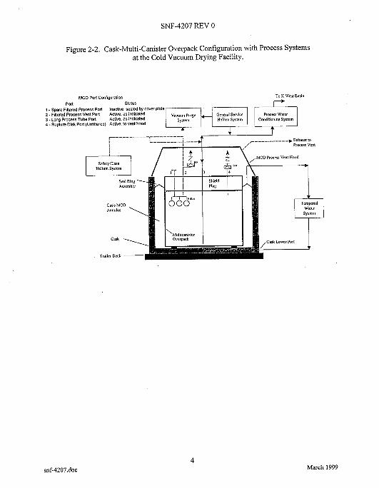
The MCO then is vented to the cask headspace. The cask annulus was partially filled with water by operations at the K Basins (see Figure 2-1). The cask headspace was purged and filled with helium at approximately 3 psig before it left the basin. During transport to the CVDF, hydrogen generated by fuel corrosion is vented to the cask. Temperature increases associated with radioactive decay heat, solar heating, and water-uranium corrosion reactions also increase pressure. Gas is vented to the cold vacuum drying process vent system through special venting hardware and flex lines connected to the cask lid port and the CVDF process vent system. After venting, the cask headspace is purged with helium. Following purging, the cask lid is removed by the CVDF process bay overhead crane using a dedicated lifting fixture. The cold vacuum drying process hoodkeal ring is installed onto the cask, and the MCO is prepped for the process operations described below. A depiction of the MCO-cask with the processing system connected is shown in Figure 2-2.
The process is performed according to prescribed operating procedures. The process operations include the following steps: bulk water removal, helium purging, evacuation with and without helium purge, an initial pressure rebound test, an extended operation under vacuum at the base pressure of the system, a final pressure rebound test, an integrated leak test of the MCO mechanical seals, and backfilling with helium. The majority of all process actions are automatically actuated from the remote control room by the monitoring and control system (MCS) with input ( s t d s t o p commands) from the operators. There are two normal operator interfaces, the MCS computers and the safety class instrument and control (SCIC) mode switch; both are located in the CVDF control room.
Minimal manual operator actions are involved in the process sequences. Some specific field operator actions are required (e.g., connecting the MCO process connectors, deionized waterhelium rinseiblowdown after draining, and tempered water connections). The control room operator actions include acknowledging alarms or instructing the MCS to proceed with the next step. Valve state changes, water temperature control, and other process parameter changes are performed by the MCS.
snf-4207.doc 2
March 1999

SNF-4207 REV 0
Figure 2-1. Cask-Multi-Canister Overpack Configuration upon Receipt at the Cold Vacuum Drying Facility.
Vent Pon (blanked Purge Pon (blanked by Quick /by Seal Cover) - Disconnect a Seal Cover) T
Cask Drain Pwt (blank4 by Quih Di-d 8 Seal Cwer
snf-4207.doc 3
March 1999
SNF-4207 REV 0
Figure 2-2. Cask-Multi-Canister Overpack Configuration with Process Systems at the Cold Vacuum Drying Facility.
MCO Port Configuration To K Wen Basin
DArt SIatuS r' ,
vacuum Purge General Scrvice Proces water I -Spare Filtered Process POlt Inanive, sealed by Cover plate 2. ~lltered Process Vent Polt 3. Long P ~ O C ~ S S Tube Port
Aaae. as indicated Aaive. as indicated
4 - Rupture Disk Port (Unfiltered) Anive, 10 Yen1 h w d
Cask Annl
-MCO llyI
Ring 1 mbly
\
Tadcr cask Deck 3 -
snf-4207.doc 4
March 1999

SNF-4207 REV 0
Protection from off-site consequences is provided by maintaining water in the cask-MCO annulus space, pressure venting using a 30-psig rupture disc, and automatically actuating the SCIC system. The 30-psig vent path is passive, and the system maintaining annulus water is, for the most part, passive. The SCIC will prevent the tempered water temperatures from exceeding 50 “C by stopping the tempered water heater and circulation pump upon detection of high temperatures.
The contaminated MCO water that was pumped to the receiver tanks into the process water conditioning (PWC) room is processed through an ion-exchange module (IXM) until the water is purified sufficiently to be returned to the K Basins. The water is then processed through a mechanical finishing filter (referred to as the PWC filter) and into a large (5,000-gal) storage tank. The water then is loaded into tanker trucks and shipped back to the K Basins.
Following the cold vacuum drying process, the cask-MCO transporter is prepped for shipment to the CSB. This operation is the reverse of the receipt operation. The cask-MCO is brought to a temperature of 25 “C. The MCO is pressurized with helium to 11 k 0.5 psig and is then closed. Next, the cask annulus is drained and dried with an instrument air purge, a helium leak test of the MCO is performed, and the cask lid is reinstalled. Only 1 atm of air is left in the cask annulus. Finally, the transporter is connected to the truck and released for shipment to the CSB.
In addition to the operations described above to process an MCO, there are other ongoing activities at the CVDF. These activities, which are discussed in Sections 9.2 and 9.3, include periodic equipment maintenance and calibration and daily patrols, surveillances, housekeeping, and contamination control.
3.0 REGULATORY AND PROCEDURAL REQUIREMENTS
DOE N5480.6, DOE Radiological Control Manual, and HSRCM-1, Hanford Site Radiological Control Manual, require that equipment and procedures be designed to ensure that worker whole body exposure remains below the ALARA design goal of 500 mredyear. The federal law governing radiation exposure for this type of work is provided in Title 10, Code of Federal Regulations, Part 835, “Occupational Radiation Protection” (10 CFR 835). This code establishes radiation protection standards for the conduct of U.S. Department of Energy (DOE) activities. The annual limit for total effective dose equivalent is 5 rem. An administrative limit of 1.0 rem for whole body dose is set by 10 CFR 835 for occupational workers. Compliance with this limit is assured when the 500-mrem ALARA design goal is achieved. Section 10.0 demonstrates how these ALARA design goals have been met.
Radiological protection standards at the CVDF are required to achieve US. Nuclear Regulatory Commission (NRC) equivalency (HNF-SD-SNF-DB-003 and HNF-SD-SNF-SP-012). Other NRC requirements pertaining to radiation protection are delineated in 10 CFR 72, “Licensing Requirements for the Independent Storage of Spent Nuclear Fuel and High-Level Radioactive Waste.” The NRC requirements in 10 CFR 72 are similar to
snf-4207.doc 5
March I999

SNF-4207 REV 0
the requirements delineated in DOE orders (e.g., DOE Order 5480.23, Nuclear Safety Analysis Reports).
Both HNF-SD-SNF-DB-003, Spent Nuclear Fuel Project Path Forward, Additional NRC Requirements, and HNF-SD-SNF-SP-012, Additional Guidance for Including Nuclear Safety Equivalency in the Canister Storage Building and the Cold Vacuum Drying Facility Final Safety Analysis Reports, require that the CVDF have devices that restrict access to all high-radiation areas, and that the installation of those devices conform to Section 20.1601 of 10 CFR 20, “Standards for Protection against Radiation.” High-radiation areas are defined in Section 20.1003 of 10 CFR 20 to be 0.1 rem in 1 h a t 30 cm. This is more restrictive than 10 CFR 835, where entry control devices are not required until doses in accessible areas reach 1 rem in 1 h at 30 cm. HNF-SD-SNF-DB-003 also requires that the CVDF incorporate applicable requirements of NRC Regulatory Guide 8.8, Information Relevant to Ensuring that Occupational Radiation Exposures at Nuclear Power Stations will be as Low as Reasonably Achievable. The applications of the requirements for engineered controls in NRC Regulatory Guide 8.8 to the CVDF design are described in Section 8.1.
4.0 DESIGN AND ANALYSIS INPUTS
A block flow diagram for the cold vacuum drying process was developed during the conceptual design phase and revised during the definitive design phase. Throughout the CVDF design phase, process durations were extracted from the block flow diagrams and dose constraints were established based on the expected dose at each facility location. The current flow diagram, which is documented in SNF-2356, identifies each step in the cold vacuum drying process and provides an estimate of the time required for each step. The time estimates, along with dose rate maps for a typical process bay and the PWC room, were used as a basis for calculating personnel radiation exposure. The dose rate maps, which are documented in HNF-2850, Shielding Analysis for the Cold Vacuum Drying Project, were produced for various elevations in a processing bay and in the PWC room.
The dose rates used in constructing the maps were computed using the computer programs ISO-PC 1.98 (WHC-SD-WM-UM-030) and MCNPH (WHC-SD-MP-SWD-30001). ISO-PC 1.98 is a point-kernel program based on ISOSHLD (BNWL-236 SUPl). MCNPH is the Hanford version of the Monte Carlo program MCNP 4A (Breismeister 1993), which was developed and is maintained at Los Alamos National Laboratory. Both the MCNP 4A and ISOSHLD programs are widely used, well tested, and proven to give reliable results.
By combining the dose rate contour maps with information from the process diagram and estimates of manpower required to maintain and calibrate equipment and complete routine patrol, surveillance, housekeeping, and contamination control activities, a model of the CVDF was developed to determine the personnel exposure to radiation that could be expected during operation of the facility. That analysis, “Cold Vacuum Drying Facility Worker Radiation Dose Assessment,” is included as Attachment A to this report. Each activity at the CVDF was evaluated to determine the integrated radiation exposure of the personnel performing the activity.
snf-4207.doc 6
March 1999

SNF-4207 REV 0
By using this model, the activities that produced the highest personnel exposure were identified and investigated for possible exposure reduction as part of the ALARA review process. After accounting for the final ALARA design features described in Section 8.0, a final assessment of integrated personnel was made. The results of that assessment are presented in Section 9.0.
5.0 ASSUMPTIONS
The radiation sources used in the shielding calculations are defined in Section 6.0. Personnel activities and their assumed duration were based on information given in SNF-2356. The duration of each operational activity was assumed to be as given in Attachment A. It was also assumed that the basin water drained from the MCO was processed through an IXM and a PWC filter in the PWC room. To reduce the exposure of personnel in the room, the six ion- exchange columns in each IXM are housed in steel canisters and shielded by concrete, while the filter is encased in steel 1.5 in. thick.
Assumptions about the frequency o f maintenance activities, calibration activities, and the IXM and filter changeouts are given in Section 9.2.
6.0 SOURCE TERM
Potential radiation sources associated with the cold vacuum drying process are:
The SNF and contaminated water inside the MCO
Dissolved fission products and fuel particulate contained in the water extracted from each MCO
Radioactive particulate associated with gases that are purged or evacuated from the MCO.
The radioactive particulate that could be carried by gases is confined inside the shielded MCO by the metal high-efficiency particulate air filter in the MCO and, thus, is assumed to constitute an insignificant radiation source compared to the SNF and contaminated MCO water.
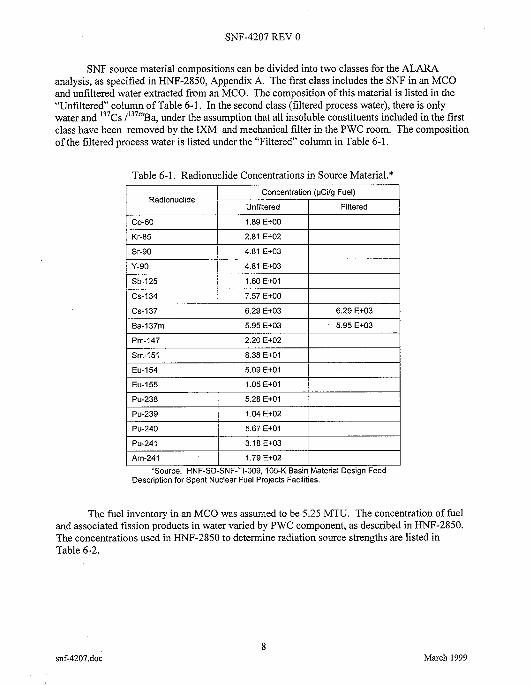
Conversion of fuel mass (grams) to radionuclide activity (curies) was done using the average fuel curies per metric tonne uranium (Ci/MTU) data tabulated in HNF-SD-SNF-TI-009, 105-K Basin Material Design Basis Feed Description for Spent Nuclear Fuel Project Facilities. Table 6-1 lists the significant radionuclides and their activity levels. The activity units in Table 6-1 are microcuries per gram (pCi/g) of fuel plus fission products, which are equivalent to the units of Ci/MTU reported in HNF-SD-SNF-TI-009.
snf-4207.doc 7
March 1999
SNF-4207 REV 0
Unfiltered
SNF source material compositions can be divided into two classes for the ALARA analysis, as specified in HNF-2850, Appendix A. The first class includes the SNF in an MCO and unfiltered water extracted from an MCO. The composition of this material is listed in the “Unfiltered” column of Table 6-1. In the second class (filtered process water), there is only water and I3’Cs /‘37mBa, under the assumption that all insoluble constituents included in the first class have been removed by the IXM and mechanical filter in the PWC room. The composition of the filtered process water is listed under the “Filtered” column in Table 6-1.
Filtered
Table 6-1. Radionuclide Concentrations in Source Material.*
03-60
Kr-85
Sr-90
1.89 E+OO
2.81 E+02
4.81 E+03
Cs-137
I Y-90 I 4.81 E+03 I 1
6.29 E+03 6.29 E+03
I Sb-125 I 1.60 E+01 I 1
Eu-154
Eu-155
Pu-238
I Cs-134 I 7.57E+OO I 1
5.09 E+01
1.05 E+01
5.28 E+01
Pu-240
Pu-241
Am-241
I Pm-147 I 2.20 E+02 I 1
5.67 E+01
3.18 E+03
1.79 E+02
I Sm-151 I 8.38 E+01 I 1
I Pu-239 I 1.04E+02 I 1
I I I 1 ’Source: HNF-SD-SNF-TI-009,105-K Basin Material Design Feed
Description for Spent Nuclear Fuel Projects Facilities.
The fuel inventory in an MCO was assumed to be 5.25 MTU. The concentration of fuel and associated fission products in water varied by PWC component, as described in HNF-2850. The concentrations used in HNF-2850 to determine radiation source strengths are listed in Table 6-2.
snf-4207.doc 8
March 1999

SNF-4207 REV 0
Piping
Check valve
Table 6-2. Source Material Concentration in each Process Water Conditionine Comuonent.
1.27 E-04 62.6 g fuel removed with 490 L of process water (unfiltered)
3 a fuel Der valve (1 om3 volume) [unfiltered) 1 3.00 E+OO
I 1 Component Source specification Fuel concentration in I process water (g/cm3)
Receiver tanks 62.6 g fuel suspended in 490 L process water 1.27 E-04
4.06 E-03
(filtered)
(filtered)
Source: HNF-2850, Shielding Analysis for the Cold Vacuum Drying Project.
IXM = ion exchange module. PWC = process water conditioning.
Only photon radiation exposures were computed in HNF-2850. Existing shielding, pipes, and vessel walls effectively attenuate alpha and beta radiation. However, bremsstrahlung was accounted for in the ISO-PC calculations. Neutron dose rates from SNF sources are orders of magnitude less than photon dose rates outside unshielded, water-shielded, or concrete-shielded containers. This was verified by estimating the neutron dose rate for one case using the method given in Estimation ofNeutron Dose Rates from Nuclear Waste Packages (Nelson 1996). In that case, the neutron dose rate 30 cm from a check valve with a 3-g deposit of fuel particulate (an assumed worst case) was computed and compared to the photon dose rate reported in HNF-2850. The result of this comparison was that the neutron dose rate was only 0.04% of the photon dose rate (0.022 versus 52.1 mrem/h). Steel, on the other hand, is much more effective at attenuating photons than neutrons. Thus, the fractional contribution of neutrons to the total dose rate outside the MCO transportation cask will be higher. However, previous analyses (WHC-SD-SNF-CAVR-001 and HNF-SD-SNF-CN-026) determined that neutrons still account for only about 10% of the dose rate outside an MCO cask.
7.0 RADIOLOGICAL DESIGN REVIEW PROCESS
The ALARA requirements and objectives followed during the CVDF design are given below.
1. Optimization principles, as discussed in ICRF' Publication 37, Cost-Bene$t Analysis in the Optimization of Radiation Protection, shall be used in developing and justifying design and physical controls.
snf-4207.doc 9
March 1999
SNF-4207 REV 0
2. External exposure shall not exceed 500 mrem per year (DOE N5480.6 and HSRCM-1).
3. Airborne radioactive particles are to be contained and filtered so that no internal exposure is expected under normal operating conditions.
Ease of maintenance, decontamination, and decommissioning are to be considered in the design and selection of materials.
4.
ICRF' Publication 37 discusses the principles and methods for achieving the optimization required as part of a system dose limitation. The guidance given is that all exposures shall be kept ALARA, with economic and social factors taken into account.
Engineering controls selected for maintaining the internal and external radiation exposure ALARA included the use of confinement, ventilation, remote handling, and shielding. The process was an iterative one that addressed ALARA issues as the design evolved. Thus, ALARA features were integrated during the design process, rather than being identified and incorporated after the completion of the definitive design.
Operations personnel and radiological control personnel were involved in the ongoing design and review process to identify opportunities of dose radiation.
The NRC Regulatory Guide 8.8 provides information for ensuring that occupational radiation exposures at nuclear power stations will be ALARA. Although the CVDF is not a nuclear power plant, much of the information in the guide can be applied; these items were included in CDVF design as required by HNF-SD-SNF-DB-003 and HNF-SD-SNF-SP-012. Every design feature listed in Sections 8.1 and 8.2 complies with one or more recommendations from the NRC Regulatory Guide 8.8. Although this guide does not address decommissioning, the design features listed in Section 8.3 for keeping personnel dose rates ALARA during decommissioning of the CVDF have a basis in the guide.
8.0 FINAL ALARA DESIGN FEATURES INCORPORATED
8.1 PROCESS DESIGN
The areas of high radiation exposure were identified from the block flow diagram and the model of the cold vacuum drying process. Many of the design features were then revised to reduce the amount of expected exposure to the personnel performing the activities. Examples of revised design features are included in this section.
An early CVDF design change to keep personnel doses ALARA involved incorporating shield walls between the bays to reduce exposure from an MCO in an adjacent bay. The concrete walls between the bays reduced the background to 0.1 mrem/h, thereby mitigating the dose rate from an MCO in an adjacent bay.
snf-4207.doc 10
March 1999
SNF-4207 REV 0
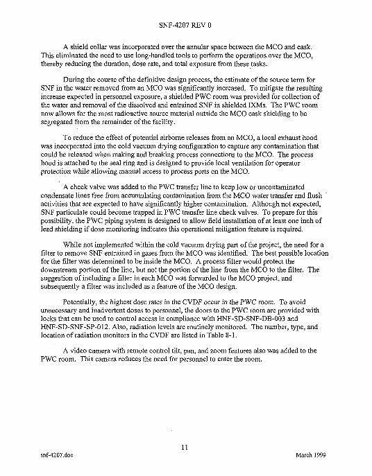
A shield collar was incorporated over the annular space between the MCO and cask. This eliminated the need to use long-handled tools to perform the operations over the MCO, thereby reducing the duration, dose rate, and total exposure from these tasks.
During the course of the definitive design process, the estimate of the source term for SNF in the water removed from an MCO was significantly increased. To mitigate the resulting increase expected in personnel exposure, a shielded PWC room was provided for collection of the water and removal of the dissolved and entrained SNF in shielded IXMs. The PWC room now allows for the most radioactive source material outside the MCO cask shielding to be segregated from the remainder of the facility.
To reduce the effect of potential airborne releases from an MCO, a local exhaust hood was incorporated into the cold vacuum drying configuration to capture any contamination that could be released when making and breaking process connections to the MCO. The process hood is attached to the seal ring and is designed to provide local ventilation for operator protection while allowing manual access to process ports on the MCO.
A check valve was added to the PWC transfer line to keep low or uncontaminated condensate lines free from accumulating contamination from the MCO water transfer and flush activities that are expected to have significantly higher contamination. Although not expected, SNF particulate could become trapped in PWC transfer line check valves. To prepare for this possibility, the PWC piping system is designed to allow field installation of at least one inch of lead shielding if dose monitoring indicates this operational mitigation feature is required.
While not implemented within the cold vacuum drying part of the project, the need for a filter to remove SNF entrained in gases from the MCO was identified. The best possible location for the filter was determined to be inside the MCO. A process filter would protect the downstream portion of the line, but not the portion of the line from the MCO to the filter. The suggestion of including a filter in each MCO was forwarded to the MCO project, and subsequently a filter was included as a feature of the MCO design.
Potentially, the highest dose rates in the CVDF occur in the PWC room. To avoid unnecessary and inadvertent doses to personnel, the doors to the PWC room are provided with locks that can be used to control access in compliance with HNF-SD-SNF-DB-003 and HNF-SD-SNF-SP-012. Also, radiation levels are routinely monitored. The number, type, and location of radiation monitors in the CVDF are listed in Table 8-1.
A video camera with remote control tilt, pan, and zoom features also was added to the PWC room. This camera reduces the need for personnel to enter the room.
snf-4207.doc 11
March 1999

SNF-4207 REV 0
Quantity Typeldescription
4
1
Eberline PCM-1B Personnel Contamination Monitors
Eberline PCM-GA Automated Personnel Monitor
10 Eberline EC4-8 Area Radiation Monitors with model D A M detectors, 4-20mA logarithmic output, and external dly alarm contacts
13 Eberline AMS-4 Beta CAMS
13 Eberline Alpha 5/5A Alpha CAMS
Location
1 in each change room
On the administrative side of door 32, which is between the transfer corridor and the Administration Building.
2 in each of the four operating bays, 1 in the mechanical room, 1 in the PWC room
2 in each of the four operating bays, 2 in the transfer corridor, 2 in the mechanical room, 1 in the PWC room
Research and experience has shown that one of the major contributors to personnel exposure is from replacing filters. To minimize this contributor, a backwashable filter is used in the PWC room. This filter is expected to last the lifetime of the project and only require flushing after processing ten MCOs. Also, an inherent feature of the IXM design selected for PWC water cleanup is that the IXMs are removed and replaced with their thick concrete shielding intact. Personnel exposure to radiation during changeout operations then is largely a function of the background dose rate in the PWC room, rather than from the material trapped in the IXMs.
An effort also was made to select equipment with long service life and a low frequency of maintenance and calibration. An example of such equipment is the tempered water and PWC pumps. These are self-contained pumps with a canned rotor and stator that will not need lubrication.
Several features were included in the design of the receiver tanks to minimize the deposition of material in the tanks. First, the conical shape of the tanks helps to reduce buildup by directing the material towards the outlet. Second, the smooth electro-polished finish minimizes plate-out of material on the sides of the tank
Surfaces of other CVDF components were also designed to reduce contamination buildup. Whenever practical, equipment and components were specified to be stainless steel. When this was not possible, items were painted to facilitate decontamination. Where accumulation of contamination is possible, the floors and bottom 4 ft of facility walls were seal- coated.
The PWC transfer lines will be among the most radioactive items in the PWC system. Not only were they specified to be stainless steel, but also to be constructed of thick-walled Schedule 160 pipe to provide additional shielding.
12 snf-4207.doc March 1999
SNF-4207 REV 0
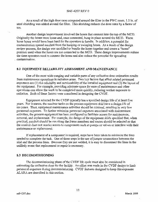
As a result of the high dose rates computed around the filter in the PWC room, 1.5 in. of steel shielding was added around the filter. This shielding reduces the dose rates by a factor of ten.
Another design improvement involved the hoses that connect into the top of the MCO. Originally the hoses were loose and, once connected, hung in place around the MCO. These loose hoses would have been hard for the operators to handle. In addition, a potential for contamination spread resulted from the hanging or swinging hoses. As a result of the design review process, the design was modified to bundle the hoses together and create a “home” position used when the hoses are not connected to the MCO. These design improvements reduce the time operators need to connect the hoses and also reduce the potential for spreading contamination.
8.2 EQUIPMENT RELIABILITY ASSESSMENT AND MAINTENANCE
One of the most wide-ranging and variable parts of any collective dose estimation results from maintenance operations in radiation areas. Two key factors that affect related personnel exposures are (1) the reliability and serviceability of the installed equipment and (2) the layout of the equipment. For example, providing adequate space for ease of maintenance and other operations can allow the work to be completed more quickly, reducing worker exposure to radiation. Both of these factors were considered in designing the CVDF.
Equipment selected for the CVDF typically has a specified design life of at least five years. For instance, the receiver tanks on the process equipment skid have a design life of ten years. Thus, equipment maintenance activities should be minimal, resulting in very low personnel exposure. To further minimize personnel exposure associated with maintenance activities, the process equipment has been configured to facilitate access for maintenance, removal, and replacement. For example, the design of the equipment skids specified that, when practical, conduit should be run along the frame members and routes should be selected so that the conduit does not restrict access to components such as pumps or valves or interfere with their maintenance or replacement.
If replacement of a component is required, steps have been taken to minimize the time needed to complete the task. One of these steps is the use ofjumper connections between the skid and the process lines. Because they are not welded, it is easy to disconnect the lines in the unlikely event that replacement or repair is necessary.
8.3 DECOMMISSIONING
The decommissioning phase of the CVDF life cycle must also be considered in estimating the collective dose for the facility. An effort was made in the CVDF design to limit personnel exposure during decommissioning. CVDF features designed to keep this exposure ALARA are described in this section.
snf-4207.doc 13
March 1999
SNF-4207 REV 0
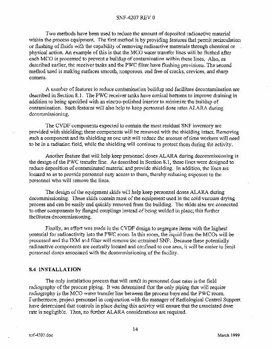
Two methods have been used to reduce the amount of deposited radioactive material within the process equipment. The first method is by providing features that permit recirculation or flushing of fluids with the capability of removing radioactive materials through chemical or physical action. An example of this is that the MCO water transfer lines will be flushed after each MCO is processed to prevent a buildup of contamination within these lines. Also, as described earlier, the receiver tanks and the PWC filter have flushing provisions. The second method used is making surfaces smooth, nonporous, and free of cracks, crevices, and sharp comers.
A number of features to reduce contamination buildup and facilitate decontamination are described in Section 8.1. The PWC receiver tanks have conical bottoms to improve draining in addition to being specified with an electro-polished interior to minimize the buildup of contamination. Such features will also help to keep personnel dose rates ALARA during decommissioning.
The CVDF components expected to contain the most residual SNF inventory are provided with shielding; these components will be removed with the shielding intact. Removing such a component and its shielding as one unit will reduce the amount of time workers will need to be in a radiation field, while the shielding will continue to protect them during the activity.
Another feature that will help keep personnel doses ALARA during decommissioning is the design of the PWC transfer line. As described in Section 8.1, these lines were designed to reduce deposition of contaminated material and provide shielding. In addition, the lines are located so as to provide personnel easy access to them, thereby reducing exposure to the personnel who will remove the lines.
The design of the equipment skids will help keep personnel doses ALARA during decommissioning. These skids contain most of the equipment used in the cold vacuum drying process and can be easily and quickly removed from the building. The skids also are connected to other components by flanged couplings instead of being welded in place; this further facilitates decommissioning.
Finally, an effort was made in the CVDF design to segregate items with the highest potential for radioactivity into the PWC room. In this room, the liquid from the MCOs will be processed and the IXM and filter will remove the entrained SNF. Because these potentially radioactive components are centrally located and confined to one area, it will be easier to limit personnel doses associated with the decommissioning of the facility.
8.4 INSTALLATION
The only installation process that will result in personnel dose rates is the field radiography of the process piping. It was determined that the only piping that will require radiography is the MCO water transfer line between the process bays and the PWC room. Furthermore, project personnel in conjunction with the manager of Radiological Control Support have determined that controls in place during this activity will ensure that the associated dose rate is negligible. Thus, no further ALARA considerations are required.
14 snf-4207.doc March 1999
SNF-4207 REV 0
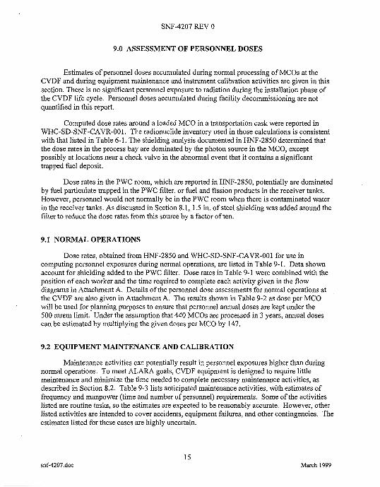
9.0 ASSESSMENT OF PERSONNEL DOSES
Estimates of personnel doses accumulated during normal processing of MCOs at the CVDF and during equipment maintenance and instrument calibration activities are given in this section. There is no significant personnel exposure to radiation during the installation phase of the CVDF life cycle. Personnel doses accumulated during facility decommissioning are not quantified in this report.
Computed dose rates around a loaded MCO in a transportation cask were reported in WHC-SD-SNF-CAVR-001. The radionuclide inventory used in those calculations is consistent with that listed in Table 6-1. The shielding analysis documented in HNF-2850 determined that the dose rates in the process bay are dominated by the photon source in the MCO, except possibly at locations near a check valve in the abnormal event that it contains a significant trapped fuel deposit.
Dose rates in the PWC room, which are reported in HNF-2850, potentially are dominated by fuel particulate trapped in the PWC filter, or fuel and fission products in the receiver tanks. However, personnel would not normally be in the PWC room when there is contaminated water in the receiver tanks. As discussed in Section 8.1, 1.5 in. of steel shielding was added around the filter to reduce the dose rates from this source by a factor of ten.
9.1 NORMAL OPERATIONS
Dose rates, obtained from HNF-2850 and WHC-SD-SNF-CAVR-001 for use in computing personnel exposures during normal operations, are listed in Table 9-1. Data shown account for shielding added to the PWC filter. Dose rates in Table 9-1 were combined with the position of each worker and the time required to complete each activity given in the flow diagrams in Attachment A. Details of the personnel dose assessments for normal operations at the CVDF are also given in Attachment A. The results shown in Table 9-2 as dose per MCO will be used for planning purposes to ensure that personnel annual doses are kept under the 500 mrem limit. Under the assumption that 440 MCOs are processed in 3 years, annual doses can be estimated by multiplying the given doses per MCO by 147.
9.2 EQUIPMENT MAINTENANCE AND CALIBRATION
Maintenance activities can potentially result in personnel exposures higher than during normal operations. To meet ALARA goals, CVDF equipment is designed to require little maintenance and minimize the time needed to complete necessary maintenance activities, as described in Section 8.2. Table 9-3 lists anticipated maintenance activities, with estimates of frequency and manpower (time and number of personnel) requirements. Some of the activities listed are routine tasks, so the estimates are expected to be reasonably accurate. However, other listed activities are intended to cover accidents, equipment failures, and other contingencies. The estimates listed for these cases are highly uncertain.
snf-4207.doc 15
March 1999

SNF-4207 REV 0
Table 9-1. General Locations and Dose Rates in the Cold Vacuum Drying Facility.
General location and operation condition
Flooded cask in CVDF process bay: Mezzanine at c1 m from cask Mezzanine at 1 to 3 m from cask Mezzanine at 3 to 5 m from cask Mezzanine at 25 m from cask Mezzanine with cask lid off,
MCO port plate on MCO port plate off
Main floor at c l m from cask Main floor at 1 to 3 m from cask Main floor at 3 to 5 m from cask Main floor >5 m from cask Main floor at drain port
Dry cask in CVDF process bay: Mezzanine at 4 m from cask Mezzanine at 1 to 3 m from cask Mezzanine at 3 to 5 m from cask Mezzanine at >5 m from cask Mezzanine with cask lid off,
MCO port plate on MCO port plate off
Main floor at c l m from cask Main floor at 1 to 3 m from cask Main floor at 3 to 5 m from cask Main floor >5 m from cask Main floor at drain port
Main floor at <I m from filter Main floor at 1 to 1.5 m from filter Main floor at 1.5 to 3.5 m from filter Main floor at >3.5 m from filter
*Dose rates were obtained from contour map: Shielding Analysis for the Cold Vacuum Drying Pm, and Attachment A of this report for details.
PWC room:
CVDF = Cold Vacuum Drying Facility. MCO = multi-canister overpack. PWC = process water conditioning.
Dose rate' (mremlh)
1 .oo 0.50 0.25 0.10 .
0.34 1.50 2.50 1 .oo 0.50 0.25 2.30
2.00 1 .oo 0.50 0.25
0.34 1.50 5.00 2.00 1 .oo 0.50 2.30
10.00 5.00 2.00 1.50
HNF-2850. t. See SNF-2850
snf-4207.doc 16
March 1999

SNF-4207 REV 0
Operator 1
Operator 2
Facility manager
Table 9-2. Cold Vacuum Drying Facility Personnel Exposure per Multi-Canister Overpack Processed.
25.4 6.01
14.7 0.01
0.81 0.01
QNQC
I RCT I 10.0 I 5.01 I
0.01 0.01
ITruck driver I 0.86 I 0.01 I
Total per process
lprocess engineer I 0.01 I 0.01 I
51.8 11.1
Total I 62.9 I I I
can be estimated by multiplying the given doses per MCO by 147. *Under the assumption that 440 MCOs are processed in 3 years, annual doses
CVDF = Cold Vacuum Dlying Facility PWC = process water conditioning. QA = quality assurance. QC = quality control. RCT = radiological control technician.
17 snf-4207.doc March 1999
SNF-4207 REV 0
Number of personnela Activity
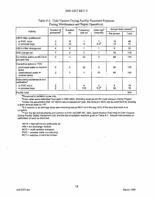
Table 9-3. Cold Vacuum Drying Facility Personnel Exposure During Maintenance and Repair Operations.
Duration Frequency Dose rate' dose (mrem)" (h) (per yr) (mrem'h) Per person 1 Total
HEPA filter qualification - in PWC room - in process bays
IXM change out
HEPA Filter change-out
Corrective action on MCOs in process bay
Corrective action in PWC
3 16 1 1 16 48 3 16 4 0.3' 19 57
4 8 1 1 8 32
7 8 2 1 16 112
2 2 22 2 88 176
- processed water in receiver
- unprocessed water in
Instrument maintenance and calibratione
tanks
receiver tanks
I i I 126 4 I 0.3' 2 1 388 I :: I - in PWC room - in process bays
2 2 22 2 88 176
2 2 2 20 80 160
Facility total
snf-4207.doc
853
18 March 1999
SNF-4207 REV 0
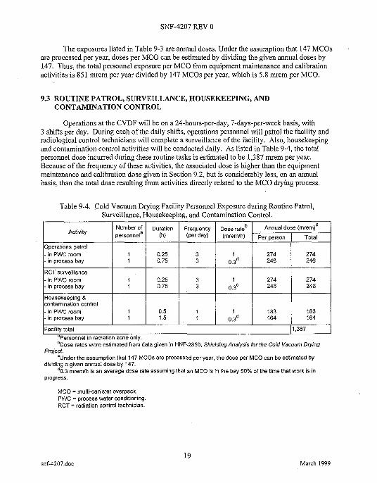
Activity
Operations patrol - in PWC room - in process bay
RCT surveillance - i n PWC room - in process bay
The exposures listed in Table 9-3 are annual doses. Under the assumption that 147 MCOs are processed per year, doses per MCO can be estimated by dividing the given annual doses by 147. Thus, the total personnel exposure per MCO from equipment maintenance and calibration activities is 851 mrem per year divided by 147 MCOs per year, which is 5.8 mrem per MCO.
Number of Duration Frequency Dose rateb Annual dose (mrem)c personnela (h) (Per day) (mremlh) per person Total
1 0.25 3 1 274 274 1 0.75 3 0.3d 246 246
1 0.25 3 1 274 274 1 0.75 3 0.3d 246 246
9.3 ROUTINE PATROL, SURVEILLANCE, HOUSEKEEPING, AND CONTAMINATION CONTROL
Operations at the CVDF will be on a 24-hours-per-day, 7-days-per-week basis, with 3 shifts per day. During each of the daily shifts, operations personnel will patrol the facility and radiological control technicians will complete a surveillance of the facility. Also, housekeeping and contamination control activities will be conducted daily. As listed in Table 9-4, the total personnel dose incurred during these routine tasks is estimated to be 1,387 mrem per year. Because of the frequency of these activities, the associated dose is higher than the equipment maintenance and calibration dose given in Section 9.2, but is considerably less, on an annual basis, than the total dose resulting from activities directly related to the MCO drying process.
Housekeeping 8 contamination control - in PWC room - in process bay
Table 9-4. Cold Vacuum Drying Facility Personnel Exposure during Routine Patrol, Surveillance, Housekeeping, and Contamination Control.
1 0.5 1 1 183 183 1 1.5 1 0.3d 164 164
Facility total 1,387
snf-4207.doc 19
March 1999
SNF-4207 REV 0
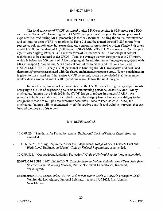
10.0 CONCLUSION
The total exposure of CVDF personnel during MCO processing is 62.9 mrem per MCO, as given in Table 9-2. Assuming that 147 MCOs are processed per year, the annual personnel exposure incurred during MCO processing is then 9,246 mrem. Adding the annual maintenance and calibration dose of 853 mrem given in Table 9-3 and the annual dose of 1,387 mrem from routine patrol, surveillance, housekeeping, and contamination control activities (Table 9-4) gives a total CVDF annual dose of 11,500 mrem. HNF-SD-SNF-PD-Ol l, Spent Nuclear Fuel Project Operations Staffing Plan, calls for a work force of 25 operators and 15 radiological control technicians to be stationed at the CVDF. Thus, the average worker dose per year is 287 mrem, which is below the 500 mrem ALARA design goal. In addition, travelling crews associated with MCO transport (15 operators, 5 radiological control technicians, and 5 drivers are listed in HNF-SD-SNF-PD-01 1) help CVDF personnel in handling the MCO transporter and cask, and there are 35 persons associated with the shared maintenance response crew. When consideration is given to this shared staff that assists CVDF personnel, it can be concluded that the average worker dose associated with CVDF operations is well below the ALARA goal.
In conclusion, this report demonstrates that the CVDF meets the regulatory requirements applying to the use of engineering controls for maintaining personnel doses ALARA. Many engineered features were included in the CVDF design to reduce dose rates ALARA. As potentially high dose rates were identified during the design phase, changes or additions to the design were made to mitigate the excessive dose rates. Also to keep doses ALARA, the engineered features will be augmented by administrative controls and training programs that are beyond the scope of this report.
11.0 REFERENCES
10 CFR 20, “Standards for Protection against Radiation,” Code of Federal Regulations, as amended.
10 CFR 72, “Licensing Requirements for the Independent Storage of Spent Nuclear Fuel and High-Level Radioactive Waste,” Code of Federal Regulations, as amended.
10 CFR 835, “Occupational Radiation Protection,” Code of Federal Regulations, as amended.
BNWL-236 SUPl, 1967, ISOSHLD-II: Code Revision to Include Calculation of Dose Rate from Shielded Bremsstrahlung Sources, Pacific Northwest Laboratories, Richland, Washington.
Breismeister, J. F., Editor, 1993, MCNP - A General Monte Carlo N-Particle Transport Code, Version 4a, Los Alamos National Laboratory report LA-12625, Los Alamos, New Mexico.
20 snf-4207.doc March 1999
SNF-4207 REV 0
DOE N5480.6,'DOE Radiological Control Manual, U.S. Department of Energy, Washington, D.C.
DOE Order 5480.23, Nuclear Safety Analysis Reports, U S . Department of Energy, Washington, D.C.
HNF-2850, 1998, Shielding Analysis for the Cold Vacuum Drying Project, Rev. 0, Fluor Daniel Hanford, Inc., Richland, Washington.
HNF-SD-SNF-CN-026, 1997, MCO Shield Plug Dose Rate Analysis, Rev. 0, Fluor Daniel Hanford, Inc., Richland, Washington.
HNF-SD-SNF-DB-003, 1998, Spent Nuclear Fuel Project Path Forward, Additional NRC Requirements, Rev. 4A, Fluor Daniel Hanford, Inc., Richland, Washington.
HNF-SD-SNF-PD-01 1, 1998, Spent Nuclear Fuel Project Operations Stafing Plan, Rev. 2, Fluor Daniel Hanford, Inc., Richland, Washington.
HNF-SD-SNF-SEL-002,1998, Spent Nuclear Fuel Project Cold Vacuum Drying Facility Safety Equipment List, Rev. 5 , Fluor Daniel Hanford, Inc., Richland, Washington.
HNF-SD-SNF-SP-0 12, 1997, Additional Guidance for Including Nuclear Safety Equivalency in the Canister Storage Building and the Cold Vacuum Drying Facility Final Safety Analysis Reports, Rev. 0, Fluor Daniel Hanford, Inc., Richland, Washington.
HNF-SD-SNF-TI-009, 1998,105-K Basin Material Design Basis Feed Description for Spent Nuclear Fuel Project Facilities, Rev. 1, Duke Engineering and Services Hanford, Richland, Washington.
HSRCM-I, 1994, Hanford Site Radiological Control Manual, Rev. 2, Westinghouse Hanford Company, Richland, Washington.
ICRP Publication 37, 1983, Cost-Benefit Analysis in the Optimization of Radiation Protection, International Commission on Radiological Protection, Elmsford, New York.
Nelson, J.V., 1996, Estimation of Neutron Dose Ratesfvom Nuclear Waste Packages (internal memo 8M730-JN-006, to J. R. Green dated March 8), Westinghouse Hanford Company, Richland, Washington.
NRC Regulatory Guide 8.8, 1978, Information Relevant to Ensuring that Occupational Radiation Exposures at Nuclear Power Stations will be as Low as Reasonably Achievable, Rev. 3, U. S. Nuclear Regulatory Commission, Washington, D.C.
SNF-2356, 1999, Spent Nuclear Fuel Project Cold Vacuum Drying Facility Operations Manual, Rev. 1, Fluor Daniel Hanford, Inc., Richland, Washington.
snf-4207.doc 21
March 1999
SNF-4207 REV 0
WHC-SD-MP-SWD-30001, 1996, Certification of MCNP Version 4A for WHC Computer Platforms, Rev. 8, Westinghouse Hanford Company, Richland, Washington.
WHC-SD-SNF-CAVR-001,1996, Recent Dose Rate Calculational Summay for N-Reactor Fuel Handling and Shippingfrom K-Basin, Rev. 0, Westinghouse Hanford Company, Richland, Washington.
WHC-SD-WM-UM-030, 1995, ISO-PC Version 1.98 - User's Guide, Rev. 0, Westinghouse Hanford Company, Richland, Washington.
22 snf-4207.doc March 1999

SNF-4207 REV 0
ATTACHMENT A
COLD VACUUM DRYING FACILITY WORKER RADIATION DOSE ASSESSMENT
snf-4207.doc A- 1
March 1999
snf-4207.doc
SNF-4207 REV 0
This page intentionally left blank.
A-2 March 1999

SNF-4207 REV 0
NHC Numatec
.Hanford Corporation Internal An SGNICogema, Inc. Company Memo
From: Process Engineering Phone: 372-3143 R3-86 Date: September 3, 1998 Subject: COLD VACUUM DRYING FACILITY WORKER RADIATION DOSE
ASSESSMENT
To: A. H. McNeil R3-86
cc:
References: (1)
W. C. Alaconis D. E. Bullock T. Choho J. E. Kurtz C. M. Miska C. C. Pitkoff C. Pili-Vhcens Project Files JJI FileiLB
R3-86
R3-86
R3-86
R3-26
R3-86
X3-61
R3-86
R3-11
JJI-98403
HNF-SD-SNF-DRD-dO2, 1998, Cold Vacuu m Drvine Facilitv Desim peauirements, Rev. 3, Fluor Daniel Hanford, Incorporated, Richland, Washington.
SNF-2356, 1998, mnt Nuclear Fue I Proiect - Cold Vacuum Fac iliE Ooerations Manual, Rev. Oa, Fluor Daniel Hanford, Incorporated, Richland, Washington.
HNF-2850, Shieldine Analvsis for the Cold Vacuum Drving Proiect, Rev. 0, Fluor Daniel Hanford, Incorporated, Richland, Washington.
H-1-82166, Cold Vacuum Drvine Facilitv Process Eauioment Skid Flow m, Fluor Daniel Hanford, Incorporated, Richland, Washington.
H-1-83766, Cold Vacuum Drvine Facilitv Process Svs tern P&ID, Fluor Daniel Hanford. Incorporated, Richland, Washington.
This letter documents the CVDF worker dose assessment that was done to support the CVDF ALARA analysis. Current C M F designs, operation sequences, staffing plans and radiation shielding analyses were used to perform the dose assessment. Using the CVDF project current process flow concepts and knowledge from CVDF Design Authorities and operational personnel, an assessment of the CVDF project radiological exposure and resource requirements was completed.
Assumutions
The current CVDF design requirements are specified in the CVDF DRD (Reference l), a description of the CVDF and its various systems is defined in the CVDF Operations Manual
snf-4207.doc A-3
March 1999

SNF-4207 REV 0
Personnel
Operator 1
Operator 2
CVDF Occupancy
Continuouslshift
Continuouslshift
I Facility Manager I Continuouslshift I HFT
Truck Driver
Process Engineer
Continuouslshift
Variable
Continuouslshift
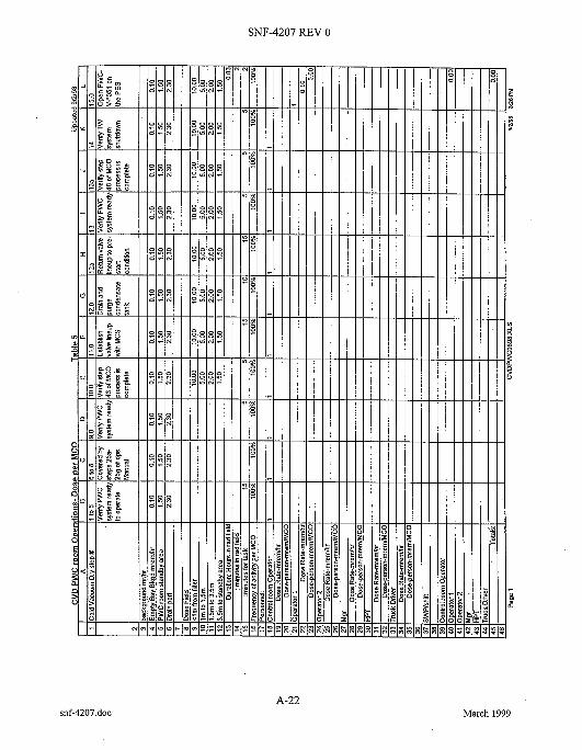
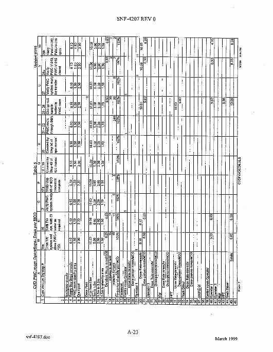
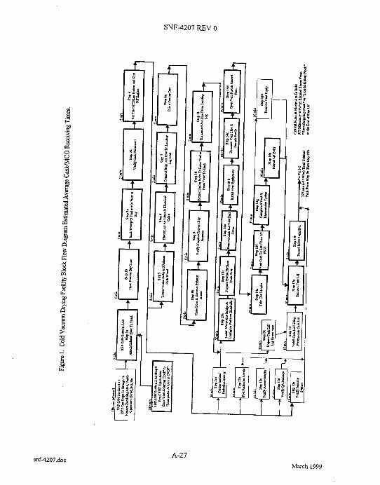
I QA/QC I Continuouslshift I The normal CVD and PWC process system operations are shown in the block flow'diagrams, Figures 1 through 4 (Attachment 3), process flow diagram (HI-1-82166). and defined on the system P&ID ( H-1-83766). The basic process concept utilized for the assessment is as follows.
Cold Vacuum Drying System Operations Overview:
Cold Vacuum Drying Facility Prerequisites for the Cask-Multi-Canister Overpack Transporter Receipt Operation and Normal Cold Vacuum Drying Process Operation (SNF-2356, section 3.4.1. step 1)
Cask-Multi-Canister Overpack Transporter Receipt Operation (SNF-2356, section 3.4.2, steps 2 through 13)
Cask Preparations for Cold Vacuum Drying - Cask Venting (SNF-2356, section 3.4.3, steps 14 and 15)
Cask Preparations for Cold Vacuum Drying - Cask Lid Removal (SNF-2356, section 3.4.4, steps 16 and 17)
Cask-Multi-Canister Overpack Preparations for Cold Vacuum Drying - Multi-Canister OverpackProcess HoodlSeal Ring Installation (SNF-2356, section 3.4.5, steps 18 and 19)
.
.
snf-4207.doc A-4
March 1999

SNF-4207 REV 0
NHC Numatec
. Hanford Corporation Internal An SGNKogema, Inc. Company Memo
. Multi-Canister Overpack Preparations for Cold Vacuum Drying -Vacuum and Purge System Hookup (SNF-2356, section 3.4.6, steps 20 through 22)
. Cask-Multi-Canister Overpack Preparations for Cold Vacuum Drying - Tempered Water System Hookup and Heatup (SNF-2356, section 3.4.7, steps 23 and 24)
Vacuum and Purge System Operation - Drain Operation (SNF-2356, section 3.4.8, step 25, section 3.4.9, step 26)
Vacuum and Purge System Operation - Vacuum/Purge Drying Operation (SNF-2356, section 3.4.10 through 3.4.16, steps 27 through 40)
Vacuum and Purge System Operation - Proof of Dryness Demonstration (SNF-2356, section 3.4.17, steps 41, section 3.4.18, step 42)
Vacuum and Purge System Operation - Cooldown to 25 'C (77 "F) Operation (SNF-2356, section 3.4.19, steps 43 and 44)
Multi-Canister Overpack Helium Leak Test (SNF-2356, section 3.4.20, steps 45 through 54)
Preparation of Cask for Depamre (SNF-2356, section 3.4.21, steps 55 through 57)
Preparation of Trailer for Transport (SNF-2356, section 3.4.22, steps 58 through 65)
Transport Cask-Multi-Canister Overpack Out of the Cold Vacuum Drying Facility (SNF-2356, section 3.4.23, steps 66 and 67)
.
.
.
.
.
.
Process Water Conditioning System Operation:
. Process Water Conditioning Vacuum Pumping and Receiving - Prerequisite (SNF-2356, section 3.5.1, steps 1 through 5)
Process Water Conditioning Vacuum Pumping and Receiving - MCO Bulk Water Draining (SNF-2356, section 3.5.2, steps 6 through 8)
Process Water Conditioning Vacuum Pumping and Receiving - VPS Condenser Tank Draining (SNF-2356, section 3.5.3, steps 9 through 12)
Process Water Conditioning Vacuum Pumping and Receiving -Tempered Water System Draining (SNF-2356, section 3.5.4, steps 13 through 16) Process Water Conditioning Vacuum Pumping and Receiving - Cask-MCO Annulus Draining (SNF-2356, section 3.5.5, steps 17 through 20)
Process Water Conditioning Impurity Removal (SNF-2356, section 3.5.6, steps 21 through 22)
.
.
.
. Process Water Conditioning E M Water Sampling (SNF-2356, section 3.5.7, steps 23 through 26)
A-5 snf-4207.doc March 1999
SNF-4207 REV 0
C M F General Location and Operation Condition
NKC Numatec
. Hanford Corporation Internal An SGNICogema, Inc. Company Memo
. Process Water Conditioning Transfer to PWC Holding Tank, PWC-TK-4001 (SNF-2356, section 3.5.8, steps 27 through 28)
Process Water Conditioning Transfer from PWC-TK-4001 to KW Basin Tractor Trailer (SNF- 2356, section 3.5.9, steps 29 through 33)
Process Water Conditioning Transfer Line Flushing (SNF-2356, section 3.5.10).
.
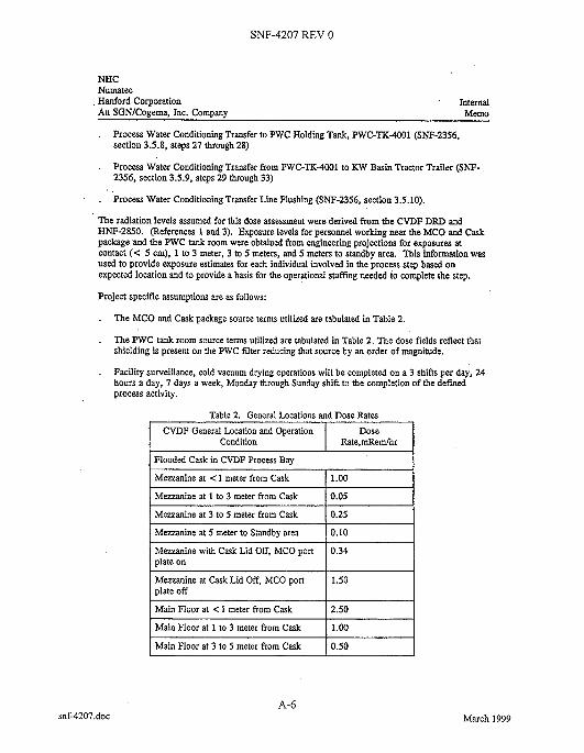
. The radiation levels assumed for this dose assessment were derived from the CVDF DRD and HNF-2850. (References 1 and 3). Exposure levels for personnel working near the MCO and Cask package and the PWC tank room were obtained from engineering projections for exposures at contact (< 5 cm), 1 to 3 meter, 3 to 5 meters, and 5 meters to standby area. This information was used to provide exposure estimates for each individual involved in the process step based on expected location and to provide a basis for the operational staffing needed to complete the step.
Project specific assumptions are as follows:
. The MCO and Cask package source terms utilized are tabulated in Table 2.
Dose Rate,mXem/hr
The PWC tank rmm source t e r n utilized are tabulated in Table 2. The dose fields reflect that shielding is present on the PWC filter reducing that source by an order of magnitude.
Mezzanine at 3 to 5 meter from Cask
Facility surveillance, cold vacuum drying operations will be completed on a 3 shifts per day, 24 hours a day, 7 days a week, Monday through Sunday shift to the completion of the defined process activity.
0.25
Main Floor at 3 to 5 meter from Cask
Mezzanine at < 1 meter from Cask
Mezzanine at 1 to 3 meter from Cask
1 .00
I 0.05
0.50
I 0.34 I MQzanine with Cask Lid Off, MCO port plate on
I lSO I Mezzanine at Cask Lid Off, MCO pon plate off
Main Floor at < 1 meter from Cask I 2.50 I Main Floor at 1 to 3 meter from Cask I 1.00 ~ I
A-6 snf-4207.doc March 1999
SNF-4207 REV 0
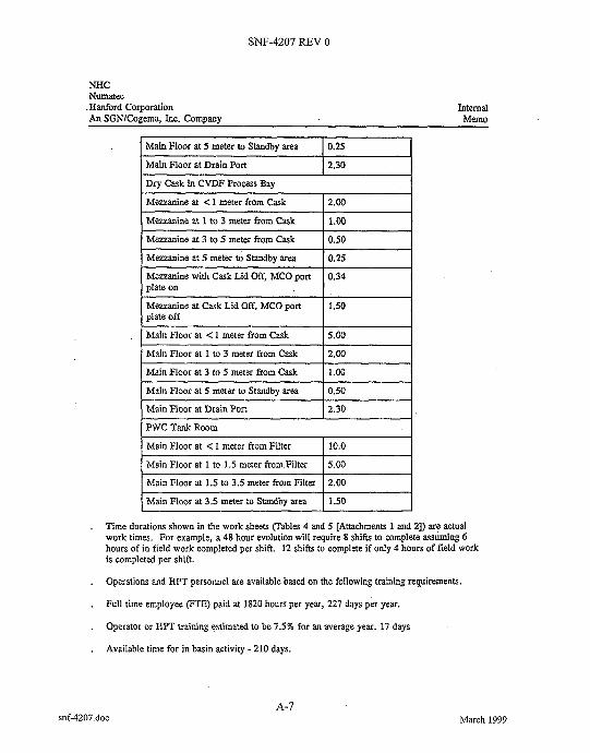
Main Floor at Drain Port
"C Numatec
.Hanford Corporation Internal An SGNICogema, Inc. Company Memo
2.30
I Main Floor at 5 meter to Standby area I 0.25 I
Mwanine at 1 to 3 meter from Cask
Mezzanine at 3 to 5 meter from Cask
Mwanine at 5 meter to Standby area
1.00
0.50
0.25
I Mezzanine at < 1 meter from Cask I 2.00 I
Mezzanine with Cask Lid Off, MCO port plate on
Mezzanine at Cask Lid Off, MCO port plate off
0.34
1.50
Main Floor at 5 meter to Standby area
Main Floor at < 1 meter from Cask
Main Floor at 1 to 3 meter from Cask
5.00
1 2.00
0.50
I Main Floor at 3 to 5 meter from Cask I 1.00 I
Main Floor at < 1 meter from Filter 10.0
Main Floor at 1.5 to 3.5 meter from Filter 2.00
. Time durations shown in the work sheets (Tables 4 and 5 [Attachments 1 and 21) are actual work times. For example, a 48 hour evolution will require 8 shifts to complete assuming 6 hours of in field work completed per shift. 12 shifts to complete if only 4 hours of field work is completed per shift.
Operations and HPT personnel are available based on the following training requirements.
Full time employee (FTE) paid at 1820 hours per year, 227 days per year.
Operator or HPT training estimated to be 7.5% for an average year. 17 days
Available time for in basin activity - 210 days.
.
.
.
.
snf-4207.doc A-7
March 1999
SNF-4207 REV 0
Operator 1
Operator 2 .
Facility Manager
NHC Numatec . Hanford Corporation Internal An SGNICogema, Inc. Company Memo
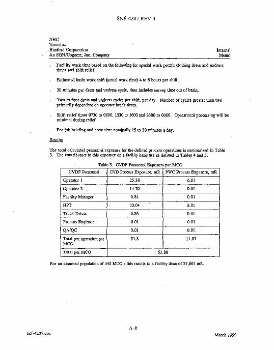
. Facility work time based on the following for special work permit clothing dress and undress times and shift relief.
Estimated basin work shift (actual work time) 4 to 6 hours per shift.
30 minutes per dress and undress cycle, time includes survey time out of basin.
Two to four dress and undress cycles per shift, per day. Number of cycles greater than two primarily dependent on operator break times.
Shift relief times 0730 to 0800, 1530 to 1600 and 2300 to oo00. Operational processing will be minimal during relief.
Pre-job briefing and crew time nominally 15 to 30 minutes a day.
.
.
.
.
.
25.38 6.01
14.70 0.01
0.81 0.01
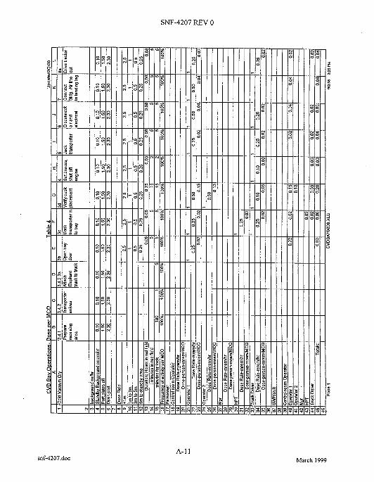
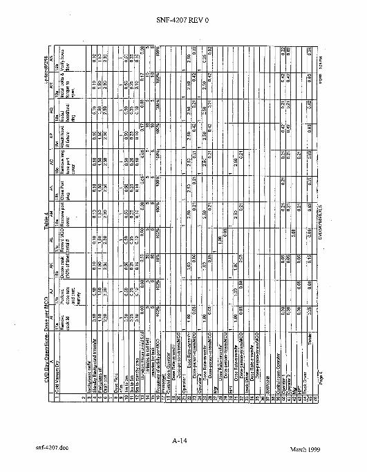
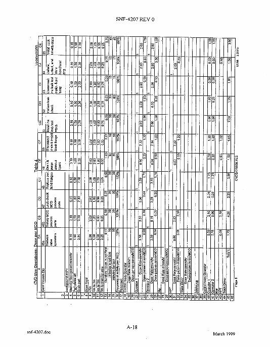
The total calculated personnel exposure for the defined process operations is summarized in Table 3. The contributors to this exposure on a facility basis are as defined in Tables 4 and 5.
Table 3. CVDF Personnel Exposure per MCO CVDF Personnel I CVD Process Exposure, mR [ PWC Process Exposure. mR
HPT 10.04 5.01
Truck Driver 0.86 0.01
Process Engineer
For an assumed population of 440 MCOs this results in a facility dose of 27,667 mR.
0.01 0.01
snf-4207.doc
QAJQC
A-8
0.01 ’ I 0.01
March 1999
Total per operation per MCO
Total D M MCO
51.8 1 1.07
62.88

SNF-4207 REV 0
"C Numatec . Hanford Corporation An SGN/Co.eema. h c . COmDanV
Internal Memo
ACknOWledem&
The team members listed below provided the exchange of knowledge and information which made the dose and resource integration effort a workable task. Without their work and experience this effort would have failed.
Team Members: Walt Alaconis CVDF Operations Dave Bullock CVDF Operations John J Irwin CVDF Design Authority
If you have any questions, please call Mr. J. J. Win on 372-3743.
//$LA J. . Irwin, SNF Project CVDF Design Authority Process Engineering
bmb
Attachments 3
snf-4207.doc A-9
March 1999

SNF-4207 REV 0
JJI-98-003
ATTACHMENT 1
Table 4
consisting o f 11 pages, including cover page
A-10 snf-4207.doc March 1999
SNF-4207 REV 0
A-1 1 snf-4207.doc March 1999

SNF-4207 REV 0
A-I2 snf-4207.doc March 1999

SNF-4207 REV 0
A-I3 snf-4207.doc March 1999
SNF-4207 REV 0
A-14 snf-4207.doc March 1999

SNF-4207 REV 0
snf-4207.doc A-15
March 1999

SNF-4207 REV 0
snf-4207.doc A-16
March 1999

SNF-4207 REV 0
snf-4207.doc A-17
March 1999
SNF-4207 REV 0
snf-4207.doc
O - N O P V ) ( O F """NC.
A-18 March 1999

SNF-4207 REV 0
A-19 snf-4207.doc March 1999

SNF-4207 REV 0
A-20 snf-4207.doc March 1999
SNF-4207 REV 0
JJI-98-003
ATTACHMENT 2
Table 5
consisting o f 5 pages', including cover page
March 1999 snf-4207.doc A-2 1
SNF-4207 REV 0
A-22 snf-4207.doc March 1999
SNF-4207 REV 0
A-23 snf-4207.doc March 1999

SNF-4207 REV 0
snf-4207.doc A-24
March 1999

SNF-4207 REV 0
9
8
A-25 snf-4207.doc March 1999

SNF-4207 REV 0
JJI-98-003
ATTACHMENT 3
Figures 1 through 4
consisting o f 5 pages
snf-4207.doc A-26
March 1999
SNF-4207 REV 0
z B
snf-4207.doc A-27
March 1999

SNF-4207 REV 0
.I 8 I' x
f I
A
snf-4207.doc A-28
March 1999
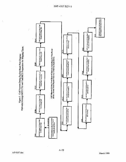
SNF-4207 REX 0
snf-4207.doc A-29
March 1999

SNF-4207 REV 0
March 1999

DISTRIBUTION SHEET To I From I Page 1 of 1
Distribution Nuclear Safety Date 4/1/99 Project Titlemork Order EDTNo. 624300
W. C. Alaconis R3-86 X
J. R. Brehm R3-26 X
SNF-4207, Rev. 0 Design Features of the Cold Vacuum Drying Facility to Keep Worker Doses as Low as Reasonably Achievable
S. A. Brisbin T. Choho
ECNNo. N/A
R3-86 X R3-86 X
Text
Attach Name MSIN WithAU Textonly
S. B. Hanington R3-26 X J. J. Irwin R3-86 X
EDT/ECN only
Appendix M Y
S. F. Kessler J. E. Kurtz S. L. Mischke C. R. Miska J. V. Nelson (2)
R3-26 X X3-68 X R3-86 X R3-86 X R3-26 X
C. C. Pitkoff R3-86 X R. Whitehurst R3-86 X SNF Proiect Files R3-11 X
A-6000-135 (01193) WEF067