4-overcoming the influence of human shadowing and ... · obstacles via modified building using...
TRANSCRIPT
Journal of Communication and Computer 13 (2016) 90-101 doi:10.17265/1548-7709/2016.02.004
Overcoming the Influence of Human Shadowing and
Obstacles via Modified Building Using Frequency
Selective Wallpapers for 60 GHz
Nidal Qasem, Emran Ali Aldorgam, and Hadeel Yaseen Alzou’bi
Department of Electronics and Communications Engineering, Al-Ahliyya Amman University, 19328, Amman, Jordan
Abstract: The growing demand for a very high speed and bandwidth over wireless communications makes the millimeter wave (mm-wave) “60 GHz” a great choice to be studied and used in order to achieve this desire. While the propagating signal of this
frequency can be easily blocked by any obstacle or body that faces it. This paper aims to solve this problem by using the SL (square
loop) FSS (frequency selective surfaces) in such a way to provide a stronger reflected signal to those shadowed positions as a result from the variety of the signal paths and enhancing the received signal power. So, minimizing the effect of human bodies that can attenuate 60 GHz signal.
Keywords: 60 GHz, band-stop, frequency selective surface, human modeling, millimeter wave.
1. Introduction
The development of wireless communications is
stimulated by the consumer desire for access to
information and entertainment. While
contemporaneity unlicensed systems support moderate
levels of wireless data traffic, as seen in Bluetooth and
WLANs (wireless local area networks). Current
technology is unable to supply data rates comparable
to wired standards like GbE (Gigabit Ethernet) and
HDMI (high definition multimedia interface) [1]. As
result of that data rates or bandwidths are never
enough, while the wireless multimedia distribution
market is ever growing [2]. So, an obvious solution to
this problem is to resort to the 60 GHz band, where
bandwidth is abundantly available [3].
Since the wavelength at 60 GHz is 5 mm which is
too small, obstacles such humans and furniture can
block links easily. For example, blockage by a human
can affect the link budget communication by 20-30
dB. So, movements of humans might cause a
Corresponding author: Nidal Eyad Qasem, Ph.D., assistant
professor, research fields: antennas, frequency selective surfaces, propagation control within buildings, ultra-wide band.
discontinuous blockage of millimeter wave links [4].
So, this paper suggests a novel technique that will
control the propagation of indoor wireless
environment at 60 GHz band by blocking the 60 GHz
signal from propagating inside the area of interest
using SL FSS to provide a stronger reflected signal as
well as providing multipath propagation due to the
variety of signal paths.
This paper shows an introduction of FSS. ECM
(equivalent circuit model) analysis technique is
mentioned in details and applied on the SL FSS. Next,
a scenario with only one room is presented with and
without SL FSS to check its effect on improving the
received signal power in presence of humans. Then,
another scenario is created inside corridor and
performed without SL FSS, with SL FSS and PEC
(perfect electric conductor), and with 45o inclined
PEC. Finally, the open area scenario is studied in the
presence and absence of SL FSS to show its effect on
the mean time of arrival and delay spread values.
2. Frequency Selective Surfaces
FSSs (frequency selective surfaces) are planar
D DAVID PUBLISHING
Overcoming the Influence of Human Shadowing and Obstacles via Modified Building Using Frequency Selective Wallpapers for 60 GHz
91
periodic structures which exhibit reflection and/or
transmission properties as a function of frequency.
The surface consists of thin conducting elements,
usually printed on dielectric substrates for support. In
general, the FSS structures can be divided into
patch-type or aperture-type metallic elements, being
periodic in either a one or two dimensional array.
Based on the element geometry, FSSs have four
operation modes: low- pass, high-pass, band-pass, and
band-stop filter [5]. FSS is now used in many fields in
military applications, antennas, medical applications,
and wireless communications security [6-12].
FSSs have many shapes and geometries. The most
common shapes are: square loops, dipoles, tripoles,
cross dipoles, Jerusalem crosses, and rings [5].
Previous researches showed that the SL FSS has the
best performance and stability to work within the
angular sensitivity, cross polarization TE (transverse
electric) or TM (transverse magnetic) modes, and
small band separation [13].
In order to test SL FSS, ECM has been considered
as the simple method. The first usage of ECM
technique and first applied to frequency selective
circuits was by Anderson [14]. The advantage of ECM
is that it can quickly characterize the FSS response
with varying element dimensions. On other hand,
ECM cannot be used to predict the performance of the
sophisticated shapes other than simple shapes like SL
FSS [15].
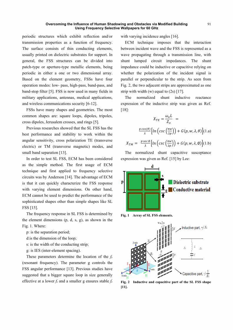
The frequency response in SL FSS is determined by
the element dimensions (p, d, s, g), as shown in the
Fig. 1. Where:
p: is the separation period;
d:is the dimension of the loop;
s: is the width of the conducting strip;
g: is IES (inter-element spacing).
These parameters determine the location of the fr
(resonant frequency). The parameter g controls the
FSS angular performance [13]. Previous studies have
suggested that a bigger square loop in size generally
effective at a lower fr and a smaller g ensures stable fr
with varying incidence angles [16].
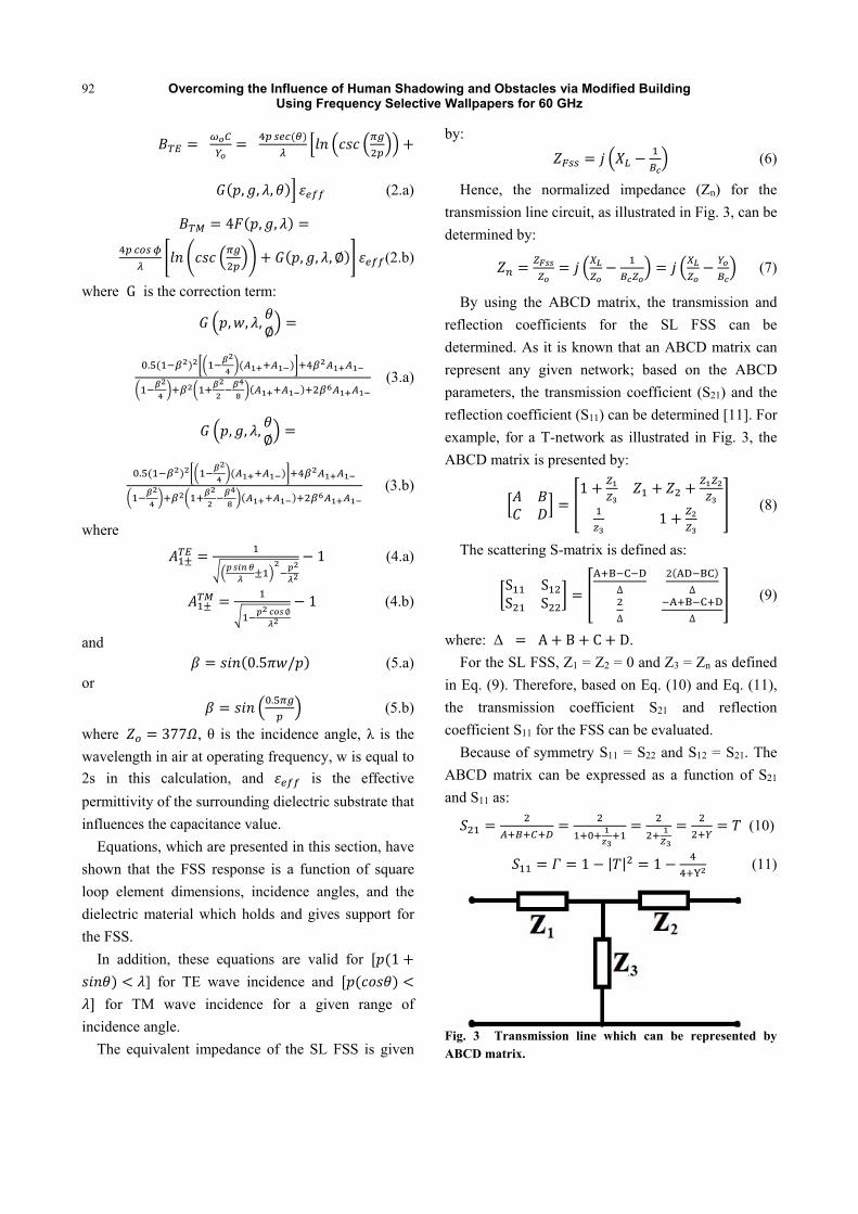
ECM technique imposes that the interaction
between incident wave and the FSS is represented as a
wave propagating through a transmission line, with
shunt lumped circuit impedances. The shunt
impedance could be inductive or capacitive relying on
whether the polarization of the incident signal is
parallel or perpendicular to the strip. As seen from
Fig. 2, the two adjacent strips are approximated as one
strip with width (w) equal to (2s) [17].
The normalized shunt inductive reactance
expression of the inductive strip was given as Ref.
[18]:
, , , (1.a)
∅
, , , ∅ (1.b)
The normalized shunt capacitive susceptance
expression was given as Ref. [15] by Lee:
Fig. 1 Array of SL FSS elements.
Fig. 2 Inductive and capacitive part of the SL FSS shape [11].
Overcoming the Influence of Human Shadowing and Obstacles via Modified Building Using Frequency Selective Wallpapers for 60 GHz
92
, , , (2.a)
4 , ,
, , , ∅ (2.b)
where G is the correction term:
, , ,∅
. (3.a)
, , ,∅
. (3.b)
where
1 (4.a)
∅1 (4.b)
and 0.5 / (5.a)
or .
(5.b)
where 377 , θ is the incidence angle, λ is the
wavelength in air at operating frequency, w is equal to
2s in this calculation, and is the effective
permittivity of the surrounding dielectric substrate that
influences the capacitance value.
Equations, which are presented in this section, have
shown that the FSS response is a function of square
loop element dimensions, incidence angles, and the
dielectric material which holds and gives support for
the FSS.
In addition, these equations are valid for 1
] for TE wave incidence and
for TM wave incidence for a given range of
incidence angle.
The equivalent impedance of the SL FSS is given
by:
(6)
Hence, the normalized impedance (Zn) for the
transmission line circuit, as illustrated in Fig. 3, can be
determined by:
(7)
By using the ABCD matrix, the transmission and
reflection coefficients for the SL FSS can be
determined. As it is known that an ABCD matrix can
represent any given network; based on the ABCD
parameters, the transmission coefficient (S21) and the
reflection coefficient (S11) can be determined [11]. For
example, for a T-network as illustrated in Fig. 3, the
ABCD matrix is presented by:
1
1 (8)
The scattering S-matrix is defined as:
S SS S
∆ ∆
∆ ∆
(9)
where: Δ A B C D.
For the SL FSS, Z1 = Z2 = 0 and Z3 = Zn as defined
in Eq. (9). Therefore, based on Eq. (10) and Eq. (11),
the transmission coefficient S21 and reflection
coefficient S11 for the FSS can be evaluated.
Because of symmetry S11 = S22 and S12 = S21. The
ABCD matrix can be expressed as a function of S21
and S11 as:
(10)
1 | | 1 (11)
Fig. 3 Transmission line which can be represented by ABCD matrix.
Overcoming the Influence of Human Shadowing and Obstacles via Modified Building Using Frequency Selective Wallpapers for 60 GHz
93
3. Simulation Results Using MATLAB
MATLAB is a system used to solve the theoretical
equations for ECM. For SL elements, resonance
occurs when each half loop acts as a dipole [19, 20].
The rule of thumb in designing the loop circumference
is to make it approximately equal the resonant
frequency wavelength (60 GHz). Basic design rules
for SL FSS element dimensions are given along with
equations for the ECM. Where its dimensions
are: p 1.4 , s 0.1 , d 1.2 , g
0.2 , and 2.
Figs. 4 and 5 show the frequency response for
TE-mode and TM-mode incidence respectively. The
result at normal incident between them is identical
because the SL FSS shape has a symmetric geometry.
4. Simulation Results Using CST (Computer Simulation Technology) MWS (Microwave Studio)
As discussed in Section 3, the ECM has been used
just as a design tool which helped to quickly identify
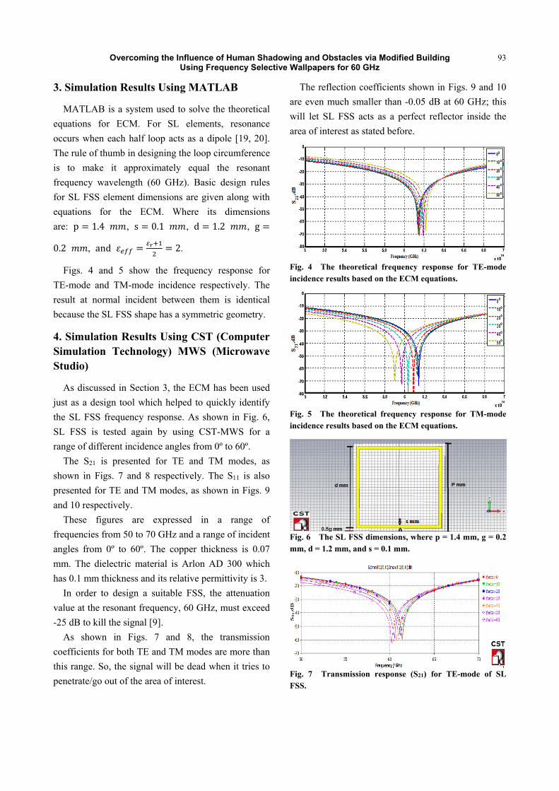
the SL FSS frequency response. As shown in Fig. 6,
SL FSS is tested again by using CST-MWS for a
range of different incidence angles from 0º to 60º.
The S21 is presented for TE and TM modes, as
shown in Figs. 7 and 8 respectively. The S11 is also
presented for TE and TM modes, as shown in Figs. 9
and 10 respectively.
These figures are expressed in a range of
frequencies from 50 to 70 GHz and a range of incident
angles from 0º to 60º. The copper thickness is 0.07
mm. The dielectric material is Arlon AD 300 which
has 0.1 mm thickness and its relative permittivity is 3.
In order to design a suitable FSS, the attenuation
value at the resonant frequency, 60 GHz, must exceed
-25 dB to kill the signal [9].
As shown in Figs. 7 and 8, the transmission
coefficients for both TE and TM modes are more than
this range. So, the signal will be dead when it tries to
penetrate/go out of the area of interest.
The reflection coefficients shown in Figs. 9 and 10
are even much smaller than -0.05 dB at 60 GHz; this
will let SL FSS acts as a perfect reflector inside the
area of interest as stated before.
Fig. 4 The theoretical frequency response for TE-mode incidence results based on the ECM equations.
Fig. 5 The theoretical frequency response for TM-mode incidence results based on the ECM equations.
Fig. 6 The SL FSS dimensions, where p = 1.4 mm, g = 0.2 mm, d = 1.2 mm, and s = 0.1 mm.
Fig. 7 Transmission response (S21) for TE-mode of SL FSS.
Overcoming the Influence of Human Shadowing and Obstacles via Modified Building Using Frequency Selective Wallpapers for 60 GHz
94
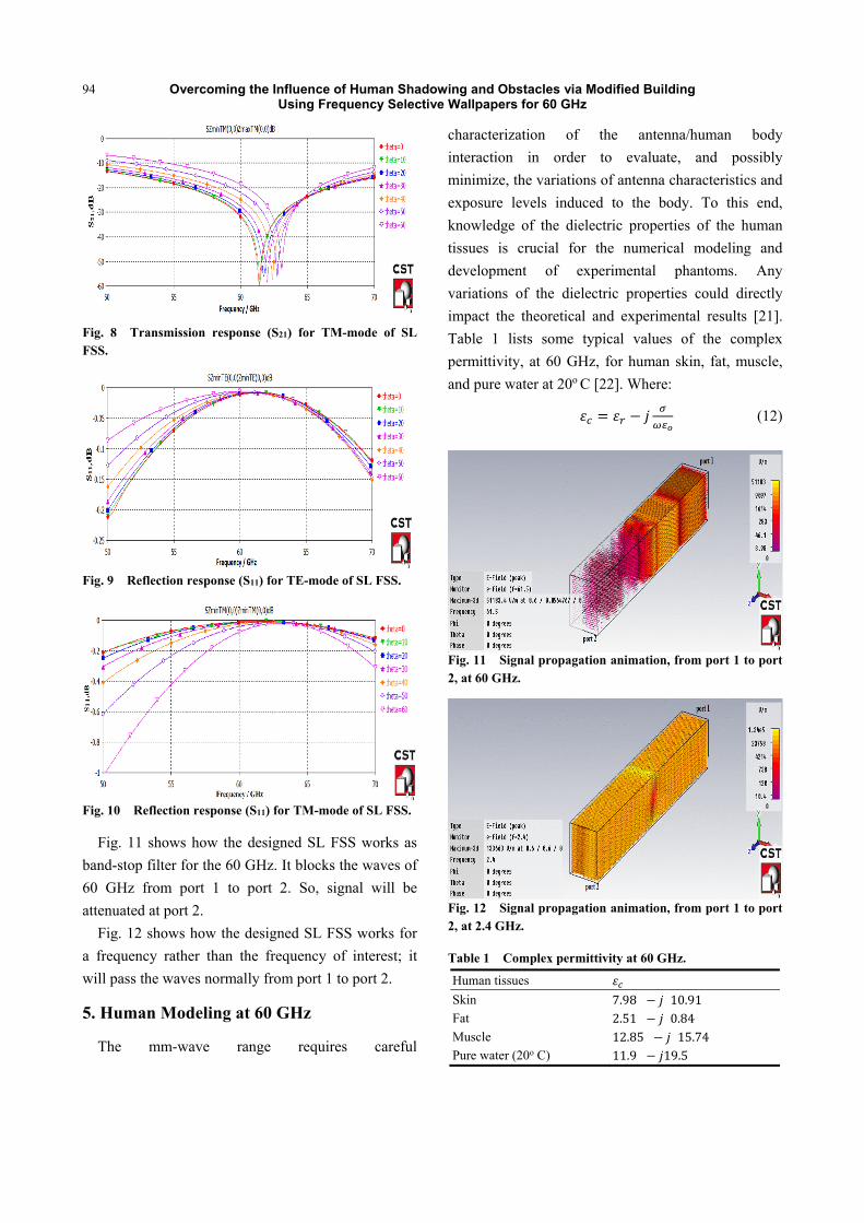
Fig. 8 Transmission response (S21) for TM-mode of SL FSS.
Fig. 9 Reflection response (S11) for TE-mode of SL FSS.
Fig. 10 Reflection response (S11) for TM-mode of SL FSS.
Fig. 11 shows how the designed SL FSS works as
band-stop filter for the 60 GHz. It blocks the waves of
60 GHz from port 1 to port 2. So, signal will be
attenuated at port 2.
Fig. 12 shows how the designed SL FSS works for
a frequency rather than the frequency of interest; it
will pass the waves normally from port 1 to port 2.
5. Human Modeling at 60 GHz
The mm-wave range requires careful
characterization of the antenna/human body
interaction in order to evaluate, and possibly
minimize, the variations of antenna characteristics and
exposure levels induced to the body. To this end,
knowledge of the dielectric properties of the human
tissues is crucial for the numerical modeling and
development of experimental phantoms. Any
variations of the dielectric properties could directly
impact the theoretical and experimental results [21].
Table 1 lists some typical values of the complex
permittivity, at 60 GHz, for human skin, fat, muscle,
and pure water at 20o C [22]. Where:
(12)
Fig. 11 Signal propagation animation, from port 1 to port 2, at 60 GHz.
Fig. 12 Signal propagation animation, from port 1 to port 2, at 2.4 GHz.
Table 1 Complex permittivity at 60 GHz.
Human tissues
Skin 7.98 10.91
Fat 2.51 0.84
Muscle 12.85 15.74
Pure water (20o C) 11.9 19.5

Overcoming the Influence of Human Shadowing and Obstacles via Modified Building Using Frequency Selective Wallpapers for 60 GHz
95
: Complex permittivity;
: Relative permittivity;
: Angular velocity measured in radians per
second;
: Free space permittivity, which equals
8.85x10⁻¹² F/m.
There are two models to simulate the human body
shadowing in an indoor environment. The first model
is known as “Phantom Human” and the other is called
“Salty-Lite”. In general, the human body is
represented as a parallelepiped circumscribed with
Salty-Cylinder model. The lengths of sides of the
basic rectangle will be equal to 0.305 m, the height is
equal to 1.7 m, and the thickness is equal to 0.305m
[5, 23]. In this work, the human body represented as a
parallelepiped circumscribed which contains skin, fat,
muscles, and a cylinder with a pure water at 20o C, as
shown in Fig. 13.
6. Simulation Results Using “Wireless InSite” Software
“Wireless InSite” is the software tool used to give
the closest scenario for signals propagating from Tx
(transmitter) to Rx (Receiver) inside the area of study
[24]. The S11 and S21 parameters values for designed
SL FSS have been exported to “Wireless InSite”.
A small area of interest with only one room which
has been investigated with and without SL FSS to
check its effect on reflecting the frequency of interest
of this study and improving the received signal power
in presence of humans. The comparison between
scenarios, with and without SL FSS, has shown how
the SL FSS affected the signal propagation and
enhanced the received signal power.
7. Open Area Scenario
One room with dimensions 15×10 m is considered.
SL FSS is attached on the wall scenario in order to
band-stop 60 GHz. SL FSS is placed away from the
wall by λ/10 in order to eliminate the coupling effect
[11].
The area of interest has an omnidirectional antenna
as a route of Rx’s with a sensitivity of -64 dBm [25].
The height of Rx’s is 1 m and the spaces between the
grid antennas of Rx’s are 0.5 m. Tx has directional
antenna with input power 10 dBm and gain of 14 dBi.
The height of Tx is 2.5 m above the floor which is
mounted on the ceiling. The electric parameters of the
materials used in the room scenario are presented in
Table 2 [24].
A. First Case without SL FSS Wallpaper
Fig. 14 shows the 2D view of the open area
scenario with many persons standing randomly
around. As well, this scenario consists of Tx and five
route Rx’s, each one has six points, the whole distance
between them is 0.5 m, 0.1 m between each pair, that
were arranged behind the person.
As shown in Fig. 15, the black parallelepiped
represents a human which stands in the room with no
SL FSS attached on the wall (normal case).
Fig. 13 The human model used in this study.
Table 2 Electrical parameters used for building interfaces.
The user interface Material Relative electrical permittivity, εr Conductivity, σ (S/m) Thickness, (m)
Walls Brick 4.44 0.001 0.150
Doors Wood 5 0 0.03
Windows Glass 2.4 0 0.003
Ceiling & floor Concrete 15 0.015 0.3

Overcoming the Influence of Human Shadowing and Obstacles via Modified Building Using Frequency Selective Wallpapers for 60 GHz
96
Fig. 14 2D view for the open area scenario.
Fig. 15 3D view for the open area scenario with no SL FSS.
By tracking the strength of the propagating signal
from Tx to Rx’s, as an example Rx-route 3, the
received 60 GHz signal power is very low because of
the effect of human which will attenuate the
propagating signal, as shown in Fig. 16.
B. Second Case with SL FSS Wallpaper
In this case, SL FSS is attached on the wall, as
shown in Fig. 17. The SL FSS here will work as a
good reflector for the 60 GHz signal, and denies the
signal getting out of the room, which will minimize
the effect of human in attenuating 60 GHz signal. By
tracking the propagating signal from Tx to Rx-route 3,
the received 60 GHz signal power will be much higher
than first case where no SL FSS is around, as shown
in Fig. 18.
To prove the enhancement in the received signal
power by adding SL FSS, comparisons between
presence and absence of the SL FSS at every Rx point
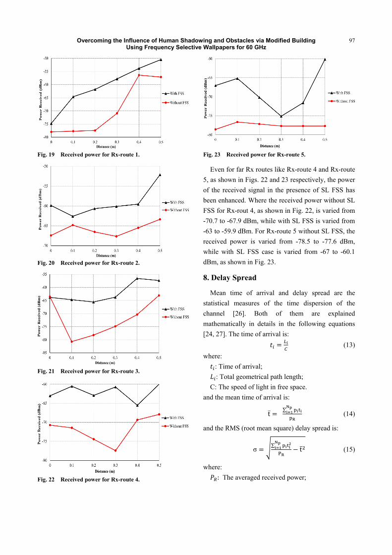
have been illustrated in Figs. 19-23. As shown in
Fig. 19, the received power for Rx-route 1, without SL
FSS, is varied from -77.9 to -57.1 dBm, while with SL
FSS case is varied from -74.7 to -50.4 dBm, where all
points have been enhanced.
As shown in Fig. 20, the received power with the
no presence of SL FSS is varied from -67.4 to -63.3
dBm, while in the presence of SL FSS is varied from
-59.8 to -52.1 dBm.
As shown in Fig. 21, the received power without SL
FSS case is varied from -63.5 to -63 dBm, while in
case of SL FSS around is varied from -63.8 to -57.3
dBm.
Fig. 16 The power of maximum 3 propagating paths from Tx to Rx-route 3 without SL FSS.
Fig. 17 3D view for the open area scenario with SL FSS.
Fig. 18 The power of maximum 3 propagating paths from Tx to Rx-route 3 with SL FSS.
Overcoming the Influence of Human Shadowing and Obstacles via Modified Building Using Frequency Selective Wallpapers for 60 GHz
97
Fig. 19 Received power for Rx-route 1.
Fig. 20 Received power for Rx-route 2.
Fig. 21 Received power for Rx-route 3.
Fig. 22 Received power for Rx-route 4.
Fig. 23 Received power for Rx-route 5.
Even for far Rx routes like Rx-route 4 and Rx-route
5, as shown in Figs. 22 and 23 respectively, the power
of the received signal in the presence of SL FSS has
been enhanced. Where the received power without SL
FSS for Rx-rout 4, as shown in Fig. 22, is varied from
-70.7 to -67.9 dBm, while with SL FSS is varied from
-63 to -59.9 dBm. For Rx-route 5 without SL FSS, the
received power is varied from -78.5 to -77.6 dBm,
while with SL FSS case is varied from -67 to -60.1
dBm, as shown in Fig. 23.
8. Delay Spread
Mean time of arrival and delay spread are the
statistical measures of the time dispersion of the
channel [26]. Both of them are explained
mathematically in details in the following equations
[24, 27]. The time of arrival is:
(13)
where:
: Time of arrival;
: Total geometrical path length;
C: The speed of light in free space.
and the mean time of arrival is:
t̅ ∑
(14)
and the RMS (root mean square) delay spread is:
σ∑
t̅ (15)
where:
: The averaged received power;

Overcoming the Influence of Human Shadowing and Obstacles via Modified Building Using Frequency Selective Wallpapers for 60 GHz
98
: The number of paths;
: The time averaged power in watts of the i
path.
In this paper, the open area scenario is studied in
the presence and absence of SL FSS, in order to show
the effect of adding SL FSS to the mean time of
arrival and delay spread values. In order to accomplish
this, two Rx routes have been taken which are
Rx-route 1 and Rx-route 3.
As shown in Fig. 24, the average of the mean time
of arrival in FSS case for Rx-route 1 was 37.5 ns. The
minimum value was 13.2 ns, and the maximum value
was 61.8 ns. While without FSS, the average was
25.85 ns. The minimum value was 10.7 ns and the
maximum value was 41 ns. As a result, these values
are within the acceptable range for 60 GHz [25]. Also,
the mean time of arrival with FSS is higher than no
FSS due to the richness in multipath in FSS case.
As shown in Fig. 25, the average of mean time of
arrival in FSS case for Rx-route 3 was 53.15 ns, while
with no FSS case was 51.1 ns.
As shown in Fig. 26, the average of delay spread
for Rx-route 1 in FSS case was 20.9 ns, while with no
FSS was 13.2 ns.
As shown in Fig. 27, the average of delay spread in
FSS case for Rx-route 3 was 15.5 ns, while with no
FSS was 10.8 ns.
9. Corridor Scenario
In this scenario, an L-shape corridor will be studied
with a directional horn antenna at Tx and Rx. The
input power for Tx is 10 dBm, Tx height is 1.5 m, Rx
height is 2 m, Rx is 0.5 m route, and the spacing
between each point is 0.1 m. The total number of
points is six. Simulations have been done using
“Wireless InSite” and performed without SL FSS,
with SL FSS and PEC, and with 45o inclined PEC
plane, as shown in Fig. 28. The dimension of SL FSS
and PEC is 3×3 m. These cases were studied in order
to show the impact of adding SL FSS and PEC on the
received signal power.
The first study case is a corridor without SL FSS, as
shown in Fig. 29. The second study case is a corridor
with SL FSS and PEC, as shown in Figs. 30 and 31
respectively.
Fig. 24 Mean time of arrival for Rx-route 1.
Fig. 25 Mean time of arrival for Rx-route 3.
Fig. 26 RMS delay spread for Rx-route 1.

Overcoming the Influence of Human Shadowing and Obstacles via Modified Building Using Frequency Selective Wallpapers for 60 GHz
99
Fig. 27 RMS delay spread for Rx-route 3.
(a) Without SL FSS.
(b) With SL FSS and PEC.
(c) With 45o inclined PEC plane.
Fig. 28 2D view of L-shape corridor scenario.
Fig. 29 3D view of L-shape corridor scenario without SL FSS.
Fig. 30 3D view of L-shape corridor scenario with SL FSS and PEC.
Fig. 31 3D view of L-shape corridor scenario with 45o inclined PEC.
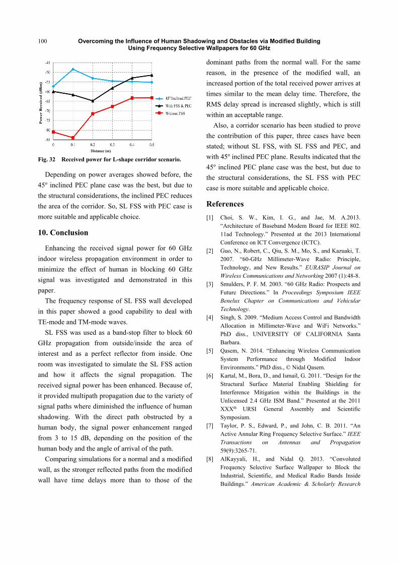
As shown in Fig. 32, the power of the received
signal without SL FSS case is varied from -80.9 to
-65.9 dBm, while with SL FSS and PEC case is varied
from -59.9 to -51.1 dBm. In the case of inclined PEC,
the power of the received signal is varied from -57.2
to -49.9 dBm. The average of the received signal
power without SL FSS, with SL FSS and PEC, and
with inclined PEC case was -68.542, -57.295, and
-51.609 dBm respectively.
Overcoming the Influence of Human Shadowing and Obstacles via Modified Building Using Frequency Selective Wallpapers for 60 GHz
100
Fig. 32 Received power for L-shape corridor scenario.
Depending on power averages showed before, the
45o inclined PEC plane case was the best, but due to
the structural considerations, the inclined PEC reduces
the area of the corridor. So, SL FSS with PEC case is
more suitable and applicable choice.
10. Conclusion
Enhancing the received signal power for 60 GHz
indoor wireless propagation environment in order to
minimize the effect of human in blocking 60 GHz
signal was investigated and demonstrated in this
paper.
The frequency response of SL FSS wall developed
in this paper showed a good capability to deal with
TE-mode and TM-mode waves.
SL FSS was used as a band-stop filter to block 60
GHz propagation from outside/inside the area of
interest and as a perfect reflector from inside. One
room was investigated to simulate the SL FSS action
and how it affects the signal propagation. The
received signal power has been enhanced. Because of,
it provided multipath propagation due to the variety of
signal paths where diminished the influence of human
shadowing. With the direct path obstructed by a
human body, the signal power enhancement ranged
from 3 to 15 dB, depending on the position of the
human body and the angle of arrival of the path.
Comparing simulations for a normal and a modified
wall, as the stronger reflected paths from the modified
wall have time delays more than to those of the
dominant paths from the normal wall. For the same
reason, in the presence of the modified wall, an
increased portion of the total received power arrives at
times similar to the mean delay time. Therefore, the
RMS delay spread is increased slightly, which is still
within an acceptable range.
Also, a corridor scenario has been studied to prove
the contribution of this paper, three cases have been
stated; without SL FSS, with SL FSS and PEC, and
with 45o inclined PEC plane. Results indicated that the
45o inclined PEC plane case was the best, but due to
the structural considerations, the SL FSS with PEC
case is more suitable and applicable choice.
References
[1] Choi, S. W., Kim, I. G., and Jae, M. A.2013. “Architecture of Baseband Modem Board for IEEE 802. 11ad Technology.” Presented at the 2013 International Conference on ICT Convergence (ICTC).
[2] Guo, N., Robert, C., Qiu, S. M., Mo, S., and Kazuaki, T. 2007. “60-GHz Millimeter-Wave Radio: Principle, Technology, and New Results.” EURASIP Journal on Wireless Communications and Networking 2007 (1):48-8.
[3] Smulders, P. F. M. 2003. “60 GHz Radio: Prospects and Future Directions.” In Proceedings Symposium IEEE Benelux Chapter on Communications and Vehicular Technology.
[4] Singh, S. 2009. “Medium Access Control and Bandwidth Allocation in Millimeter-Wave and WiFi Networks.” PhD diss., UNIVERSITY OF CALIFORNIA Santa Barbara.
[5] Qasem, N. 2014. “Enhancing Wireless Communication System Performance through Modified Indoor Environments.” PhD diss., © Nidal Qasem.
[6] Kartal, M., Bora, D., and Ismail, G. 2011. “Design for the Structural Surface Material Enabling Shielding for Interference Mitigation within the Buildings in the Unlicensed 2.4 GHz ISM Band.” Presented at the 2011 XXXth URSI General Assembly and Scientific Symposium.
[7] Taylor, P. S., Edward, P., and John, C. B. 2011. “An Active Annular Ring Frequency Selective Surface.” IEEE Transactions on Antennas and Propagation 59(9):3265-71.
[8] AlKayyali, H., and Nidal Q. 2013. “Convoluted Frequency Selective Surface Wallpaper to Block the Industrial, Scientific, and Medical Radio Bands Inside Buildings.” American Academic & Scholarly Research

Overcoming the Influence of Human Shadowing and Obstacles via Modified Building Using Frequency Selective Wallpapers for 60 GHz
101
Journal 5 (3): 106. [9] Qasem, N., and Rob, S. 2010. “Studies on enhancing
wireless signal for indoor propagation.” Presented at the IEEE Antennas and Propagation Conference (LAPC), Loughborough,2010.
[10] Qasem, N., and Rob, S. 2009. “Frequency Selective Wall for Enhancing Wireless Signal in Indoor Environments.” Presented at the IEEE Antennas & Propagation Conference, 2009. LAPC 2009. Loughborough.
[11] Dawod, D., and Nidal, Q. 2015. “Enhancing the Capacity of MIMO Systems via Modified Building Using Frequency Selective Wallpapers.” Presented at the 2015 6th International Conference on Information and Communication Systems (ICICS).
[12] Qasem, N., and Rob, S. 2011. “Indoor Band Pass Frequency Selective Wall Paper Equivalent Circuit & Ways to Enhance Wireless Signal.” Presented at the Antennas and Propagation Conference (LAPC), Loughborough.
[13] Mias, C., Tsakonas, C., and Oswald, C.2001. “An Investigation into the Feasibility of Designing Frequency Selective Windows Employing Periodic Structures.” Radiocommunications Agency Final Rep.
[14] Anderson, I. 1975. “On the Theory of Self-resonant Grids.” Bell System Technical Journal 54(10):1725-31.
[15] Lee, C. K., and Langley, R. J. 1985. “Equivalent-Circuit Models for Frequency-Selective Surfaces at Oblique Angles of Incidence.” In IEEE Proceedings H (Microwaves, Antennas and Propagation),395-99, IET Digital Library.
[16] Munk, B. 2005. A Frequency Selective Surfaces: Theory and Design. John Wiley & Sons.
[17] Hamdy, S. M. A., and Edward A. P. 1982. “Current Distribution on the Elements of a Square Loop Frequency Selective Surface.” Electronics Letters 18(14): 624-26.
[18] Marcuvitz, N. 1951.Waveguide handbook (No. 21). Iet. [19] Savia, S. B., and Parker, E. A.2003. “Equivalent Circuit
Model for Superdense Linear Dipole FSS.” In IEEE Proceedings of Microwaves, Antennas and Propagation, 37-42, IET.
[20] Anyonopoulos, C., and Edward A. P. 1998. “Design Procedure for FSS with Wide Transmission Band and Rapid Rolloff.” In IEEE Proceedings of Microwaves, Antennas and Propagation, 508-10, IET.
[21] Chahat, N., Maxim, Z., Ronan, S., and Stanislav, A.2012. “New Method for Determining Dielectric Properties of Skin and Phantoms at Millimeter Waves Based on Heating Kinetics.” IEEE Transactions on Microwave Theory and Techniques 60(3):827-32.
[22] Gustafson, C., and Fredrik, T. 2012. “Characterization of 60 GHz Shadowing by Human Bodies and Simple Phantoms.” Presented at the 2012 6th European Conference on Antennas and Propagation (EUCAP).
[23] Qasem, N., and Rob, S.2012. “Overcoming the Influence of People Shadowing and Enhancing MIMO Capacity Systems via Modified Environments.” Presented at the Antennas and Propagation Conference (LAPC), 2012 Loughborough.
[24] Remcom. (2016, April 15). Retrieved from http://www.remcom.com/electromagnetic-applications/.
[25] Zhu, Y. B., Zhang, Z. B., Marzi, Z., Chris, N., Upamanyu, M., Ben, Y. Z., and Haitao, Z. 2014. “Demystifying 60ghz Outdoor Picocells.” In Proceedings of the 20th Annual International Conference on Mobile Computing and Networking,5-16.
[26] Xu, H., Vikas, K., and Theodore, S. R. 2002. “Spatial and Temporal Characteristics of 60-GHz Indoor Channels.” IEEE Journal on Selected Areas in Communications20(3):620-30.
[27] Qasem, N, and Rob, S. 2012. “Parametric Studies in Enhancing Indoor Wireless Communication System via Environmental Modification.” Presented at the Antennas and Propagation Conference (LAPC), Loughborough.