4 rotating
DESCRIPTION
hnTRANSCRIPT

Vibration monitoring and analysis for rotating machine
Introduction to mechanical vibration

Outline
Introduction
Vibration monitoring and analysis
Vibration : Measurement
Data Acquisition
Types of transducer
Mounting method
FFT analysis
Example
Unbalance
Misalignment
Spur gear
Centrifugal pump

Introduction
Static equipment
Ex. Pressure vessel, Tank
Rotating equipment
Pump, Compressor, turbine

Vibration monitoring and analysis
Raw Data
Time domain
Analysis data
Frequency domain
FFT analyzer Sensor
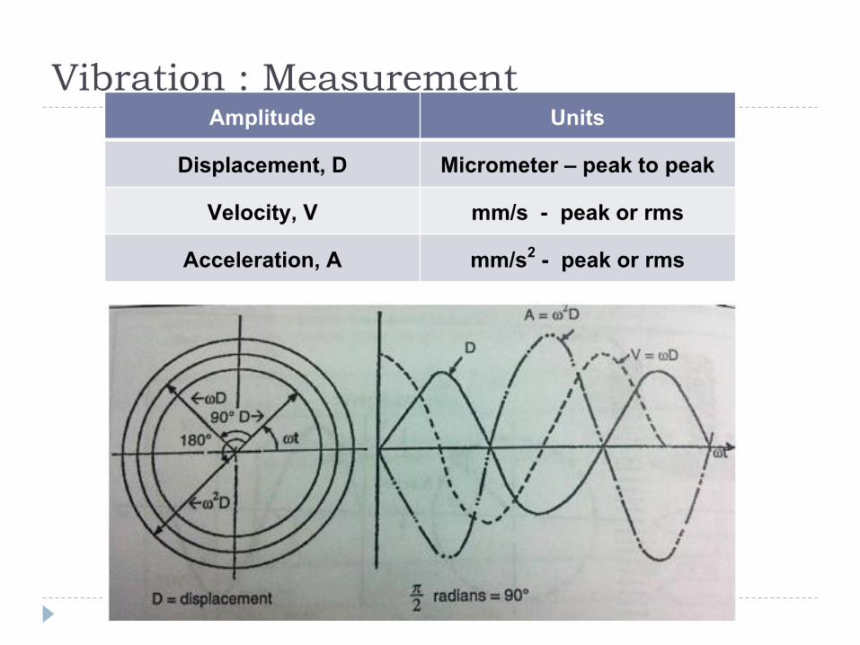
Vibration : Measurement Amplitude Units
Displacement, D Micrometer – peak to peak
Velocity, V mm/s - peak or rms
Acceleration, A mm/s2 - peak or rms

Types of transducer
Proximity Probe Seismic Velocity
Probe Acceleration Probe
Relative displacement Velocity Acceleration
0 – 1,500 Hz 8 – 1,500 Hz 1 – 20,000 Hz

Mounting method
Method Frequency limit (Hz)
Hand held 500 Magnet 2,000
Adhesive 2,500 – 4,000
Bees wax 5,000
Stud 6,000 – 10,000

FFT analysis
Fast fourier
transform (FFT)

Vibration monitoring and analysis
Raw Data
Time domain
Analysis data
Frequency domain
FFT analyzer Sensor

Example Unbalance
Misalignment
Spur gear
Centrifugal pump

Type of unbalance 1. Static unbalance 2. Couple unbalance 3. Dynamic unbalance

12
Static Unbalances
เกดิจากต าแหน่ งทีแ่หก่ ่า้น่กัแหยกตวัจากแหก่ของเพลาใ่ขณะนมุ่ แหละข่า่ก ั่
Corrected
balance weight in one plane at rotor centre of gravity (CG).

Couple Unbalances
เกดิจากต าแหน่ งของแหก่ ่า้น่กัแหยกตวัจากแหก่ของเพลาใ่ขณะนมุ่แหละ ่า้น่กัของการไม สมดลุเท าก ั่ ใ่ทศิทางตรงก ั่ ขา้ม 180 องศา
Corrected
balancerequires correction in two planes at 180°.
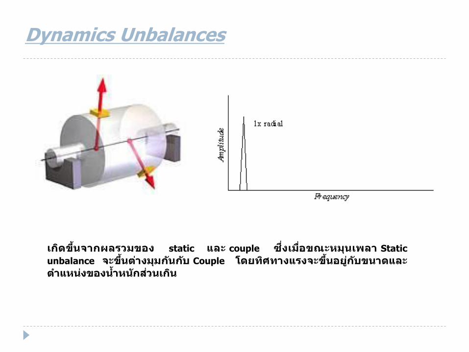
Dynamics Unbalances
เกดิขึ้่ จากผลรวมของ static แหละ couple ซึง่เมือ่ขณะนมุ่เพลา Static
unbalance จะขึ้่ ต างมุมก ั่ กบั Couple โดยทศิทางแหรงจะขึ้่ อยู กบัข่าดแหละต าแหน่ งของ ่า้น่กัส ว่เก ิ่

Special case of Dynamics Unbalances
Corrected
Overhung rotors often have both static and couple unbalance each of which may require correction.
Overhung Rotor Unbalance
ตวัอย่างการท า Balancing ใบพดัลม ของ cooling tower
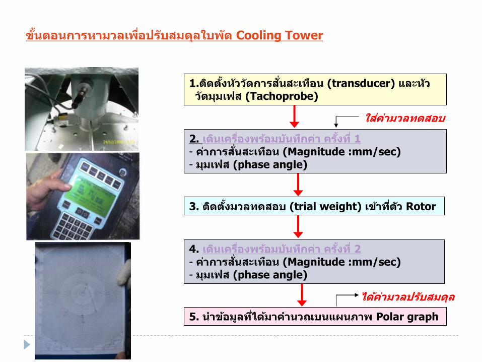
ข ั้่ ตอ่การนามวลเพือ่ปรบัสมดลุใบพดั Cooling Tower
1.ตดิต ัง้นวัวดัการส ั่่ สะเทอื่ (transducer) แหละนวั วดัมมุเฟส (Tachoprobe)
2. เด ิ่ เครือ่งพรอ้มบ ั่ ทกึค า คร ัง้ที ่1 - ค าการส ั่่ สะเทอื่ (Magnitude :mm/sec) - มมุเฟส (phase angle)
3. ตดิต ัง้มวลทดสอบ (trial weight) เขา้ทีต่วั Rotor
4. เด ิ่ เครือ่งพรอ้มบ ั่ ทกึค า คร ัง้ที ่2 - ค าการส ั่่ สะเทอื่ (Magnitude :mm/sec) - มมุเฟส (phase angle)
5. ่าขอ้มลูทีไ่ดม้าค า่วณบ่แหผ่ภาพ Polar graph
ใส ค ามวลทดสอบ
ไดค้ ามวลปรบัสมดลุ
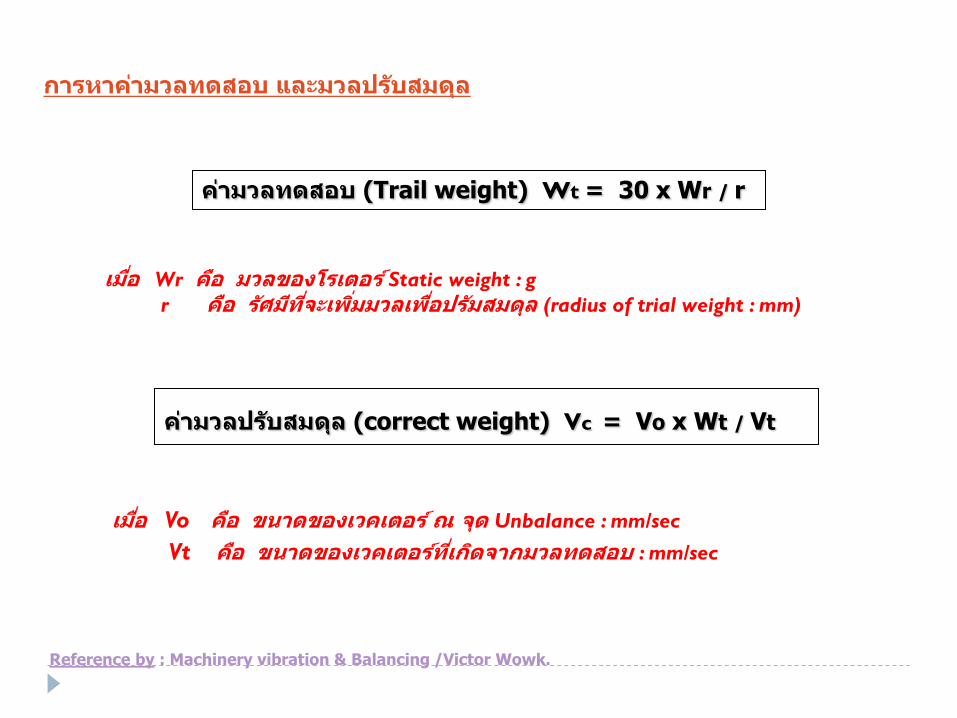
การนาค ามวลทดสอบ แหละมวลปรบัสมดลุ
ค ามวลทดสอบ (Trail weight) Wt = 30 x Wr / r
เมือ่ Wr คอื มวลของโรเตอร ์Static weight : g r คอื รศัมทีีจ่ะเพิม่มวลเพือ่ปรมัสมดลุ (radius of trial weight : mm)
ค ามวลปรบัสมดลุ (correct weight) Vc = Vo x Wt / Vt
เมือ่ Vo คอื ข่าดของเวคเตอร ์ณ จดุ Unbalance : mm/sec
Vt คอื ข่าดของเวคเตอรท์ีเ่กดิจากมวลทดสอบ : mm/sec
Reference by : Machinery vibration & Balancing /Victor Wowk.

จาก spectrum ของ cooling #4 จะพบว าทีค่วามถีข่องตวัใบพดัลม ต าแหน่ ง 1X rpm ่ ั้่ จะพบค า Amplitude ทีเ่กดิจากการส ั่่ สะเทอื่ อ ั่ เ่ือ่งมากจาก Unbalancing
Frequency : 355.3
Amplitude: 4.379
Phase : 84 degree
กราฟสเปกตรมัของชุดมอเตอรเ์กยีรแ์หละใบพดัลม (ก อ่ปรบัสมดลุ)

Vector correct & angle phase on Polar graph
Data: 1.Rotor & Fan weight : 26 kg ,(4x32 kg)
2. Radius of trial : 220 mm.
Vector unbalance Vo: 4.379 mm/sec
Phase Vo: 84 degree.
Trial weight : 25 g (21 g)
Vector unbalance +weight V1: 7.4 mm/sec
Phase V1: 215 degree.
Vector from trial weight Vt: 10.8 mm/sec
Phase : 329 degree. (Vt-Vc)
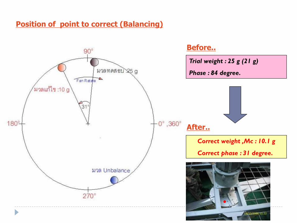
Position of point to correct (Balancing)
Trial weight : 25 g (21 g)
Phase : 84 degree.
Correct weight ,Mc : 10.1 g
Correct phase : 31 degree.
Before..
After..
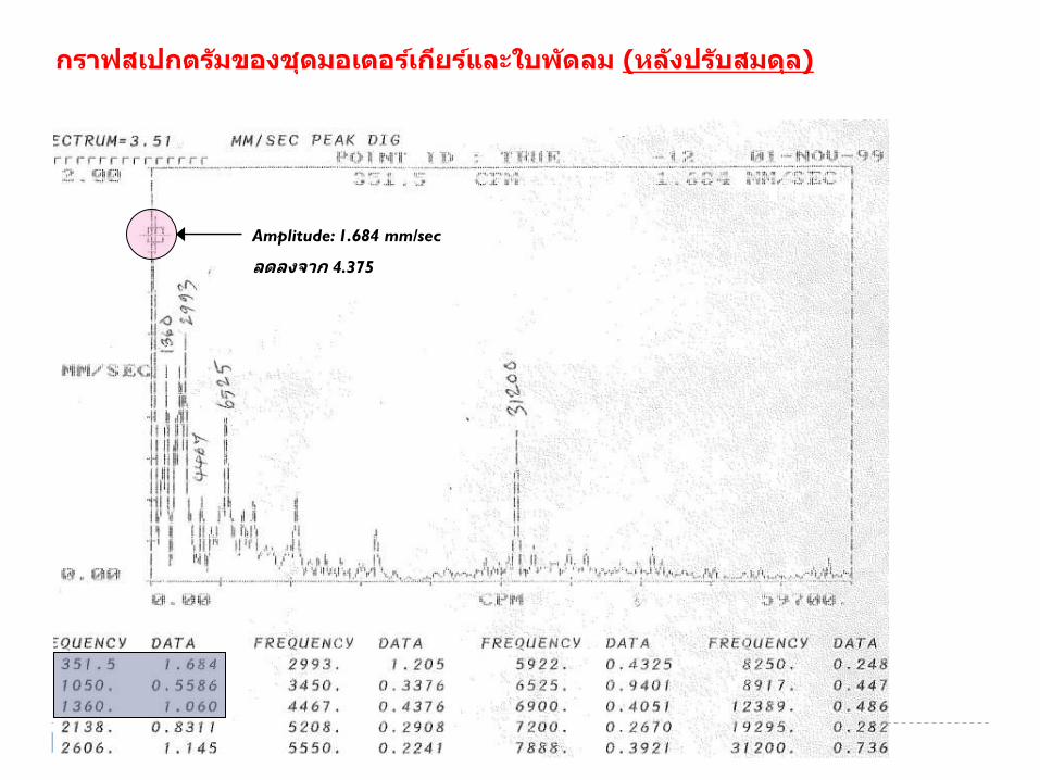
Amplitude: 1.684 mm/sec
ลดลงจาก 4.375
กราฟสเปกตรมัของชุดมอเตอรเ์กยีรแ์หละใบพดัลม (นลงัปรบัสมดลุ)

Misalignment

Misalignment
Introductio
n
What is it ?
Misalignment is a condition
where the centerlines of
coupled shafts do not coincide.

EX.
Introductio
n Misalignment

Introductio
n
Bearing, Coupling, Seal and Shaft failure
Lost time to repair machine
Lost opportunity to run process
Lost Maintenance Cost
Misalignment

Type of
misalignmen
t Misalignment

Detection
method Misalignment

Introductio
n Misalignment

Misalignment Detection
method
Time- Frequency Domain
Fast fourier
transform (FFT)
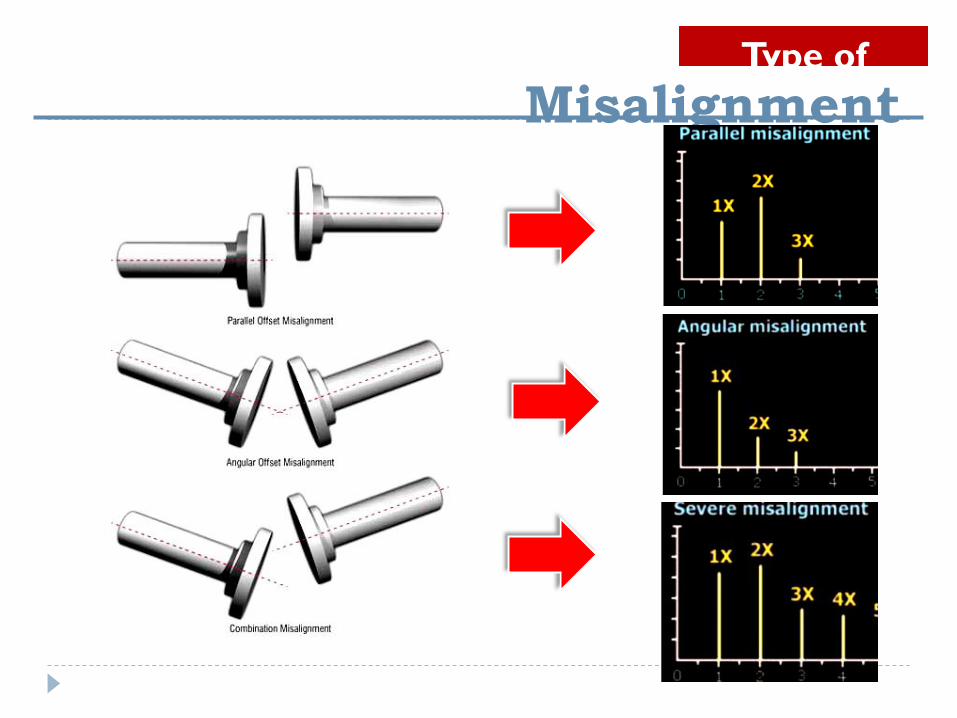
Type of
misalignmen
t Misalignment
Type of
misalignmen
t Misalignment
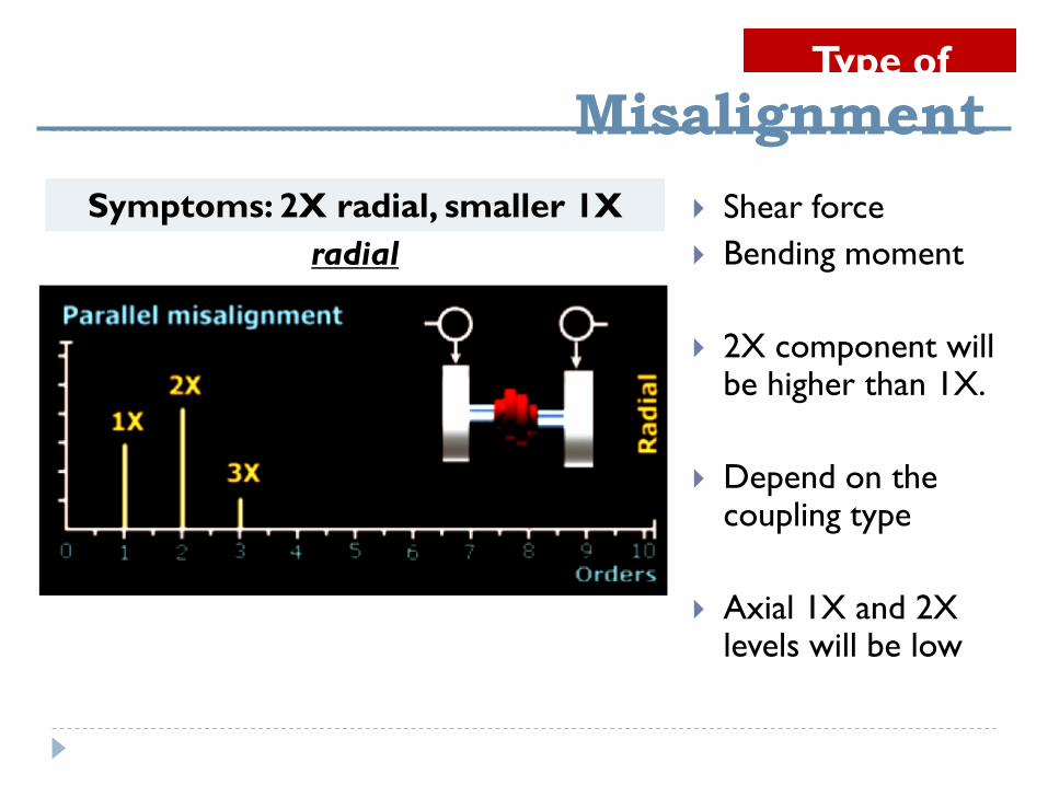
Shear force
Bending moment
2X component will be higher than 1X.
Depend on the coupling type
Axial 1X and 2X levels will be low
Symptoms: 2X radial, smaller 1X
radial

Type of
misalignmen
t Misalignment
Bending moment
Also be fairly
strong radial
1X and 2X levels
Symptoms: High axial vibration: 1X
strong (but 2X and 3X can also be
strong)

Type of
misalignmen
t Misalignment
Can be 3X, 4X all the
way up to 8X peaks
The noise floor is
not raised(unlike
rotating looseness)
Frequency: 1X and 2X (and 3X and
4X…) axial and radial

Spur Gear
Failure Mode : Backlash, Tooth wear and Broken teeth etc.

Normal
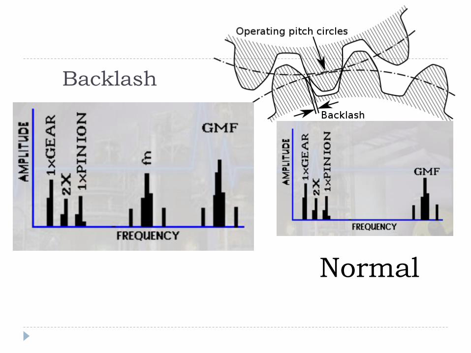
Backlash
Normal

Tooth wear
Normal
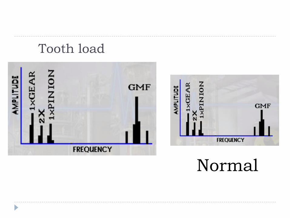
Tooth load
Normal

Broken Tooth
Normal

Broken Tooth
Normal
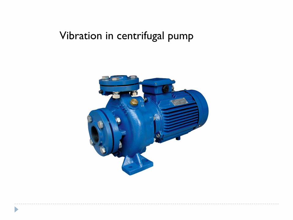
Vibration in centrifugal pump
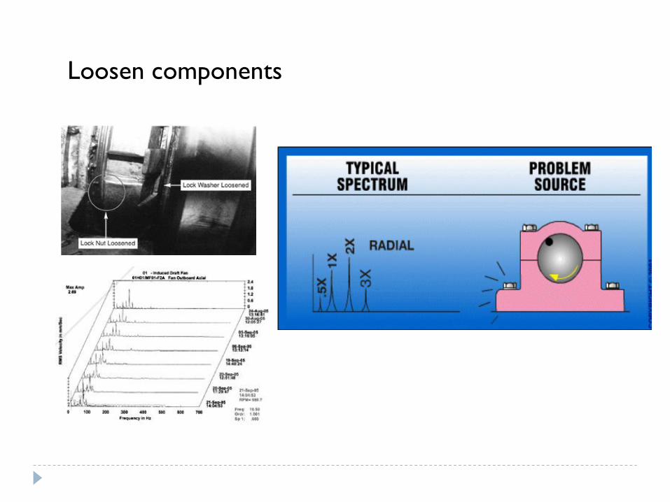
Loosen components

Gap between blade vanes and case is too small
-the BPF will increase

Turbulence flow
-random amplitude
at low frequency

Cavitation
-random amplitude
at high frequency