4 series po 120 install prelim
DESCRIPTION
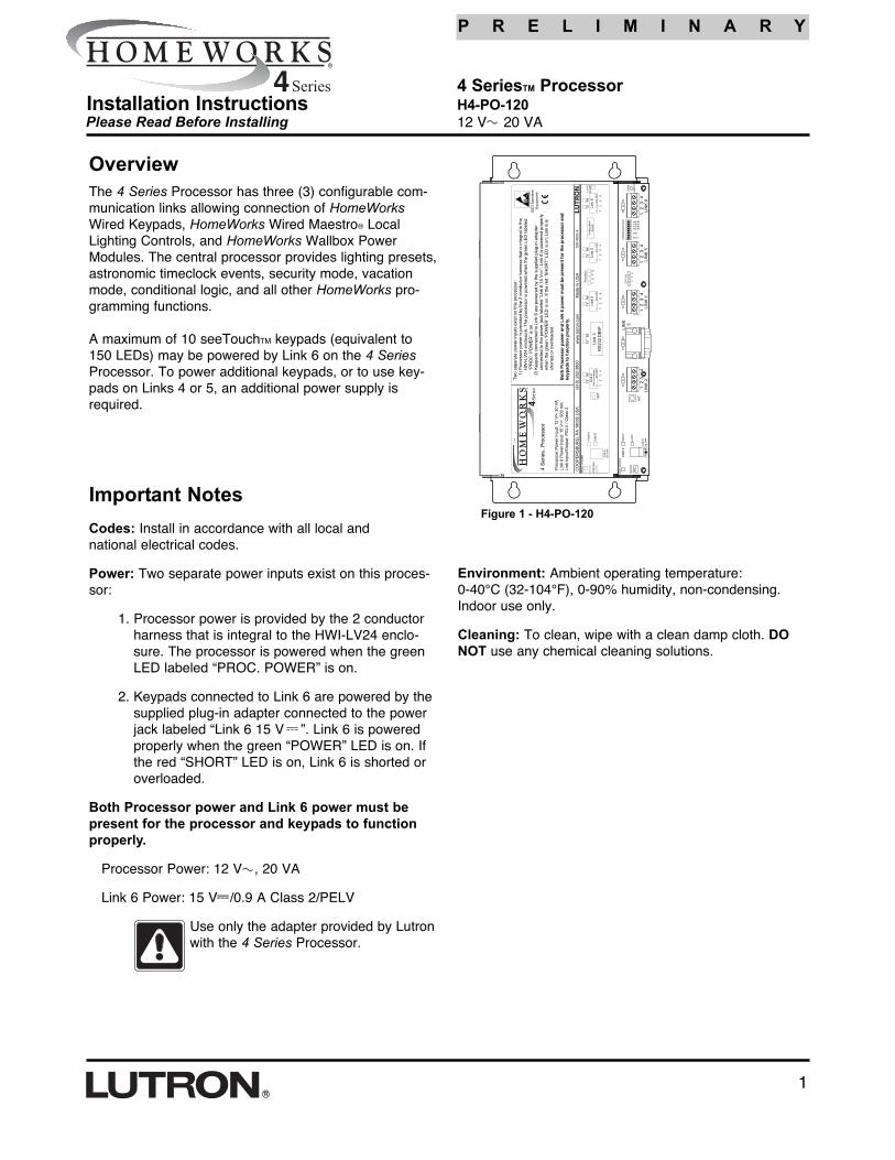
2. Keypads connected to Link 6 are powered by the supplied plug-in adapter connected to the power jack labeled “Link 6 15 V ”. Link 6 is powered properly when the green “POWER” LED is on. If the red “SHORT” LED is on, Link 6 is shorted or overloaded. Both Processor power and Link 6 power must be present for the processor and keypads to function properly. 4 Series TM Processor H4-PO-120 12 V 20 VA Please Read Before Installing Processor Power: 12 V , 20 VA 1 Figure 1 - H4-PO-120TRANSCRIPT
P R E L I M I N A R Y
4 SeriesTM ProcessorH4-PO-12012 V 20 VA
1
Please Read Before InstallingInstallation Instructions
OverviewThe 4 Series Processor has three (3) configurable com-munication links allowing connection of HomeWorksWired Keypads, HomeWorks Wired Maestro® LocalLighting Controls, and HomeWorks Wallbox PowerModules. The central processor provides lighting presets,astronomic timeclock events, security mode, vacationmode, conditional logic, and all other HomeWorks pro-gramming functions.
A maximum of 10 seeTouchTM keypads (equivalent to150 LEDs) may be powered by Link 6 on the 4 SeriesProcessor. To power additional keypads, or to use key-pads on Links 4 or 5, an additional power supply isrequired.
Important NotesCodes: Install in accordance with all local and national electrical codes.
Power: Two separate power inputs exist on this proces-sor:
1. Processor power is provided by the 2 conductorharness that is integral to the HWI-LV24 enclo-sure. The processor is powered when the greenLED labeled “PROC. POWER” is on.
2. Keypads connected to Link 6 are powered by thesupplied plug-in adapter connected to the powerjack labeled “Link 6 15 V ”. Link 6 is poweredproperly when the green “POWER” LED is on. Ifthe red “SHORT” LED is on, Link 6 is shorted oroverloaded.
Both Processor power and Link 6 power must bepresent for the processor and keypads to functionproperly.
Processor Power: 12 V , 20 VA
Link 6 Power: 15 V /0.9 A Class 2/PELV
Use only the adapter provided by Lutronwith the 4 Series Processor.
Figure 1 - H4-PO-120
Environment: Ambient operating temperature: 0-40°C (32-104°F), 0-90% humidity, non-condensing.Indoor use only.
Cleaning: To clean, wipe with a clean damp cloth. DONOT use any chemical cleaning solutions.

2
P R E L I M I N A R Y
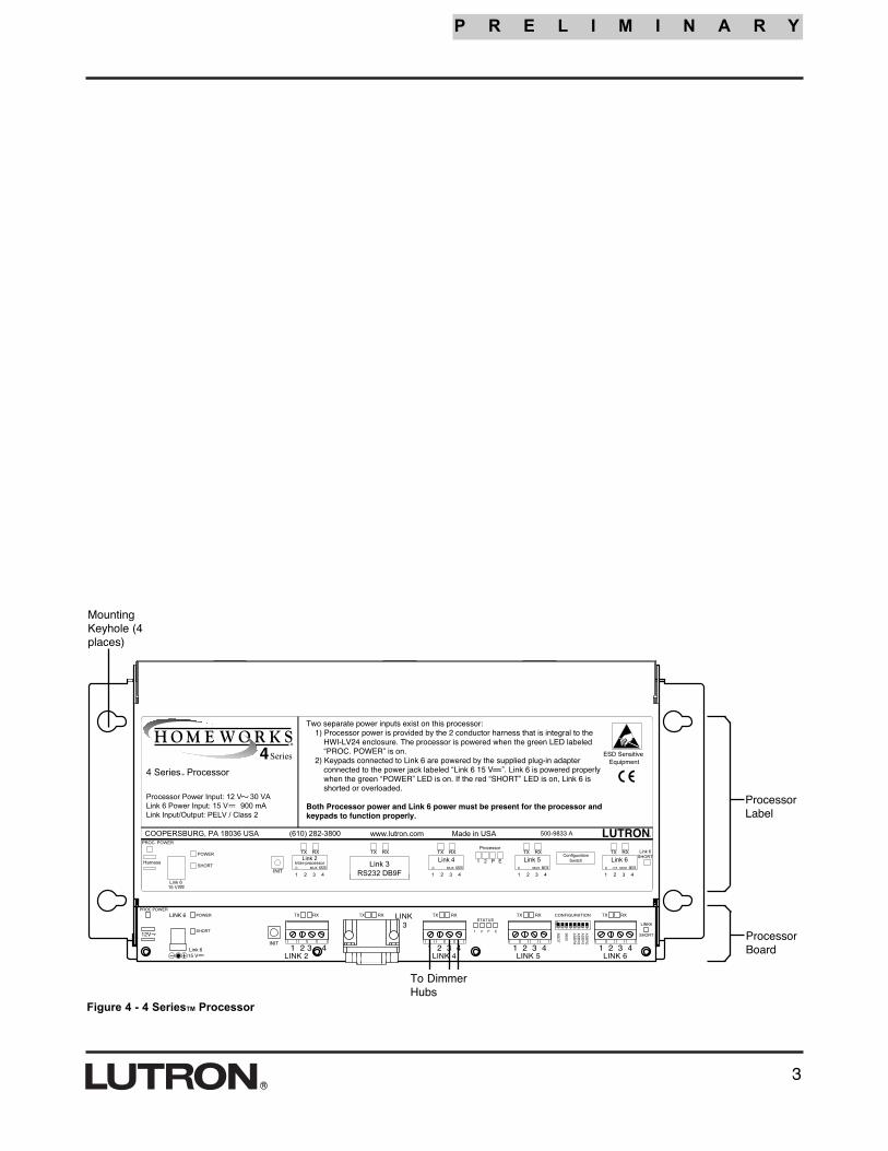
Installation 4. Connect Dimmer Hub links: If HWI-H48 boards are tobe controlled by this processor, the communication link tothose boards should be connected to the Link 4 terminalblock. Do not connect terminal 2 to an HWI-H48. If theH48 Link has a cable length of 50 ft. (15 m) or more, LT-1 link terminators must be installed across MUX andMUX (terminals 3 and 4) at both ends of the link. Refer toHWI-H48 instructions (see Figure 5, page 4).
Note - Links 4, 5 and 6 are configurable for use asKeypad Links, GRAFIK Eye® Links, or H48 Links. Theselinks are configured by the HomeWorks Utility.
5. Connect Inter-processor Link (multiple processorinstallations only): The Inter-processor Link is used forcommunication between HomeWorks Processors.Connect control wiring to the Inter-processor Link (Link2), if required. Do not connect terminal 2 (see Figure 5,page 4). If this processor is to be the first or last proces-sor in the daisy chain, attach one of the LT-1 link termi-nators provided across the MUX and MUX (terminals 3and 4—see Figure 5, page 3). If LT-1 terminators areunavailable, a 1/2 W resistor between 100 and 150Ohms may be placed across terminals 3 and 4 to providetermination.
6. Connect GRAFIK Eye / WPM links: If GRAFIK Eye pre-set dimming controls or Wallbox Power Modules are tobe controlled by this processor, connect the communica-tion wires to Link(s) 4, 5, or 6 as configured in theHomeWorks Utility. Do not connect terminal 2.
7. Connect Keypad links: For keypads or keypad linkdevices (e.g. HWI-CCO-8) that are to be controlled bythis Processor, connect the communication wires toLink(s) 4, 5, or 6 as configured in the HomeWorks Utility.Note: Connecting keypads or keypad link devices to linksother than Link 6 requires an additional power supply.
8. Connect power. Plug the power input harness terminals(blue wires) from the HWI-LV24 enclosure onto thepower feed lugs on the 4 Series Processor. Connect plugfrom adapter to Link 6 Power connector. Plug adapterinto receptacle in bottom of HWI-LV24. The 4 SeriesProcessor has battery-backed memory and timeclockdevices. The battery provides power to these devicesduring power outages and other temporary power inter-ruptions. In vacation homes and other residences whichare not continuously occupied, the 4 Series processorMUST be powered by a circuit that is never turned offeven when the residence is unoccupied.
9. Turn power ON. Restore the supply breaker to the ONposition.
10. Connect Serial Link. Connect a standard DB9 maleconnector to the Link 3 RS232 connector on the proces-sor for system programming or communications withother equipment. A standard serial cable (not a nullmodem) is required for programming the system using alaptop. If, at a later date, the processor is connected to amodem, a null modem adapter will be needed betweenthe processor and the attached modem.
1. Ensure Mains-voltage cover in HWI-LV24 enclosure issecurely installed. Locate and lock supply breaker in theOFF position before installing processor assembly.
Danger - Wiring with power on may result inpersonal injury.
2. Install processor assembly in the enclosure: TheHomeWorks® 4 SeriesTM Processor is attached to the HWI-LV24 enclosure using four mounting keyholes andthe mounting screws provided.
3. Set processor address. Set processor address usingConfiguration Switch. The HomeWorks Utility will promptthe programmer if any subsequent changes to the config-uration switches are required.
Figure 2 - MountingDiagram
The 4 Series Processor mountsin the upper left corner of anHWI-LV24 enclosure.
Mains-voltage enclosure(shown with cover installed).
Figure 3 - Processor Addressing
DIP Switch Function
1 Boot Mode. Unless prompted by theHomeWorks Utility, this switch should alwaysbe in the DOWN position.
2 Diagnostic. This switch should always be inthe DOWN position.
3 UP = 9600 Baud, DOWN = Auto Bauddetect.
4 Battery disconnect. This switch shouldalways be in the DOWN position.
5-8 Processor Address. See Figure 3, below.
Table 2 - Configuration Switch Functions
UP (ON)DOWN (OFF)
Example: Setting Switch #7 ON.
3
P R E L I M I N A R Y
MountingKeyhole (4places)
ProcessorLabel
ProcessorBoard
Figure 4 - 4 SeriesTM Processor
To DimmerHubs

P R E L I M I N A R Y
Lutron Electronics Co., Inc. 7200 Suter RoadCoopersburg, PA 18036-1299Made and printed in the U.S.A. 11/03 P/N 043-xxx Rev. A (pending)
Technical and Sales AssistanceIf you need assistance, call the toll-free LutronTechnical Support Center. Please provide exactmodel number when calling.(800) 523-9466 (U.S.A., Canada and the Caribbean)Other countries call:Tel: (610) 282-3800Fax: (610) 282-3090Visit our Web site at www.lutron.com
LIMITED WARRANTYLutron will, at its option, repair or replace any unit that is defective in materials or manufac-ture within two years after purchase. For warranty service, return unit to place of purchase ormail to Lutron at 7200 Suter Rd., Coopersburg, PA 18036-1299, postage pre-paid. Telephonethe Lutron Technical Support Center toll free at 800-523-9466. After the two year period, apro-rated warranty applies to this product until eight years after the purchase. For more infor-mation regarding this warranty contact your Lutron representative.THIS WARRANTY IS IN LIEU OF ALL OTHER EXPRESS WARRANTIES, AND THEIMPLIED WARRANTY OF MERCHANTABILITY IS LIMITED TO TWO YEARS FROM PUR-CHASE. THIS WARRANTY DOES NOT COVER THE COST OF INSTALLATION,REMOVAL OR REINSTALLATION, OR DAMAGE RESULTING FROM MISUSE, ABUSE,OR IMPROPER OR INCORRECT REPAIR, OR DAMAGE FROM IMPROPER WIRING ORINSTALLATION. THIS WARRANTY DOES NOT COVER INCIDENTAL OR CONSEQUEN-TIAL DAMAGES. LUTRON’S LIABILITY ON ANY CLAIM FOR DAMAGES ARISING OUTOF OR IN CONNECTION WITH THE MANUFACTURE, SALE, INSTALLATION, DELIVERY,OR USE OF THE UNIT SHALL NEVER EXCEED THE PURCHASE PRICE OF THE UNIT.This warranty gives you specific legal rights, and you may also have other rights which varyfrom state to state. Some states do not allow limitations on how long an implied warranty lasts,so the above limitation may not apply to you. Some states do not allow the exclusion or limi-tation of incidental or consequential damages, so the above limitation or exclusion may notapply to you.Lutron, HomeWorks, Maestro, and GRAFIK Eye are registered trademarks and 4 Series,seeTouch, and the HomeWorks 4 Series logo are trademarks of Lutron Electronics Co., Inc.© 2003 Lutron Electronics Co., Inc.
1
2 3
4
LT-1 LinkTerminator
LT-1 LinkTerminatorWiring Detail
LT-1 LinkTerminator
LT-1 LinkTerminator
Wiring Detail
4 SeriesTM
Processor
Pin 1 - 1 18 AWG (1.0 mm2)Pins 3 & 4 - 1 pair 22-18 AWG (0.5 - 1.0 mm2)
twisted/shielded for dataPin 2 is not connected
1000 ft. (305 m) maximum total wire run distance
8 SeriesTM
Processor
Figure 5 - Daisy Chained HomeWorks® Processors
RF Processor