4. turbine - engsoft.co.kr · sometimes, combustion products contain corrosive compounds. the...
TRANSCRIPT

Combined Cycle Power Plants 4. Turbine 1 / 119
HIoPE
4. Turbine

Combined Cycle Power Plants 4. Turbine 2 / 119
HIoPE
Impulse and Reaction Turbines 48 4
Introduction 2 1
Dimensionless Numbers 30 3
Thermodynamics and Fluid Dynamics for Turbines 12 2
Advanced Vortex Blades 81 6
Blade Materials 90 7
Stage Efficiency 76 5
Contents
Blade Cooling 101 8

Combined Cycle Power Plants 4. Turbine 3 / 119
HIoPE
Air inlet Compressor Combustors
Turbine
Exhaust
Cold section Hot section
The function of the turbine is to extract energy from the working fluid and convert it to
mechanical energy, thereby enabling the turbine to drive the compressor and generator.
Turbine

Combined Cycle Power Plants 4. Turbine 4 / 119
HIoPE
The turbine has the task of providing power to drive the compressor and generator.
It does this by extracting energy from the hot gases released from the combustion system and expanding
them to a lower pressure and temperature.
The design of the nozzle and turbine bucket is broadly based on aerodynamic considerations, and to obtain
optimum efficiency, compatible with compressor and combustor design.
The desire to produce a high engine efficiency demands a high turbine inlet temperature, but this causes
problems as the turbine blades would be required to perform and survive long operating periods at
temperatures above their melting point.
These blades, while glowing red-hot, must be strong enough to carry the centrifugal loads due to rotation at
high speed.
Therefore, turbine blade material should have excellent creep characteristics and should be cooled
effectively.
Nickel alloys are used to construct the turbine blades and the nozzle guide vanes because these materials
demonstrate good properties at high temperatures.
Generals for Turbines

Combined Cycle Power Plants 4. Turbine 5 / 119
HIoPE
Compressor vs. Turbine
Turbines are easier to design because large pressure drop can be achieved per stage without the danger of
flow separation. Therefore, the permissible work extracted per stage within the turbine is much greater than
that correspondingly put in the compressor. This is because the accelerating flow within the turbine is much
more tolerant to flow separation than the diffusing flow in compressors.
Therefore, fewer stages are required in operating turbines as compared to compressors to achieve the same
change in pressure.
Therefore, much higher efficiencies can be achieved in the turbine stages.
However, the turbine has other problems that are not present in compressors. For example, the presence of
high-temperature gases causes reduced life expectancy and requires the materials having good creep
characteristics. In addition, the presence of particle in combustion products results in erosion problems.
Sometimes, combustion products contain corrosive compounds.
The analysis of a turbine is very similar to that of a compressor stage. Many of equations and physics
developed are common to both, with the exception of major differences in the property changes listed below.
1) In a turbine the parameter po, ho, and To decrease through the bucket, while they increase across a
compressor rotor.
2) The compressor operates at lower temperatures than a turbine.
3) The flow turning is much higher (50-180) in a turbine than in a compressor (20-35).
4) The blade thickness and profiles differ considerably.
5) The annulus area increases in a multistage turbines and decreases in a multistage compressor.
6) Material considerations (high temperature and stress) are much more critical in a turbine.

Combined Cycle Power Plants 4. Turbine 6 / 119
HIoPE
Configuration

Combined Cycle Power Plants 4. Turbine 7 / 119
HIoPE
Nozzle Bucket
The turbine is composed of several rows of airfoil cascades to produce the
driving torque.
Buckets are connected to the central shaft and rotate at high speed. Nozzles
are fixed and do not rotate.
To avoid blade vibration difficulties, the axial gap between nozzle and bucket
should be approximately 0.25 times the upstream axial chord.
Turbine Blade
Combined Cycle Power Plants 4. Turbine 8 / 119
HIoPE
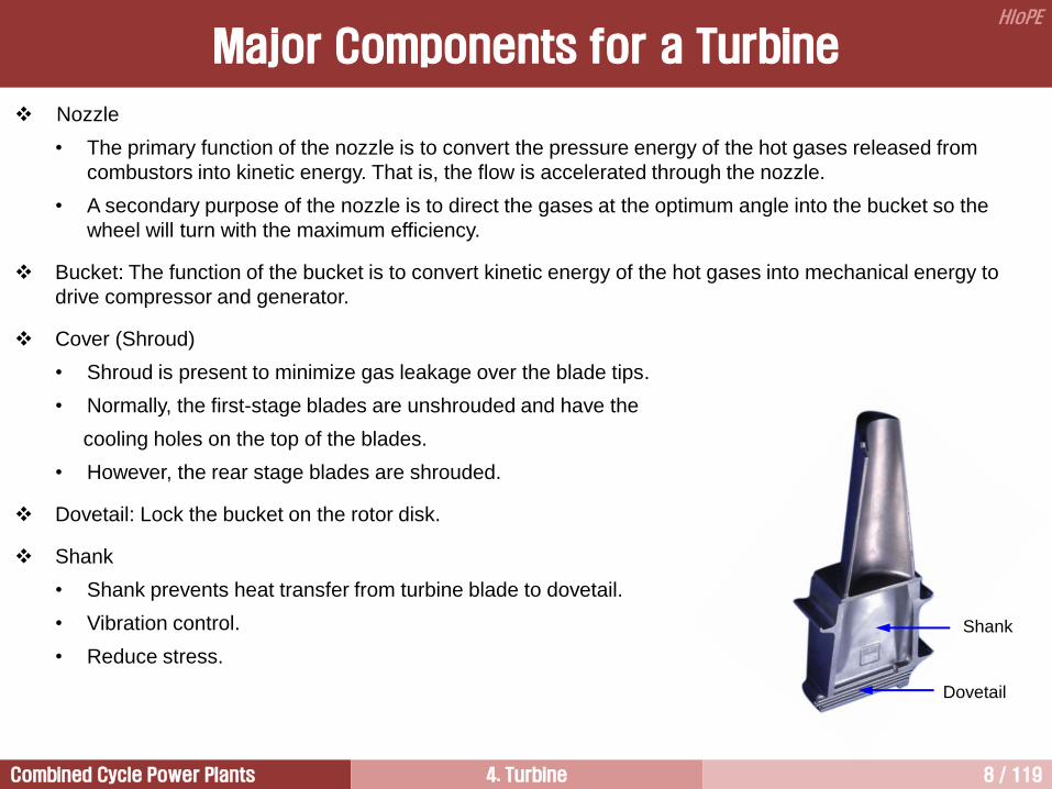
Nozzle
• The primary function of the nozzle is to convert the pressure energy of the hot gases released from
combustors into kinetic energy. That is, the flow is accelerated through the nozzle.
• A secondary purpose of the nozzle is to direct the gases at the optimum angle into the bucket so the
wheel will turn with the maximum efficiency.
Bucket: The function of the bucket is to convert kinetic energy of the hot gases into mechanical energy to
drive compressor and generator.
Cover (Shroud)
• Shroud is present to minimize gas leakage over the blade tips.
• Normally, the first-stage blades are unshrouded and have the
cooling holes on the top of the blades.
• However, the rear stage blades are shrouded.
Dovetail: Lock the bucket on the rotor disk.
Shank
• Shank prevents heat transfer from turbine blade to dovetail.
• Vibration control.
• Reduce stress.
Major Components for a Turbine
Dovetail
Shank

Combined Cycle Power Plants 4. Turbine 9 / 119
HIoPE
[ Shrouded blade ] [ Free tip blade ]
Shrouded Blade
Shrouded blades have reduced leakage losses because they have seal system at the blade tip.
Shrouded blades have better vibration characteristics because they are often interlocked to provide
mechanical damping.
Shrouded blades give better efficiency because they have better aerodynamic characteristics at the blade tip.
The tip vortex formed from open tip blade produce a large disturbed flow when it combined with secondary
flow in the blade passage.
However, the shroud creates increased stress levels.
[ Tip vortex ]

Combined Cycle Power Plants 4. Turbine 10 / 119
HIoPE
Tip Leakage Loss

Combined Cycle Power Plants 4. Turbine 11 / 119
HIoPE
Wing Let

Combined Cycle Power Plants 4. Turbine 12 / 119
HIoPE
Impulse and Reaction Turbines 4
Introduction 1
Dimensionless Numbers 3
Thermodynamics and Fluid Dynamics for Turbines 2
Advanced Vortex Blades 6
Stage Efficiency 5
Blade Materials 7
Blade Cooling 8

Combined Cycle Power Plants 4. Turbine 13 / 119
HIoPE
Heat and Work in a Gas Turbine
754 MJ/s
(100%)
205 MW
(27.2%)
203 160 119 MW = 482 MW (63.9%)
277 MW (net output)
(36.7%)
272 MJ/s
(36.1%)
Q1. 터빈 각 단의 출력을 이 그림에 나타나 있는 것처럼 앞 단에서는 크게 하고 뒷 단에서는 작게 하려면 터빈 단 설계에 있어서 일차적으로 고려해야 할 요소가 무엇인가?
Q2. 터빈 앞 단에서 뒷 단보다 많은 출력을 발생시키면 가스터빈 가격 측면에서 어떤 장점을 가지는가?

Combined Cycle Power Plants 4. Turbine 14 / 119
HIoPE
Most axial-flow turbines consist of more than one stage; the front stages are
usually impulse and the later stages are 50% reaction.
Because the temperature drop is higher for low/zero-reaction turbines, the
nozzle of subsequent stages have lower temperatures and thus require less
cooling air.
The impulse stages produce about twice the output of a reaction stage,
whereas the efficiency of an impulse stage is less than that of a reaction
stage. This is because all the flow acceleration occurs within a nozzle
passage, and this increases losses.
The final stage exit Mach number should be around 0.3. the highest
allowable is 0.55.
The final stage turbine exit swirl angle should be less than 20, and ideally 5
on the pitch line to minimize downstream duct pressure loss.
The hade angle is normally kept to less than 15 to avoid flow separation.
Flow Characteristics

Combined Cycle Power Plants 4. Turbine 15 / 119
HIoPE
4,3, oopT TTc
1
3,
4,
3,
3,
4,
3, 11o
o
opT
o
o
opTp
pTc
T
TTc
1
3, 1 TPRTc opT
1
3,
4,
3,
4,
o
o
o
o
T
T
p
pTPR
T
p
o
o
o
C
h
T
p
= total pressure
= total temperature
= specific stagnation enthalpy
= specific heat
= specific heat ratio
= isentropic efficiency of compressor
Turbine Thermodynamics
4,3, ooT hhTW
h
s
1
2
3
4
3
4
2
Compressor
Fuel Combustor
Turbine
Air
Power
Exhaust gas 1
2 4 3

Combined Cycle Power Plants 4. Turbine 16 / 119
HIoPE
High temperature and pressure gas enters the first stage nozzle axially at less than Mach number of 0.2 and
is then accelerated across the nozzle which reduces flow area. The mean nozzle exit Mach number may be
around 0.8. And the nozzle exit angle will be between 65 and 73.
There is no work or heat transfer, and only a small loss in total pressure due to friction and turbulence
losses. Total temperature remains unchanged, except by addition of cooling air, while static pressure and
temperature reduce due to the flow acceleration.
Power is extracted across the bucket via the change in tangential velocity. As the flow passes through the
bucket, the total pressure and temperature decrease.
The decrease in pressure is measured by the turbine pressure ratio (TPR), which is the ratio of the air
pressure exiting the turbine to the air pressure entering the turbine. This number is always less than 1.0.
Since no external heat is being added to or extracted from the turbine during this process, the process is
adiabatic (isentropic).
Work is done by the flow to turn the turbine and the shaft.
From the conservation of energy, the turbine work per mass of airflow (TW) is equal to the change in the
specific enthalpy of the flow from the entrance to the exit of the turbine. (The term “specific” means per mass
of airflow.) The enthalpy at the entrance and exit is related to the total temperature at those stations.
The work done by the turbine is related to the turbine pressure ratio, the incoming total temperature, some
properties of the gas, such as specific heats (cp) and specific heat ratio (), and an efficiency factor (T).
The efficiency factor is included to account for the actual performance of the turbine as opposed to the ideal,
isentropic performance.
Turbine Thermodynamics

Combined Cycle Power Plants 4. Turbine 17 / 119
HIoPE
Flow Behavior in a Turbine Stage
Pressure E Kinetic E
Thermal E Thermal E Mechanical E
Nozzle row Bucket row
z
r
The flow behavior is investigated in a tangential plane.
Therefore, the flow velocity has two components, one is axial
component denoted by subscript z, and the other is
tangential component denoted by subscript implying a whirl
velocity.

Combined Cycle Power Plants 4. Turbine 18 / 119
HIoPE
Velocity Triangles in Axial Flow Compressors [2/4]
Most axial flow turbines are designed on the basis of
constant axial velocity throughout the stages because
of the simplifications of design procedure of the
subsequent stage.
c : absolute velocity
w : relative velocity
u : tangential velocity
of blade
Fluid velocity is an important variable governing the
flow and energy transfer within a turbine.
The absolute velocity ( ) is the fluid velocity relative
to some stationary point and is usually parallel to the
nozzle (stationary blade).
When considering the flow across a rotating element
like a bucket, the relative velocity ( ) is important and
is usually parallel to the rotating element.
Vectorially, the relative velocity is defined as:
where is the tangential velocity
of the bucket.
ucw
u
w
c
u
u
c2
w2
2
2
w3
3 c3
p1
p2
p3
u
1
c1
3
Nozzle Row
Bucket Row

Combined Cycle Power Plants 4. Turbine 19 / 119
HIoPE
Velocity Triangle in a Turbine
Velocity Triangle at Root
Root
Tip
rRoot rTip
Nozzle row Bucket row
c : absolute velocity of fluid
u : tangential velocity of blade
w : velocity of fluid relative to blade
u
u
c2
w2
2
2
w3
3 c3
p1
p2
p3
u
1
c1
3
Nozzle row
Bucket row
The absolute velocity increases from c1 to c2 across the nozzle.
The absolute velocity decreases from c2 to c3 across the bucket. This is because the kinetic energy entering
bucket is extracted by the bucket. Thus, bucket attains rotating power.
In the case of turbine, the convention chosen is that the angles are positive when measured in the direction
of rotation. Therefore, 2, 2 are positive; 3, 3 are negative.

Combined Cycle Power Plants 4. Turbine 20 / 119
HIoPE
Velocity Triangle at Tip
Velocity Triangle in a Turbine
Root
Tip
rRoot rTip
Nozzle row Bucket row
u
u
c2
w2
w3
p1
p2
p3
u
1
c1
Nozzle row
Bucket row
2
2
3 c3
3

Combined Cycle Power Plants 4. Turbine 21 / 119
HIoPE
A nozzle is used to provide partial
expansion of the gas as well as to
guide the flow smoothly into a
bucket.
If the flow is isentropic in the
nozzle, condition 2s is achieved
after passing through the nozzle.
Practically, however, nozzle
expansion occurs along curve 1-2
because of losses occurred in the
nozzle path.
Change in stagnation pressure
(po,1po,2) is due to the losses,
because there is no work
extraction from the fluid inside the
nozzles.
The process along 2-3 represents
the expansion through bucket.
If the flow is isentropic only in the
bucket, condition o,3s or 3s is
achieved.
Expansion Lines
u
u
c2
w2
2
2
w3
3
c3
p1
p2
p3
u
1
c1
3
Nozzle row
Bucket row
[ Expansion line in a turbine stage ]
p3
po3
1
o,3ss
1/2c12
p2
o,1
p1
po,2 po,1
1/2c12
2
1/2c22
h
s
1/2c32
3ss
2s
o,3s
3s
o,3
3
o,2

Combined Cycle Power Plants 4. Turbine 22 / 119
HIoPE
Turbine Efficiencies
Total-to-static Efficiency Total-to-total Efficiency
• In many turbines (especially steam turbines), the
kinetic energy at the exit (c32/2) should be as small
as possible, because this represents aerodynamic
loss.
• Therefore, the design philosophy is to achieve as
low a velocity at the exit as possible. For this reason,
active length of LSB of steam turbines is very long.
• In such situations, a total-to-static efficiency is used.
• In most aeronautical applications gas turbines, the
exhaust energy is utilized for thrust generation.
Therefore, the exhaust energy is used to produce
useful power.
• Therefore, a more appropriate definition to
represent the performance of these turbines is the
total-to-total efficiency .
• The total-to-total efficiency is also defined as
isentropic efficiency.
• For a multistage turbine, total-to-total efficiency
should be used because the kinetic energy at the
exit of a stage (except the last stage) is not lost.
sso
oo
ssssossoo
oo
tshh
hh
hhhh
hh
31,
3,1,
33,3,1,
3,1,
ssoo
oo
tthh
hh
3,1,
3,1,

Combined Cycle Power Plants 4. Turbine 23 / 119
HIoPE
Notation for Flow in a Bucket Row
r2 r3
w2 or c2 w3 or c3
Bucket
row
u
u
c2
w2
2
2
w3
3 c3
p1
p2
p3
u
1
c1
3
Nozzle row
Bucket row
u
w3
3
c3
c2
w2
2 2
3
N B
w,3
c,2 c,3
w,2
dc = (c,2 c,3)
u
c: absolute velocities (velocities in the reference
frame of the nozzles)
w: relative velocities (velocities relative to moving
surface, the buckets)
u: tangential velocities of blades (in the positive
direction)
2, 2 are positive, and 3, 3 are negative.

Combined Cycle Power Plants 4. Turbine 24 / 119
HIoPE
Euler Equation [1/6]
The change of momentum between the flow entering and leaving the bucket can be used to calculate the
force acting on the bucket.
There are three principal components of this force, axial, radial, and tangential.
The axial and radial components are important for the design of bearings and for the analysis of vibration
excitations, etc.
But, these two components cannot contribute to the work transfer between the working fluid and the bucket.
Only the tangential component of the force can produce a change in enthalpy through a work transfer.
Tangential force on rotor from entering fluid =
Work bucket = force length =
Power on bucket per unit time = work on rotor / time =
Net power on bucket,
Therefore, Euler’s equation can be derived.
(e.1)
Turbine has a positive work out, however, a pump, fan, and compressor will have negative work out.
2,cm
22, rcm
22, rcm
3,32,233,22,23 cucumrcrcmW
3,32,22323 / cucumWw
22, cc
Euler equation

Combined Cycle Power Plants 4. Turbine 25 / 119
HIoPE
Euler Equation [2/6]
For an adiabatic bucket row in the absence of external torques, or large changes in elevation, the first law of
thermodynamics gives,
(e.3)
The first law of thermodynamics is,
(e.2)
3,2,23 oob hhww
2323
2
2
2
3223323232
1wzzgccppuuq
2323
2
2
2
323232
1wzzgcchhq
23232,3,23 wzzghhq oo
232,3,23 whhq oo
Therefore, following relationship can be obtained from Euler equation,
or (e.4)
It is clear that the stagnation enthalpy and pressure drop in a turbine are directly proportional to the change
in tangential velocity and blade speed. This is the most useful single relation in compressor/turbine design.
In the preliminary design of axial flow machines, the change of radius of the mean flow can often be ignored,
so that a more restricted version of Euler’s equation becomes
(e.5)
θucddho
θdcudho
c2
c3 q
w z2
z3
2
3
3,32,23,2,23 cucuhhww oob

Combined Cycle Power Plants 4. Turbine 26 / 119
HIoPE
Pressure and Temperature Drop in a Bucket Row
Euler Equation [3/6]
2,23,32,3,2,3, cucuTTchh oopoo
11
1
2,
3,
2,
2,
3,
2,2,3,
o
o
op
o
o
opoop
pTc
T
TTchh
32222,3,2,23,3 tantancos ucccucucu
1
32
2,
22
2,
3,tantan
cos1
opo
o
Tc
uc
p
p
For simple diagram having constant u from stage inlet to outlet,
32
2,
22
2,
3,tantan
cos1
opo
o
Tc
uc
T
T
2,23,32,3,23 cucuhhww oob
1
322
2,
3,tantan
11
a
uv
p
pz
o
o
322
2,
3,tantan
11
a
uv
T
Tz
o
o

Combined Cycle Power Plants 4. Turbine 27 / 119
HIoPE
1
322
2,
3,tantan
11
a
uv
p
pz
o
o
322
2,
3,tantan
11
a
uv
T
Tz
o
o
The pressure drop and temperature drop in a turbine are strongly dependent on the blade speed, axial
velocity or mass flow, inlet and exit flow angles, and absolute (23) or relative flow turning angles (23).
Higher turning angles produce larger pressure and temperature drops, and thus a higher work output.
Unlike compressors, large flow turning can be accomplished without flow separation.
The effect of the mass flow (or flow coefficient) is opposite to that of a compressor. A turbine with 2 and 3
fixed and blade speed held constant, higher mass flow produces larger pressure and temperature drops.
If 2, 3, and mass flow held constant, higher blade speeds produce larger pressure or temperature drops
and higher work output per stage.
Therefore, higher speeds result in more compact power plants. (this is why aerospace gas turbines operate
at highest possible speed allowed by stress limits)
Pressure and Temperature Drop in a Bucket Row
Euler Equation [4/6]

Combined Cycle Power Plants 4. Turbine 28 / 119
HIoPE
[ Exercise 3.1 ] Use of the Euler’s equation
What is the power output (kW) of the first stage of an axial flow turbine which takes 600 kg/s of gas at
1550C and 20 bar stagnation conditions? After passing through the nozzle, the flow leaves nozzle at a
direction 70 degrees from that of axial, at a velocity of 680 m/s, as given in figure, and discharges it from
the bucket (rotor) without swirl (c,2 = 0). The pitch diameter of the bucket is 1 m, and the shaft speed is
3600 rpm. The turbine has an isentropic stagnation-to-stagnation stage efficiency of 90 percent.
Euler Equation [5/6]
2=70

Combined Cycle Power Plants 4. Turbine 29 / 119
HIoPE
[Solution]
Power output of the stage can be obtained
The first law of thermodynamics is as follows,
The turbine can be treated as adiabatic. Therefore,
From the Euler equation,
From the given conditions,
Therefore,
2,23,32,23,2, cucucuhh oo
smrn
u /5.18860
22
smcc /639sin 222,
23,2, /452,120 smhh oo
kWs
m
s
kghhmhmW oo 271,72120452600
2
2
3,2,23
MWWW turbinenet 6523,23
Euler Equation [6/6]
232,3,23 whhq oo
2,3,23 oo hhw 3,2,23 oo hhmW
3,2,23 oo hhmhmW

Combined Cycle Power Plants 4. Turbine 30 / 119
HIoPE
Impulse and Reaction Turbines 4
Introduction 1
Dimensionless Numbers 3
Thermodynamics and Fluid Dynamics for Turbines 2
Advanced Vortex Blades 6
Stage Efficiency 5
Blade Materials 7
Blade Cooling 8

Combined Cycle Power Plants 4. Turbine 31 / 119
HIoPE
By means of dimensional analysis, a group of variables representing some physical state is reduced into a
small number of dimensionless groups.
This enables a unique representation of certain classes of machines based on pressure rise (or drop) and
mass flow. Most importantly, it enables reduction of laboratory testing effort by reducing the number of
variables.
Specifically, the following can be accomplished:
1) Prediction of a prototype performance from tests conducted on a scaled model (similitude).
2) Unique representation of the performance (e.g., Mach number, Reynolds number effect).
3) Determination of a best machine on the basis of efficiency for specific head, speed, and flow rate.
Most important dimensionless numbers in turbomachinery are degree of reaction, loading coefficient, and
flow coefficient.
Generals

Combined Cycle Power Plants 4. Turbine 32 / 119
HIoPE
Loading Coefficient [1/2]
The most important performance variable is the work done on the fluid, or delivered by the machines. Its
dimensionless form is the loading coefficient, which is also called as work coefficient.
The loading coefficient reflects the pressure/temperature drop across a turbine.
For an adiabatic stage, the loading coefficient is defined by the ratio of specific stage work output to the
square of mean bucket speed, that is,
where ws is the isentropic stage work output, subscript 2 and 3 mean bucket inlet and outlet, respectively.
For simple diagram having constant u from stage inlet to outlet,
The work coefficient is positive for turbines, and negative for compressors and pumps.
In turbines having the value of 1.5 are called as “highly-loaded” or “high-work” turbines (or turbine
sections). Values of 1.0 mean “low-work” or “lightly-loaded” turbine stages.
Typically, most gas turbines have loading coefficient of 1.3~2. In general, the front stages have higher
values.
2
3,32,2
2
3,2,
2 u
cucu
u
hh
u
w oos
32
3,2,tantan
u
v
u
ccz

Combined Cycle Power Plants 4. Turbine 33 / 119
HIoPE
(a) high-work turbine
( = 2.0, = 0.5, = 0.5) ( = 1.0, = 0.5, = 0.5) ( = 0.5, = 0.5, = 0.5)
(b) medium-work turbine (c) low-work turbine
( = work coefficient, = flow coefficient, = degree of reaction)
Loading Coefficient [2/2]

Combined Cycle Power Plants 4. Turbine 34 / 119
HIoPE
Flow Coefficient
The flow coefficient reflects the effect of the mass flow as well as bucket speed.
The flow coefficient is defined the ratio of the axial velocity entering to the mean bucket speed, that is,
In a simple velocity diagram, the flow coefficient is constant.
The flow coefficient can be different at rotor inlet and at rotor outlet where both cz and u vary through the
stage.
It also varies with radius.
The relationship between loading coefficient and flow coefficient is
u
vz
32 tantan

Combined Cycle Power Plants 4. Turbine 35 / 119
HIoPE
A useful investigation of turbine performance
characteristics was compiled by Smith with more
than 100 sets of data from 33 turbines.
Smith found that the efficiency of a turbine
depends strongly on the loading coefficient and the
flow coefficient.
The loading coefficient influences the pressure
gradient in the passage, and this increases the
losses.
The flow coefficient is a direct measure of the
mass flow, for a given speed and machine size.
Higher flow coefficient, and hence higher mass
flow, results in a higher pressure drop, and the
corresponding losses also increase.
Therefore, the highest efficiencies occur at low
loading and low flow coefficient.
For power generation gas turbines, it is preferable
to operate at lower loading and low flow coefficient
to achieve higher efficiency.
Smith Chart [1/3]

Combined Cycle Power Plants 4. Turbine 36 / 119
HIoPE
Smith Chart [2/3]
Flow coefficient (mean radius)
0.3 0.4 0.5 0.6 0.7 0.8 0.9 1.0 1.1 1.2 1.3 0.6
0.8
1.0
1.2
1.4
1.6
1.8
2.0
2.2
2.4
2.6
2.8
3.0 Loadin
g c
oeffic
ient
(m
ea
n r
ad
ius)
0.94
0.93 0.92 0.91
0.90
0.89
T = 0.88
0.87
0.86
[ Smith Chart ]
The turbine must provide the required shaft work (ho) and run at the same speed as the compressor. Hence,
the loading coefficient is essentially fixed. The Smith chart is then used to guide the choice of flow coefficient in
the preliminary turbine design.

Combined Cycle Power Plants 4. Turbine 37 / 119
HIoPE
Smith chart gives contours of constant isentropic efficiency versus loading coefficient and flow coefficient.
As well as being an excellent comparator for different design options, the chart may be used to give
preliminary judgment on the efficiency attainable for a given design.
The chart gives the highest efficiency. This means that it was produced under the assumption that the
turbine is designed with large blades, no cooling air affecting gas path aerodynamics, and zero tip clearance.
In a practical design which has all the above merits, the highest efficiency attainable would be 95%.
When the lower technology level blades are employed, three points may be reduced from the values
obtained from the chart.
Smith Chart [3/3]
In the case of small gas turbine (around 0.1 kgK/skPa),
approximately three points should be reduced further. The losses
increase rapidly as the gas turbine size decreases.
Cooling air also lowers the attainable efficiency. The values
obtained from the chart should be reduced for each percent of
bucket cooling air.
• 1.5% per 1% suction surface film cooling
• 0.5% per 1% of bucket shroud cooling by upstream injection
• 0.5% per 1% trailing edge cooling
• 0.25% per 1% of leading edge or pressure surface film cooling
In the case of nozzle cooling, approximately half of the above can
be used.

Combined Cycle Power Plants 4. Turbine 38 / 119
HIoPE
Degree of Reaction [1/10]
The degree of reaction in the turbine is defined as,
In the nozzle path, the first law of thermodynamics is,
(1)
In the nozzle, adiabatic process occurs, and no work produces.
Therefore, equation (1) becomes,
(2)
From the first law of thermodynamics,
(3)
The following relationships are valid is a turbine stage.
; adiabatic process
; for a normal stage
; no work at nozzle row
Thus,
(4)
2
1
2
221 5.0 cchh
12
2
1
2
21212 5.0 wcchhq
31
21
31
32 1hh
hh
hh
hh
[ Expansion line in a turbine stage ]
static enthalpy drop in the bucket
static enthalpy drop in the stage
= 100 (%)
13
2
1
2
31313 5.0 wcchhq
013 q
31 cc
23133,1,
2
33,
2
11,312
1
2
1wwhhchchhh oooo
23231213 wwww
p3
po3
1
o,3ss
1/2c12
p2
o,1
p1
po,2 po,1
1/2c12
2
1/2c22
h
s
1/2c32
3ss
2s
o,3s
3s
o,3
3
o,2

Combined Cycle Power Plants 4. Turbine 39 / 119
HIoPE
Degree of Reaction [2/10]
Using Euler equation,
(5)
Input the equations (2) and (5) into (1) gives,
From the velocity triangle,
For a simple velocity triangle,
Therefore, the degree of reaction becomes,
For a simple velocity diagram having constant u from stage inlet
to outlet.,
(6)
3,32,22331 cucuwhh
3,32,2
2
3
2
2
21
cucu
cc
[ Velocity triangle in a turbine stage ]
2
2,
2
2,
2
2 cvc z
2
3,
2
3,
2
3 cvc z
3,32,2
2
3,
2
2,
21
cucu
cc
3,2, zz vv
32 uuu 32
3,2,tantan1
21
u
v
u
ccz
u
u
c2
w2
2
2
w3
3 c3
p1
p2
p3
u
1
c1
3
Nozzle row
Bucket row

Combined Cycle Power Plants 4. Turbine 40 / 119
HIoPE
Equation (6) becomes,
(7)
From Euler equation,
(8)
Divide equation (8) by u2 gives,
( ) (9)
From equation (7) and (9), an important result is obtained.
(10)
From equation (9) and (10), the unknown angles of the absolute velocity can be obtained.
(11)
Turbomachinery design initiated by experienced designers through the choice of the flow and loading
coefficients and the degree of reaction and then determine the flow angles using eq. (11). These are true
only for a normal stage. If the axial velocity does not remain constant, the proper equations need to be
redeveloped from the fundamental concepts.
32
32 tantan2
12
tantan1
u
vz
323,2, tantan zb ucccuw
u
cz2u
ws 32 tantan
13 tan12tan12
2/1tan 3
2/1tan 2
Degree of Reaction [3/10]
1tan2 2

Combined Cycle Power Plants 4. Turbine 41 / 119
HIoPE
Similar expressions can be developed for the flow angles
of the relative velocity.
The Euler equation can be written as
Divide equation (8) by u2 gives,
Since the stagnation enthalpy of the relative motion is
constant across the bucket. Thus,
Therefore, the unknown angles of the relative velocity can
be obtained.
(12)
323,2, tantan zb uvwwuw
2
2
3
222
2
2
332 tantan2
1
2
1 zvwwhh
32 tantan2
2/tan 3
31
32
hh
hh
32 tantan
2/tan 2
u
w3
3
c3
c2
w2
2 2
3
N B
w,3
c,2 c,3
w,2
dc = (c,2 c,3)
u
Degree of Reaction [4/10]

Combined Cycle Power Plants 4. Turbine 42 / 119
HIoPE
It shows that the loading increases as the reaction decreases.
A small reaction means that the pressure drop across the bucket
is small, but the large loading is the result of a large deflection.
In the nozzle, the flow leaves at high speed at large angle 2.
The high kinetic energy obtained this way becomes available for
doing work on the buckets.
The flow is then deflected back toward the axis and beyond to a
negative value of 3, so that the last term in equation (10) is
positive.
Thus, for a fixed reaction, an increase in the absolute value of 3,
obtained by increasing it in the opposite direction of u, leads to a
large deflection and a large value of loading coefficient.
Thus, a fairly low value of reaction and high turning gives heavily
loaded blades and a compact design.
(10)
u
u
c2
w2
2
2
w3
3 c3
p1
p2
p3
u
1
c1
3
Nozzle row
Bucket row
Degree of Reaction [5/10]
13 tan12tan12
1tan2 2

Combined Cycle Power Plants 4. Turbine 43 / 119
HIoPE
(a) 0% reaction velocity diagram
u
c2 w3
w2
c3
c,2 = 2u
w3
w2
c2
u
c3
c,2 = u
c2
w3
u
w2 c3
c,2 c,3
(b) 50% reaction velocity diagram
(c) 100% reaction velocity diagram
Degree of Reaction [6/10]

Combined Cycle Power Plants 4. Turbine 44 / 119
HIoPE
0% Reaction 50% Reaction
• A zero reaction turbine is called an impulse turbine
because there is no expansion or acceleration of
the flow through the buckets, and the bucket force
comes wholly from the impulse of the nozzle stream.
• With no pressure drop across the bucket row,
pressure seals are not required.
• A frequently used impulse diagram has axial stage
entry and exit flows and the reasonably high loading
coefficient of 2.0.
• In 50% reaction velocity diagrams, the bisector of
the line joining the apexes of the absolute and
relative velocity triangles crosses u in the middle,
which is why the diagrams become symmetric.
• Such diagrams are frequently favored for turbines
because they have accelerating flow to an equal
extent in nozzle and bucket passages, which leads
to lower losses.
• The rectangular turbine stage diagram shown in
above has the additional advantage of having axial
flow at stage inlet and outlet. Also tests show this
gives the highest efficiency for turbine stages.
u
c2 w3
w2
c3
c,2 = 2u
w3
w2
c2
u
c3
c,2 = u
Degree of Reaction [7/10]

Combined Cycle Power Plants 4. Turbine 45 / 119
HIoPE
0% Reaction Stage
u
u
c2
w2
2
2
w3 3
c3
p1
p2
p3
u
c1
Nozzle row
Bucket row
All of the static enthalpy drops across the nozzle in a 0%
reaction stage. For such a stage, from eq. (12),
or
It can be assumed that the axial velocity is constant at the
inlet and exit of the stage. In this case,
w2 = w3
If the flow angles are equal to the blade angles, then the
bucket has a symmetric shape.
The blades having low reaction are heavily loaded.
For a normal stage with axial entry and with degree of
reaction of 0, the relation reduces to
For an impulse stage, the flow angles for absolute and
relative velocity are reduced to
32 tantan 32
3tan12
2
u
w3 3 c3
c2
w2
2 2
N B
w,3
c,2
w,2
dc = (c,2 c,3)
u
Degree of Reaction [8/10]
2/1tan 3
2/1tan 2
2tan 3
2tan 2

Combined Cycle Power Plants 4. Turbine 46 / 119
HIoPE
50% Reaction Stage [1/2]
3
3
u
w3 c2
c3
2
w2
2
N
w,3
c,3 c,2
w,2
dc = (c,2 c,3)
B
A 50% reaction stage has equal static enthalpy drops across the
nozzle and bucket. For such a stage
In order to get a high efficiency, the flow angle at the inlet is kept
only slightly negative, but if some of the efficiency is sacrificed to
achieve higher performance, the inlet flow angle may reach 1 =
45.
For such a stage, a flow coefficient may have a value of = 0.75,
which gives = 2.5.
For a 50% reaction stage, the flow angles for absolute and relative
velocity are reduced to
From these it can be seen that
Therefore, the velocity triangles formed at the inlet and exit of the
bucket are symmetrical each other. Thus,
1tan2tan21 23
2
1tan 3
2
1tan 2
2
1tan 3
2
1tan 2
32 tantan 23 tantan
32 wc 32 cw
w2
c2
u
c1 1
2
2
Nozzle row
u
Bucket row
c3
w3
u 3
3
p1
p2
p3
Degree of Reaction [9/10]
[ Velocity triangle ]

Combined Cycle Power Plants 4. Turbine 47 / 119
HIoPE
0.0 0.2 0.4 0.6 0.8 1.0
2.5
2.0
1.5
1.0
0.5
0.0
-0.5
-1.0
Flow coefficient
Sta
ge
loa
din
g c
oe
ffic
ien
t
2 3=5 10
20
40
60
80
100 120
140
The stage loading coefficient for 50% reaction stage is,
The figure gives the design and off-design performance of
50% reaction stage, based on above equation.
It is clear from the figure that increases linearly with for a
given 2.
The loading coefficient increases with 2 for a given flow
coefficient.
The present trend in the design of the nozzle is to use as high
an 2 as possible. But it should be realized that increasing 2
increases w2 for a given blade speed, and thus the flow is
likely to reach supersonic speeds and limit the mass flow.
Therefore, the designer has to vary 2, u, , and vz (or ) to
get an optimum design for a given turbine inlet temperature.
The curves in this figure are for ideal conditions. That is,
viscous losses, shock losses, or three-dimensional effects are
not included. [ 50% reaction stage ]
1tan2tan21 23
50% Reaction Stage [2/2]
Degree of Reaction [10/10]

Combined Cycle Power Plants 4. Turbine 48 / 119
HIoPE
Impulse and Reaction Turbines 4
Introduction 1
Dimensionless Numbers 3
Thermodynamics and Fluid Dynamics for Turbines 2
Advanced Vortex Blades 6
Stage Efficiency 5
Blade Materials 7
Blade Cooling 8

Combined Cycle Power Plants 4. Turbine 49 / 119
HIoPE
Degree of Reaction
[ Impulse turbine, = 0% ]
[ Reaction turbine , = 50% ]
%10031
32
hh
hh
%10031
32
TT
TT
%10031
32
pp
pp
[ LSB (GE) ]
[ LSB (Siemens) ]
dpdhq
Thermodynamic process occurred in
compressor and turbine is adiabatic process.
And ignoring density changes.
dpdh
static enthalpy drop in the bucket
static enthalpy drop in the stage
= 100 (%)

Combined Cycle Power Plants 4. Turbine 50 / 119
HIoPE
R
Reaction Action
F
V
A
, Nozzle
F = mV = V2A
m = VA (mass flow rate)
Degree of Reaction
Fluid Dynamic Force

Combined Cycle Power Plants 4. Turbine 51 / 119
HIoPE
Vj U
Vj U
Bucket
F
U
(F = Force, P = Power)
F = 2m(Vj U)
F = 2A(Vj U)2
P = F x U
P = 2AU(Vj U)2
Fluid Force Acting on a Blade
Vi
Convergent
nozzle
Ve
U
F
F = mVe mVi = m(Ve Vi )
P = m(Ve Vi )U
Impulse Turbine Reaction Turbine

Combined Cycle Power Plants 4. Turbine 52 / 119
HIoPE
Principle of a Reaction Blade
Hero’s Aeolipile (BC 150년 경)

Combined Cycle Power Plants 4. Turbine 53 / 119
HIoPE
Incidence
Blade inlet
angle
Gas inlet
angle
Direction of
gas flow
Stagger angle
Camber
angle Deflection
Direction of
gas flow
Deviation
angle
Gas outlet
angle
Blade outlet
angle
Pitch
Trailing edge
Leading edge
Blade thickness Suction side
Pressure side
Flow Behaviors around an Airfoil [1/6]
Nomenclature of Turbine Blade

Combined Cycle Power Plants 4. Turbine 54 / 119
HIoPE
The approximate blade shape can be sketched from the velocity diagram.
In general, blade angles are not equal to flow angles because flow enters a blade row at an angle of
attack (incidence) and leaves with an angle of deviation.
Blades are designed from the velocity diagram.
Nomenclature of Turbine Blade
Flow Behaviors around an Airfoil [2/6]

Combined Cycle Power Plants 4. Turbine 55 / 119
HIoPE
NACA 4412
2
222
2
1112
1
2
1VpVppo
Velocity Distribution around an Airfoil
Flow Behaviors around an Airfoil [3/6]

Combined Cycle Power Plants 4. Turbine 56 / 119
HIoPE
Pressure Distribution around an Airfoil
Flow Behaviors around an Airfoil [4/6]

Combined Cycle Power Plants 4. Turbine 57 / 119
HIoPE
pdALift
Lift
Pressure surface
Suction surface
x
p
(AOA = 5 deg.)
There is an angle of attack that produces
the optimum lift force. If this angle is
exceeded, the airfoil stalls and the drag
force increases rapidly.
Lift
Flow Behaviors around an Airfoil [5/6]

Combined Cycle Power Plants 4. Turbine 58 / 119
HIoPE
c1
2 c2
P S S P
p2 p1 p
po
½ c12
½ c22
p2
1
b
Direction
of rotation
P: Pressure surface
S: Suction surface
Lifting Force Acting on a Turbine Blade
Flow Behaviors around an Airfoil [6/6]

Combined Cycle Power Plants 4. Turbine 59 / 119
HIoPE
Impulse vs. Reaction
u
u
c2
w2
2
2
w3
3 c3
p1
p2
p3
u
1
c1
3
Nozzle row
Bucket row
The impulse turbine has its entire enthalpy drop in
the nozzle. Therefore, it has a very high velocity
entering the bucket.
Ideally there is no change in the magnitude of the
relative velocity w between inlet and exit (which
are denoted by subscripts 2 and 3, respectively).
The large inlet velocity c2 has been reduced to a
small absolute exit velocity c3, which ideally is in
the axial direction.
u : tangential velocity of blade
w : velocity of fluid relative to blade
c : absolute velocity of fluid
The reaction turbine divides its enthalpy drop in both
nozzle and bucket.
Therefore, velocities are accelerated when the steam is
passing through both the nozzle and the bucket.
Impulse Turbine Reaction Turbine
w2
c2
u
c1 1
2
2
Nozzle row
u
Bucket row
c3
w3
u 3
3
p1
p2
p3

Combined Cycle Power Plants 4. Turbine 60 / 119
HIoPE
Velocity Diagram
c1
u
2
c2
p1
p2
u
w2
w2
Nozzle Bucket
A1
A2N 2
A2B A3B
w3
u
c3
3 = 0
A2N A1
A2B = A3B
|2| = |3|
|w2| = |w3|
c2 4c1
p3
T1
T2 T3
c2
c1
w2
w3
3
c1
U
2
c2
p1
p2
u
w2 w2
Nozzle Bucket
A1
A2N 3
w3
c3
3 = 0
p3 T1
T2
T3
c2
A2B
A3B
u
w3
2 = 0
A2N A1
A3B A2B
|c2| |c1|
|w3| |w2|
c2 2c1
c1
w2
Impulse Turbine Reaction Turbine
Combined Cycle Power Plants 4. Turbine 61 / 119
HIoPE
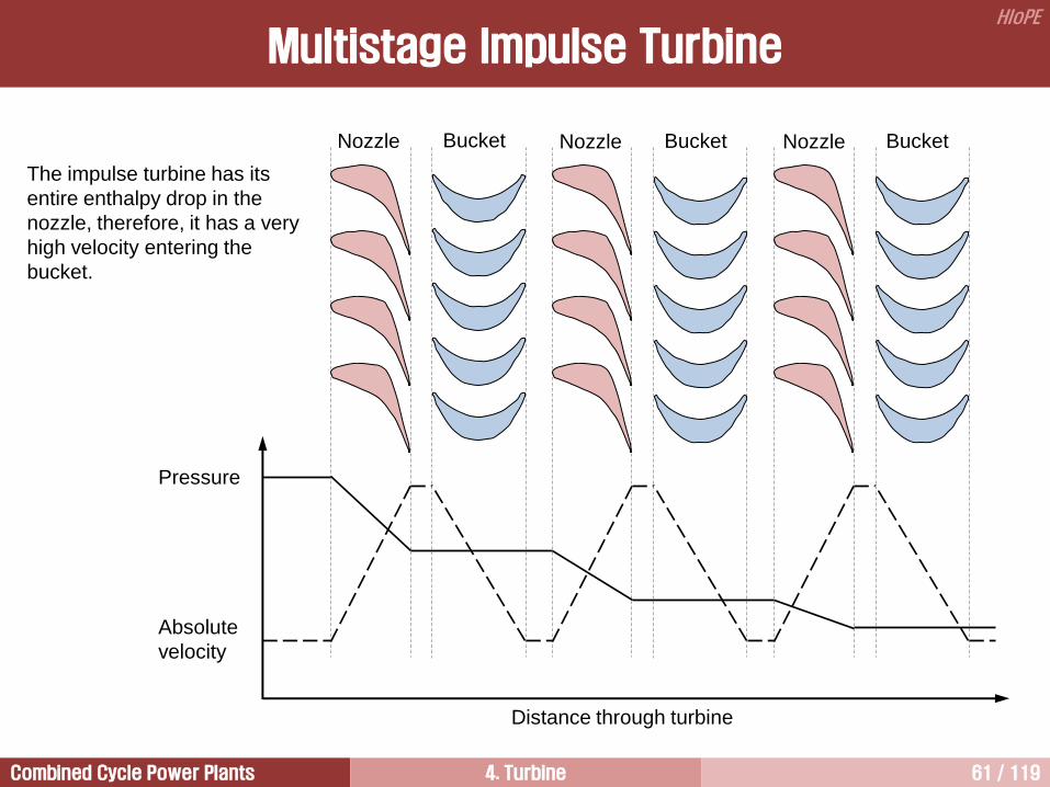
The impulse turbine has its
entire enthalpy drop in the
nozzle, therefore, it has a very
high velocity entering the
bucket.
Multistage Impulse Turbine
Pressure
Absolute
velocity
Distance through turbine
Nozzle Bucket Nozzle Bucket Nozzle Bucket

Combined Cycle Power Plants 4. Turbine 62 / 119
HIoPE
Pressure
Absolute
velocity
Distance through turbine
Nozzle Bucket Nozzle Bucket Nozzle Bucket
half of impulse turbine
Multistage Reaction Turbine

Combined Cycle Power Plants 4. Turbine 63 / 119
HIoPE
Evolution of Steam Turbine Blade
Siemens GEC AEI Rateau SCAM BBC Sulzer AEG
GE USA IMPULSE
Siemens-KWU D REACTION
W/H USA REACTION
BBC CH REACTION
Alsthom F IMPULSE
GEC UK IMPULSE 1970
2000 GE USA IMPULSE
Siemens-Westinghouse D REACTION
ABB-Alsthom F REACTION
MHI J REACTION
Ansaldo
Toshiba
Doosan
Hitachi
1998
N. Piignone
BHEL
Parsons
Fuji
MHI
ABB GEC-Alsthom
1989 1987
CEM
LMZ
Zamech
ASEA STAL
F. Tosi
De Pretto
1999

Combined Cycle Power Plants 4. Turbine 64 / 119
HIoPE
Question
1. Compare the impulse and reaction turbine in terms of SPE.
2. Compare the impulse and reaction turbine in terms of profile loss.
3. Suggest the equation to calculate the thrust produced in a stage.
4. Which type of turbine requires bigger thrust bearings?
5. Single stage supersonic impulse turbine is shown in the figure.
1) Discuss the shape of nozzle path.
2) What is the purpose of the increasing nozzle exiting velocity up to supersonic velocity?
Single stage supersonic impulse turbine
31 ppdlT
T = Thrust
d = mean diameter of blade row
l = active length of blade
p1 = pressure at the inlet of stage
p3 = pressure at the exit of stage
= degree of reaction at the mean dia.
drpprTtip
root
r
r322

Combined Cycle Power Plants 4. Turbine 65 / 119
HIoPE
Comparison of Leakage [1/2]
[ Impulse stage ] [ Reaction stage ]
Gas turbines have internal sealing systems between the rotating buckets and the stationary casing.
The rotating bucket to stationary casing seal is more critical in a reaction turbine than in an impulse turbine
since the reaction turbine has higher pressure drop across the buckets.
However, the impulse turbine has a smaller rotor and thus a smaller sealing diameter, offsetting the effects of
the higher pressure drop.
The reaction stage has a higher profile (aerodynamic) efficiency than an impulse stage.
The impulse stage has higher efficiency on stages with small blade heights because the difference in
leakage losses offsets the higher profile of the reaction stage.
As the blade height increases, the influence of leakage losses decreases and a point is reached where the
reaction stage is more efficient.

Combined Cycle Power Plants 4. Turbine 66 / 119
HIoPE
증기터빈과 달리 가스터빈
노즐에서는 누설손실 발생하지 않음
이는 가스터빈을 통과하는 연소가스
온도가 터빈 블레이드 냉각이 요구될
정도로 높기 때문에 터빈 디스크
내부로 유입되면 안 되기 때문임
가스터빈에서는 압축기로부터
추출한 냉각공기를 버켓
허브(루트)와 노즐 사이 틈을 통해
주유동에 합류시킴으로써 고온의
작동유체가 터빈 디스크 내부로
유입되는 것을 방지
결론적으로 가스터빈 노즐에서는
누설손실이 발생하지 않으며, 이로
인해 증기터빈과 달리 노즐 실에서의
누설은 가스터빈 효율에 영향을
미치지 못함
Comparison of Leakage [2/2]

Combined Cycle Power Plants 4. Turbine 67 / 119
HIoPE
Comparison of the Number of Turbine Stages [1/3]
The number of turbine stage of the reaction turbine is double of the impulse turbine.
The less the number of turbine stages, the less gas turbine cost. This is because the cost of the gas turbine
blade is very high.
In addition, the vibration characteristics of the gas turbine becomes worse as the number of turbine stage
increases.
The number of turbine stage can be minimized by the employment of impulse turbine. This is because the
pressure and temperature of the working fluid decrease more rapidly when it pass through an impulse stage
than reaction turbine. Therefore, the number of turbine stages operated under the high temperatures can be
reduced by the employment of impulse stages.
In general, the blade cost operated under high temperatures is very high because of both cooling problems
and high cost base materials.
However, impulse turbine shows less turbine efficiency than reaction turbine.
In the case of four stages turbine, front two stages are designed by impulse turbine and rear two stages are
designed by reaction turbine to reduce gas turbine cost and to obtain high turbine efficiency.
In addition, impulse blades are thicker than reaction ones. Therefore, impulse blades have advantages of
installation of cooling passage inside the blades.

Combined Cycle Power Plants 4. Turbine 68 / 119
HIoPE
Impulse Reaction
Let us consider a nozzle row only. This is
because there is no heat addition
and work out
Neglecting inlet velocity
Assume
• h across fixed blades in reaction turbine is only 1/4 that of impulse turbine.
• Reaction turbines, however, have an additional equivalent h across the moving blades.
• Therefore, total h in reaction turbine is a half of impulse turbine.
• This means that reaction turbine needs twice number of stages to generate same output.
outin wPEKEFEuq outin wchchq 2
22
2
112
1
2
1
2
1
2
2212
1
2
1cchh
2
221 ch 2
221 ch
o902
uc 22 uc 2
22uh 25.0 uh
Comparison of the Number of Turbine Stages [2/3]

Combined Cycle Power Plants 4. Turbine 69 / 119
HIoPE
F = mV = m(c2sin2 + c3sin3)
= mc2sin2
P = mc2sin2u
F = mV = m(c2sin2 + c3sin3)
= mc2sin2
P = mc2sin2u
Impulse Turbine Reaction Turbine
2
2
3
3
w3
w2
c2
u
u
c3
w2sin2
w3sin3
u u
2u = c2sin2
2
3
w3
w2
c2
u
u
c3
u = c2sin2
w3sin3
u u
Comparison of the Number of Turbine Stages [3/3]

Combined Cycle Power Plants 4. Turbine 70 / 119
HIoPE
노즐의 역할은 작동유체의 압력에너지를 운동에너지로 변환시키는 것이다. 따라서 노즐을 통과한 작동유체는 속도가 크게 증가한다. 그러나 연속방정식에 의해 노즐 출구에서의 축방향 속도는 노즐 입구에서와 동일하기 때문에 접선방향 속도만 크게 증가한다. 이로 인해 노즐 출구를 빠져 나온 작동유체는 큰 선회유동으로 인해 원심력이 발생하여 유체는 버켓 팁(tip) 쪽으로 집중되는 경향을 가진다.
유동이 버켓 팁 쪽으로 편중되면 버켓과 케이싱 사이에서 누설손실이 증가하며, 버켓 팁 근처에서 이차유동손실이 증가할 뿐만 아니라 반경방향을 따라서 버켓에서 생산하는 동력도 균일하지 못하게 된다.
이런 문제를 해결하기 위해서 버켓 팁 입구 쪽의 압력을 루트(root, or hub) 입구 쪽 압력보다 높게 유지시킨다. 이 경우 버켓 입구의 팁부분 압력이 루트부에 비해 높기 때문에 팁 쪽에서 루트 방향으로 진행하는 유동이 형성된다.
그런데 버켓 팁 쪽에 형성되는 높은 압력으로 인해 루트 쪽으로 진행하려는 힘과 원심력에 의해 루트에서 팁 쪽으로 진행하려는 두 힘은 서로 방향이 반대이기 때문에 두 힘의 크기를 비슷하게 해주면 노즐과 버켓 사이에서 유동은 축방향으로 평행하게 흘러가며, 앞서 언급된 제반 문제점들이 사라지게 된다.
따라서 노즐과 버켓 사이에 형성되는 유동의 특징은 반경방향을 따라서 속도는 줄어들고, 압력은 증가한다.
한편, 축류형 다단 터빈은 버켓 입구에서 뿐만이 아니라 출구에서도 압력과 속도는 반경방향을 따라서 일정하게 유지되어야 한다.
따라서 버켓은 루트에서 팁 쪽으로 가면서 반동도가 증가하기 때문에 버켓 루트는 충동형, 팁은 반동형으로 설계한다.
이런 이유 때문에 터빈 버켓은 하나의 블레이드에 충동형과 반동형이 혼재된 충동-반동 블레이드(impulse-reaction blade)이다.
Impulse-Reaction Turbine [1/4]

Combined Cycle Power Plants 4. Turbine 71 / 119
HIoPE
True impulse stages having 0% reaction and reaction stages that always have 50% reaction do not exist in
practical turbine design.
The amount of reaction in a blade varies to accommodate the natural variation of reaction with blade height.
Impulse stages typically have 3% to 5% reaction at the root of bucket in order to avoid zero or negative
reaction that results in efficiency loss and may lead to flow separation in the bucket.
For long reaction stage buckets, the degree of reaction at the mean diameter may be as low as 40%.
Thus, impulse and reaction stages in the classical definition do not exist in practical turbines.
Characteristics of flow behaviors in multistage axial turbine stage:
1) Pressure and velocity distributions along radial direction are uniform at the entry of a stage.
2) This is same as at the exit of a stage.
3) Centrifugal forces are caused by the tangential component of flow in the nozzle discharge.
4) This is same as in the reaction turbine.
5) The variation of reaction in radial direction is needed to partially cancel the centrifugal forces in the
stage.
6) Otherwise, the flow would migrate to the tip, resulting in a poor stage efficiency due to as followings.
• Increase of bucket tip leakage loss
• Increase of secondary flow loss near bucket tips
• Bucket vibration characteristics becomes worse because of non-uniform load acting on the bucket
along radial direction
Impulse-Reaction Turbine [2/4]

Combined Cycle Power Plants 4. Turbine 72 / 119
HIoPE
1000
psia
1000
psia
1000
psia
859.4 psia
844.1 psia
828.7 psia
819.7
psia
819.7
psia
819.7
psia
Free vortex design impulse type
HP turbine stage
22% @ tip
13.5%
@ pitch
5% @ root
[ Example of pressure variation in radial direction ]
버켓 팁으로의 유동편중 해결 방법
Impulse-Reaction Turbine [3/4]

Combined Cycle Power Plants 4. Turbine 73 / 119
HIoPE
• Velocity and pressure distribution along radial direction are uniform at
the inlet and outlet of the stage.
• Velocity decreases along radial direction between nozzle and bucket.
• Pressure increases along radial direction between nozzle and bucket.
Radial Variation of Flow Parameters
Impulse-Reaction Turbine [4/4]
c1 c3
p1 p2 p3
c2
w2R
w2M
w2T
uR
uM
uT
c2R
c2M
c2T

Combined Cycle Power Plants 4. Turbine 74 / 119
HIoPE
Higher aerodynamic efficiency
• Low turning and accelerating flow in both nozzle and bucket allow design of higher efficient and tolerant
profiles
• Low acceleration of the flow through the nozzle and bucket leads lower profile loss
Better flexibility with respect to operating range
Lower staging loading
Many stage can be designed with 50% reaction (all HP and IP stages, and front stages of LP turbine)
Symmetric velocity triangle (50% reaction stage)
• Use of same profile in the nozzle and bucket and it may contribute to cost down
• Near-zero interstage swirl
Because of the lower pressure drop, there is no need for costly diaphragm construction
Reaction Blades
Advantages Alstom
It leads larger number of stages because of lower stage loading (roughly twice that of impulse stages for
50% reaction stages).
Increase of axial thrust which leads higher dummy balance piston, i.e. increased leakage loss.
Drum-type rotor is suitable for reaction turbine and it leads higher leakage area at the hub section.
Degree of reaction at the hub and tip section is higher compared with impulse stage. Higher hub reaction
leads lower leakage loss, however higher tip reaction gives higher leakage loss.
Disadvantages

Combined Cycle Power Plants 4. Turbine 75 / 119
HIoPE
The pitch line reaction should be around 0.5 for best efficiency. The efficiency decreases as the reaction
reduces. This is because profile loss increases as the reaction reduces.
However, it may be reduced as low as 0.3 when the blade temperature is borderline with respect to creep or
oxidation.
This will increase the nozzle exit velocities and bucket inlet relative velocities, reducing the static
temperature and hence also the bucket metal temperatures.
It also reduce the rearwards axial thrust load.
Hub reaction should ideally always be greater than 0.2.
Degree of Reaction in Practical Turbines

Combined Cycle Power Plants 4. Turbine 76 / 119
HIoPE
Impulse and Reaction Turbines 4
Introduction 1
Dimensionless Numbers 3
Thermodynamics and Fluid Dynamics for Turbines 2
Advanced Vortex Blades 6
Stage Efficiency 5
Blade Materials 7
Blade Cooling 8

Combined Cycle Power Plants 4. Turbine 77 / 119
HIoPE
Stage Efficiency
2, sin4ist
2
2
max,, sin ist
2c
u
ideal
actualst
p
p
버켓에서 생산하는 실제 동력
버켓에서 생산할 수 있는 이상 동력
=
( = velocity ratio)
(from ) 0,
d
ist
2
2
2,
sin21
sin22
rst
2
2
2
2
max,,sin1
sin2
rst
2c
u
Impulse Turbine Reaction Turbine
2
2
u
c2 w3
w2
3
c3
3
(a) < sin2
w3
w2
c2
u
c3
(b) = sin2
c2 w3
u
w2 c3
(c) > sin2
w2
c2
u
w3 c3
2
2
3

Combined Cycle Power Plants 4. Turbine 78 / 119
HIoPE
0.25 0.50 0.75 1.00 1.25 1.50
Velocity ratio ( )
0.0
0.1
0.2
0.3
0.4
0.5
0.6
0.7
0.8
0.9
1.0
1.1
Sta
ge
eff
icie
ncy
Impulse Reaction
2
2
2,
sin21
sin22
rst
2, sin4ist
2c
u
Stage Efficiency

Combined Cycle Power Plants 4. Turbine 79 / 119
HIoPE
Velo
city
Number of revolution
1 2
Reaction stage has better adaptability for
core flow of nozzle and higher stage
efficiency
The wake is a velocity defect generated by the
boundary layers of the blade surfaces. If is
undisturbed by other blades it would move
downstream along the direction of outlet-flow angle
while decaying slowly over three or four chord
lengths.
Wake and Core Flow
Wake (후류)

Combined Cycle Power Plants 4. Turbine 80 / 119
HIoPE
Wake and Core Flow
Impulse
bucket Reaction
bucket

Combined Cycle Power Plants 4. Turbine 81 / 119
HIoPE
Impulse and Reaction Turbines 4
Introduction 1
Dimensionless Numbers 3
Thermodynamics and Fluid Dynamics for Turbines 2
Advanced Vortex Blades 6
Stage Efficiency 5
Blade Materials 7
Blade Cooling 8

Combined Cycle Power Plants 4. Turbine 82 / 119
HIoPE
Endwall
Le
ad
ing e
dge
of
bla
de
s1 s2
Formation of Horseshoe Vortex
Horseshoe vortex formed around a
square bar
Horseshoe vortex formed around a
round bar
Nozzle Profile
(15%)
Bucket
Profile
(15%)
Nozzle
Secondary
(15%) Bucket Secondary
(15%)
Tip
Leakage
(22%)
Shaft Packing
Leakage
(7%)
Root Leakage (4%) Rotation (3%) Carryover (4%)

Combined Cycle Power Plants 4. Turbine 83 / 119
HIoPE
Endwall flow produces endwall boundary layer.
Endwall flow is one of major sources of turbine losses,
especially in cascades with short length blades and
high flow turning.
The endwall losses occupy a substantial part of the
total aerodynamic losses in a nozzle or bucket row,
even as high as 30~50%.
The boundary layer fluid upstream of the leading edge
is decelerated by the adverse pressure gradient and
separates at a saddle point s1.
The boundary layer fluid elements form a reverse
recirculating flow just before the leading edge.
Formation of Horseshoe Vortex
Stream surface
Inlet
boundary
layer
Endwall
crossflow
Endwall
Counter vortex
Passage vortex
This reverse flow produces another saddle point s2.
The upstream boundary layer is rolled-up in the recirculating zone and it is divided into two legs at the
leading edge saddle point of the blade and forms the so-called horseshoe vortex.
Then, one leg goes into suction side and the other leg goes into pressure side in axial cascades.

Combined Cycle Power Plants 4. Turbine 84 / 119
HIoPE
Secondary flow means various vortices
passing through blade-to-blade passage in
axial turbines.
The pressure side leg moves towards the
suction side of neighboring blade in the
passage due to the tangential pressure
gradient and becomes the passage vortex.
The suction side leg called as the counter
vortex rotates in the opposite direction to the
larger passage vortex.
There are two distinct (but arising from the
same physical phenomena) vortices are
present on the suction side of blades and
they may merge, interact or stay separate.
Counter vortex is also called as “stagnation
point vortex”, or “leading edge vortex”, or
“horseshoe vortex”.
Secondary Flow
Stream
surface Inlet
boundary
layer
Endwall
crossflow
Endwall
Counter vortex
Passage vortex

Combined Cycle Power Plants 4. Turbine 85 / 119
HIoPE
Free vortex design Advanced vortex design
Hub
Tip
High
efficiency
area
Rad
ial h
eig
ht
Bucket efficiency
Secondary Flow Loss
Stream surface
Inlet
boundary
layer
Endwall
crossflow
Endwall
Counter vortex
Passage vortex

Combined Cycle Power Plants 4. Turbine 86 / 119
HIoPE
Free vortex blade
Leaned blade
Compound leaned blade
(Advanced vortex blade)
Concepts
Advanced Vortex Blade

Combined Cycle Power Plants 4. Turbine 87 / 119
HIoPE
[ M501G stage 3 vane segment ]
[ M501G stage 4 vane segment ]
Evolution of Turbine Blades
In order to reduce the secondary flow losses
in turbine stages, radial velocity components
are accounted for by using CFD techniques.
Radial flow distribution is biased toward the
more efficient mid-section of the bucket by the
redistribution of the exit angle of nozzle blade.
According to the open literature from GE,
stage efficiency of the steam turbine can be
improved 0.5 to 1.2% by the employment of
advanced vortex blades.
Nozzle solidity is reduced to allow use of
more efficient blade profiles.
Root reaction is moderately increased to
increase efficiency, and tip reaction is
decreased to reduce bucket tip leakage
losses.

Combined Cycle Power Plants 4. Turbine 88 / 119
HIoPE
The efficiency of an axial-
flow turbine, which in
modern new advanced
gas turbine, reaches
about 92%.
Evolution of the First Stage Bucket
Design c
Increased c
Reduced c u
u
u
w
Increased
inlet angle
Decreased
inlet angle Hub
Tip
Annulus
height mean
actual
Inlet Middle ~ Exit

Combined Cycle Power Plants 4. Turbine 89 / 119
HIoPE
Source: Siemens
Secondary flow loss can be reduced remarkably
by the adoption of leaned blades
Efficiency Gain with 3D Blades

Combined Cycle Power Plants 4. Turbine 90 / 119
HIoPE
Impulse and Reaction Turbines 4
Introduction 1
Dimensionless Numbers 3
Thermodynamics and Fluid Dynamics for Turbines 2
Advanced Vortex Blades 6
Stage Efficiency 5
Blade Materials 7
Blade Cooling 8

Combined Cycle Power Plants 4. Turbine 91 / 119
HIoPE
Creep is a term used to describe the
permanent elongation which occurs to
rotating parts.
Creep is most pronounced in turbine
blades because of the heat loads and
centrifugal loads imposed during operation.
Each time a turbine blade is heated,
rotated, then stopped (referred to as engine
cycle), it remains slightly longer than it was
before.
The additional length may be only millions
of an inch under normal circumstances or,
after an engine over temperature or, over
speed condition, very much longer.
Creep [1/4]
o
Permanent
elongation
a b
c
d
Str
ess
Strain
a: yield stress
c: ultimate stress
d: fracture
o-a: elastic behavior
a-d: plastic behavior
e

Combined Cycle Power Plants 4. Turbine 92 / 119
HIoPE
Schematic of material placed in
tension with a small elastic
extension
The effect of extended service on material structure at an
elevated temperature, with the material subject to a tensile
stress
Creep [2/4]

Combined Cycle Power Plants 4. Turbine 93 / 119
HIoPE
Creep [3/4] S
train
Primary
phase
Tertiary
phase
Time
Secondary
phase
Tensile force

Combined Cycle Power Plants 4. Turbine 94 / 119
HIoPE
Nevertheless, if the blade remains in service long enough, changes are that it will eventually make contact
with its shroud ring an begin to wear away.
When this occurs, an audible rubbing can be heard on engine.
Creep can be thought of as occurring in three stages: Primary, secondary, and tertiary.
The primary and tertiary stages occur relatively quickly. Primary creep occurs during the engine’s first run,
tertiary during operating overloads.
But the secondary creep stage occurs quite slowly (flat portion on the strain/time graph). It is within the
secondary creep region that the engine manufacturer bases the turbine’s service life.
Causes for accelerated (tertiary) creep:
- Over temperatures;
- Extended operation at high power;
- Erosion of the blades from ingestion of foreign objects.
Creep [4/4]

Combined Cycle Power Plants 4. Turbine 95 / 119
HIoPE
Superalloys are complex mixtures of many critical metals, such as nickel, chromium, cobalt, titanium,
tungsten, carbon, and other metallic elements.
General agreement on precise mixtures by manufacturers of turbine parts is still the subject of much debate.
One reason for this is that the strength properties these metals ultimately have depends on the mixture.
However, the stronger the metal, the more difficult and expensive it is to form and machine into the
complicated shapes necessary for turbine engine parts.
Superalloys were developed for use in high temperature areas where oxidation resistance is required and
where high thermal, tensile, and vibratory stresses are present.
Superalloys have a maximum temperature limit of 2000F when uncooled and 2600F when cooled
internally.
Nickel-base superalloys contain little or no iron, are noncorrosive, and can be worked in thin weldable
sheets.
Thus, nickel-base superalloys, often referred as inconel (a trade name), are used often to construct
combustor liners, turbine cases, and turbine blades.
Turbine nozzles and buckets are either forged by newer powder metallurgy technique or by traditional
methods, or investment cast from nickel-base alloys. They are also cast by single crystal methods. These
materials have very high temperature strength under centrifugal loads and are highly corrosion resistant.
Blade Materials [1/4]
Nickel-base Superalloys Source: Otis and Vosbury, “Aircraft gas turbine powerplants”, Jeppessen, 2001.

Combined Cycle Power Plants 4. Turbine 96 / 119
HIoPE
[ Directional solidification ]
[ Single crystal ]
Low Creep characteristics High
Ingot price: 1 2 5
Application in aviation: 1970 1982
Application in power generation: 1987 1990
Blade Materials [2/4]

Combined Cycle Power Plants 4. Turbine 97 / 119
HIoPE
At elevated temperatures, component failure begins and progresses through grain boundaries. The equiaxed
process assures uniformity of the grain structure along all their axes.
DS blade has a grain structure that runs parallel to the major axis of the part and contains no transverse
grain boundaries. DS was introduced by P&W in 1965.
The elimination of these transverse grain boundaries improves creep and rupture strength on the alloy, and
the orientation of the grain structure provides a favorable modulus of elasticity in the longitudinal direction to
enhance fatigue life.
In addition to improved creep life, the DS blades possess more than 10 times the strain control or thermal
fatigue compared with aquiaxed blades.
Because grain boundaries remain the weak link in turbine blades, numerous techniques have been used to
strengthen them. Even better than strengthening grain boundaries is eliminating them by producing parts
consisting of a single crystal.
By eliminating all grain boundaries and the associated grain boundary strengthening additives, a substantial
increase in the melting point of the alloy can be achieved, thus providing a corresponding increase in high-
temperature strength.
In SC blades, all grain boundaries are eliminated from the material structure and a single crystal with
controlled orientation is produced in an airfoil shape. SC blades offer additional creep and fatigue benefits
through the elimination of grain boundaries.
The advantage of SC alloys compared with equiaxed and DS alloys in low-cycle fatigue (LCF) life is
increased by about 10%.
Blade Materials [3/4]

Combined Cycle Power Plants 4. Turbine 98 / 119
HIoPE
The directional solidification process results in large MC-type carbides in some alloys, and these carbides
are often precracked and initiate matrix fatigue cracks under cyclic loading conditions.
If some grain boundaries are not perfectly aligned with the solidification direction, creep cracks may initiate
at these boundaries where they intersect a free surface.
The removal of grain boundary strengthening
elements, including C, B, Zr, and Hf, might
improve the fatigue properties by elimination of
MC carbides and could increase the incipient
melting temperature and therefore the creep
resistance, because these elements are melting-
point depressants.
In the absence of grain boundaries, more flexibility
in alloying might be achieved that would result in
an optimum balance of creep-rupture strength and
oxidation and hot corrosion resistance.
Development of leaner alloys also improves
castability.
Equiaxed
DS
SC
Creep
strength
Thermal
fatigue
resistance
Corrosion
resistance
Re
lative
Life
0
2x
4x
6x
8x
10x
Blade Materials [4/4]

Combined Cycle Power Plants 4. Turbine 99 / 119
HIoPE
Construction Process
1) Turbine disk forging by use of powder metals.
a) A forming case is filled with powder metal and placed in a vacuum chamber.
b) A forming case is vibrated to tightly pack the powder. The vacuum prevents air voids in the mixture.
c) The metal powder is subjected to very high mechanical pressure of approximately 25,000 psi. High heat
is supplied sufficient to melt the metal particles together into a disk-shaped piece.
2) Compressor rotor and stator blade investment casting.
a) Molten metal is poured into a ceramic mold in a furnace then taken out to cool.
b) The mold is broken away and the blade comes out in a near final shape.
c) The part is machined to its final shape.
3) Turbine blade casting by the “lost wax method” (see next page)
4) Turbine blade casting by the “single crystal method”
Accomplished as above for directional solidification except that the molten metal is drawn into the mold
through a small corkscrew channel at one end while the other end is chilled.
Source: Otis and Vosbury, “Aircraft gas turbine powerplants”, Jeppessen, 2001.

Combined Cycle Power Plants 4. Turbine 100 / 119
HIoPE
Blade Construction Process
Lost Wax Method
1) A wax copy of the piece is made in
a metal mold.
2) The wax piece is dipped in liquid
ceramic to form a coating.
3) Molten metal is poured into the
ceramic casting furnace and wax
leaves the mold.
4) During cooling, the casting is
centrifugally loaded in a spin-
chamber to provide a directional
solidification to the piece resulting in
a long grain structure. After
solidification the ceramic shell is
broken off and the piece is
processed into a finished part.

Combined Cycle Power Plants 4. Turbine 101 / 119
HIoPE
Impulse and Reaction Turbines 4
Introduction 1
Dimensionless Numbers 3
Thermodynamics and Fluid Dynamics for Turbines 2
Advanced Vortex Blades 6
Stage Efficiency 5
Blade Materials 7
Blade Cooling 8
Combined Cycle Power Plants 4. Turbine 102 / 119
HIoPE
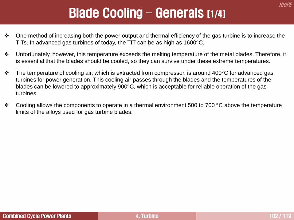
One method of increasing both the power output and thermal efficiency of the gas turbine is to increase the
TITs. In advanced gas turbines of today, the TIT can be as high as 1600C.
Unfortunately, however, this temperature exceeds the melting temperature of the metal blades. Therefore, it
is essential that the blades should be cooled, so they can survive under these extreme temperatures.
The temperature of cooling air, which is extracted from compressor, is around 400C for advanced gas
turbines for power generation. This cooling air passes through the blades and the temperatures of the
blades can be lowered to approximately 900C, which is acceptable for reliable operation of the gas
turbines
Cooling allows the components to operate in a thermal environment 500 to 700 C above the temperature
limits of the alloys used for gas turbine blades.
Blade Cooling – Generals [1/4]

Combined Cycle Power Plants 4. Turbine 103 / 119
HIoPE
1965 1975 1985
Te
mp
era
ture
, C
1800
Year
1950 1955 1960 1970 1980 1995 1990 2005 2000 2015 2010 2025 2020
1700
1600
1500
1400
1300
1200
1100
1000
900
800
700
600
S-816
N80A M252
U500 U700 IN738 IN939 IN792 DS
Single crystal
Material improvement
TBC
Film cooling Turbine inlet temperature
Benefits of
cooling
Blade Cooling – Generals [2/4]

Combined Cycle Power Plants 4. Turbine 104 / 119
HIoPE
Source: Recent Advances of Internal Cooling Techniques for Gas Turbine Airfoils Minking K Chyu and Sin Chien Siw, J. Thermal Sci. Eng. Appl. 5(2), 021008 (May 17, 2013)
Tip cap
cooling holes
Film cooling
holes
Trailing edge
cooling slots
Blade platform
cooling holes Impingement
cooling
Dovetail
Cooling air
Squealer tip
Hot gas
Film
cooling
Rib turbulators
Shaped internal cooling passage
Trailing edge
ejection
Tip cap cooling
Rib turbulated
cooling
Pin-fin cooling
Cooling air
Hot gas
Blade Cooling – Generals [3/4]
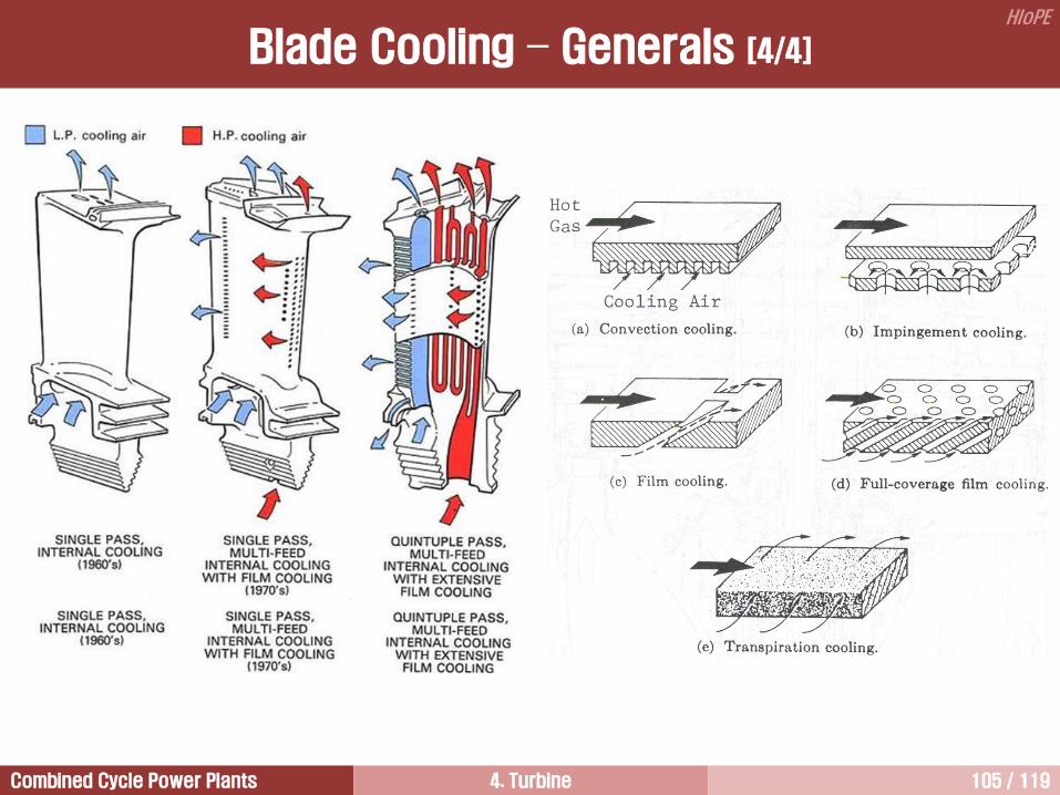
Combined Cycle Power Plants 4. Turbine 105 / 119
HIoPE
Blade Cooling – Generals [4/4]

Combined Cycle Power Plants 4. Turbine 106 / 119
HIoPE
Cooling Air Supply and Its Flow [1/2]

Combined Cycle Power Plants 4. Turbine 107 / 119
HIoPE
Cooling Air Extraction
Cooling Air Supply and Its Flow [2/2]

Combined Cycle Power Plants 4. Turbine 108 / 119
HIoPE
Impingement
cooling
Film
cooling
Rib turbulators
Shaped internal cooling passage
Trailing edge
ejection
Tip cap cooling
Rib turbulated
cooling
Pin-fin cooling
Cooling air
Hot gas
1. Convection Cooling [1/2]
This is the most widely used cooling concept in modern
gas turbines.
Cooling air flows inside the turbine blade and removes
heat from the walls of cooling air passages.
In order to increase the heat transfer surface area, single
pass has been change into multi-pass, that is serpentine
passages.
Additionally, in order to augment heat transfer coefficient,
heat transfer surface treatments have been employed,
such as rib-rougheners or turbulators, and pin-banks or
pin-fins.
TThAq w

Combined Cycle Power Plants 4. Turbine 109 / 119
HIoPE
1. Convection Cooling [2/2]
Due to manufacturing constraints in the very narrow
trailing edge of the blade, pin-fin cooling is typically used
to enhance the heat transfer in this region.
In a pin-fin array heat is transferred from both the
smooth channel endwall and the numerous pins.
Flow around the pins in the array is comparable to the
flow around a single cylinder.
As the cooling air flows past the pin, the flow separates
and wakes are shed downstream of the pin.
In addition to this wake formation, a horseshoe vortex
forms just upstream of the base of the pin, and the
vortex wraps around the pins. This horseshoe vortex
creates additional mixing, thus increases heat transfer.
There are two array structures commonly used. One is
the inline array and the other is the staggered array.
Pin-Fin Cooling
Pin-fin

Combined Cycle Power Plants 4. Turbine 110 / 119
HIoPE
2. Film Cooling [1/2]
Cooling air, which is extracted from the last stage of
compressor and passed through the internal cooling
passage of the blade, is injected through small holes
on the blade surface and forms an insulating layer
between the hot mainstream gas and the blade
surface.
This cooling air film protects the turbine blades from
hot gases with very high temperatures.
Additionally, this cooling air film acts as a heat sink,
consequently reducing heat transfer to the walls.

Combined Cycle Power Plants 4. Turbine 111 / 119
HIoPE
2. Film Cooling [2/2]
Temperature F
Turbine inlet 1630
Average metal 1613
Maximum surface 1700
Cooling T 17
Turbine inlet 1819
Average metal 1452
Maximum surface 1650
Cooling T 357
Turbine inlet 2025
Average metal 1390
Maximum surface 1615
Cooling T 635
Turbine inlet 2300
Average metal 1400
Maximum surface 1600
Cooling T 900
W501A
(1968)
And
W501AA
(1970)
W501B
(1973)
W501D5
(1980)
501F
(1990)

Combined Cycle Power Plants 4. Turbine 112 / 119
HIoPE
Impingement cooling is commonly used near the leading
edge of the blades, where heat loads are the greatest.
Especially, the leading edge is well suitable for impingement
cooling because it has a blunt shape.
Cooling air is impinged on the inner surface of the airfoil by
high-velocity air jets, permitting an increased amount of heat
to be transferred to the cooling air from the metal surface.
This cooling method can be restricted to desired sections of
the airfoil to maintain even temperatures over the entire
surface.
For example, the leading edge of a blade needs to be cooled
more than the mid-chord section or trailing edge, so the gas
is impinged.
3. Impingement Cooling

Combined Cycle Power Plants 4. Turbine 113 / 119
HIoPE
Cooling requires the coolant flow to pass through the porous wall of the blade material.
The heat transfer takes place directly between the coolant and the hot gas.
This cooling is effective at very high temperatures, since it covers the entire blade with coolant flow.
4. Transpiration Cooling
Cooling
air film
Cooling air
Hot gas Porous
material

Combined Cycle Power Plants 4. Turbine 114 / 119
HIoPE
The development of directional solidification and single crystal casting technologies have increased alloy
operation temperatures, thus contributed to increase TIT.
Then, gas turbine materials developments have moved to thermal barrier coating, as the temperature
capability of Ni-based superalloys approaches their intrinsic limit.
Ceramic is used as a coating material because it has very low thermal conductivity. Thus, coating layer can
reduce the blade surface temperature by insulating it from the hot gas.
TBCs are composed of two layers: a bond coat with diffusion aluminide or MCrAlY, and a top coat with
material having low thermal conductivity.
The aluminide coatings with platinum increase the oxidation resistance and also the corrosion resistance.
The thermal barrier coatings have an insulation layer of 100 to 300 m thick and are based on ZrO2-Y2O3
and can reduce metal temperatures by 100~150C.
Coatings ensure that the lives of the blades are extended and in many cases are used as sacrificial layer,
which can be stripped and recoated.
Life of coatings depends on composition, thickness, and the standard of evenness where it gas been
deposited.
Ceramic and aluminum alloy thermal barrier coating of superalloy parts are also processes which give high
surface strength and resistance to corrosion.
This coating is said to give the best protection against the scaling type corrosion or erosion which occurs at
high gas temperatures.
Scaling is caused by sodium in the air and sulfur in the fuel reacting chemically with the base metals.
5. Thermal Barrier Coating [1/3]

Combined Cycle Power Plants 4. Turbine 115 / 119
HIoPE
5. Thermal Barrier Coating [2/3]
Thermal barrier
coating (TBC):
100-300 m
Oxidation
resistant bond
coat: 20-30 m
Thermally
grown oxide
(TGO)
Hot
gases
Interior
cooling
air
Nic
ke
l
su
pp
era
lloy
su
bstr
ate
Te
mp
era
ture
Thermal barrier coating
100-150C
Cooling
air temp.
Hot gas
temp.
Distance

Combined Cycle Power Plants 4. Turbine 116 / 119
HIoPE
[ TBC Blades (Siemens) ]
5. Thermal Barrier Coating [3/3]

Combined Cycle Power Plants 4. Turbine 117 / 119
HIoPE
The purpose of the blade cooling is to obtain the highest
overall cooling effectiveness with the lowest possible
penalty on the turbine efficiency.
The ejected coolant interacts with the external flow near
the both endwalls and blade surface. This increases
aerodynamic and thermodynamic losses in the stage.
In optimizing a cooling system, this has to be weighed
against the increase in cycle efficiency that can be
achieved through higher TITs.
In the case of porous blade, the disturbance to the flow
pattern and the wake thickness increases as the coolant
flow increases. Thus, the losses increase.
In a blade with trailing edge slots, the loss initially starts
to increase with coolant flow as the wake thickens.
However, as the coolant flow is increased it tends to
energize the wake and reduce losses. Flow a higher
coolant flow, the coolant flow must be higher, resulting in
an energization of the flow.
Cooled Blade Aerodynamics

Combined Cycle Power Plants 4. Turbine 118 / 119
HIoPE
Hot blade
Warm blades
Temperature increase of blades is caused by the oxidation
blockage of cooling channels.
Creep life of the blade is a strong function of the material
temperature.
It is generally agreed that the life of a turbine blade can be
reduced by half if the blade temperature is higher only 30C than
design temperature.
Loss of coating, especially TBC, can reduce the life of the blade
significantly.
Measurement of Blade Temperature
[ Overheated blade ]
[ Coating erosion ]
[ Coating loss and oxidation damage of
HPT stage 1 bucket (LM6000) ]

Combined Cycle Power Plants 4. Turbine 119 / 119
HIoPE
질의 및 응답
작성자: 이 병 은 (공학박사) 작성일: 2015.02.11 (Ver.5) 연락처: [email protected]
Mobile: 010-3122-2262 저서: 실무 발전설비 열역학/증기터빈 열유체기술