4050 series user manual - amazon web services · model: 4052, 4053, 4054, 4055 function/arbitrary...
TRANSCRIPT
Model: 4052, 4053, 4054, 4055
Function/Arbitrary Waveform Generator
USER MANUAL
2
Safety Summary The following safety precautions apply to both operating and maintenance personnel and must be observed during all phases of operation, service, and repair of this instrument. Before applying power, follow the installation instructions and become familiar with the operating instructions for this instrument.
If this device is damaged or something is missing, contact the place of purchase immediately.
This manual contains information and warnings that must be followed to ensure safe operation as well as maintain the meter in a safe condition.
GROUND THE INSTRUMENT
To minimize shock hazard, the instrument chassis and cabinet must be connected to an electrical ground. This instrument is grounded through the ground conductor of the supplied, three-conductor ac power cable. The power cable must be plugged into an approved three-conductor electrical outlet. Do not alter the ground connection. Without the protective ground connection, all accessible conductive parts (including control knobs) can render an electric shock. The power jack and mating plug of the power cable must meet IEC safety standards.
DO NOT OPERATE IN AN EXPLOSIVE ATMOSPHERE
Do not operate the instrument in the presence of flammable gases or fumes. Operation of any electrical instrument in such an environment constitutes a definite safety hazard.
KEEP AWAY FROM LIVE CIRCUITS
Instrument covers must not be removed by operating personnel. Component replacement and internal adjustments must be made by qualified maintenance personnel. Disconnect the power cord before removing the instrument covers and replacing components. Under certain conditions, even with the power cable removed, dangerous voltages may exist. To avoid injuries, always disconnect power and discharge circuits before touching them.
DO NOT SERVICE OR ADJUST ALONE
Do not attempt any internal service or adjustment unless another person, capable of rendering first aid and resuscitation, is present.
DO NOT SUBSTITUTE PARTS OR MODIFY THE INSTRUMENT
Do not install substitute parts or perform any unauthorized modifications to this instrument. Return the instrument to B&K Precision for service and repair to ensure that safety features are maintained.
WARNINGS AND CAUTIONS
WARNING and CAUTION statements, such as the following examples, denote a hazard and appear throughout this manual. Follow all instructions contained in these statements.
A WARNING statement calls attention to an operating procedure, practice, or condition, which, if not followed correctly, could result in injury or death to personnel.
A CAUTION statement calls attention to an operating procedure, practice, or condition, which, if not followed correctly, could result in damage to or destruction of part or all of the product.

3
WARNING:
Do not alter the ground connection. Without the protective ground connection, all accessible conductive parts (including control knobs) can render an electric shock. The power jack and mating plug of the power cable meet IEC safety standards.
WARNING:
To avoid electrical shock hazard, disconnect power cord before removing covers. Refer servicing to qualified personnel.
CAUTION:
Before connecting the line cord to the AC mains, check the rear panel AC line voltage indicator. Applying a line voltage other than the indicated voltage can destroy the AC line fuses. For continued fire protection, replace fuses only with those of the specified voltage and current ratings.
CAUTION:
This product uses components which can be damaged by electro-static discharge (ESD). To avoid damage, be sure to follow proper procedures for handling, storing and transporting parts and subassemblies which contain ESD-sensitive components.

4
Compliance Statements Disposal of Old Electrical & Electronic Equipment (Applicable in the European Union and other European countries with separate collection systems)
This product is subject to Directive 2002/96/EC of the European Parliament and the Council of the European Union on waste electrical and electronic equipment (WEEE) , and in jurisdictions adopting that Directive, is marked as being put on the market after August 13, 2005, and should not be disposed of as unsorted municipal waste. Please utilize your local WEEE collection facilities in the disposition of this product and otherwise observe all applicable requirements.

5
CE Declaration of Conformity The power supply meets the requirements of 2006/95/EC Low Voltage Directive and 2004/108/EC Electromagnetic Compatibility Directive with the following standards. Low Voltage Directive
- EN61010-1: 2001 - EN61010-031: 2002+A1: 2008
EMC Directive
- EN 61326-1:2006 - EN 61000-3-2: 2006+A2: 2009 - EN 61000-3-3: 2008

6
Safety Symbols
Refer to the user manual for warning information to avoid hazard or personal injury and prevent damage to instrument.
Chassis (earth ground) symbol.
On (Power). This is the In position of the power switch when instrument is ON.
Off (Power). This is the Out position of the power switch when instrument is OFF.
On (Supply). This is the AC mains connect/disconnect switch at the back of the instrument.
Off (Supply). This is the AC mains connect/disconnect switch at the back of the instrument.
Notations TEXT - Denotes a front panel button. TEXT – Denotes a menu option.

7
Table of Contents 1 General Information ................................................................................ 9
1.1 Product Overview ........................................................................................................ 9
1.2 Package Contents ........................................................................................................ 9
1.3 Front Panel Overview ................................................................................................ 10
Front Panel Description .................................................................................................... 10
1.4 Rear Panel Overview ................................................................................................. 11
Rear Panel Description ..................................................................................................... 11
1.5 Display Overview ....................................................................................................... 12
Display Description ........................................................................................................... 12
2 Getting Started ...................................................................................... 12
2.1 Input Power Requirements ....................................................................................... 12
Input Power ...................................................................................................................... 12
2.2 Output Connections .................................................................................................. 13
Impedance Matching ....................................................................................................... 13
2.3 Preliminary Check ...................................................................................................... 14
Check Model and Firmware Version ................................................................................ 16
Output Check .................................................................................................................... 16
3 Front Panel Operation ........................................................................... 17
3.1 Menu Options ............................................................................................................ 17
3.2 Selecting a Channel ................................................................................................... 20
3.3 Configure Waveform Output ..................................................................................... 20
Configure Waveform Shape ............................................................................................. 20
Configure Frequency ........................................................................................................ 22
Configure Amplitude ........................................................................................................ 22
Configure DC Offset .......................................................................................................... 24
Configure Phase ............................................................................................................... 24
Configure Duty Cycle and Symmetry ................................................................................ 25
Configure Pulse Waveform ............................................................................................... 27
Configure Noise Waveform .............................................................................................. 29
Configure Arbitrary Waveform ........................................................................................ 30
Configure DC Output ........................................................................................................ 33
3.4 Configure Modulation ............................................................................................... 34
AM Modulation ................................................................................................................ 34

8
DSB-AM ............................................................................................................................ 35
ASK (Amplitude Shift Keying) ........................................................................................... 37
FM Modulation ................................................................................................................ 38
FSK (Frequency Shift Keying) ............................................................................................ 39
PM Modulation ................................................................................................................ 40
PWM Modulation ............................................................................................................. 41
3.5 Configure Sweep Output ........................................................................................... 43
3.6 Configure Burst .......................................................................................................... 46
3.7 Store and Recall ......................................................................................................... 49
Accessing Store/Recall Menu ........................................................................................... 50
Store and Recall Instrument State .................................................................................... 51
Store and Recall Arbitrary Waveforms ............................................................................. 53
3.8 Utility Functions ........................................................................................................ 55
DC Waveform Output ....................................................................................................... 55
Remote Interface .............................................................................................................. 56
Output Configurations ..................................................................................................... 57
Frequency Counter ........................................................................................................... 60
3.9 System Configurations ............................................................................................... 62
System Settings ................................................................................................................ 63
Self Test and Adjustment .................................................................................................. 67
Check Instrument Information ......................................................................................... 67
Updating Firmware .......................................................................................................... 67
3.10 Help System ........................................................................................................... 68
4 Troubleshooting Guide .......................................................................... 69
5 Specifications ........................................................................................ 70
SERVICE INFORMATION ................................................................................ 75
LIMITED ONE-YEAR WARRANTY ................................................................... 76

9
1 General Information
1.1 Product Overview The B&K Precision 4050 series are dual channel function / arbitrary waveform generators, capable of generating up to 50 MHz sine wave (model 4055). They have an informative easy-to-read color display, user-friendly controls and a numeric keypad which allows users to easily configure waveform properties. In addition, they feature non-volatile built-in memory to create, store, and recall arbitrary waveforms up to 16,000 points with 14-bit vertical resolution. 48 predefined arbitrary waveforms are also available for output. A standard USB interface on the rear panel allows users to easily interface with application software to create and load arbitrary waveforms into the instrument. Features:
Generate sine wave from 1 µHz up to 50 MHz (4055)
3.5-inch TFT-LCD color display
USB interface
16k pts arbitrary waveform memory
48 built-in predefined arbitrary waveforms
Store/recall up to 10 instrument settings
1.2 Package Contents
Please inspect the instrument mechanically and electrically upon receiving it. Unpack all items from the shipping carton, and check for any obvious signs of physical damage that may have occurred during transportation. Report any damage to the shipping agent immediately. Save the original packing carton for possible future reshipment. Every instrument is shipped with the following contents:
4050 series function/arbitrary waveform generator
Getting started manual (printed)
Full instruction manual on CD
AC power cord
USB type A to Type B cable
Certificate of calibration Verify that all items above are included in the shipping container. If anything is missing, please contact B&K Precision. An optional USB to GPIB adapter model AK40G is also available

10
1.3 Front Panel Overview
Front Panel Description
Power On/Off switch
TFT LCD color display
Menu function keys
Waveform buttons
Modulation/Sweep/Burst/Store-Recall/Utility/Help menu buttons
Channel 2 output BNC / Counter input
Channel 1 output BNC
Channel 1 and 2 output On/Off buttons
Arrow keys
Rotary dial knob
Numeric keypad
Channel selection button
USB host port / *USB-to-GPIB adapter interface Accepts USB flash drive to save/recall instrument settings and waveforms. *This port can be used for connecting the USB-to-GPIB adapter (AK40G) accessory. It can also be used for connecting an external USB flash drive.
1 2 3 4 5 6 7
8
9
10 11 12
13
1
2
3
4
5
6
7
8
12
13
9
10
11

11
1.4 Rear Panel Overview
Rear Panel Description
Modulation Input BNC
External Trigger/Gate/FSK/Burst BNC Connector
USB interface
AC input receptacle
Chassis ground
Sync Output BNC
Trigger Input BNC
1 2 3 4
6 7 5
1
2
3
4
5
6
7

12
1.5 Display Overview
Display Description
Waveform information display
Waveform parameters display
Menu options
Output impedance indicator
Selected channel indicator tab
2 Getting Started Before connecting and powering up the instrument, please review and go through the instructions in this chapter.
2.1 Input Power Requirements
Input Power The supply has a universal AC input that accepts line voltage and frequency input within: 100 – 240 V (+/- 10%), 50 – 60 Hz (+/- 5%) 100 – 127 V , 45 – 440 Hz
1
2
3
4
5
1
2
3
4
5

13
Before connecting to an AC outlet or external power source, be sure that the power switch is in the OFF position and verify that the AC power cord, including the extension line, is compatible with the rated voltage/current and that there is sufficient circuit capacity for the power supply. Once verified, connect the cable firmly.
WARNING: The included AC power cord is safety certified for this instrument operating in rated range. To change a cable or add an extension cable, be sure that it can meet the required power ratings for this instrument. Any misuse with wrong or unsafe cables will void the warranty.
2.2 Output Connections The waveform generator output circuits operate as a 50 Ω voltage source working into a 50 Ω load. At higher frequencies, a non-terminated or improperly terminated output may cause aberrations on the output waveform. In addition, loads with an impedance less than 50 Ω will reduce the waveform amplitude, while loads with an impedance greater than 50 Ω will increase waveform amplitude. Excessive distortion or aberrations caused by improper termination are less noticeable at lower frequencies, especially with sine and triangle waveforms. To ensure waveform integrity, follow these precautions:
1. Use good quality 50 Ω coaxial cable and connectors. 2. Make all connections tight and as short as possible. 3. Use good quality attenuators, if it is necessary to reduce waveform amplitudes
applied to sensitive circuits. 4. Use termination or impedance-matching devices to avoid reflections. 5. Ensure that attenuators and terminations have adequate power handling
capabilities. If there is a DC voltage across the output load, use a coupling capacitor in series with the load. The time constant of the coupling capacitor and load must be long enough to maintain pulse flatness.
Impedance Matching If the waveform generator is driving a high impedance, such as a 1 MΩ input impedance (paralleled by a stated capacitance) of an oscilloscope vertical input, connect the transmission line to a 50 Ω attenuator, a 50 Ω termination and to the oscilloscope input. The attenuator isolates the input capacitance of the device and terminates the waveform generator properly.

14
2.3 Preliminary Check Complete the following steps to verify that the generator is ready for use. 1. Verify AC Input Voltage
Verify and check to make sure proper AC voltages are available to power the instrument. The AC voltage range must meet the acceptable specification as explained in section 2.1.
2. Connect Power Connect AC power cord to the AC receptacle in the rear panel and press the power switch to the ON position to turn ON the instrument. The instrument will have a boot screen while loading, after which the main screen will be displayed.
3. Self Test Press Utility, select 1/2 from the menu to enter the second menu page, and select Test/Cal option. Then, select SelfTest option. The instrument has 3 self test options to test the screen, keys, and the LED back lights of the function, menu, and channel output keys.
ScrTest Select this option to do a screen test. The screen will turn into a solid
color background.

15
Press 7 to toggle through red, green, and blue colors. This test checks for dead pixels and color consistencies of the TFT LCD display. Press 8 to exit the test.
KeyTest Select this option to do a key test. The screen will display a silhouette of buttons that represent the front panel buttons.
Press any of the front panel buttons and its corresponding button in the silhouette will turn green. This tests the key press response. If any of the buttons do not change colors on the silhouette when pressed, there may be something faulty with the key. Press 8 three times to exit the test.
LEDTest Select this option to test the function, menu, and channel output buttons’ backlight.
Like the key test, the screen will display a silhouette of buttons that represent the front panel buttons. Press 7 to begin the test. This test will start with the Sine button, which should light up. Its corresponding button in the silhouette should also turn green. Continue to press 7 to toggle through all the buttons with backlights available. At the end of the test, all function, menu, and channel output buttons will light up, and all of their corresponding buttons in the silhouette on the display will turn green. Press 8 to exit the test.

16
4. Self Adjust
This option runs an internal self adjustment procedure that will check and adjust the instrument to specification. Use this option only if the instrument is suspected to be out of calibration. Press Utility, select 1/2 from the menu to enter the second menu page, and select Test/Cal option. Then, select SelfAdjust option. The instrument will run the procedure internally, and a progress bar will be displayed in the waveform information area. When finished, it will show 100% on the progress bar and prompt you to press any function key to continue. Follow the prompt to return to the main display.
Check Model and Firmware Version The model and firmware version can be verified from within the menu system. Press Utility, select 1/2 from the menu to enter the second menu page, and select EditInfo option. The software/firmware version, hardware version, model, and serial number will be displayed. Press any function key to exit.
Output Check Follow the steps below to do a quick check of the settings and waveform output.
1. Turn on the instrument and set the instrument to default settings. To set to default, press Utility, press 1/2 to go to page 2, select System from the menu, and select Set to Default. The instrument will set both channels with the following parameters: Waveform Shape: Sine Frequency: 1.000000 kHz Amplitude: 4.000 Vpp Offset: 0.0 mVdc Phase: 0.0 °

17
Output Impedance: Hi-Z 2. Connect the BNC output of CH1 (yellow) into an oscilloscope. 3. Press the Output button on top of CH1 output BNC to turn on the output and
observe a sine wave with the parameters above. 4. Press the Freq or Period option in the menu and use the rotary knob or the numeric
keypad to change frequency. Observe the changes on the oscilloscope display. 5. Press the Ampl option in the menu and use the rotary knob or the numeric keypad
to change the amplitude. Observe the changes on the oscilloscope display. 6. Press the Offset option in the menu and use the rotary knob or the numeric keypad
to change the DC offset. With the oscilloscope set for DC coupling, observe the changes on the display.
7. Now, connect the BNC output of CH2 (blue) into an oscilloscope and follow steps 3 to 6 to check its output.
3 Front Panel Operation
3.1 Menu Options
All settings and parameters can be configured from the menu system of the instrument. The menu options that are channel specific are the same for both channel 1 and channel 2. Use the key to toggle the channel selection. Some many options are grouped in pairs and can be selected by toggling their corresponding menu function keys. For example:
Function key will toggle selection between frequency or period.
Function key will toggle selection between amplitude or HI level.
Function key will toggle selection between DC offset or LO level.
Function key will toggle selection between phase or equal phase.
Function key will go to page 2/2 menu.
The menu system is organized as follows: Sine
Freq/Period Configures the frequency or period of the waveform. Ampl/HLevel Configures the amplitude or the high level of the waveform. Offset/LLevel Configures the DC offset or the low level of the waveform.
CH1/2

18
Phase/EqPhase Configures the phase or set equal phase relative to the other channel.
Square
Freq/Period Configures the frequency or period of the waveform. Ampl/HLevel Configures the amplitude or the high level of the waveform. Offset/LLevel Configures the DC offset or the low level of the waveform. Phase/EqPhase Configures the phase or set equal phase relative to the other
channel. Duty Configures the duty cycle of the waveform. Ramp
Freq/Period Configures the frequency or period of the waveform. Ampl/HLevel Configures the amplitude or the high level of the waveform. Offset/LLevel Configures the DC offset or the low level of the waveform. Phase/EqPhase Configures the phase or set equal phase relative to the other
channel. Symmetry Configures the symmetry of the waveform. Pulse
Freq/Period Configures the frequency or period of the waveform. Ampl/HLevel Configures the amplitude or the high level of the waveform. Offset/LLevel Configures the DC offset or the low level of the waveform. PulWidth/Duty Configures the pulse width or the duty cycle of the pulse. Delay Configures the delay of the pulse waveform. Noise
Stdev Configures the standard deviation of the noise waveform. Mean Configures the mean value of the noise waveform. Arb
Freq/Period Configures the frequency or period of the waveform. Ampl/HLevel Configures the amplitude or the high level of the waveform. Offset/LLevel Configures the DC offset or the low level of the waveform. Phase/EqPhase Configures the phase or set equal phase relative to the other
channel. Load Wforms Built-In – Access selectable built-in waveforms for output.
Stored Wforms – Access arbitrary waveforms stored in internal memory for output.
Mod
AM Freq/AM Depth/DSB Freq/Key Freq/FM Freq/FM Dev/PM Freq/Phase Dev/PWM Freq/Width Dev
Configures parameters for AM, FM, PM, ASK, FSK, DSB-AM,PWM modulation.
Type Configures the type of modulation. Shape Configures the modulating waveform shape. Source Selects modulating source. Sweep

19
SwpTime Configures the sweep time for sweep output. StopFreq/FrqSp
an Configures the sweep stop frequency or the frequency span of the sweep output.
StartFreq/MidFreq
Configures the sweep start frequency or the center frequency.
Source Selects the sweep source. Trig Out/Edge Internal source: Selects to output a trigger signal at the start
of a sweep operation. External source: Selects to use rising or falling edge from an external trigger for sweep operation.
Linear/Log Selects between linear or logarithmic sweep operation. Direction Selects the sweep direction Trig Manually triggers the sweep operation if the source is set to
manual. Burst
Period Configures the burst period. StartPhase Configures the start phase of the burst output. Ncycle/Gated Selects to burst by number of cycles or selects for external
gated burst. Source/Polarity Selects the source for burst output or selects the polarity for
external gated burst output. Trig Out Selects signal triggering on rising or falling edge. Cycles/Infinite Configures number of cycles for burst or infinite burst
(external source only). Delay Configures the delay of each burst. Store/Recall
FileType Selects the type of files for save/recall. Browser Selects to browser through folders or files on display. Save Saves the selected file into internal or external USB flash
memory. Recall Recalls the selected file from internal or external USB flash
memory. Delete Select to delete the selection. Utility
DC Selects to toggle ON/OFF a DC output. Selectable DC voltages are: 1 V, -1 V, 2 V, -2 V, 5 V, -5 V.
Interface Selects the remote interface. . Output Setup Load – Select output impedance.
Normal/Invert – Select to toggle between normal and inverted output. CHCopy – Copy channel settings between channels. Sync – Select to enable/disable synchronization output with respect to either channel 1 or 2.
Counter Selects built-in counter function. System Access to system settings. Test/Cal Built-in self test and adjustment options. EditInfo Shows information about the generator. Update For firmware updates.

20
Help
3.2 Selecting a Channel The 4050 series function/arbitrary waveform generators have dual channel outputs. They can be operated independently or in sync with each other. To select between channel 1 and 2 and view/change their parameters, toggle the key. When Channel 1 is selected, the display will look like below:
When Channel 2 is selected, the display will look like below:
3.3 Configure Waveform Output
Configure Waveform Shape The instrument can generate many standard as well as arbitrary waveforms. There are waveform keys on the front panel that will switch between different waveform shape to output. Below is a table of waveforms and the corresponding keys to press to generate those waveforms.
CH1/2

21
Waveforms Keys
Sine Sine
Square Square
Ramp Ramp
Pulse Pulse
Noise Noise
Arbitrary Arb
After the waveform selection, menu options relevant for that waveform shape will be shown on the right side of the display. Below illustrates the screenshots shown when each of the waveform types is selected.
Sine Waveform
Square Waveform
Ramp Waveform
Pulse Waveform
Noise Waveform
Arbitrary Waveform

22
Configure Frequency Note: This section does not apply for noise waveform. Follow the steps below to configure the frequency or period of the output. The adjustable frequency range is different for each model and for each type of waveforms. See the specification section for the adjustable ranges.
1. After selecting the waveform shape, there will be a Freq/Period menu option. Press the corresponding menu function key to toggle between selecting frequency or the period to adjust.
2. The cursor position will now highlight the first digit of the frequency parameter display.
3. Use the rotary knob or the numeric keypad to change the frequency. If numeric keypad is used, the below screen will display:
After entering the numeric value, use the menu function keys to select the unit to apply for the frequency setting. Available units are: MHz, kHz, Hz, mHz, uHz.
Configure Amplitude Note: This section does not apply for noise waveform. Follow the steps below to configure the amplitude of the output. The adjustable amplitude range for Channel 1 is 2 mVpp – 10 Vpp into 50 Ω, or 4 mVpp – 20 Vpp into HighZ. For Channel 2, it is 2 mVpp – 3 Vpp into 50 Ω, or 4 mVpp – 6 Vpp into HighZ.
1. From the menu, select Ampl. 2. The cursor position will now highlight the first digit of the amplitude parameter
display. 3. Use the rotary knob or the numeric keypad to change the amplitude. If numeric
keypad is used, the below screen will display:

23
After entering the numeric value, use the menu function keys to select the unit to apply for the amplitude setting. Available units are: Vpp, mVpp, Vrm, mVrm, dbm. Vrm is for Vrms and mVrm is for mVrms. Note: Only using the numeric keypad will allow for changing the units from V to Vrms, mVrms, or dbm.
User Defined High and Low Level The user has the option to adjust the high and low level of the waveform. To do this, toggle the menu function key to select HLevel for high level or LLevel for low level.
Note: DC offset settings will be automatically adjusted if the high and low levels reflect a DC offset.

24
Configure DC Offset Note: This section does not apply for noise waveform. Follow the steps below to configure the DC offset of the output.
1. From the menu, select Offset. 2. The cursor position will now highlight the first digit of the offset parameter display. 3. Use the rotary knob or the numeric keypad to change the offset. If numeric keypad
is used, the below screen will display:
After entering the numeric value, use the menu function keys to select the unit to apply for the offset setting. Available units are: Vdc, mVdc.
Configure Phase Note: This section does not apply for pulse and noise waveforms. Follow the steps below to configure the phase of the output.
1. From the menu, select Phase. 2. The cursor position will now highlight the first digit of the phase parameter display. 3. Use the rotary knob or the numeric keypad to change the phase. If numeric keypad
is used, the below screen will display:

25
After entering the numeric value, use the menu function keys to select the degree (°) unit to apply for the phase setting.
Equal Phase The unit can set both channel 1 and channel 2 to be in phase with a push of one button. From the menu, simply select EqPhase and both channels will be in-phase with respect to each other.
Configure Duty Cycle and Symmetry Note: This section does not apply for pulse and noise waveforms.
Duty Cycle Note: For square waveform only. Follow the steps below to configure the duty cycle of a square waveform.
1. Set the instrument for square wave output by pressing the Square button. 2. From the menu, select Duty. 3. The cursor position will now highlight the first digit of the duty parameter display.

26
4. Use the rotary knob or the numeric keypad to change the duty cycle. If numeric
keypad is used, the below screen will display:
After entering the numeric value, use the menu function keys to select the percent (%) unit to apply for the duty cycle setting.
Note: The adjustable duty cycle range varies depending on the frequency of the waveform. Some frequencies do not allow change of the duty cycle and is fixed at 50%.
Symmetry Note: For ramp/triangle waveform only. Follow the steps below to configure the symmetry of a ramp/triangle waveform.
1. Set the instrument for ramp wave output by pressing the Ramp button. 2. From the menu, select Symmetry. 3. The cursor position will now highlight the first digit of the symmetry parameter
display.

27
4. Use the rotary knob or the numeric keypad to change the symmetry. If numeric
keypad is used, the below screen will display:
After entering the numeric value, use the menu function keys to select the percent (%) unit to apply for the symmetry setting.
Configure Pulse Waveform Note: This section applies to pulse waveform only.
Pulse Width and Pulse Duty Cycle The pulse width and duty cycle parameters are related and both control the length of the high level of the pulse. Users have the option to specify the pulse width in units of seconds or specify duty cycle as a percentage.
Note: The instrument allows for adjusting pulse width at a minimum of 1 ns, however its actual minimum resolution is 8 ns. Therefore, the pulse width change can be observed in increments of 8 ns.

28
Follow the steps below to configure the pulse width or duty cycle.
1. Set the instrument for pulse output by pressing the Pulse button. 2. From the menu, select PulWidth for pulse width adjustment or Duty for duty cycle
adjustment. 3. The cursor position will now highlight the first digit of the width or duty parameter
display.
4. Use the rotary knob or the numeric keypad to change the width or the duty.
After entering the numeric value, use the menu function keys to select the s, ms, us, or ns for pulse width or select percent (%) unit for duty cycle.
Pulse Delay Follow the steps below to configure the pulse delay.
1. Set the instrument for pulse output by pressing the Pulse button. 2. From the menu, select Delay. 3. The cursor position will now highlight the first digit of the delay parameter display.
4. Use the rotary knob or the numeric keypad to change the pulse delay.
After entering the numeric value, use the menu function keys to select the s, ms, us, or ns.

29
Configure Noise Waveform Note: This section applies to noise waveforms only.
Standard Deviation and Mean There are two parameters that can be adjusted of the noise waveform: Standard deviation, mean. Follow the steps below to configure these parameters.
1. Set the instrument for noise output by pressing the Noise button. 2. From the menu, select Stdev for the standard deviation adjustment or Mean for the
mean adjustment. 3. The cursor position will now highlight the first digit of the standard deviation or
mean parameter display.

30
4. Use the rotary knob or the numeric keypad to change the two parameters. Both parameters can be specified in V or mV units.
Configure Arbitrary Waveform There are two ways to generate arbitrary waveforms. Users can output an arbitrary waveform selected from the built-in selection of pre-defined arbitrary waveforms, or create and output a user defined waveform by specifying point by point arbitrary data. This section will explain how to do both.
Generate Predefined Built-in Waveforms There are a total of 48 (including sine, square, and ramp/triangle) predefined built-in arbitrary waveforms that can be output from the generator. They are divided into four categories: Common waveforms, math waveforms, special (project) waveforms, Windowing/trigonometric waveforms.
Note: PPulse and NPulse waveforms are limited to 4.999999 MHz.
Common Waveforms
Command waveforms consist of:
StairUp Upward staircase StairDn Downward staircase
StairUD Down and up staircase PPulse Positive pulse
NPulse Negative pulse Trapezia Trapezoidal

31
UpRamp Upward ramp DnRamp Downward ramp
Math Waveforms
Math waveforms consist of:
ExpFall Exponential fall ExpRise Exponential rise
LogFall Logarithmic fall LogRise Logarithmic rise
Sqrt Square root function Root3 Root three (√𝑥3
) function
X^2 X2 function X^3 X3 function
Sinc Sinc function Gaussian Gaussian function
Dlorentz D-lorentz function Haversine Haversine function
Lorentz Lorentz function Gauspuls Gaussian modulated sinusoidal pulse
Gmonpuls Gaussian mono pulse Tripuls Triangle pulse
Special (project) Waveforms
Special (project) waveforms consist of:
Cardiac Cardiac signal Quake Earthquake
Chirp Frequency sweep cosine TwoTone Two tone signal
SNR Sine with white noise
Window and Trigonometric Waveforms
Window and trigonometric waveforms consist of:
Hamming Hamming window Hanning Hanning window
Kaiser Kaiser window Blackman Blackman window
Gaussian Gaussian window Triangle Triangle window
Haris Haris window Bartlett Bartlett window
Tan Tangent function Cot Cotangent function
Sec Secant function Csc Cosecant function
Asin Inverse sine function Acos Inverse cosine function
Atan Inverse tangent function ACot Inverse cotangent function

32
Follow the steps below to browse and select a predefined arbitrary waveform.
1. Press the Arb button to enter the arbitrary waveform function menu. 2. Select 1/2 from the menu to go to the second page, then select Load Wform. 3. Select Built-In and there will be a table on the waveform display area and four
categories to select from the menu. Select Common to browse the common waveforms. Select Math to browse the math waveforms. Select Project to browse the special (project) waveforms. Select Winfun\Triangle to browse the window and trigonometric waveforms.
4. After making the selection, use the up, down, left, or right arrow keys to select the desired predefined waveform.
5. Once selected, press the Select option from the menu. 6. The generator will return to the main Arb menu and the waveform display area will
show the waveform shape of the selected pre-defined arbitrary waveform. For example, below shows the display of the pre-defined Cardiac signal.
Generate User defined Waveforms The generator has built-in non-volatile memory to store up to 10 user defined arbitrary waveforms, each with a maximum of 16k points.

33
To create an arbitrary waveform, users must use the USB interface in the rear panel for PC connectivity to the EasyWave software, which can be downloaded at www.bkprecision.com .
Note: EasyWave software supports Windows XP/Vista/7 (32 bit and 64 bit) only.
EasyWave software will allow users to easily create a custom arbitrary waveform and load it into the internal memory. To select and output a saved arbitrary waveform from internal memory, follow the steps below.
1. Press the Arb button to enter the arbitrary waveform function menu. 2. Select 1/2 from the menu to go to the second page, then select Load Wform. 3. Select Stored Wforms and there will be a table on the waveform display area with
the file names of all arbitrary waveforms that were created and loaded from EasyWave software.
4. Use the up, down, left, or right arrow keys to select the arbitrary waveform to
output from memory. Then, select the Select option from the menu to load the waveform. The instrument will return to the main arb menu.
Note: Arbitrary waveforms created in EasyWave software can also be saved into a .csv file to an external USB flash drive, which can also be transferred and stored into the internal non-volatile arbitrary waveform memory. See “3.7 Store and Recall” for details.
Configure DC Output The instrument can output a DC waveform output at a few predefined voltage levels. See section “3.8 Utility Functions” for details.

34
3.4 Configure Modulation The modulation functions can be accessed by pressing the Mod button from the front panel. The supported types of modulation are: AM, DSB-AM, ASK, FM, FSK, PM.
Note: Pulse, Noise, and DC waveforms cannot be modulated.
AM Modulation Follow the steps below to setup AM modulation output.
1. Configure your waveform with the desired frequency and amplitude, then press the Mod button. Under Type, select AM.
2. There are four parameters that can be adjusted: AM Freq, AM Depth, Shape, and Source.
3. To adjust AM frequency, select AM Freq option from the menu. AM frequency
parameter will be highlighted by the cursor on the first digit. Use the rotary knob or the numeric keypad to enter the modulating frequency.
AM Freq adjustable range: 2 mHz – 20 kHz Note: Adjustable range is dependent on the carrier frequency.
4. Select AM Depth to adjust the depth of the amplitude modulation. Use the rotary
knob or the numeric keypad to enter a depth percentage.

35
5. Select Shape to choose the shape of the modulating waveform. Options are: Sine,
Square, Triangle, UpRamp, DnRamp, Noise, Arb. UpRamp = Upward ramp waveform DnRamp = Downward ramp waveform Arb = This will be the waveform that is currently loaded from within the arb function menu. To change, follow the instructions in the previous section.
6. Select Source and choose between Internal or External.
Internal – The modulating source will be generated internally using the AM Freq, AM Depth, and Shape as defined in the previous steps.
External – Use external modulating source. Users can connect an external signal into the rear BNC terminal labeled Modulation In as the modulating source. AM Freq, AM Depth, and Shape options will not be available.
WARNING: Do not connect more than ± 6 V into the Modulation In terminal. This will damage the instrument and void its warranty.
DSB-AM Follow the steps below to setup DSB-AM modulation output.
1. Configure your waveform with the desired frequency and amplitude, then press the Mod button. Under Type, select DSB-AM.
2. There are three parameters that can be adjusted: DSB Freq, Shape, and Source.

36
3. To adjust DSB frequency, select DSB Freq option from the menu. DSB-AM frequency
parameter will be highlighted by the cursor on the first digit. Use the rotary knob or the numeric keypad to enter the DSB modulating frequency.
DSB Freq adjustable range: 2 mHz – 20 kHz Note: Adjustable range is dependent on the carrier frequency.
4. Select Shape to choose the shape of the modulating waveform. Options are: Sine, Square, Triangle, UpRamp, DnRamp, Noise, Arb. UpRamp = Upward ramp waveform DnRamp = Downward ramp waveform Arb = This will be the waveform that is currently loaded from within the arb function menu. To change, follow the instructions in the previous section.
5. Select Source and choose between Internal or External.
Internal – The modulating source will be generated internally using the DSB Freq and Shape as defined in the previous steps.
External – Use external modulating source. Users can connect an external signal into the rear BNC terminal labeled Modulation In as the modulating source. DSB Freq, and Shape options will not be available.

37
WARNING: Do not connect more than ± 6 V into the Modulation In terminal. This will damage the instrument and void its warranty.
ASK (Amplitude Shift Keying) Follow the steps below to setup ASK modulation output.
1. Configure your waveform with the desired frequency and amplitude, then press the Mod button. Under Type, select ASK.
2. There are two parameters that can be adjusted: Key Freq and Source.
3. To adjust ASK frequency, select Key Freq option from the menu. Key frequency
parameter will be highlighted by the cursor on the first digit. Use the rotary knob or the numeric keypad to enter the modulating frequency. This is the frequency at which the output amplitude shifts between the carrier amplitude and 0.
4. Select Source and choose between Internal or External.
Internal – The modulating source will be generated internally.
External – Use external modulating source. Users can connect an external signal into the rear BNC terminal labeled ExtTrig/Gate/FSK/Burst as the modulating source.
WARNING: Do not connect more than ± 6 V into the rear terminal. This will damage the instrument and void its warranty.

38
FM Modulation Follow the steps below to setup FM modulation output.
1. Configure your waveform with the desired frequency and amplitude, then press the Mod button. Under Type, select FM.
2. There are four parameters that can be adjusted: FM Freq, FM Dev, Shape, and Source.
3. To adjust FM frequency, select FM Freq option from the menu. FM frequency
parameter will be highlighted by the cursor on the first digit. Use the rotary knob or the numeric keypad to enter the modulating frequency. FM Freq adjustable range: 2 mHz – 20 kHz Note: Adjustable range is dependent on the carrier frequency.
4. Select FM Dev to adjust the maximum FM deviation. Use the rotary knob or the numeric keypad to enter the frequency.
5. Select Shape to choose the shape of the modulating waveform. Options are: Sine,
Square, Triangle, UpRamp, DnRamp, Noise, Arb. UpRamp = Upward ramp waveform DnRamp = Downward ramp waveform

39
Arb = This will be the waveform that is currently loaded from within the arb function menu. To change, follow the instructions in the previous section.
6. Select Source and choose between Internal or External.
Internal – The modulating source will be generated internally using the FM Freq, FM Dev, and Shape as defined in the previous steps.
External – Use external modulating source. Users can connect an external signal into the rear BNC terminal labeled Modulation In as the modulating source. FM Freq and Shape options will not be available.
WARNING: Do not connect more than ± 6 V into the Modulation In terminal. This will damage the instrument and void its warranty.
FSK (Frequency Shift Keying) Follow the steps below to setup FSK modulation output.
1. Configure your waveform with the desired frequency and amplitude, then press the Mod button. Under Type, select FSK.
2. There are three parameters that can be adjusted: Key Freq, Hop Freq, and Source.
3. To adjust FSK frequency, select Key Freq option from the menu. Key frequency
parameter will be highlighted by the cursor on the first digit. Use the rotary knob or the numeric keypad to enter the modulating frequency. This is the frequency at which the output frequency shifts between the carrier frequency and the hop frequency.
4. Select Hop Freq to adjust the hop frequency. 5. Select Source and choose between Internal or External.
Internal – The modulating source will be generated internally.
External – Use external modulating source. Users can connect an external signal into the rear BNC terminal labeled ExtTrig/Gate/FSK/Burst as the modulating source.

40
WARNING: Do not connect more than ± 6 V into the rear terminal. This will damage the instrument and void its warranty.
PM Modulation Follow the steps below to setup phase modulation output.
1. Configure your waveform with the desired frequency and amplitude, then press the Mod button. Under Type, select PM.
2. There are four parameters that can be adjusted: PM Freq, Phase Dev, Shape, and Source.
3. To adjust PM frequency, select PM Freq option from the menu. PM frequency
parameter will be highlighted by the cursor on the first digit. Use the rotary knob or the numeric keypad to enter the modulating frequency. PM Freq adjustable range: 2 mHz – 20 kHz Note: Adjustable range is dependent on the carrier frequency.
4. Select Phase Dev to adjust the phase deviation. Use the rotary knob or the numeric keypad to enter the frequency.

41
PM Deviation adjustable range: 0 ° – 360 °
5. Select Shape to choose the shape of the modulating waveform. Options are: Sine, Square, Triangle, UpRamp, DnRamp, Noise, Arb. UpRamp = Upward ramp waveform DnRamp = Downward ramp waveform Arb = This will be the waveform that is currently loaded from within the arb function menu. To change, follow the instructions in the previous section.
6. Select Source and choose between Internal or External.
Internal – The modulating source will be generated internally using the PM Freq, Phase Dev, and Shape as defined in the previous steps.
External – Use external modulating source. Users can connect an external signal into the rear BNC terminal labeled ExtTrig/Gate/FSK/Burst as the modulating source. PM Freq and Shape options will not be available.
WARNING: Do not connect more than ± 6 V into the rear terminal. This will damage the instrument and void its warranty.
PWM Modulation Follow the steps below to setup pulse modulation output.
1. Press the Pulse button to select pulse waveform. Then configure your waveform with the desired frequency and amplitude, then press the Mod button.
2. There are four parameters that can be adjusted: PWM Freq, Width Dev, Shape, and Source.

42
3. To adjust PWM frequency, select PWM Freq option from the menu. PWM frequency
parameter will be highlighted by the cursor on the first digit. Use the rotary knob or the numeric keypad to enter the modulating frequency. PWM Freq adjustable range: 2 mHz – 20 kHz Note: Adjustable range is dependent on the carrier frequency.
4. Select Width Dev to adjust the pulse width deviation. Use the rotary knob or the numeric keypad to enter the frequency.
Note: Width deviation adjustable range is dependent on the carrier frequency.
5. Select Shape to choose the shape of the modulating waveform. Options are: Sine, Square, Triangle, UpRamp, DnRamp, Noise, Arb. UpRamp = Upward ramp waveform DnRamp = Downward ramp waveform Arb = This will be the waveform that is currently loaded from within the arb function menu. To change, follow the instructions in the previous section.
6. Select Source and choose between Internal or External.

43
Internal – The modulating source will be generated internally using the PWM Freq, Width Dev, and Shape as defined in the previous steps.
External – Use external modulating source. Users can connect an external signal into the rear BNC terminal labeled Modulation In as the modulating source. PWM Freq and Shape options will not be available.
WARNING: Do not connect more than ± 6 V into the rear terminal. This will damage the instrument and void its warranty.
3.5 Configure Sweep Output Note: Sweep function is available for sine, square, ramp, and arbitrary waveforms. It is not available for pulse, noise, or DC waveforms. Burst function cannot operate when in sweep mode.
Follow the steps below to setup a sweep output from the generator.
1. Configure your waveform with the desired frequency and amplitude, then press the Sweep button.
2. There are many adjustable parameters to configure the sweep function: SwpTime, StopFreq, FrqSpan, StartFreq, MidFreq, Source, Trig Out (internal source), Edge (external source), Linear/Log, Direction, and Trig (manual source).
3. To set the sweep time/rate, select SwpTime from the menu and use the rotary knob or the numeric keypad to enter the sweep time in seconds. Sweep time is the number of seconds required to sweep from the start to stop frequency. The generator will calculate the number of points required in the sweep based on this time.
4. To set the stop frequency, select StopFreq from the menu and use the rotary knob or the numeric keypad to enter the stop frequency in Hz.

44
Stop Frequency is the frequency to which the sweep ends. 5. To set the frequency span, select FrqSpan from the menu and use the rotary knob or
the numeric keypad to enter the frequency span. Frequency Span provides added control to the direction of the sweep.
6. To set the start frequency, select StartFreq from the menu and use the rotary knob or the numeric keypad to enter the start frequency in Hz. Start Frequency is the frequency to which the sweep begins.
7. To set the center frequency, select MidFreq from the menu and use the rotary knob or the numeric keypad to enter the center frequency in Hz. Center Frequency is the frequency at the center of the sweep.
8. Select Source and choose between Internal, External, or Manual.
Internal – Internal trigger source.
External – External trigger source. Users can connect an external signal into the rear BNC terminal labeled ExtTrig/Gate/FSK/Burst to trigger the sweep.
Manual – Manual trigger source.
9. Press the 1/2 option to go to the second page of the menu.
If Internal source is previously selected, the Trig Out option will be available.
On – A square waveform with 50% duty cycle will output from the ExtTrig BNC connector at the beginning of the sweep. The frequency corresponds to the sweep time.
Off – Trigger output be disabled
If External source is previously selected, the Edge option will be available, and the Trig On option will not be available.
The up arrow means it will trigger off the rising edge of the external signal.
The down arrow means it will trigger off the falling edge of the external signal.
If Manual source is previously selected, the Trig option in RED will be available. Each press of this option using the function key on the front panel will trigger a sweep. Trig Out option is not available for manual source.

45
10. Use the function key to toggle selection between Linear or Logarithmic sweep. You
can see which type is selected from the waveform display area.
Linear Sweep Logarithmic Sweep
11. The direction of the sweep can be changed by toggling the function key
corresponding to the Direction option.
Linear Down Direction Logarithmic Down Direction
The up arrow means the sweep will be in the normal direction (sweep up).
The down arrow means the sweep will be in the reverse direction (sweep down).

46
3.6 Configure Burst Note: Burst function is available for all waveforms, with the limitation on noise waveform in which only gated burst function is supported. Sweep function cannot operate when in burst mode. Gated burst operation is for use with an internal or external source only.
Follow the steps below to setup a burst output from the generator.
1. Configure your waveform with the desired frequency and amplitude, then press the Burst button.
2. There are many adjustable parameters to configure the sweep function: Period, StartPhase, Ncycle, Gated, Source, Trig Out (internal and manual source), Edge (external source), Cycles/Infinite, Delay, and Trig (manual source).
3. To set the burst period (rate), select Period from the menu and use the rotary knob or the numeric keypad to enter in seconds. Burst Period/Rate is the frequency of the burst.
4. To set the start phase, select StartPhase from the menu and use the rotary knob or the numeric keypad to enter in degrees. Start Phase is the phase of the waveform where the burst will begin.
5. There are two configurations that can be set for the burst function. One is to burst with control over the number of cycles. The other is gated burst. Toggle the menu function key to select Ncycle or Gated from the menu.
Ncycle – Use specified number of cycles of the waveform from the Cycles menu option to burst.
Gated – Use internal or external source to control the burst output. To use with internal source, select Internal for source and Period to adjust the burst period prior to selecting this option.

47
6. Select Source and choose between Internal, External, or Manual.
Internal – Internal trigger source. Burst will be controlled by the specified burst period.
External – External trigger source. Users can connect an external signal into the rear BNC terminal labeled ExtTrig/Gate/FSK/Burst to trigger the burst. This is for both Ncycle and Gated burst operations.
Manual – Manual trigger source.
7. If Gated option is selected, a Polarity option will be available. Toggle the
corresponding menu function key to select between Positive or Negative.
Positive – The positive polarity (High level) will cause the gated burst output.
Negative – The negative polarity (Low level) will cause the gated burst output.
8. Press the 1/2 option to go to the second page of the menu.
If Internal source is selected previously, the Trig On option will be available.
On – A square waveform with 50% duty cycle will output from the ExtTrig

48
BNC connector at the beginning of the burst. The frequency corresponds to the burst period.
Off – Trigger output be disabled
If External source is selected previously, the Edge option will be available, and the Trig On option will not be available.
The up arrow means it will trigger off the rising edge of the external signal.
The down arrow means it will trigger off the falling edge of the external signal.
Note: These options are not available for Gated burst operations.
If Manual source is previously selected, the Trig option in RED will be available on the first page of the menu. Each press of this option using the function key on the front panel will trigger a burst. The Trig On option will also be available.
On – The ExtTrig BNC connector in the rear panel will output a pulse (>1 µHz) at the start of each sweep.
Off – The pulse output from the ExtTrig BNC connector is disabled.

49
9. If Ncycle is selected in the previous steps, the Cycles/Infinite option will be available. Use the corresponding menu function key to toggle between the two options. If Cycles is selected, user the rotary knob or the numeric keypad to enter the number of cycles to burst.
Cycles – Select to specify the number of cycles of the waveform to burst. Adjustable range is 1 – 50,000 cycles
Infinite – Select to burst an infinite number of cycles of the waveform. This will create a continuous waveform which will not be stopped until a trigger even happens.
Note: For Infinite cycle, external or manual trigger is required to trigger the burst. 10. If Ncycle is selected in the previous steps, the Delay option will be available. Select it
and use the rotary knob or the numeric keypad to adjust the burst delay. Maximum delay is 240 ns.
Note: If required, the burst period will increase to accommodate the specified number of cycles. If Infinite cycle is selected, external or manual source is required to trigger the burst output. The default is external source.
3.7 Store and Recall The instrument can easily store or recall instrument settings and arbitrary waveforms from internal memory or an external USB flash drive. Note: If a USB flash drive is connected to the front port, wait two seconds (time required to read the flash drive information) after pressing the Store/Recall button for the file browser screen to load up.

50
Accessing Store/Recall Menu
To access the store and recall menu, press the Store/Recall button from the front panel. The above screen will display. The left column is the folder or drive directory. Internal storage is labeled as Local (C:) . If an external USB flash drive is connected, USB Device (0:) will show in the directory. The right column is the file directory, which lists all the internal storage locations for instrument state as well as arbitrary waveforms. If external USB flash drive is selected from the folder/drive directory, the file directory will show the root folder of the USB flash drive.
Press the corresponding menu function key to select between Folder or File under Browser. This will select either the folder or drive directory (left column) or the file directory (right column). The selected column will have the selection cursor in blue.
Folder/Drive Directory
File Directory
Select Instrument State or Arbitrary Waveforms
Select Folder or File Directory

51
Press the corresponding menu function key to select between State or Data under FileType. Select State to show the list of internal instrument states. Select Data to show the list of internal arbitrary waveforms.
Use the up or down arrow keys to move the selection cursor between the lists.
Store and Recall Instrument State Follow the instructions in this section to store and instrument state to internal or external memory.
Store to and Recall from Internal Memory
1. Configure the instrument with all the settings that you want to save, then press the Store/Recall button.
2. From the Store/Recall menu, select Folder under Browser and select Local (C:).
Browse Folder Directory Browse Files Directory
Instrument States List Arbitrary Waveforms List

52
3. Press the menu function key corresponding to Browser again to change to File. 4. From the menu, change FileType to State. 5. Use the up and down arrow keys to move the selection cursor and highlight any item
(state memory locations) on the list from STATE1 – STATE 10. 6. Once selected, press the Save option from the menu to store current instrument
settings into the selected state memory location. 7. The screen will ask you to enter a file name. Use the rotary knob to change the
highlighted selection from the on-screen keyboard to select each character for the file name. Once selected, press Select option from the menu to enter the highlighted character. To delete characters, press Delete from the menu. To cancel, press Cancel from the menu.
8. When finished, select Save from the menu. If saved successfully, a “Store state
success!” message will be shown. Wait a few seconds before the screen returns to the Store/Recall main display.
9. Now, the selected state memory location will have a file name next to the STATE#:. To recall stored instrument states:
10. Select File under Browser from the menu and use the up and down arrow keys to select the state memory location.
11. From the menu, select Recall and the instrument settings saved at the selected location will load. If loaded successfully, a message will be shown “Read finished, read state success!”
Store to and Recall from External USB Drive
1. Configure the instrument with all the settings that you want to save, then press the Store/Recall button.
2. From the Store/Recall menu, select Folder under Browser and select USB Device (0:).
3. From the menu, change FileType to State. 4. Press the Save option from the menu. 5. The screen will ask you to enter a file name. Use the rotary knob to change the
highlighted selection from the on-screen keyboard to select each character for the

53
file name. Once selected, press Select option from the menu to enter the highlighted character. To delete characters, press Delete from the menu. To cancel, press Cancel from the menu.
6. When finished, select Save from the menu. If saved successfully, a “Store state success!” message will be shown. Wait a few seconds before the screen returns to the Store/Recall main display.
7. The file directory displaying the contents of the USB flash drive will now have a new file with the entered filename with a .SET extension. This is the file type used to store instrument states.
To recall stored instrument states, select the USB Device (0:) from the folder directory, then use the up and down arrow keys to highlight the saved .SET file and select Recall from the menu.
Store and Recall Arbitrary Waveforms Follow the instructions in this section to store and recall arbitrary waveforms to internal or external memory.
Store Arbitrary Waveforms
Note: To store arbitrary waveforms into internal memory or external USB flash drive requires the use of EasyWave software. The software will have an option to load the waveforms into the generator, which will then be stored into the internal memory. Waveforms created in EasyWave can also be saved into a .csv file onto a USB flash drive, which can be loaded into the generator’s arbitrary waveform memory.
Recall Arbitrary Waveforms Follow the steps below to recall internally saved arbitrary waveforms.
1. From the Store/Recall menu, select Folder under Browser and select Local (C:). 2. From the menu, change FileType to Data. Then, change Browser to File. 3. The list of arbitrary waveform memory locations are listed here as ARB1 – ARB10. 4. The file name used to load from EasyWave will be listed here if it was transferred
successfully. 5. Use the up and down arrow keys to move the selection cursor and select the
location with the arbitrary waveform you want to output. 6. Press the Recall option, and the instrument will automatically load the instrument
into the arb menu with the selected waveform loaded and shown on display. Follow the steps below to recall arbitrary waveforms stored in an external USB flash drive.

54
1. Connect the USB flash drive to the front panel USB port, and a message will appear on the display after a second “A USB drive has been detected.”
2. Press the Store/Recall button and select Folder under Browser and select USB Device (0:).
3. From the menu, change FileType to Data. Then, change Browser to File. 4. Use the up and down arrow keys to move the selection cursor and select the .csv file
from the USB flash drive that contains the arbitrary waveform data saved from EasyWave software.
5. Select the Recall option from the menu and wait for a few seconds for the instrument to load the data file. Once finished, a message will appear “Your data has been read. Please choose a memory location.”
6. Use the up and down arrow keys again to move the selection cursor and select any
of the arbitrary waveform memory locations listed (ARB1 – ARB10). Note: The instrument can only load arbitrary waveforms that are stored into the internal memory, so waveforms that are saved onto an external USB flash drive must be loaded back the internal memory.
7. Select Save from the menu to transfer the loaded arbitrary waveform data from the external USB flash drive into the selected internal arbitrary waveform memory location.
8. The instrument will then automatically go into the arb menu with the selected waveform loaded and shown on display. Note: If you browse through the internal arbitrary waveform memory locations, you will see the filename that was loaded from the USB flash drive now indicated next to the selected memory location.

55
3.8 Utility Functions The utility menu can be accessed by pressing the Utility button from the front panel. This section describes all the settings configurable under this menu.
DC Waveform Output The instrument can output a DC waveform by turning the DC menu option to On. There are six available pre-defined DC offset output levels that can be selected from the menu: 1 V, -1 V, 2 V, -2 V, 5 V, -5 V. Use the menu function keys to select any of these DC offset voltages.

56
Remote Interface The instrument has a USB interface in the rear panel for remote communication with EasyWave software. From the utility menu, press Interface to select the interface. Press USB Setup and select USBTMC, then select Done.
Note: USBRAW is reserved for factory use only. A type A to type B USB cable is required for PC connectivity. To connect with EasyWave software, you must install the USB driver. For Windows® 7 users, this may install automatically. For other users, visit www.bkprecision.com to download the driver.
Note: Users who have LabVIEW™ or NI-VISA installed will automatically have this driver in their system. In this case, driver download is not required.
GPIB Interface The generator can be remotely controlled via GPIB using the optional AK40G USB-to-GPIB adapter. Note: Be sure all devices are powered off before connecting the adapter to the USB port of the generator and/or the GPIB port on your computer. Connecting AK40G
1. Connect the USB end of the AK40G to the front USB host port of the instrument. Since this port is a shared port, an external USB flash drive cannot be used during GPIB operation.
2. Connect the GPIB end of the AK40G to the computer via a GPIB cable.

57
3. On the AK40G adapter, a RED LED light indicates power to the adapter. A YELLOW LED light indicates communication is in process.
Note: Once connected, do not unplug the adapter on either end, before powering down the instrument and the computer first. Configure GPIB address
1. Press Utility to enter the utility menu, and press Interface to select the interface. 2. Press GPIB and use the rotary knob to set the GPIB address of the generator. The
address range is 1 to 30. 3. Be sure that GPIB is highlighted in blue to indicate GPIB as the selected interface for
remote communication. Then, select Done. Note: EasyWave software does not support GPIB interface. It must be used with USB interface only. Note: All supported remote commands are described in the programming manual which can be downloaded from the B&K Precision website www.bkprecision.com .
Output Configurations Select Output Setups from the utility menu to configure output parameters.
PC
AK40G
GPIB USB
Generator
Communication indicator LED
Power indicator LED
Figure 1 - Connecting AK40G GPIB adapter

58
Output Impedance The output impedance of the instrument can be switched between 50 Ω and HighZ (high impedance). Select the menu function key corresponding to Load to toggle between the two settings.
Note: If you are connecting directly into an oscilloscope, note that most scopes have 1 MΩ impedance. In this case, it is best to set the output impedance to HighZ to match the load impedance. However if your load impedance is 50 Ω, keep output impedance set to 50 Ω to match.
Invert Waveform The main waveform can be inverted by simply selecting Invert from the utility menu. The corresponding menu function key can be pressed to toggle between Normal and Invert output. Inverting a waveform will not change the offset.
Duplicate Channel Parameters The utility menu has an option that can allow quick copying between channel parameters. First, press CHCopy option from the menu, and the below menu will display.
Select CH1 -> CH2 to copy channel 1’s parameter settings into channel 2. Likewise, select CH2 -> CH1 to copy channel 2’s parameter settings into channel 1. After selection, press Done, and now both channels are identical with the same parameter settings.
59
To cancel, select Cancel.
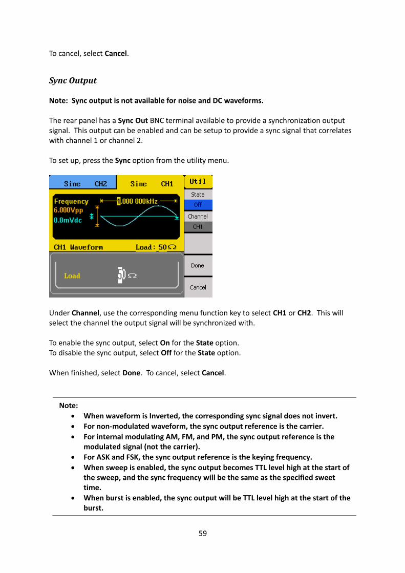
Sync Output Note: Sync output is not available for noise and DC waveforms. The rear panel has a Sync Out BNC terminal available to provide a synchronization output signal. This output can be enabled and can be setup to provide a sync signal that correlates with channel 1 or channel 2. To set up, press the Sync option from the utility menu.
Under Channel, use the corresponding menu function key to select CH1 or CH2. This will select the channel the output signal will be synchronized with. To enable the sync output, select On for the State option. To disable the sync output, select Off for the State option. When finished, select Done. To cancel, select Cancel.
Note:
When waveform is Inverted, the corresponding sync signal does not invert.
For non-modulated waveform, the sync output reference is the carrier.
For internal modulating AM, FM, and PM, the sync output reference is the modulated signal (not the carrier).
For ASK and FSK, the sync output reference is the keying frequency.
When sweep is enabled, the sync output becomes TTL level high at the start of the sweep, and the sync frequency will be the same as the specified sweet time.
When burst is enabled, the sync output will be TTL level high at the start of the burst.

60
For external gated burst, the sync output follows the external gated signal.
Frequency Counter The instrument has a built-in frequency counter. The counter input shares the same BNC terminal as the channel 2 main output terminal, labeled CNT. To access and enable the counter function, select the Counter option from the utility menu.
Note: When the counter function is enabled, channel 2 will automatically be disabled and the same BNC terminal will become the counter’s input terminal.
There are several measurement parameters that can be displayed when counter is enabled.
Measure Frequency/Period The instrument can measure in frequency or period by selecting Freq or Period respectively from the counter menu.
Measure Width and Duty The width of the signal can be measured. This parameter is especially useful for measuring square and pulse signals. Users can select between measuring positive or negative width by selecting PWidth or NWidth respectively from the counter menu. Users can also measure the duty cycle in percent of the signal by selecting Duty from the menu.

61
Adjust Reference Frequency The default reference frequency used by the counter is 10 MHz. Users can change this reference frequency by selecting RefeFreq and use the rotary knob or the numeric keypad to change the reference frequency value.
Adjust Trigger Level The trigger level of the counter can be adjusted by selecting TrigLev from the menu. Use the rotary knob or the numeric keypad to change the trigger level. The maximum trigger level value is 1.8 V, and the minimum is – 3.0 V.
Counter Settings There are some additional counter settings that can be adjusted, which may help improve the counter measurements of some signals. To access these settings, select Setup from the counter menu, and an expanded set of menu options will be available.

62
Coupling The counter can be set to AC or DC coupling. Select Mode from the menu and toggle the corresponding menu function key to change between DC or AC for DC and AC coupling respectively. HFR A high frequency reject filter can be enabled or disabled. Enabling this filter may help improve the frequency measurements of certain signals. From the menu, select HFR and toggle the corresponding menu function key to turn it On or Off. Default Settings All of the counter settings can be configured to default values by selecting Default from the menu. Below is a table of the default settings.
Counter Parameters Default Settings
Reference Frequency (RefeFreq) 10.000000 MHz
Trigger Level (TrigLev) 0.0 V
Coupling (Mode) AC
High Frequency Reject Filter (HFR) Off
Select Done to return to the counter main menu.
3.9 System Configurations The second page of the utility menu contains system parameters that can be adjusted.

63
System Settings In the utility menu, select 1/2 from the menu to go to the second page of the menu, then select the System option.
Numerical Format The number format can be changed on the instrument. Select Number Format from the menu.

64
Toggle the corresponding menu function key to select Point to choose between using period (.) or comma (,) as the decimal representation of all numerical values on display. Numeric separators can also be configured by selecting the Separator option. Choose between On, Off, or Space. Below illustrates the difference between the three on all applicable numerical values on the display.
Select Done when finished.
Language Default language is English. It can be changed to simplified Chinese by selecting the Language option from the second page of the utility menu. Press the corresponding menu function key to toggle between the two languages.
Power-On Settings The power-on instrument settings can be configured to load the default values or values
Separator: Space Separator: Off
Separator: On

65
configured during the last power-on state. This function can be used to retain instrument configurations in the case of power interruptions. Press the PowerOn option from the menu to select between Default and Last. Default will load default instrument settings during power up. Last will load instrument settings from the last power up state.
Note: The output states of both channels cannot be recalled at power-on. For safety reasons, the states are disabled by default.
Set to Factory Default You can set the instrument settings to factory default by selecting Set to Default. The instrument will change all settings to default, and the screen will return to the main display with Sine wave active. Below is a table of the factory default settings:
Parameters Default Settings
Function Sine Wave
Frequency 1.000000 kHz
Amplitude 4 Vpp
Offset 0 V
Phase 0 °
Output Impedance HighZ
Modulation
Carrier Frequency 1.000000 kHz
Modulating Frequency 100 Hz
Modulation Shape Sine Wave
AM Depth 100 %
FM Deviation 500 Hz
Key Frequency 100 Hz
FSK Hop Frequency 1 MHz
Phase Deviation 180 °
Sweep
Start/Stop Frequency 100 Hz/1.9 kHz
Sweep Time 1 second
Trig Out Off
Mode Linear
Direction ↑
Burst
Period 10.000 ms

66
Phase 0 °
Count 1 Cycle
Trig Off
Source Internal
Counter
Measurement Mode Frequency
Reference Frequency 10.000000 MHz
Trigger Level 0.0 V
Mode AC
HFR Off
Select 1/2 to go to the second page of the system menu.
Key Sound Select Beep and toggle the corresponding menu function key to turn the instrument key press sound On or Off. This will also disable the sound for any errors that may occur during front panel or remote operation.
Screen Saver The instrument has a built-in screen saver function that automatically dims the display when left idle over a period of time specified by a timer. The timer can be changed by selecting the ScrnSvr option from the menu. Press the corresponding menu function key to change between: 1 min, 5 min, 15 min, 30 min, 1 hour, 2 hours, 5 hours, Off.

67
Clock Source By default, the instrument uses an internal clock source to generate output waveforms. An external 10 MHz clock source can also be used, especially for synchronization purposes. To change to use an external clock source, select CLKSource and set it to External by pressing the menu function key. To change it to Internal, press the key again. When set to External, connect a 10 MHz reference signal to the rear BNC terminal labeled 10MHz In.
Self Test and Adjustment See section “2.3 Preliminary Check” under Output Check for details.
Check Instrument Information Press Utility and press 1/2 to go to the second page of the utility menu. Select EditInfo to see information about the instrument. You will be able to find the following: Boot up Times, Software version (firmware), Hardware version, Model, Serial Number. To exit, press any of the menu function keys or any of the waveform keys.
Updating Firmware When updates are available, users can update the firmware of the instrument by following the below steps.
1. Go to www.bkprecision.com and download the firmware update file. The file format will have a .ADS extension.
2. Save the file onto a USB flash drive, then connect the drive into the front USB connector of the instrument.
3. Once the USB drive is detected, press Utility and press 1/2 to go to the second page of the utility menu.
4. Select Update option from the menu and the instrument will go into the Store/Recall main menu.
5. Select Browser and select Folder. Then use the rotary knob or the up and down arrow keys to select USB Device (0:). Then select Browser again and change it to File.
6. On the right column, use the rotary knob or the up and down arrow keys to select the .ADS firmware file that was saved in the USB flash drive.
7. Then select Recall from the menu. Wait a few seconds and the firmware will begin updating the device.

68
8. When finished, a message will prompt you to restart the generator. At this point, power off the instrument and wait a few seconds, then power it back on.
9. The instrument will now have the updated firmware. You can verify this by checking the instrument information (follow instructions from the previous section to check).
3.10 Help System
A built-in help system is available to provide quick references on setting up common output configurations with the generator. To access the system, press the Help button from the front panel. The screen below will be displayed:
You can use the menu keys, the rotary knob, or the up and down buttons to select any of the ten items listed in the help system as shown above. Once selected (the cursor highlights the selection in blue), push the corresponding menu function key for the Select option and the screen will display a description of the selected help item. When finished, press the Cancel option from the menu to go back to the main help menu.

69
4 Troubleshooting Guide Below are some frequently asked questions and answers. Please check if any apply to your power supply before contacting B&K Precision. Q: I cannot power up the generator - Check that the power cord is securely connected to the AC input and there is live power
from your electrical AC outlet. - Verify that the AC power coming from the mains is the correct voltage. The generator
can accept a specific range of AC input voltages. Refer to section “2.1”. Q: I cannot see any output out of the output terminals - Make sure that the Output buttons above channel 1 and/or channel 2 is lit. If not,
press it once. The backlight of these Output buttons indicates that the respective channel’s output is enabled.
Q: I have connected my signal to an oscilloscope, but the amplitude is double of what I set - This is often because the impedance of the generator is not matched with the
oscilloscope. When the generator is set to 50 Ω impedance, connecting it directly to an oscilloscope with a 1 MΩ input impedance will cause this to happen. To eliminate this issue, connect a 50 Ω terminator to the input of the oscilloscope, then connect a BNC cable between the generator and the terminator to have matching impedance.
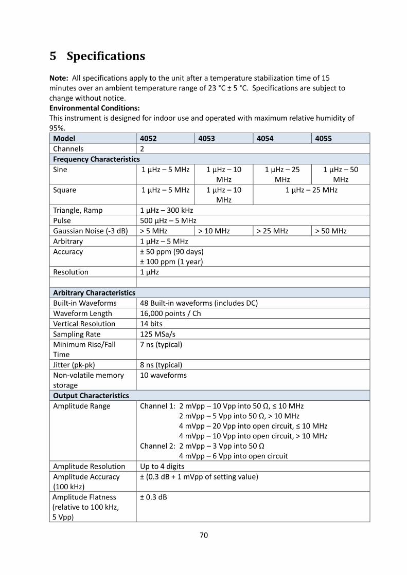
70
5 Specifications Note: All specifications apply to the unit after a temperature stabilization time of 15 minutes over an ambient temperature range of 23 °C ± 5 °C. Specifications are subject to change without notice. Environmental Conditions: This instrument is designed for indoor use and operated with maximum relative humidity of 95%.
Model 4052 4053 4054 4055
Channels 2
Frequency Characteristics
Sine 1 µHz – 5 MHz 1 µHz – 10 MHz
1 µHz – 25 MHz
1 µHz – 50 MHz
Square 1 µHz – 5 MHz 1 µHz – 10 MHz
1 µHz – 25 MHz
Triangle, Ramp 1 µHz – 300 kHz
Pulse 500 µHz – 5 MHz
Gaussian Noise (-3 dB) > 5 MHz > 10 MHz > 25 MHz > 50 MHz
Arbitrary 1 µHz – 5 MHz
Accuracy ± 50 ppm (90 days) ± 100 ppm (1 year)
Resolution 1 µHz
Arbitrary Characteristics
Built-in Waveforms 48 Built-in waveforms (includes DC)
Waveform Length 16,000 points / Ch
Vertical Resolution 14 bits
Sampling Rate 125 MSa/s
Minimum Rise/Fall Time
7 ns (typical)
Jitter (pk-pk) 8 ns (typical)
Non-volatile memory storage
10 waveforms
Output Characteristics
Amplitude Range Channel 1: 2 mVpp – 10 Vpp into 50 Ω, ≤ 10 MHz 2 mVpp – 5 Vpp into 50 Ω, > 10 MHz 4 mVpp – 20 Vpp into open circuit, ≤ 10 MHz 4 mVpp – 10 Vpp into open circuit, > 10 MHz Channel 2: 2 mVpp – 3 Vpp into 50 Ω 4 mVpp – 6 Vpp into open circuit
Amplitude Resolution Up to 4 digits
Amplitude Accuracy (100 kHz)
± (0.3 dB + 1 mVpp of setting value)
Amplitude Flatness (relative to 100 kHz, 5 Vpp)
± 0.3 dB

71
Cross Talk < -70 dBc
Offset Range (DC) Channel 1: ± 5 V into 50 Ω ± 10 V into open circuit Channel 2: ± 1.5 V into 50 Ω ± 3 V into open circuit
Offset Resolution Up to 4 digits
Offset Accuracy ± ( |Offset setting value| * 1% + 3 mV)
Output Impedance 50 Ω (typical)
Output Protection Short-circuit protection
Waveform Characteristics
Harmonic Distortion DC – 1 MHz, < - 60 dBc 1 MHz – 5 MHz, < -53 dBc 5 MHz – 25 MHz, < - 35 dBc 25 MHz – 50 MHz, < -32 dBc
Total Harmonic Distortion
DC – 20 kHz at 1 Vpp, < 0.2 %
Spurious (non-harmonic)
DC – 1 MHz, < -70 dBc 1 MHz – 10 MHz , < -70 dBc + 6 dB/spectrum phase
Phase Noise 10 kHz offset, - 108 dBc/Hz (typical)
Rise/Fall Time (Square) < 12 ns (10 % - 90 %) at full amplitude into 50 Ω
Variable Duty Cycle (Square)
20% - 80% to 10 MHz 40% - 60% to 20 MHz 50% > 20 MHz
Asymmetry (50 % duty cycle)
1% of period + 20 ns (typical,1 kHz, 1 Vp-p))
Jitter square) 0.1 % of period (typical, 1 kHz, 1 Vp-p)
Ramp Symmetry 0 % - 100 %
Linearity (Triangle, ramp at 1 kHz, 1 Vp-p, 100% symmetry)
< 0.1 % of peak output (typical)
Pulse
Pulse Width 16 ns minimum, 8 ns resolution
Rise/Fall Time 7 ns (typical) at 1 kHz, 1 Vpp from 10 % – 90%
Duty Cycle 0.1 % resolution
Overshoot < 5 %
Jitter (pk-pk) 8 ns
Burst
Waveform Sine, Square, Ramp, Pulse, Arbitrary (except DC)
Type Cycle (1 – 50,000 cycles), Infinite, Gated
Start/Stop Phase 0 ° – 360 °
Internal Period 1 µs – 500 s
Gated Source External Trigger
Trigger Source Internal, External, Manual
Phase Offset
Range 0 ° – 360 °

72
Resolution 0.1 °
Trigger Characteristics
Trigger Input
Input Level TTL compatible
Slope Rising or Falling, selectable
Pulse Width > 100 ns
Input Impedance > 5 kΩ, DC coupling
Maximum Frequency
1 MHz
Input Latency < 300 ns Trigger Output
Voltage Level TTL compatible
Pulse Width > 400 ns
Output Impedance 50 Ω
Maximum Frequency
1 MHz
Modulation Characteristics
Amplitude Modulation
Carrier Sine, Square, Ramp, Arbitrary (except DC)
Source Internal, External
Modulation Waveform
Sine, Square, Ramp, Noise, Arbitrary (2 mHz – 20 kHz)
Modulation Depth 0 % - 120 %
Frequency Modulation
Carrier Sine, Square, Ramp, Arbitrary (except DC)
Source Internal, External
Modulation Waveform
Sine, Square, Ramp, Noise, Arbitrary (2 mHz – 20 kHz)
Frequency Deviation
0 – 0.5*bandwidth, 10 µHz resolution
FSK
Carrier Sine, Square, Ramp, Arbitrary (except DC)
Source Internal, External
Modulation Waveform
50 % duty cycle square waveform (2 mHz – 50 kHz)
ASK
Carrier Sine, Square, Ramp, Arbitrary (except DC)
Source Internal, External
Modulation Waveform
50 % duty cycle square waveform (2 mHz – 50 kHz)
DSB-AM
Carrier Sine, Square, Ramp, Arbitrary (except DC)
Source Internal, External
Modulation Waveform 2 mHz – 1 kHz
Phase Modulation
Carrier Sine, Square, Ramp, Arbitrary (except DC)

73
Source Internal, External
Modulation Waveform Sine, Square, Ramp, Noise, Arbitrary (2 mHz – 20 kHz)
Phase Deviation 0 – 360 °, 0.1 ° resolution
PWM Modulation
Frequency 500 µHz – 20 kHz Source Internal, External
Modulation
Waveform Sine, Square, Ramp, Noise, Arbitrary (except DC)
External
Modulation - 6 V to + 6 V (max. width deviation)
Duty Cycle
Modulating
Frequency
2 mHz – 20 kHz
Sweep Characteristics
Waveforms Sine, Square, Ramp, Pulse, Arbitrary (except DC)
Sweep Shape Linear or Logarithmic, up or down
Sweep Time 1 ms – 500 s
Sweep Trigger Internal, External, Manual
Inputs and Outputs
Output Impedance 50 Ω , High impedance
Sync OUT TTL compatible > 50 ns width, not adjustable 50 Ω (typical) output impedance 2 MHz max. frequency
Modulation In ± 6 Vpp for 100% modulation > 5 kΩ input impedance Max. voltage input: ± 6 V
External Clock 10 MHz ± 100 Hz, TTL compatible for external unit synchronization
Ext Trig/Gate/FSK/Burst TTL compatible Max. voltage input: ± 6 V
Frequency Counter
Measurement Frequency, Period, Positive/Negative pulse width, Duty cycle
Measurement Range (typical)
Single channel: 100 mHz – 200 MHz Pulse width/Duty cycle: 1 Hz – 10 MHz
Frequency Resolution 6 bits
Voltage range (non-modulated signal)
DC Coupling (typical)
DC Offset Range: ± 1.5 VDC 100 mHz to 10 MHz, 450 mV to ± 2.5 V 10 MHz to 50 MHz, 2.5 V to 5 V 50 MHz to 200 MHz, 4.5 V to 5 V
AC Coupling 1 Hz – 100 MHz, 50 mVrms - 5 Vpp 100 MHz – 200 MHz, 100 mVrms – 5 Vpp
Pulse width/Duty cycle Voltage Range
50 mVrms – 5 Vpp

74
Input Impedance 1 MΩ
Coupling AC, DC
Trigger Level Range (typical)
-3 V to +1.8 V
General
Display Resolution 3.5” TFT-LCD Display, 320 x 240
Remote Control Interface
USBTMC (standard), GPIB (optional)
Storage Memory 10 Instrument settings, 10 Arbitrary waveforms
Dimensions (WxHxD) 213mm x 89 mm x 281 mm (8.4” x 3.5” x 11.1”)
Weight 2.6 kg (5.7 lbs)
Power 100 – 240 VAC ± 10%, 50 / 60 Hz ± 5% 100 – 120 VAC ± 10%, 45 – 440 Hz
Power Consumption 50 W max.
Temperature Operation: 0 °C – 40 °C Storage: -20 °C – 60 °C
Humidity < 35 °C, ≤ 90 % RH 35 °C – 40 °C, ≤ 60 % RH
Altitude Operation: Below 3,000 m Storage: Below 15,000 m

75
SERVICE INFORMATION
Warranty Service: Please go to the support and service section on our website at www.bkprecision.com to obtain a RMA
#. Return the product in the original packaging with proof of purchase to the address below. Clearly state on the RMA the
performance problem and return any leads, probes, connectors and accessories that you are using with the device. Non-Warranty Service: Please go to the support and service section on our website at www.bkprecision.com to obtain a
RMA #. Return the product in the original packaging to the address below. Clearly state on the RMA the performance
problem and return any leads, probes, connectors and accessories that you are using with the device. Customers not on an
open account must include payment in the form of a money order or credit card. For the most current repair charges please
refer to the service and support section on our website.
Return all merchandise to B&K Precision Corp. with prepaid shipping. The flat-rate repair charge for Non-Warranty Service
does not include return shipping. Return shipping to locations in North America is included for Warranty Service. For
overnight shipments and non-North American shipping fees please contact B&K Precision Corp.
B&K Precision Corp.
22820 Savi Ranch Parkway
Yorba Linda, CA 92887
www.bkprecision.com
714-921-9095 Include with the returned instrument your complete return shipping address, contact name, phone number and description of problem.

76
LIMITED ONE-YEAR WARRANTY B&K Precision Corp. warrants to the original purchaser that its products and the component parts thereof, will be free from
defects in workmanship and materials for a period of one year from date of purchase.
B&K Precision Corp. will, without charge, repair or replace, at its option, defective product or component parts. Returned
product must be accompanied by proof of the purchase date in the form of a sales receipt.
To help us better serve you, please complete the warranty registration for your new instrument via our website www.bkprecision.com
Exclusions: This warranty does not apply in the event of misuse or abuse of the product or as a result of unauthorized
alterations or repairs. The warranty is void if the serial number is altered, defaced or removed.
B&K Precision Corp. shall not be liable for any consequential damages, including without limitation damages resulting from
loss of use. Some states do not allow limitations of incidental or consequential damages. So the above limitation or
exclusion may not apply to you.
This warranty gives you specific rights and you may have other rights, which vary from state-to-state.
B&K Precision Corp.
22820 Savi Ranch Parkway
Yorba Linda, CA 92887
www.bkprecision.com
714-921-9095

22820 Savi Ranch Parkway
Yorba Linda, CA 92887 www.bkprecision.com
© 2013 B&K Precision Corp. v042018