40gbase-kr4 backplane phy proposal · 03/18/2008 ieee 802.3ba task force meeting, orlando, fl 1...
TRANSCRIPT

03/18/2008 IEEE 802.3ba Task Force meeting, Orlando, FL 1
40GBASE-KR4 backplane PHY proposal
Richard Mellitz & Ilango Ganga Intel Corporation
Mar 18, 2008

03/18/2008 IEEE 802.3ba Task Force meeting, Orlando, FL 2
Contributors & Supporters
Andre Szczepanek Texas InstrumentsArthur Marris Cadence Design SystemsPravin Patel IBMChris DiMinico MC CommunicationsScott Kipp BrocadeTom Palkert LuxteraJeff Cain Cisco Systems

03/18/2008 IEEE 802.3ba Task Force meeting, Orlando, FL 3
Key messages
Proposal to adopt 10GBASE-KR as a baseline for specifying 40GBASE-KR4 with the following changes
Backplane layer diagram (Clause 69)Leverage 10GBASE-KR PMD for operation over 4 lanes (Clause 72)Auto-Negotiation (Clause 73)Forward Error correction (Clause 74)

03/18/2008 IEEE 802.3ba Task Force meeting, Orlando, FL 4
Considerations for 40G BPE PHYTo be architecturally consistent with the Backplane Ethernet layer stack illustrated in Clause 69To interface to a 4-lane backplane medium with interconnect characteristics recommended in IEEE Std 802.3ap (Annex 69B)
Most generation 2 blade systems are built with 4-lanes (10Gbaud KR ready)Leverage 10GBASE-KR technology/specifications (Clause 72 and Annex 69A) to define 40GBASE-KR4 PHY:
64B/66B block codingStartup protocol (per lane)Signaling speed 10.3125Gbd (per lane)Electrical characteristicsTest methodology and procedures
Optional FEC sublayerPCS to interface to optional FEC sublayer consistent with Clause 74 specification
Compatible with Backplane Ethernet Auto-Neg (Clause 73)Enhancement to indicate 40GbE ability

03/18/2008 IEEE 802.3ba Task Force meeting, Orlando, FL 5
Backplane Ethernet overview
IEEE Std 802.3ap-2007 Backplane Ethernet defines 3 PHY types1000BASE-KX : 1-lane 1 Gb/s PHY (Clause 70)10GBASE-KX4: 4-lane 10Gb/s PHY (Clause 71)10GBASE-KR : 1-lane 10Gb/s PHY (Clause 72)
Forward Error Correction (FEC) for 10GBASE-R (Clause 74) − optionalOptional FEC to increase link budget and BER performance
Auto-negotiation (Clause 73)Auto-Neg between 3 PHY types (AN is mandatory to implement)Parallel detection for legacy PHY support
Automatic speed detection of legacy 1G/10G backplane SERDES devicesNegotiate FEC capability
Clause 45 MDIO interface for managementChannel
Controlled impedance (100 Ohm) traces on a PCB with 2 connectors and total length up to at least 1m.Channel model is informative (Annex 69B)
Interference tolerance testing (Annex 69A)Support a BER of 10-12 or better

03/18/2008 IEEE 802.3ba Task Force meeting, Orlando, FL 6
Existing backplane architecture

03/18/2008 IEEE 802.3ba Task Force meeting, Orlando, FL 7
Proposed backplane architecture with 40GbE
LLC (LOGICAL LINK CONTROL) OR OTHER MAC CLIENT
MAC CONTROL (OPTIONAL)
MAC – MEDIA ACCESS CONTROL
RECONCILLIATION
HIGHER LAYERS
64B/66BPCSFECPMAPMDAN
MEDIUM
MDI
MEDIUM
MDI
MEDIUM
MDI
10GBASE-KR
8B/10B PCSPMAPMD
8B/10B PCSPMAPMD
10GBASE-KX41000BASE-KX
GMII XGMII XGMII
PHYSICAL
DATA LINK
NETWORK
TRANSPORT
SESSION
PRESENTATION
APPLICATION
AN PMD
64B/66B PCSFECPMAPMDAN
MEDIUM
MDI
40GBASE-KR4
XLGMII
Figure 69-1 Architectural positioning of Backplane Ethernet

03/18/2008 IEEE 802.3ba Task Force meeting, Orlando, FL 8
Proposed Auto-Neg changesIEEE Std 802.3ap defines Auto-Negotiation for backplane Ethernet PHYs
AN uses DME signaling with 48-bit base pages to exchange link partner abilitiesAN is mandatory for 10GBASE-KR backplane PHY, negotiates FEC ability
Proposal for 40GBASE-KR4 (Ability to negotiate with other 802.3ap PHYs)Add a Technology Ability bit A3 to indicate 40GbE ability (A3 is currently reserved)No changes to backplane AN protocol or management register formatNo change to negotiate FEC ability, FEC when selected to be enabled on all 4 lanesAN mandatory for 40GBASE-KR4, no parallel detect required for 40G
A3 40GBASE-KR4A4 through A24 Reserved for future technology

03/18/2008 IEEE 802.3ba Task Force meeting, Orlando, FL 9
Proposed 40GBASE-KR4 PMD
Leverage 10GBASE-KR (Clause 72) to specify 40GBASE-KR4 with following changes for 4 lane operation
Change KR Link diagram for 4 lanes (similar to KX4)Change KR PMD service interface to support 4 logical streams (similar to KX4)Change PMD control variable mapping table to include management variables for 4 lanes

03/18/2008 IEEE 802.3ba Task Force meeting, Orlando, FL 10
40GBASE-KR4 Link block diagram
03/18/2008 IEEE 802.3ba Task Force meeting, Orlando, FL 11
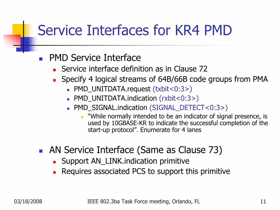
Service Interfaces for KR4 PMD
PMD Service InterfaceService interface definition as in Clause 72Specify 4 logical streams of 64B/66B code groups from PMA
PMD_UNITDATA.request (txbit<0:3>)PMD_UNITDATA.indication (rxbit<0:3>)PMD_SIGNAL.indication (SIGNAL_DETECT<0:3>)
“While normally intended to be an indicator of signal presence, is used by 10GBASE-KR to indicate the successful completion of the start-up protocol”. Enumerate for 4 lanes
AN Service Interface (Same as Clause 73)Support AN_LINK.indication primitiveRequires associated PCS to support this primitive

03/18/2008 IEEE 802.3ba Task Force meeting, Orlando, FL 12
PMD MDIO function mapping (1)
Support management variables for 4 lanesInclude lane by lane Transmit disable

03/18/2008 IEEE 802.3ba Task Force meeting, Orlando, FL 13
PMD MDIO function mapping (2)Support management variables for 4 lanes
Add lane by lane signal detectEnumerate status indication per lane as appropriate

03/18/2008 IEEE 802.3ba Task Force meeting, Orlando, FL 14
KR4 PMD transmit & receive functions
PMD transmit function (enumerate for 4 lanes)Converts 4 logical streams from PMD service interface into 4 separate electrical streams delivered to MDISeparate lane by lane TX disable function in addition to Global TX disable function
PMD receive function (enumerate for 4 lanes)Converts 4 separate electrical streams from MDI into 4 logical streams to PMD service interfaceSeparate lane by lane signal detect function in addition to Global TX disable function
Same electrical specifications as defined in Clause 72 for 10GBASE-KR PMD
Receiver Compliance defined in Annex 69A (Interference Tolerance Test) and referenced in Clause 72

03/18/2008 IEEE 802.3ba Task Force meeting, Orlando, FL 15
PMD Control functionStartup & Training
Reuse Clause 72 control function for KR4 PMD (Startup & Training)
Used for tuning equalizer settings for optimum backplane performanceUse Clause 72 training frame structureUse same PRBS 11 pattern, with randomness between lanes
Same Control channel spec as in Clause 72, enumerated per lane
All 4 lanes are independently trainedReport Global Training complete only when all 4 lanes are trainedSame Frame lock state diagram (Fig 72-4)Same Training state diagram with enumeration of variables corresponding to 4 lanes (Fig 72-5)

03/18/2008 IEEE 802.3ba Task Force meeting, Orlando, FL 16
Electrical characteristics
40GBASE-KR4 Transmit electrical characteristics
Same as 10GBASE-KR TX characteristics and waveforms as specified in Clause 72Same test fixture setup as in Clause 72
40GBASE-KR4 Receiver electrical characteristics
Same as 10GBASE-KR RX characteristics specified in Clause 72 and Annex 69 A

03/18/2008 IEEE 802.3ba Task Force meeting, Orlando, FL 17
Receiver Interference tolerance test
Test procedure specified in Annex 69AReceiver interference tolerance parameters for 40GBASE-KR4 PMD
Same as Receiver interference tolerance test parameters as in Clause 72No change to broadband noise amplitude for KR4

03/18/2008 IEEE 802.3ba Task Force meeting, Orlando, FL 18
Forward Error Correction
Reuse FEC specification for 10GBASE-R (Clause 74)
The FEC sublayer transparently passes 64B/66B code blocksChange to accommodate FEC sync for 4 lanes
Same state diagram for FEC block lockReport Global Sync achieved only if all lanes are lockedPossibly add a FEC frame marker signal that could be used for lane alignment

03/18/2008 IEEE 802.3ba Task Force meeting, Orlando, FL 19
Interconnect Characteristics
Interconnect characteristics (informative) for backplane is defined in Annex 69B
No proposed changes
40GBASE-KR4 PHY to interface to the 4 lane backplane medium to take advantage of 802.3ap KR ready blade systems in deployment
03/18/2008 IEEE 802.3ba Task Force meeting, Orlando, FL 20
Summary
Summary40GbE backplane PHY to be architecturally consistent with IEEE Std 802.3ap layer stackAdopt 10GBASE-KR as baseline to Specify 40GBASE-KR4 PHY with appropriate changes proposed in this documentInterface to 4 lane backplane medium to take advantage of 802.3ap KR ready blade systems in deployment
Appropriate changes to add EEE feature, when adopted by 802.3az for KRPCS proposals and interface definitions to accommodate backplane Ethernet architecture (including FEC and AN)

03/18/2008 IEEE 802.3ba Task Force meeting, Orlando, FL 21
Backup

03/18/2008 IEEE 802.3ba Task Force meeting, Orlando, FL 22
Typical backplane system illustration
L2
L4
L1
L3
10GbE Switch card (Redundant)10GbE Switch card
Compute Blades or Line cards
Backplane
L1L2L3L4
10GbE personality card or mezzanine
(Some configurations may not include a mezzanine)
4-lanes4-lanes
Note: The switch cards are shown at the chassis edge for simplicity.In real systems there could be multiple fabrics located at the center, edge, or rear of the chassis
Backplane Connectors

03/18/2008 IEEE 802.3ba Task Force meeting, Orlando, FL 23
Proposed 40GbE interfaces
MEDIUM
MDI
4 Lane Distributor
FEC
PMA
PMD
“40GBASE-?R4” or 100GBASE-???
FEC Service Interface (Abstract or XLAUI)
PMA Service Interface (electrical, XLAUI)
PMD Service Interface (abstract or logical)
PCS 64B/66B
XLGMII(logical)
XLAUI
MAC-PHY interface
RS, MAC AND HIGHER LAYERS
4 lanes
Inter-sublayer interfaces common to 40/100G where possible
XLGMII (intra-chip)Logical; define data, clock, no electricals
PCS64B/66B encodingFixed 4-lane distributor based on 64B/66B header for alignmentUsed for backplane & XLAUI
XLAUI (chip to chip)Define electricals
FEC service interface Abstract, can optionally use XLAUI
PMA Service interfaceDefine electricals, same as XLAUI
PMD Service interfaceAbstract, or logical
Optional overhead can be used with Optical PHYs
Auto-Neg for Backplane located below PMD

03/18/2008 IEEE 802.3ba Task Force meeting, Orlando, FL 24
Possible implementation examples
MAC PCS64B/66B
PMAx4
PMDSerial4xKR
4L
4L
XLAUI
40GbE separate Backplane PHY
4L
4LBackplane
MAC PCS64B/66B
64
64
XLGMII
40GbE integrated backplane PHY
PMAx4
PMDSerial4xKR
4L
4LBackplaneFEC
x4
FECx4
MAC-PHY interface (Chip to Chip)
MAC-PHY interface (intra-chip)
AN
AN