415480e esf(11版 英文)
TRANSCRIPT

65ZX415480E-11 1/21
Eddysonic Flowmeter
ESF
Operation Manual
Surpass Industry Co., Ltd.
2020/4

65ZX415480E-11 2/21
Read Before Use Before using this product, check the
compatibility of the type of liquid to use and the wetted parts material in this product.
All users are required to carefully read and understand this manual before operation of the product.
Keep this manual in good condition and close at hand for quick reference whenever necessary.
Use the product only as intended, and only as directed in this manual.
Cautionary notes in this manual must be fully understood and complied with at all times.
About This Operation Manual The contents of this manual are subject to
change without prior notice, due to improvements in product functionalities and / or performance.
No part of this manual may be reproduced in any form or by any means.
Although this manual has been prepared with all possible care, please do not hesitate to contact Surpass Industry about errors, omissions, or any other points of doubt.
Important Safety Instructions <Symbols in This Operation Manual> Warnings and cautionary notes are provided in this manual to ensure this product is used correctly and to prevent personal injury and property damage. The meanings of the WARNING and CAUTION symbols in this manual are as described below. Read and understand these notes before reading the rest of this manual.
Specific Warnings
When mounting connector parts, comply with the instructions issued by each connector manufacturer. Loose connections may result in disconnection or chemical leakage. The use of dangerous chemicals, solvents, and gases may cause physical impairment.
Do not use the product in areas where corrosive gases are being ejected. Corrosion in the body and connector may result in liquid leakage. The use of dangerous chemicals, solvents, and gases may cause physical impairment.
Obey these instructions. - Refrain from excessive tightening of the connector parts. - Do not install the product in areas of excessive vibration
or shock. - Use the product only within the specified operating
environment. Otherwise, damage to the body and connector may occur and result in liquid leakage. The use of dangerous chemicals, solvents, and gases may cause physical impairment.
This product is designed for indoor-only use. Do not apply this product to outdoor use.
WARNING This product is not explosion-proof. Never use it with
flammable fluids such as solvents. Doing so may cause fire and or explosion and is highly dangerous.
Never use with gas-permeable liquids (hydrofluoric acid, hydrochloric acid, nitric acid, ozone, etc.). Gas permeation may lead to product failure.
Never disassemble or alter the product. Doing so will cause breakage of the product and possible liquid leakage. The use of dangerous chemicals, solvents, and gases may cause physical impairment.
Do not insert screwdrivers, wires, or other objects into the tube parts. Doing so will cause product failure and possible liquid leakage. The use of dangerous chemicals, solvents, and gases may cause physical impairment.
Refrain from excessive pulling or bending of the cables. Doing so may cause wiring disconnections, which may cause electrical shock and fire hazards.
WARNING
This symbol indicates warnings against impending danger which, if not observed, may cause death or severe injury to the user.
DANGER
This symbol indicates warnings which, if not observed, may physically impair the user or damage surrounding objects. CAUTION
This symbol indicates warnings which, if not observed, may cause death or severe injury to the user. WARNING
Provides important notices and instructions for correct operation of the product.

65ZX415480E-11 3/21
Product Description Eddysonic Flowmeter, that has the part in contact with liquid made of PFA and provides connection with no use of seal-tapes resulting in potentially leakage, is the ideal flowmeter used to measure the flow rates of chemical liquids. <Operating Principle> If a liquid flows past a shedder body, a regular pattern pf vortices called Karman Vortex Street alternately trails aft in the wake. Provided that the vortex shedding frequency is f, the width of shedder body is d, and the flow velocity is v, the relationship of them can be expressed by the following formula.
f = St・v/d Where St, the Strouhal Number is a dimensionless constant which defines the quality of the vortex measurement. The Strouhal Number is constant over wide Reynolds Number ranges when the shedder body is designed with optimal dimensions. Therefore, we can obtain the value of v, by measuring the vortex shedding frequency f and then derive the volume flow value from the measured v. This flowmeter, as shown below, is equipped with an ultrasonic sensor that consists of a pair of transmitter (TX) and receiver (RX). This sensor is mounted aft the wake of the shedder body. Ultrasonic waves that constantly are sent out from TX pass through the liquid for a certain time to reach the receiver. As shown in below, if a Karman vortex street trails in the contrary direction to the ultrasonic wave oscillating direction, it takes much time for ultrasonic waves to reach RX. Conversely, if a Karman vortex street trails in the same direction as ultrasonic wave oscillating direction, it takes less time for ultrasonic waves to reach RX. Since the ultrasonic wave oscillating time varies proportional to the vortex shedding frequency, we can obtain the measured flow by detecting any changes in ultrasonic wave oscillating time. This ultrasonic sensor, mounted outside the tubes connected to flowmeter, allows non-touching measurement in which we can measure the flow rates without directly touching. Also, the ultrasonic sensor provides the excellent features, resistance to vibration and high sensibility.
Operating Principle of Eddysonic Flowmeter
RX
Ultrasonic Waves
RPASS
Housing
Karman VortexShedder Body
65ZX415480E-11 4/21
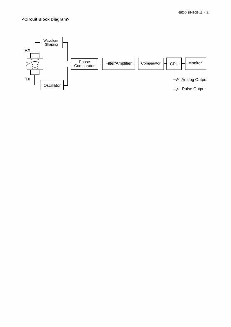
<Circuit Block Diagram>
RX
TX
Pulse Output
Analog Output
Phase Comparator
Filter/Amplifier CPU
Oscillator
Monitor
Waveform Shaping
Comparator

65ZX415480E-11 5/21
Specifications
Model ESF-10 ESF-10V ESF-15 ESF-15V Applicable Fluid Fluids not corrosive or permeable against fluorocarbon resin
Flow Meter Range (at water) (※1)
0.5 ~ 3.5 L/min (at 1x10⁻⁶ m2/s)
1 ~ 16 L/min (at 1x10⁻⁶ m2/s)
Indicating Flow Rate 0.0 ~ 4.0 L/min 0.0 ~ 18.0 L/min
Measurement Accuracy (※2)
Monitor ±5%F.S. (DI Water at 25C) ±2.5%F.S. (DI Water at 25C)
Analog output
±6%F.S. (DI Water at 25C) ±3.5%F.S. (DI Water at 25C)
Environment Humidity 5 ~ 80 %RH(Non-condensing) Environment Temperature 5 ~ 60C (41 ~ 140F)
Fluid Temperature 5 ~ 85C (41 ~ 185F) Fluid Pressure (※3) Max. 800 kPa (at 25C)
Connecting Tube Diameter φ3/8”xφ1/4”
(φ9.53xφ6.35) φ1/2”xφ3/8”
(φ12.7xφ9.5) Wetted Parts PFA
Mounting Position Horizontal, vertical, or diagonal
Analog Output
Output DC 4 ~ 20 mA Response time Appox. 2 seconds
Load Resistance 500Ω or less 250Ω or less 500Ω or less 250Ω or less
Pulse Output
Output NPN open collector Excitation
Voltage/Current Max. DC 30 V / 80 mA
Pulse Unit 10 mL/P Pulse Range 5 ms
High and Low
Boundary Output
Output NPN open collector
Excitation Voltage/Current
Max. DC 30 V / 80 mA
Power Supply DC 24 V ±10% DC 12 V ±10% DC 24 V ±10% DC 12 V ±10%Current Consumption 120 mA or less Standard cable length 2 m (78.8”)
Because the product is damaged on the condition that a fluid temperature change occurs rapidly, please don’t use it in that condition.
To prevent abnormal output, please keep an inner pressure of pipes more than 100kPa when stops water flow.

65ZX415480E-11 6/21
Model ESF-20 ESF-25
Applicable Fluid Fluids not corrosive or permeable against fluorocarbon resin Flow Meter Range
(at water) (※1) 2 ~ 40 L/min
(at 1x10⁻⁶ m2/s) 5 ~ 130 L/min
(at 1x10⁻⁶ m2/s) Indicating Flow Rate 0.0 ~ 44.0 L/min 0.0 ~ 145.0 L/min
Measurement Accuracy (※2)
Monitor ±1.5%F.S. (DI Water at 25C) ±2.5%F.S. (DI Water at 25C)
Analog output
±2.5%F.S. (DI Water at 25C) ±3.5%F.S. (DI Water at 25C)
Environment Humidity 5 ~ 80 %RH(Non-condensing) Environment Temperature 5 ~ 60C (41 ~ 140F)
Fluid Temperature 5 ~ 85C (41 ~ 185F) Fluid Pressure (※3) Max. 600 kPa (at 25C) Max. 450 kPa (at 25C)
Connecting Tube Diameter φ3/4”xφ5/8”
φ19.05xφ15.8 or φ19xφ16
φ1”xφ7/8” (φ25.4xφ22.2)
Wetted Parts PFA Mounting Position Horizontal, vertical, or diagonal
Analog Output
Output DC 4 ~ 20 mA Response time Appox. 2 seconds
Load Resistance 500Ω or less
Pulse Output
Output NPN open collector Excitation
Voltage/Current Max. DC 30 V / 80 mA
Pulse Unit 10 mL/P 100 mL/P Pulse Range 5 ms
High and Low
Boundary Output
Output NPN open collector
Excitation Voltage/Current
Max. DC 30 V / 80 mA
Power Supply DC 24 V ±10% Current Consumption 120 mA or less Standard cable length 2 m (78.8”)
Because the product is damaged on the condition that a fluid temperature change occurs rapidly, please don’t use it in that condition.
To prevent abnormal output, please keep an inner pressure of pipes more than 100kPa when stops water flow.

65ZX415480E-11 7/21
※1 Instructions on range of flow rate
Kinetic viscosity of liquids [x 10-6 m2/s]
1 2 3 4 5 6 7 Maximum flow
rate [L/min] ESF-10 Minimum flow rate
of liquids [L/min] 0.5 1.0 1.5 2.0 2.5 3.0 - 3.5
ESF-15 Minimum flow rate of liquids [L/min]
1 2 3 4 5 6 7 16
ESF-20 Minimum flow rate of liquids [L/min]
2 4 6 8 10 12 14 40
ESF-25 Minimum flow rate of liquids [L/min]
5 10 15 20 25 30 35 130
◎The minimum flow rates of the liquids, of which kinetic viscosity are more than 2 [x10-6m2/s],
are the theoretical values and may be different from the actual values. ※2 Instructions on measurement accuracy Because the measuring part of this flowmeter is made of resin, the temperature change of the target liquid affects the inner diameter of the measurement tube, causing some deviation in measurement characteristics. If the liquid temperature is higher than 50℃ and the accuracy specified by the specifications is required, correct the displayed output of the flowmeter using the following formula: Actual flow volume under your operating conditions = Displayed output of flowmwter x {1+(0.0006x(T-25))}
T : Liquid temperature under your operating conditions (C)
※3 Instructions on operating liquid pressure The maximum operating pressure depends on the liquid temperature. To derive the maximum operating pressure for the specific liquid temperature, use the following formula: ・ESF-10,ESF-15 Maximum acceptable operating pressure = 800x{1-((T-25)x0.0043)} (kPa) T : Liquid temperature (C) at your usage ・ESF-20 Maximum acceptable operating pressure = 600x{1-((T-25)x0.0043)} (kPa) T : Liquid temperature (C) at your usage ・ESF-25 Maximum acceptable operating pressure = 450x{1-((T-25)x0.0043)} (kPa) T : Liquid temperature (C) at your usage
65ZX415480E-11 8/21
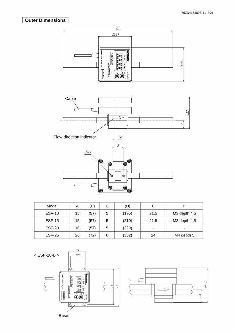
Outer Dimensions
Flow direction indicator
Cable
Model A (B) C (D) E F
ESF-10 15 (57) 5 (195) 21.5 M3 depth 4.5
ESF-15 15 (57) 5 (210) 21.5 M3 depth 4.5
ESF-20 16 (57) 5 (229) - -
ESF-25 26 (72) 0 (352) 24 M4 depth 5
Base
< ESF-20-B >

65ZX415480E-11 9/21
Names of Display Panel
Monitor
High Output Alarm Indicator Lamp
High alarm selector mode/ UP key
Low Output Alarm Indicator Lamp
Low alarm selector mode / DOWN key

65ZX415480E-11 10/21
Mounting and Connecting the Connector Parts If you wish to anchor your Flowmeter, use the threaded holes of the bottom position or the mounting holes in the base. When connecting the connector parts, tighten the connector while preventing the body from turning. In order to install connector parts correctly, always refer to the relevant catalog or operation manual issued by the connector manufacturer. ●The tube can be mounted in horizontal, vertical and diagonal. However, in any case, the tubing system
must be filled with the liquid at all times. ●Design straight-tube parts on both sides of flowmeter. The straight-tube length of IN side must be at least
7 times longer than the bore diameter, and that of OUT side must be at least 5 times longer than the bore diameter.
Before tubing, confirm the correct flow direction by checking the arrow direction of “IN→OUT”marked on the side of flowmeter unit.
Incorrect tubing system may result in personal injury due to liquid leakage caused by damage of flowmeter unit.
Before mounting, align the axes of tubes on both sides to avoid excessive stress to the flowmeter. Incorrect axial alignment may result in personal injury due to liquid leakage caused by damage of flowmeter unit.
When tubing, use tubes of the specified size. Using other tubes may result in personal injury due to fluid leakage.
When mounting connector parts, comply with the instructions issued by each connector manufacturer. Loose connections may result in disconnection or chemical leakage. The use of dangerous chemicals, solvents, and gases may cause physical impairment.
Refrain from excessive tightening of the connector parts. Otherwise, damage to the body and connector may occur and result in liquid leakage. The use of dangerous chemicals, solvents, and gases may cause physical impairment.
WARNING
The IN or OUT side’s tube of which bore diameter is smaller than that of flowmeter may generate an error in measurement.
When using flowmeter, be sure to release the airs inside its tube. An existence of air in tubing system may prevent the flowmeter from indicating a correct flow value.
If air bubbles enter into the liquid, the bubbles may remain in the Karman vortex generating part of the main unit, resulting in incorrect measurement.
CAUTION
We recommend the vertical tubing system. To prevent gas-liquid two-phase flows, design the tubing system in which the measured liquids flow to the upward direction (bottom-top).
Liquid filled
Flowing upward

65ZX415480E-11 11/21
<Pressure at Downstream Side> To prevent the occurrence of cavitations(※4), the pressure value at the downstream side should be more than one obtained from the following formula. Pd = 2.7⊿P+1.3P0 Pd : Pressure values at the downstream side [kPa] ⊿P: Pressure loss values [kPa] P0 : Vapor pressure values of liquids [kPa abs] ※4 Cavitations Phenomenon that the liquid evaporates, generating air bubbles, when the liquid pressure drops to the saturated vapor pressure or below.
<Pressure Loss>
Pre
ssur
e Lo
ss⊿
P [
kPa]
Flow Rate [L/min]
0.1 1 10 100 200
200
100
10
1
ESF-25
ESF-20
ESF-15ESF-10

65ZX415480E-11 12/21
Points to Observe When Installing To prevent erroneous operation or premature wear, do not install in: ●Gas-liquid two-phase flows or flows containing bubbles may result in malfunction. ●Mount the flowmeter in the places where no bubble flows into or gets trapped inside the flowmeter. ●Do not use this product for slurry liquids or liquid containing foreign substances. Such usage may
degrade the system performance. ●Do not mount heat exchangers or similar devices upstream, nearest to the flowmeter. Sharp
changes in liquid temperature may result in malfunction. Keep the heat exchanger or similar devices away from the flowmeter to avoid sharp temperature changes.
●Do not mount the flowmeter in the places that may provide high temperature gradients or sharp temperature changes.
●Large ripples of bellows pumps or similar devices may result in errors in measurement. Minimize the ripples by using dampers or similar devices.
●Mount the flowmeter in the places where you can easily do inspection and tubing work. ●When wiring, do not connect the cables close to large-capacity motors or transformers, noise source
such as power sources, and high-voltage/high-current sources. Neglecting this may result in malfunction due to induction.
Areas of low temperature
Areas where corrosive or explosive gases are
being ejected
Areas of excessive vibration
Areas that may be submerged in water or
where subject to splashing liquids
Areas that may be struck by lightning
Areas of high temperature
Areas of excessive noise
Outdoor

65ZX415480E-11 13/21
Wiring
Observe these precautions to connect the leads correctly. ※Black, Blue leads are connected each other within the circuit.
Never do wiring work when power supply is on. Doing so may cause electrical shock. Refrain from excessive pulling or bending of the cables. Doing so may cause disconnections
which may cause electrical shock and fire hazards. Make sure to connect all leads correctly. Failure to do so may cause the product to fail. Apply the voltage in the specified range. Overvoltage may result in smoking or fire. Do not apply the voltage and current above the capacity to the pulse output (open collector
output). Damages may occur.
CAUTION
Wiring diagram
Name of Signal Color
ESF type DC24V Power SupplyESF-V type DC12V Power supply
Red
0 V Power Supply Black 4 ~ 20 mA Output (+) White 4 ~ 20 mA Output (-) Blue
Pulse Output (+) Yellow High / Low Boundary Output (+) Gray
Yellow
Shielding
F.G
Black
Gray
Blue
White
Red
Mai
n ci
rcui
t Recorder ESF type(DC24V)
ESF-V type(DC12V)Power supply
Integrating flowmeter (Counter)
High / LowBoundary

65ZX415480E-11 14/21
<Power Supply Connecting> Connect to a DC24V power supply (ESF type) or a DC12V power supply (ESF-V type). To obtain the specified accuracy, warm up your flowmeter for at least 20 minutes. <Analog Output> Connect a load resistance between 4 ~ 20mA Output (+) and 4 ~ 20mA Output (-). The value of load resistance of 500Ω or less (ESF type) or 250Ω or less (ESF-V type). <High/Low Boundary Output> The high/low boundary output is a NPN open collector output. Connect a load resistance between high/low boundary output (+) and power supply (+). Below are examples of load resistance. e.g.) Load resistance 1kΩ 1W (Excitation Voltage 24V or less) 1kΩ 1/2W (Excitation Voltage 12V or less) 10kΩ 1/4W (Excitation Voltage 12V or less) <Pulse Output> The pulse output is a NPN open collector output. Connect a load resistance between pulse output (+) and power supply (+). Below are examples of load resistance. e.g.) Load resistance 1kΩ 1W (Excitation Voltage 24V or less) 1kΩ 1/2W (Excitation Voltage 12V or less) 10kΩ 1/4W (Excitation Voltage 12V or less) <Relationship of Flow and Analog Output>
Flow [L/min]
22
4
Cur
rent
Out
put
20
[mA]
0
(1) Overflow
The analog output increases proportional to flow in the range of (1) L/min.
<Flow Range> ESF-10 0.5 ~ 3.5 L/min ESF-15 1 ~ 16 L/min ESF-20 2 ~ 40 L/min ESF-25 5 ~ 130 L/min
At overflow (“OFLO” indicated), the analog output levels off at the maximum flow rate current.
<Overflow Range> ESF-10 4 L/min or more ESF-15 18 L/min or more ESF-20 44 L/min or more ESF-25 145 L/min or more

65ZX415480E-11 15/21
Setting the High/Low Boundary Value
<ESF-10・ESF-15・ESF-20>
◇Setting high boundary value (1) Press and hold the SET HI (▲) button for at
least one seconds. -The high output alarm indicator lamp will light
up, and an “H” will appear in the display. (2) Adjust the high boundary value setting by
pressing the ▲ ▼ button. -The value on the display increases or
decreases by 0.1. -The numbers can be fast forward or reversed
by holding down on the ▲ or ▼ button. (3) After releasing the ▲ or ▼ button, the display
will return to flow measuring mode in five seconds.
◇Setting low boundary value (1) Press and hold the SET LO (▼) button for at
least one seconds. -The low output alarm indicator lamp will light
up, and an “L” will appear in the display. (2) Adjust the low boundary value setting by
pressing the ▲ ▼ button. -The value on the display increases or
decreases by 0.1. -The numbers can be fast forward or reversed
by holding down on the ▲ or ▼ button. (3) After releasing the ▲ or ▼ button, the display
will return to flow measuring mode in five seconds.
The setting range depends on the flowmeter model.
<Setting range for each model>
When setting the low boundary value, be sure to set the value less than the high boundary value. The low boundary value exceeding the high boundary value may cause malfunction of the product.
CAUTION
ESF-10 0.0 ~ 3.5 ESF-15 0.0 ~ 16.0 ESF-20 0.0 ~ 40.0

65ZX415480E-11 16/21
<ESF-25> ◇Setting high boundary value (1) Press and hold the SET HI (▲) button for at
least one seconds. -The high output alarm indicator lamp will light
up. (2) Adjust the high boundary value setting by
pressing the ▲ ▼ button. -The value on the display increases or
decreases by 0.1. -The numbers can be fast forward or reversed
by holding down on the ▲ or ▼ button. (3) After releasing the ▲ or ▼ button, the display
will return to flow measuring mode in five seconds.
◇Setting low boundary value (1) Press and hold the SET LO (▼) button for at
least one seconds. -The low output alarm indicator lamp will light
up. (2) Adjust the low boundary value setting by
pressing the ▲ ▼ button. -The value on the display increases or
decreases by 0.1. -The numbers can be fast forward or reversed
by holding down on the ▲ or ▼ button. (3) After releasing the ▲ or ▼ button, the display
will return to flow measuring mode in five seconds.
<Setting range>
ESF-25 0.0 ~ 130.0
When setting the low boundary value, be sure to set the value less than the high boundary value. The low boundary value exceeding the high boundary value may cause malfunction of the product.
CAUTION

65ZX415480E-11 17/21
Flow Diagram of High/Low Boundary Setting
<Setting low boundary value> <Setting high boundary value>
Low boundary setting mode LO indication lights up
( )decreases the value by 0.1
( )increases the value by 0.1
Set the low boundary value
Flow volume measuring mode
NO
YES
NO
YES
NO
Press ( ) at least for 1 second
The low boundary value is stored
Flow volume measuring mode
( ) and ( ) are not pressed for 5 seconds or longer
High boundary setting mode HI indication lights up
( )decreases the value by 0.1
( )increases the value by 0.1
Set the high boundary value
YES
NO
YES
Press ( ) at least for 1 second
The high boundary value is stored
( ) and ( ) are not pressed for 5 seconds or longer

65ZX415480E-11 18/21
High/Low Boundary Output and LED light-up state
<High/Low boundary output> <LED light-up state>
Flow Range
② ① ③ Lower than Low
boundary value
Between High and
Low boundary values
Higher than High boundary value
LED
Light-up State
Description of LED
indication
LO indication turns
off. (Only the HI
indication lights up.)
Both of HI and LO indications light up.
HI indication turns
off. (Only the LO indication lights up.)
② ① ③
[L/min] 0
High Boundary Setting Value
Low Boundary Setting Value
ON
OFF
Hig
h/Lo
w
Bou
ndar
y O
utpu
ts
SURPASS ESF-10
HI LO SETHI LO
EDDYSONI
SURPASS INDUTRY CO.、LTD.
LO turns off
HI LO
EDDYSONI
SURPASS INDUTRY CO.、LTD.
HI & LO Light-Up
SURPASS ESF-10
SETHI LO
HI LO
EDDYSONI
SURPASS INDUTRY CO.、LTD.
HI turns off
SURPASS ESF-10
SET HI LO

65ZX415480E-11 19/21
Maintenance and Inspection This product should be inspected regularly, about twice a year depending on the usage. During the regular inspection, check the
- appearance - corrosion, clogging, leakage, etc., from the connector parts.
<Safety Notes on Maintenance and Inspection>
Storage For potentially long term storage, store the product in the places where the following environmental conditions are satisfied. ・Being kept dry. ・Appropriate vibration or shock. ・Temperature of 5C to 60C and humidity of 5% to 80% RH (non-condensing). ・Places free from coarse particles. ・Places not exposed to direct sunshine.
If using dangerous chemicals, solvents, gases, etc., make sure to wear protective, chemical resistant gear (protective gloves, mask, and clothing) to protect your entire body. Ejected liquids may result in physical impairment.
Before disconnecting this product from the piping system, make sure the line is depressurized. Otherwise, the fluid inside will eject and may result in physical impairment.
When replacing parts, or when performing maintenance or inspection, turn off the switch, and release the fluid inside the piping to depressurize the line. Otherwise, the fluid inside will eject and may result in physical impairment.
DANGER unless these precautions are not obeyed!

65ZX415480E-11 20/21
In Case of Breakdown
Symptom Cause Countermeasure No output value displayed with a flow.
Incorrect wiring. Check the wiring diagram and correct the wiring.
Incompatible power, voltage. Check the power supply and voltage. The tubing system is not filled with the liquid.
Fill the liquid inside the tubing system.
The flow rate is outside the measurable range.
Check the measurable range and choose the product.
Output value displayed without a flow.
The tubing system is not filled with the liquid.
Fill the liquid inside the tubing system.
The liquid in tubes is fluctuating due to large ripple.
Minimize the ripples by using dampers or similar devices.
Large errors in measurement detected.
Incompatible power, voltage. Check the power supply and voltage. Incompatible load resistance. Use the load resistance of
ESF type・・・・・・500Ω or less. ESF-V type・・・・250Ω or less.
There is noise-generating equipment nearby.
Move the noise-generating equipment from the vicinity.
There is flow-blocking equipment nearest to IN side of flowmeter.
Change the mounting position of flowmeter. (keep the rated straight-tube length as follows) IN side : 7 times longer than the bore
diameter OUT side : 5 times longer than the bore
diameter Cavitations are generated. Keep the rated line pressure to prevent
cavitations. There are bubbles contained in the liquid.
Do tubing not to have mixed bubbles.
There are foreign substances caught by shedder body.
Remove the foreign substances.
Notify your nearest sales office for problems not listed above.

65ZX415480E-11 21/21
Notes on Warranty The warranty runs for one year after the day when Surpass Industry products are delivered from Surpass factory in Japan. In case Surpass Industry should agree in writing that the defects in performance or material were caused by faulty design or workmanship of Surpass Industry, replacement products will be supplied free of charge. This warranty shall not be applied to any defects caused by misuse, alteration, neglectful treatment, and neglect of our recommendations or instructions. In addition, we are not be liable to any direct or consequential loss, damage, and personal injury due to an unauthorized usage in combination with other products and an improper usage outside of the specifications. Our product warranty shall be limited to replacement of product. Replacement with expense to the purchaser shall be applied to the followings: Any defective products caused by usage that is not described in the Instruction Manual. Any defective products caused by neglectful treatment. Any defective products caused by decomposition, alteration, and improper adjustment or repair. Any defects of products caused by acts of God including natural disaster or fires. Consumables and accessories.
Surpass Industry Co., Ltd. 2203 Shimooshi, Gyoda-shi, Saitama 361-0037 Japan TEL: +81 48 554 9760 FAX: +81 48 554 9906 URL: http://www.surpassindustry.co.jp C 2005-2020 Surpass Industry Co.,Ltd. All rights reserved.